Hexagon Mining HUBSMUGA Device that enables communication and location between the mining assets and the UG Dispatch System User Manual Hexagon MIning Technical Publications
Leica Geosystems Device that enables communication and location between the mining assets and the UG Dispatch System Hexagon MIning Technical Publications
User Manual
HUB SM|UG
Technical Reference Manual
Hardware Version: v1.0
Version No.2.0 Issued January
2017 English
MINING OPERATIONS

Devex Mining is committed to providing only the highest standards in technical
documentation and training.
Through a continual process of review and renewal, based on industry standards, client
feedback and best practice, we ensure our products are supported by quality documentation
and training.
From product offerings to customer support, Devex Mining is governed by the overarching
principal that the customer comes first. We offer comprehensive documentation and training;
ensuring client needs are met and exceeded.
Devex Mining is a division of Hexagon Mining
Devex Mining delivers leading solutions for fleet management and production optimization,
machine maintenance, business intelligence and analytics.
Devex Mining is part of Hexagon Mining, the only global provider of surface and underground
smart mining solutions that integrate design, planning, and operations technologies for safer,
more productive mines. Learn more at hexagonmining.com.
Devex HUB SM|UG Technical Reference v2.0
This document and any information or descriptive matter contained therein is communicated
in confidence and is the copyright property of Devex Mining Neither the whole, nor any
extract may be disclosed, loaned, copied, or used in manufacturing or tendering purposes
without their written consent.
© Copyright [2011-2016] Devex Mining. All rights reserved. Devex Mining is part of
Hexagon. Devex Mining and the Devex Mining logo are the registered trademarks of Devex
Mining. All trademarks or service marks used herein are property of their respective owners.
Devex Mining makes no representation or warranty regarding the accuracy of the information
in this publication. This document gives only a general description of the product(s) or
service(s) offered by Devex Mining and, except where expressly provided otherwise, shall
not form part of any contract. Such information, the products and conditions of supply is
subject to change without notice.
Disclaimer: Illustrations, descriptions, and technical specifications in this document are not
binding and are subject to change without notice.
This document is optimized for printing on A4 paper.
Devex Mining is focused on providing you with low maintenance products that
have competent back-up support, when you need it, 24/7 every day of the year.
For further information contact your local Devex Mining office or go to
www.hexagonmining.com
ii © Devex Mining
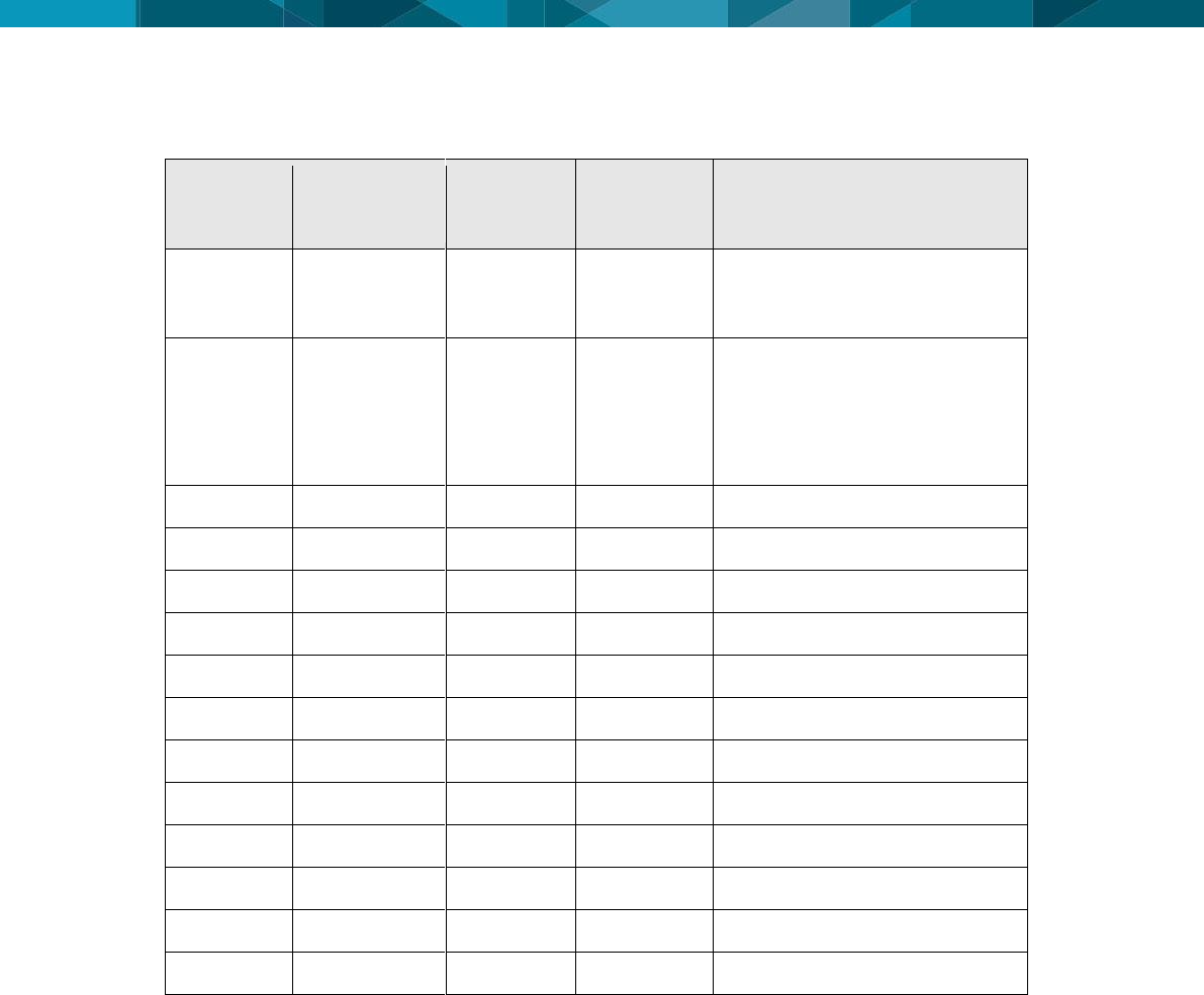
Revision History
Date
Document
Version
Hardware
Version
Author
Revision
09 AUG
2016
1
1.0
Gustavo
Henrique
L.Severino
Initial Document Release
15 JAN
2017
2
1.0
Gustavo
Henrique
L.Severino
Addition in the description of
items 2.2, 5.1.2, and 5.2.
Obsolescence of Ethernet
Input and Ethernet POE
Output ports.

© Leica Geosystems Commercial in Confidence iii
Table Of Contents
1 Document Introduction .............................................................................. 1
1.1 Contacting Support ...................................................................................................... 1
1.2 Document Conventions ................................................................................................ 1
2 HUB SM|UG Overview ................................................................................ 2
2.1 System Information ...................................................................................................... 2
2.2 Product Description ...................................................................................................... 2
2.3 LEDs............................................................................................................................. 3
2.4 Labels ........................................................................................................................... 3
2.4.1 HUB SM|UG Serial Number Label. .................................................................... 4
2.4.2 HUB SM|UG Complaince Label ......................................................................... 4
2.4.2.1 FCC Certification Label .............................................................................. 4
2.4.2.2 Anatel Certification Label ........................................................................... 4
2.4.2.3 Certification Label of Internal Transmitter Module ..................................... 4
2.4.3 Labels Location .................................................................................................. 5
2.4.3.1 Serial Number Label Locations .................................................................. 5
2.4.3.2 Certification Label Locations ...................................................................... 5
2.4.3.3 Label Location of Internal Transmitter Module .......................................... 6
3 Commissioning HUB SM|UG ..................................................................... 7
3.1 Commissioning Workflow ............................................................................................. 7
4 Hardware Installation ................................................................................. 8
4.1 Before Installation ........................................................................................................ 8
4.2 HUB SM|UG Installation ............................................................................................... 8
4.2.1 Front View .......................................................................................................... 9
4.2.2 Top View ............................................................................................................ 9
4.3 Power Cable Installation .............................................................................................. 9
4.4 Antenna Installations .................................................................................................. 10
4.4.1 Antenna Application ......................................................................................... 10
4.4.2 VHF Antenna Installation ................................................................................. 10
4.4.3 UHF Antenna Installation ................................................................................. 11
4.5 Communication Cable Installation ............................................................................. 12
4.5.1 Tracker360 ....................................................................................................... 12
4.5.2 Jasset ............................................................................................................... 12
5 Software Configuration ............................................................................ 13
5.1 Installation and Configuration Verification.................................................................. 13
5.1.1 Tag’s Reader ................................................................................................... 13
5.1.2 Integra Radio (VHF) ......................................................................................... 14
5.2 Integra radio Configuration ........................................................................................ 15
6 Technical Data .......................................................................................... 17
6.1 Design ........................................................................................................................ 17
6.1.1 User interface................................................................................................... 17
6.1.2 Dimensions ...................................................................................................... 17
6.1.3 Weight .............................................................................................................. 17
6.1.4 Power ............................................................................................................... 17
6.2 Envionmental Specifications ...................................................................................... 17
6.2.1 Temperature .................................................................................................... 17
6.2.2 Protection Against Water, Dust and Sand ....................................................... 17
6.2.3 Protection Against Vibration ............................................................................ 17
6.2.4 Humidity ........................................................................................................... 17
6.3 Communication Interfaces ......................................................................................... 17
6.4 Wireless Module Technical Data ............................................................................... 18

iv © Devex Mining
6.4.1 RFID Tag Reader ............................................................................................ 18
6.4.2 Leaky Feeder Radio ........................................................................................ 18
6.4.3 Antenna Technical Data .................................................................................. 18
6.4.3.1 Antena RFID ............................................................................................ 18
6.4.3.2 Antena Leaky Feeder .............................................................................. 18
6.5 FCC Statement (Applicable for U.S.)......................................................................... 18
6.5.1 Antenna Technical Data .................................................................................. 18
7 Glossary ................................................................................................... 19
© Leica Geosystems Commercial in Confidence 1
1 Document Introduction
The HUB SM|UG Technical Reference Manual is part of SmartMine|UG Documentation Suite.
This manual is intended to serve as a guide to the hardware and components of the HUB
SM|UG module. This manual provides all instructions required in order to operate the HUB
SM|UG product to a basic level. This manual provides an overview of the system together with
technical data and safety directions.
WARNING:
Operators must be aware of the physical surroundings of their equipment and
drive to conditions and mine requirements at all times.
It is assumed an operator using this manual is familiar with:
Site-specific safety procedures, Safe Work Procedures (SWPs) and Standard Operating
Procedures (SOPs).
Note:
The document uses generic images to show general layout and generic information
for various procedures. The site-specific screen layout, menu, and procedure
information may vary from what is displayed in the manual.
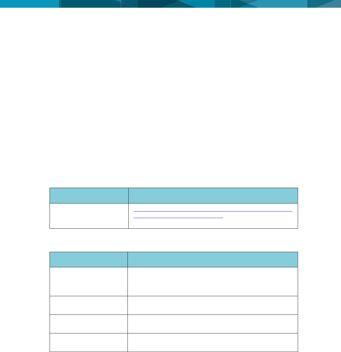
1.1 Contacting Support
For all Devex Mining product support:
Contact Method
Details
Web portal
http://www.hexagonmining.com/downloads/HxM_Active_Custo
mer_Care_Portal_Manual.V.01.pdf and Follow the steps of
document to support
1.2 Document Conventions
This document uses basic conventions to indicate actions:
Convention Example
Description
See xxx
Refer to
“See” indicates a reference to another section of this
document.
“Refer to” indicates reference to another document.
WARNING
Warnings alert the user to dangerous procedures which could
cause injury or death.
CAUTION
Cautions alert the user to dangerous procedures which could
cause damage to equipment.
Note
Notes supply important information about a procedure which is
not covered in the procedure text.
2 © Devex Mining
2 HUB SM|UG Overview
The HUB SM|UG is a communication and location interface that allows to a communication
between the mine’s asset and SmartMine|UG management system through Leaky Feeder.
2.1 System Information
Note:
The document uses generic images to show general layout and generic information
for various procedures. The site-specific screen layout, menu, and procedure
information may vary from what is displayed in the manual.
HUB SM|UG performs the following functions:
Convert serial information in RFID signals to reading of Tag's
Convert serial information in RF signals to exchange information with Leaky Feeder system.
HUB SM|UG software provides:
Intuitive set up and operation.
CaLAMP and Analyzer softwares configuration.
Upgrade through debug cable.
See Software Installation for more information
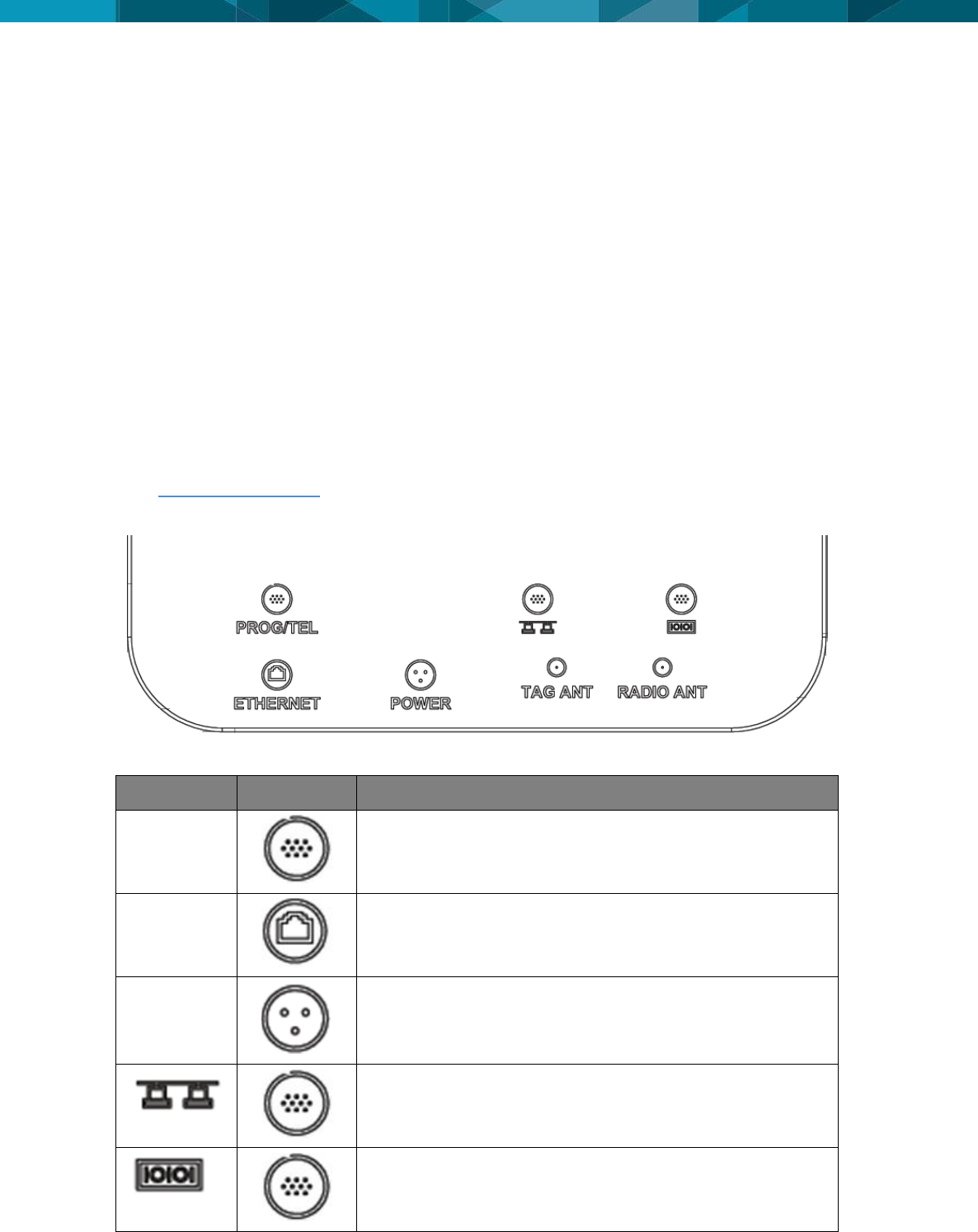
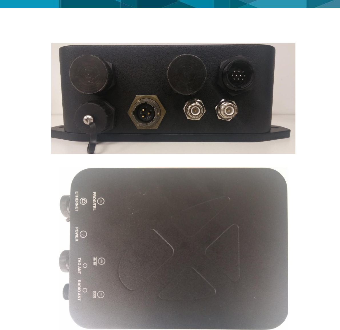
2.2 Product Description
The figure above shows the indication of the connections of the HUB SM|UG with details.
Description
Icon
Function
PROG/TEL
Radio Programming
ETHERNET
POE Ethernet Output – Obsolete port (Not Used)
POWER
Power Supply
Ethernet connection – Obsolete port (Not Used)
Serial input
© Leica Geosystems Commercial in Confidence 3
TAG ANT
RF signal of UHF Antenna
RADIO ANT
RF signal of VHF Antenna
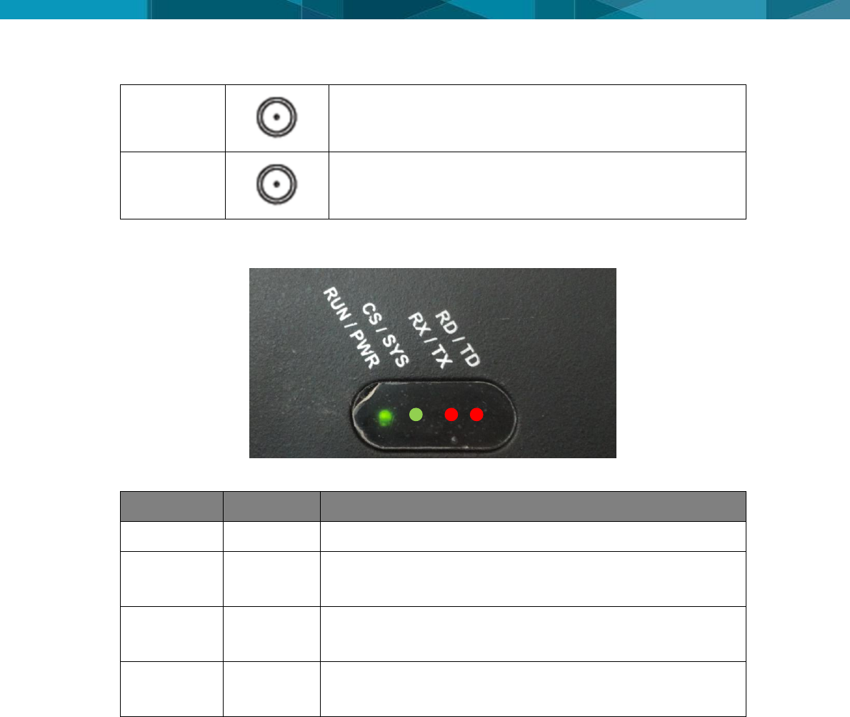
2.3 LEDs
Description
LED
Function
RUN/PWR
GREEN
Green LED light indicates the HUB SM|UG is powered
CS/SYS
GREEN
ORANGE
Green LED light indicates the radio is OK
Red LED light indicates the radio is being programmed
RX/TX
GREEN
RED
Green LED light indicates the radio is receiving date
Red LED light indicates the radio is transmitting date
RD/TD
GREEN
RED
Green LED light indicates the radio is receiving date
Red LED light indicates the radio is transmitting date
2.4 Labels
The HUB is composed by two labels: Identified label and compliance label.
The identified label indicate the product is compatible with the technologies adopted in country
and meets technical requirements of operation and warranty conditions, technical support and
quality.
The compliance label shows the origin, production batch, serial number and part number.
As the HUB SMUG has an internal module already certified, it must inform the module label, its
location and that Contains Transmitter Module FCC ID: NP444018450.
4 © Devex Mining
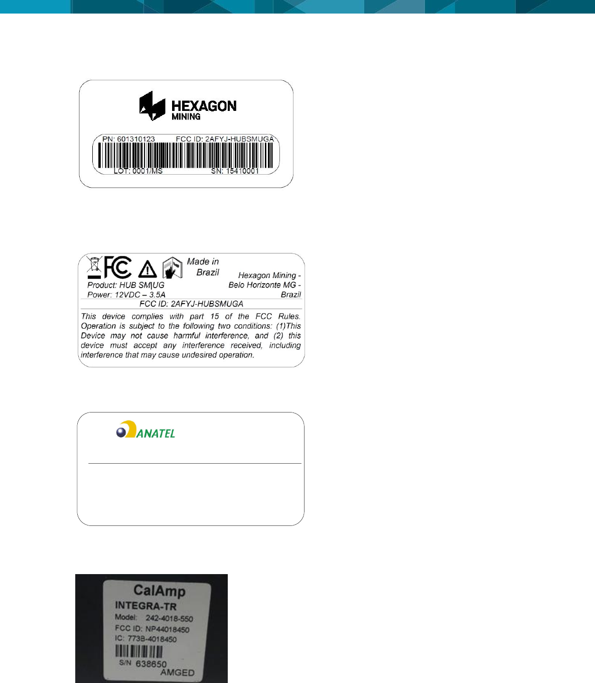
2.4.1 HUB SM|UG Serial Number Label.
2.4.2 HUB SM|UG Complaince Label
2.4.2.1 FCC Certification Label
(Used in countries adopting FCC as telecommunications standard)
2.4.2.2 Anatel Certification Label
(Used in Brazil)
Este equipamento opera em caráter secundário, isto é,
não tem direito a proteção contra interferência
prejudicial, mesmo de estações do mesmo tipo, e não
pode causar interferência a sistemas operando em
caráter primário
Product: HUB SM|UG
Power: 12VDC – 3.5A Hexagon Mining - Belo
Horizonte MG - Brazil
02424-16-04538
2.4.2.3 Certification Label of Internal Transmitter Module
Contains Transmitter Module FCC ID: NP444018450
© Leica Geosystems Commercial in Confidence 5
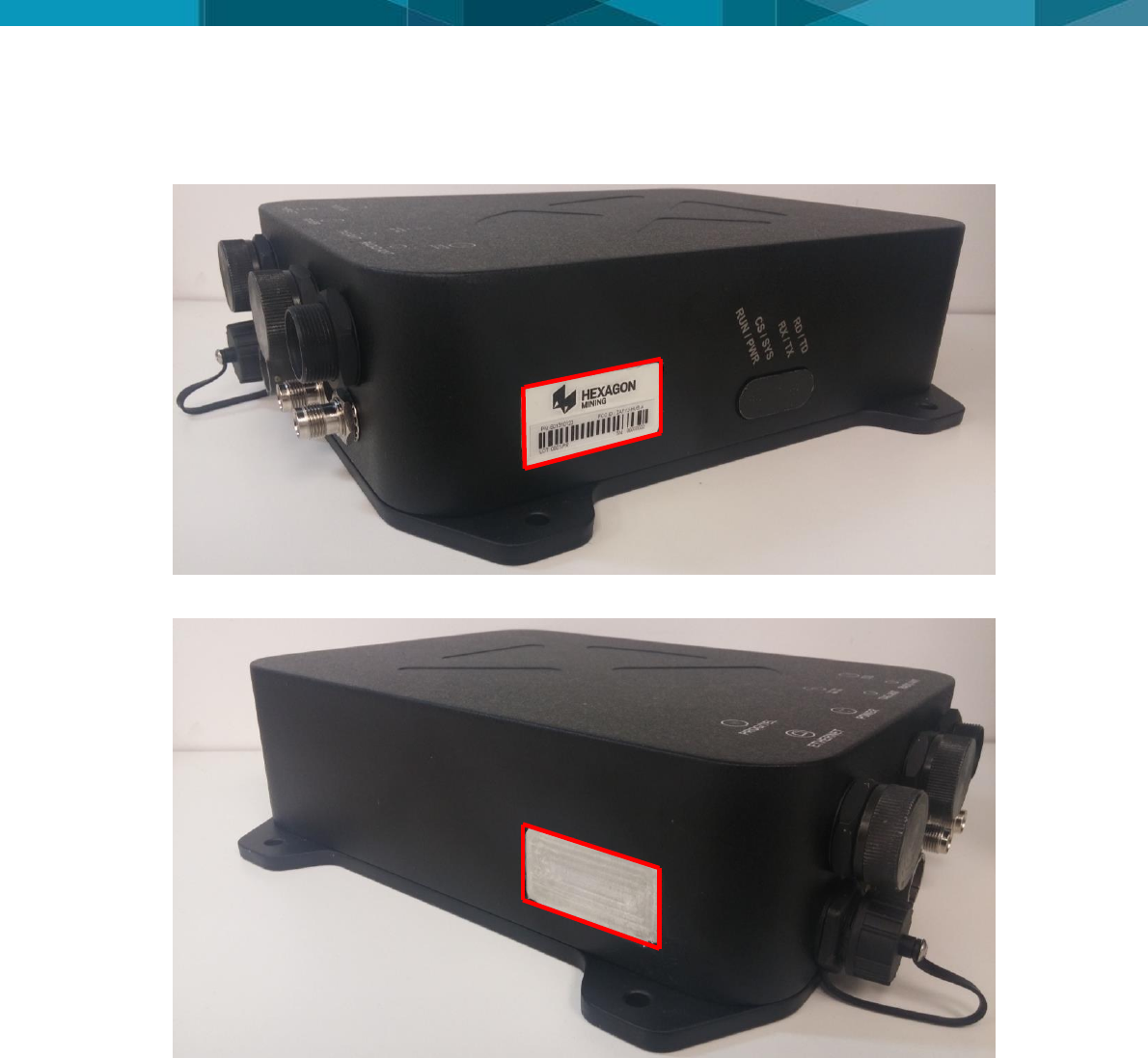
2.4.3 Labels Location
2.4.3.1 Serial Number Label Locations
2.4.3.2 Certification Label Locations
6 © Devex Mining
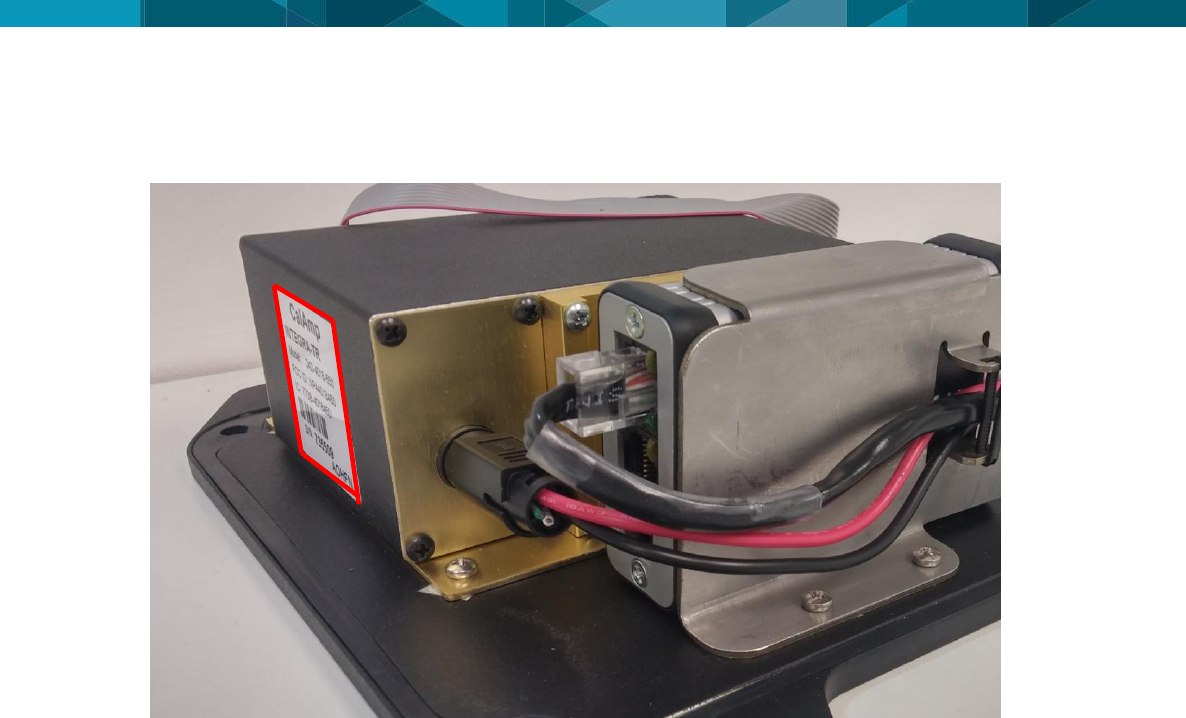
2.4.3.3 Label Location of Internal Transmitter Module

© Leica Geosystems Commercial in Confidence 7
3 Commissioning HUB SM|UG
3.1 Commissioning Workflow
1. See Chapter 4 Hardware Installation.
2. See Chapter 5 Software Installation.
8 © Devex Mining
4 Hardware Installation
4.1 Before Installation
Installation requires specialized knowledge and must be installed by a Hexagon Mining
Authorized Installer. Hexagon Mining recommends that installation of the HUB SM|UG
equipment be performed by a qualified technician because installation requires marking
electrical connections.
Install the system in a clean and workshop environment. Failure to do so may cause the
system to short or promote product malfunction.
Route and secure all cables and wiring to ensure that they not chafe or rub premature failure
The average installation time varies, but should take approximately one hour per asset. The
time of installation may be more, or less, based on asset type and options purchased.
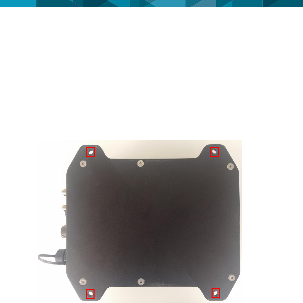
4.2 HUB SM|UG Installation
Select an appropriate place to mount the HUB SM|UG module.
Four mount holes are provided in the metal housing, these should be used to firmly mount
the UHP to the machine using the supplied bolt.
WARNING:
Do not mount the module where it may obscure the driver’s view of the road.
WARNING:
Do not mount the module where it may be struck by a deploying airbag.
© Leica Geosystems Commercial in Confidence 9
4.2.1 Front View
4.2.2 Top View
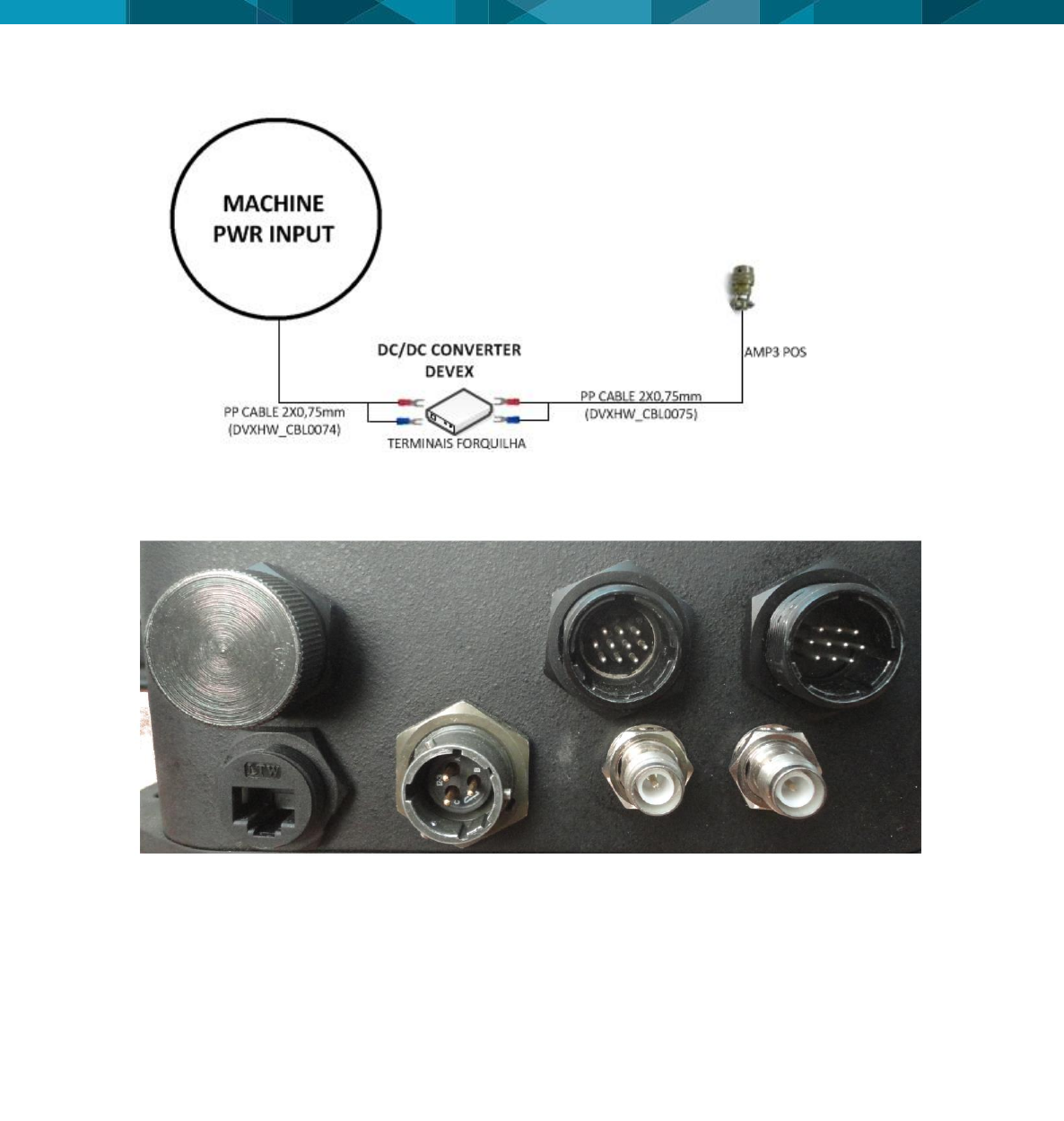
4.3 Power Cable Installation
1. Connect the supplied power cable of DC-DC Converter (Refer to: DVXHW_CBL0074) to a
reliable source, for example, the vehicle’s main power system
a. Connect the DC-DC converter to a 12 or 36-volt positive source capable of delivering a
constant current of 2 A.
b. Connect the black wire to the vehicle’s earth ground.
2. Connect the supplied power cable of HUB SM|UG to converter DC-DC (Refer to:
DVXHW_CBL0075 - Cabo Externo Alimentação – HUB). As shown below.
3. Connect the Installation Kit for Tracker+ according to the document DVXHW_RMT0027 –
Wiring Diagram – Installation Kit For Tracker+.
10 © Devex Mining
1. Route and secure all cables and wiring to ensure that there is no rubbing, which can cause
premature failure.
2. Connect the power cable to the Power connector on the front of the HUB SM|UG module.
4.4 Antenna Installations
4.4.1 Antenna Application
VHF
o ANTENA PHANTOM VHF 156-160
o Communication with Leaky Feeder
o Part Number Devex - 101030025
UHF
o ANTENA PHANTOM UHF 440 NMO BK
o Communication with TAG RFID
o Part Number Devex - 101030024
4.4.2 VHF Antenna Installation
Note:
Read all instructions prior to assembly and installation.
The HUB SM|UG module’s VHF Antenna must be mounted with a clear view of the sky and free
from any obstruction from machine components, and must meet the following criteria:
1. The HUB SM|UG module VHF Antenna must be on the flat level part of the machine or
mast.
POWER
CONNECTOR

© Leica Geosystems Commercial in Confidence 11
2. The HUB SM|UG module VHF Antenna must not be obstructed by exhausts, flashing lights,
masts, trays, or any other objects. It must be mounted such that it has an unobstructed view
of the sky and is as high on the equipment as possible.
3. The HUB SM|UG module VHF Antenna must not be mounted within 50 cm of any other
antenna.
4. Route the cables through bulkheads using the existing grommets if possible; if not,
modification may be required to route the cables to the required location. If creating a new
entry point, use a grommet to protect the cables.
5. The cables must not be cut, kinked, or bent tightly, as their performance degrades and a
system failure may result.
6. Route the cables back to the HUB SM|UG module.
7. If cables are not terminated, terminate the cable and check connectivity before connecting to
the antenna
8. A universal mounting magnetic base is provided to secure the VHF antenna.
9. Mount the VHF antenna with magnetic base cleaning the contact location prior to fixation.
10. Route the cable to the HUB SM|UG module and connect to TNC in the TAG ANT port.
4.4.3 UHF Antenna Installation
Note:
Read all instructions prior to assembly and installation.
The HUB SM|UG module’s UHF Antenna must be mounted with a clear view of the sky and free
from any obstruction from machine components, and must meet the following criteria:
1. The HUB SM|UG module UHF Antenna must be on the flat level part of the machine or
mast.
2. The HUB SM|UG module UHF Antenna must not be obstructed by exhausts, flashing lights,
masts, trays, or any other objects. It must be mounted such that it has an unobstructed view
of the sky and is as high on the equipment as possible.
3. The HUB SM|UG module UHF Antenna must not be mounted within 50 cm of any other
antenna.
4. Route the cables through bulkheads using the existing grommets if possible; if not,
modification may be required to route the cables to the required location. If creating a new
entry point, use a grommet to protect the cables.
5. The cables must not be cut, kinked, or bent tightly, as their performance degrades and a
system failure may result.
6. Route the cables back to the HUB SM|UG module.
7. If cables are not terminated, terminate the cable and check connectivity before connecting to
the antenna
8. A universal mounting magnetic base is provided to secure the UHF antenna.
9. Mount the UHF antenna with magnetic base cleaning the contact location prior to fixation.
10. Route the cable to the HUB SM|UG module and connect to TNC in the TAG ANT port.
12 © Devex Mining
4.5 Communication Cable Installation
4.5.1 Tracker360
Connect the communication cable TRACKER360_HUB (Refer to: DVXHW_CBL0145R03 -
TRACKER360_HUB - CABLE) to serial connector of HUB SM|UG (IOIOI) and to serial
connector of Tracker360 (POS) as show below.
4.5.2 Jasset
Connect the communication cable JASSET_HUB (Refer to: DVXHW_CBL0169R00 -
JASSET_HUB - CABLE) to serial connector of HUB SM|UG (IOIOI) and to serial connector of
Jasset (Automotive connector of 6 way) as show below.
© Leica Geosystems Commercial in Confidence 13
5 Software Configuration
The following procedure is used for software upgrades and checks of HUB SM|UG.
Note:
Contact Hexagon Mining for the required files.
5.1 Installation and Configuration Verification
Since the HUB SM|UG is already installed in the equipment must be done a check all set that is
connected to it.
In this step the following tests are described:
5.1.1. Tag’s Reader
5.1.2. Integra Radio(VHF)
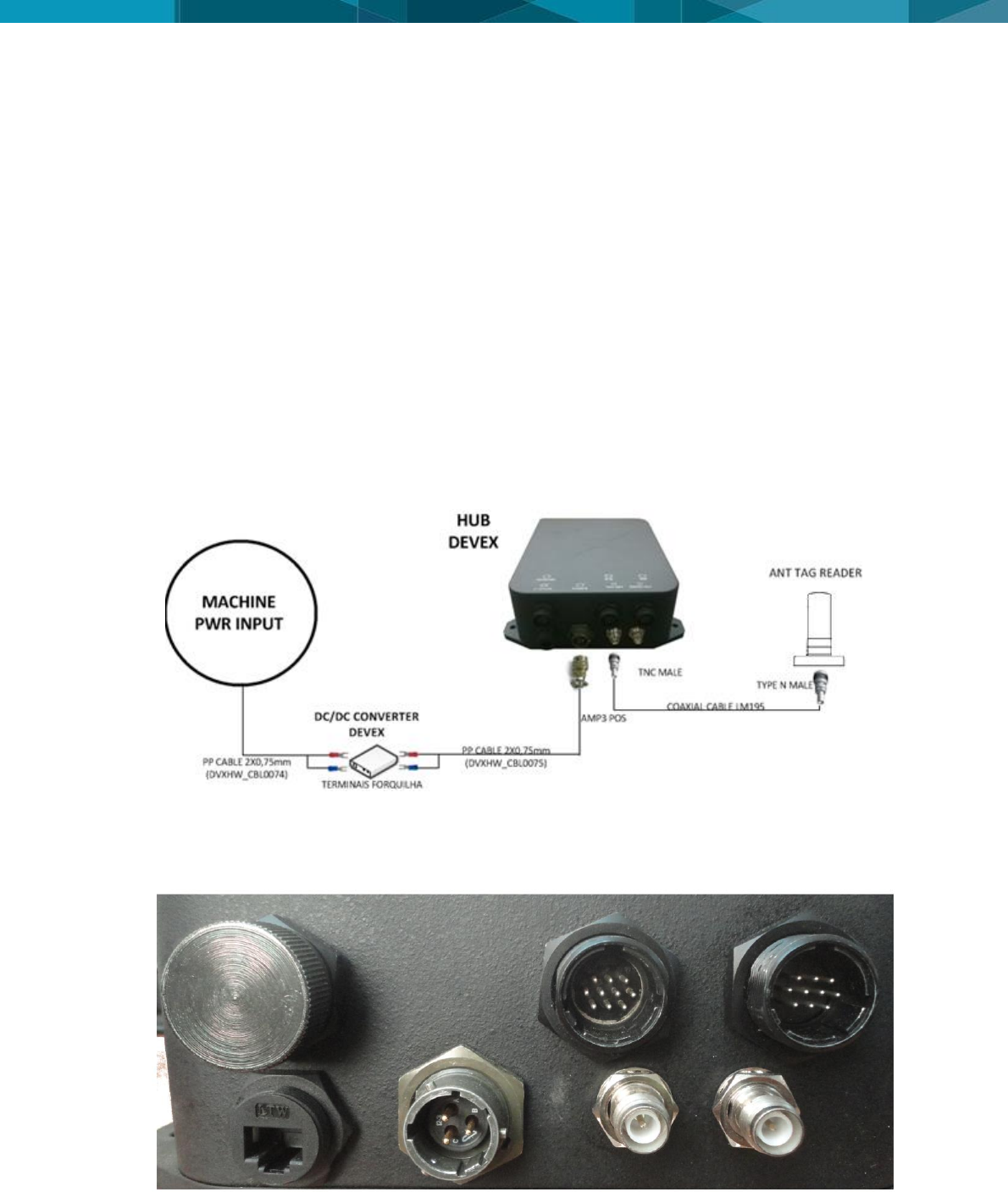
5.1.1 Tag’s Reader
To check the tag's reader test, the connection diagram part shown below will be tested.
For Tag Reading test should use the HUB SM|UG script for Tag’s Reader (Refer to:
DVXHW_TST0017), but must be connected to the tag antenna cable in the HUB for this test is
done. The Tag's reader antenna cable must be connected to the "ANT TAG" connector of HUB
as the following figure.
Must be performed all steps of DVXHW_TST0017 script, but must place a tag with known ID at
least five meters away from the equipment that tag reader antenna is able to read. With a
smaller distance, the tag's reader antenna will not be tested properly.
TAG
ANTENNA
14 © Devex Mining
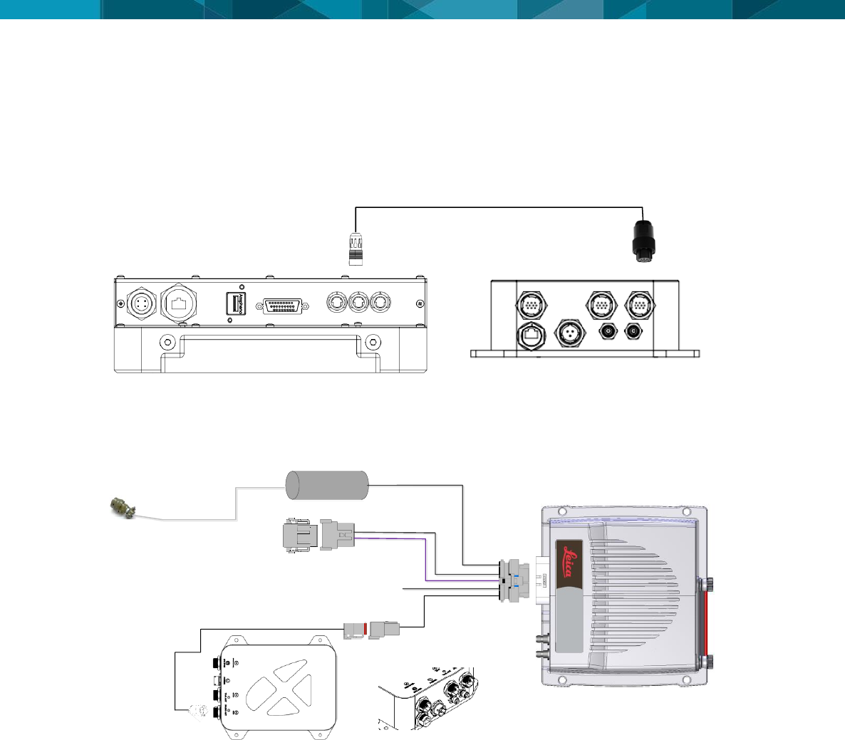
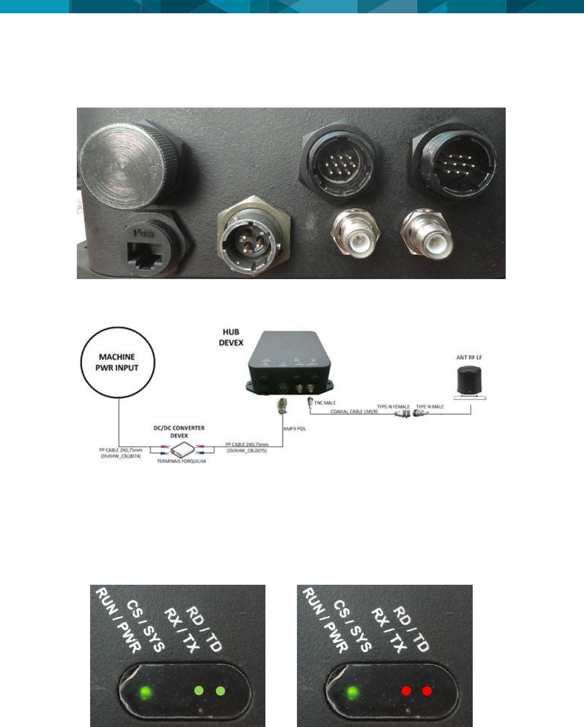
5.1.2 Integra Radio (VHF)
For the VHF radio test, besides the hub power supply must be connected also the radio VHF
antenna connector (ANT) as shown in below.
The components to be tested in this step of the test are shown in the figure below. In the Integra
radio test, it is not impossible for the RS232 Serial – Radio programming port to be functioning
during the radio operation in test and/or field.
For Integra radio test should use the HUB SM|UG script for Integra Radio (Refer to:
DVXHW_TST0018). Contact Hexagon Mining support for the required files of the Integra Radio.
It should be remembered that after the radio programming must be placed the connector
protective cover shown in the above.
After the test verification, may also be noted the communication by the HUB SM|UG display, the
LEDs indicated as RX/TX and RD/TD illuminate almost simultaneously in green when a data is
received by VHF radio and in red color when a data is sent. This can facilitate the diagnosis of
communication if it has any problems with the radio test. The colors of the radio LEDs as its
state of communication are represented in the following figures.
Reception (green LEDs) and Transmission (red LED) of data - VHF radio
RADIO
ANTENNA
© Leica Geosystems Commercial in Confidence 15
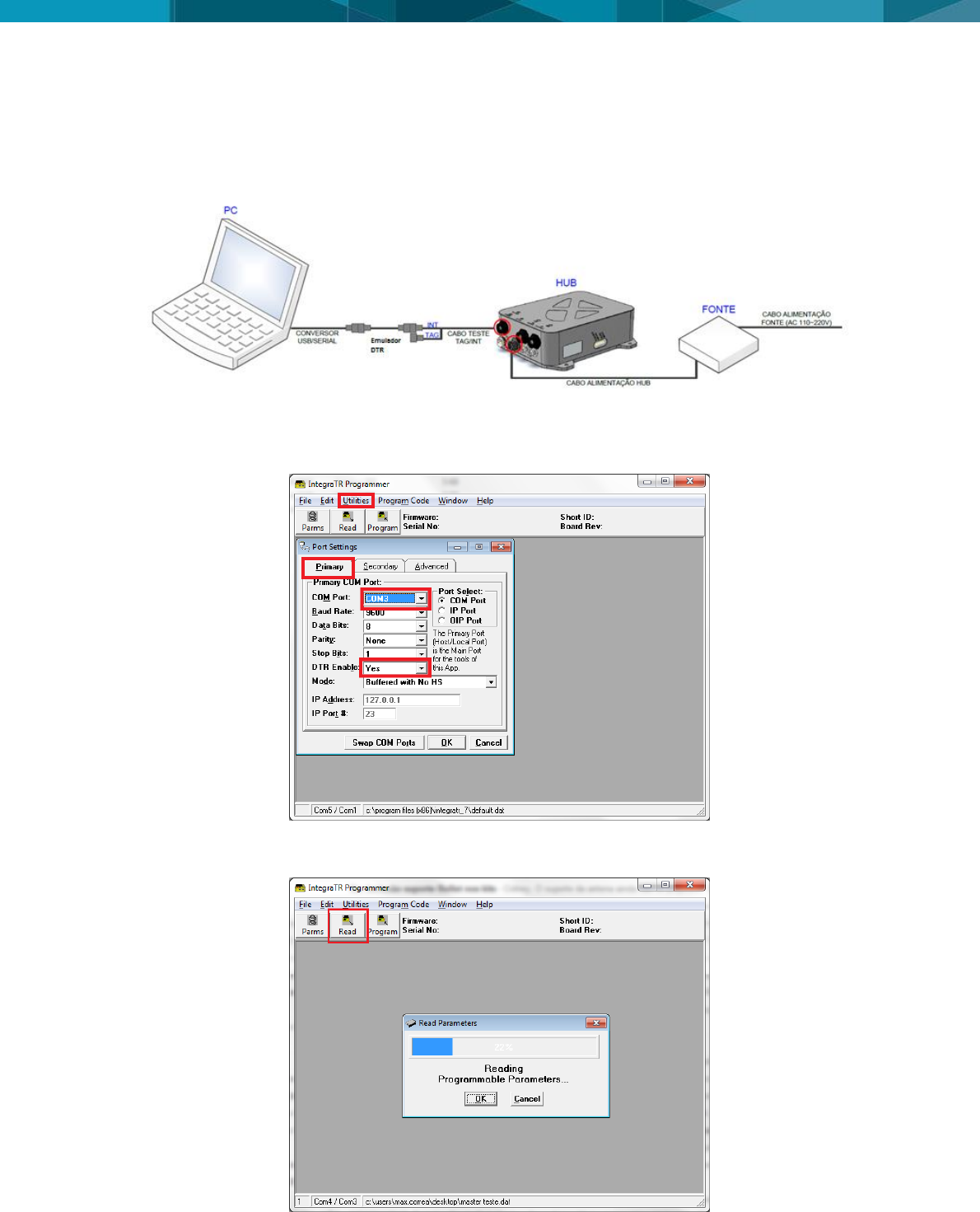
5.2 Integra radio Configuration
Below can be seen the connection diagram, for configure Integra radio. In the configuration
procedure of Integra radio, it is not impossible for the RS232 Serial – Radio communication port
to be functioning during the radio configuration.
Run the program “INTEGRA CALLAMP” and configure the serial port that is being used. Click in
“Ultilities>Port Settings” in Primary tab and select the port that was identified and select “YES” in
DTR enable options, click OK.
After the port configuration, the program should recognize the radio used and its configuration.
Click "Read" and waits for the complete program.
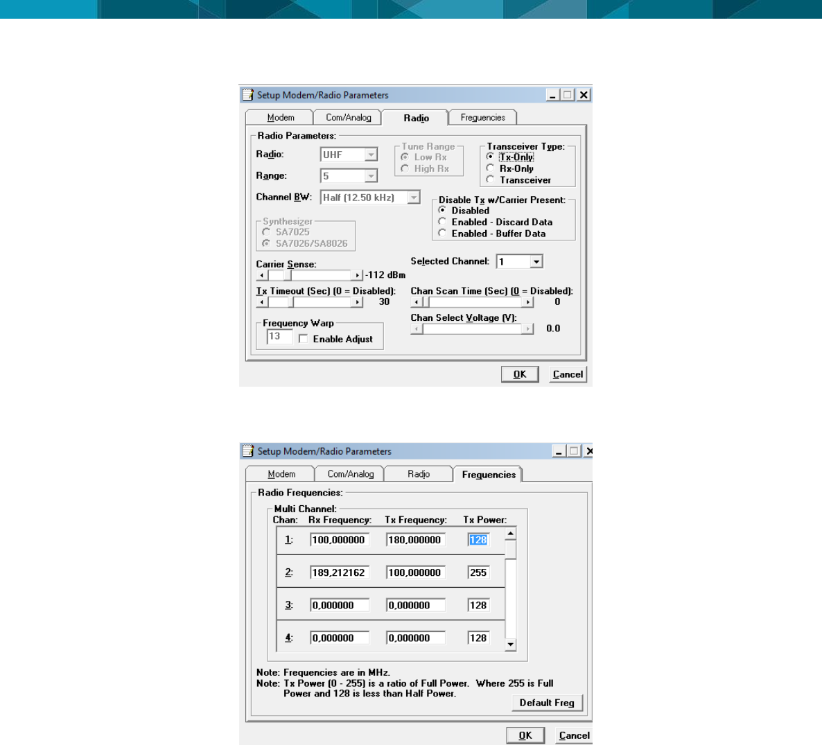
After reading the parameters click “Parms” and waits for the radio setup screen.
16 © Devex Mining
In “Radio” tab, we can configure the “transceiver Type” mode as “Transceiver”. In “Frequencies”
tab, we can configure the power in item “TX power”, according to figure below: The frequencies
used are the same used in the Leaky Feeder, but the TX and RX must be exchanged.
© Leica Geosystems Commercial in Confidence 17
6 Technical Data
6.1 Design
Industrial metal housing
6.1.1 User interface
Console RS-232 serial
6.1.2 Dimensions
Length (cm)
Width (cm)
Height (cm)
22,50
26,58
7,55
6.1.3 Weight
Weight (Kg)
3
6.1.4 Power
Consumption
External Supply Voltage
42 W
Voltage 12 VDC
6.2 Envionmental Specifications
6.2.1 Temperature
Operating Temperature (ºC)
Storage Temperature (ºC)
-20 a +60
-30 a +70
6.2.2 Protection Against Water, Dust and Sand
Protection
IP65
6.2.3 Protection Against Vibration
Protection
The tests were done according
to the international standard
EN 600068-2-64
6.2.4 Humidity
Protection
5% a 90%
6.3 Communication Interfaces
Communication Interface
name
Quantity

18 © Devex Mining
RS-232 Serial - TAG Reader
1x
RS232 Serial – Radio
communication
1x
RS232 Serial – Radio
programming
1x
Ethernet POE Output
1x - Obsolete port (Not Used)
Ethernet Input
1x - Obsolete port (Not Used)
6.4 Wireless Module Technical Data
6.4.1 RFID Tag Reader
UHF – Frequency 433.92 MHz
6.4.2 Leaky Feeder Radio
VHF – Frequency - 136-162 MHz e 148-174 MHz
Maximum Transmission Power - 36dbm
6.4.3 Antenna Technical Data
6.4.3.1 Antena RFID
Frequency: 430 - 450 MHz
Gain: 3 dBi
6.4.3.2 Antena Leaky Feeder
Frequency: 156-172 MHz
LNA Gain: 2.15 dB
6.5 FCC Statement (Applicable for U.S.)
This equipment has been tested and found to comply with the limits for a Class A digital device,
pursuant to part 15 of the FCC Rules. These limits are designed to pro-vide reasonable
protection against harmful interference when the equipment is operated in a commercial
environment. This equipment generates, uses, and can radiate radio frequency energy and, if
not installed and used in accordance with the instruction manual, may cause harmful
interference to radio communications. Operation of this equipment in a residential area is likely
to cause harmful interference in which case the user will be required to correct the interference
at his own expense.
6.5.1 Antenna Technical Data
© Leica Geosystems Commercial in Confidence 19
7 Glossary
Term
Definition
DC
Direct Current
FCC
Federal Communications Commission
HUB SM|UG
HUB SmartMine Underground
IP
Protection Index
LED
Light Emitting Diode
POE
Power Over Ethernet
RFID
Radio-Frequency IDentification
RF
Radio Frequency
VCD
Voltage current continue
VHF
Very High Frequency
SOPs
Standard Operating Procedures
SWPs
Safe Work Procedures
USB
Universal Serial Bus
UHF
Ultra High Frequency

Hexagon Mining is the only company to solve surface and underground challenges by integrating design,
planning, and operations technologies for safer, more productive mines. Headquartered in Tucson, Arizona,
with more than 30 offices across five continents, the company is a dynamic network of talented mining
professionals delivering technology, service, and support.
Hexagon Mining unites industry leaders MineSight, Devex Mining, Leica Geosystems Mining, and
SAFEmine. Together they seamlessly link mine planning, design, fleet and production management,
optimization, and collision avoidance software for a comprehensive flow of data across all operations. Learn
more at hexagonmining.com.
Hexagon Mining is part of Hexagon (Nasdaq Stockholm: HEXA B; www.hexagon.com), a leading global
provider of information technologies that drive quality and productivity improvements across geospatial and
industrial enterprise applications.
For more information, visit;
Website: www.hexagonmining.com
Twitter: @HexagonMining