Hexagon Mining JASSET Equipment Locator and Communication Hub User Manual Leica Jasset User Reference Manual Software v2 07
Leica Geosystems Equipment Locator and Communication Hub Leica Jasset User Reference Manual Software v2 07
Manual
Version No. 4.0
Issued February 2016 English
Leica Jasset
User Reference Manual
Software v2.07
Commercial in Confidence
© Leica Geosystems
Leica Jasset User Reference Manual
This document and any information or descriptive matter contained therein is communicated
in confidence and is the copyright property of Leica Geosystems. Neither the whole, nor any
extract may be disclosed, loaned, copied, or used in manufacturing or tendering purposes
without their written consent.
© Copyright [2014-2016] Leica Geosystems Pty Ltd. All rights reserved. Leica Geosystems
Pty Ltd is part of Hexagon. Leica Geosystems and the Leica Geosystems logo are the
registered trademarks of Leica Geosystems. All trademarks or service marks used herein are
property of their respective owners. Leica Geosystems makes no representation or warranty
regarding the accuracy of the information in this publication. This document gives only a
general description of the product(s) or service(s) offered by Leica Geosystems and, except
where expressly provided otherwise, shall not form part of any contract. Such information,
the products and conditions of supply is subject to change without notice.
Disclaimer: Illustrations, descriptions, and technical specifications in this document are not
binding and are subject to change without notice.
Printing is optimized for A4 paper.

Commercial in Confidence
© Leica Geosystems
i
Revision History
Date
Document
Version
Software
Version
Author
Revision
24 Nov
2014
1
2.05
Dwayne Martine,
M.A. Martin
Initial Document Release
16 Jan
2015
1
2.06
Dwayne Martine,
M.A. Martin
Jasset Release Update
30
March
2015
1.2
2.06
M.A.Martin
Jasset update. Corporate format
change.
21 Aug
2015
1.3
2.06
M.A. Martin
Revised Cellular Antenna distance
from humans from 20 cm to 30 cm.
20 Jan
2016
3.0
2.07
P.Brighouse
Revised procedures for maintaining
an asset’s attributes and managing
a stationary asset, added engine
hours support, and made minor
corrections. Issued as v3.0 for
consistency with internal URM.
25 Jul
2016
4.0
2.07
M.A. Martin
Add US FCC compliance labels and
updated safety information in
sections:
2.3 Labels: Updated FCC
certification label.
2.3.3 Jasset Serial Number Labels:
Added United States (US)-specific
serial number labels.
4.4 Antenna Installations: Added
Installation Warning.
4.4.3 Wi-Fi Antenna Installation:
Updated antenna distance from
human statement.
4.4.3 Cellular Antenna Installation:
Updated antenna distance from
human statement.
9.4.3 Persons in Charge of the
Product: Added antenna safety
information
Added
Chapter 13: Appendix C Jasset FCC
Maximum Personal Exposure (MPE)
Calculations
Updated inside front cover to
corporate requirements.
Commercial in Confidence
© Leica Geosystems
ii
Table Of Contents
1 Document Introduction ................................................ 1
System Installation ........................................................................................................... 1 1.1
Contacting Support .......................................................................................................... 1 1.2
Document Conventions .................................................................................................... 1 1.3
2 Jasset Overview .......................................................... 2
System Information .......................................................................................................... 2 2.1
2.1.1 Jasset W (Single Wi-Fi) ................................................................................................ 3
2.1.1.1 Jasset W Components ............................................................................................. 3
2.1.1.2 Jasset W Hardware .................................................................................................. 3
2.1.1.3 Jasset W Features and Specifications ..................................................................... 4
2.1.2 Jasset WW (Dual Wi-Fi) ............................................................................................... 5
2.1.2.1 Jasset WW Components .......................................................................................... 5
2.1.2.2 Jasset WW Hardware .............................................................................................. 5
2.1.2.3 Jasset WW Features and Specifications ................................................................. 6
2.1.3 Jasset G (Cellular Communication – No Wi-Fi) ........................................................... 7
2.1.3.1 Jasset G Components .............................................................................................. 7
2.1.3.2 Jasset G Hardware................................................................................................... 7
2.1.3.3 Jasset G Features and Specifications ..................................................................... 8
2.1.4 Jasset WG (Single Wi-Fi and Cellular Communication) .............................................. 9
2.1.4.1 Jasset WG Components .......................................................................................... 9
2.1.4.2 Jasset WG Hardware ............................................................................................... 9
2.1.4.3 Jasset WG Features and Specifications ................................................................ 10
2.1.5 Jasset WWG (Dual Wi-Fi and Cellular Communication)............................................ 11
2.1.5.1 Jasset WWG Components ..................................................................................... 11
2.1.5.2 Jasset WWG Hardware .......................................................................................... 11
2.1.5.3 Jasset WWG Features and Specifications ............................................................. 12
Product Faceplate Description ....................................................................................... 13 2.2
2.2.1 Faceplate Decals........................................................................................................ 13
2.2.2 LEDs ........................................................................................................................... 14
2.2.3 Connector Icons ......................................................................................................... 15
Labels ............................................................................................................................. 16 2.3
2.3.1 Label Locations .......................................................................................................... 16
2.3.2 Jasset FCC Certification Label ................................................................................... 16
2.3.3 Jasset Serial Number Labels ..................................................................................... 17
3 Jasset Commissioning .............................................. 18
Commissioning Workflow ............................................................................................... 18 3.1
4 Hardware Installation ................................................ 19
Before Installation .......................................................................................................... 19 4.1
Jasset Module Installation .............................................................................................. 19 4.2
4.2.1 Jasset Mounting Accessories ..................................................................................... 19
4.2.1.1 Mounting Plates...................................................................................................... 19
4.2.1.2 Pole Mount ............................................................................................................. 20
4.2.1.3 Vertical Mount ........................................................................................................ 20
4.2.1.4 Flat Mount .............................................................................................................. 20
4.2.1.5 Mojo Adapter Plate ................................................................................................. 21
4.2.2 Magnetic Mounting ..................................................................................................... 21
4.2.2.1 Magnetic Installation .............................................................................................. 22
4.2.2.2 Magnetic Mount Removal ...................................................................................... 23
Power Cable Installation ................................................................................................ 23 4.3
Antenna Installations ...................................................................................................... 24 4.4
4.4.1 Antenna Application ................................................................................................... 24
Commercial in Confidence
© Leica Geosystems
iii
4.4.2 GNSS Antenna Installation ......................................................................................... 24
4.4.3 Wi-Fi Antenna Installation ........................................................................................... 25
4.4.4 Cellular Antenna Installation ....................................................................................... 26
SIM Card Installation – Jasset G, WG, and WWG ......................................................... 26 4.5
5 Software Installation .................................................. 28
Update Leica Jasset Software using USB Flash Drive .................................................. 28 5.1
Configure Leica Jasset ................................................................................................... 29 5.2
Installation and Configuration Verification ...................................................................... 31 5.3
6 Leica Jmineops Jasset Office Administration ........... 32
Asset Icon ....................................................................................................................... 32 6.1
6.1.1 Available Asset Icons .................................................................................................. 32
6.1.2 Asset Proximity Ring ................................................................................................... 32
6.1.3 Leica Jasset Representation on the Mine Map .......................................................... 33
Jmineops Asset View...................................................................................................... 33 6.2
6.2.1 Access Asset View from Jmineops ............................................................................. 34
6.2.2 Change an Asset’s Attributes ..................................................................................... 35
6.2.2.1 Change Asset Type ................................................................................................ 35
6.2.3 Change Status and Activity ........................................................................................ 36
Leica Jmineops Equipment Operations .......................................................................... 37 6.3
Leica Jasset on the Mine Map Application ..................................................................... 38 6.4
6.4.1 Enable Jasset Layer on Mine Map ............................................................................. 38
6.4.2 Find a Jasset on the Jmineops Mine Map .................................................................. 39
6.4.3 Filter Assets on Mine Map by Asset Type .................................................................. 40
6.4.4 Access Jmineops Asset View from Mine Map ............................................................ 41
6.5 Update an Asset’s Equipment Attributes ........................................................................ 42
Create and Maintain a Stationary Asset ......................................................................... 42 6.6
6.6.1 Create a Stationary Asset ........................................................................................... 43
6.6.2 Change Position of a Stationary Asset on Mine Map ................................................. 43
View Jasset using Shift State View ................................................................................ 44 6.7
6.7.1 View Jasset by Shift Status ........................................................................................ 45
Set Update Timing (Low Power Mode)........................................................................... 48 6.8
6.9 Manage Engine Hours .................................................................................................... 48
Monitor Asset Overspeed Alerts ..................................................................................... 48 6.10
Jasset on Jsplayback...................................................................................................... 49 6.11
Jmineops Asset Status and Activity History Gantt Chart View ....................................... 50 6.12
6.12.1 Access Status and Activity Gantt View ....................................................................... 50
6.12.1.1 Status and Activity Gantt View ............................................................................... 51
6.12.2 Load Data to Gantt View............................................................................................. 54
6.12.3 View Gantt Details ...................................................................................................... 57
6.12.4 Vertical Time Gridlines ................................................................................................ 57
6.12.5 Gantt Legend .............................................................................................................. 58
6.12.6 View, Edit, or Delete Data Detail on the Gantt View .................................................. 58
6.12.6.1 View Data Detail ..................................................................................................... 58
6.12.6.2 Data Detail View ..................................................................................................... 59
6.12.6.3 Edit Data Detail ....................................................................................................... 62
6.12.6.4 Insert Data .............................................................................................................. 63
6.12.6.5 Delete Data ............................................................................................................. 64
Asset Alarms ................................................................................................................... 64 6.13
7 Leica Jview Jasset Reports ...................................... 65
Jasset Inventory Report .................................................................................................. 65 7.1
Jasset Status Report ...................................................................................................... 67 7.2
Commercial in Confidence
© Leica Geosystems
iv
7.2.1 Duration Bar Graph .................................................................................................... 68
7.2.2 Pie Chart .................................................................................................................... 68
Jasset Dashboard .......................................................................................................... 69 7.3
8 Care and Transport ................................................... 70
Transport ........................................................................................................................ 70 8.1
Storage ........................................................................................................................... 70 8.2
Cleaning and Drying ....................................................................................................... 70 8.3
8.3.1.1 Product and Accessories ....................................................................................... 70
8.3.1.2 Connectors and Plugs ............................................................................................ 70
9 Safety Directions ....................................................... 71
General Introduction ....................................................................................................... 71 9.1
Intended Use .................................................................................................................. 71 9.2
9.2.1 Permitted Uses ........................................................................................................... 71
9.2.2 Adverse Use ............................................................................................................... 71
Limits of Use................................................................................................................... 71 9.3
9.3.1 Environment ............................................................................................................... 71
Responsibilities .............................................................................................................. 72 9.4
9.4.1 Manufacturer of the Product ....................................................................................... 72
9.4.2 Manufacturers of Non-Leica Geosystems Mining Accessories ................................. 72
9.4.3 Persons in Charge of the Product .............................................................................. 72
Hazards of Use............................................................................................................... 72 9.5
9.5.1 General Hazards ........................................................................................................ 72
9.5.2 Mechanical Hazards ................................................................................................... 72
9.5.3 Lightning Hazards ...................................................................................................... 73
9.5.3.1 Lightning Conductors ............................................................................................. 73
9.5.4 Disposal ...................................................................................................................... 74
Electromagnetic Compatibility (EMC) ............................................................................ 74
9.6
10 Technical Data .......................................................... 75
Jasset W (Single Wi-Fi) Technical Data ........................................................................ 75 10.1
10.1.1 Design ........................................................................................................................ 75
10.1.1.1 User Interface ......................................................................................................... 75
10.1.1.2 Dimensions ............................................................................................................. 75
10.1.1.3 Weight .................................................................................................................... 75
10.1.1.4 Power ..................................................................................................................... 75
10.1.2 Environmental Specifications ..................................................................................... 75
10.1.2.1 Temperature ........................................................................................................... 75
10.1.2.2 Protection Against Water, Dust, and Sand ............................................................ 75
10.1.2.3 Humidity ................................................................................................................. 75
10.1.3 Interfaces .................................................................................................................... 75
10.1.4 Wireless Module Technical Data ................................................................................ 76
10.1.4.1 Wi-Fi Module Technical Data ................................................................................. 76
10.1.5 Antenna Technical Data ............................................................................................. 76
10.1.5.1 Wi-Fi Antenna ......................................................................................................... 76
10.1.5.2 GNSS Antenna ....................................................................................................... 76
10.1.6 FCC Statement (Applicable for U.S.) ......................................................................... 76
Jasset WW (Dual Wi-Fi) Technical Data ........................................................................ 76 10.2
10.2.1 Design ........................................................................................................................ 76
10.2.1.1 User Interface ......................................................................................................... 76
10.2.1.2 Dimensions ............................................................................................................. 76
10.2.1.3 Weight .................................................................................................................... 77
10.2.1.4 Power ..................................................................................................................... 77
10.2.2 Environmental Specifications ..................................................................................... 77
Commercial in Confidence
© Leica Geosystems
v
10.2.2.1 Temperature ........................................................................................................... 77
10.2.2.2 Protection Against Water, Dust, and Sand ............................................................. 77
10.2.2.3 Humidity .................................................................................................................. 77
10.2.3 Interfaces .................................................................................................................... 77
10.2.4 Wireless Module Technical Data ................................................................................ 78
10.2.4.1 Wi-Fi Module Technical Data ................................................................................. 78
10.2.5 Antenna Technical Data ............................................................................................. 78
10.2.5.1 Wi-Fi Antenna ......................................................................................................... 78
10.2.5.2 GNSS Antenna ....................................................................................................... 78
10.2.6 FCC Statement (Applicable for U.S.) .......................................................................... 78
Jasset G (Cellular) Technical Data ................................................................................. 78 10.3
10.3.1 Design ......................................................................................................................... 78
10.3.1.1 User Interface ......................................................................................................... 78
10.3.1.2 Dimensions ............................................................................................................. 78
10.3.1.3 Weight ..................................................................................................................... 79
10.3.1.4 Power ...................................................................................................................... 79
10.3.2 Environmental Specifications ..................................................................................... 79
10.3.2.1 Temperature ........................................................................................................... 79
10.3.2.2 Protection Against Water, Dust, and Sand ............................................................. 79
10.3.2.3 Humidity .................................................................................................................. 79
10.3.3 Interfaces .................................................................................................................... 79
10.3.4 Wireless Module Technical Data ................................................................................ 79
10.3.4.1 LTE/HSPA+/GPRS Wireless Module Technical Data ............................................ 79
10.3.5 Antenna Technical Data ............................................................................................. 80
10.3.5.1 Cellular Antenna Technical Data ............................................................................ 80
10.3.5.2 GNSS Antenna ....................................................................................................... 80
10.3.6 Conformity to National Regulations for Jasset G Variant ........................................... 80
10.3.7 FCC Statement (Applicable for U.S.) .......................................................................... 80
Jasset WG (Single Wi-Fi and Cellular) Technical Data .................................................. 80 10.4
10.4.1 Design ......................................................................................................................... 80
10.4.1.1 User Interface ......................................................................................................... 80
10.4.1.2 Dimensions ............................................................................................................. 81
10.4.1.3 Weight ..................................................................................................................... 81
10.4.1.4 Power ...................................................................................................................... 81
10.4.2 Environmental Specifications ..................................................................................... 81
10.4.2.1 Temperature ........................................................................................................... 81
10.4.2.2 Protection Against Water, Dust, and Sand ............................................................. 81
10.4.2.3 Humidity .................................................................................................................. 81
10.4.3 Interfaces .................................................................................................................... 81
10.4.4 Wireless Module Technical Data ................................................................................ 81
10.4.4.1 Wi-Fi Module Technical Data ................................................................................. 81
10.4.4.2 LTE/HSPA+/GPRS Wireless Module Technical Data ............................................ 82
10.4.5 Antenna Technical Data ............................................................................................. 82
10.4.5.1 Wi-Fi Antenna ......................................................................................................... 82
10.4.5.2 Cellular Antenna Technical Data ............................................................................ 82
10.4.5.3 GNSS Antenna ....................................................................................................... 82
10.4.6 Conformity to National Regulations for Jasset G Variant ........................................... 82
10.4.7 FCC Statement (Applicable for U.S.) .......................................................................... 82
Jasset WWG (Dual Wi-Fi and Cellular) Technical Data ................................................. 83 10.5
10.5.1 Design ......................................................................................................................... 83
10.5.1.1 User Interface ......................................................................................................... 83
10.5.1.2 Dimensions ............................................................................................................. 83
10.5.1.3 Weight ..................................................................................................................... 83
10.5.1.4 Power ...................................................................................................................... 83
10.5.2 Environmental Specifications ..................................................................................... 83
10.5.2.1 Temperature ........................................................................................................... 83
Commercial in Confidence
© Leica Geosystems
vi
10.5.2.2 Protection Against Water, Dust, and Sand ............................................................ 83
10.5.2.3 Humidity ................................................................................................................. 83
10.5.3 Interfaces .................................................................................................................... 84
10.5.4 Wireless Module Technical Data ................................................................................ 84
10.5.4.1 Wi-Fi Module Technical Data ................................................................................. 84
10.5.4.2 LTE/HSPA+/GPRS Wireless Module Technical Data ............................................ 84
10.5.5 Antenna Technical Data ............................................................................................. 84
10.5.5.1 Wi-Fi Antenna ......................................................................................................... 84
10.5.5.2 Cellular Antenna Technical Data ............................................................................ 84
10.5.5.3 GNSS Antenna ....................................................................................................... 84
10.5.6 Conformity to National Regulations for Jasset G Variant .......................................... 84
10.5.7 FCC Statement (Applicable for U.S.) ......................................................................... 85
11 Appendix A – Universal Antenna Bracket ................. 86
12 Appendix B – Back Up Power Supply ....................... 87
Solar Panel Calculations - Using BP Solar Application ................................................. 88 12.1
12.1.1 Battery Size ................................................................................................................ 88
13 Appendix C - Jasset FCC Maximum Personal
Exposure (MPE) Calculations ............................................. 90
Jasset Intentional Radiators ........................................................................................... 90 13.1
13.1.1 Wi-Fi ........................................................................................................................... 90
13.1.2 4G ............................................................................................................................... 90
MPE Calculations ........................................................................................................... 90 13.2
13.2.1 WiFi MPE Calculations ............................................................................................... 90
13.2.2 4G MPE Calculations ................................................................................................. 90
14 Glossary .................................................................... 92

Commercial in Confidence
© Leica Geosystems
1
1 Document Introduction
The Leica Jasset User Reference Manual is part of Leica’s Fleet Management System (FMS)
Documentation Suite. This manual is intended to serve as a guide to the hardware and
components of the Jasset module. This manual provides all instructions required in order to
operate the Jasset product to a basic level. This manual provides an overview of the system
together with technical data and safety directions.
WARNING:
Operators must be aware of the physical surroundings of their equipment and
drive to conditions and mine requirements at all times.
It is assumed a user using this manual is familiar with:
Site-specific safety procedures, Safe Work Procedures (SWPs) and Standard Operating
Procedures (SOPs).
Mine operations.
Note:
The document uses generic images to show general layout and generic information
for various procedures. The site-specific screen layout, menu, and procedure
information may vary from what is displayed in the manual.
System Installation 1.1
WARNING:
This is a Class A product. In a domestic environment this product may cause
radio interference in which case the user may be required to take adequate
measures.
Leica Jasset must be professionally installed by Hexagon Mining trained installers. For installation
information see Hardware Installation.
Contacting Support 1.2
For all Leica Jigsaw product support:
Contact Method
Details
Web portal
http://www.hexagonmining.com/customer-portal.htm and
select OPERATIONS SUPPORT.
Document Conventions 1.3
This document uses basic conventions to indicate actions:
Convention Example
Description
Select FILE > PRINT
Menu selections, buttons, and icons appear in bold text. In this
case, select the FILE menu and the PRINT option. Location and
capitalization of menu items may vary by mine site.
Ctrl+P
Keyboard shortcut keys. The example indicates to select and hold
down the Ctrl key and select the P key.
See xxx
Refer to
“See” indicates a reference to another section of this document.
“Refer to” indicates reference to another document.
WARNING
Warnings alert the user to dangerous procedures which could
cause injury or death.
CAUTION
Cautions alert the user to dangerous procedures which could
cause damage to equipment.
Note
Notes supply important information about a procedure which is not
covered in the procedure text.

Commercial in Confidence
© Leica Geosystems
2
2 Jasset Overview
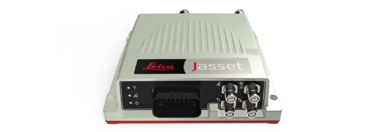
Leica Jasset is a rugged solution used to track mobile or semi-mobile assets. The Leica Jasset
family includes:
Leica Jasset W – Jasset with single Wi-Fi for monitoring semi mobile assets.
Leica Jasset WW – Jasset with dual Wi-Fi for monitoring mobile assets.
Leica Jasset G – Jasset with cellular modem for monitoring semi mobile assets.
Leica Jasset WG – Jasset with single Wi-Fi and Cellular modem for monitoring semi mobile
assets.
Leica Jasset WWG – Jasset with dual Wi-Fi and Cellular modem for monitoring mobile
assets.
System Information 2.1
Caution
This product is intended for Professional Use only.
Note:
The images used in this manual are for reference purposes only; individual screens
and icons may differ from the actual items.
Leica Jasset is a telematics product suited to the tracking of mining assets, including:
Mobile lighting trailers
Communication trailers
Mobile water pumping stations
Moderate size vehicles
Water Pumps
Jasset G, WG, and WWG can also be used as a cellular link for the UHP product (in this
configuration Jasset G, WG, or WWG communicates to the UHP via Ethernet).
Caution:
The SIM card used in Jasset G, WG, and WWG must be a data SIM, and data
must be activated on the carrier’s network. Voice-only networks will not carry
the Jasset data.
Note
Data charges may apply. Due to the activity on the networks, unlimited data contracts
are suggested to avoid extra data charges.
Leica Jasset software provides:
Intuitive set up and operation.
Command line configuration
Upgrade through USB
See Software Installation for more information.
Commercial in Confidence
© Leica Geosystems
3
2.1.1 Jasset W (Single Wi-Fi)
2.1.1.1 Jasset W Components
Jasset W Front View
2.1.1.2 Jasset W Hardware
One L1 GNSS antenna
One Wi-Fi antenna
One Power breakout cable
One power extension cable
Optional: CAN, GPIO, Ethernet breakout cable
Optional: CAN, GPIO extension cable
Optional: CAN, GPIO Ethernet extension cable
Leica Jasset W without Input/Output
Commercial in Confidence
© Leica Geosystems
4
Leica Jasset W with Optional Input/Output
2.1.1.3 Jasset W Features and Specifications
One external Wi-Fi antenna port
One internal Wi-Fi module (2.4 GHz b/g/n 200 mW)
One internal GNSS module (L1 GPS/GLONASS)
One internal 3-axis accelerometer
Two digital inputs
One digital output
Two Serial Ports
Two CAN ports
Industrial metal housing
USB upgrade (back bay)
One Ethernet Port
Ignition controlled available for power saving in vehicles
Commercial in Confidence
© Leica Geosystems
5
2.1.2 Jasset WW (Dual Wi-Fi)
2.1.2.1 Jasset WW Components
Jasset WW Front View
2.1.2.2 Jasset WW Hardware
One L1 GNSS antenna
Two Wi-Fi antennas
One power breakout cable
One power extension cable
Optional: CAN, GPIO, Ethernet breakout cable
Optional: CAN, GPIO extension cable
Optional: CAN, GPIO, Ethernet extension cable
Optional: Mojo screen
Leica Jasset WW Hardware Setup
Commercial in Confidence
© Leica Geosystems
6
2.1.2.3 Jasset WW Features and Specifications
Two external Wi-Fi antenna ports
One internal Wi-Fi module (2.4 GHz b/g/n 200 mW)
One internal GNSS module (L1 GPS/GLONASS)
One internal 3-axis accelerometer
Two digital inputs
One digital output
Two Serial ports
Two CAN ports
Industrial Metal Housing
USB upgrade (back bay)
One Ethernet Port
Ignition control available for power saving in vehicles
Commercial in Confidence
© Leica Geosystems
7
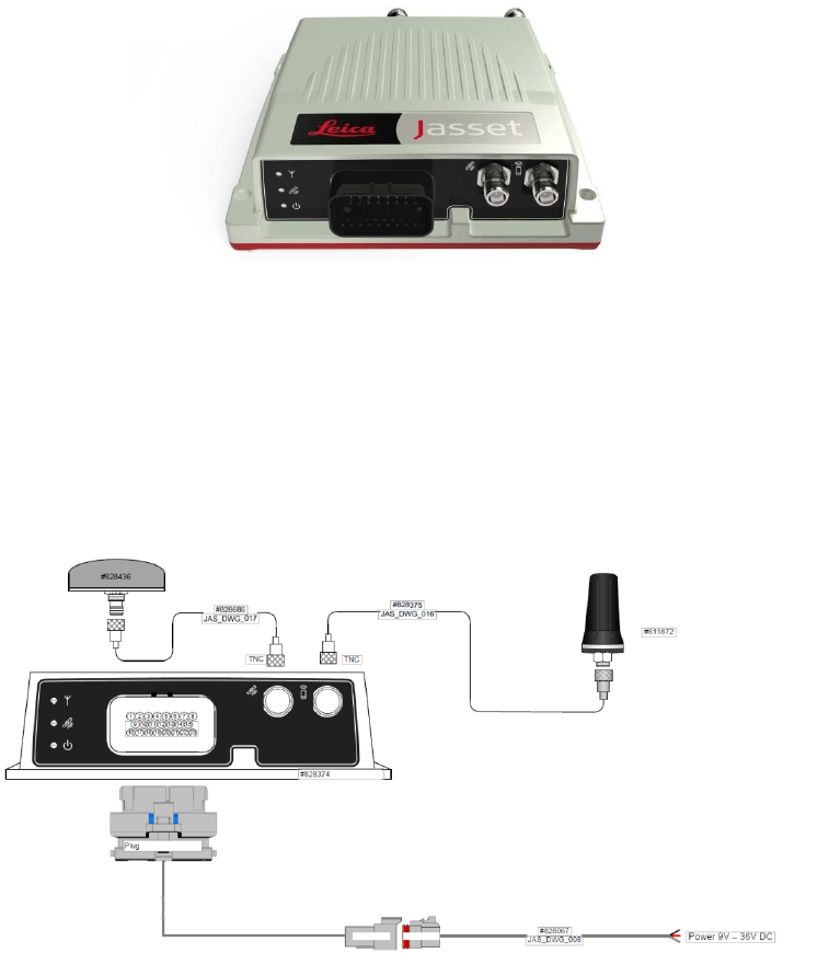
2.1.3 Jasset G (Cellular Communication – No Wi-Fi)
2.1.3.1 Jasset G Components
Jasset G Front View
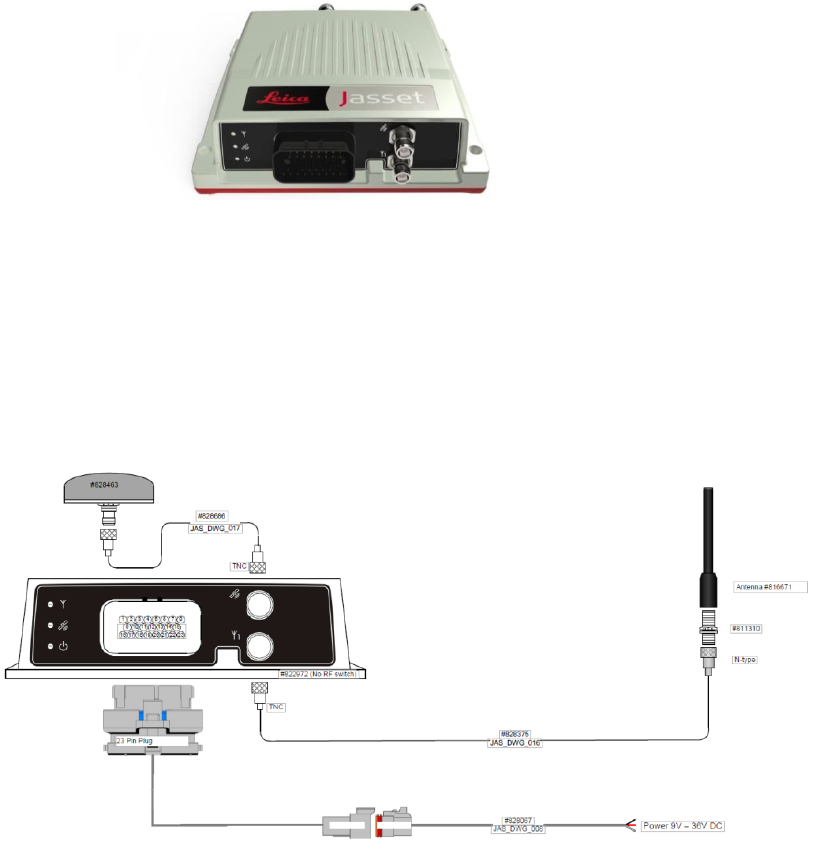
2.1.3.2 Jasset G Hardware
One cellular antenna
One L1 GNSS antenna
One power breakout cable
One power extension cable
Optional: CAN, GPIO, Ethernet breakout cable
Optional: CAN, GPIO extension cable
Optional: CAN, GPIO, Ethernet extension cable
Leica Jasset G without Input/Output
Commercial in Confidence
© Leica Geosystems
8
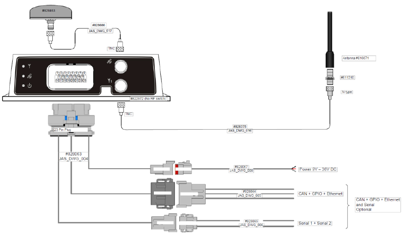
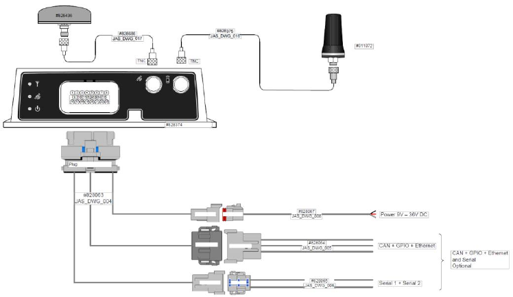
Leica Jasset G with Optional Input/Output
2.1.3.3 Jasset G Features and Specifications
One internal GNSS module (L1 GPS/GLONASS)
One internal 3-axis accelerometer
Two digital inputs
One digital output
Two Serial ports
Two CAN ports
Internal 4G/3G/2G modem
Industrial metal housing
USB upgrade (back bay)
SIM card access (back bay) (SIM card must be a data SIM. Data must be enabled on the
network.)
One Ethernet Port
Ignition controlled available for power saving in vehicles
Commercial in Confidence
© Leica Geosystems
9
2.1.4 Jasset WG (Single Wi-Fi and Cellular Communication)
2.1.4.1 Jasset WG Components
Jasset WG Front View
2.1.4.2 Jasset WG Hardware
One L1 GNSS antenna
One Wi-Fi antenna
One Cellular antenna
One power breakout cable.
One power extension cable
Optional: CAN, GPIO, Ethernet breakout cable
Optional: CAN, GPIO extension cable.
Optional: CAN, GPIO, Ethernet extension cable
Leica Jasset WG without Input/Output
Commercial in Confidence
© Leica Geosystems
10
Leica Jasset WG with Optional Input/Output
2.1.4.3 Jasset WG Features and Specifications
One external Wi-Fi antenna port
One internal Wi-Fi module (2.4 GHz b/g/n 200 mW)
Internal 4G/3G/2G modem
One internal GNSS module (L1 GPS/GLONASS)
One internal 3-axis accelerometer
Two digital inputs
One digital output
Two Serial Ports
Two CAN ports
Industrial metal housing
USB upgrade (back bay)
Ethernet connection to UHP or other products (front AMP connector)
Ignition controlled available for power saving in vehicles
SIM card access (back bay) (SIM card must be a data SIM. Data must be enabled on the
network.)
Commercial in Confidence
© Leica Geosystems
11
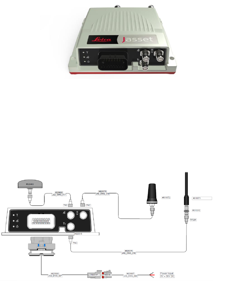
2.1.5 Jasset WWG (Dual Wi-Fi and Cellular Communication)
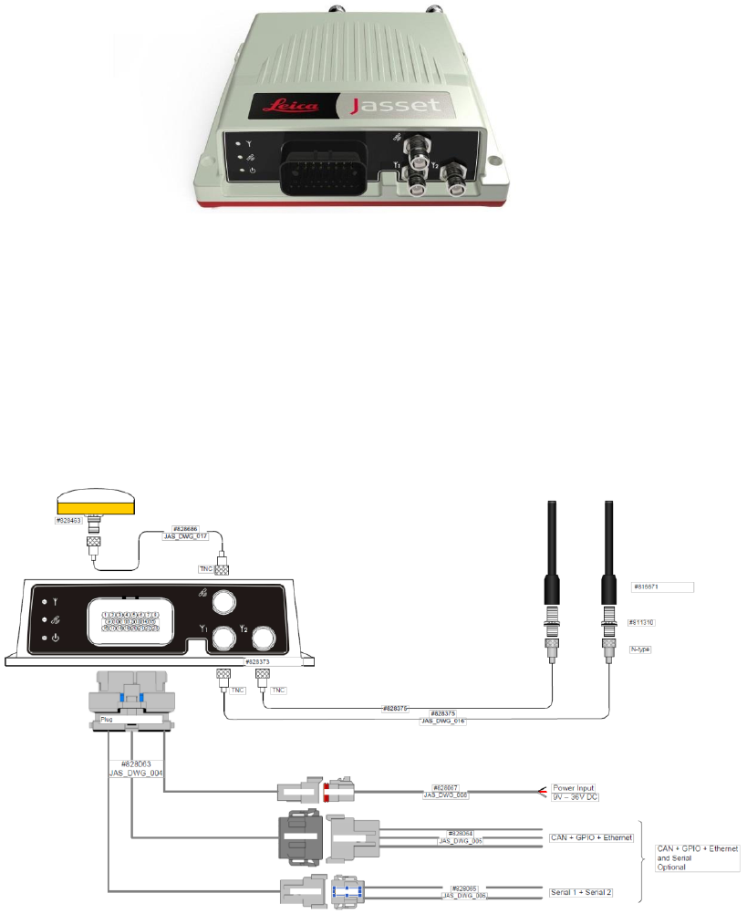
2.1.5.1 Jasset WWG Components
Jasset WWG Front View
2.1.5.2 Jasset WWG Hardware
One L1 GNSS antenna
One Cellular antenna
Two Wi-Fi antennas
One power breakout cable.
One power extension cable
Optional: CAN, GPIO, Ethernet breakout cable
Optional: CAN, GPIO extension cable.
Optional: CAN, GPIO, Ethernet extension cable
Optional Mojo screen
Commercial in Confidence
© Leica Geosystems
12
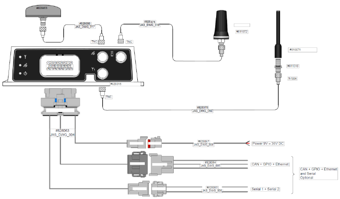
Leica Jasset WWG with Optional Input/Output
2.1.5.3 Jasset WWG Features and Specifications
Two external Wi-Fi antenna ports
One internal Wi-Fi module (2.4G Hz b/g/n 200 mW)
Internal 4G/3G/2G modem
One internal GNSS module (L1 GPS/GLONASS)
One internal 3-axis accelerometer
Two digital inputs
One digital output
Two Serial ports
Two CAN ports
Industrial metal housing
USB upgrade (back bay)
Ethernet connection to UHP or other products (front AMP connector)
Ignition controlled available for power saving in vehicles
SIM card access (back bay) (SIM card must be a data SIM. Data must be enabled on the
network.)
Commercial in Confidence
© Leica Geosystems
13
Product Faceplate Description 2.2
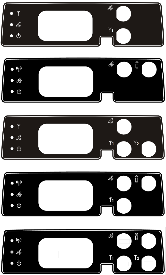
2.2.1 Faceplate Decals
Each variation of the Jasset product has a different faceplate due to functionality available.
Two RF Connector Decal – Jasset W
Two RF Connector Decal – Jasset G
Three RF Connector Decal – Jasset WW
Three RF Connector Decal – Jasset WG
Four RF Connector Decal – Jasset WWG
Commercial in Confidence
© Leica Geosystems
14
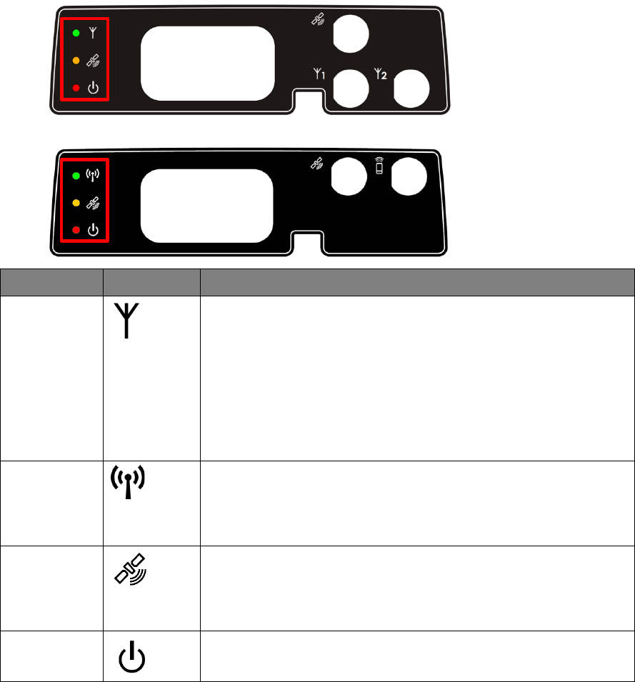
2.2.2 LEDs
All Leica Jasset modules have three LEDs. In normal operation, all three LEDs are on.
Example Jasset LEDs
Example Jasset LEDs
LED
Icon
Function
Green LED
Green LED lights when Leica Jasset W, WW, WG, and WWG are
communicating over a network.
Solid (Wi-Fi connection to or Cellular connection to server)
Flashing (Wi-Fi or Cellular initializing communication)
Note:
For Jasset WW and WWG, with two Wi-Fi antennas
installed, the LED displays the status of the current
signal.
Green LED
Green LED lights when Leica Jasset G, WG, and WWG are
communicating over a network.
Solid (Cellular connection to server)
Flashing (Cellular initializing communication)
Orange LED
Orange LED lights when the Leica Jasset has GPS
communication.
Solid (Differential GPS)
Flashing (autonomous GPS)
Red LED
Red LED lights when the Leica Jasset has power.
Power is on all the time unit is operating.
Commercial in Confidence
© Leica Geosystems
15
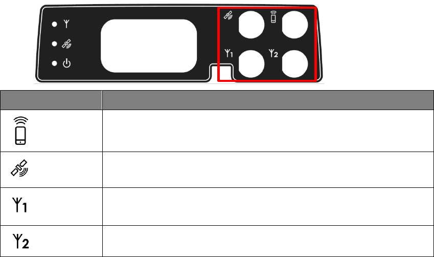
2.2.3 Connector Icons
Each Leica Jasset module has connector function marked on the faceplate.
Example Faceplate with Connector Icons
Symbol
Connector Function
Cellular Modem
GPS Antenna
Wi-Fi 1 Antenna
Wi-Fi 2 Antenna
Commercial in Confidence
© Leica Geosystems
16
Labels 2.3
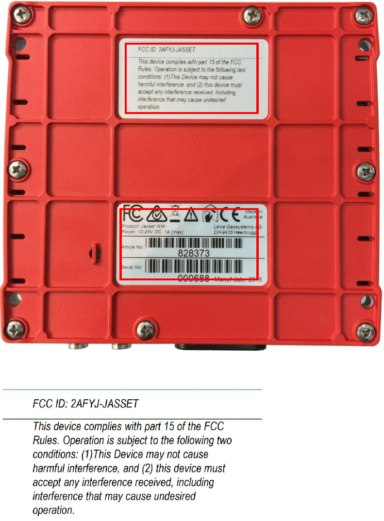
2.3.1 Label Locations
Compliance labels are located on all Jasset modules in the following locations:
FCC Certification Label and Serial Number Label Locations
2.3.2 Jasset FCC Certification Label
FCC Certification Label
Serial Number Label
Commercial in Confidence
© Leica Geosystems
17
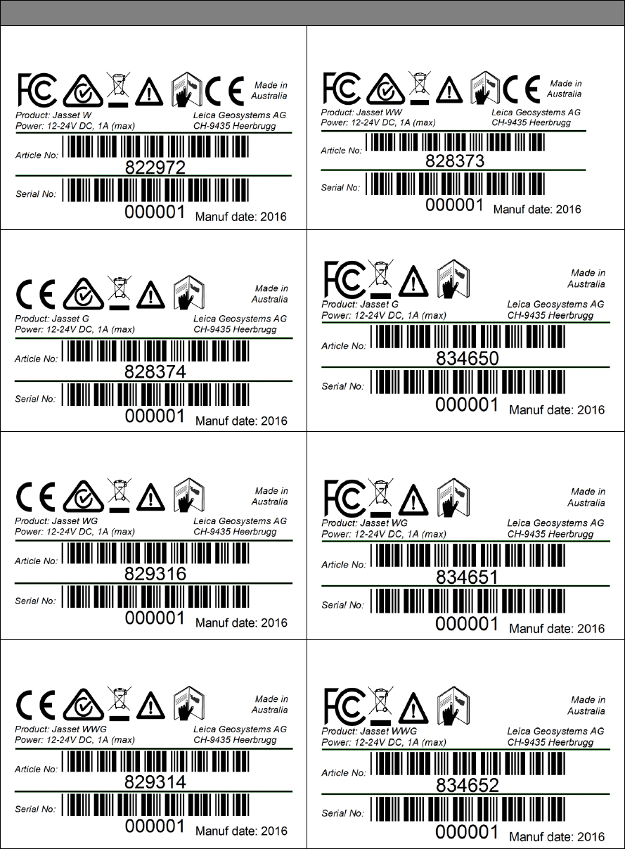
2.3.3 Jasset Serial Number Labels
Jasset Serial Number Labels
Jasset W (Single Wi-Fi) Serial Number Label:
All Markets
Jasset WW (Dual Wi-Fi) Serial Number Label:
All Markets
Jasset G (Cellular) Serial Number Label: All
Markets Outside US
Jasset G (Cellular) Serial Number Label: US
Jasset WG (Single Wi-Fi and Cellular) Serial
Number Label: All markets outside US
Jasset WG (Single Wi-Fi and Cellular) Serial
Number Label: US
Jasset WWG (Dual Wi-Fi and Cellular) Serial
Number Label: All Markets outside US
Jasset WWG (Dual Wi-Fi and Cellular) Serial
Number Label: US

Commercial in Confidence
© Leica Geosystems
18
3 Jasset Commissioning
Commissioning Workflow 3.1
1. See Chapter 4 Hardware Installation.
2. See Section 5.1 Update Leica Jasset Software Using USB Flash Drive.
3. See Section 5.2 Configure Leica Jasset.
4. See Section 5.3 Installations and Configuration Verification.
5. See Section 6.3 Leica Jmineops Equipment Operations.
6. See Section 6.4 Leica Jasset On the Mine Map Application.
Commercial in Confidence
© Leica Geosystems
19
4 Hardware Installation
Before Installation 4.1
Installation requires specialized knowledge and must be installed by a Leica Geosystems Mining
Authorized Installer. Leica Geosystems Mining recommends that installation of the Jasset
equipment be performed by a qualified technician because installation requires making electrical
connections.
Install the system in a clean and dry workshop environment. Failure to do so may cause the
system to short or promote product malfunction.
Route and secure all cables and wiring to ensure that they do not chafe or rub causing
premature failure.
The average installation time varies, but should take approximately one hour per asset. The
time of installation may be more, or less, based on asset type and options purchased.
Jasset Module Installation
4.2
Select an appropriate place to mount the Jasset module.
Four mount holes are provided in the metal housing. These must be used to firmly mount the
module to the asset using the supplied mounts.
4.2.1 Jasset Mounting Accessories
WARNING:
Do not mount the module where it may obscure the driver’s view of the road.
WARNING:
Do not mount the module where it may be struck by a deploying airbag.
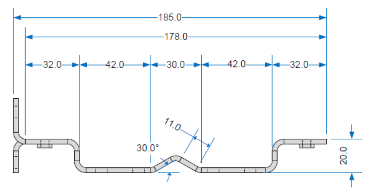
4.2.1.1 Mounting Plates
Mounting Plate Specifications
Commercial in Confidence
© Leica Geosystems
20
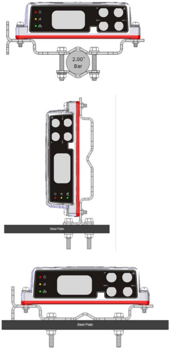
4.2.1.2 Pole Mount
Note:
RF Connectors face downward to help prevent water pooling around the connectors
and possible corrosion.
4.2.1.3 Vertical Mount
4.2.1.4 Flat Mount
Commercial in Confidence
© Leica Geosystems
21
4.2.1.5 Mojo Adapter Plate
An adapter plate is available to install the Jasset module in former Mojo Coms box installations.
4.2.2 Magnetic Mounting
Warning:
Each magnet supplied by Leica has a rated holding force of 40kg. The magnets
have the capability of snapping to any steel structure, trapping any objects,
including fingers, between the steel structure and the magnet face.
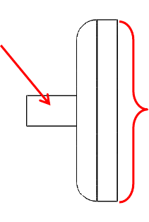
Magnetic mounts are rare-earth magnets attached with a short post to a mounting bracket.
Only the bracket is used when mounting using magnets (similar to the flat or vertical
mounting).
The magnets have an attractive force from the face opposite the mounting stud.
The magnets have strength proportional to the relative thickness of the metal to which they
are attached, meaning the thicker the metal the stronger the magnet’s holding force.
Magnetic Mount
Magnetic mounting
stud
Magnet face –
Attaching face to
asset surface
Commercial in Confidence
© Leica Geosystems
22
4.2.2.1 Magnetic Installation
Caution:
Magnets may cause possible damage to painted surfaces.
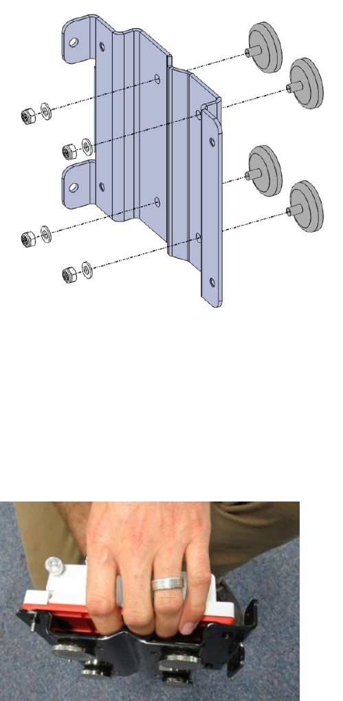
1. Place the bracket and magnets on a workbench or other non-metallic surface.
2. Attach the four (4) magnets using four (4) M6 flat washers and four (4) M6 nyloc nuts to the
bracket assembly as indicated in the illustration.
Bracket Assembly
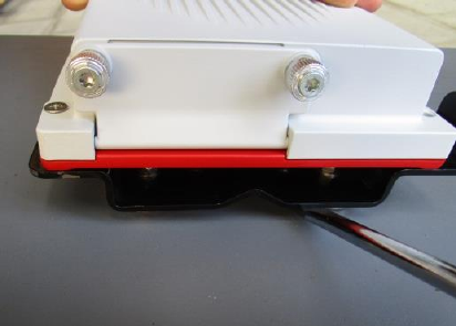
3. Mount the mounting bracket assembly in the agreed upon location.
Warning:
Four magnets have the holding force of 160kg. The bracket has the capability
of snapping to any steel structure, trapping any objects, including fingers,
between the steel structure and the magnet faces.
4. Attach the bracket assembly to the steel structure, gripping the bracket where hands and
fingers are away from potential pinch points. See the illustration for example finger
positioning.
Module Assembly
5. Mount the module to the mounting bracket with the connectors facing down.
6. Ensure adequate space is allowed for connecting external cables to the module.
Commercial in Confidence
© Leica Geosystems
23
4.2.2.2 Magnetic Mount Removal
Warning:
Four magnets have the holding force of 160kg. The bracket has the capability
of snapping to any steel structure, trapping any objects, including fingers,
between the steel structure and the magnet faces.
Removal of assembly is done by carefully prying the bracket, with the Jasset module still
attached, from the steel structure using a large flat bladed screwdriver.
1. Wedge the screwdriver under one magnet post and lift the entire bracket module assembly
and remove.
Remove Magnetic Mount
2. Remove the magnetic mount.
Power Cable Installation 4.3
CAUTION:
The Jasset module is a 12 or 24-volt DC (negative-to-earth) system only.
Connecting to a positive-to-earth system will cause damage which is not
covered by warranty.
1. Connect the supplied power cable to a reliable power source, for example, the vehicle’s main
power system.
a. Connect the unit to a 12 or 24-volt positive source capable of delivering a constant
3 A.
b. Connect the black wire to the vehicle’s earth ground.
2. Route and secure all cables and wiring to ensure that there is no rubbing, which can cause
premature failure.
3. Connect the power cable to the power connector on the front of the module.

Commercial in Confidence
© Leica Geosystems
24
Antenna Installations 4.4
4.4.1 Antenna Application
To ensure correct antenna application for mobile or fixed assets, refer to the Antenna Application
table.
Warning
Only antenna listed in the Antenna Application table are permitted to be used.
The Jasset Wi-Fi and Cellular antennas must be mounted more than 30cm away
from the operator.
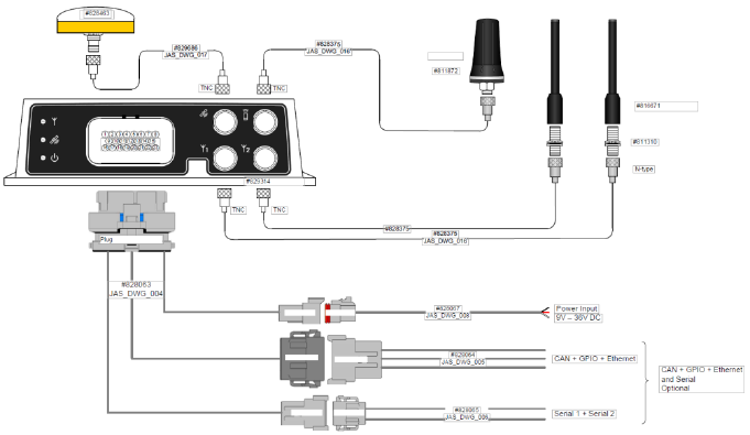
Only antenna cables provided with the Jasset equipment for installation as
identified in Jasset installation diagrams in section 2.1 for the appropriate Jasset
variant are to be used in Jasset antenna installations.
Antenna Application
Asset Type
Required Antenna : Leica Part Number
Semi Mobile Asset:
Portable Toilet
Communications Wi-Fi Trailer
Generator
Water Pumps
Mobile Lighting Trailers
GNSS: 828463
Wi-Fi: 816671
3G Cellular: 811872
Mobile Asset:
Light mining vehicles
GNSS: 828463
Wi-Fi: 816671
3G Cellular: 811872
4.4.2 GNSS Antenna Installation
Note:
Read all instructions prior to assembly and installation.
The Jasset module’s GNSS Antenna must be mounted with a clear view of the sky and free from
any obstruction from machine components, and must meet the following criteria:
1. The Jasset module GNSS Antenna must be on the flat level part of the machine or mast.
2. The Jasset module GNSS Antenna must not be obstructed by exhausts, flashing lights,
masts, trays, or any other objects. It must be mounted such that it has an unobstructed view
of the sky and is as high on the equipment as possible.
3. The Jasset module GNSS Antenna must not be mounted within 20 cm of any other antenna.
4. Route the cables through bulkheads using the existing grommets if possible; if not,
modification may be required to route the cables to the required location. If creating a new
entry point, use a grommet to protect the cables.
5. The cables must not be cut, kinked, or bent tightly, as their performance degrades and a
system failure may result.
6. Route the cables back to the Jasset module.
7. If cables are not terminated, terminate the cable and check connectivity before connecting to
the antenna
8. A universal antenna mounting bracket is supplied to secure the GPS antenna.
9. Mount the GNSS Antennas through the 18 mm holes in the universal antenna bracket and
secure the antennas using a lock nut.
Commercial in Confidence
© Leica Geosystems
25
10. Mount the universal bracket onto the equipment location using the bolts provided.
11. Connect the TNC cable connector to the antenna and route the cable to the Jasset module
and connect TNC to the Jasset GPS port.
4.4.3 Wi-Fi Antenna Installation
For the Jasset module communication is transmitted using Wi-Fi. The Wi-Fi antennas and cabling
are installed using the following hardware:
Warning:
Antennas must be mounted more than 30 cm away from the human body.
Caution:
Antennas must be mounted more than 20 cm away from any other antenna.
Note:
Wi-Fi connectivity is dependent on network infrastructure which is outside the scope
of this manual.
1. One or two 2.4 GHz antennas are used depending on version requirements.
2. Route the cables through existing grommets if possible; if not, modification may be required to
route the cables to the required location. If creating a new entry point, use a grommet to
protect the cables.
3. The cables must not be cut, kinked, or bent tightly, as their performance degrades and a
system failure may result.
4. Route the cables back to the Jasset module.
5. If cables are not terminated, terminate the cable and check connectivity before connecting to
the antenna
6. Wi-Fi antenna must be installed at a fixed offset of multiple 2.4 GHz wavelengths for reasons
of diversity.
7. A universal antenna mounting bracket is supplied to secure the Wi-Fi antenna.
8. Mount the N-type adapter through the 16 mm hole in the universal bracket and secure the
antenna using a lock nut.
9. Mount the Wi-Fi antenna to the N-type adapter.
10. Mount the universal antenna bracket onto the equipment in a location more than 30 cm away
from the human body and more than 20 cm from other aerials and equipment structure.
11. Secure universal mounting bracket to the equipment using the provided bolts.
12. Connect the N-male connector to N-type adapter and route the cable to the Jasset module
and connect the TNC connector to the Wi-Fi port.
Commercial in Confidence
© Leica Geosystems
26
4.4.4 Cellular Antenna Installation
Warning:
Antennas must be mounted more than 30 cm away from the human body.
Caution:
Antennas must be mounted more than 20 cm away from any other antenna.
Caution:
The SIM card used in Jasset G must be a data SIM, and data must be activated
on the network. Voice-only networks will not carry the Jasset data.
Note:
Cellular data connectivity is dependent on network infrastructure which is outside the
scope of this manual.
For the Jasset module (G, WG, WWG) communication is transmitted using cellular data networks.
The cellular antenna and cabling is installed using the following hardware:
1. One Cellular antenna is used.
2. Route the cable through the existing grommets if possible; if not, modification may be
required to route the cables to the required location. If creating a new entry point, use a
grommet to protect the cables.
3. The cable must not be cut, kinked, or bent tightly, as their performance degrades and a
system failure may result
4. If cables are not terminated, terminate the cable and check connectivity before connecting to
the antenna
5. Route the cable back to the Jasset module.
6. A universal antenna mounting bracket is supplied to secure the Cellular antenna.
7. Mount the N-type adapter through the 16 mm hole in the universal bracket and secure the
antenna using a lock nut.
8. Mount the 4G antenna to the N-type adapter.
9. Mount the universal antenna bracket onto the equipment in a location more than 30 cm away
from the human body and more than 20 cm from other aerials and equipment structure.
10. Secure universal mounting bracket to the equipment using the provided bolts.
11. Connect the N-male connector to N-type adapter and route the cable to the Jasset module
and connect the TNC connector to the 4G port.
SIM Card Installation – Jasset G, WG, and WWG 4.5
Caution:
The SIM card used in Jasset G, WG, and WWG must be a data SIM, and data
must be activated on the network. Voice-only networks will not carry the Jasset
data.
Note
Data charges may apply. Due to the activity on the networks, unlimited data contracts
are suggested to avoid extra data charges.
To enable cellular support on systems equipped with a 2/3/4G internal modem a data SIM card
from a suitable service provider is required
1. Place the unit on a workbench.
2. Unscrew the two captive thumb screws by hand and open the cover for the SIM card slot.
3. Use a pointed instrument to press the release mechanism.
4. Slide out the SIM card holder.
5. Place data SIM card into SIM card holder with the chip facing up.
Commercial in Confidence
© Leica Geosystems
27
Note:
Ensure that the SIM card is securely seated in the holder.
6. Insert the SIM card holder back into the SIM card slot.
CAUTION:
Ensure that the black rubber seal is fitted correctly into the groove in the
access panel door to keep water and dust out to prevent damage to the internal
circuitry.
7. Replace the cover, and replace screws to secure.
8. When the unit is turned on, ensure the wireless connection LED appears.
Commercial in Confidence
© Leica Geosystems
28
5 Software Installation
Leica Jasset is provided with a low level configuration before it is shipped from Leica Geosystems
Mining. Each unit requires a site-specific software update on site. The following procedure is also
used for software upgrades.
Note:
Contact Support for the required files.
Update Leica Jasset Software using USB Flash Drive 5.1
CAUTION
Do not turn off the unit, or remove the USB Flash Drive (key) while the software
upgrade is under way.
The software is installed from a USB Flash Drive (key). Installation files are provided by Leica
Geosystems Mining support and are specific for each installation site.
Procedure Requirements:
A Computer connected to the mine Ethernet
Clean USB key.
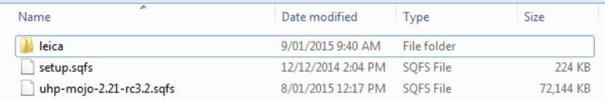
1. Using the computer, extract the provided files and copy onto the clean USB key:
leica\autorun
uhp-mojo-?.sqfs
2. Copy the site setup.sqfs to the USB key (this is the same setup.sqfs as used on the site’s
other Jigsaw USB flash keys).
setup.sqfs
3. The files on the USB key appear as in the graphic:
4. To start the unit, connect the service cable to the Leica Jasset and supply power.
5. Configure the computer’s local ethernet to a static IP address of 192.168.200.10 and a
netmask of 255.255.255.0 and connect to the Jasset using the Ethernet extension cable.
6. Unfasten two captive thumb screws and open the USB port access panel.
7. If the Jasset module is powered off, power on the unit.
8. After approximately 30 seconds ping the unit on the address 192.168.200.1 continually until
there is a response.
9. Open up the web browser and enter the following http://192.168.200.1/platform-setup to verify
the unit has completed its start-up sequence and it is safe to plug in the USB key.
CAUTION
Do not turn off the unit, or remove the USB Flash Drive (key) while the software
upgrade is under way.
10. Insert the USB key into Leica Jasset module USB port after the unit has powered on.
Note:
LED status prior to the software update may vary.
The format process can take between three to five minutes to complete, once the
process is complete all three LEDs on the Leica Jasset start to flash for
approximately 10 seconds and then remain on permanently.

Commercial in Confidence
© Leica Geosystems
29
11. In updating the unit, whether the module is configured or not configured, any installed
software is overwritten and an update is forced.
12. During the software upgrade the following is observed:
a. At the beginning of the upgrade all LEDs are momentarily off. The red power LED
then flashes on and off three times.
b. All LEDs are on permanently while the firmware upgrade progresses.
c. The process completes when all three LEDs on the Leica Jasset start to flash on and
off indefinitely, indicating the upgrade is complete and that the Jasset module is in an
unconfigured state.
13. When the process is complete, remove the USB key from the unit and start the configuration
process. See Configure Leica Jasset.
CAUTION
Ensure that the black rubber seal is fitted correctly into the groove in the
access panel door to keep water and dust out to prevent damage to the internal
circuitry.
14. Close the USB access panel and fasten the thumb screws hand tight. Ensure the access
panel is secured to retain the weather-resistance rating of the Jasset module.
Configure Leica Jasset 5.2
CAUTION
Ensure the USB key is removed before performing configuration.
1. Make sure the software is upgraded and the USB key removed before performing this
procedure.
Note:
One or two cables are required for the technician to connect a computer over
ethernet to the Jasset.
Part No 828063, Drawing number JAS_DWG_004, Jasset Breakout cable
Part No 832053, Drawing number JAS_DWG_020, Jasset Ethernet Extension
RJ45 cable
2. Connect the service cable to the Leica Jasset and supply power so that the unit is operating.
3. Once Jasset has booted up and is operating, configure the computer’s local ethernet to a
static IP address of 192.168.200.10 and netmask of 255.255.255.0
4. Ping 192.168.200.40 (Jasset’s local Ethernet IP address) before proceeding.
Commercial in Confidence
© Leica Geosystems
30
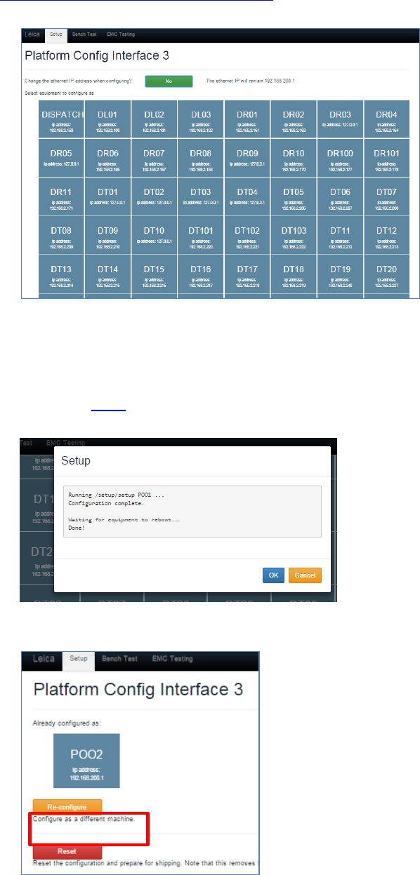
5. Open a web browser and enter the following:
http://192.168.200.40/platform-setup
The following dialog appears:
6. The system prompts to change the ethernet IP address when configuring. The ethernet
address is set to the default 192.168.200.1.
7. Select No to keep the default ethernet IP address.
8. Select the equipment to configure the unit. The unit reboots and starts to operate within two
minutes. See LEDs for information on LED status indication.
9. Web Windows shows a Done status after loading when reboot is complete.
10. The unit can be reconfigured as a different unit by accessing the web interface and selecting
the reconfigure button to select different equipment as shown.

Commercial in Confidence
© Leica Geosystems
31
Installation and Configuration Verification 5.3
1. Ensure the unit is powered as indicated by the Jasset LED status for power.
2. Ensure the GPS and Wi-Fi is correct. Refer to Section 2.2.2.
3. Use Jmineops Equipment Operations to verify Jmineops server can see the Jasset module.
See Leica Jmineops Equipment Operations on page 37.
4. Use Jmineops Mine Map to verify the Jasset is present in the expected location on the Mine
Map. See Find a Jasset on the Jmineops Mine Map on page 39.
Commercial in Confidence
© Leica Geosystems
32
6 Leica Jmineops Jasset Office Administration
The Leica Jasset product is administered using the Leica Jmineops application. These
procedures cover only Leica Jasset-specific Leica Jmineops functionality. For regular Leica
Jmineops processes please see the Jmineops documentation.
Note:
To interact with Jmineops, the Jasset must be configured in the Jmineops system.
Asset Icon 6.1
The asset icon represents the equipment and the equipment position in relation to the Mine Map
and other equipment on the Mine Map both in Jmineops and on the Jpanel.
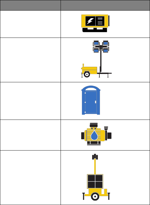
6.1.1 Available Asset Icons
Note:
Asset icons are based on specific asset types. The icons shown may differ from the
icons on the screen. If other asset icons are required, contact Leica Geosystems
Mining support.
Asset Icons
Asset Type
Appearance
Generator
Lighting Plant
Portable Toilet
Pump
Communications Wi-
Fi Trailer
6.1.2 Asset Proximity Ring
The proximity radius ring displays on the Jpanel GPS tab to allow equipment users to see the
acceptable proximity to an asset. The radius ring’s night and day color, thickness, and radius are
configured. If changes are required, please contact Leica Geosystems Mining support. The asset
proximity ring is shown in all field device Jpanels and is for visual indication only.
Commercial in Confidence
© Leica Geosystems
33
6.1.3 Leica Jasset Representation on the Mine Map
Assets are displayed with the Asset Name and Asset Icon on the mine map.
Example Asset with Asset Name
Asset
Asset with Proximity Ring
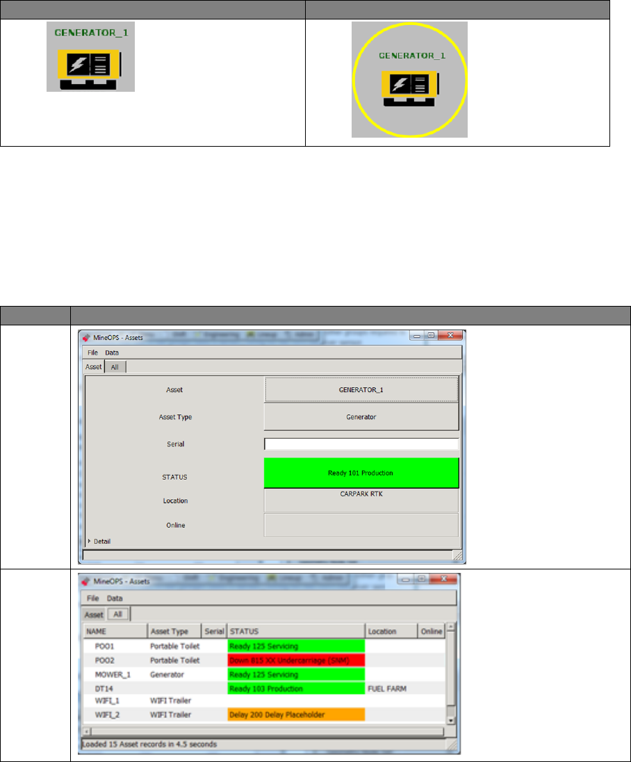
Jmineops Asset View 6.2
The Asset view allows the user to view and edit information for configured assets in the Jmineops
system. The Assets view is accessible from the Mine Map or from the Assets menu item.
The Jmineops Asset view has two tabs:
Asset: details a single asset.
All: details all assets in the system.
Asset View Tabs
Tab
View
Asset
All
Commercial in Confidence
© Leica Geosystems
34
Asset information displayed in the view includes:
Field
Description
Asset, Name
Name of the asset.
Asset Type
Type of asset. Asset types must be configured.
Serial
Serial number of the asset selected.
Status
The asset’s current status and reason. For more information on Status
and Reason setting, see Change Status and Activity.
Location
The current location of the asset.
Buttons, tabs, and commands available in this view are:
Field
Display
Description
FILE
The configurable menu usually provides
Save As, Print PDF, and Close options.
Data
The configurable menu usually provides
data handling options e.g. Refresh and Filter
options.
Asset
Asset tab allows the viewing of details of a
single asset from a list.
All
All tab allows the viewing of a detail list of all
assets in the system.
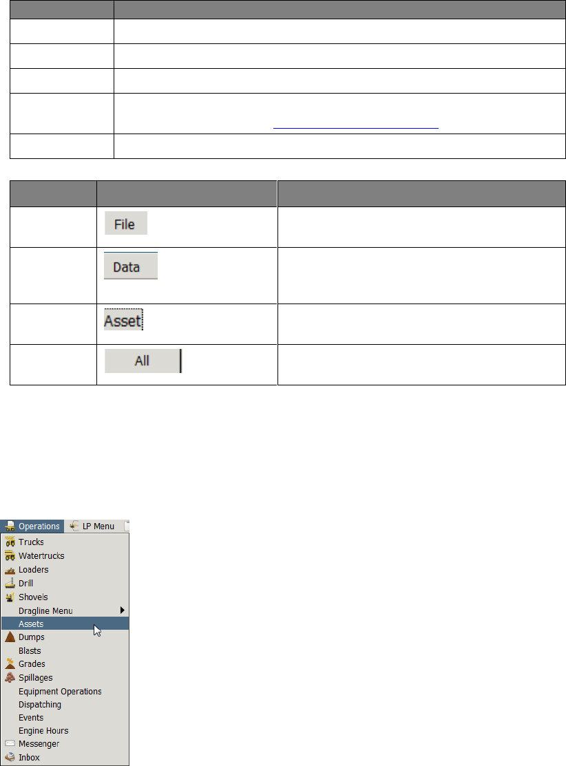
6.2.1 Access Asset View from Jmineops
An asset’s attributes can be changed using Leica Jmineops Asset view.
Note:
Leica Jmineops menus are configurable; the Asset menu item location may vary.
1. To access the Asset view, select Operations > Assets.
The Asset view appears.
Commercial in Confidence
© Leica Geosystems
35
2. To display all assets on the mine site, select All.
6.2.2 Change an Asset’s Attributes
Assets have direct attributes (e.g. status) that are accessible only through the asset object and
indirect attributes (e.g. length) inherited from the underlying equipment object.
To update:
Direct attributes, use the Asset view (particular fields are shown in following sections).
Equipment length etc, see Update an Asset’s Equipment Attributes on page 42.
Location, but only for a stationary asset, see Change Position of a Stationary Asset on Mine
Map on page 43.
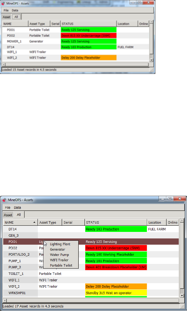
6.2.2.1 Change Asset Type
To change the asset type:
1. Select Operations > Assets, select All. The Assets view appears.
2. Select the row of the asset. The asset’s row is highlighted.
3. Select the Asset Type field of the asset’s row. A drop-down menu of asset types appears.
4. Select the required asset type. The asset type is applied to the asset.
Commercial in Confidence
© Leica Geosystems
36
6.2.3 Change Status and Activity
Note
Status and activities changes can be automated if Jasset is connected to a switch or
a PLC. Contact Leica Geosystems Mining support for more information.
Use the STATUS option to change the equipment status to match the current activity. At each
status change, the Mine Controller is notified and the status changes are recorded throughout the
day which assists in the monitoring of mine scheduling. When the system is running, the
equipment is always in a status state. Follow the mine site’s requirements for changing equipment
status.
Note
The status options in the system may vary from those presented in this manual.
Status options are configured in accordance with equipment and mine site
requirements.
Status options are
Ready—the asset is ready for work.
Delay—the asset is delayed.
Down—the asset is unavailable for work.
Standby—the asset is waiting.
After selecting the equipment status, select a reason or state for that status. Each status has a
menu of reasons (or states) that are configured for each mine site.
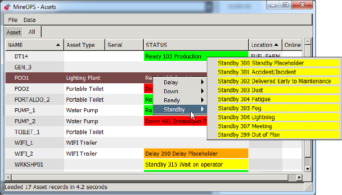
To set the asset’s status:
1. Select Operations > Assets. The Assets view appears. Select All.
2. Select the row of the asset. The asset’s row is highlighted.
3. Select the STATUS field of the asset’s row. A drop-down menu of statuses appears.
4. Select the required status. A drop-down menu of reasons appears.
5. Select the required reason. The status and reason is applied to the asset.
Commercial in Confidence
© Leica Geosystems
37
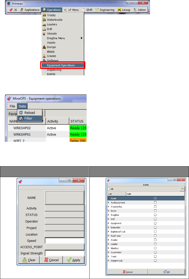
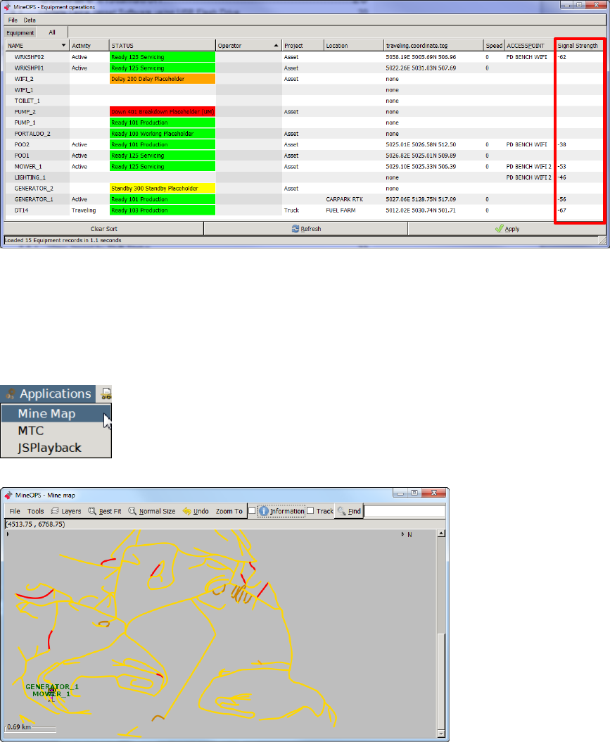
Leica Jmineops Equipment Operations 6.3
The Leica Jmineops Equipment Operations view provides a similar view to Asset view, but
provides Wi-Fi and GPS connectivity information, which can be used to validate communications
between the asset and the Jmineops server, and verify the Asset GPS is working.
1. To open the Equipment Operations view, select Operations > Equipment Operations as
shown.
The Equipment Operations view appears.
2. Select Data > Filter from the Equipment Operations menu.
The equipment operations filter dialog box appears.
3. Select the NAME button. The NAME menu options appear. Select the Asset check box and
then select OK to display assets only.
Name Button
Asset Box
4. Select the Apply button to show the filtered (i.e. Asset) item.
Commercial in Confidence
© Leica Geosystems
38
5. To verify the Wi-Fi communications between the Jmineops server and the Jasset module is
working, check the value in the signal strength column. The received signal strength
indication (RSSI) range is -93 for OK to -53 for Excellent. If the value is outside that range,
signal strength is marginal to poor.
Leica Jasset on the Mine Map Application 6.4
The Leica Jmineops Mine Map can be configured with a Jasset layer. Any Jasset configured in
Leica Jmineops can be displayed on the Mine Map Jasset layer.
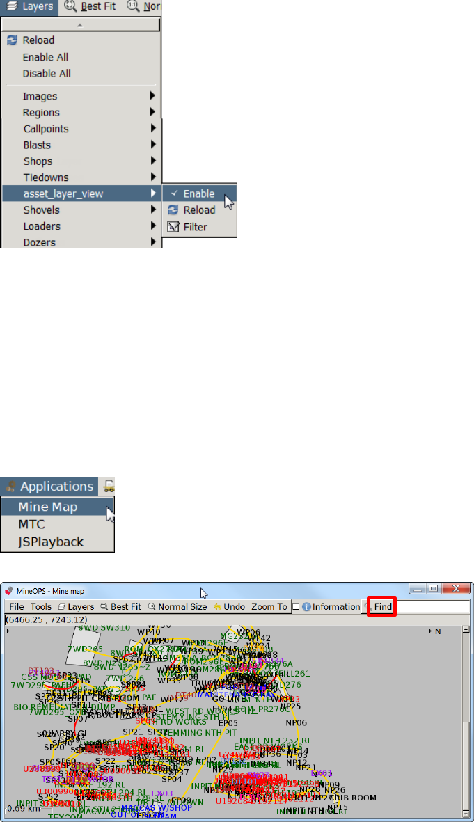
6.4.1 Enable Jasset Layer on Mine Map
1. To access the Mine Map, open Jmineops, select Applications > Mine Map, the Mine Map
view appears.
2. If the Asset layer is enabled, Jassets are displayed by asset name and asset icon.
Commercial in Confidence
© Leica Geosystems
39
3. To enable the Asset layer, select Layers > Asset > Enable.
Note:
The Jasset Layer menu options are:
Enable—Enables the Jasset layer which displays the assets in their last known
location.
Reload—Reloads available Jassets on the Mine Map.
Filter—Filters Jassets by selected criteria.
6.4.2 Find a Jasset on the Jmineops Mine Map
When the Jasset layer is enabled, Jassets can be found on the Mine Map.
1. To access the Mine Map in Leica Jmineops, select Applications > Mine Map, the Mine Map
view appears.
2. Select the Mine Map Find button, a menu of all items on the map appears.
Commercial in Confidence
© Leica Geosystems
40
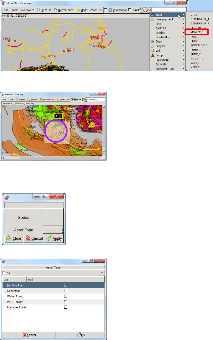
3. Select Asset, a menu of configured assets appears. Select the required asset.
4. The callout and asset proximity radius flashes on the Mine Map display. Hover the cursor over
the flashing callout and the asset is circled on the map.
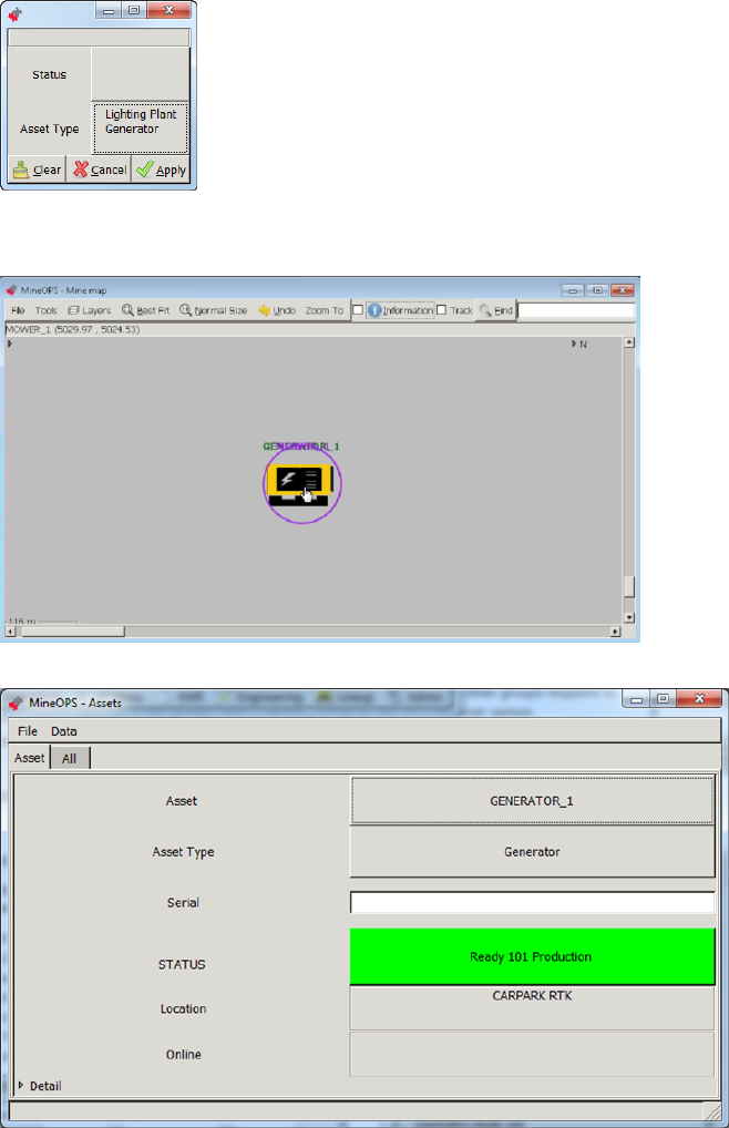
6.4.3 Filter Assets on Mine Map by Asset Type
1. To filter assets on the Mine Map by activity, select Layers > Asset > Filter. The filter option
dialog box appears.
2. Select Asset Type. The Asset Type dialog box appears.
Note:
More than one asset type may be selected. Selecting a specific asset displays only
the assets which are available on the Mine Map. If no asset type is selected, all
assets are displayed.
Commercial in Confidence
© Leica Geosystems
41
3. Select the check box for the asset types to display, select OK.
4. The Filter Option dialog box appears with the Asset Type populated with the asset types
selected. Select Apply. The Mine Map displays only the assets of the selected type.
6.4.4 Access Jmineops Asset View from Mine Map
1. To access the Asset view from the Mine Map, locate the asset on the mine map.
2. Double-click on the asset. The Asset view appears with the asset’s details.
Commercial in Confidence
© Leica Geosystems
42
6.5 Update an Asset’s Equipment Attributes
CAUTION
Do not change an asset equipment’s NAME or create a non-stationary asset:
these actions can make the specified asset unmanageable.
To update an asset’s equipment attributes:
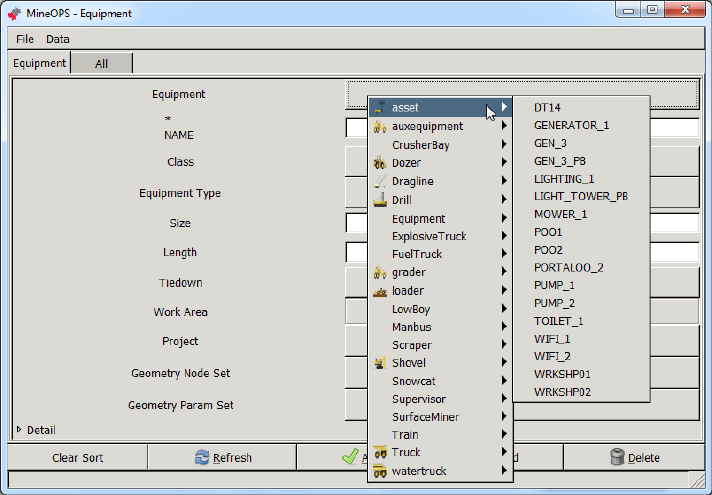
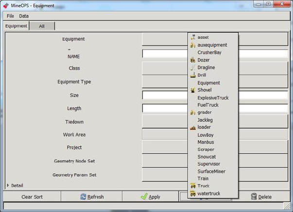
1. Select Engineering > Equipment. The Equipment view appears.
2. Select the Equipment tab.
3. Select the Equipment field. A drop-down menu of equipment types appears. Select asset. A
drop-down menu of assets appears.
4. Select the required asset.
5. Update fields.
Note
Set the Length field because that value is used to scale the asset’s icon on the Mine
Map. A recommended minimum value is 10.
The Geometry Node Set and Geometry Param Set fields are not applicable.
Enter values for the fields as required.
6. Select the Apply button. The attributes are applied.
Create and Maintain a Stationary Asset 6.6
CAUTION
Do not create an asset other than a stationary asset: non-stationary assets
require additional configuration to make them operational.
Use a stationary asset to track an asset that must appear on the Mine Map but that never moves
and therefore doesn’t need an attached GNSS locator.
Use the following procedures to create a stationary asset and to set the asset’s position. To set
the asset’s status etc see Change an Asset’s Attributes on page 35.
Commercial in Confidence
© Leica Geosystems
43
6.6.1 Create a Stationary Asset
To create a stationary asset:
1. Select Engineering > Equipment. The Equipment view appears.
2. Select the Equipment tab.
3. Select Add. The Equipment Class drop-down menu appears.
Select asset. The Equipment field is auto-populated with a name and the Class is set.
4. Select the NAME field, enter the asset’s unique name.
Note
Set the Length field because that value is used to scale the asset’s icon on the Mine
Map. A recommended minimum value is 10.
5. Enter the Length field.
Note
The Geometry Node Set and Geometry Param Set fields are not applicable.
6. If required, enter values for the remaining fields.
7. Select the Apply button. The asset equipment is created.
8. Set the asset’s position—see Change Position of a Stationary Asset on Mine Map below.
9. Set the asset’s attributes, especially asset type and status—see Change an Asset’s Attributes
on page 35.
6.6.2 Change Position of a Stationary Asset on Mine Map
Use this procedure if an asset location is incorrect, or requires adjustment from the office.
Note:
This procedure only applies to stationary assets
1. Select Engineering > Equipment Positioning. The Equipment Positioning view appears.
2. Select Equipment.
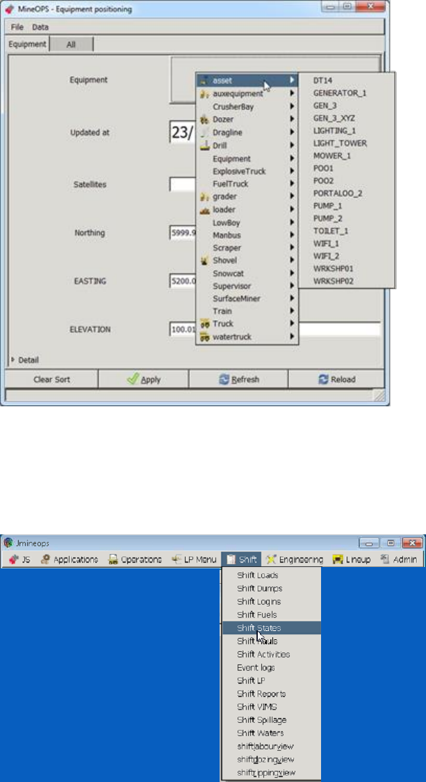
Commercial in Confidence
© Leica Geosystems
44
3. Select the Equipment field. A drop-down menu of equipment classes appears. Select asset.
A drop-down menu of assets appears.
4. Select the required asset.
5. Edit the location fields.
6. Select Apply.
View Jasset using Shift State View 6.7
1. Select Shift > Shift States, the shift States view appears.
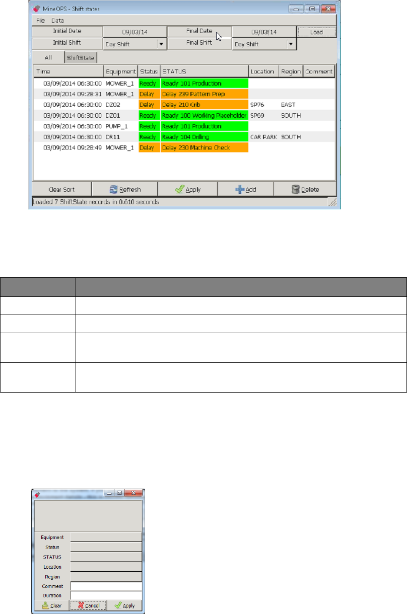
Commercial in Confidence
© Leica Geosystems
45
2. Select the Initial Date, Initial Shift, Final Date, and Final Shift. Select Load.
Note:
Asset Status can be changed in the Shift State view.
3. The shift states view is populated with the asset status during the selected shifts.
Information displayed in the view includes:
Field
Description
Time
Time that the state record was created.
Equipment
Equipment name—same as the asset name.
Status
The equipment’s status. Status values are configurable but typically
include Ready, Delay, Down, Standby.
STATUS
The equipment’s status and reason. Status and reason values are
configurable.
6.7.1 View Jasset by Shift Status
Assets may be filtered by status (e.g. Ready) or by status and activity (e.g. Standby -
Accident/Incident).
To filter assets on the Shift States view by status or status and activity:
1. Select Data > Filter. The filter option dialog box appears.
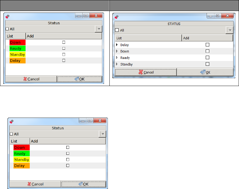
Commercial in Confidence
© Leica Geosystems
46
2. To filter by status, select Status. To filter by status and activity, select STATUS. The relevant
dialog box appears.
Status Dialog Box
STATUS Dialog Box
To filter by status only:
1. Select Data > Filter > Status. The Status dialog box appears.
Note:
More than one status may be selected.
2. Select the check box for the status to display, select OK. The filter option dialog box appears
with the Status field set to the selected value(s).
3. Select Apply. The assets with the selected status are displayed in the Shift States view.
Note:
Selecting a specific status displays only the assets that have the selected status. If
no status is selected, all assets of any status are displayed.
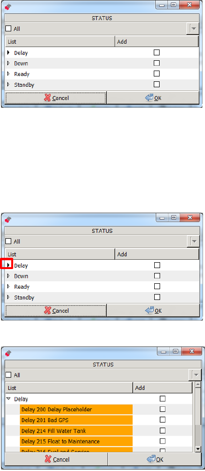
Commercial in Confidence
© Leica Geosystems
47
To filter by status and reason:
1. Select Data > Filter > STATUS. The STATUS dialog box appears.
Note
More than one status may be selected.
All reasons or individual reasons for a status may be selected.
2. To select all reasons for a status, select the check box for the status.
3. To select a specific status and reason:
a. Select the drop-down button beside the status.
The drop-down menu displays the reasons assigned to the status.
b. Select the check box for a reason to display.
4. Select OK. The filter option dialog box appears with the STATUS field set to the selected
value(s).
5. Select Apply. The assets with the selected status and reason are displayed in the Shift
States view.
Note
Selecting a specific status and reason displays only the assets which have the
selected status and reason. If no status and reason is selected, all assets of any
status/reason are displayed.
Commercial in Confidence
© Leica Geosystems
48
Set Update Timing (Low Power Mode) 6.8
If the Jasset is running on battery power it can operate in low power mode. In the low power
mode, the Jasset module is configured to shut down and to operate at timed intervals. Jmineops
is configured to update during these time intervals to conserve battery power.
The wakeup timeout is calculated using the system up time and not the clock.
The default wakeup interval is 3600 seconds (60 minutes). This means the unit starts up at
approximately the same time each hour.
The default timeout is 900 seconds (15 minutes), giving the unit a maximum of 45 minutes in
every hour spent off. If the system can connect and complete a replication cycle in less than
15 minutes, the unit spends more time asleep.
In low power mode, battery power can last up to ten days.
To change Jmineops update timing, please contact Leica Geosystems Mining support.
6.9 Manage Engine Hours
The Jasset product can track engine (operational) hours. Available tracking methods are manual
input and switch sensor input.
To enable the engine hours option, please contact Leica Geosystems Mining support.
Monitor Asset Overspeed Alerts 6.10
Overspeed alerts on mobile assets are monitored in the same manner as other alerts in the
Jmineops system. To configure over speed alerts, please contact Leica Geosystems Mining
support.
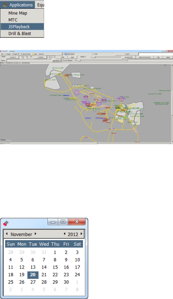
Commercial in Confidence
© Leica Geosystems
49
Jasset on Jsplayback 6.11
The historic location of the Jasset can be tracked on Jsplayback.
Note:
Ensure the Jasset layer is enabled in the Jsplayback application. If the Jasset layer is
not enabled on Jsplayback, contact Leica Geosystems Mining support.
1. Select Applications > JSPlayback.
2. The mine map appears with roads and the asset icons visible.
3. If asset icons are not visible, to show assets on the view, select Layers > Asset > enable.
4. Set the date range for playback.
a. Select the From Date button, the date calendar appears, Double click the date to
select.
b. Select the From Hour, Minute, Second as required.
c. Select the To Date button, the date calendar appears. Double click the date to select.
d. Select the To Hour, Minute, Second as required.
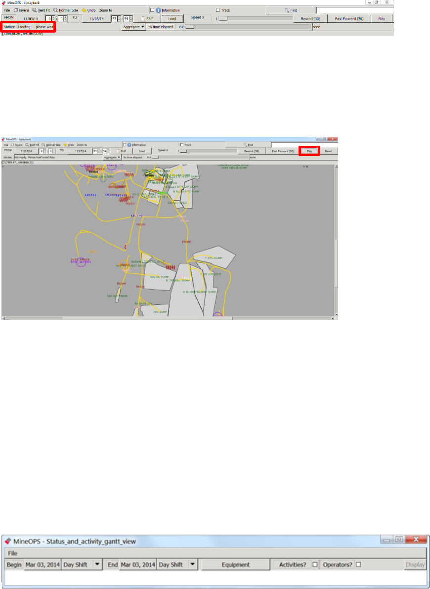
Commercial in Confidence
© Leica Geosystems
50
5. Select Load. The data loads.
Note
Loading data for Jsplayback may take time depending on the length of the date range
selected. The system displays Processing GPS Data in the status bar while the data
loads.
6. The status bar displays Press Play, select Play. The playback begins.
Note
The playback time is displayed in the status bar.
The speed of playback is controlled using the Speed X Slide Bar
7. The Play button toggles between Play and Pause. To pause the playback, select the
Pause/Play button.
Jmineops Asset Status and Activity History Gantt Chart View 6.12
The Status and Activity Gantt view provides a visual representation of equipment status, activities,
and login history data over a specified time range. This provides the user with a clear visualization
of machine time utilization in an easy to interpret manner saving time and highlighting areas for
operational improvement. The tools also provide a quick and easy mechanism to modify dates.
The view contains one series of rows for each machine. The expandable sub-rows indicate user
login, machine status, and activity types. The timeline shows blocks of color for each activity type.
Data details can be viewed, edited, and deleted.
The colors displayed on the activity row are defined in the Activity and Activity Category editors in
Jmineops. To quickly determine the meaning of a section of color, place the cursor over the
section. This displays a tool tip of the data.
6.12.1 Access Status and Activity Gantt View
1. To access the Gantt view, select Shift > Status and Activity Gantt view. The Status and
Activity Gantt view appears.
Example Initial Status and Activity Gantt view
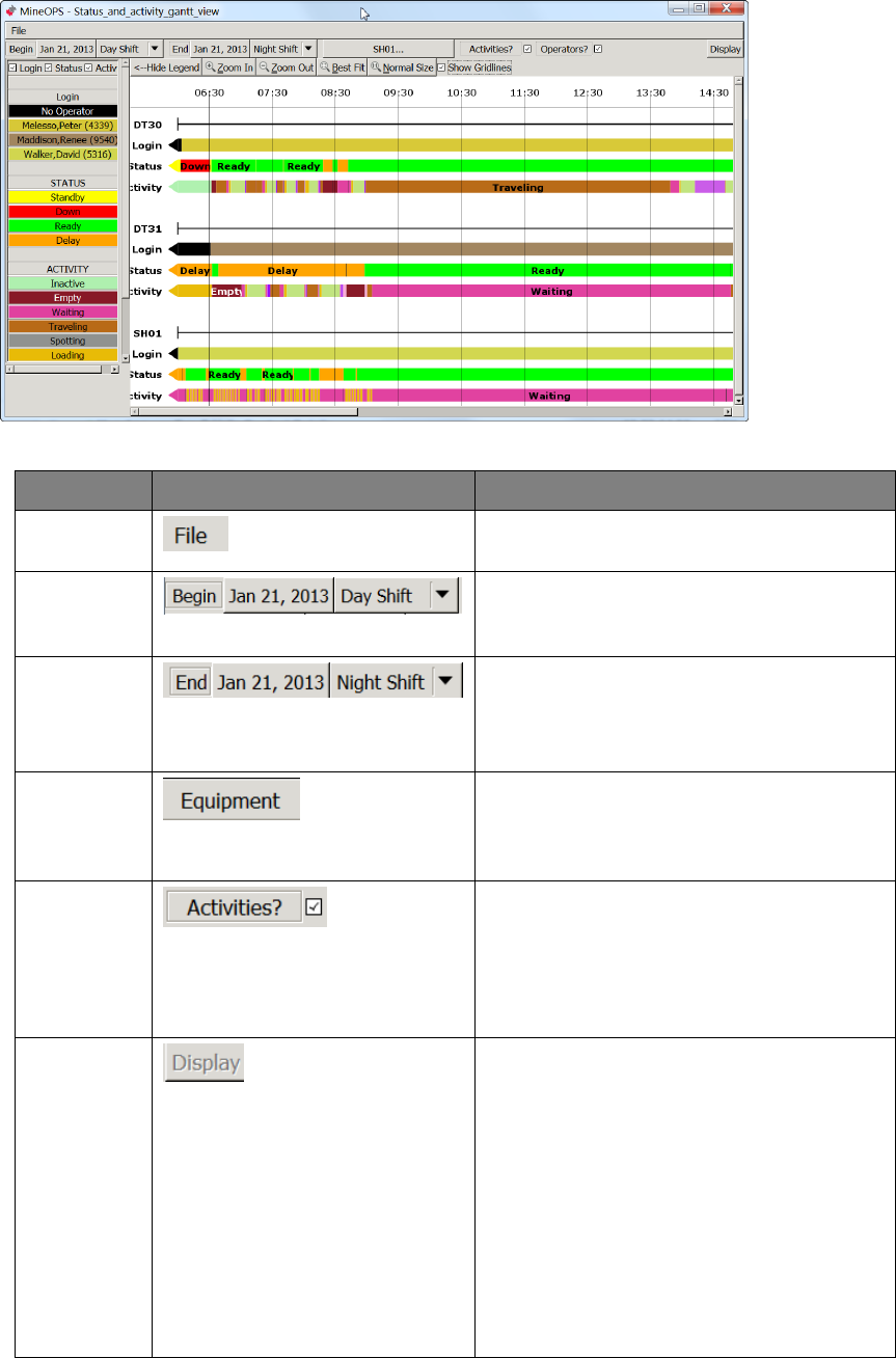
Commercial in Confidence
© Leica Geosystems
51
6.12.1.1 Status and Activity Gantt View
Example Status and Activity Gantt Chart View
Controls and Information displayed in the Status and Activity Gantt view includes:
Field
Display
Description
File
Provides the Close option to close the
view.
Begin
Buttons and drop-down menu to select the
start date and time. Selection of the Begin
date and shift is required.
End
Buttons and drop-down menu to select the
end date and time. Selection of the end
date and shift is required.
Equipment
Launches the equipment selection view to
allow the user to sort what equipment
history to view. Selection of the equipment
is required.
Activities
Checkbox
Displays a Gantt view of activities for the
selected equipment over the selected date
and time. View the activity entries by
grouping them according to Activity
category or by the user-defined time usage
model.
Display
Button
Loads the data requested into the Gantt
chart view. The display button is inactive
until a time frame and equipment are
selected.
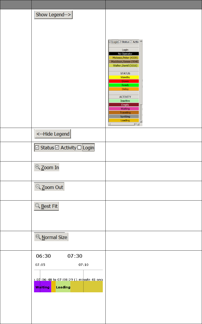
Commercial in Confidence
© Leica Geosystems
52
Field
Display
Description
Show
Legend
Displays the legend of the chart as
required. Legend colors match those
displayed on the Gantt chart. Login is
disabled by default. Use check boxes to
show and hide legend information.
Hide
Legend
Hides the Gantt chart legend.
Legend
check
boxes
Only shown when Show Legend is
selected. Select a check box to view the
required legend.
Zoom In
Zooms in by a factor of 50%. Select the
Zoom In button for incremental
magnification of the Gantt chart.
Zoom Out
Zooms out by a factor of 50%. Select the
Zoom Out to incrementally return to the
original view.
Best Fit
Allows the user to zoom in directly to a
section of Gantt chart. To view a section of
Gantt chart, select Best Fit. A selection
cursor appears, click and drag to define
the bounding box to view.
Normal Size
Returns the chart to the same
magnification level as when the chart
loaded.
Time Labels
and
Time labels resolve to appropriate time
spans (largest one hour, smallest 5
minutes) when zooming in and zooming
out of the Gantt view.
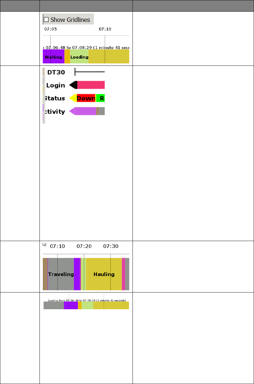
Commercial in Confidence
© Leica Geosystems
53
Field
Display
Description
Show
Gridlines
Displays time label gridlines.
Gantt chart
Equipment
Data
Gantt chart view of equipment can include
four rows:
Equipment – Equipment name. The
black line displays the extent of the
data available for that equipment for
that time range.
Login – A series of adjacent boxes
representing the user logged in to the
equipment. If no user is logged in, the
representative box is black.
Status – A series of adjacent boxes
representing the status of the machine.
Activity – A series of adjacent boxes
representing the activities of the
equipment.
Note:
If login, status, or activity data
is available beyond the time
range included in the chart,
the row starts or ends with an
arrow shape pointing in the
direction of the additional data.
Gantt chart
data block
element
A Gantt chart data block extends from its
start time, to the start time of the next data
item. If the data blocks are large enough,
they display a label.
Gantt
Element
Information
Move the cursor over the Gantt element to
view detail of the Gantt chart time chunk.
Information includes:
Element
Start time
End time
Duration
Note:
If there is no end time, the
element information does not
display.
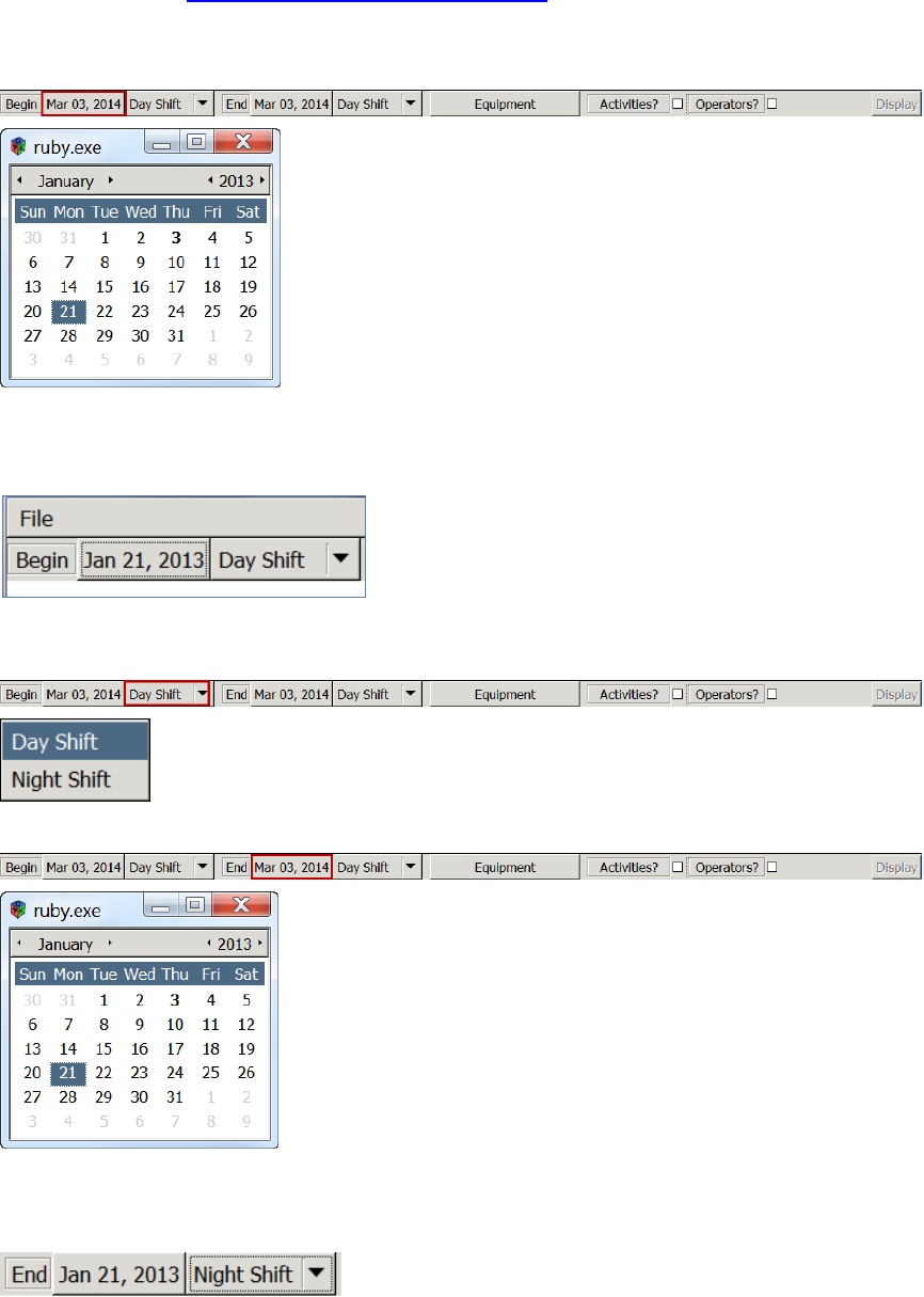
Commercial in Confidence
© Leica Geosystems
54
6.12.2 Load Data to Gantt View
1. Access the view. See Access Status and Activity Gantt View.
2. To load a range of data:
a. Select the Begin date field, the date calendar appears.
b. Use the arrows on each side of the month and year to select the required month and
year. Double-click on the day required. The Begin date is populated using the
required date.
c. To select the Begin shift, select the required starting shift from the Begin Shift
drop-down menu.
d. Select the End date field, the date calendar appears.
e. Use the arrows on each side of the month and year to select the required month and
year. Double-click on the day required. The End date is populated using the required
date.
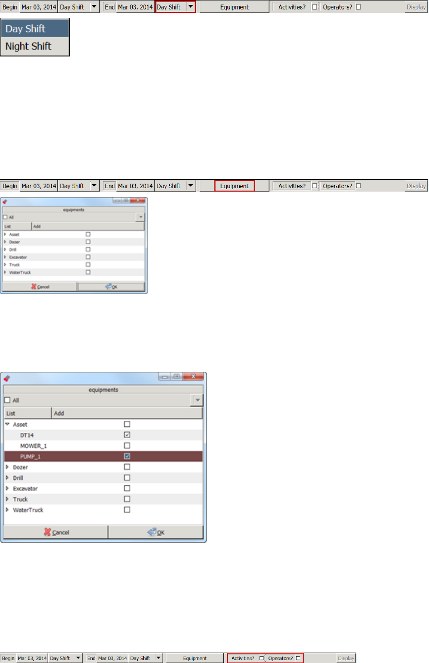
Commercial in Confidence
© Leica Geosystems
55
f. To select the ending shift, select the End Shift from the End Shift drop-down menu.
Note:
To view the activities or users’ log ins, ensure the Activities and/or Operators check
boxes are selected.
g. To select the equipment to view for the date range, select the Equipment button. The
Equipment view appears.
Note:
Only equipment for which data exists in the specified time range is included in the
equipment selection. Equipment with no data in the time range is not displayed.
h. Select the appropriate check box:
All check box – load all equipment data
Equipment Type check box – load all equipment of that type’s data
Use the arrow to the left of the equipment type to open the dropdown menu of
equipment to load data for individual equipment selected.
i. Select OK. The Display button on the Status and Activity Gantt view is enabled.
Note:
Viewing Activities and user log ins is optional. If neither Activities nor Operators
check boxes are selected, only machine data activity and Status is displayed on the
Gantt chart.
j. To view Activities or User data in the Gantt chart, select the Activities or Operators
check box as required.
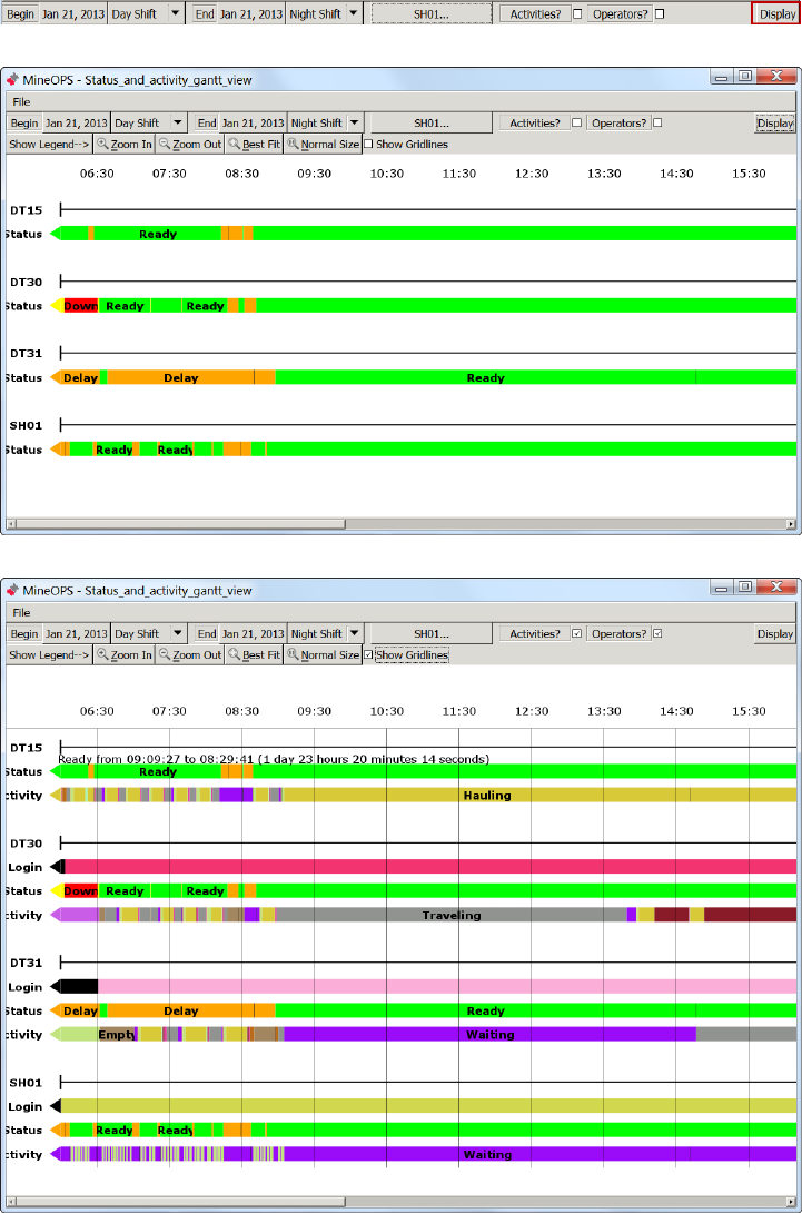
Commercial in Confidence
© Leica Geosystems
56
k. Select Display. The data loads and a set of view manipulation buttons and time
stamps appear across the top of the view.
Status and Activity Gantt View showing Equipment and Status
Status and Activity Gantt View showing Equipment, Status, Activities, and User data
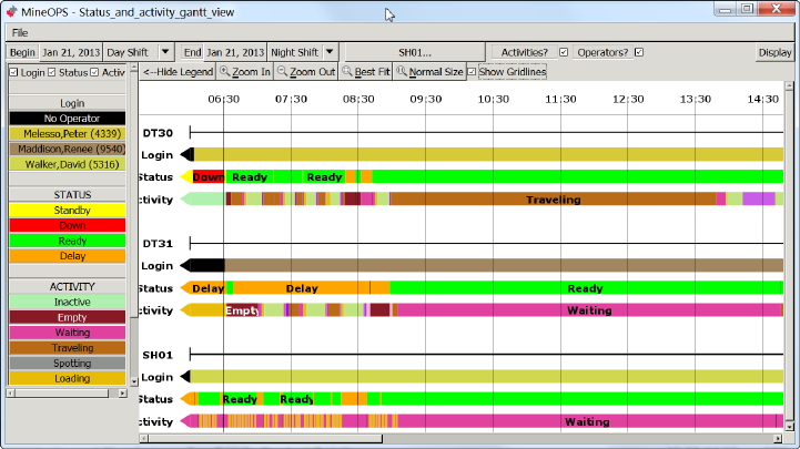
Commercial in Confidence
© Leica Geosystems
57
6.12.3 View Gantt Details
When the Gantt chart is populated with data, there may be sections of data in the chart that are
short or difficult to read. At the top left side of the chart are a number of controls associated with
viewing the chart.
Zoom In – Zooms in by a factor of 50%. The time labels at the top of the screen scale down to
fit the appropriate time range, to a minimum of 5 minutes.
Zoom Out – Zooms out by a factor of 50%.
Best Fit – Zooms in to view the selected area.
Normal Size – Zooms all the way back out to the original zoom level when the chart loaded.
6.12.4 Vertical Time Gridlines
Vertical time gridlines are aligned with each time label to provide visual approximation of event
timing. Time labels resolve to appropriate time spans (largest one hour, smallest 5 minutes) when
zooming in and zooming out of the Gantt view.
1. To view vertical gridlines select the Show Gridlines check box at the top of the chart.
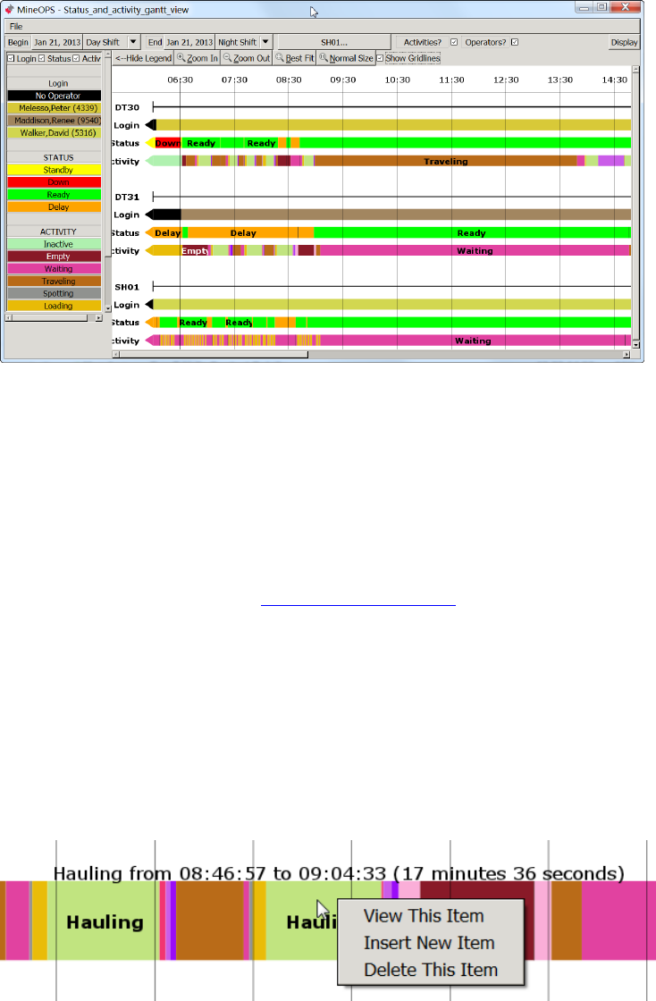
Commercial in Confidence
© Leica Geosystems
58
6.12.5 Gantt Legend
The legend panel is not visible when the data loads. The legend displays a list of statuses and
activities in assigned colors. The colors in the legend correspond to the boxes in the chart itself
and display the label for the item.
1. To view the legend, select Show Legend on the left hand side of the chart.
2. Logins are disabled in the legend by default. To view logins select the Login check box.
3. Hide any of the three legends (logins, statuses, and activities) from the legend panel by
unchecking the corresponding check box.
4. To hide the legend, select Hide Legend.
6.12.6 View, Edit, or Delete Data Detail on the Gantt View
Data appearing on the Gantt view can be viewed or modified.
Note:
While certain fields appear editable in the Status and Activity Gantt Data Detail view,
it is not recommended to change the Expected Time, Latitude, Longitude, or
Elevation of a data item. Please use standard Jmineops views for revising database
information.
6.12.6.1 View Data Detail
1. Load data into the Gantt view. See Load Data to Gantt View.
2. Data block details can be viewed by:
a. Left click on the block. The Data Detail view appears.
Caution:
Deleting an item cannot be undone.
b. Right-click on the data block to open the edit menu. Three options appear:
View This Item – the Data Detail view appears.
Insert New Item – the Data Detail view appears.
Delete This Item – the Delete confirmation dialog box appears.
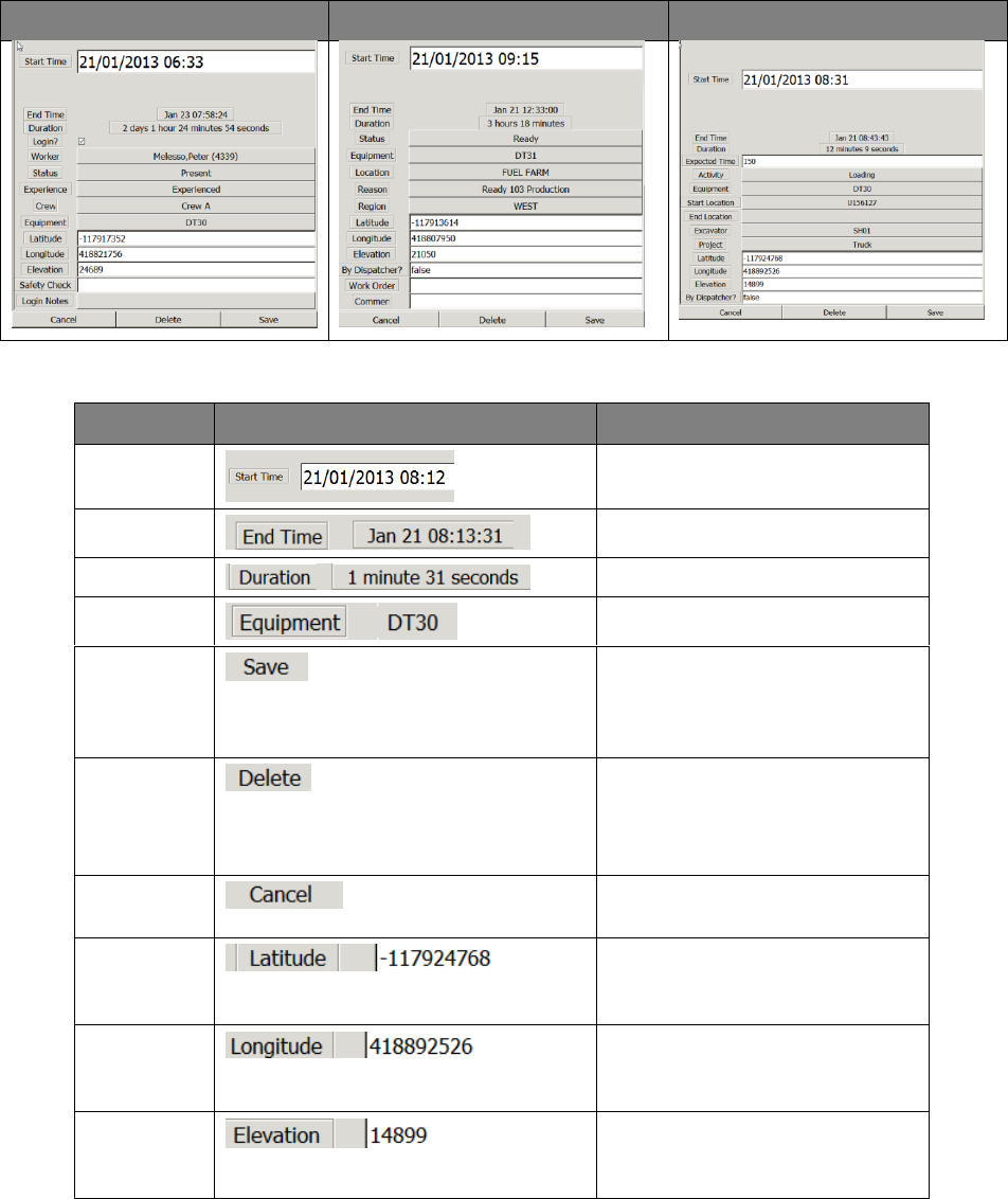
Commercial in Confidence
© Leica Geosystems
59
6.12.6.2 Data Detail View
Data detail views pull detail information from the database, therefore the contents of each detail
view may vary. Each view has common fields which are the same for each type of data, and data-
type specific fields. It is not recommended to assign an activity to a different piece of equipment,
or change equipment in the Gantt chart data detail views.
To change the content of a field, right-click on the value to open the drop-down menu for that
field.
Note:
Data appearing in this view is pulled from the database.
Login Data Detail view
Status Data Detail view
Activity Data Detail view
Common Data Detail View Fields
Field
Display
Description
Start Time
Start time of the data block.
End Time
End time of the data block.
Duration
Duration of the data.
Equipment
Applicable equipment.
Save button
Saves the data changes to the
database. Data changes must
be saved before doing other
work or the changes are lost.
Delete
button
Deletes the data block from the
database.
Data block deletion is
permanent.
Cancel
button
Cancels the changes and closes
the Data Detail view.
Latitude
Recorded equipment location
longitude at the specified point in
time.
Longitude
Recorded equipment location
latitude at the specified point in
time.
Elevation
Recorded equipment location
elevation at the specified point in
time.
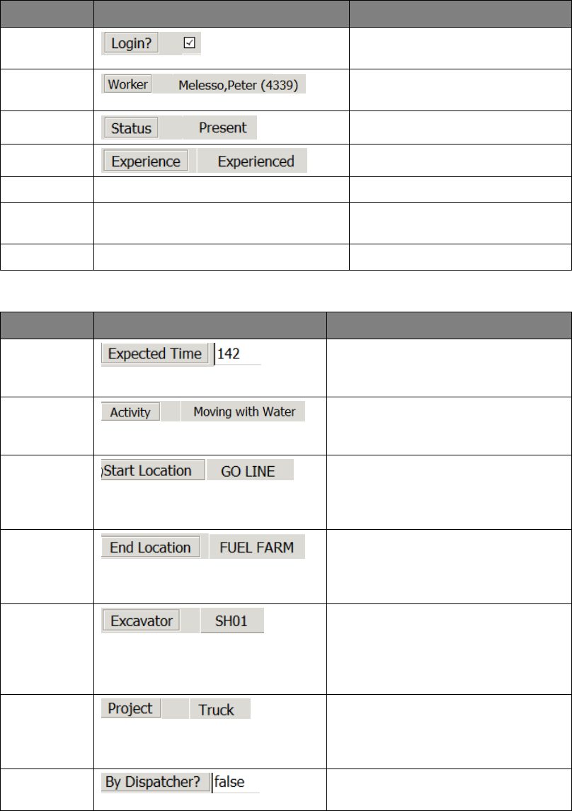
Commercial in Confidence
© Leica Geosystems
60
Login-Specific Data Detail Fields
Field
Display
Description
Login
Check box
Notes that there is a login for
that time.
Worker
Worker logged into the system at
that moment in time.
Status
Worker status.
Experience
Worker experience.
Crew
Crew the worker belongs to.
Safety
Check
Login Notes
Activity-Specific Data Detail Fields
Field
Display
Description
Expected
Time
Leica Jmineops Optimizer expected
time for the activity in seconds.
Don’t change the expected time.
Activity
Activity listed in the database. To
change the activity, right-click on the
activity to open the Activity menu.
Start
Location
Equipment location at the start of
the detail block. To change the Start
location, left-click on the location to
open the location menu.
End
Location
Equipment Location at the end of
the detail block. To change the End
location, left-click on the location to
open the location menu.
Excavator
Excavator ID if the equipment is
associated with an excavator. To
change the excavator, left-click on
the excavator to open the
equipment menu.
Project
Project to which the equipment is
associated. To change the project,
left-click on the project to open the
project menu.
By
Dispatcher?
If the assignment was made by the
Mine Controller.
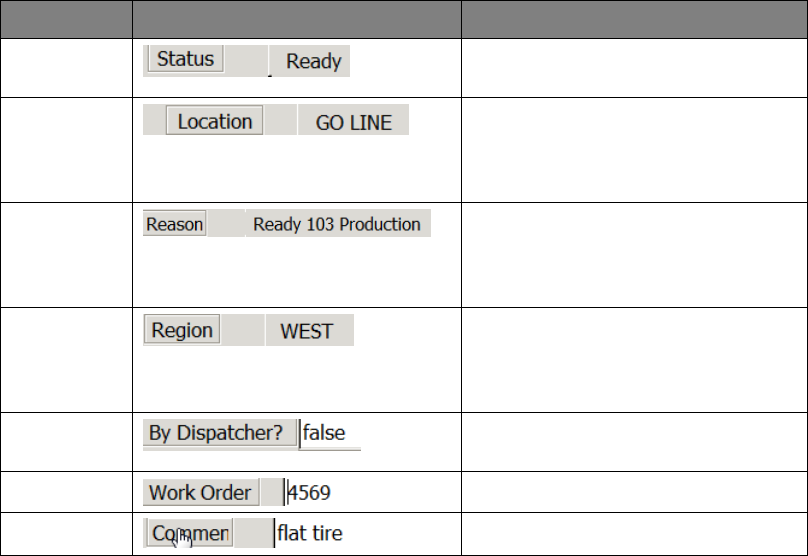
Commercial in Confidence
© Leica Geosystems
61
Status-Specific Data Detail Fields
Field
Display
Description
Status
Status reports the applicable
configured status for the data item.
Location
Equipment location at the start of
the detail block. To change the Start
location, left-click on the location to
open the location menu.
Reason
Status reason at the start of the
detail block. To change the reason,
left-click on the reason to open the
reason menu.
Region
Equipment location at the start of
the detail block. To change the
region location, left-click on the
region to open the location menu.
By
Dispatcher?
Work Order
Comment
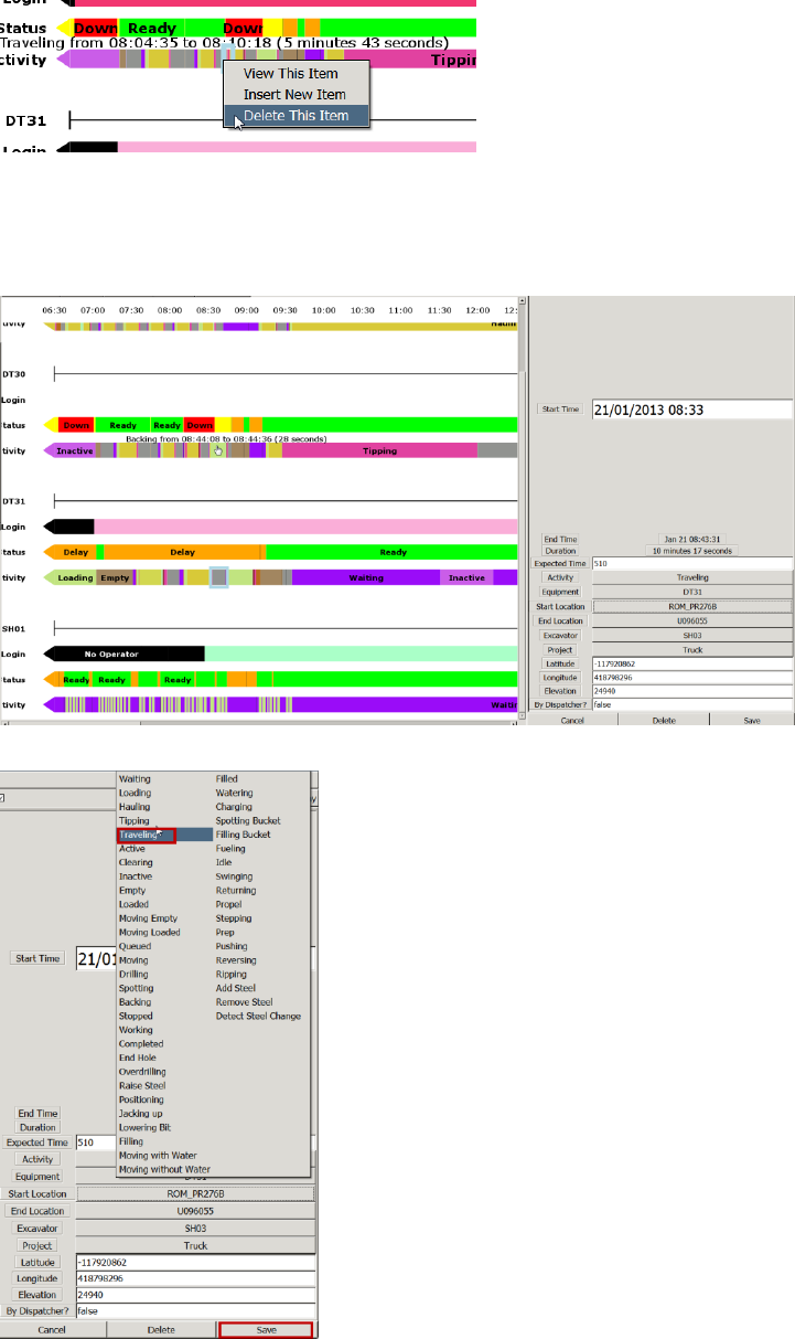
Commercial in Confidence
© Leica Geosystems
62
6.12.6.3 Edit Data Detail
1. Right-click on the data block, select View This Item. The item is highlighted and the Data
Detail view appears.
Note:
If Save is not selected before doing other work, all changes are lost.
2. To change the data detail, left-click on the information to open the related menu. Select the
required information.
3. Select Save.
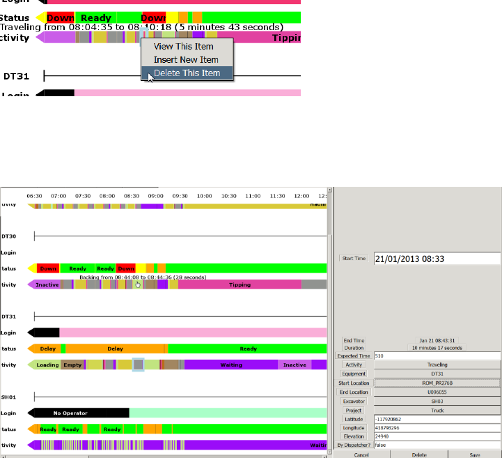
Commercial in Confidence
© Leica Geosystems
63
6.12.6.4 Insert Data
A data block extends from its own start time, to the start time of the next data item.
To insert a limited time item in the middle of another data item, insert the end time to split the
current block and insert the start time of the new item to start the new item. To insert a new item
from a certain time to the end time of a current item, only one start time must be added.
1. Select the place on the Gantt view to insert the new item. The data detail view appears. The
data listed on the view is an exact copy of the item selected. The time is populated with the
time indicated by the mouse cursor when the item was selected.
2. Right click on the data block, select Insert New Item. The item which is having an item
inserted into it is highlighted and the Data Detail view appears with the exact information for
the data block selected. The Start time is the time where the Gantt item was selected using
the mouse.
Note:
If Save is not selected before doing other work, all changes are lost.
3. Change the data detail as required, left-click on the information to open the related menu.
Select the required information.
4. Select Save. The new item is inserted
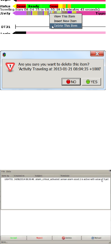
Commercial in Confidence
© Leica Geosystems
64
6.12.6.5 Delete Data
Caution:
Data block deletion is permanent. To reinstate a deleted data block, the entry
must be recreated using Insert New Item.
A data block extends from its own start time, to the start time of the next data item. Data blocks
may be deleted by viewing the item and selecting Delete from the Data view, or from the Gantt
chart view as follows:
1. Right click on the data block, select Delete This Item. The data item is highlighted and the
Delete item confirmation dialog box appears.
2. Select Yes. The item is deleted from the database. The earlier data block fills the space to the
start of the next data block.
Asset Alarms 6.13
If an asset alarm is configured, asset alarms are reported in the same manner as other Jmineops
equipment warnings and alarms.
Alarms are activated by sensor activity on the asset.
Sensors on the asset are activated when the sensor threshold levels change.
Asset thresholds can be configured to the following levels:
Minor – A low level alarm.
Urgent – A high level alarm
Critical – A very high level alarm
The Jasset alarm activates and sends a message to the user’s email inbox.
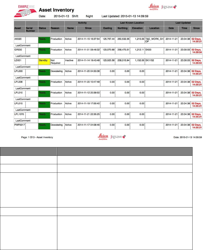
Commercial in Confidence
© Leica Geosystems
65
7 Leica Jview Jasset Reports
Leica Jview provides business intelligence reports on the assets in the Leica Jmineops system.
Jasset Inventory Report 7.1
The Jasset Inventory Report is a grid like report with a list of available assets and each asset’s
current status.
The report is navigable by type of asset and by individual asset.
The Last Updated (Since) field is shown in Red if when the report was executed, more than
30 minutes had passed since the asset’s record was last updated.
Example Jasset Inventory Report
Field
Description
Asset
The unique ID of the asset.
Serial Number
Optional serial number associated with the asset.
Status
The asset status:
Down.
Ready.
Standby.
Delay.
Reason
The function of the asset
Activity
The status of the asset and the time since the asset has been
active.
Name - Whether the status of the asset is active or
inactive.
Since - The time since the asset has been active.

Commercial in Confidence
© Leica Geosystems
66
Field
Description
Last Known Location
The location the asset was last logged as active in mine site
coordinates.
Easting - Easting Coordinate of asset in meters to five
decimal places.
Northing - Northing Coordinate of asset in meters to five
decimal places.
Elevation - Elevation of asset at time logged as active.
Location - Location of active asset at logged coordinate.
Last Updated
The date time and last logged active status of the asset:
Date - The date the asset was last updated.
Time - The time the asset was last updated.
Since - The last time the asset was logged with an active
status. The entry color denotes the time since the last
record update compared to when the report was run.
Black – the asset record was updated within 30
minutes of when the report was run.
Red- when the report was executed, more than
30 minutes had passed since the asset’s record
was updated.
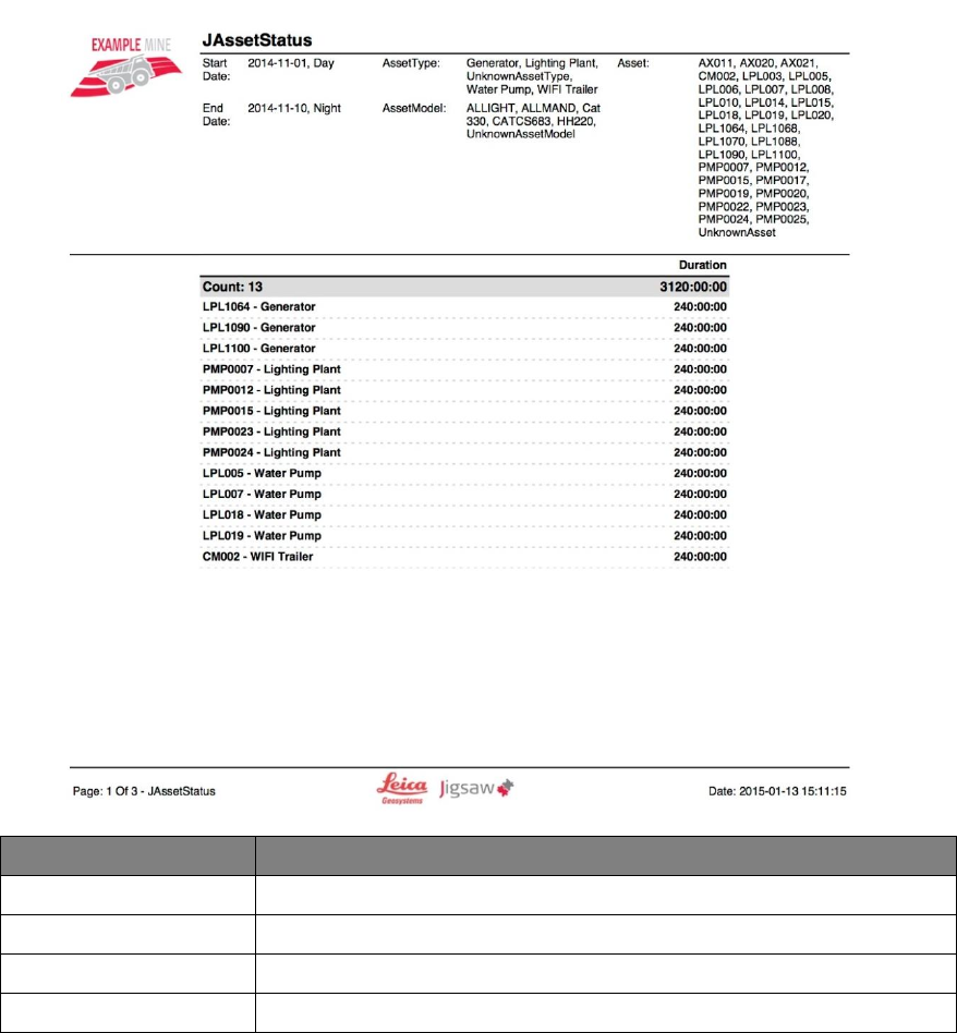
Commercial in Confidence
© Leica Geosystems
67
Jasset Status Report 7.2
The Jasset Status report provides asset status information aggregated for Asset, Day, and Shift
data fields. The report displays content in List, Bar Graph, and Pie Chart form.
Jasset Status Report Example
Field
Description
Asset
The ID of the asset
Day
The day the asset was logged
Status
The Down, Ready, Standby, Delay status
Reason
The function of the asset at the time of the report
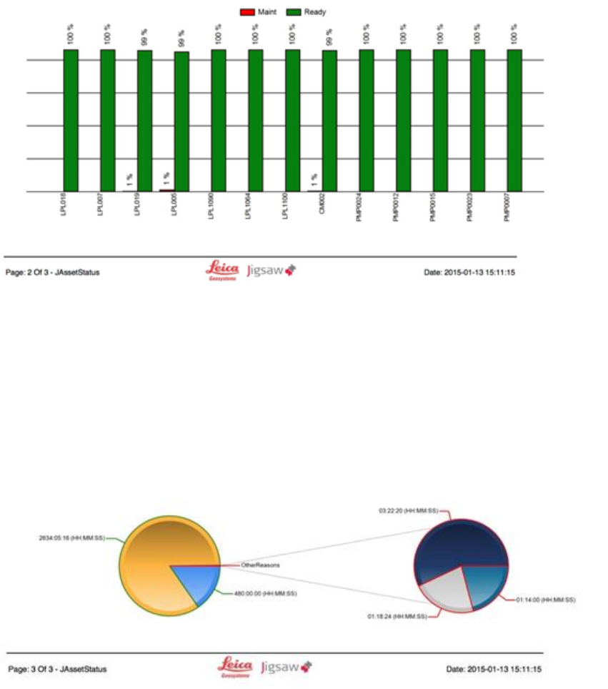
Commercial in Confidence
© Leica Geosystems
68
7.2.1 Duration Bar Graph
The Duration Bar graph charts the percent status events per asset for the given time period. It is
color coded with the default status display styles of the asset.
Duration Bar Graph
7.2.2 Pie Chart
The pie chart provides a chart of the reason codes and descriptions for all applicable assets
selected for the report's parameters. The outline of each reason slice is color coded to the asset
status color to which the reasons belong.
If certain reasons combine to less than 4% of all reasons, they are displayed as one slice called
Other Reasons.
Note:
Default display styles configuration is part of the system's standard installation
process. To change configuration, contact Leica Active Customer Care.
Pie Chart
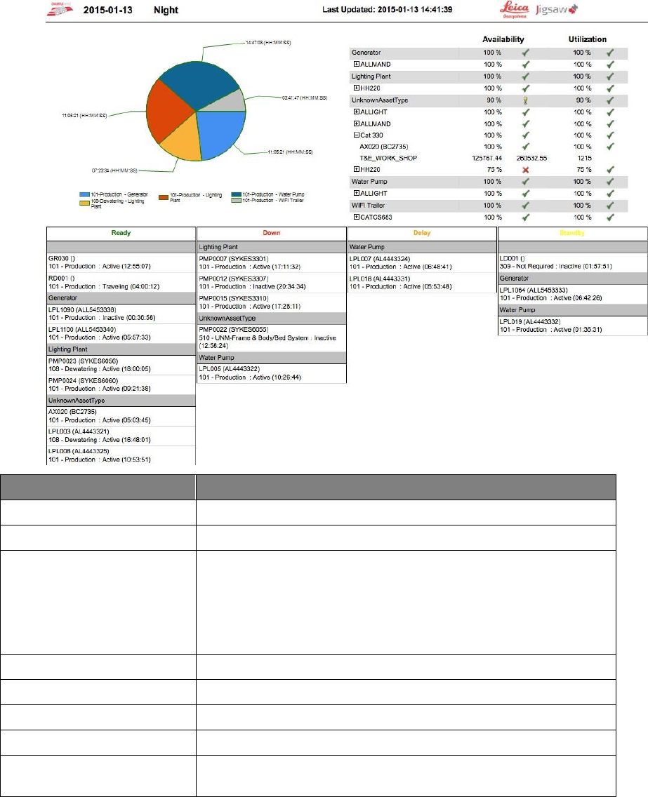
Commercial in Confidence
© Leica Geosystems
69
Jasset Dashboard 7.3
The Jasset dashboard provides general current event information about the asset. The Pie Chart:
charts reason codes and descriptions for all assets for the current shift. The outline of each slice
is color coded with the default status display color to which the reasons belong.
Note:
Default display styles configuration is part of the system's standard installation
process. To change configuration, contact Leica Active Customer Care.
Jasset Dashboard
Field
Description
Asset
The unique ID of the asset
Serial Number
Optional serial number associated with the asset
Status
The asset status:
Down
Ready
Standby
Delay
Reason
The function of the asset
Reason Code
The code associated with the function of the asset
Activity
The status of the asset and the time since it has been active
Activity Duration
The period the asset has been active
Last Known Location
The location the asset was last logged as active Coordinates and
Name
Commercial in Confidence
© Leica Geosystems
70
8 Care and Transport
Transport 8.1
When transporting the product by rail, air, or sea, always use the complete original Leica
Geosystems Mining packaging, cardboard box, or an equivalent, in order to protect the product
against shock and vibration.
Storage 8.2
Ensure the temperature limits are followed when storing the equipment, particularly in summer if
the equipment is inside a vehicle. Please reference the Technical Data section for information
about temperature limits.
Cleaning and Drying 8.3
8.3.1.1 Product and Accessories
Use only clean, soft, lint-free cloth for cleaning. If necessary, moisten the cloth with water or pure
alcohol. Do not use other liquids; these may attack the polymer components.
8.3.1.2 Connectors and Plugs
Keep plugs clean and dry. Blow away any dirt lodged in the plugs of the connecting cables.
Commercial in Confidence
© Leica Geosystems
71
9 Safety Directions
General Introduction 9.1
WARNING:
This is a Class A product. In a domestic environment this product may cause
radio interference in which case the user may be required to take adequate
measures.
The following directions should enable the person responsible for the product, and the person
who actually uses the equipment, to anticipate and avoid operational hazards.
The person responsible for the product must ensure that all users understand these directions
and adhere to them.
Intended Use 9.2
9.2.1 Permitted Uses
Jasset is intended for Mining use only.
Jasset is intended to be fitted to Mining assets only.
Data communication with external appliances as part of a Leica Jigsaw Mining Solution.
9.2.2 Adverse Use
Adverse use can lead to injury, malfunction, and damage. It is the task of the person responsible
for the equipment to inform the user about hazards and how to counteract them. The product is
not to be operated until the user has been instructed on how to work with it.
WARNINGS:
Unauthorized modification of Mining machinery by mounting or installing the
product may alter the function and safety of that mining machinery.
WARNING:
Follow the instructions of the machinery manufacturer. If no appropriate
instruction is available, ask the machinery manufacturer for instructions prior
to mounting or installing the product.
The following items result in adverse use.
Use of the product without instruction.
Use outside of the intended limits.
Disabling safety systems.
Removal of hazard notices.
Opening the product using tools, for example a screwdriver, unless this is specifically
permitted for certain functions.
Modification or conversion of the product.
Use after misappropriation.
Use of products with obviously recognizable damages or defects.
Use with accessories from other manufacturers without the prior explicit approval of Leica
Geosystems Mining.
Inadequate safeguards at the working site, for example when using on the intended site.
Limits of Use 9.3
9.3.1 Environment
Warning:
Not to be used on planes or any aircraft.
Warning:
Local safety authorities and safety experts must be contacted before working
in hazardous areas, or in close proximity to electrical installations or similar
situations by the person in charge of the product.
This product is suitable for use in an atmosphere appropriate for permanent human habitation.
Commercial in Confidence
© Leica Geosystems
72
Responsibilities 9.4
9.4.1 Manufacturer of the Product
Leica Geosystems Mining is responsible for supplying the product, including the User Manual and
original accessories, in a completely safe condition.
9.4.2 Manufacturers of Non-Leica Geosystems Mining Accessories
The manufacturers of non-Leica Geosystems Mining accessories for the product are responsible
for developing, implementing, and communicating safety concepts for their products, and are also
responsible for the effectiveness of those safety concepts in combination with the Leica
Geosystems Mining product.
9.4.3 Persons in Charge of the Product
WARNING:
The person responsible for the product must ensure that it is used in
accordance with the instructions. This person is also accountable for the
training and the deployment of personnel who use the product and for the
safety of the equipment in use.
The person in charge of the product has the following duties:
To understand the safety instructions on the product and the instruction in the User Manual.
To be familiar with local regulations relating to safety and accident prevention.
To ensure operators do not work within 30cm of the Cellular or Wi-Fi antennas.
To inform Leica Geosystems Mining immediately if the product and the application becomes
unsafe.
Hazards of Use 9.5
9.5.1 General Hazards
The absence of instruction, or the inadequate imparting of instruction, can lead to incorrect or
adverse use, and can give rise to accidents with far-reaching human, material, financial, and
environmental consequences.
All users must follow the safety directions given by the manufacturer and the directions of the
person responsible for the product.
Only Leica Geosystems Mining authorized service workshops are entitled to repair these
products.
Inadequate securing of the working site can lead to dangerous situations, for example in
traffic, on building sites, and at industrial installations.
Always ensure that the working site is adequately secured. Adhere to the regulations
governing safety and accident prevention and road traffic.
The user assures that the machine is operated, guided, and monitored by a qualified user
(e.g., a licensed driver). The user has been able to take emergency measures, for example
an emergency stop.
While providing information to the user of the machine, accidents may occur due to
The user not paying attention to the surroundings (people, ditches, traffic, etc.).
Malfunctions (of a system component interface, etc.).
9.5.2 Mechanical Hazards
Incorrect fastening of the equipment to vehicles or transporters poses the risk of the
equipment being broken by mechanical influence, vibration, or airstream. This may result in
accident and injury.
Periodically carry out test measurements and perform the field adjustments, particularly after
the product has been subjected to abnormal use and before and after important
measurements.
Commercial in Confidence
© Leica Geosystems
73
When setting up the product, ensure that the accessories are correctly adapted, fitted,
secured, and locked in position. Avoid subjecting the product to mechanical stress.
Attach the external antennae in accordance with installation instructions and applicable local
legal electrical installation code.
The external antennae must be secured additionally, for example by use of a safety cord.
Ensure that the mounting device is correctly attached and able to carry the weight of the
external antenna (> 1kg) safely.
Deflect the mechanically moving machine components as far as possible and define a safe
installation zone.
If the accessories used with the product are not properly secured and the product is subjected
to mechanical shock, for example, by blows or falling objects, the product may be damaged or
people may sustain injury.
9.5.3 Lightning Hazards
WARNING:
If the product is used with accessories, for example, masts, staffs, or poles,
you may increase the risk of being struck by lightning. Danger from high
voltages also exists near power lines. Lighting, voltage peaks, or the touching
of power lines can cause damage, injury, and death.
Be sure to remain at a safe distance from electrical installations. Do not use the product
directly under or in close proximity to power lines. If it is essential to work in such an
environment contact the safety authorities responsible for electrical installations and follow
their instructions.
To prevent damages due to indirect lightning strikes (voltage spikes) cables, for example for
antenna, power source or modem must be protected using appropriate protection elements,
like a lightning arrester. These instructions must be carried out by an authorized specialist.
If there is a risk of a thunderstorm, or if the equipment is to remain unused and unattended for
a long period, protect your product additionally by unplugging all systems components and
disconnecting all connecting cable and supply cables.
If the product has to be permanently mounted in an exposed location, it is advisable to
provide a lightning conductor for the product is given below. Always follow the regulations in
force by your country regarding grounding antennas and mast. These installations must be
carried out by an authorized specialist.
9.5.3.1 Lightning Conductors
Suggestions for design of a lightning conductor for a GNSS system follow:
9.5.3.1.1 On Non-Metallic Structures:
On Non-Metallic Structures, protection by air terminals is recommended.
1. An air terminal is a pointed solid or tubular rod of conducting material with mounting and
connection to a conductor.
2. The position of four air terminals must be uniformly distributed around the antenna at a
distance equal to the height of the air terminal. The air terminal diameter must be 12 mm for
copper or 15 mm for aluminum. The height of the air terminals must be 25 cm to 50 cm.
3. All air terminals must be connected to the down conductors. The diameter of the air terminal
must be kept to a minimum to reduce GNSS signal shading.
9.5.3.1.2 On Metallic Structures:
Protection is as described for non-metallic structures, but the air terminals can be connected
directly to the conducting structure without the need for down conductors.

Commercial in Confidence
© Leica Geosystems
74
9.5.4 Disposal
If the product is improperly disposed of, the following can happen:
If polymer parts are burnt, poisonous gases are produced, which may impair health.
By disposing of the product irresponsibly, unauthorized persons may use it in contravention of
the regulations, exposing themselves and third parties to the risk of severe injury and
rendering the environment liable to contamination.
Caution:
The product must not be disposed of with household waste. Dispose of
the product appropriately in accordance with the national regulations in force
in your country.
Always prevent access to the product by unauthorized personnel. Product
Specific treatment and waste management information can be downloaded
from the Leica Geosystems Mining home page at http://www.leica-
geosystems.com/treatment or obtained from your Leica Geosystems Mining
dealer.
Electromagnetic Compatibility (EMC) 9.6
The term Electromagnetic Compatibility is taken to mean the capability of the product to function
smoothly in an environment where electromagnetic radiation and electrostatic discharges are
present, and without causing electromagnetic disturbances to other equipment.
Electromagnetic radiation can cause disturbances in other equipment. Although the product
meets the strict regulations and standards that are enforced in this respect, Leica
Geosystems Mining cannot completely exclude the possibility that other equipment may be
disturbed.
There is risk that disturbances may be caused in other equipment if the product is used in
conjunction with accessories from other manufacturers, for example field computers, personal
computers, two-way radios, non-standard cables, or external batteries.
Use only the equipment and accessories recommended by Leica Geosystems Mining. When
combined with the product, they meet the strict requirements stipulated by the guidelines and
standards. When using computers and two-way radios, pay attention to the information about
electromagnetic compatibility provided by the manufacturer.
Disturbances caused by electromagnetic radiation can result in erroneous measurements.
Although the product meets the strict regulations and standards which are enforced in this
respect, Leica Geosystems Mining cannot completely exclude the possibility that the product
may be disturbed by very intense electromagnetic radiation produced by, for example, nearby
transmitters, two-way radios, or diesel generators.
Check the plausibility of results obtained under these conditions.
If the product is operated with connecting cables attached at only one of their two ends, the
permitted level of electromagnetic radiation may be exceeded and the correct functioning of
other products may be impaired.
While the product is in use, connecting cables must be connected at both ends.
Commercial in Confidence
© Leica Geosystems
75
10 Technical Data
Jasset W (Single Wi-Fi) Technical Data 10.1
10.1.1 Design
Industrial metal housing with a polymer top decal.
10.1.1.1 User Interface
Three LEDs
External display can be connected using ethernet
10.1.1.2 Dimensions
Length (cm)
Width (cm)
Height (cm)
15.1
16.6
4.8
10.1.1.3 Weight
Weight (kg)
1.0
10.1.1.4 Power
Consumption (W)
External Supply Voltage
7.2
Normal Voltage 24 VDC
Voltage Range 9 to 32 VDC
10.1.2 Environmental Specifications
10.1.2.1 Temperature
Operating Temperature (°C)
Storage Temperature (°C)
-30 to +65
-40 to +85
10.1.2.2 Protection Against Water, Dust, and Sand
Protection
IP66, IP 67 with fitted AMP
connector
10.1.2.3 Humidity
Protection
Up to 95%
The effects of condensation are to be effectively counteracted by periodically drying out the Jasset
module.
10.1.3 Interfaces
RS232 Serial: 2x
CAN: 2x
Ethernet: 1x
USB: 1x
Digital Inputs: 2x
Switched Output: 1x

Commercial in Confidence
© Leica Geosystems
76
10.1.4 Wireless Module Technical Data
10.1.4.1 Wi-Fi Module Technical Data
The Jasset Wi-Fi has the following Wi-Fi component.
2.4 GHz radio b/g/n compliant
Avg. TX Power 23 dBm
Receive Sensitivity -94 dBm @ 11 Mbps
10.1.5 Antenna Technical Data
10.1.5.1 Wi-Fi Antenna
Frequency: 2400-2483.5 MHz
Gain: 4.5 dBi
10.1.5.2 GNSS Antenna
GPS/GLONASS
Frequency: 1575.42-1606 MHz
LNA Gain: 28 dB min.
10.1.6 FCC Statement (Applicable for U.S.)
This equipment has been tested and found to comply with the limits for a Class A digital device,
pursuant to Part 15 of the FCC Rules. These limits are designed to provide reasonable protection
against harmful interference when the equipment is operated in a commercial environment. This
equipment generates, uses, and can radiate radio frequency energy and, if not installed and used
in accordance with the instruction manual, may cause harmful interference to radio
communications. Operation of this equipment in a residential area is likely to cause harmful
interference, in which case the user will be required to correct the interference at their own
expense.
This equipment generates, uses, and can radiate frequency energy and, if not installed and used
in accordance with the instructions, may cause harmful interference to radio communication.
However, there is no guarantee that interference will not occur in a particular installation. If this
equipment does cause harmful interference to radio or television reception, which can be
determined by turning the equipment off and on, the user is encouraged to try to correct the
interference by one or more of the following measures:
Reorient or relocate the receiving antenna (adhering to stated personal safety limits).
Increase the separation between the equipment and the receiver.
Connect the equipment into an outlet on a circuit different from that to which the receiver is
connected.
Consult the dealer or an experienced radio/TV technician for help.
Changes or modifications not expressly approved by Leica Geosystems for compliance could void
the user's authority to operate the equipment.
Jasset WW (Dual Wi-Fi) Technical Data 10.2
10.2.1 Design
Industrial metal housing with a polymer top decal.
10.2.1.1 User Interface
Three LEDs.
External display can be connected using ethernet
10.2.1.2 Dimensions
Length (cm)
Width (cm)
Height (cm)
15.1
16.6
4.8
Commercial in Confidence
© Leica Geosystems
77
10.2.1.3 Weight
Weight (kg)
1.0
10.2.1.4 Power
Consumption (W)
External Supply Voltage
7.2
Normal Voltage 24 VDC
Voltage Range 9 to 32 VDC
10.2.2 Environmental Specifications
10.2.2.1 Temperature
Operating Temperature (°C)
Storage Temperature (°C)
-30 to +65
-40 to +85
10.2.2.2 Protection Against Water, Dust, and Sand
Protection
IP66, IP 67 with fitted AMP connector
10.2.2.3 Humidity
Protection
Up to 95%
The effects of condensation are to be effectively counteracted by periodically drying out the Jasset
module.
10.2.3 Interfaces
RS232 Serial: 2x
CAN: 2x
Ethernet: 1x
USB: 1x
Digital Inputs: 2x
Switched Output: 1x

Commercial in Confidence
© Leica Geosystems
78
10.2.4 Wireless Module Technical Data
10.2.4.1 Wi-Fi Module Technical Data
The Jasset Wi-Fi has the following Wi-Fi component.
2.4 GHz radio b/g/n compliant
Avg. TX Power 23 dBm
Receive Sensitivity -94 dBm @ 11 Mbps
10.2.5 Antenna Technical Data
10.2.5.1 Wi-Fi Antenna
Frequency: 2400-2483.5 MHz
Gain: 4.5 dBi
10.2.5.2 GNSS Antenna
GPS/GLONASS
Frequency: 1575.42-1606 MHz
LNA Gain: 28 dB min.
10.2.6 FCC Statement (Applicable for U.S.)
This equipment has been tested and found to comply with the limits for a Class A digital device,
pursuant to Part 15 of the FCC Rules. These limits are designed to provide reasonable protection
against harmful interference when the equipment is operated in a commercial environment. This
equipment generates, uses, and can radiate radio frequency energy and, if not installed and used
in accordance with the instruction manual, may cause harmful interference to radio
communications. Operation of this equipment in a residential area is likely to cause harmful
interference, in which case the user will be required to correct the interference at their own
expense.
This equipment generates, uses, and can radiate frequency energy and, if not installed and used
in accordance with the instructions, may cause harmful interference to radio communication.
However, there is no guarantee that interference will not occur in a particular installation. If this
equipment does cause harmful interference to radio or television reception, which can be
determined by turning the equipment off and on, the user is encouraged to try to correct the
interference by one or more of the following measures:
Reorient or relocate the receiving antenna (adhering to stated personal safety limits).
Increase the separation between the equipment and the receiver.
Connect the equipment into an outlet on a circuit different from that to which the receiver is
connected.
Consult the dealer or an experienced radio/TV technician for help.
Changes or modifications not expressly approved by Leica Geosystems for compliance could void
the user's authority to operate the equipment.
Jasset G (Cellular) Technical Data 10.3
10.3.1 Design
Industrial metal housing with a polymer top decal.
10.3.1.1 User Interface
Three LEDs.
External display can be connected using ethernet
10.3.1.2 Dimensions
Length (cm)
Width (cm)
Height (cm)
15.1
16.6
4.8
Commercial in Confidence
© Leica Geosystems
79
10.3.1.3 Weight
Weight (kg)
1.0
10.3.1.4 Power
Consumption (W)
External Supply Voltage
7.2
Normal Voltage 24 Vdc
Voltage Range 9 to 32 Vdc
10.3.2 Environmental Specifications
10.3.2.1 Temperature
Operating Temperature (°C)
Storage Temperature (°C)
-30 to +65
-40 to +85
10.3.2.2 Protection Against Water, Dust, and Sand
Protection
IP66, IP 67 with fitted AMP connector
10.3.2.3 Humidity
Protection
Up to 95%
The effects of condensation are to be effectively counteracted by periodically drying out the
Jasset module.
10.3.3 Interfaces
RS232 Serial: 2x
CAN: 2x
Ethernet: 1x
USB: 1x
Digital Inputs: 2x
Switched Output: 1x
10.3.4 Wireless Module Technical Data
10.3.4.1 LTE/HSPA+/GPRS Wireless Module Technical Data
Type
Description
Technology
LTE Category 3 (100 Mbps downlink, 50 Mbps uplink)
UMTS with DC-HSPA+ Category 24 (42 Mbps downlink,5.76 Mbps uplink)
EDGE/GPRS (up to 236 kbps)
Bands
800/900/1800/2100/2600 MHz LTE
800/850/900/1900/2100 MHz HSPA+ (Power Class 3 (+24 dBm))
850/900 MHz GSM/GPRS/EDGE (GSM Power Class 4/EDGE E2)
1800/1900 MHz GSM/GPRS/EDGE (GSM Power Class 1/EDGE E2)
GPS/1575.42 MHz GLONASS/1602 MHz
Data Services
LTE Category 3 (100 Mbps downlink, 50 Mbps uplink)
UMTS/HSPA+/DC-HSPA+ Category 24 (42 Mbps downlink,5.76 Mbps uplink)
GSM/GPRS/EDGE (Downlink up to 236 kbps)

Commercial in Confidence
© Leica Geosystems
80
10.3.5 Antenna Technical Data
10.3.5.1 Cellular Antenna Technical Data
Frequency: 750-1250, 1650-2700 MHz
Peak Gain:
3 dBi @ 750-1250 MHz
5 dBi @ 1650-2000 MHz
3 dBi @ 2100-2700 MHz
10.3.5.2 GNSS Antenna
GPS/Glonass
Frequency: 1575.42-1606 MHz
LNA Gain: 28 dB min.
10.3.6 Conformity to National Regulations for Jasset G Variant
Hereby, Leica Geosystems Mining declares that Jasset is in compliance with the essential
requirements and other relevant provisions of Directive 1999/5/EC. The declaration of conformity
may be consulted at http://www.leica-geosystems.com/ce.
Class 1 equipment according to European Directive 1999/5/EC (R&TTE) can be
placed on the market and be put into service without restrictions in any EEA
Member state.
10.3.7 FCC Statement (Applicable for U.S.)
This equipment has been tested and found to comply with the limits for a Class A digital device,
pursuant to Part 15 of the FCC Rules. These limits are designed to provide reasonable protection
against harmful interference when the equipment is operated in a commercial environment. This
equipment generates, uses, and can radiate radio frequency energy and, if not installed and used
in accordance with the instruction manual, may cause harmful interference to radio
communications. Operation of this equipment in a residential area is likely to cause harmful
interference, in which case the user will be required to correct the interference at their own
expense.
This equipment generates, uses, and can radiate frequency energy and, if not installed and used
in accordance with the instructions, may cause harmful interference to radio communication.
However, there is no guarantee that interference will not occur in a particular installation. If this
equipment does cause harmful interference to radio or television reception, which can be
determined by turning the equipment off and on, the user is encouraged to try to correct the
interference by one or more of the following measures:
Reorient or relocate the receiving antenna (adhering to stated personal safety limits).
Increase the separation between the equipment and the receiver.
Connect the equipment into an outlet on a circuit different from that to which the receiver is
connected.
Consult the dealer or an experienced radio/TV technician for help.
Changes or modifications not expressly approved by Leica Geosystems for compliance could void
the user's authority to operate the equipment.
Jasset WG (Single Wi-Fi and Cellular) Technical Data 10.4
10.4.1 Design
Industrial metal housing with a polymer top decal.
10.4.1.1 User Interface
Three LEDs.
External display can be connected via ethernet
Commercial in Confidence
© Leica Geosystems
81
10.4.1.2 Dimensions
Length (cm)
Width (cm)
Height (cm)
15.1
16.6
4.8
10.4.1.3 Weight
Weight (kg)
1.0
10.4.1.4 Power
Consumption (W)
External Supply Voltage
7.2
Normal Voltage 24 Vdc
Voltage Range 9 to 32 Vdc
10.4.2 Environmental Specifications
10.4.2.1 Temperature
Operating Temperature (°C)
Storage Temperature (°C)
-30 to +65
-40 to +85
10.4.2.2 Protection Against Water, Dust, and Sand
Protection
IP66, IP 67 with fitted AMP connector
10.4.2.3 Humidity
Protection
Up to 95%
The effects of condensation are to be effectively counteracted by periodically drying out the Jasset
module.
10.4.3 Interfaces
RS232 Serial: 2x
CAN: 2x
Ethernet: 1x
USB: 1x
Digital Inputs: 2x
Switched Output: 1x
10.4.4 Wireless Module Technical Data
10.4.4.1 Wi-Fi Module Technical Data
The Jasset Wi-Fi has the following Wi-Fi components
2.4 GHz radio b/g/n compliant
Avg. TX Power 23 dBm
Receive Sensitivity -94 dBm @ 11 Mbps

Commercial in Confidence
© Leica Geosystems
82
10.4.4.2 LTE/HSPA+/GPRS Wireless Module Technical Data
Type
Description
Technology
LTE Category 3 (100 Mbps downlink, 50 Mbps uplink)
UMTS with DC-HSPA+ Category 24 (42 Mbps downlink,5.76 Mbps uplink)
EDGE/GPRS (up to 236 kbps)
Bands
800/900/1800/2100/2600 MHz LTE
800/850/900/1900/2100 MHz HSPA+ (Power Class 3 (+24 dBm))
850/900 MHz GSM/GPRS/EDGE (GSM Power Class 4/EDGE E2)
1800/1900 MHz GSM/GPRS/EDGE (GSM Power Class 1/EDGE E2)
GPS/1575.42 MHz GLONASS/1602 MHz
Data Services
LTE Category 3 (100 Mbps downlink, 50 Mbps uplink)
UMTS/HSPA+/DC-HSPA+ Category 24 (42 Mbps downlink,5.76 Mbps uplink)
GSM/GPRS/EDGE (Downlink up to 236 kbps)
10.4.5 Antenna Technical Data
10.4.5.1 Wi-Fi Antenna
Frequency: 2400-2483.5 MHz
Gain: 4.5 dBi
10.4.5.2 Cellular Antenna Technical Data
Frequency: 750-1250, 1650-2700 MHz
Peak Gain:
3 dBi @ 750-1250 MHz
5 dBi @ 1650-2000 MHz
3 dBi @ 2100-2700 MHz
10.4.5.3 GNSS Antenna
GPS/Glonass
Frequency: 1575.42-1606 MHz
LNA Gain: 28 dB min.
10.4.6 Conformity to National Regulations for Jasset G Variant
Hereby, Leica Geosystems Mining declares that Jasset is in compliance with the essential
requirements and other relevant provisions of Directive 1999/5/EC. The declaration of conformity
may be consulted at http://www.leica-geosystems.com/ce.
Class 1 equipment according to European Directive 1999/5/EC (R&TTE) can be
placed on the market and be put into service without restrictions in any EEA
Member state.
10.4.7 FCC Statement (Applicable for U.S.)
This equipment has been tested and found to comply with the limits for a Class A digital device,
pursuant to Part 15 of the FCC Rules. These limits are designed to provide reasonable protection
against harmful interference when the equipment is operated in a commercial environment. This
equipment generates, uses, and can radiate radio frequency energy and, if not installed and used
in accordance with the instruction manual, may cause harmful interference to radio
communications. Operation of this equipment in a residential area is likely to cause harmful
interference, in which case the user will be required to correct the interference at their own
expense.
This equipment generates, uses, and can radiate frequency energy and, if not installed and used
in accordance with the instructions, may cause harmful interference to radio communication.
However, there is no guarantee that interference will not occur in a particular installation. If this
Commercial in Confidence
© Leica Geosystems
83
equipment does cause harmful interference to radio or television reception, which can be
determined by turning the equipment off and on, the user is encouraged to try to correct the
interference by one or more of the following measures:
Reorient or relocate the receiving antenna (adhering to stated personal safety limits).
Increase the separation between the equipment and the receiver.
Connect the equipment into an outlet on a circuit different from that to which the receiver is
connected.
Consult the dealer or an experienced radio/TV technician for help.
Changes or modifications not expressly approved by Leica Geosystems for compliance could void
the user's authority to operate the equipment.
Jasset WWG (Dual Wi-Fi and Cellular) Technical Data 10.5
10.5.1 Design
Industrial metal housing with a polymer top decal.
10.5.1.1 User Interface
Three LEDs.
External display can be connected via ethernet
10.5.1.2 Dimensions
Length (cm)
Width (cm)
Height (cm)
15.1
16.6
4.8
10.5.1.3 Weight
Weight (kg)
1.0
10.5.1.4 Power
Consumption (W)
External Supply Voltage
7.2
Normal Voltage 24 Vdc
Voltage Range 9 to 32 Vdc
10.5.2 Environmental Specifications
10.5.2.1 Temperature
Operating Temperature (°C)
Storage Temperature (°C)
-30 to +65
-40 to +85
10.5.2.2 Protection Against Water, Dust, and Sand
Protection
IP66, IP 67 with fitted AMP connector
10.5.2.3 Humidity
Protection
Up to 95%
The effects of condensation are to be effectively counteracted by periodically drying out
the Jasset module.

Commercial in Confidence
© Leica Geosystems
84
10.5.3 Interfaces
RS232 Serial: 2x
CAN: 2x
Ethernet: 1x
USB: 1x
Digital Inputs: 2x
Switched Output: 1x
10.5.4 Wireless Module Technical Data
10.5.4.1 Wi-Fi Module Technical Data
The Jasset Wi-Fi has the following Wi-Fi components:
2.4 GHz radio b/g/n compliant
Avg. TX Power 23 dBm
Receive Sensitivity -94 dBm @ 11 Mbps
10.5.4.2 LTE/HSPA+/GPRS Wireless Module Technical Data
Type
Description
Technology
LTE Category 3 (100 Mbps downlink, 50 Mbps uplink)
UMTS with DC-HSPA+ Category 24 (42 Mbps downlink,5.76 Mbps uplink)
EDGE/GPRS (up to 236 kbps)
Bands
800/900/1800/2100/2600 MHz LTE
800/850/900/1900/2100 MHz HSPA+ (Power Class 3 (+24 dBm))
850/900 MHz GSM/GPRS/EDGE (GSM Power Class 4/EDGE E2)
1800/1900 MHz GSM/GPRS/EDGE (GSM Power Class 1/EDGE E2)
GPS/1575.42 MHz GLONASS/1602 MHz
Data Services
LTE Category 3 (100 Mbps downlink, 50 Mbps uplink)
UMTS/HSPA+/DC-HSPA+ Category 24 (42 Mbps downlink,5.76 Mbps uplink)
GSM/GPRS/EDGE (Downlink up to 236 kbps)
10.5.5 Antenna Technical Data
10.5.5.1 Wi-Fi Antenna
Frequency: 2400-2483.5 MHz
Gain: 4.5 dBi
10.5.5.2 Cellular Antenna Technical Data
Frequency: 750-1250, 1650-2700 MHz
Peak Gain:
3 dBi @ 750-1250 MHz
5 dBi @ 1650-2000 MHz
3 dBi @ 2100-2700 MHz
10.5.5.3 GNSS Antenna
GPS/Glonass
Frequency: 1575.42-1606 MHz
LNA Gain: 28 dB min.
10.5.6 Conformity to National Regulations for Jasset G Variant
Hereby, Leica Geosystems Mining declares that Jasset is in compliance with the essential
requirements and other relevant provisions of Directive 1999/5/EC. The declaration of conformity
may be consulted at http://www.leica-geosystems.com/ce.

Commercial in Confidence
© Leica Geosystems
85
Class 1 equipment according to European Directive 1999/5/EC (R&TTE) can be
placed on the market and be put into service without restrictions in any EEA
Member state.
10.5.7 FCC Statement (Applicable for U.S.)
This equipment has been tested and found to comply with the limits for a Class A digital device,
pursuant to Part 15 of the FCC Rules. These limits are designed to provide reasonable protection
against harmful interference when the equipment is operated in a commercial environment. This
equipment generates, uses, and can radiate radio frequency energy and, if not installed and used
in accordance with the instruction manual, may cause harmful interference to radio
communications. Operation of this equipment in a residential area is likely to cause harmful
interference, in which case the user will be required to correct the interference at their own
expense.
This equipment generates, uses, and can radiate frequency energy and, if not installed and used
in accordance with the instructions, may cause harmful interference to radio communication.
However, there is no guarantee that interference will not occur in a particular installation. If this
equipment does cause harmful interference to radio or television reception, which can be
determined by turning the equipment off and on, the user is encouraged to try to correct the
interference by one or more of the following measures:
Reorient or relocate the receiving antenna (adhering to stated personal safety limits).
Increase the separation between the equipment and the receiver.
Connect the equipment into an outlet on a circuit different from that to which the receiver is
connected.
Consult the dealer or an experienced radio/TV technician for help.
Changes or modifications not expressly approved by Leica Geosystems for compliance could void
the user's authority to operate the equipment.
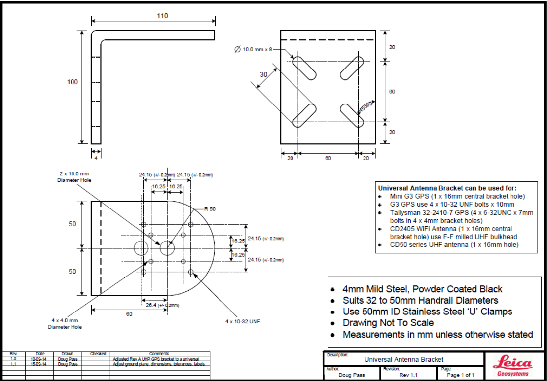
Commercial in Confidence
© Leica Geosystems
86
11 Appendix A – Universal Antenna Bracket

Commercial in Confidence
© Leica Geosystems
87
12 Appendix B – Back Up Power Supply
The requirement for the Battery Back-up is 48 hours min (up to 10 days in power saving mode).
Battery Requirements
Solar Panel Requirements
Required Jasset battery on
time = 48 Hrs
Australia Worse case
hours sunshine / day
(Melbourne) =
3
hrs
Recommended maximum
battery discharge = 50% (Lead
Acid)
Full Power Mode
Recommended maximum
battery discharge = 100%
(Lithium Ion)
Daily consumed Amp
hours = 24 hrs x 600 mA
=
14.4
Ahrs
Full Power Mode
Hourly charge rate =
Daily consumed Amp
hours / No of charge
hours =
4.8
A
Estimated/Measured nominal
power = 600 mA @ 12 V,
300 mA at 24 V
Solar Panel Power rating
= Minimum hourly charge
rate x Battery Voltage =
57.6
W
Battery Requirement (Amp
Hours) = 48 x 0.6 / 0.5 =
57.6
Ahrs
(Lead
Acid)
Low Power Mode
Low Power Mode
Daily consumed Amp
hours = 24 hrs x 100 mA
=
2.4
Ahrs
Estimated/Measured average
power = 100 mA @ 12 V,
50 mA at 24 V
Hourly charge rate =
Daily consumed Amp
hours / No of charge
hours =
0.8
A
Battery Requirement (Amp
Hours) = 48 x 0.1 / 0.5 =
9.6
Ahrs
(Lead
Acid)
Solar Panel Power rating
= Minimum hourly charge
rate x Battery Voltage =
9.6
W
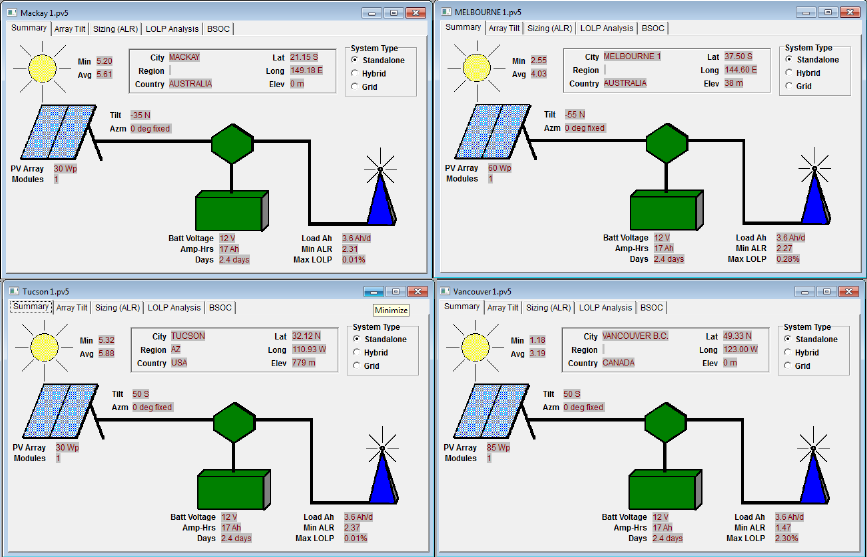
Commercial in Confidence
© Leica Geosystems
88
Solar Panel Calculations - Using BP Solar Application 12.1
The BP Solar application incorporates local weather patterns in addition to the expected latitude
and longitude to determine the hours of sun and day, and the sun’s intensity during those hours.
The application also calculates the efficiency of the solar panel dependent on the sun’s intensity,
and the tilt angle of the solar panel.
The calculations below demonstrate the differences for locations in Australia and North America
using this application. LOLP stands for Loss Of Load Probability. For our application this should
ideally be 0%, to ensure 24hour power 365 days a year. The calculations for determining the
optimum Solar Panel size have therefore set the minimum power for obtaining this 0% LOLP.
12.1.1 Battery Size
Full Power Mode Capacity:
Referring to calculations above, battery capacity has been determined to be 57.6 AHrs, @ 12 V.
Low Power Mode Capacity:
Referring to calculations above, battery capacity has been determined to be 9.6 AHrs, @ 12 V.
Physical size:
Approx. 0.1x0.1x0.15 m
Full Power Battery Size:
12 V, 57.6 AHrs equates to a battery size of approx. 240 mm x 180 mm x 185 mm, with a weight
of approx. 20 kg
Low Power Battery Size:
12 V, 9.6 AHrs equates to a battery size of approx. 151 mm x 98 mm x 97.5 mm, with a weight of
approx. 4 kg (The Yuasa NP12-12 used on the test systems)
Commercial in Confidence
© Leica Geosystems
89
Power-saving mode:
Jasset is designed to run in low-power mode constantly for anything that uses solar panels
(portable toilets, etc.). For other use cases where power is available for a portion of the time
(lighting plants running on generators at night and off during the day), it needs to connect to a
switch from the power source to know when it is on or off. It is run in full power mode when
the power source is connected and run in low-power mode when it is disconnected.
There are requirements for some functions, e.g. turning on/off lights, monitoring input and
sensing movement that are not be available during power-saving (standby) mode. The only
way to perform these functions is to operate Jasset in full-power mode in order to run the
business logic.
For monitoring inputs, this can be done in power-saving mode on a planned schedule. For
example, it can run in standby mode for 50 minutes, and then turn on the CPU for full power
mode to get position update, orientation, monitor inputs and switch outputs. Once these
operations are complete, it goes back into standby mode for another 50 minutes.
In Low power mode the functionality is not available or is only available during the Power-up
time.
Commercial in Confidence
© Leica Geosystems
90
13 Appendix C - Jasset FCC Maximum Personal
Exposure (MPE) Calculations
The following appendix is provided for reference.
Reference: FCC document ‘Evaluating Compliance with FCC Guidelines for Human Exposure to
Radiofrequency Electromagnetic Fields. From here in this document will be referred to as the
FCC Guidline to MPE document.
Jasset Intentional Radiators 13.1
The Jasset WWG comprises the following RF interfaces
13.1.1 Wi-Fi
Radio : Zcomax ZCN-722M 802.11b/g/n USB module
Antenna: RFI CD2405 collinear, 4.5dBi, 2400GHz to 2500MHz.
Refer documents ZCN-722M Technical Specification and the CD2405 data sheet for further
information.
13.1.2 4G
Radio: Sierra Wireless MC7354 PCI Express 4G module
Antenna: RM-WLF-DN-BLK; antenna gain 3dBi, 694MHz to 894MHz and 1.7GHz to 2.7GHz.
Refer documents AirPrime MC7354 Technical Specification and RM-WLF Antenna Specification
for further information.
MPE Calculations 13.2
MPE Formula
The FCC Guide to MPE document section 3 ‘Methods of Predicting Human Exposure’ page 17,
advises to use the following formula
S = P. G / 4.π.R2
R = ( P.G / 4.π.S )0.5
Where
S = Power Density (MPE) mW/cm2
P = Power input to antenna (power output from radio) (mW)
G = Power gain of antenna relative to isotropic radiator (dBi)
R = Distance from antenna (cm)
13.2.1 WiFi MPE Calculations
Referring to The FCC Guide to MPE document, Appendix A, Table 1 (B) Limits for General
Population/Uncontrolled exposure (1.5GHz to 100GHz).
S = 1.0 mW/cm2
P = 23dB = 200mW (ref ZCN-722M data sheet)
G = 4.5dBi (ref RFI CD2405 data sheet)
R = ( P.G / 4.π.S )0.5
R = ( 200 x 4.5 / 4.π . 1)0.5
R = 8.5 cm
13.2.2 4G MPE Calculations
The MC7354 transmits at different power levels dependant on its transmit frequency. The
calculations shown here are for the worst case scenario (Maximum required R)
Commercial in Confidence
© Leica Geosystems
91
Referring to The FCC Guide to MPE document, Appendix A, Table 1 (B) Limits for General
Population/Uncontrolled exposure (300MHz to 1500MHz).
S = f/1500 = 850/1500 = 0.57 mW/cm2
P = 32dBm = 1585mW (ref MC7354 data sheet, Table 4-10 Conducted Tx power tolerances.)
G = 3dBi (ref RM-WLF-DN-BLK data sheet)
R = ( P.G / 4.π.S )0.5
R = ( 1585 x 3 / 4.π. 0.57 )0.5
R = 25.76 cm

Commercial in Confidence
© Leica Geosystems
92
14 Glossary
Term
Definition
CAN
Controller Area Network
GNSS
Global Navigation Satellite System
GPIO
General Purpose Input/Output
GPS
Global Positioning System
HSPA
High Speed Packet Access
IP
Internet Protocol

United States, Canada & Mexico
Leica Geosystems Mining
Tucson, USA
Ph: +1 520 529 8729
Latin America
Leica Geosystems Mining
Santiago, Chile
Ph: +56 2 224 9512
Australia & South-East Asia
Leica Geosystems Mining
Brisbane, Australia
Ph: +61 7 3117 8900
Africa
Leica Geosystems Mining
Johannesburg, South Africa
Ph: +27 11 594 3900
China
Leica Geosystems Mining
Beijing, China
Ph: +86 10 8569 1819
India
Leica Geosystems Mining
Gurgaon, India
Ph: +91 124 412 2222
Indonesia
PT Leica Geosystems
Balikpapan, Indonesia
Ph: +62 811 544 1258
Email:
miningsales@leica-geosystems.com
www.leica-geosystems.com/mining
Leica Geosystems’ next-generation Leica Jigsaw monitoring and GPS guidance solution
unearths site productivity with a revolutionary product range for
draglines, blast-hole drills, electric shovels, dozers, excavators, haul trucks,
loaders and auxiliary assets.
State-of-the-art real-time analysis and reporting software gives entire sites
the tools that they need to stay on top by efficiently controlling resources and equipment.
The result? Informed decision making, optimized productivity and unparalleled
performance for maximum site output.
Backed up by a reliable global service and support network, Leica Geosystems
Mining provides you with one seamlessly integrated and efficient
Mine Management Solution.
When it has to be right.