Hexing Electrical MJN901 Single Phase HexNet User Manual
Hexing Electrical Co.,Ltd Single Phase HexNet Users Manual
Users Manual

Single Phase HexNet
(MJN901)
User Manual
Version Maker Date
V0.0.1 WangGang 2017.01.20
HexingElectricalCo.,Ltd.
〉〉〉Single Phase HexNet(MJN901)
1.Product Introduction
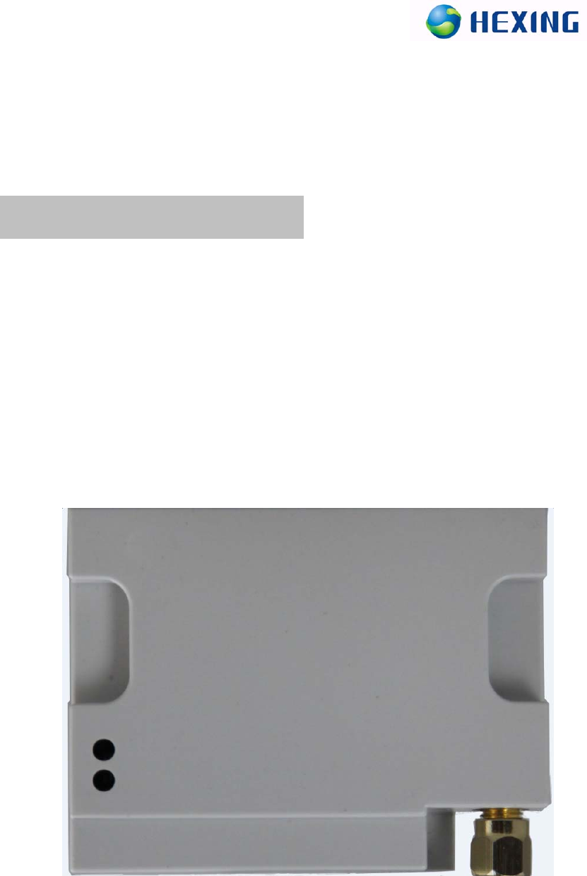
The Single Phase HexNet is a highly integrated half-duplex micropower
wireless data transmission device.The Single Phase HexNet embedded
high-performance RF chip.User programming has very good flexibility. This
device operating frequency include 916.25-926.65MHz. The real figure as
shown in the figure below.
This Single Phase HexNet is mainly used in power system, electricity
information collection system.Mainly include the following equipments:
Data Collector,Smart Electric Meter,etc.
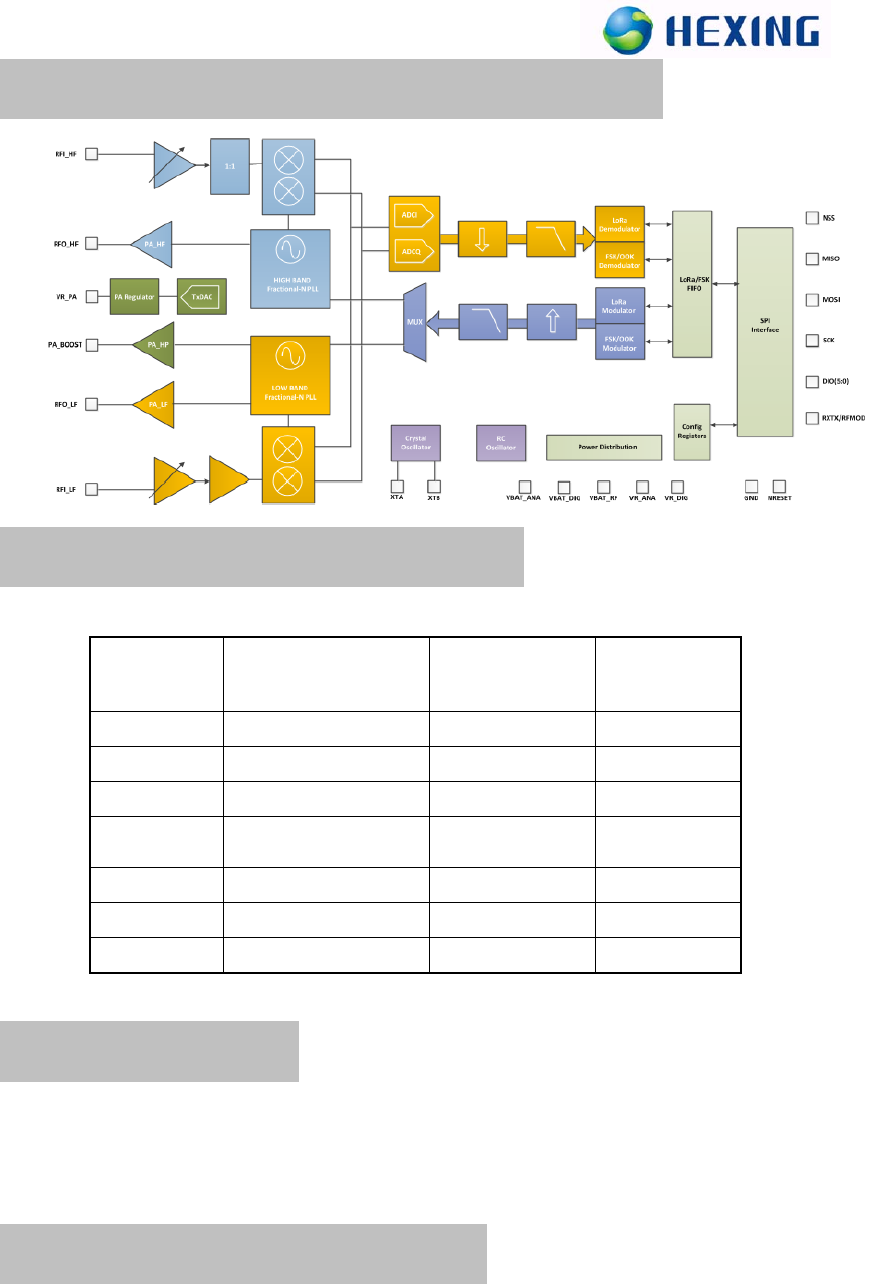
2.RF Module Chip Block Diagram
3.RF Module Pin Definition
Pin number Signal nameSignal categorySignal direction
1,2VCCPowerI
3,4VCCPowerI
5TXDUarttransmitPinO
6RXDUartreceivePinI
7D3.3VPowerO
8/RSTRESETPinI
9/N
5. RF operation
Insert the HexNet on user’s device,can use uart to communicate with HexNet
device.User don’t change anyting of the device,they will very easy to set up their
communication network.
6. Installation instructions
1)Please insert MJN901 on the corresponding interface, and ensure the pin interface
definitions are consistent with MJN901.
2)Interfaces are defined as follows:
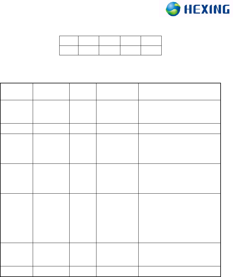
13579
2468
PIN
PIN Interface
definition
Signal
category DirectionDescription
1,2VCCPower
Communicationmoduleanalog
partofthepowersupply,voltageis
5vto15V.
3,4GNDGNDGND
5TXDSignalO
Communicationmoduledata
(TTL3.3Vlevel),serialport
communicatingwiththebase
table.Sendfrommodule
6RXDSignalI
Communicationmoduledata
reception(3.3VTTLlevel),serial
portcommunicatingwiththebase
table.Receivetomodule
7D3.3VPower
Powerprovidedbythemodule,
communicationmoduleofdigital
partofpower,voltageof3.3V+/‐
5%,theminimumcurrent50ma,
withVCCpowersupply,the
isolationopticalcouplingusedto
drivethecommunicationinterface.
8/RSTResetI
Resetmodule(lowleveleffectively,
effectiveleveltime100
milliseconds)
9///Reserved
3)Equipment flip cover and seal
4)Terminal equipment using the lid well
5)Provide equipment machine right alternating current (AC) on the site
6)Equipment terminal cover screw to play well, and make seal
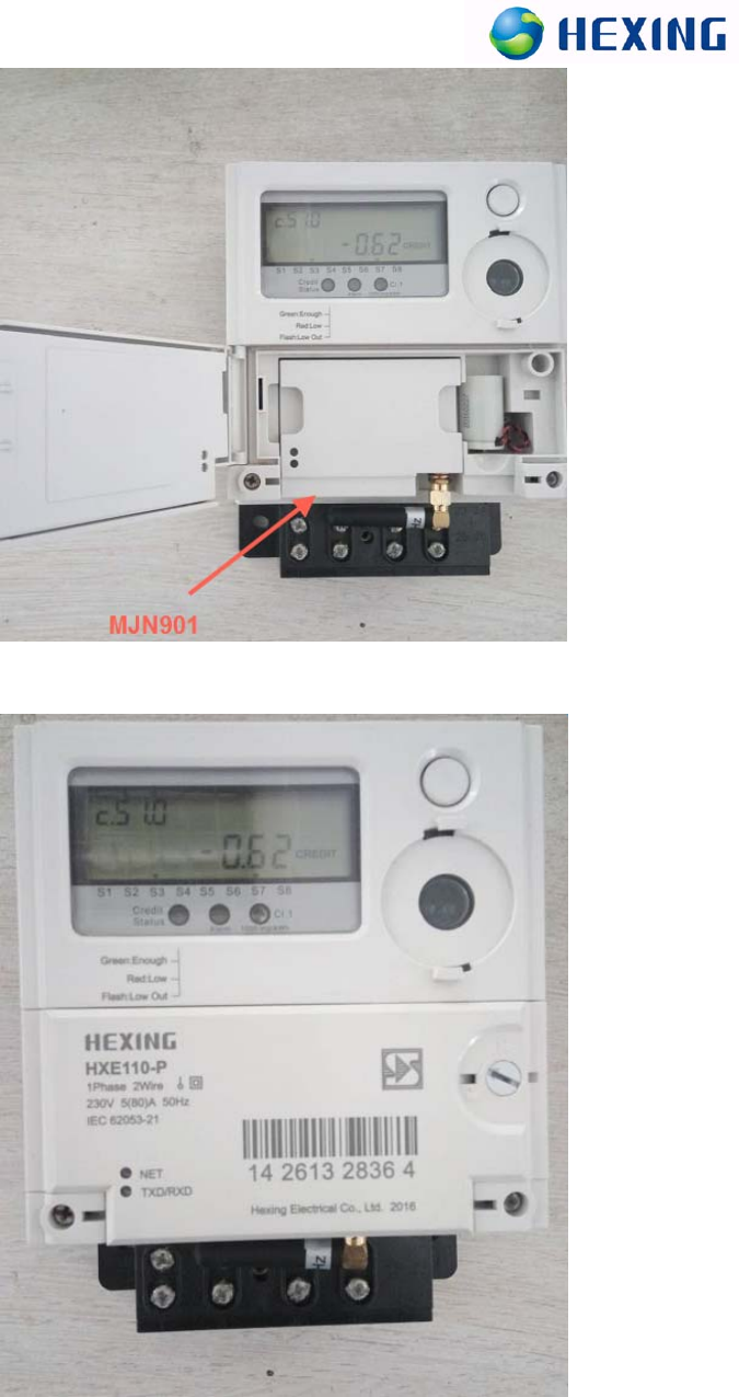
Installedinthesample
Installedinthesample
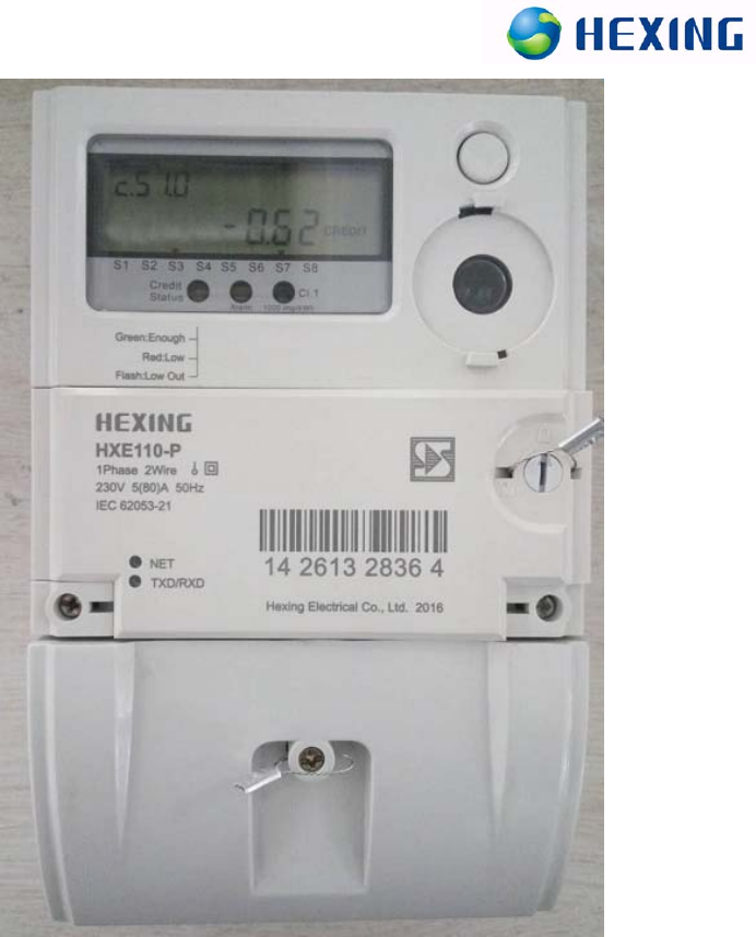
Installedinthesample
Electric meter models only for reference.
Note:
1 Thank you for using products of Hexing Electrical Co., Ltd. Please read this
warning before using our products. If you have already started to use is that you have
read and accept our all this.
2 All the final explanation and modification rights for all materials were reserved by
Hexing Electrical Co., Ltd.

FCC Warning:
Any Changes or modifications not expressly approved by the party responsible for
compliance could void the user's authority to operate the equipment.
This device complies with Part 15 of the FCC Rules. Operation is subject to the
following two conditions: (1) this device may not cause harmful interference, and (2)
this device must accept any interference received, including interference that may
cause undesired operation.
FCC Radiation Exposure Statement:
To satisfy FCC RF Exposure requirements for this transmission device, a
separation distance of 20cm or more should be maintained between the antenna of this
device and persons during operation. To ensure compliance, operation at closer than
this distance is not recommended. The antenna(s) used for this transmitter must not be
co-located or operating in conjunction with any other antenna or transmitter.