Hexing Electrical MJP900-A2 HexNet RF Module User Manual
Hexing Electrical Co.,Ltd HexNet RF Module Users Manual
Users Manual

HexNet
RF Module(MJP900-A2)
User Manual
Version Maker Date
V0.0.1 WangGang 2016.12.20
HexingElectricalCo.,Ltd.

〉〉〉HexNet RF Module
1.Product Introduction
The HexNet RF module is a highly integrated half-duplex micropower
wireless data transmission module.The HexNet RF module embedded
high-performance RF chip.User programming has very good flexibility.This
module provides multiple channels of choice, can modify band width, data
rate and other parameters.HexNet module operating frequency include
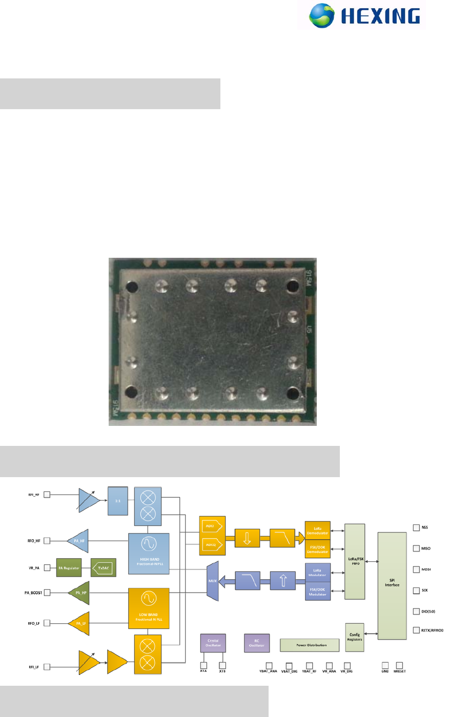
915MHZ. The real figure as shown in the figure below.
2.RF Module Chip Block Diagram
3.RF Module Pin Definition

1GNDGND
2GNDGND
3VCC_PAPAchippower
4GNDGND
5GNDGND
6GNDGND
7VCC_RFRFchippower
8RESETRESETPin
9DIO0RXDone、TXDone、CADDone
10DIO1FHSS
11DIO2/
12DIO3CADDetected,PLL_Lock
13DIO4/
14SCKSPIClock
15MISOSPIDataOut
16MOSISPIDataIn
17NSSSPISelectedPin
18GNDGND
19RFRFAntenna
4. 4-wire Serial Configuration and Data
Interface
HexNet is configured via a simple 4-wire SPI-compatible interface (MOSI, MISO,
SCLK, and NSS) where HexNet is the slave. This interface is also used to read and
write buffered data.
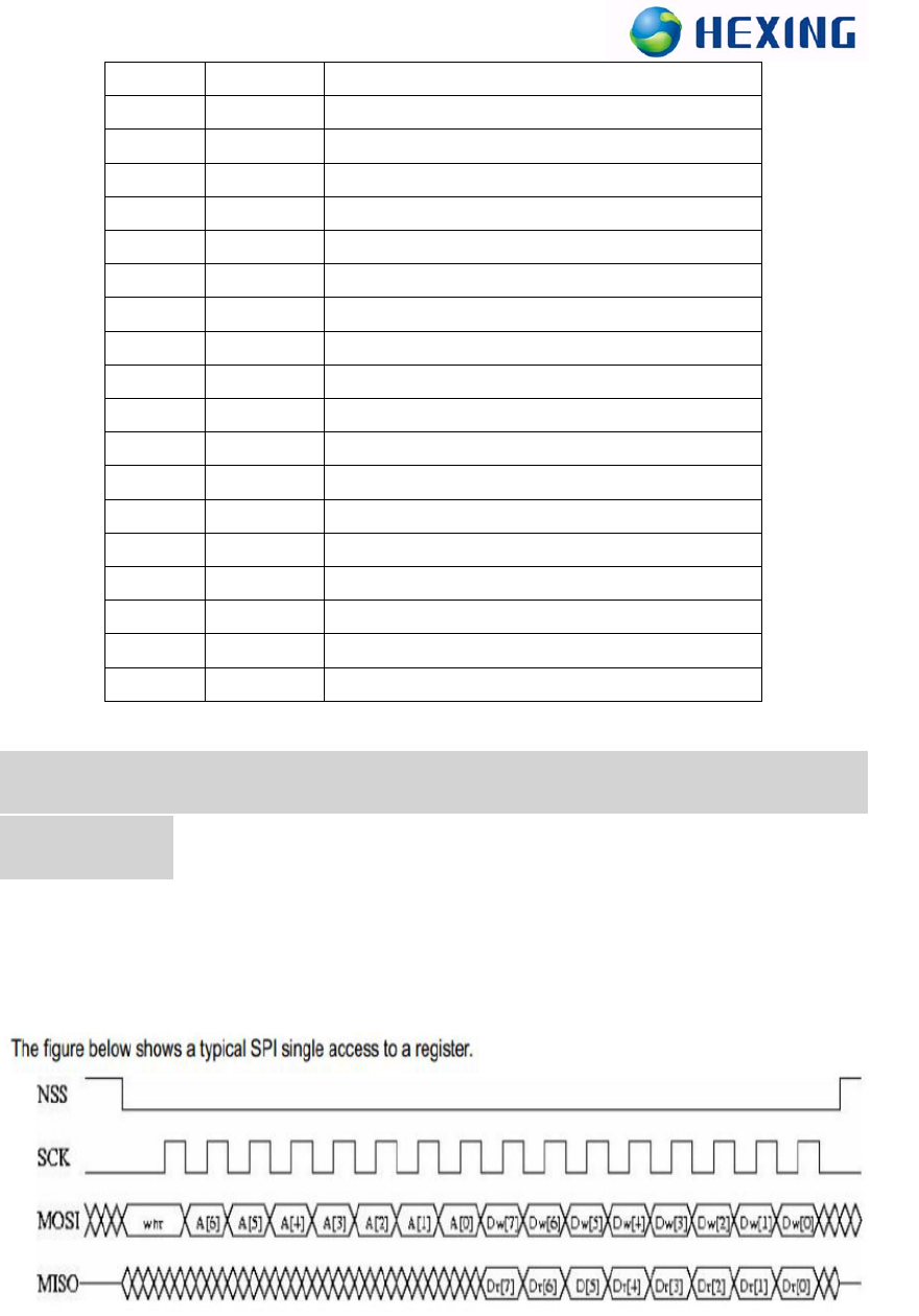
Figure 1 Configuration Registers Write and Read Operations
MOSI is generated by the master on the falling edge of SCK and is sampled by the
slave (i.e. this SPI interface) on the rising edge of SCK. MISO is generated by the
slave on the falling edge of SCK.

A transfer is always started by the NSS pin going low. MISO is high impedance when
NSS is high.
The first byte is the address byte. It is comprises:
A wnr bit, which is 1 for write access and 0 for read access.
Then 7 bits of address, MSB first.
The second byte is a data byte, either sent on MOSI by the master in case of a write
access or received by the master on MISO in case of read access. The data byte is
transmitted MSB first.
Proceeding bytes may be sent on MOSI (for write access) or received on MISO (for
read access) without a rising NSS edge and re-sending the address. In FIFO mode, if
the address was the FIFO address then the bytes will be written / read at the FIFO
address. In Burst mode, if the address was not the FIFO address, then it is
automatically incremented for each new byte received.
The frame ends when NSS goes high. The next frame must start with an address byte.
The SINGLE access mode is therefore a special case of FIFO / BURST mode with
only 1 data byte transferred.
During the write access, the byte transferred from the slave to the master on the MISO
line is the value of the written register before the write operation.
5. User operation
Insert the HexNet module on user’s printed circuit boards,use MCU SPI
SPI communication with the module.Control the RF register and FIFO to
complete wireless data transceiver functions.
This HexNet module is mainly used in power system, electricity information
collection system. Mainly include the following equipments: Data Concentrator, Data
Collector, Smart Electric Meter,etc.

Note:
1 Thank you for using products of Hexing Electrical Co., Ltd. Please read this
warning before using our products. If you have already started to use is that you have
read and accept our all this.
2 All the final explanation and modification rights for all materials were reserved by
Hexing Electrical Co., Ltd.
FCC Warning:
Any Changes or modifications not expressly approved by the party responsible for
compliance could void the user's authority to operate the equipment.
This device complies with Part 15 of the FCC Rules. Operation is subject to the
following two conditions: (1) this device may not cause harmful interference, and (2)
this device must accept any interference received, including interference that may
cause undesired operation.

The modular transmitter must be equipped with either a permanently affixed label or
must be capable of electronically displaying its FCC identification number:
If using a permanently affixed label, the modular transmitter must be labeled with its
own FCC identification number. and, if the FCC identification number is not visible
when the module is installed inside another device, then the outside of the device into
which the module is installed must also display a label referring to the enclosed module.
This exterior label can use wording such as the following: “Contains Transmitter Module
FCC ID:2AIUZ-MJP900-A2.” Any similar wording that expresses the same meaning
may be used. The Grantee may either provide such a label, an example of which must be
included in the application for equipment authorization, or, must provide adequate
instructions along with the module which explain this requirement. In the latter case, a
copy of these instructions must be included in the application for equipment
authorization.
FCC Radiation Exposure Statement:
To satisfy FCC RF Exposure requirements for this transmission devices, a separation
distance of 20cm or more should be maintained between the antenna of this device and
persons during operation. To ensure compliance, operation at closer than this distance is
not recommended. The antenna(s) used for this transmitter must not be co-located or
operating in conjunction with any other antenna or transmitter.