Hi G Tek IGAV143916 AVL READER User Manual TTMS installation guide 1 2
Hi-G-Tek Ltd AVL READER TTMS installation guide 1 2
Hi G Tek >
USERS MANUAL

Tanker Truck Monitoring System User’s Guide I
Wireless Monitoring Solutions for Security and Management
P/N: UM4718
Date: 31-AUG-06
Rev: 1.2
T
T
TT
T
TM
M
MS
S
S
Tanker Truck Monitoring System
I
I
In
n
ns
s
st
t
ta
a
al
l
ll
l
la
a
at
t
ti
i
io
o
on
n
n
a
a
an
n
nd
d
d
O
O
Op
p
pe
e
er
r
ra
a
at
t
ti
i
io
o
on
n
n
User’s Guide

Preface
About This Guide
Tanker Truck Monitoring System- User’s Guide II
A
Ab
bo
ou
ut
t
T
Th
hi
is
s
G
Gu
ui
id
de
e
This User Guide provides the information required to install and configure the hardware and
software required to run the Fleet application.
R
Re
ev
vi
is
si
io
on
n
H
Hi
is
st
to
or
ry
y
The revision history for this document is shown in Table
1-1.
Table
1-1: Revision history
Version Date Description
1.0 22-MAY-06 Initial
1.1 9-Aug-06
1.2 31-Aug-06

Preface
Warnings and Safety
Tanker Truck Monitoring System- User’s Guide III
W
Wa
ar
rn
ni
in
ng
gs
s
a
an
nd
d
S
Sa
af
fe
et
ty
y
ATTENTION
• The TTMS system is distributed to a commercial/industrial use only, and should only be handled by
personnel authorized by Hi-G-Tek representatives.
• Installation must be performed according to this User Guide.
• Using only certified antennas: It is the responsibility of the installer to ensure that when using the
outdoor antenna kits in the United States (or where FCC rules apply), only those antennas certified with
the product are used. The use of any antenna other than those certified with the product is expressly
forbidden in accordance with FCC rules CFR47 part 15.204.
The FCC Wants You to Know
This equipment has been tested and found to comply with the limits for a Class B digital device,
pursuant to Part 15 of the FCC rules. These limits are designed to provide reasonable protection
against harmful interference in a residential installation. This equipment generates, uses and can
radiate radio frequency energy and, if not installed and used in accordance with the instructions,
may cause harmful interference to radio communications. However, there is no guarantee that
interference will not occur in a particular installation. If this equipment does cause harmful
interference to radio or television reception, which can be determined by turning the equipment
off and on, the user is encouraged to try to correct the interference by one or more of the
following measures:
a) Reorient or relocate the receiving antenna.
b) Increase the separation between the equipment and receiver.
c) Connect the equipment to an outlet on a circuit different from that to which the
receiver is connected.
d) Consult the dealer or an experienced radio/TV technician.
FCC Warning
Modifications not expressly approved by the manufacturer could void the user
authority to operate the equipment under FCC Rules.
Instructions concerning human exposure to radio frequency
electromagnetic fields:
A distance of at least 20cm. between the equipment and all persons should be
maintained during the operation of the equipment.

Preface
Terminology
Tanker Truck Monitoring System- User’s Guide IV
T
Te
er
rm
mi
in
no
ol
lo
og
gy
y
Term Description
Seal DataSeal, or any other Hi-G-Tek sealing device.
AVL Reader DataReader which is connected to an AVL device.
HF Reader A DataReader that uses High Frequency long-range radio frequencies to communicate
with the DataSeals.
LF Reader A DataReader that uses Low Frequency short-range radio frequencies for communication
with the DataSeals. For example MicroReader, DataPort, Hand-Held Terminal.
SA Reader Stand Alone Reader with no direct connection to PC. Such a Reader does have
connection to a modem device (i.e. GPRS modem or DataRadio modem) which provides
communication to PC.
PC Personal Computer running the Data Collection program.

Preface
Table of Contents
Tanker Truck Monitoring System- User’s Guide V
T
Ta
ab
bl
le
e
o
of
f
C
Co
on
nt
te
en
nt
ts
s
About This Guide.......................................................................................................................... II
Revision History............................................................................................................................ II
Warnings and Safety ................................................................................................................... III
Terminology..................................................................................................................................IV
Table of Contents..........................................................................................................................V
Intr
oduction to the TTMS System
........................................................................................... 1
1.1 System Operation ........................................................................................................................3
1.2 Seals...........................................................................................................................................4
1.2.1.1 Seals for Valves......................................................................................................4
1.2.1.2 Seals for Hatches ...................................................................................................4
1.3 TTMS Reader...............................................................................................................................5
1.3.1 AVL Reader........................................................................................................................5
1.3.1.1 AVL Reader Ports and Indicators.............................................................................6
1.3.1.2 AVL Reader J1/J2 Molex Ports Pinout.......................................................................8
1.3.1.3 AVL Reader I/O Electrical Characteristics .................................................................9
1.3.1.4 AVL Reader Block Diagram......................................................................................9
1.3.2 AVL Antenna....................................................................................................................10
1.3.3 GPS Cellular Module..........................................................................................................10
1.3.4 Seal Status Indicator and Protection Box............................................................................11
1.3.4.1 Seal Status Indicator ............................................................................................11
1.3.4.2 Protection Box......................................................................................................13
1.4 Setup and Management Software ...............................................................................................14
1.4.1 Setup and Analysis SW .....................................................................................................14
1.4.2 Management SW Module ..................................................................................................14
1.4.3 SAP Driver .......................................................................................................................14
1.4.4 Hi-G-Tek OCX...................................................................................................................14
Initial System Setup................................................................................................................... 15
2.1 General.....................................................................................................................................15
2.2 Preliminary Setup.......................................................................................................................16

Preface
Table of Contents
Tanker Truck Monitoring System- User’s Guide VI
2.3 Grouping and Connecting the System Elements...........................................................................16
2.4 Configuring the Seals.................................................................................................................17
2.5 Configuring the Reader and Refineries ........................................................................................21
2.6 Defining the Truck Configuration ................................................................................................22
2.6.1 Configuring Application Parameters ...................................................................................25
2.6.2 Verifying the Seal Status Indicators Operability ..................................................................26
2.6.3 Verifying Communication between Reader and Seals..........................................................27
2.7 Configuring Coordinates of the Authorized Refineries...................................................................27
2.8 Fleet Management SW ...............................................................................................................30
2.8.1 Seal Configuration and Management..................................................................................31
2.8.2 Reader Configuration and Management .............................................................................31
2.8.3 Monitoring Events.............................................................................................................31
2.8.4 Event Notification Options.................................................................................................31
2.8.5 Report Generation Options................................................................................................31
Installation .................................................................................................................................. 32
3.1 Overview...................................................................................................................................32
3.1.1 Hardware Installation .......................................................................................................32
3.2 Seal Installation.........................................................................................................................33
3.2.1.1 Filling Hatches Installation ....................................................................................33
3.2.1.2 Draining Valves Installation...................................................................................34
3.3 Truck Cabin Installation-Preabmle...............................................................................................36
3.4 Truck Cabin Installation..............................................................................................................36
3.4.1 Preparing the Cabin..........................................................................................................39
3.4.2 Interconnecting the Units..................................................................................................39
Setup and Analysis.................................................................................................................... 39
4.1 Overview...................................................................................................................................39
4.1.1 Launching the Application.................................................................................................39
4.1.2 Defining Seal Ids..............................................................................................................39
4.1.3 Configuring Application Parameters ...................................................................................40
4.1.4 Verifying LED Display........................................................................................................41
4.1.5 Interrogating Seals...........................................................................................................42
4.1.6 Configuring Site Coordinates.............................................................................................43
4.2 Fleet Management SW ...............................................................................................................44
4.2.1 Seal Configuration and Management..................................................................................44
4.2.2 Reader Configuration and Management .............................................................................45
4.2.3 Monitoring Events.............................................................................................................45

Preface
Table of Contents
Tanker Truck Monitoring System- User’s Guide VII
4.2.4 Event Notification Options.................................................................................................45
4.2.5 Report Generation Options................................................................................................45
Technical Specifications........................................................................................................... 46
5.1 AVL Reader Technical Specifications............................................................................................46
5.2 Seal Status Indicator Specifications.............................................................................................48
5.3 Protection Unit……………………………………………………………………………………………………………………….49

Fleet Application User’s Guide 1
1
I
In
nt
tr
r
o
od
du
uc
ct
ti
io
on
n
t
to
o
t
th
he
e
T
TT
TM
MS
S
S
Sy
ys
st
te
em
m
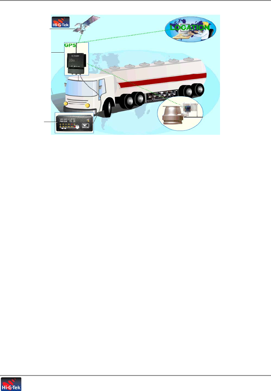
Hi-G-Tek’s Tanker Truck Monitoring System (TTMS) secures the tanker fueling hatches and
decanting valves and enables continuous real time remote monitoring of the vehicle at all points
on the route. Any unauthorized attempts to access the secured hatches or valves are recorded
on the seals and invoke real-time, detailed alarms at the Control Center.
The tanker access points are secured with programmed electronic seals. These are monitored by
a Reader installed in the truck cabin. The Reader reports, via GPRS or SMS, to the remote
control center of any unusual events along with clock and location information acquired through
GPS. The control center can also transmit commands or information to the seals via the Reader.
An LED display mounted inside the cabin provides visual indication of the status of each seal,
enabling the operator at the refinery to see, at a glance, whether an attempt has been made to
tamper with the vehicle hatches or valves – before authorizing the fueling procedure.
Introduction to the TTMS System
System Operation
Tanker Truck Monitoring System- User’s Guide 2
Figure 1-1.
Main features and capabilities
• Real time alerts transmitted to the control center through GPRS (in addition to SMS)
• GPS location tracking and clock
• Remote control and management of the system elements from the control center
• Areas of valid refinery and gas station areas are configured to prevent unauthorized
activities outside the defined sites
• System is configurable to support one or two tankers, where configuration can be easily
modified
• Independently runs routines to monitor the seals for unusual events defined according to
specific scenarios
• Battery backup mode ensures continuous operation and support of the essential features in
case the power supply from the vehicle is interrupted
• LED display provides a local visual indication of the status of the seals to the operator or
inspector
LED Seal Status
Indicator
AVL Reader
Hatch/Valve seal
Control Center
GPS
Communication
Introduction to the TTMS System
System Operation
Tanker Truck Monitoring System- User’s Guide 3
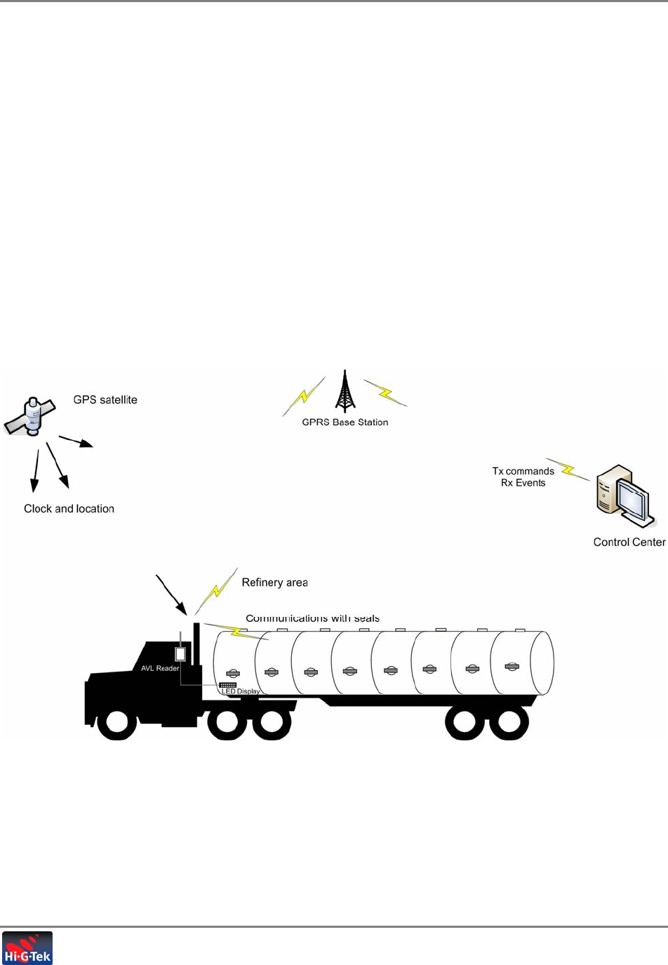
1.1 System Operation
The valve and cover of each section are protected by an electronic seal with sensors. The
seals are monitored by the Reader installed in the cabin. The seals record various events
(according to the configuration) and transmit notifications such as open/closed to the Reader
via HF.
The TTMS Reader forwards the events received from the seals to the Control Center via
cellular, along with location and time information received via GPS. In the other direction,
commands from the Control Center are forwarded by the Reader to the seals.
In addition, the Seal Status Display shows, at a glance, a summary of the status of each seal
as OK (GREEN) or tampered (RED).
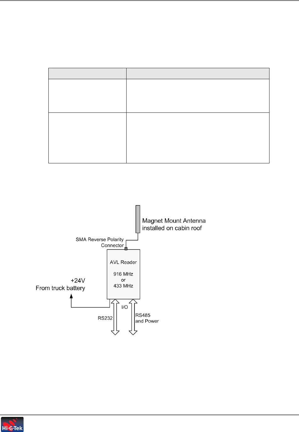
The following figure illustrates communication between the TTMS Reader and the other system
elements.
Introduction to the TTMS System
Seals
Tanker Truck Monitoring System- User’s Guide 4
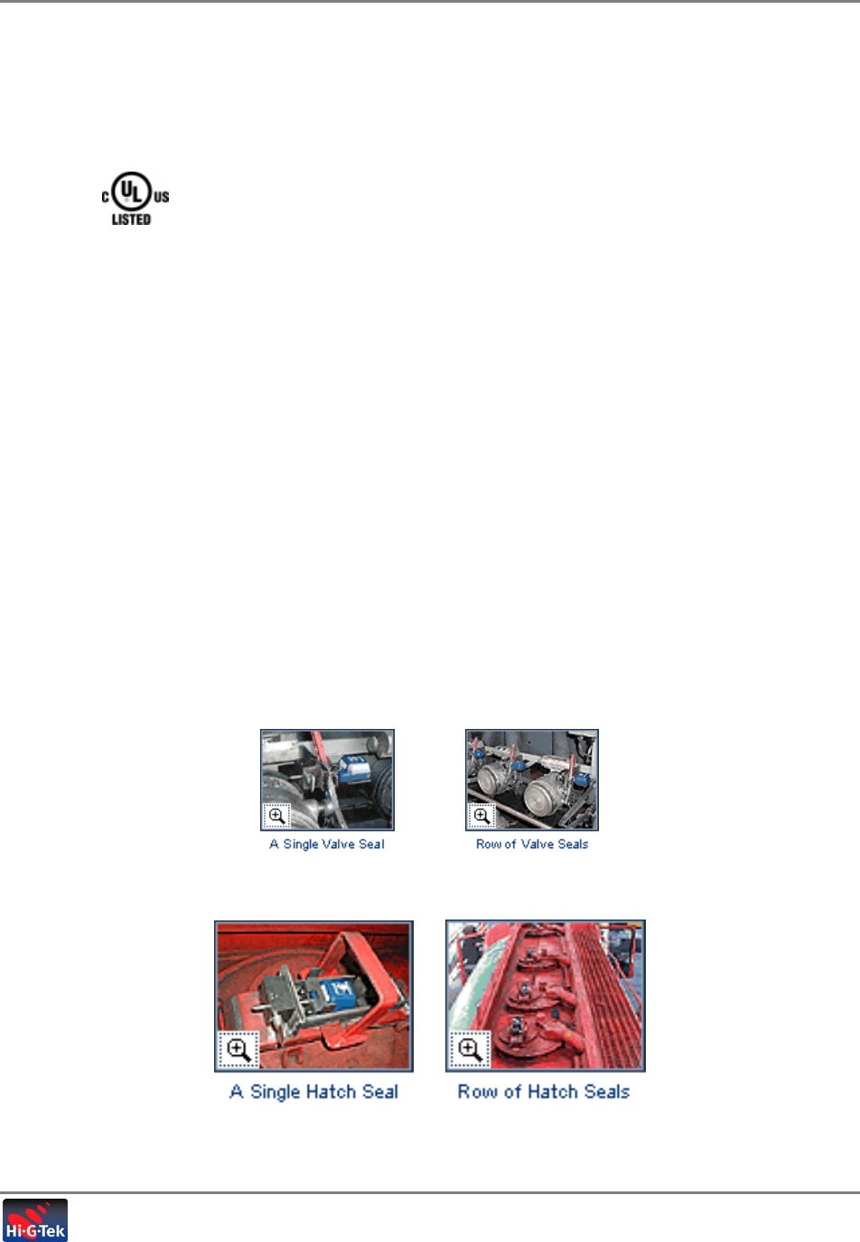
1.2 Seals
UL recognized for Intrinsic Safety - file number: E256795
The seals are portable, reusable electronic devices installed on each hatch and valve. The seals
perform the following functions:
• Physically secure the access point (hatch or valve)
• Monitor the access point through sensors and generate status information and alarms
corresponding to various programmed conditions
• Store user data for retrieval
Two types of seals are provided in the TTMS: hatch seals and valve seals. The seals differ in
the length of the locking pin and the mounting bracket.
1.2.1.1 Seals for Valves
There are two types of valve seals whose closing mechanism corresponds to different types of
valves:
• Valves that close through a circular CCW (up to 270°) turn of the handle
• Valves that close through a perpendicular pull of the handle – north to south
The following figures show seals assembled on valves with a ‘pull’ closing mechanism
1.2.1.2 Seals for Hatches

Introduction to the TTMS System
TTMS Reader
Tanker Truck Monitoring System- User’s Guide 5
1.3 TTMS Reader
The TTMS Reader performs the following functions:
• Monitors the seals
• Receives clock and location co-ordinates from GPS
• Transmits seal events to the Control Center, along with GPS coordinates
• Transfers seals status information to the Seal Status Display
• Forwards commands from the Control Center to the seals
The TTMS Reader consists of two interconnected modules installed inside the cabin, and the
corresponding antennas:
• AVL Reader module and corresponding antenna
• GPS and Cellular (i.e. GPRS/GSM) module and corresponding antennas - add on (off the
shelf unit (manufactured by STARCOM)
The AVL unit is described in detail in the following sub-section (information on the STARCOM
unit is supplied in the corresponding User Manual).
1.3.1 AVL Reader
NOTE: This section provides a general description of the AVL Reader, functions and connections.
For a full description of the AVL specifications, refer to
5.1
The AVL Reader uses active wireless technology to provide automatic processing and real-time
monitoring of cargos during transit. The reader powered from the truck power (24V) is installed
inside the truck's cabin, It has read/write capabilities for communicating with the cargo/tank
sensors simultaneously in order to verify their presence and status. The reader uses two RF
channels (LF, HF) for communication. It is equipped with back-up battery and supports two
RS232 channels in addition to one RS485 channel for communicating with other devices of the
Tanker Truck Monitoring System (TTMS).
As aforesaid the AVL Reader performs three major functions:
• Communicates (two-way) with and monitors the seals over a HF channel
• Transfers (two-way) information between the seals and the GPS/Cellular modem
• Provides seal status to the Seal Status Display
Communication with the seals
The AVL Reader communicates with the seals via a HF antenna that is installed externally on the
cabin roof – on the side of the valves on which seals are installed (usually passenger side). The
AVL Reader is powered via the vehicle’s battery.
Reader Setup
The AVL Reader is configured via a local connection between the Reader and a computer on
which the AVL Reader Config application is installed and launched.
Introduction to the TTMS System
TTMS Reader
Tanker Truck Monitoring System- User’s Guide 6
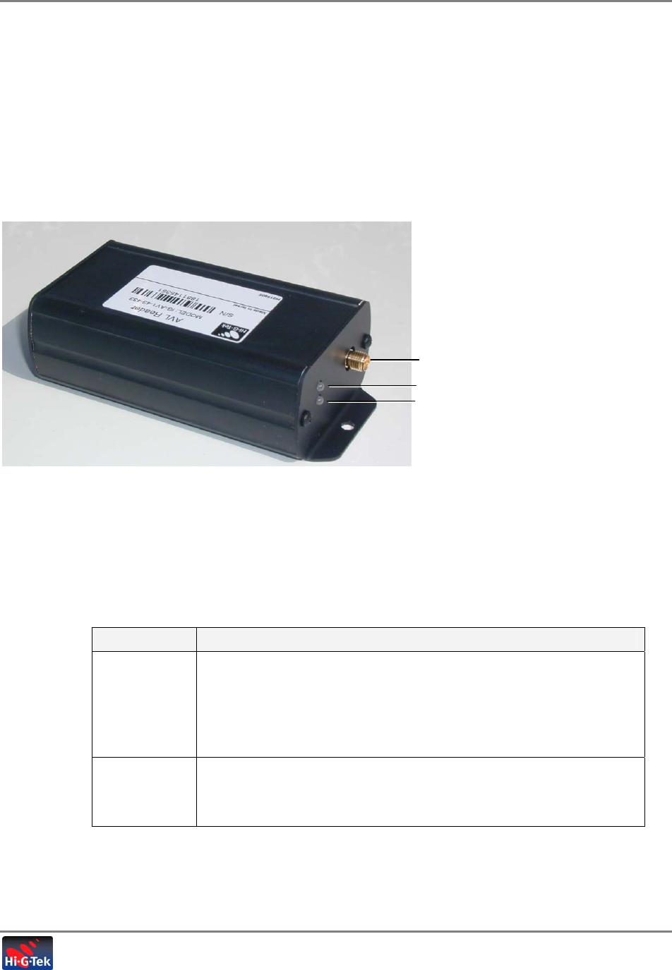
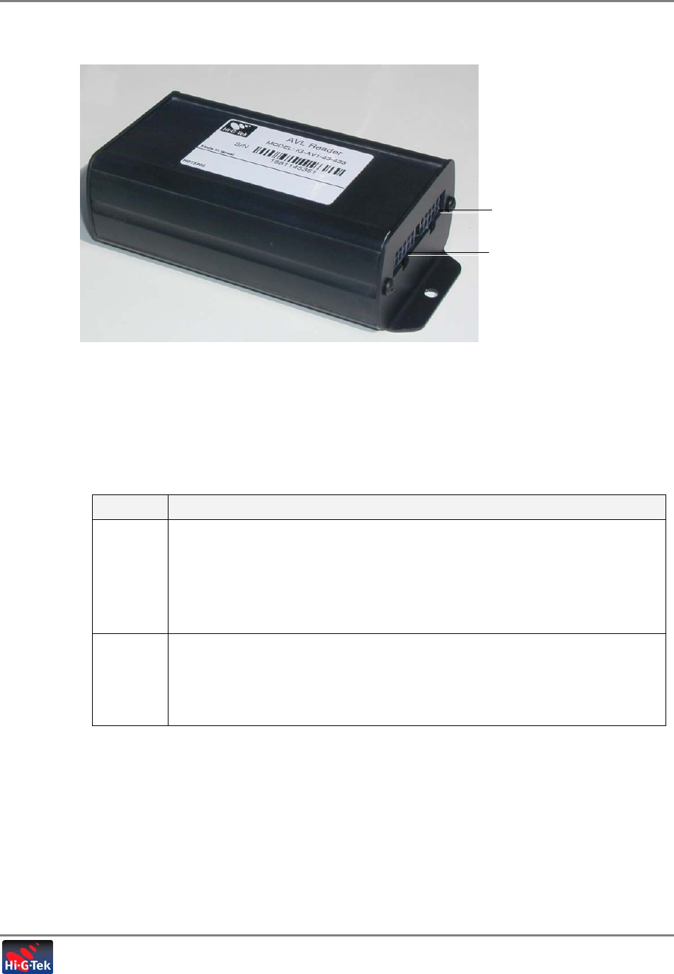
1.3.1.1 AVL Reader Ports and Indicators
The unit interfaces and connections are shown in the following figures:
• One side (Figure 1-2) contains the AVL antenna connections and LED indicators;
• The other side (Figure 1-3) provides the connections required for power, setup and interface
to the GPS/Cellular Modem.
The following figure shows the antenna connections and indicators.
Figure 1-2. AVL Reader Antenna Connection Side
AVL Antenna Port Description
Reverse polarity SMA connector (antenna specifications are given in section 1.3.2
LED Indicators
LED Description
Power Indicates power status and firmware download status (during firmware
upgrade).
o Power ON and self-test - color alternates between GREEN and
RED for several seconds: GREEN – OK, RED – fault
o Firmware download: Blinking during download process
COMM Communication:
• RED – unit is transmitting data
• GREEN – unit is receiving data
AVL Antenna connection
PWR indicator
COMM indicator
Introduction to the TTMS System
TTMS Reader
Tanker Truck Monitoring System- User’s Guide 7
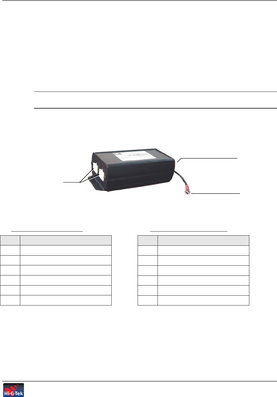
The following figure shows the AVL Reader Power & COM connector side.
Figure 1-3. AVL Reader Connector Interfaces
AVL Reader Molex Port Functions
The following table provides a description of the AVL ports.
Table
1-1. AVL Reader J1 J2 Port Function Descriptions
Port Description
J1 10 pin connector. Provides the following functions (see
Table
1-2
for pinout):
• RS232 connection to cellular modem.
• Power: +24V (from truck supply).
• One input auxiliary.
• One output auxiliary.
J2 12 pin connector. Provides the following functions (see
Table
1-3
for pinout):
• RS485 communication to Display Unit(s).
• Local RS232 Setup and Config connection to PC
• Auxiliary connections – three outputs, one input
J1
–
12 pin connector
J2 – 10 pin connector

Introduction to the TTMS System
TTMS Reader
Tanker Truck Monitoring System- User’s Guide 8
1.3.1.2 AVL Reader J1/J2 Pinout
Table
1-2. J1 Connector Pinout
Pin Signal
1 EXT Input
2 NC
3 EXT Output 3
4 -Vin (GND)
5 +Vin (+24VDC)
6 RS232 – TxD J45 to LCU
7 RS232 – RxD J45 to LCU
8 RS232 – COMM J45 to LCU
location command unit
9 NC
10 NC
Table
1-3. J2 Connector Pinout
Pin Signal
1 NC
2 EXT Output 1
3 NC
4 EXT Output 2
5 -Vin (GND)
6 +Vin (+24VDC)
7 RS485 A
8 RS485 B
9 RS485 COMM
10 RS232 – COMM
11 RS232 – TxD
12 RS232 – RxD
Introduction to the TTMS System
TTMS Reader
Tanker Truck Monitoring System- User’s Guide 9
1.3.1.3 AVL Reader I/O Electrical Characteristics
The following table provides the characteristics for the External Interrupt and Output.
Table
1-4. AVL Reader I/O Characteristics
I/O Type Description
External Interrupt Input Active Low
Max input voltage = ±30VDC
Max ViL = 1VDC
Output Open collector general purpose output
Current must be limited to 20mA typical, 50mA
max.
Voltage max = 30V
Max VOL at 50mA = 1V
1.3.1.4 AVL Reader Block Diagram
Introduction to the TTMS System
TTMS Reader
Tanker Truck Monitoring System- User’s Guide 10
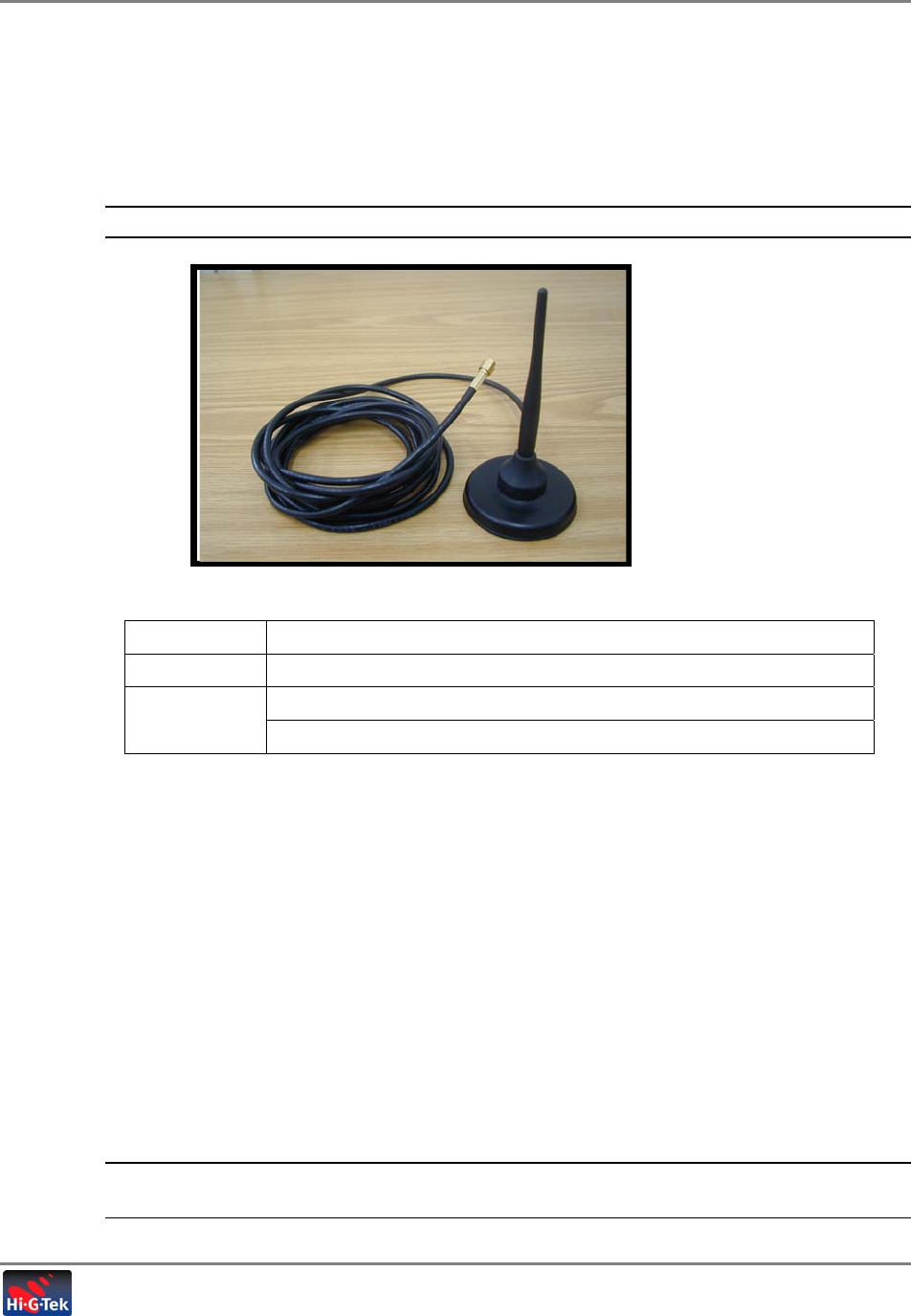
1.3.2 AVL Reader Antenna
A magnet mount type antenna is supplied with the system for use with the AVL Reader.
ATTENTION: Use only the antenna supplied with the system.
Figure 1-4 : AVL Reader- 916.5MHz Antenna ( corresponded to reverse polarity SMA connector)
Manufacturer Panorama Antennas
Type Magnet Mount Antenna
AS-U for 433.92MHz models Model No.
ASF-3061 for 916.5MHz models
1.3.3 GPS Cellular Module
The LCU500 manufactured by STARCOM is an Add on (off the shelf unit) in the TTMS. It integrates a GPS
receiver, a cellular network modem (GSM/GPRS/EDGE, CDMA/1X). The system monitors various vehicle
sensors, and provides the customer with a vast variety of real-time activities and information about the
vehicle.
The AVL Reader communicates with the LCU500 via RS-232 . From the moment the system is set, the
electronic sensors and AVL Reader begin to routinely communicate with the driver and control center,
reporting any activity involving the hatches, valves as well as the status of the truck, for complete monitoring
and security.
The GPS – Cellular Module (GPRS) performs the following functions:
• Continuously receives clock and location updates via GPS
• Transmits data between the AVL Reader and the Control Center, where data transmitted to
the Control Center is sent with the clock and location information.
REFER to the CORRESONDING - LCU500 DATA SHEET FOR COMPLETE
INFORMATION.
Introduction to the TTMS System
TTMS Reader
Tanker Truck Monitoring System- User’s Guide 11
1.3.4 Display Unit and Protection Unit
The Display unit is located inside the truck's cabin. It provides the operator a local visual
summary of the condition of the seals (tampered or OK). The TTMS system supports two Seal
Status Indicator boxes: one for each tank – according to the truck configuration. The Seal Status
Indicator interfaces to the TTMS System (specifically to the AVL Reader unit) through a
Protection Box.
Both units are described in the following sections.
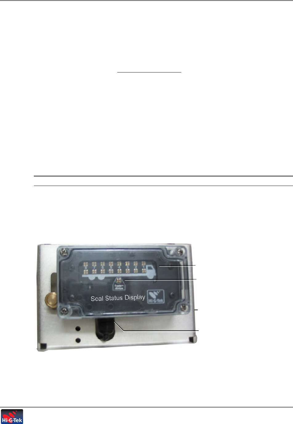
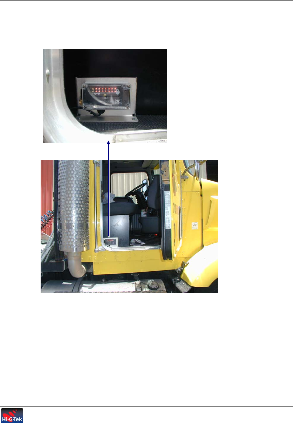
1.3.4.1 Seal Status Indicator
The seal status indicator unit provides status indication of the tamper conditions of all hatches
and valve seals. The unit is powered from protection unit (+12VDC regulated). It supports 16
LEDs that corresponding to each hatch or valve sensor of the tanker. Each Seal Status Indicator
unit communicates with the AVL Reader over RS-485 serial communication protocol.
NOTE: For trucks supporting two tanks, two units are installed.
Each Seal Status Indicator unit contains two rows of LED displays, corresponding to the hatches
and valves and a set of system LEDs providing general status information. The LEDs are lit RED
or GREEN according to the status of the seal ( Table 1-6).
Figure 1-5. Display Unit
LEDs corresponding to seals
installed on hatches/valves
General indicators
Bracket
RS485 port with cable

Introduction to the TTMS System
TTMS Reader
Tanker Truck Monitoring System- User’s Guide 12
Table 1-5. Display Unit Connector
Port Description
RS485 Connection to Protection Box
Table 1-6. Display Unit LED Status
LEDs Description
Individual Seal
LEDs GREEN - Seal closed, non-tampered conditions
RED Steady - Seal open, tampered condition
RED Blinking – Seal not detected by Reader
System Status RED – general fault indication
GREEN – normal operation
GREEN Blinking – system initialization in process
Table 1-7. J1 Connector Pinout
Pin Signal
1 -Vin (GND)
2 RS485 B
3 RS485 COMM
4 RS485 A
5 +Vin (+12VDC)
Introduction to the TTMS System
TTMS Reader
Tanker Truck Monitoring System- User’s Guide 13
1.3.4.2 Protection Unit
The Protection unit is located in the truck's cabin. It interfaces between the AVL Reader and the
Seal Status Indicator, filtering the AVL Reader signal and splitting it in installations with two Seal
Status Indicator units. (The Protection Box is transparent to the system.)
Interface to the AVL Reader and to each of the Seal Status Indicators is provided via RS485
communication. The output interface to the Seal Status Indicators include a +12V regulated
power line.
NOTE: The power and RS485 signals are delivered to Display unit via fuses and other protective
components in order to provide Over Current and Over Voltage protection.
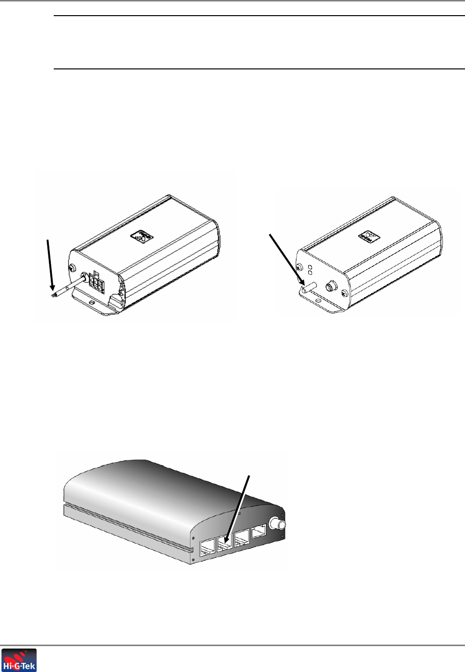
The Protection Box is shown in the following figure.
Figure 1-6. Protection Unit
Table 1-8. J1 Connector Pinout Table 1-9. J2/J3 Connector Pinout
Pin Signal
1 NC
2 RS485 COMM
3 -Vin (GND)
4 RS485 B
5 RS485 A
6 +Vin (+24VDC) EXT Input
Pin Signal
1 -Vout (GND)
2 RS485 COMM
3 NC
4 +Vout (+12VDC)
5 RS485 B
6 RS485 A
Connection to
AVL Reader
Connection to Seal
Status Indicators Groundin
g
Terminal

Introduction to the TTMS System
Setup and Management Software
Tanker Truck Monitoring System- User’s Guide 14
1.4 Setup and Management Software
Hi-G-Tek’s system is set up and configured through a local RS232 connection to the AVL Reader
from a computer (usually laptop) on which two setup application are installed:
• Seal Config SW – used to configure the group of seals to be installed on the truck
• AVL Config SW – used to configure the Reader and the authorized fueling sites
1.4.1 Setup and Analysis SW
The Setup and Analysis SW is used to configure the TTMS HW elements according to the
installation topology, to verify the responses of the devices after the installation and to
troubleshoot. The Setup and Analysis SW is an intuitive GUI application installed on a computer
(usually a laptop) that is connected to the TTSM Reader (AVL Reader module) through a local
(RS232) connection. Management SW Module
The Hi-G-Tek Management SW module provides management and monitoring options specific to
the Hi-G-Tek TTMS system elements. It is integrated into the user’s management application and
is accessed through a dedicated menu option.

Fleet Application User’s Guide 15
2
I
In
ni
it
ti
ia
al
l
S
Sy
ys
st
te
em
m
S
Se
et
tu
up
p
2.1 General
The first phase in the installation consists of verifying that the system elements are operational
and performing site configuration procedures such as configuring the system topology, defining
authorized refinery zones, etc. The Setup procedure is performed using the Configuration Tool
software application.
NOTE: It is recommended to perform the setup phase at the Hi-G-Tek distributor site or office.
If the zone definitions (coordinates and area) of the refineries are not available, they may be
physically mapped at each refinery according to the instructions in section 2.7.
This chapter provides step-by-step instructions on all the operations required at the initial phase.
It includes:
• Interconnecting the TTSM System elements;
• Connecting and launching the Configuration tool;
• Performing the basic setup and configuration procedures;
Initial System Setup
Preliminary Setup
Tanker Truck Monitoring System- User’s Guide 16
2.2 Preliminary Setup
The Setup procedure includes the following steps:
1. Grouping the system elements and performing the required interconnections.
2. Configure the seals using the Seal Config Application
3. Defining the Reader and authorized refineries
4. Configuring application parameters
5. Verifying that the LED Seal Status Indicators are operational
6. Interrogating the seals and verifying response
7. Configuring the Readers’ site coordinates
The steps above complete the installation procedure.
2.3 Grouping and Connecting the System Elements
Physically group the seals, TTMS Reader elements and LED Seal Status comprising a specific site
installation. Interconnect the TTMS Reader Elements and the LED Seal Status according to the
following figure.
Initial System Setup
Configuring the Seals
Tanker Truck Monitoring System- User’s Guide 17
2.4 Configuring the Seals
NOTE: Install the Seal Setup application on the computer from which the system will be
configured.
1. Connect a computer running the Seal Setup application to an AVL Reader through an RS232
cable.
NOTE: This does not necessarily have to be the AVL Reader installed on the truck.
Figure 2-1. RS232 Connection to AVL Reade
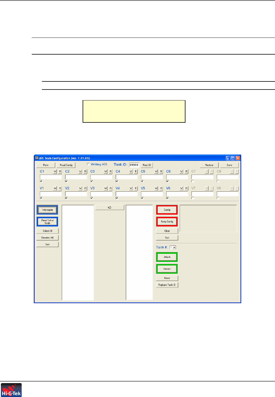
2. Launch the application Seal Setup application. The following window appears.
PICTURE OF AVL READER TO COMPUTER
CONNECTION
Initial System Setup
Configuring the Seals
Tanker Truck Monitoring System- User’s Guide 18
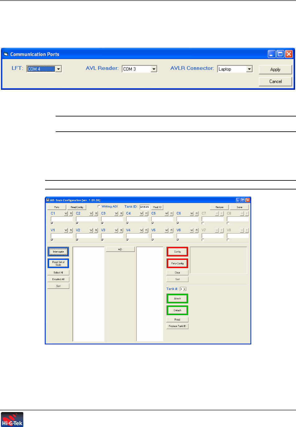
3. Define the communication parameters between the AVL Seal Config application and the AVL
Reader as follows:
• Click the Ports button. The following dialog appears.
• In the AVL Reader field, select the COMM port corresponding to the computer port to
which the AVL Reader is connected.
NOTE: The seals may also be configured using a DataPort. If a DataPort is connected, define the
LFT field.
• In the AVLR Connector field, select….
• Click Apply. The AVL Seal Config window is invoked.
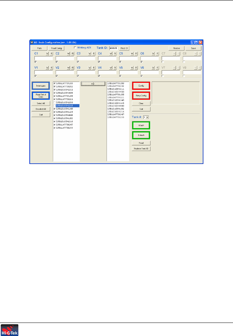
4. Clear the Screen by clicking the Clear button and then checkmark each relevant location
(C1, C2, C3, etc. for hatches and V1, V2, V3 for valve).
NOTE: Only the checkmarked location will be available for configuration.
Initial System Setup
Configuring the Seals
Tanker Truck Monitoring System- User’s Guide 19
5. Click Interrogate to read all the seals in the Reader’s zone. The detected seals are
displayed in the left column.
6. Select all the seals that will be installed on the truck (or click Select All and deselect the
irrelevant seals) and then click the Æ button. The relevant seals will be displayed in the right
column.
Initial System Setup
Configuring the Seals
Tanker Truck Monitoring System- User’s Guide 20
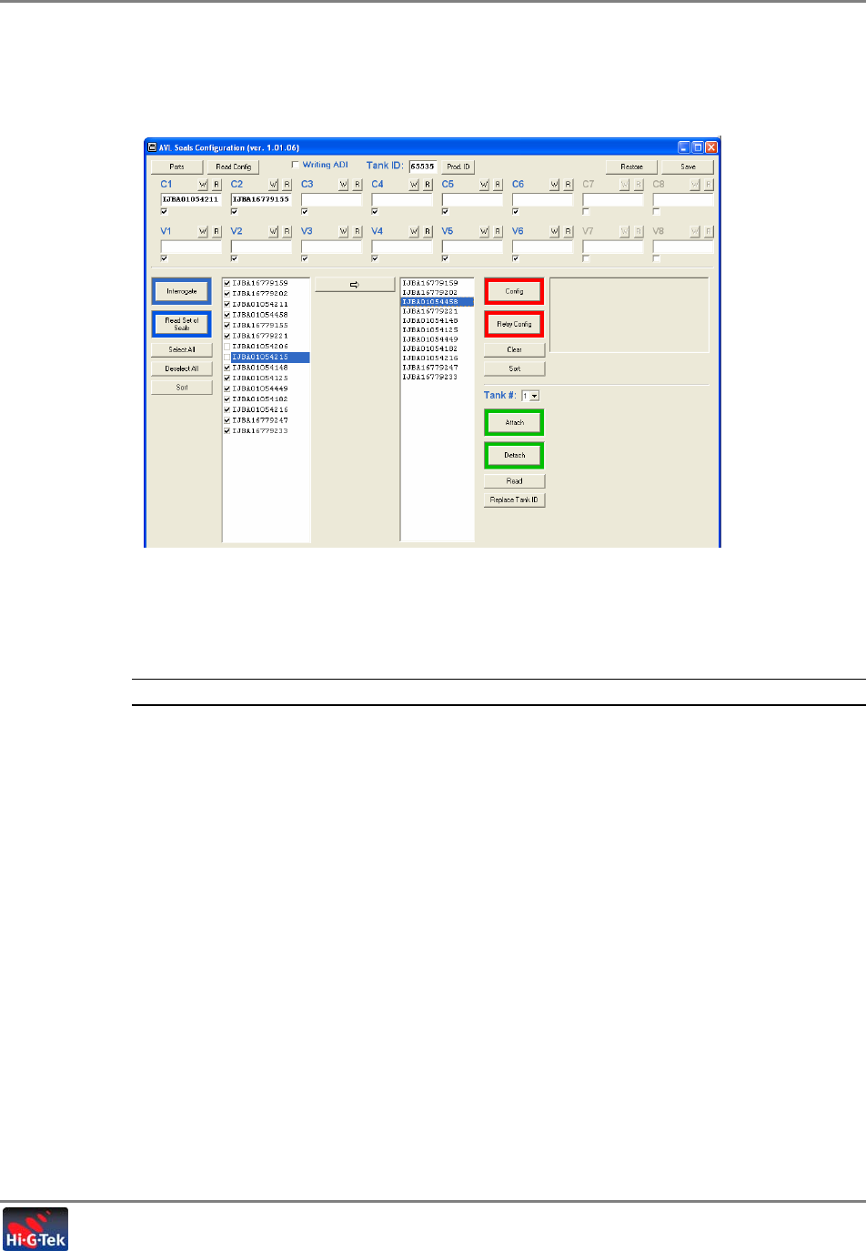
7. Click-and-drag each seal to one of the check marked locations corresponding to where that
seal will be installed on the truck (section and valve or hatch). Repeat until all seals have
been dragged to their destined locations.
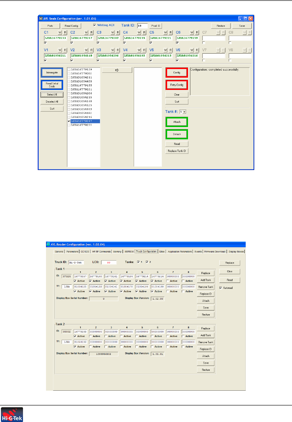
8. Click Config to record a map of all seals and their locations, in every seal in the installations.
As each seal is written, the corresponding message is displayed in the right window area. If
the configuration is successful, the message “Configuration Completed Successfully”
appears.
NOTE: You may have to repeat the command by clicking Retry Config.
Initial System Setup
Configuring the Reader and Refineries
Tanker Truck Monitoring System- User’s Guide 21
2.5 Configuring the Reader and Refineries

Initial System Setup
Defining the Truck Configuration
Tanker Truck Monitoring System- User’s Guide 22
e dialog includes the following tabs:
Tab Description
General
Parameters
CC1020
HF RF Commands
Memory
EEPROM
Truck Configuration Required for configuration.
Used to configure system elements for a specific truck. See section 2.6
Sites
Application
Parameters
Events
Firmware Download
Display Boxes
2.6 Defining the Truck Configuration
This tab is used to configure the system elements for a specific tank truck. This includes the
following:
• Number of tanks supported by the truck - one or two tanks
• ID of the seals to be installed on each tank – according to their compartment and location
• ID of the AVL Reader and AVL Units
• Seal Status Indicator
• Additional information
This procedure enables the elements to communicate with each other and allows identification at
the Control Center.
This tab is also used to update the configuration when changes are made in the system. For
example, seals are removed or replaced, tanks are added or removed (to trucks where this is
relevant), etc.
Initial System Setup
Defining the Truck Configuration
Tanker Truck Monitoring System- User’s Guide 23
To define the truck configuration
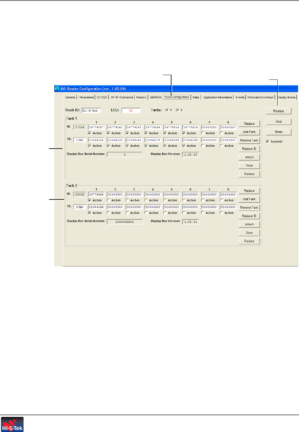
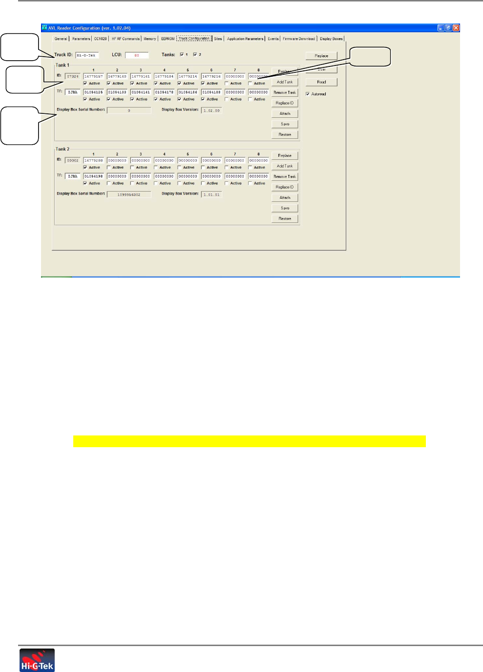
1. In the AVL Configuration window, click the Truck Configuration tab. The following
window appears.
Figure 2-2. Truck Configuration Window
The tab is divided into three main areas:
• General – used to define the general information on the truck
• Tank-1 and Tank-2 areas - each including the corresponding seals and Seal Status
Indicator information, configuration and updating options.
Truck Configuration tab
Definitions for
Tank 1
Definitions for
Tank 2
Tab editing options
Initial System Setup
Defining the Truck Configuration
Tanker Truck Monitoring System- User’s Guide 24
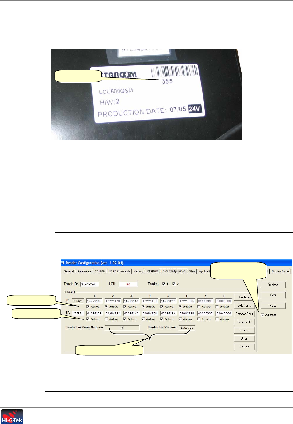
2. In the general area, define the following fields:
• Truck ID - enter the truck identification. This is usually the
license plate.
• LCU – enter the ID on the LCU label (i.e 365 as illustrated below)
Figure 2-3. Example of LCU Identification Label
• Tanks – check the tanks associated with the current truck (1/2). This will enable either
one or both configuration areas.
3. Configure the seal IDs according to their location, for Tank-1 and Tank-2 (if relevant):
• Verify that the Active box is check for every valve and hatch where a seal is installed.
• Verify that the Autoread option is checked. This causes the Reader to periodically read
the seal IDs and update the data
NOTE: To read once, disable Autoread and click the Read button. To Clear all the data, click
Clear.
The following figure shows the General (Truck ID, LCU, etc.) and Tank-1 option. (The
options for Tank-2 are identical to those of Tank-1.)
Figure 2-4. Partial Tab Showing Tank-1 and Editing Options
NOTE: The Seal Status Indicator serial number and version are updated automatically upon enabling
Autoread or clicking Read.
e.
g
. of LCU ID
Check to interro
g
ate
seals automatically
Active hatch seals
Active valve seals
Seal Status Indicator
if ti
Initial System Setup
Defining the Truck Configuration
Tanker Truck Monitoring System- User’s Guide 25
4. Click Replace to update the Reader with the new information or changes.
5. Click the Read button and the Reader ID and the Seal Status Indicator Serial Number will
appear in their respective fields.
6. To complete the configuration, click the Attach button to transfer all setup information to
Reader.
Taking truck (and trailer) out to an uncovered area where GPS access can be tested.
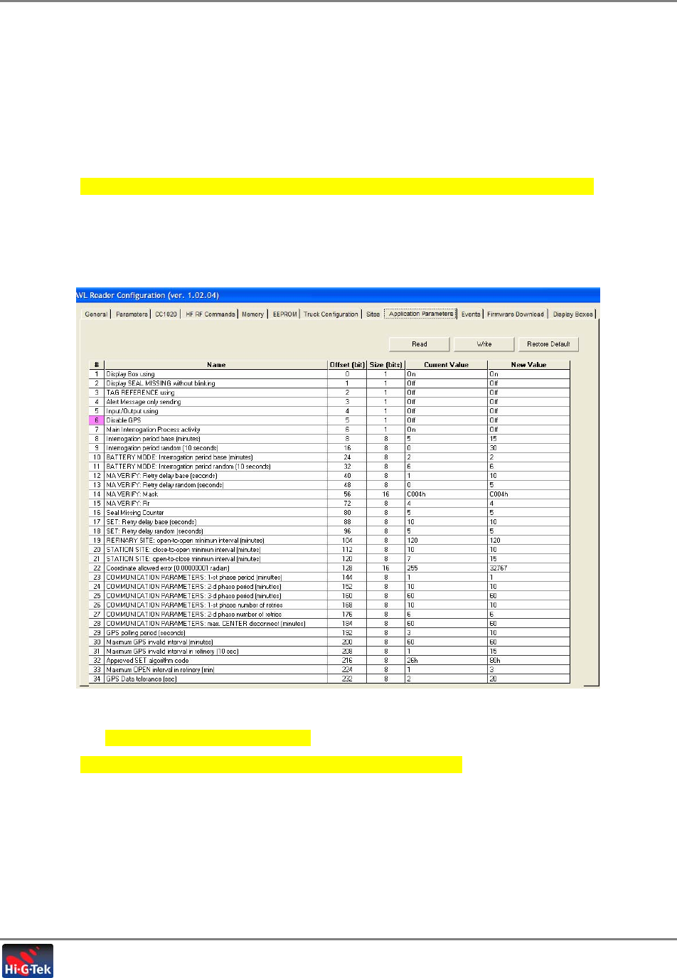
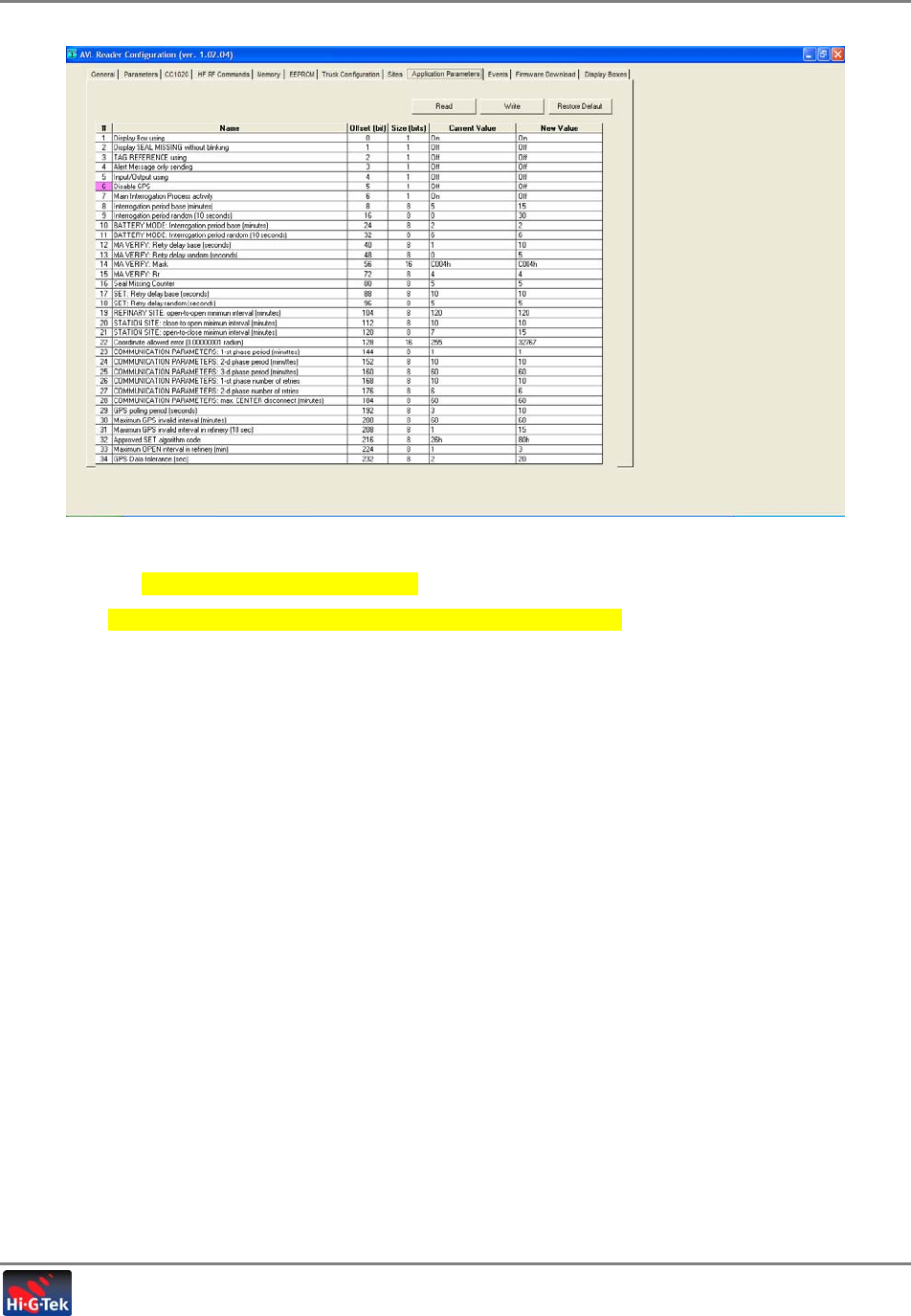
2.6.1 Configuring Application Parameters
1. Click Application Parameters tab in menu toolbar. The following window appears.
Figure 2-5. Application Parameters Tab
2. Adjust the application parameters.
Verify that the AVL unit ID numbers are recorded in the server.
Initial System Setup
Defining the Truck Configuration
Tanker Truck Monitoring System- User’s Guide 26
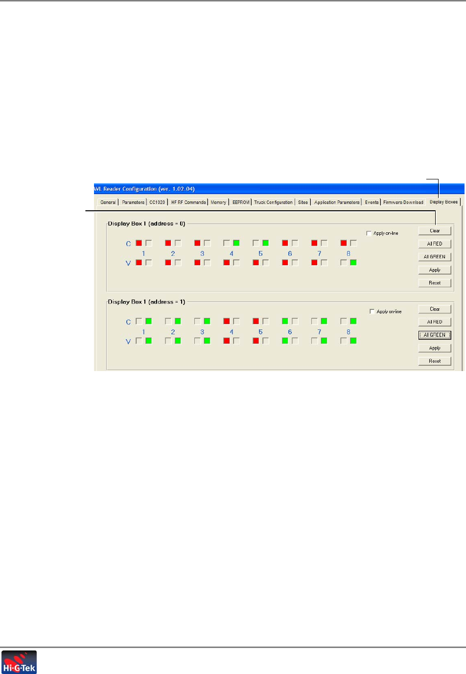
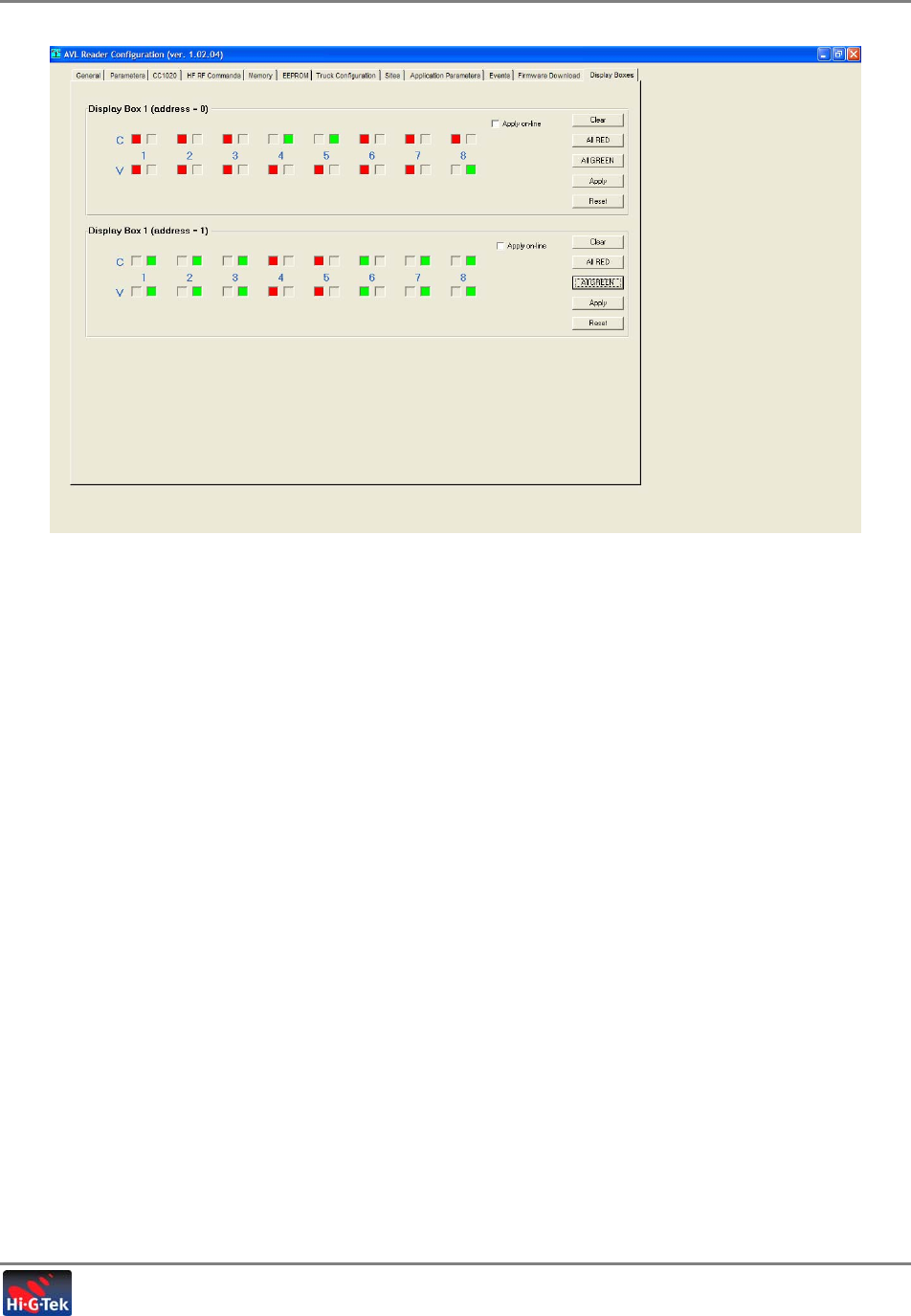
2.6.2 Verifying the Seal Status Indicators Operability
The Seal Status Indicators tab is used to view and test the operability of the Seal Status
Indicators. It contains buttons for testing the Seal Status Indicator LEDs by setting them to
Green, Red, Off, etc. and shows the status of each LED.
To verify and test Seal Status Indicator operability
1. In the AVL Configuration window, click the Seal Status Indicators tab. The following
window appears.
Figure 2-6. Seal Status Indicators Tab
The tab is divided into two areas, one for each Seal Status Indicator. Each area contains
LEDs that mirror the status of the corresponding Seal Status Indicator LEDs, and buttons for
testing the Seal Status Indicator LED responses.
LED Color Indications:
• Green – seal closed
• Red – seal open
• Off – seal not enabled
2. Begin by verifying that the display is operational for each Seal Status Indicator:
• Click All Green and Apply. All the corresponding LEDs should be Green.
• Click All Red and Apply. All the corresponding LEDs should be Red.
3. You toggle individual LEDs between Red, Green and flickering by repeatedly clicking on the
checkbox of the seal representation.
Seal Status
Indicators tab
Command buttons

Initial System Setup
Configuring Coordinates of the Authorized Refineries
Tanker Truck Monitoring System- User’s Guide 27
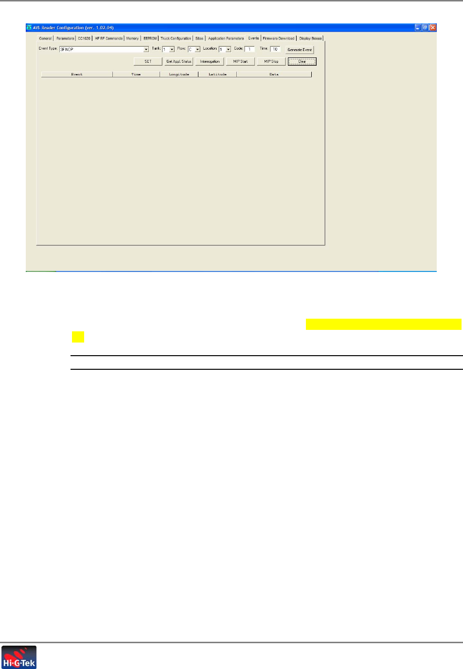
2.6.3 Verifying Communication between Reader and Seals
The Events tab is used to verify the communication between the Reader and the seals by
interrogating the seals, invoking events which are sent from the seal to the Reader and through
to the AVL Reader application where they are displayed.
To interrogate the seals
1. Click the Events tab from the menu toolbar. The following window appears.
Figure 2-7. Events Tab
2. Click the MIP Start button. A list of allocated seals, identified by the Reader, is shown.
3. Click Interrogation button to execute command and verify that all ‘attach’ commands are
OK.
NOTE: If there is no response, perform another interrogation.
4. Click Get Application Status and view response prompt – GPS OK, battery, etc.
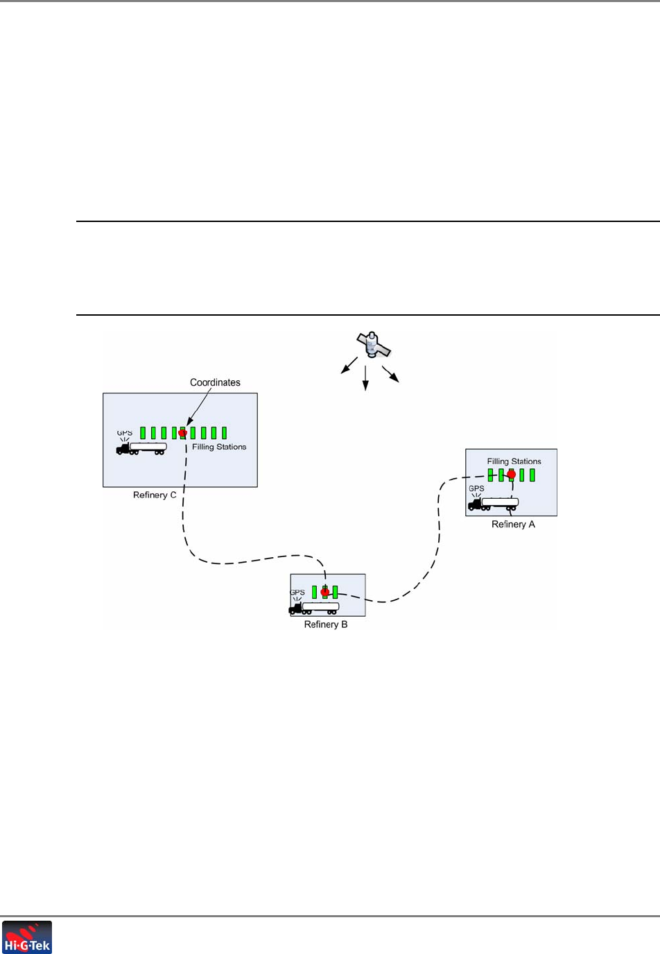
2.7 Configuring Coordinates of the Authorized Refineries
Configure the coordinates of every refinery site where the tanker truck, on which this system
will be installed, will be authorized to fill up. Seals can only be armed (SET command) at these
locations.
Initial System Setup
Configuring Coordinates of the Authorized Refineries
Tanker Truck Monitoring System- User’s Guide 28
The coordinates must be configured along with the radius of each refinery where the truck may
stop. The coordinates are configured according to the following criteria:
• The radius is square shaped
• Minimum radius – 30 meters
• Allowed GPS deviation – approximately 2 meters
• The number of filling stations at the refinery
• The distance of the filling stations from the edge of the refinery or the road
NOTE: One method of taking measurements is sending a tanker truck on which the seals are
installed, opening and closing the seals at each refinery location and analyzing the events
indicating the location at the Control Center. If this method is used, it is recommended to
perform the procedures at each refinery a number of times and take an average of the exact
location.
Figure 2-8.
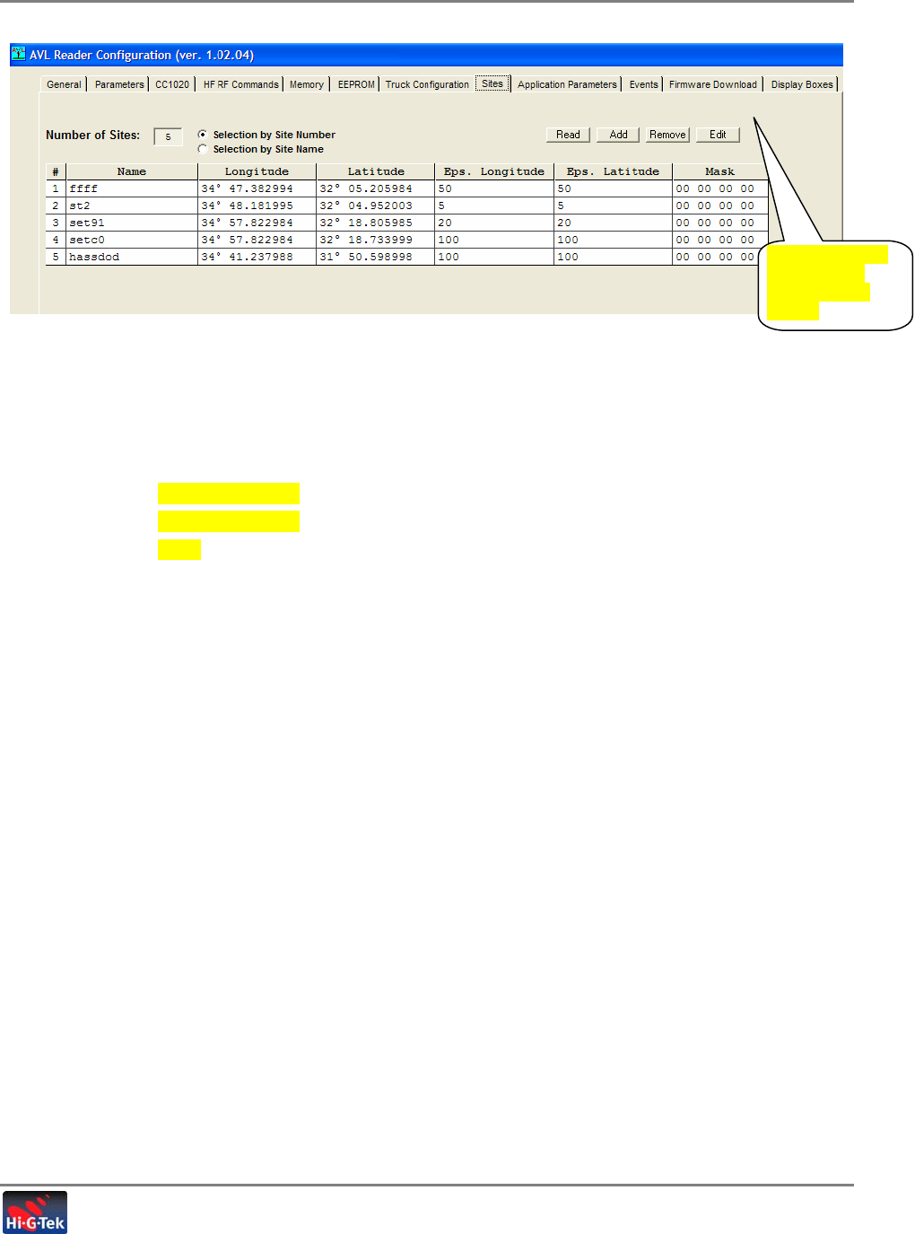
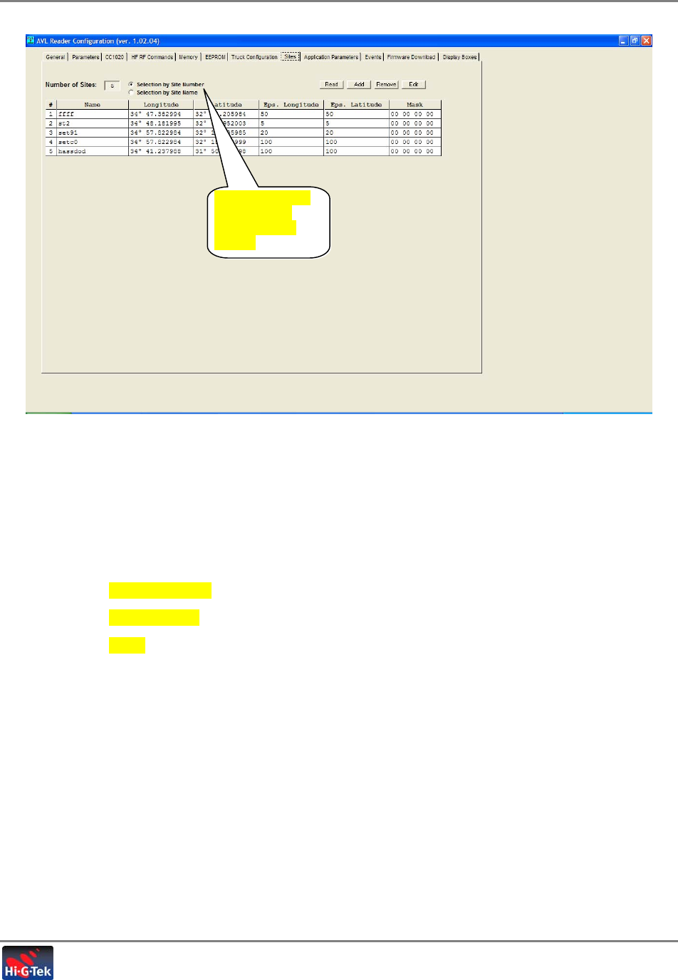
To define the coordinates
1. In the AVL Reader Configuration window, click the Sites tab. The following window appears.
Initial System Setup
Configuring Coordinates of the Authorized Refineries
Tanker Truck Monitoring System- User’s Guide 29
Figure 2-9. Sites Tab
2. Click Add and define the coordinates of each site (row) as follows:
• Enter the site Name.
• Enter the Longitude coordinates.
• Enter the Latitude coordinates.
• Eps. Longitude
• Eps. Latitude
• Mask
Are these options
relevant when
clicking “Read”
button?

Fleet Application User’s Guide 30
2.8 Fleet Management SW
• Verify (using the Fleet Management SW) that the command (Get Status) of the unit
invokes the appropriate response. (i.e. location). If OK, means there is com with the server
in both directions.
• Make sure all seals are closed. And then perform SET.
• Verify that all LEDs are green.
• Open each of the seals, hatches and valves. Verify that the correct status is received at the
fleet application.

Initial System Setup
Fleet Management SW
Tanker Truck Monitoring System- User’s Guide 31
2.8.1 Seal Configuration and Management
• Defining seal parameter thresholds
• Writing and reading seal’s electronic manifest such as cargo type, source, destination,
etc.
• Viewing seal status
• Viewing events stored on seals
• Sending commands to seals – Set, Read Events, etc.
2.8.2 Reader Configuration and Management
• Configuring Readers to forward interrogation (Verify) responses and seal initiated events
(Bursts) from specific seals in order to optimize operation
• Configuring Verify command (interrogation) parameters per Reader to optimize operation
in specific zones
2.8.3 Monitoring Events
• Burst and Verify events
• Real-time display of seal events such as opening of locks, tampering, motion, etc.
• Each event is displayed with detailed information fields such as event source, generation
time, Reader ID, etc.
• Filtering displayed information according to user defined criteria
2.8.4 Event Notification Options
Users can be notified of events through a variety of methods:
• SMS, E-mail and Voice messages to defined destinations
• Sound or visual on-screen alarms
2.8.5 Report Generation Options
Users can generate reports based on received events by filtering the received events according
to various user defined criteria such as date, event type, source, Reader ID, etc.
The selected events can then be saved as a *.TXT file.

Fleet Application User’s Guide 32
3
I
In
ns
st
ta
al
ll
la
at
ti
io
on
n
ATTENTION: Installation should be performed by authorized personnel and according to the
necessary safety precautions.
3.1 Overview
1. If the system was not checked on site, verify that the elements are operational by following
the procedures described in section TBD.
2. Install the seals on the hatches and valves.
3. Verify the operation of each seal – after the installation.
4. Fill the installation form with the serial number of every element in the system.
5. Install the cabin elements.
6. Check the installation again.
3.1.1 Hardware Installation
The hardware installation consists of the following main phases:
1. Seal installation: upper filling hatches and lower draining valves

Installation
Seal Installation
Tanker Truck Monitoring System- User’s Guide 33
1. Verifying responses of all seals.
2. Planning the location of the communication units (Reader, LCU 500, antennas, etc.), in the
truck cabin.
3. Seal Status Indicator placement.
4. Layout and routing of cables.
5. For fiberglass cabins only – installation of metal bracket for antenna
6. Placement of AVL Reader, LCU 500, Protection Unit and cable connections
7. Verifying system installation
3.2 Seal Installation
3.2.1.1 Filling Hatches Installation
1. Remove all previous installations (handles, chains, etc.)
2. Place the Locking unit and the seal housing on the two opening plates so that the locking
unit is located on the upper plate and the installation tool - while still in the seal housing - is
located on the lower plate.
3. Move the Locking unit knob towards the installation tool (refer to Figure 3-1).
NOTE: Make sure the installation tool is touching the side of the upper plate and is adjacent to it
Figure 3-1. Locking and Seal Housing Units
4. Weld small footholds to the locking unit and the seal housing without damaging the
installation tool.
5. Remove the installation tool and weld the locking unit and the seal housing.
6. After the units cool off, use the micro-reader to verify that the seal is functional; temporarily
install the seal as illustrated in Figure 3-2 and perform a reading.
Lockin
g
Unit
Installation
Seal Installation
Tanker Truck Monitoring System- User’s Guide 34
NOTE: The LED should be green when the locking unit is closed, and red when it is opened.
Figure 3-2. Temporary Installed Seal
7. Remove the seal until the installation is complete.
8. Weld a handle to the upper opening plate in a manner that will not hamper the functionality
of the locking unit.
9. Paint the welded areas with appropriate paint.
10. Install the seal inside the seal-housing, fasten the screws, and secure the screw with
appropriate thread locking adhesive (refer to Figure 3-2).
The following figure shows an example of a completed hatch installation.
Figure 3-3. Example of Completed Hatch Installation
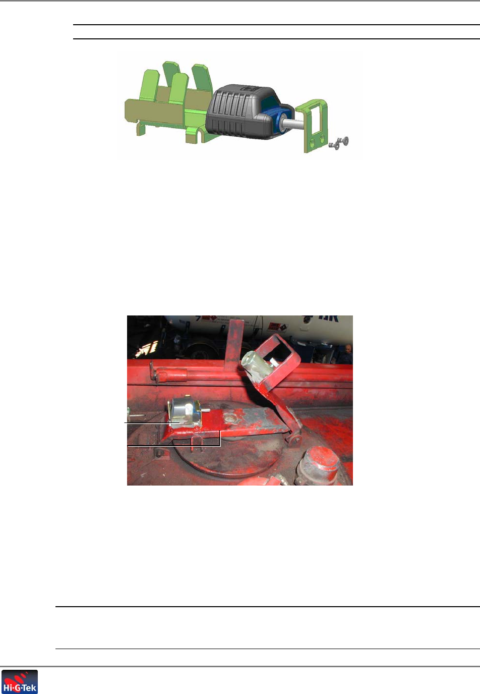
3.2.1.2 Draining Valves Installation
1. All devices which were used to lock the handle of the draining valves should be removed.
2. Fasten the device to its location by welding its backside (refer to Figure 3-4).
NOTE: The location of the device should not constrain the movement of the handle and should
allow the pin of the seal to go through the hole in the handle. If needed, add rulers to which the
device could be fastened.
Housin
g
Unit
Lower openin
g
plate
Installation
Seal Installation
Tanker Truck Monitoring System- User’s Guide 35
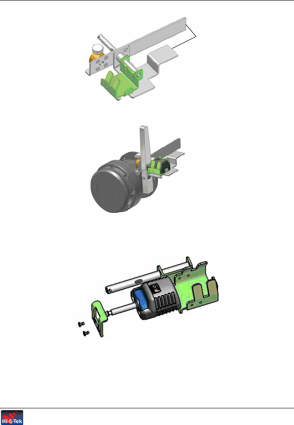
Figure 3-4. Draining Valve Locking Unit
Figure 3-5. Valve and Locking Unit
3. Install the seal inside the seal-housing, fasten the screws, and secure the screw with
appropriate thread locking adhesive (refer to Figure 3-6).
Figure 3-6. Installing the seal inside the housing
4. Paint the welded areas with appropriate paint.
Weldin
g
Areas
Installation
Preface -Truck cabin Installation .
Tanker Truck Monitoring System- User’s Guide 36
3.3 Preface -Truck cabin Installation .
NOTE: Installation should be performed by a certified car electrician and according to all
applicable standards.
3.3.1 Preparing the Cabin
Begin by unscrewing the dashboard covers on the passenger half and laying it bare in order
to locate the place in the dashboard that contains the least number of wires and
connections. This is usually on the side of the passenger, since on the driver’s side, all the
clocks and sensors are located.
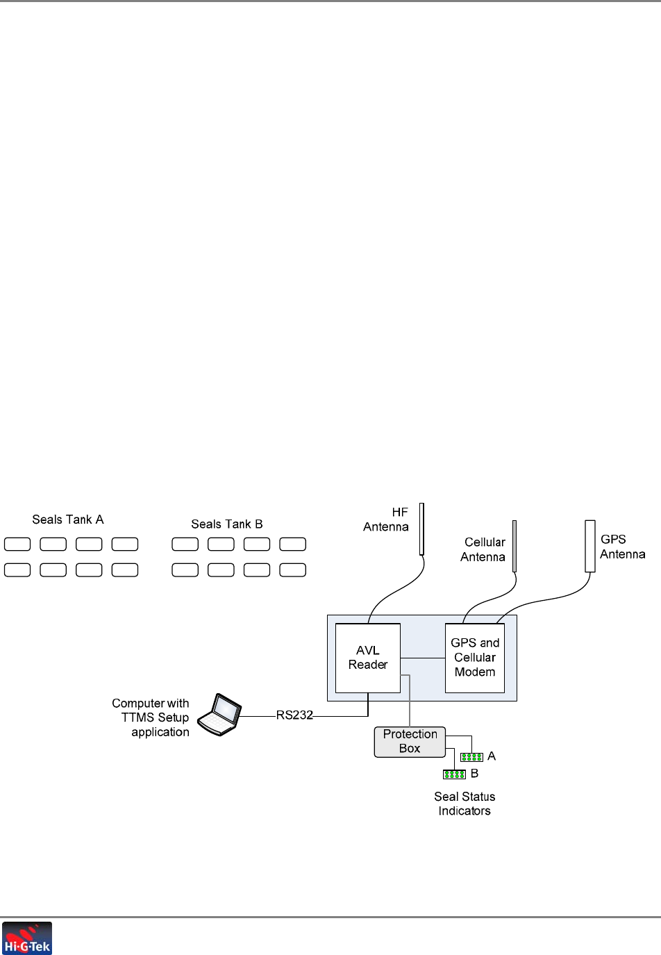
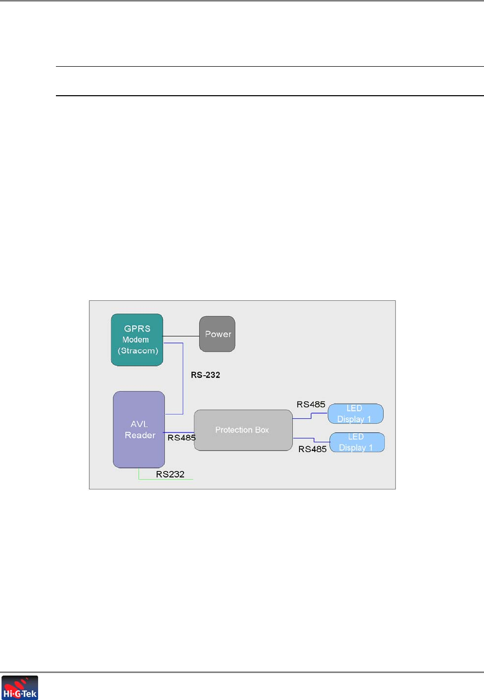
3.3.2 Interconnecting the Units
Figure 3-7. TTMS Architecture
3.4 Truck Cabin Installation
The installation procedure in the cabin consists installing the electronic units: AVL Reader, AVL
Unit (GPRS Modem), and external antenna with a magnetic base (connected to the AVL Reader),
GSM Antenna, Protection unit and LED Display unit.
1. Open the Dashboard.
2. Place and install AVL Reader and Protection unit in upper front storage compartment
(dashboard).
Installation
Truck Cabin Installation
Tanker Truck Monitoring System- User’s Guide 37
NOTE: The AVL Reader unit are fed from the vehicle supply. The supply should be connected
through a 2A fuse before the ignition switch; Use only provided Fuse + Fuseholder !
3. Power & Grounding connections:
• Connect the power lines (J1) via the in-line fuse (2A) to the vehicle supply (24VDC).
• Connect between AVL reader- J2/12pin and Protection Unit- J1
• Ground the Protection unit (from its grounding wire only) to vehicle chassis.
• Ground the AVL Reader (from its grounding stud only) to vehicle chassis.
4. Install the GPS – Cellular Module (LCU500) on the dashboard next to the windshield.
• Connect communication cable between AVL reader- J1/10pin and LCU500- RJ/middle
connector( as shown below)
• Connect the GSM antenna (either on the dashboard or on the side window)
• Connect the cable power (J12) to vehicle supply (24VDC)
5. Position the AVL Reader external antenna as close as possible to the center of the cabin’s
roof and route the antenna cable toward AVL Reader.
GPS
–
Cellular Module
(LCU500)
Protection unit
A
VL Reader
Grounding Wire
(50cm) Grounding Stud
Installation
Truck Cabin Installation
Tanker Truck Monitoring System- User’s Guide 38
6. Install the Seal Status Indicator at the side of the passenger’s seat. Route the display
cable from the Seal Status Indicator toward the protection unit –J2/6pin in dashboard .
7. Setup + Testing (application)

Setup and Analysis
Overview
Tanker Truck Monitoring System- User’s Guide 39
4
S
Se
et
tu
up
p
a
an
nd
d
A
An
na
al
ly
ys
si
is
s
4.1 Overview
The Setup and Analysis SW tool is used for commissioning the TTMS system and verifying that
the system units have been installed correctly. The Setup procedure includes the following steps:
1. Launch the application and connect the RS232 cable to the AVL Reader.
2. Defining the tank seal IDs of the truck
3. Configuring application parameters
4. Verifying that the LED Seal Status Indicators are operational
5. Interrogating the seals and verifying response
6. Configuring the Readers’ site coordinates
The steps above complete the installation procedure.
4.1.1 Launching the Application
• Connect computer to AVL Reader through an RS232 cable.
• Launch the Setup application
4.1.2 Defining Seal Ids
The seals securing the tanker hatches and valves must be defined.
To define seal IDs
1. Click the Truck Configuration tab from the menu toolbar. The following window appears.
LCU = identification of STARCOM ID No. label
ID 07324 = Tank ID (use Replace ID to change)
Enter each seal ID where TF: are the common first letters of all seals and the rest are the
individual numbers. Seal Status Indicator serial number and version are read.
If changes are made, click Replace to update reader with new info.
Add tank – if
Setup and Analysis
Overview
Tanker Truck Monitoring System- User’s Guide 40
Figure 4-1. Truck Configuration Window
2. Verify that the Autoread checkbox is checked.
3. Click the Read button and the Reader ID and the Seal Status Indicator Serial Number will
appear in their respective fields.
4. Enter the Truck ID and check the number of tanks in the configuration currently
implemented (1/2).
5. In the Tank 1 and Tank 2 field areas, enter the seal ID numbers of all the hatch and valve
departments.
6. Click the Attach button to transfer all setup information to Reader.
Taking truck (and trailer) out to an uncovered area where GPS access can be tested.
4.1.3 Configuring Application Parameters
1. Click Application Parameters tab in menu toolbar. The following window appears.
Seal IDs
Reader
ID(?)
License
LED
Display
ID(?)
Setup and Analysis
Overview
Tanker Truck Monitoring System- User’s Guide 41
Figure 4-2. Application Parameters Tab
2. Adjust the application parameters.
Verify that the AVL unit ID numbers are recorded in the server.
4.1.4 Verifying LED Display
The LED Seal Status Indicators mirror the status of the seals, securing the tanker hatches and
valves. The user must verify that the displays view the open/closed statuses of all the seals.
To verify Display operationability
1. Click the Seal Status Indicators tab in the menu toolbar. The following window appears.
Setup and Analysis
Overview
Tanker Truck Monitoring System- User’s Guide 42
Figure 4-3. Seal Status Indicators Tab
2. Verify that the display is operational: Green – Seal Closed; Red – Seal Open.
• Click All Green and Apply
• Click All Red and Apply
3. Verify that display responds accordingly
4. Wavel various commands to display and view responses.
4.1.5 Interrogating Seals
The Events tab of the Set GUI is used in order to verify the communication between the Reader
and the seals and that the events are being transmitted to the Reader.
To interrogate the seals
1. Click the Events tab from the menu toolbar. The following window appears.
Setup and Analysis
Overview
Tanker Truck Monitoring System- User’s Guide 43
Figure 4-4. Events Tab
2. Click the MIP Start button. A list of allocated seals, identified by the Reader, is shown.
3. Click Interrogation button to execute command and verify that all ‘attach’ commands are
OK.
NOTE: If there is no response, perform another interrogation.
4. Click Get Application Status and view response prompt – GPS OK, battery, etc.
4.1.6 Configuring Site Coordinates
The coordinates of the various locations that the Tanker Truck is to pass must be defined….
1. Click the Sites tab. The following window appears.
Setup and Analysis
Fleet Management SW
Tanker Truck Monitoring System- User’s Guide 44
Figure 4-5. Sites Tab
2. Click Add and enter all the relevant refineries with coordination and geo-fence according to
the following parameters:
Name Name of site
Longitude Longitude coordinates of site
Latitude Latitude coordinates of site
Eps. Longitude
Eps. Latitude
Mask
4.2 Fleet Management SW
• Verify (using the Fleet Management SW) that the command (Get Status) of the unit
invokes the appropriate response. (i.e. location). If OK, means there is com with the server
in both directions.
• Make sure all seals are closed. And then perform SET.
• Verify that all LEDs are green.
• Open each of the seals, hatches and valves. Verify that the correct status is received at the
fleet application.
Are these options
relevant when
clicking “Read”
button?

Setup and Analysis
Fleet Management SW
Tanker Truck Monitoring System- User’s Guide 45
4.2.1 Seal Configuration and Management
• Defining seal parameter thresholds
• Writing and reading seal’s electronic manifest such as cargo type, source, destination,
etc.
• Viewing seal status
• Viewing events stored on seals
• Sending commands to seals – Set, Read Events, etc.
4.2.2 Reader Configuration and Management
• Configuring Readers to forward interrogation (Verify) responses and seal initiated events
(Bursts) from specific seals in order to optimize operation
• Configuring Verify command (interrogation) parameters per Reader to optimize operation
in specific zones
4.2.3 Monitoring Events
• Burst and Verify events
• Real-time display of seal events such as opening of locks, tampering, motion, etc.
• Each event is displayed with detailed information fields such as event source, generation
time, Reader ID, etc.
• Filtering displayed information according to user defined criteria
4.2.4 Event Notification Options
Users can be notified of events through a variety of methods:
• SMS, E-mail and Voice messages to defined destinations
• Sound or visual on-screen alarms
4.2.5 Report Generation Options
Users can generate reports based on received events by filtering the received events according
to various user defined criteria such as date, event type, source, Reader ID, etc.
The selected events can then be saved as a *.TXT file.

Fleet Application User’s Guide 46
5
5.
.T
Te
ec
ch
hn
ni
ic
ca
al
l
S
Sp
pe
ec
ci
if
fi
ic
ca
at
ti
io
on
ns
s
5.1 AVL Reader Technical Specifications
RF Characteristics:
916MHz Model
HF Tx/Rx Channel
(Operating Frequency) Channel : 916.5 MHz
Modulation : FSK with 40KHz deviation
Data rate : 16KHz
LF Tx/Rx
Channel : 125KHz channel
Modulation : Amplitude Modulation
Data rate : 4KHz data rate
433.92MHz Model
HF Tx/Rx Channel
(Operating Frequency) Channel : 916.5 MHz
Modulation : FSK with 40KHz deviation
Data rate : 16KHz
LF Tx/Rx
Channel : 125KHz channel
Modulation : Amplitude Modulation
Data rate : 4KHz data rate
Performance Characteristics
Range Up to 30 meter radius (depending on
obstructions and topology)
Back-up Battery Provides a minimum of 3 hours in typical
operation.
NOTE: Back-up Battery is NOT replaceable .Do not try to replace back-up battery with any kind of
rechargeable battery inside the unit.

5.Technical Specifications
AVL Reader Technical Specifications
Tanker Truck Monitoring System- User’s Guide 47
Interfaces:
RS232 For setup and configuration.
For interface with the GPS/Cellular Modem
RS485 Protected. For communication with Seal
Status Indicators.
SMA Reverse polarity Used for connection to antenna
Power Requirements:
Power supply type External
Voltage Input Nominal 24VDC
Minimum 9VDC
Maximum 32VDC
Power Consumption (Connected to two Display Units - via
Protection Unit)
7W Max
Physical Characteristics:
Dimensions 56x98x34mm (not including antenna)
Weight 350gr
Environmental
Conditions As per SAEJ1455 cabin installation
Part Numbers:
Model P/N R.F Communication Channel
916 MHz IG- AV1-43-916 HF Channel Only
916 MHz IG- AV2-43-916 HF + LF (125KHz) Channel
433.92MHz IG- AV1-43-433 HF Channel only
433.92MHz IG- AV2-43-433 HF + LF (125KHz) Channel
Standards:
916 MHz Model FCC compliance - pending
433 MHz Model CE compliance - pending

5.Technical Specifications
Seal Status Indicator Specifications
Tanker Truck Monitoring System- User’s Guide 48
5.2 Seal Status Indicator Specifications
Power and Communication interface:
Power +12VDC regulated (via Protection Box)
Interface RS485 -Towards AVL Reader (via Protection Box)
Physical Characteristics:
Dimensions 120 x 64 x 30 mm
Weight 400gr
Environmental
Conditions Operating Temperature : 0°C to +50°C
Storage Temperature : 0°C to +70°C
Humidity : 50% non-condensing
Part Numbers:
P/N Description
IG- FLD-01 Hebrew caption
IG- FLD-02 English caption
Standards:
916 MHz Model FCC compliance - pending
433 MHz Model CE compliance - pending

5.Technical Specifications
Protection unit
Tanker Truck Monitoring System- User’s Guide 49
5.3 Protection unit
Power Requirements:
Power supply type External
Voltage Input Nominal 24VDC
Minimum 9VDC
Maximum 32VDC
Voltage Output 12VDC
Power Consumption (Connected to two Display Units - via
Protection Unit)
7W Max
Interfaces:
RS485 Protected channel For communication with
Seal Status Indicators.
Physical Characteristics:
Dimensions 56x98x34mm (not including antenna)
Weight 350gr
Environmental
Conditions As per SAEJ1455 cabin installation
Part Numbers:
P/N
IG-PRT-01 Protected RS485 lines + 12VDC regulated
Standards:
916 MHz Model FCC compliance - pending
433 MHz Model CE compliance - pending