Hi G Tek IGRS46D9916 Data Reader User Manual UM4710 rev A6
Hi-G-Tek Ltd Data Reader UM4710 rev A6
Hi G Tek >
Manual revised

Hi-G-Tek Ltd. Microelectronics and Asset Tracking Technology
User’s Manual
Ver. A61 UM4710

- 2 - Hi-G-Tek Ltd. Micro elec tro nics & A sset Tra cking Techno logy
1 INTRODUCTION....................................................................... 10
1.1 WHAT
PRODUCTS ARE COVERED BY THIS M
ANUAL.................. 10
1.2 ABOUT THE PRO DUC T............................................................... 10
1.3 SYSTEM COMPONENTS.............................................................. 14
1.3.1 The Mounting Fixture............................................................ 14
1.3.2 The DataSeal ........................................................................ 14
1.3.3 Sealing Wire......................................................................... 15
1.3.4 Outdoor DataReader.............................................................. 15
1.3.5 Indoor DataReader................................................................ 17
2 Q UICK-START .......................................................................... 20
2.1 BEFORE YO U BEGIN................................................................... 20
2.2 SETTING UP TH E DATAREADERS............................................... 21
2.3 INSTALLING THE E
VALUATION SOFTWARE ............................... 21
2.4 CONFIG URING THE SYSTEM ...................................................... 22
2.5 PREPARING THE DATASEAL/DATA T
AG..................................... 24
2.6 E
XECUTING A VERIFY COMMAND.............................................. 27
2.7 A BRIEF T
UTORIAL T
HROUGH THE STATES O F TH E DATASEAL 29
3 DATAS EAL INSTALLATION................................................... 34
4 DATATAG INSTALLATION..................................................... 38
4.1 PLACING THE DATA T
AG ON A VEHICLE.................................... 38
4.1.1 Horizontal Orientation:.......................................................... 39

Hi-G-Tek Ltd. Micro electro nics & Asset Tracking Technology - 3 -
4.1.2 Vertical Orientation............................................................... 39
5 DATAREADER INSTALLATIO N ............................................. 42
5.1 OUTDOOR DATAREADER I
NSTALLATIO N .................................. 42
5.1.1 Ceiling Installation................................................................ 42
5.1.2 Connecting the Outdoor Unit ................................................. 43
5.1.3 Wiring the Outdoor DataReader............................................. 44
5.1.4 RS-232 Wiring Diagram........................................................ 45
5.1.5 RS-485 Full Duplex Wiring Diagram...................................... 46
5.1.6 RS-485 Half Duplex Wiring Diagram..................................... 46
5.1.7 DataReader Configuration Switches ....................................... 46
5.2 INDOOR DATAREADER I
NSTALLATION...................................... 47
5.2.1 Connecting the Indoor Unit.................................................... 47
5.2.2 Wiring the Indoor DataReader................................................ 48
5.2.3 RS-232 Wiring Diagram........................................................ 49
5.2.4 RS-485 Full Duplex Wiring Diagram...................................... 50
5.2.5 RS-485 Half Duplex Wiring Diagram..................................... 51
5.3 CHAIN ING DATAREADERS T
O G ETH ER ...................................... 51
5.4 RS -232/RS -48 5 ADAPTER.......................................................... 54
5.4.1 Connecting the RS-232/RS-485 Adapter to the First DataReader
54
5.4.2 Connecting the RS-232/RS-485 Adapter to the Controlling
Computer 56
5.5 POWER
SUPPLY REQUIREMENTS............................................... 56
5.5.1 General................................................................................. 56
5.5.2 Indoor Installation................................................................. 57
5.5.3 Outdoor Installation............................................................... 57
5.6 CABLE SELECTION.................................................................... 58
5.7 INSTALLATIO N NOTES............................................................... 59
5.8 DATAREADER OPERATION I
NSTRUCTIONS................................ 60

- 4 - Hi-G-Tek Ltd. Micro elec tro nics & A sset Tra cking Techno logy
5.8.1 Power Indicators:.................................................................. 60
5.8.2 Channel 1 SD/RD Indicator:.................................................. 60
5.8.3 Channel 2 SD/RD Indicator:.................................................. 61
6 SYSTEM OVERVIEW................................................................ 64
6.1 SYSTEM DESCRIPTION............................................................... 64
6.2 DATASEAL AND DATAREADER M
ODES O F OPERATION............. 66
6.2.1 DataSeal Modes of Operation................................................. 66
6.2.2 DataReader Modes of Operation............................................. 68
6.3 M
OST
COMMON COMMANDS AND SEA L STATUS ....................... 69
6.3.1 Most Commonly Used Commands ......................................... 69
6.3.2 DataSeal's Status................................................................... 70
6.4 SYSTEM PLANNING ................................................................... 71
6.4.1 Electromagnetic Environment ................................................ 72
6.4.2 System Layout ...................................................................... 72
6.4.2.1 Radio Frequency Communication Layout............................. 73
6.4.2.2 Line Communication RS-485 Layout.................................... 74
6.5 SYSTEMS SEGREGATION........................................................... 75
6.5.1 Companies Segregation by OrgID.......................................... 76
6.5.2 Department Isolation............................................................. 76
6.5.3 Services to Several Companies by a Service Provider.............. 77
6.5.4 Subgroups of DataSeals ......................................................... 77
6.5.5 OrgID, Department, Global and ADI Impact on DataSeal’s
Response 78
6.6 DATASEAL'S M
EMORY.............................................................. 79
6.6.1 Events Memory..................................................................... 79
6.6.2 User Data.............................................................................. 80
6.6.2.1 The User Data portion used by the DataTerminal................... 81
6.7 SYSTEM COMMANDS................................................................. 82

Hi-G-Tek Ltd. Micro electro nics & Asset Tracking Technology - 5 -
7 EVALUATIO N SO FTWARE...................................................... 88
7.1 SOFTWARE I
NSTALLATIO N........................................................ 88
7.2 COMMUNICATION SETUP – THE READERS ADM IN ISTRA TION
WINDOW............................................................................................ 89
7.2.1 Defining the Connected DataReaders...................................... 89
7.2.2 Setting Up the Communication Port........................................ 90
7.3 READER SETUP ......................................................................... 90
7.4 T
HE VERIFY AND SET WIN DOW................................................. 91
7.4.1 Executing Broadcast Verify Command................................... 94
7.4.2 Executing Addressed Verify Command .................................. 96
7.4.3 Executing Set Command........................................................ 98
7.4.4 Cyclical Interrogations Options.............................................. 99
7.5 E
XECUTING ANY COMMAND USING THE ALL COMMANDS
WINDOW.......................................................................................... 100
7.5.1 Executing an RF Command................................................. 101
7.6 SPECIFIC COMMAND STRUCTURES
.......................................... 102
7.6.1 Verify................................................................................. 103
7.6.2 Tampered (Tamper)............................................................. 105
7.6.3 Addressed Verify ................................................................ 105
7.6.4 Set 106
7.6.5 Soft Set............................................................................... 107
7.6.6 Suspended Set..................................................................... 107
7.6.7 Read Data........................................................................... 108
7.6.8 Write Data.......................................................................... 110
7.6.9 Read Parameters.................................................................. 112
7.6.10 Write Parameters................................................................. 113
7.6.11 Reset Data.......................................................................... 115
7.6.12 Deep Sleep.......................................................................... 116
7.6.13 Hard Wakeup...................................................................... 117
7.6.14 Start Alert Burst Mode......................................................... 118

- 6 - Hi-G-Tek Ltd. Micro elec tro nics & A sset Tra cking Techno logy
7.6.15 Start Alert Burst Mode (all).................................................. 119
7.6.16 Stop Alert Burst Mode......................................................... 120
7.6.17 Stop Alert Burst Mode (all).................................................. 120
7.6.18 Acknowledge Alert Burst..................................................... 121
7.6.19 Read Events........................................................................ 122
7.7 ADVANCED F
EATURES............................................................. 124
7.7.1 Built-In Test ....................................................................... 124
7.7.2 Authorization Levels and Passwords..................................... 125
7.7.2.1 Logging-in Using the Desired Authorization Level.............. 126
7.7.2.2 Changing Passwords.......................................................... 126
7.7.3 Updating the DataReader's Internal Software......................... 127
7.7.3.1 The MCU Download Utility............................................... 128
7.7.3.2 RF Modem Download Utility............................................. 129
8 SYSTEM PARAMETERS AND CO MMANDS ........................ 132
8.1 T
HE
HIGH F
REQUENCY RF PROTOCOL
................................... 132
8.1.1 The Basics.......................................................................... 132
8.1.2 Addressing T ypes................................................................ 134
8.1.3 The Slotted Aloha Concept .................................................. 135
8.2 DATASEAL PARAMETERS........................................................ 136
8.2.1 The DataSeal Status Flags.................................................... 167
8.3 E
VENTS
................................................................................... 179
8.3.1 General Structure of an Event Record................................... 180
8.4 HIGH -F
REQUENCY RF COMMANDS SUMMA RY........................ 186
8.4.1 Broadcast Commands.......................................................... 187
8.4.2 Addressed Commands......................................................... 195
8.4.3 Multi Addressed Commands................................................ 204
8.4.3.1 Multi Addressed Commands With Parameters..................... 204
8.4.3.2 Multi Addressed Commands Without Parameters................ 205
8.5 BURST M
ESSAG ES................................................................... 210

Hi-G-Tek Ltd. Micro electro nics & Asset Tracking Technology - 7 -
8.6 DATAREADER PARAMETERS................................................... 215
8.7 COMMAND CHAIN................................................................... 230
9 TRO UBLE SHOO TING AND PROBLEM SO LVING ............. 234
9.1 GENERAL DATAREADER PRO BLEMS....................................... 234
9.2 RS-232/485 C
OMMUNICATION PROBLEMS.............................. 234
9.3 GENERAL RF COMMUNICATION PRO BLEMS........................... 234
9.4 SPECIFIC RF CO MMANDS TROUBLESHOO TING :....................... 235
10 TECHNICAL SPECIFICATIO NS............................................ 238
10.1 24V OUTDOOR DATAREADER.................................................. 238
10.2 12V OUTDOOR DATAREADER.................................................. 239
10.3 48V OUTDOOR DATAREADER.................................................. 241
10.4 24V I
NDOOR DATAREADER..................................................... 242
10.5 12V I
NDOOR DATAREADER..................................................... 243
10.6 48V I
NDOOR DATAREADER..................................................... 243
10.7 DATASEAL.............................................................................. 244
10.8 MAGNETICDATASEAL............................................................. 245
10.9 FC C APPROVED PRODUCTS:.................................................... 246
11 INDEX....................................................................................... 250

- 8 - Hi-G-Tek Ltd. Micro elec tro nics & A sset Tra cking Techno logy
This User’s Manual includes all the information required for installing
and operating Hi-G-T ek Electronic DataSeals and DataReaders.
Software License Agreement
In formation in this document is subject to chang e without notice and does not
represent a commitment on the part of the manufacturer. The software described in
this document is furnished under licens e agreement or nondisclosure agreement. It
is against the law to copy the software on any medium except as speci fi cally
allowed in the license or nondisclosure agreem ent. The purchaser may make one
copy of the software for backup purposes. No part of this manual may be
reproduced or transmitted in any form or by any means, elect ronic or mechanical,
including photocopying, recording, or info rmation storage and retriev al, for any
purpose other than fo r the purchaser’s personal use, without written permission.
© Copyright 2001 Hi-G-Tek Ltd.
All rights reserved.
DataSealTM is a trademark of Hi-G-Tek.
PentiumTM is a trademark of Intel Corporation.
Microsoft Windows 98® and Microsoft Windows NT® are trademarks of
Microsoft Corporat ion.
Moxa is a trademark of Moxa Technologies.


Chapter 1 Introduction
- 10 - Hi-G-Tek Ltd. Micro elec tro nics & A sset Tra cking Techno logy
1 Introduction
1.1 What Products are Covered by this Manual
This manual covers the DataReader (both Indoor and Outdoor versions),
Dat aSeal, Dat aT ag and the Magnet icDat aSeal product s.
The DataTerminal, DataPort, MicroDataReader, T rackingDataReader and
SmartDataReader are Hi-G-Tek products that are referred to in some places
in t he manual, but are not covered by it.
1.2 About the Product
Thank you for choosing Hi-G-T ek quality products. The Hi-G-Tek range of
product s provides a highly reliable and secure cargo and asset monit oring
system utilizing state-of-the-art RFID technologies.
Cost-effective, more reliable and more secure than their mechanical
counterparts, the Hi-G-T ek product range will constantly monitor your
assets and alert you to any potential problems at all times.
The Hi-G-Tek system was developed in order to fill the requirement for
fast, automatic processing of secured cargoes and to provide real time
monitoring and improved management of cargoes bot h in t ransit and in
storage.
The basis of the system is a family of reusable electronic seals named
DataSeal. This family of product s includes t he Dat aSeal, Dat aT ag and t he
MagneticDataSeal.

Chapter 1 Introduction
Hi-G-Tek Ltd. Micro electro nics & Asset Tracking Technology - 11 -
Note: T his manual uses the term DataSeal to refer to any member of this
family of product s, unless otherwise specified.
The most significant purposes of the DataSeal are:
Track any attempts of opening, bypassing or tampering.
Record events when tamper occurs.
Write and read user data.
The reusable electronic seal automates the processing of secured cargoes
enabling the organization to effectively and economically process the
increasing numbers of containers’ traffic in the ports and between inland
destinations.
The DataSeal includes a transmitter / receiver unit, real-time clock,
processor, memory and sensing circuitry for sealing verification. The
Sealing Wire1 prevents any attempt of opening, bypassing or tampering
with the seal without alerting the system and recording of the event. The
system combines the technological and operational advantages of both low
frequency close-range AND high frequency (UHF) long range for sealing
verification and other communications with the DataSeal.
The low frequency (short range) communication protocol is used by the
DataTerminal, the DataPort and the MicroDataReader. This channel of
communication is useful for writing the electronic manifest of the sealed
cargo into the DataSeal's memory. For example: this information can
1 In the c ase o f DataT ag, there's a “ Sensor Plate” instead o f the Sealing W ire, and
in the case of the MagneticD ataSeal, there's a “ Magnet Element”.

Chapter 1 Introduction
- 12 - Hi-G-Tek Ltd. Micro elec tro nics & A sset Tra cking Techno logy
include the vehicle ID, container and invoice numbers, cargo description,
etc. It is also useful for reading the DataSeal's event records, and to reset
the DataSeal for a new use (an operation called "Set").
Note: The low frequency protocol, the DataTerminal, DataPort and
MicroDataReader devices are not covered by this manual.
The high frequency protocol is used by devices of the DataReader family of
products. This family includes the DataReader itself, which connects to a
controlling computer (normally a PC) through an RS-232/485 interface; the
TrackingDataReader which contains a GPS and GSM modules and is
usually installed on a truck; and the SmartDataReader which contains an
embedded PC and connects to an Ethernet network. This manual covers
only the Dat aReader device it self. The high frequency protocol is useful for
monitoring the presence and status of one or more DataSeals constantly or
periodically. It is capable of communicating with multiple DataSeals
simultaneously and even with DataSeals in high speed motion, for
example: on a train.
The DataSeal and DataReader devices are capable of communicating in
distances of up to 30 meters, and in some cases even more.
The use of the high frequency/long range protocol enables applications
such as: tracking and sealing verification of containers in transit; protection
of containers in storage; remote automatic data collection from secured
cargoes as they pass through check points, etc.
The DataReader is able to detect which DataSeals are present in its area,
and their statuses (open/close, tampered, etc). It can also receive messages
from DataSeals in real-time, for example when the DataSeal is tampered.
These types of messages that the DataSeal transmits are called "Burst
Messages".

Chapter 1 Introduction
Hi-G-Tek Ltd. Micro electro nics & Asset Tracking Technology - 13 -
Multiple DataReaders can be connected to a single controlling computer
using the RS-485 interface. This allows to maximize the coverage area of
the DataReaders while keeping them synchronized. The DataReader is
available in both indoor and out door models.
A set of Mount ing Fixt ures has been developed for the Dat aSeal syst em
which allow convenient mounting and removal of the DataSeal from a
cont ainer whenever required. The various Mount ing Fixt ures differ in t he
level of protection they provide to the DataSeal as may be required in
various environments.
Chapter 1 Introduction
- 14 - Hi-G-Tek Ltd. Micro elec tro nics & A sset Tra cking Techno logy
1.3 System Components
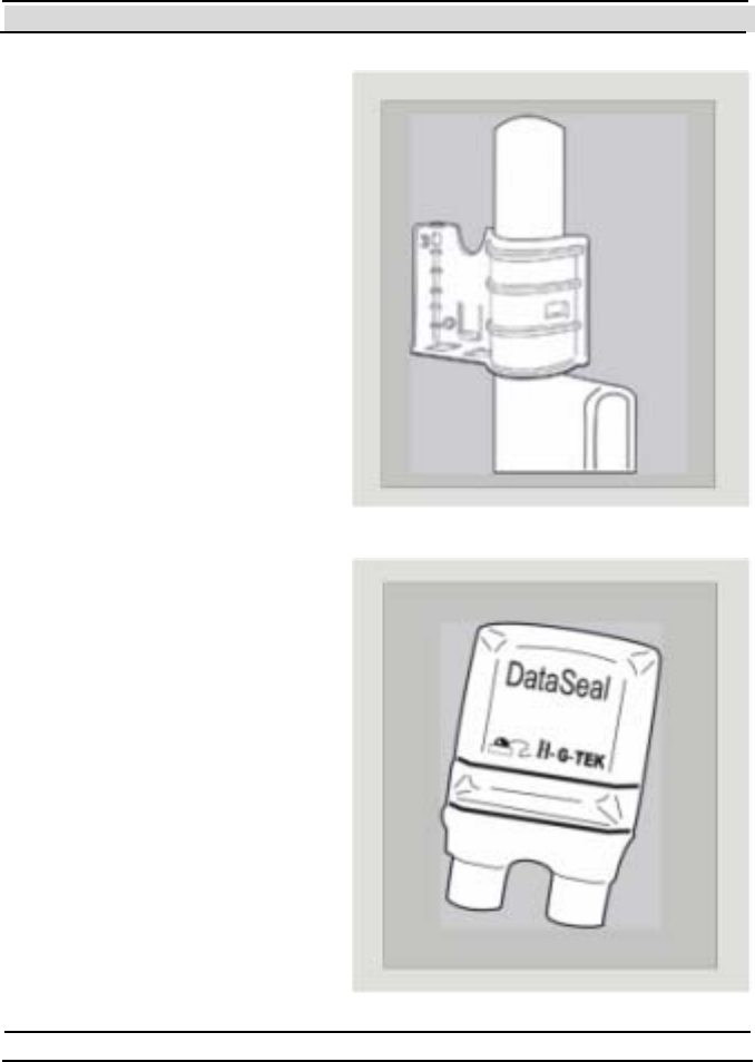
1.3.1 The Mounting
Fixtur e
The DataSeal Mount ing Fixt ure
is used to mount the DataSeal on
the container’s keeper bar or
other surface.
1.3.2 The DataSeal
The DataSeal unit contains the
DataSeal electronics, a battery, a
transceiver, a processor and
m emory t o reco rd and sto re t h e
events and the relevant
information about the cargo.
Chapter 1 Introduction
Hi-G-Tek Ltd. Micro electro nics & Asset Tracking Technology - 15 -
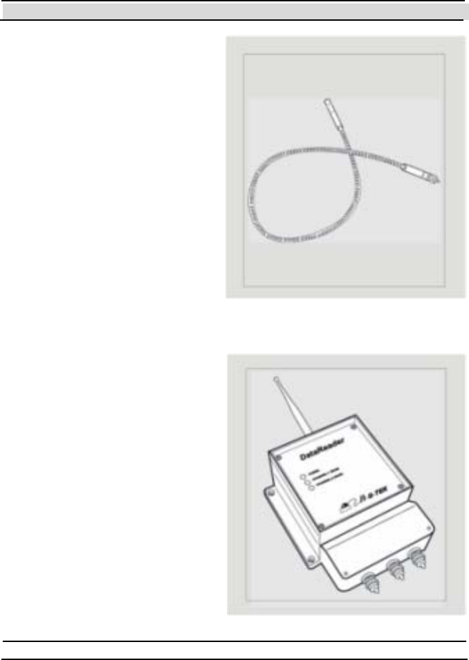
1.3.3 Sealing Wire
The Sealing Wire serves to seal
the cargo. Any tampering with the
Sealing Wire at any point during
transport is recorded and can be
reported at once.
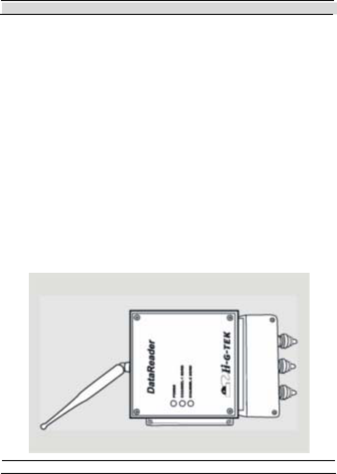
1.3.4 Outdoor DataReader
The Hi-G-Tek DataSeal System
uses st at e-of-t he-art t echnology to
secure and monitor secured
cargoes in storage and during
transport.
The DataReader is comprised of
two compartments. The upper
compartment is the heart of the
unit and cont ains the
DataReader’s electronics section.
The lower compartment contains
the terminal glands which connect
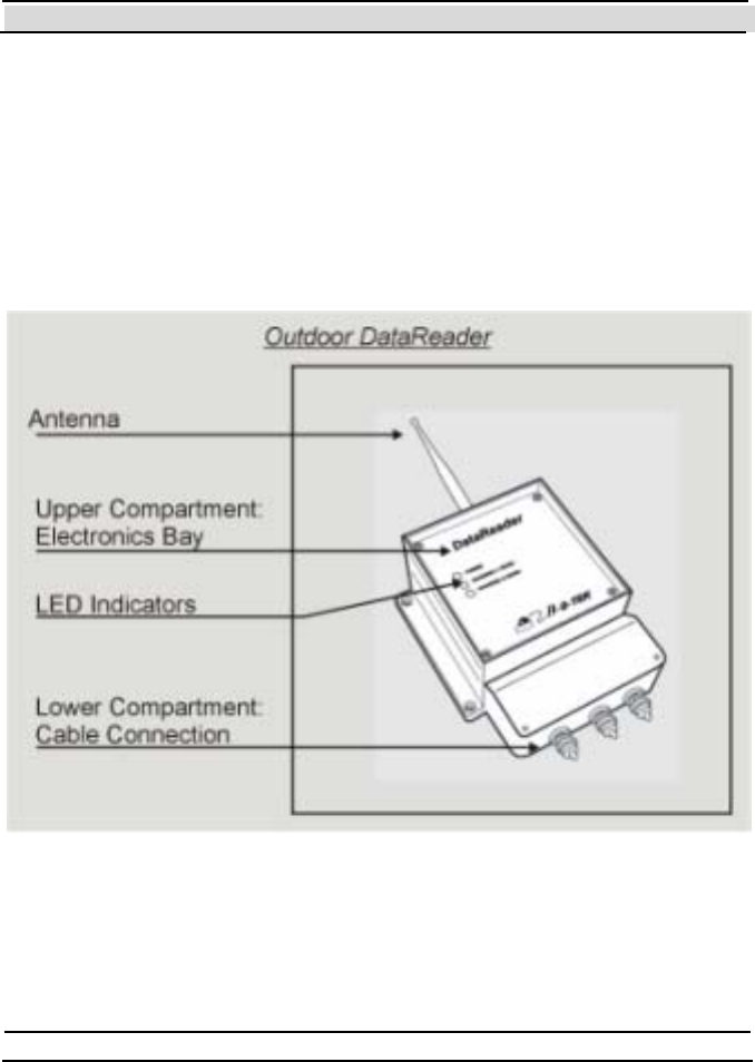
Chapter 1 Introduction
- 16 - Hi-G-Tek Ltd. Micro elec tro nics & A sset Tra cking Techno logy
the unit to the RS-232/485 networking cable.
The DataReader may be used in both st at ionary and mobile configurat ions.
In the stationary configuration, the unit is mounted on a flat surface such as
a wall or pole. A typical installation of this configuration is at the point of
exit from ports, customs terminals, warehouses, etc. This operation mode
allows monitoring of the DataSeal at predetermined sites and checkpoints.
In the mobile configurat ion, t he unit is mount ed in t he t ruck cabin. T he
DataReader monitors the seal during the entire journey, and reports its
status via the vehicle’s communication system to the control center in real-
time. T his configuration requires an additional 3rd party controlling device
to control the DataReader, or to use the TrackingDataReader which is not
covered by this manual.
Chapter 1 Introduction
Hi-G-Tek Ltd. Micro electro nics & Asset Tracking Technology - 17 -
The DataReader is mastered by a controlling computer. Once installed, the
unit waits for commands coming from the controlling computer.
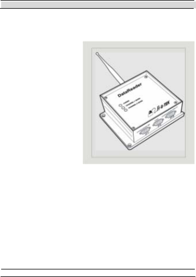
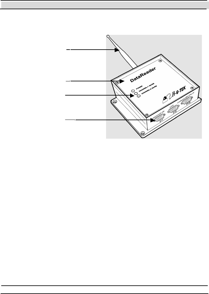
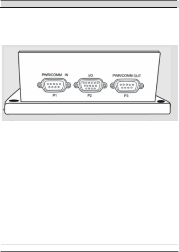
1.3.5 Indoor
Dat a Re ad er
Similar to the outdoor
version, the Indoor
DataReader uses state-of-the-
art technology to secure and
monitor secured cargoes in
an indoor environment.
The Indoor DataReader may
be use d in stat ionary
configuration only.
The unit is mounted on a flat
surface such as a wall or
pole. A typical installation of
this configuration is at the
point of closed warehouses, offices, etc.
Unlike the Outdoor DataReader, the Indoor version does not have the lower
compartment. Instead it has 3 connectors.
Chapter 1 Introduction
- 18 - Hi-G-Tek Ltd. Micro elec tro nics & A sset Tra cking Techno logy
Antenna
Electronics Bay
Led Indicat or
Cable Connection
Indoor DataReade r


Chapter 2 Quick Start
- 20 - Hi-G-Tek Ltd. Micro elec tro nics & A sset Tra cking Techno logy
2 Quick-Start
The aim of this chapter is to lead you step-by-step in the quickest way to
the stage where you can verify that the Demo System is working properly,
and that you have a simple syst em that you can play with, in order to
evaluat e the potent ial of the product s. This guide a ssumes t hat t he
parameters of the DataReader and DataSeal are the factory defaults, and it
refers only to the Demo System. For installation instructions for a
DataReader that is not a Demo System, see chapter 5.
2.1 Before you begin
Before you begin, make sure that you have the following items available:
1. The Hi-G-Tek DataReader device.
2. DataReader Antenna.
3. At least one Hi-G-T ek DataSeal device.
4. The Seal ID of the DataSeal (printed on the sticker on the bottom side
of the DataSeal).
5. Sealing Wire(s) (according to t he number of DataSeals. If you are using
DataTags you need Sensor Plate(s) instead of the Sealing Wires)
6. P C running one of the following operat ing syst ems:
• Windows 98 or above.
• Windows NT 4.0 or above.

Chapter 2 Quick Start
Hi-G-Tek Ltd. Micro electro nics & Asset Tracking Technology - 21 -
This computer must have at least one available serial communication
port, a CD-ROM drive, and at least 20MB of free hard disk space. The
computer must use an Intel PentiumTM or compatible processor.
7. CD-ROM with Evaluation Software.
2.2 Setting up the DataReaders
First, connect the antenna to the DataReader. The antenna connects to the
TNC connector at the top side of the DataReader.
Then, connect the DB9 female connector to a serial communication port in
t he PC. T ake not e of which port you are using (for example COM2). It is
good practice to connect and disconnect cables only when the computer is
off.
Plug the power chord of the DataReader into a power outlet. You should
see the POWER LED blinking red and green. After about 30 seconds it
should remain green. If it remains red, or isn't lit at all, there is a problem
with the DataReader. Refer to the chapter 0 for troubleshooting.
2.3 Installing the Evaluation Softw are
If the computer is not turned on, turn it on now, and wait until the operating
system is loaded completely.
Insert the CD-ROM labeled "Hi-G-Tek" into the CD-ROM drive.
From the Start menu, choose "Run". Assuming your CD-ROM drive is
drive E, type "E:\DataSeal Evaluation Software\Setup.EXE" in the "Run"
dialog box. If your CD-ROM drive lett er is not E, replace t he first E wit h
your CD-ROM drive letter. Click OK to start installing the DataSeal
Evaluation Software.

Chapter 2 Quick Start
- 22 - Hi-G-Tek Ltd. Micro elec tro nics & A sset Tra cking Techno logy
Follow the instructions on the screen until it says that the software is
successfully installed.
If you're using Windows 98, restart your computer (even if you're not
requested to by the installation software).
The Evaluat ion Soft ware is now inst alled. A new short cut icon "
Dat aSeal Evaluat ion" is added t o your St art ->P rograms menu.
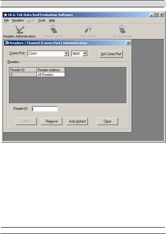
2.4 Configuring the System
Run the Evaluation Software by clicking on that icon. The Re a de r s
Administration Window shown in Figure 2-1 will be displayed.
Chapter 2 Quick Start
Hi-G-Tek Ltd. Micro electro nics & Asset Tracking Technology - 23 -
Figure 2-1 - The Readers Administration Window.
If you connected the Reader to a serial port other than COM1, choose the
appropriate COM port from the Comm Port drop down list , and t hen click
on the Se t Comm Port butt on. Click OK to close the message window that
says "Comm port was set successfully".
Click on the Au to De te ct button on the bottom of the window, to
automatically find the Reader ID of the DataReader. The message shown in
Figure 2-2 will be displayed.

Chapter 2 Quick Start
- 24 - Hi-G-Tek Ltd. Micro elec tro nics & A sset Tra cking Techno logy
Figure 2-2 - Auto Detect Warning Message.
Because you're using the Demo System that includes only one DataReader,
click Ye s .
If everything is connected appropriately, a message window will appear
saying "Reader was added successfully". Click OK to close this message.
If instead of this message, a "T imeout" message appears, check your
connections and verify that the communication port setting corresponds to
t he one you're using. Remember t o click on Set Comm Port each t ime you
change the communication port setting.
If a different message appears, refer to chapter 9 for troubleshooting.
The DataReader's ID is now added to the list with a Reader Address of 1.
Click on the Close button to close the Rea de rs Admini st rati on win do w.
2.5 Preparing the DataSeal/DataTag
DataSeals provided by Hi-G-Tek leave the factory in a special power
saving mode called "Deep Sleep Mode". Before you can communicate
normally with a DataSeal, you must send it a special command called
"Hard Wakeup" that returns the DataSeal into its normal mode of
operation. You will then have to close the Sealing Wire (as will be
Chapter 2 Quick Start
Hi-G-Tek Ltd. Micro electro nics & Asset Tracking Technology - 25 -
explained below), and send another command called "Set" that prepares the
DataSeal for normal operation.
This section describes how to prepare a single DataSeal. If you have more
than one DataSeal, repeat all the instructions in this section for each
Dat aSeal you have.
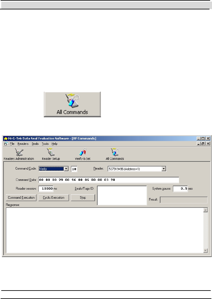
In order to send the Hard Wakeup command to the DataSeal or DataSeals
do the following:
Click on the button on the tool bar to open the
window shown in Figure 2-3.
Figure 2-3 - All Commands Window.

Chapter 2 Quick Start
- 26 - Hi-G-Tek Ltd. Micro elec tro nics & A sset Tra cking Techno logy
From the Command Code drop down list , select Hard Wakeu p.
Copy the Seal ID of the DataSeal you want to wake up into the Seals/Tags
ID t ext box. The Seal ID is print ed on t he st icker on the bottom of t he
DataSeal.
Click the Command Execution button. The mouse cursor will change to
an hourglass icon for about 11.5 seconds and then return to a normal
pointer cursor.
If the DataSeal received the message, The Re s ult box will show the
message "Command OK" in green letters. If not, verify that you typed the
Seal ID correctly in the Seals/Tags ID box, and that the DataSeal is nearby,
and try again. If you still don't get the green "Command OK" message, or
you see a different red message in the Re sul t box, refer to chapter 9 for
troubleshooting.
If you're using a Dat aSeal (as opposed t o a Dat aTag), you now have t o
close the Sealing Wire by inserting its 2 ends to the 2 sockets in the
DataSeal. Push the ends inside the sockets as far as you can. (You should
hear a 'Click' when the wire end is fully inserted). If you're using a
DataTag, you should place the Sensor Plate in its appropriate place at the
bott om of the Dat aTag.
From t he Command Code drop down list , select Set and then click the
Command Execution button. After about 4 seconds, a green "Command
OK" message should appear in the Resul t box.
Congratulations! Now your DataSeal is prepared for normal operation!

Chapter 2 Quick Start
Hi-G-Tek Ltd. Micro electro nics & Asset Tracking Technology - 27 -
2.6 Executing a Verify comm and
As a matt er of fact , if everyt hing worked fine up to this point , you can be
sure t hat your Demo System is working. Nevertheless, you probably want
to know how to perform some basic operations.
The most commonly used command is the Verify command. The main
purpose of this command is to detect which DataSeals are currently around,
and their status (opened/closed, tampered/not tampered).
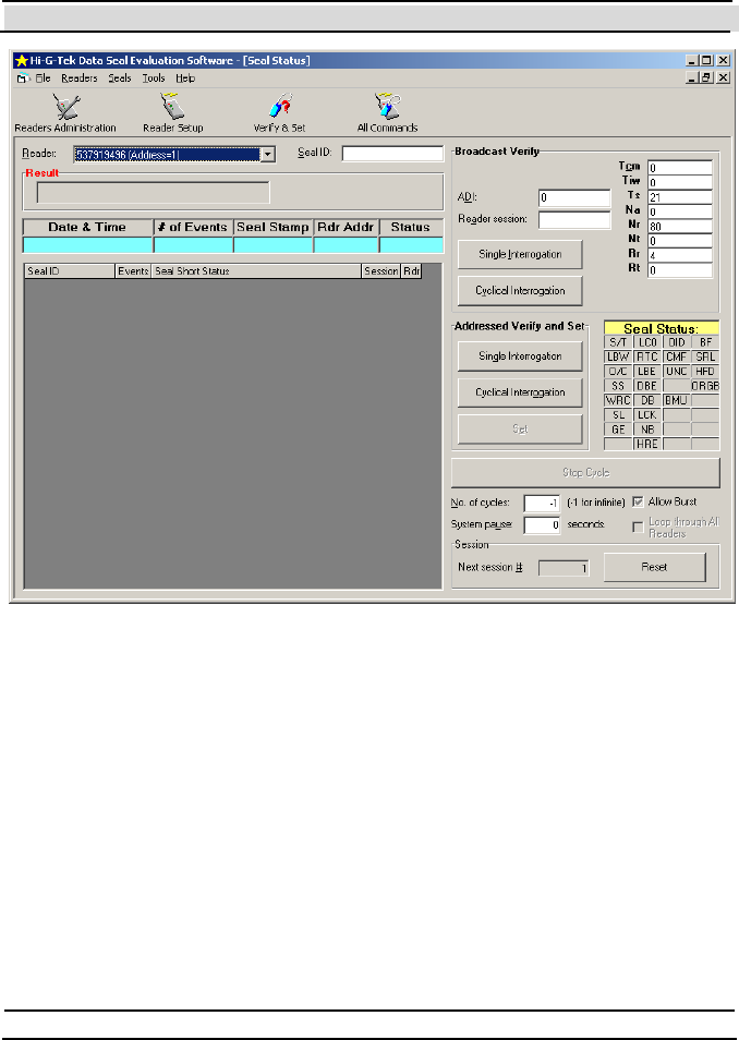
In order to execute a Verify command, open the Ve ri fy & Se t window, by
clicking on the button on the tool bar. The window shown
in Figure 2-4 will be displayed.
Chapter 2 Quick Start
- 28 - Hi-G-Tek Ltd. Micro elec tro nics & A sset Tra cking Techno logy
F igure 2-4 - The Verify & Set W indow.
Note that there are 2 buttons labeled "Single Interrogation": the upper one
resides in a rectangle labeled "Broadcast Verify", and the lower one in a
rect angle labeled "Address Verify and Set ". In t his guide, we'll only use t he
upper one (Broadcast Verify). Click this button now. After about 5 seconds,
one or more lines will be added to the list, according to the number of
DataSeals that were detected.
Figure 2-5 shows an example of a list with 5 detected DataSeals.

Chapter 2 Quick Start
Hi-G-Tek Ltd. Micro electro nics & Asset Tracking Technology - 29 -
Figure 2-5 - 5 DataSeals Detected.
Clicking the Single Interrogation button again will add another one or
more lines to the list. T o clear the list, click on the Rese t butto n at t h e
bottom of the window.
A complete explanation about the results you see is out of the scope of this
Quick-Start chapter. Nevertheless, there are 2 flags in the DataSeal's Short
Status that are worth a brief explanation here.
2.7 A Brief Tutorial Through the States of the DataSeal
The DataSeal has many flags that determine its state, as well as Parameters,
Event Records and User Data. Even though most of these features are out
of the scope of this chapter, 2 of the flags represent the most fundamental
concepts of the DataSeal. These flags are the Tampered flag (shown in
Figure 2-5 as "S/T "), and the Opened flag (shown in Figure 2-5 as "O/C").
Note that in the Evaluation Software, flags that are set appear in red, while
unset flags appear in black.
If you have followed t his guide st ep by st ep up to t his point, you should
have both flags off (black). If you cleared the list, click Single
Interrogation (the upper one) again to see the flags.

Chapter 2 Quick Start
- 30 - Hi-G-Tek Ltd. Micro elec tro nics & A sset Tra cking Techno logy
The Opened flag is set (on) whenever the Sealing Wire is open, and unset
(off) whenever it is closed. That explains why the O/C flag appears black.
Now, open the Sealing Wire by pulling one of its ends out of the socket.
Click the Single Interrogation button again to see that the O/C flag has
turned red (on).
You may have noticed that also the S/T flag has become red. This indicates
that the DataSeal was Tampered. If you now close the Sealing Wire, this
flag will remain on, even though the Opened flag will turn off again. Try it
now: close the wire, and click the Single inte rrogation once more. You
should see the O/C flag black again, but the S/T remains red.
No matter how many times you would open and close the wire now, the
Tampered flag remains set, to indicate that it was opened at least once.
You can try it if you want.
You may be wondering by now, whet her this t utorial led you to a st at e
where the DataSeal is irreversibly tampered, meaning that the DataSeal is
no longer usable! Well, you can relax because the Hi-G-Tek DataSeal is a
reusable seal, meaning that you can clear th at Tampered flag. The
Tampered flag can be cleared only when the Sealing Wire is closed, and it
is done by sending a Set command to the DataSeal. That’s right, that's the
same command you sent after the Hard Wakeup in the "Preparing the
Seal/T ag" section.
You can send this command from the Ve ri fy & Se t windows too. After
performing a Single Interrogation, click on the line in the list that shows
the Seal ID of the DataSeal you want to Set. Notice that the Seal ID now
appears in the Seal ID box at the top part of the window. You may also
type the Seal ID there manually if you prefer. Make sure that the Sealing
Wire is closed, and then click on the Set button (inside the Addresse d
Ve rify and Se t frame).

Chapter 2 Quick Start
Hi-G-Tek Ltd. Micro electro nics & Asset Tracking Technology - 31 -
After about 5 seconds, you should see a green "Set OK" message in the
Result box (in the upper left side of the window). If you see a "Set Failed"
message instead, it means that the Sealing Wire is not properly closed. If
you see a different message, refer to chapter 0 for troubleshooting.
P erform another Verify interrogation (click the Single Interrogation
button). You should see now that both the Tampered (S/T) and Opened
(O/C) flags are clear (black), just as they were in the beginning.

Chapter 3 DataSeal Installation
- 34 - Hi-G-Tek Ltd. Micro elec tro nics & A sset Tra cking Techno logy
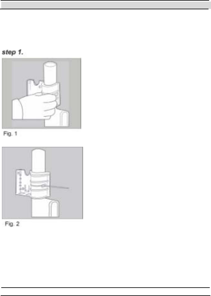
3 DataSeal Installation
To inst all t he Dat aSeal Mount ing Fixt ure,
att ach t he f ixt ur e t o t h e keep er bar at th e
back of the container (Fig.1). A click
indicates that the fixture is in place.
The two side holes may be used to secure
t he Mount ing Fixt ure t o t he container, using
a 3-5mm width by 180-250 mm length
plastic strap (Fig. 2).
Chapter 3 DataSeal Installation
Hi-G-Tek Ltd. Micro electro nics & Asset Tracking Technology - 35 -
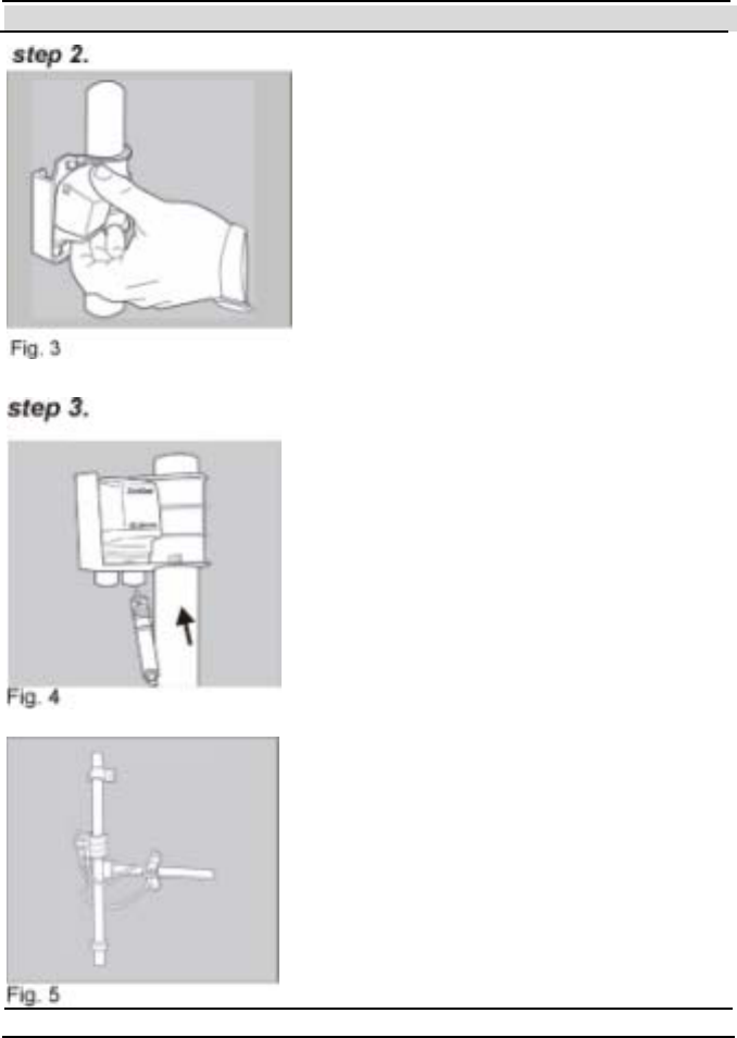
To in st all t h e Dat aSeal, ho ld t h e un it at a
45° angle as illustrated and snap it into
place in its cradle on the DataSeal
Mount ing Fixt ure. (Fig. 3)
To connect the Sealing Wire, simply attach
one end of the Sealing Wire connectors to
either of the sockets at the base of the
DataSeal (Fig. 4).
Loop t he wire t hrough t he cont ainer locking
ring and the keeper bar, then insert the end
into the other socket (Fig. 5).
Chapter 3 DataSeal Installation
- 36 - Hi-G-Tek Ltd. Micro elec tro nics & A sset Tra cking Techno logy
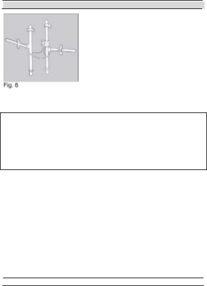
Alt ernat ively, you may loop t he wire t hrough
both keeper bars then insert the end into the
other socket (Fig. 6).
FCC ID: OB6-IGRS40916
This device complies with Part 15 of FCC rules. Operation is subject to the
following two conditions: (1) This device may not cause harmful
interference, and (2) This device must accept any interference that may
cause undesired operation.


Chapter 4 DataTag Installation
- 38 - Hi-G-Tek Ltd. Micro elec tro nics & A sset Tra cking Techno logy
4 DataTag Installation
The DataTag is delivered wit h a set of double-sided
tapes that are used for placing the DataTag on the
t agged object .
The Sensor Plate (item #1) is supplied separately
from the DataTag. To place the Sensor Plate peel
t he paper from t he double-sided t ape (it em #2) and
place the Sensor Plate in its place.
Press the Sensor Plate to the DataTag such that the
double-side d tape will hold the Sensor Plate in place.
Make sure the contacts at the bottom part of the plate are
aligned with the pins in the DataTag.
Peel the paper from the three pieces of double-sided
tape: The two larger pieces (items #3 & #4) are used for holding the
DataTag to the tagged object, while the smaller piece in the middle (item
#5) is used for pulling the Sensor Plate off
the DataTag when the DataTag is removed
from the t agged object, in order to det ect the
T am p er ev ent .
4.1 Placing the DataTag on a Vehicle
Note: The Installation instructions refer to
the case when the DataReader is installed
Vertically.
1
2
5 4
3
Chapter 4 DataTag Installation
Hi-G-Tek Ltd. Micro electro nics & Asset Tracking Technology - 39 -
There are two preferred orientations for placing the DataTag on a vehicle:
Horizontal and Vertical. These 2 options are described in the following
sections:
4.1.1 Horizontal Orientation:
Place the tag on a flat surface that is completely
horizont al and press firmly to create good cont act
between the DataT ag and the tagged object.
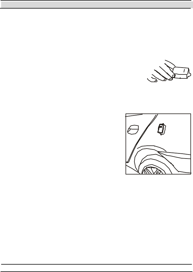
4.1.2 Vertical Orientation
Place the DataTag on a flat surface that is completely vertical, and press
firmly to create good contact between the
DataTag and the vehicle. It is recommended
t hat the height of the Dat aT ag above t he
ground will be above 3’, and the optimal
height is 5’ above ground.

Chapter 4 DataTag Installation
- 40 - Hi-G-Tek Ltd. Micro elec tro nics & A sset Tra cking Techno logy
FCC ID: OB6-IGRS40T916
This device complies with Part 15 of FCC rules. Operation is subject to the
following two conditions: (1) This device may not cause harmful
interference, and (2) This device must accept any interference that may
cause undesired operat ion.
No te: This equipment has been tested and found to comply with the limits for a
Class B digital device, pursuant to part 15 of the FCC Rules. These limits are
designed to provide reasonable prot ection against harmful interference in a
residential installation. This equipment generates, uses and can radiate radio
frequ ency en ergy and, if not installed and used in acco rdan ce with the instructions,
may cause harm ful interference to radio communications. However, there is no
guarantee that interference will not occur in a particular installation. If this
equipment does cause harm ful interference to radio o r television reception, which
can b e determined by turning the equipment o ff and on, the user is encou rag ed to
try to correct the interference by one or more of the following measures:
Reorient or relocate the receiving antenna.
Increase the separation between the equipment and receiver.
Connect the equipment into an outlet on a circuit different from that to which
the receiv er is connected.
Consult the dealer or an experien ced radio/T V technician for help.
Changes or modifications to this equipment not expressly approved by Hi-G-Tek
Ltd. could void the user’s authority to operate the equipment.

Chapter 5 DataReader Installation and Operating Instructions
- 42 - Hi-G-Tek Ltd. Micro elec tro nics & A sset Tra cking Techno logy
5 DataReader Installation
5.1 Outdoor DataReader Installation
The DataReader should be mounted on a smooth, flat surface.
To mount the unit, insert 4 screws into the holes on the unit and fix to
the surface.
A 6mm plastic anchor and 35mm pan head tapping screw is
recommended.
5.1.1 Ceiling Installation
The DataReader can be mounted on the ceiling. In such cases it is requested
to mount the antenna perpendicular to the ceiling using a 90° connector.
The figure below shows the DataReader installed on a ceiling, with the

Chapter 5 DataReader Installation and Operating Instructions
Hi-G-Tek Ltd. Micro electro nics & Asset Tracking Technology - 43 -
antenna perpendicular to the ceiling.
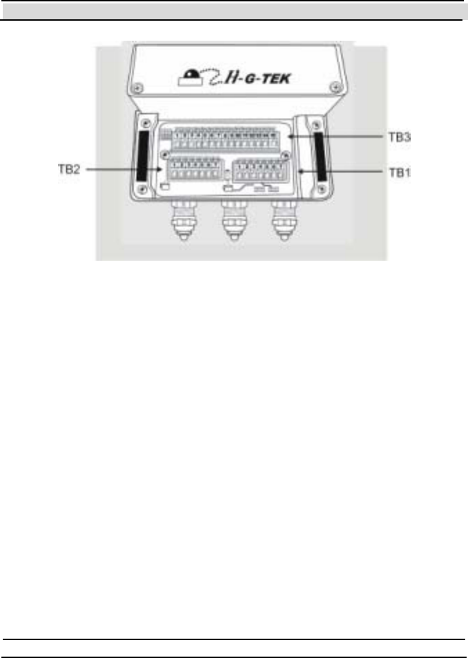
5.1.2 Connecting the Outdoor Unit
Not e : The electronics compartment panel should only be
opened by an authorized repair person. Unauthorized use may
result in loss of warranty.
Remove the cover of the bottom portion of the DataReader unit by
removing the screws holding it in place.
Remove t he covers from t he glands being used.
Expose the wires in the cable and insert them through the glands into the
terminal blocks. Use a small screwdriver to push the lever of the connector
in order to let the wires in. Ensure that the wires are inserted in the slots in
accordance with the color scheme. Wiring information for specific
configurations are given further on in the chapter.
Chapter 5 DataReader Installation and Operating Instructions
- 44 - Hi-G-Tek Ltd. Micro elec tro nics & A sset Tra cking Techno logy
5.1.3 Wiring the Outdoor DataReader
The DataReader can be communicated with via one of three types of serial
communication modes:
1. RS-485 Full Duplex
2. RS-485 Half duplex.
3. RS-232 (different model number)
According to the DataReader model in use, the serial connection can be
either RS-232 or RS-485 (see chapter 10 for technical specifications).
When the DataReader is connected using RS485, it can be set by the user to
full duplex mode or half duplex mode by alt ering a configurat ion swit ch.
For further information see sections 5.1.4 5.1.5 - 5.1.7.
Chapter 5 DataReader Installation and Operating Instructions
Hi-G-Tek Ltd. Micro electro nics & Asset Tracking Technology - 45 -
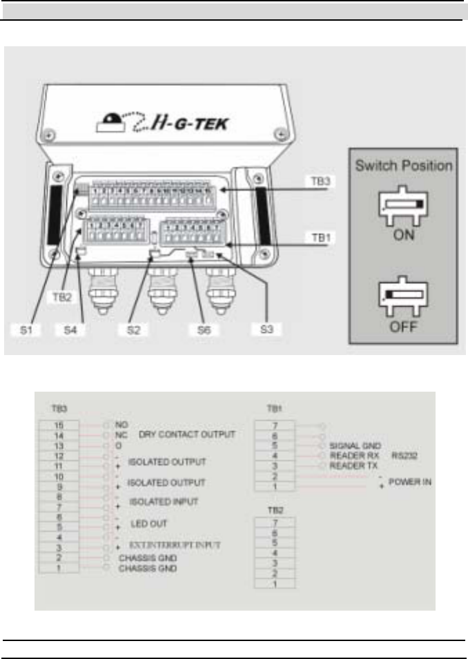
5.1.4 RS-232 Wiring Diagram
Chapter 5 DataReader Installation and Operating Instructions
- 46 - Hi-G-Tek Ltd. Micro elec tro nics & A sset Tra cking Techno logy
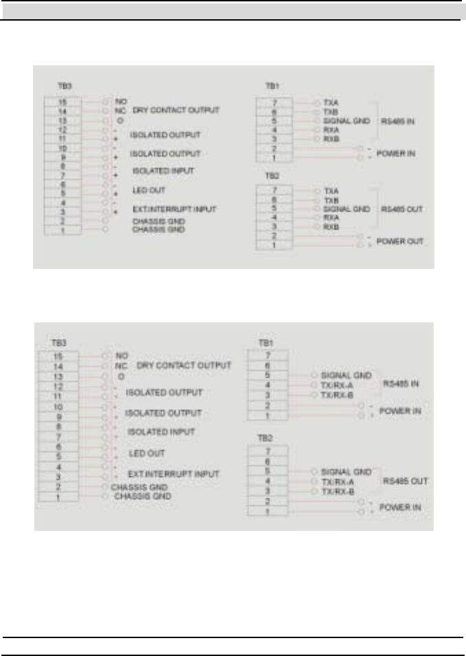
5.1.5 RS-485 Full Duplex Wiring Diagram
5.1.6 RS-485 Half Duplex Wiring Diagram
5.1.7 DataReader Configuration Sw itches
S1: Reserved for future use. Must be OFF.

Chapter 5 DataReader Installation and Operating Instructions
Hi-G-Tek Ltd. Micro electro nics & Asset Tracking Technology - 47 -
S2: Termination ON/OFF switch.
In RS-232 mode this switch does not exist. In RS-485 mode, set
this switch to ON if this is the last DataReader in the RS-485
chain. When this switch is ON, it connects an internal 120 Ohm
termination resistor to the RS485 chain.
S3, S6: Full/Half duplex switches.
In RS-232 mode this switch does not exist. In RS-485 Full
Duplex mode this switch must be ON. In RS-485 Half Duplex
mode this switch must be OFF.
S4: DataReader shut-down switch.
While OFF: DataReader is active. While ON: DataReader is not
powered. Default position: OFF
5.2 Indoor DataReader Installation
The DataReader should be mounted on a smooth, flat surface.
To mount the unit, insert 4 screws into the holes on the unit and fix to
the surface. A 6mm plastic anchor and 35mm pan head tapping screw
is recommended.
5.2.1 Connecting the Indoor Unit
Not e : The electronics compartment panel should only be
opened by an authorized repair person. Unauthorized use may
result in loss of warranty.
Chapter 5 DataReader Installation and Operating Instructions
- 48 - Hi-G-Tek Ltd. Micro elec tro nics & A sset Tra cking Techno logy
The indoor unit has three connector sockets at its base. Connector socket P1
is for incoming communications and power-in. Socket P3 is used to transfer
power and to connect the unit to the next unit in a daisy chain.
5.2.2 Wiring the Indoor DataReader
The DataReader may be connected to the network via three types of serial
communication:
1. RS-485 Full Duplex
2. RS-485 Half duplex.
3. RS-232.
Note: RS-485 and RS-232 are different models.
According to the DataReader model in use, the serial connection can be
either RS232 or RS485 (see Technical Specifications). The RS485
connector is always optically isolated.
Chapter 5 DataReader Installation and Operating Instructions
Hi-G-Tek Ltd. Micro electro nics & Asset Tracking Technology - 49 -
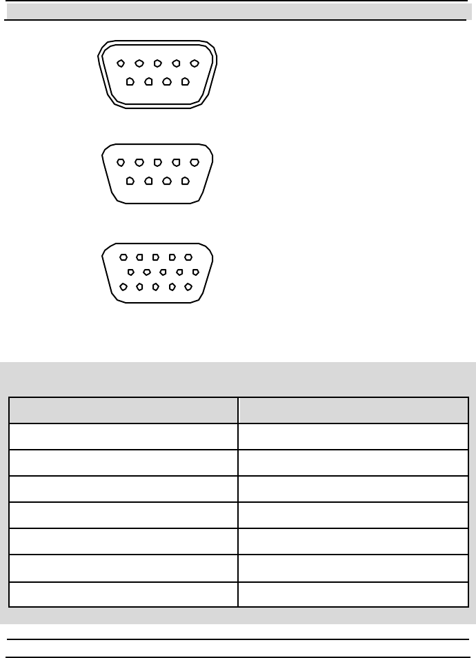
DB9 MALE
PIN ARRAGEMENT
15
69
DB9 FEMALE
PIN ARRAGEMENT
15
6
9
DB15 FEMALE
PIN ARRAGEMENT
1
56
10
1115
5.2.3 RS-232 Wiring Diagram
4. P in assignment for P WR/COM IN (P 1) & P WR/COM OUT (P 3)
Funct ion Pin Number
Positive Power 1
Positive Power 2
Signal GND 3
Negative Power 4
Negative Power 5
TX 6
RX 7
Chapter 5 DataReader Installation and Operating Instructions
- 50 - Hi-G-Tek Ltd. Micro elec tro nics & A sset Tra cking Techno logy
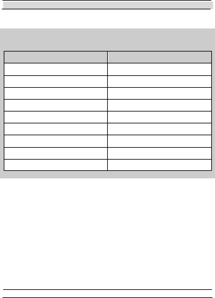
5.2.4 RS-485 Full Duplex Wiring Diagram
Pin assignment for PWR/COM IN ( P1) & PWR/COM OUT ( P3)
Funct ion Pin Number
Positive Power 1
Positive Power 2
Signal GND 3
Negative Power 4
Negative Power 5
RX-A 6
RX-B 7
TX-A 8
TX-B 9
Chapter 5 DataReader Installation and Operating Instructions
Hi-G-Tek Ltd. Micro electro nics & Asset Tracking Technology - 51 -
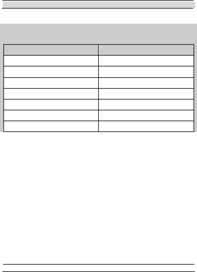
5.2.5 RS-485 Half Duplex Wiring Diagram
Pin assignment for PWR/COM IN ( P1) & PWR/COM OUT ( P3)
Funct ion Pin Number
Positive Power 1
Positive Power 2
Signal GND 3
Negative Power 4
Negative Power 5
TX/RX-A 6
TX/RX-B 7
5.3 Chaining DataReaders Together
Up to 32 DataReaders can be connected in a daisy chain using RS-485. The
last DataReader in the chain should be terminated by a 120 Ohm resistor
between the RXA and the RXB.
For the Outdoor version, the user can decide to create either an internal or
external termination switch. The internal termination switch is created by
setting to ON the termination switch (S2) of the last DataReader in the
daisy chain.
An external termination is relevant for the Indoor version only. An RS-485
to RS-232 adapter termination should be provided for the adapter receive
channel.

Chapter 5 DataReader Installation and Operating Instructions
- 52 - Hi-G-Tek Ltd. Micro elec tro nics & A sset Tra cking Techno logy
The diagram in the next page shows the connections of a system with 4
DataReaders using an RS-485 chain.
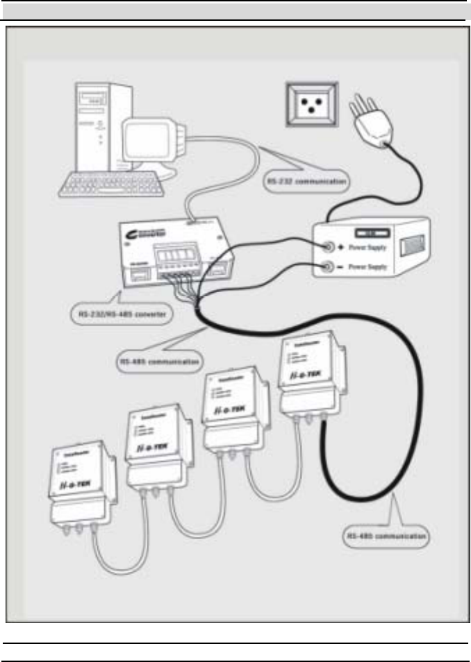
Chapter 5 DataReader Installation and Operating Instructions
Hi-G-Tek Ltd. Micro electro nics & Asset Tracking Technology - 53 -

Chapter 5 DataReader Installation and Operating Instructions
- 54 - Hi-G-Tek Ltd. Micro elec tro nics & A sset Tra cking Techno logy
5.4 RS-232/RS-485 Adapter
To connect one or more DataReaders that use RS-485 to a controlling
computer you need an RS-232 to RS-485 adapter.
Adapter’s requirements:
Full/Half duplex operation mode.
Isolated communication lines.
Recommended adapter: Moxa Technologies, model A53.
Adapter configuration: (refer to adapter’s User Manual)
1. Communication mode, either half or full duplex – according to the
DataReader configuration.
2. Txd: always enabled.
3. Rxd: always enabled.
Default configuration of the Moxa A53:
Full Duplex mode
Txd always enabled.
Rxd always enabled.
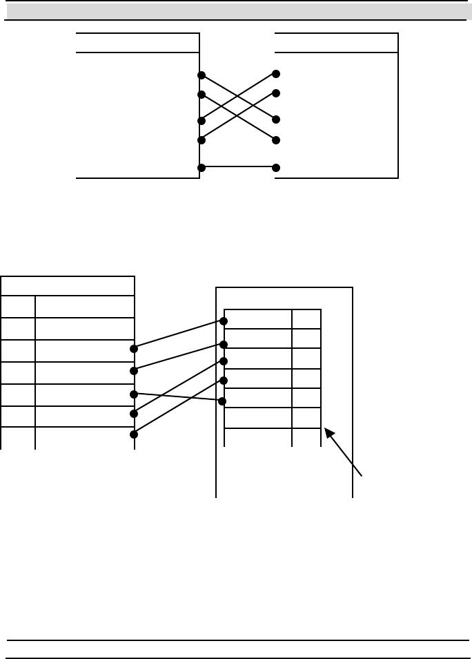
5.4.1 Connecting the RS-232/RS-485 Adapter to the First
Dat a Re ad er
The Rx and Tx lines should be crossed between the adapter and the first
DataReader as follows:
Chapter 5 DataReader Installation and Operating Instructions
Hi-G-Tek Ltd. Micro electro nics & Asset Tracking Technology - 55 -
Moxa A53 Wiring:
MOXA
TXB 1
TXA 2
RXB 3
RXA 4
GND 5
PWR- 6
PWR+ 7
Reader TB1
1 PWR+
2 PWR-
3 RXB
4 RXA
5 GND
6 TXB
7 TXA
Terminal
Block
DataReader
RXA
RXB
TXA
TXB
SIG-GND
DataReader
RXA
RXB
TXA
TXB
SIG-GND
Chapter 5 DataReader Installation and Operating Instructions
- 56 - Hi-G-Tek Ltd. Micro elec tro nics & A sset Tra cking Techno logy
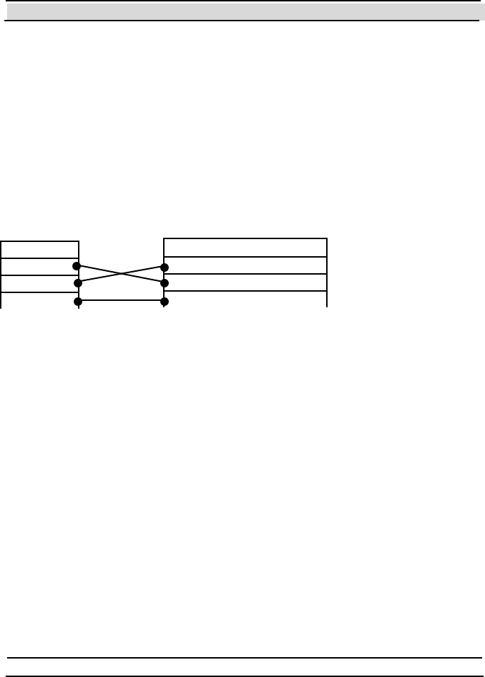
5.4.2 Connecting the RS-232/RS-485 Adapter to the
Controlling Computer
RS-232 3-wire connection should be performed between the Adapter and
the controlling computer. (Other control signals beside the Rx, Tx and
GND are not required).
Rx and Tx should be crossed as follows:
The Moxa A51 is connected to the controlling computer with RJ45/DB25
cable supplied with the adapter. If the controlling computer has a DB9
connector, a DB25/DB9 adapter should be used.
5.5 Power Supply Requirements
5.5.1 General
The DataReader supply voltage is chosen according to the model, either
12v, 24v or 48v (see the specifications of the different models in chapt er
10.
Power supply wattage: each DataReader consumes maximum 1.7W, so the
power should tolerate the number of DataReaders in the chain multiplied by
each DataReader’s power consumption.
Contr. Computer
Rx
Tx
GND
Adapter
Rx
Tx
GND

Chapter 5 DataReader Installation and Operating Instructions
Hi-G-Tek Ltd. Micro electro nics & Asset Tracking Technology - 57 -
Example: 10 DataReaders connected in a daisy chain require 10x1.7=17W
of power supply.
Note that if the power supply is installed in a high temperature area (usually
above 40° C), there is a derate in power supply wattage. (Refer to your
power supply manual).
For safety reasons, power supply current should be limited to 3A. Current
limitation should be done internally in the power supply, or externally with
a 3A fuse.
Both in t he Out door and Indoor syst ems, t he power supply should be
installed indoor.
When power supply cable ends are connected directly to system cable, a
proper isolat ion should be made. Using heat shrink t ube is recommended.
5.5.2 Indoor Installation
When the DataReader is installed indoor, the power supply used should be
UL1950 approved. A desktop style with IEC320 inlet is recommended.
5.5.3 Outdoor Installation
For safety reasons, the DataReader shall be used with the following power
supply only:
HI-G-TEK
P/N
Manufactu re r Manu factu re r
P/N
Supply
Voltage
[V]
Supply
Wattage
[W]
HGT5291A EDAC EA1050D-240 24 24

Chapter 5 DataReader Installation and Operating Instructions
- 58 - Hi-G-Tek Ltd. Micro elec tro nics & A sset Tra cking Techno logy
5.6 Cable Selection
The cable is used for power supply to DataReaders in a chain and for RS-
485 serial communication.
For most applications, 3 or 4 pairs of 24AWG shielded cable is adequate.
The serial communication requires shielded twisted pair cable, the power
supply requires low ohmic resistance of the conductors.
Cable connection:
1 pair for RXA and RXB signals.
1 pair for TXA and TXB signals.
SIGNAL GND may be connected to shield or to a pair of wires (shield
connect ion is recommended, t hough it depends on t he noise level of t he
specific environment).
For the power supply: two main issues should be considered: max current
carrying capacity and wire resistance.
Max current capacity: For 24AWG cable, the jacket is heated at 1°C at
0.1A current, max temperature is 80°C. So, this cable can carry a max of
2A at 60°C. ( (80°-60°)*0.1 ).
This calculation should be done for the application specific requirements.
Wire resistance: The voltage drop across the cable may cause insufficient
voltage to the last DataReaders in the chain. Calculation of voltage drop for
the certain setup should be done, in order to avoid this.
In most cases, the solution for such problems can be connecting a pair of
wires for the supply (2 for supply and 2 for return), using thicker cable, or

Chapter 5 DataReader Installation and Operating Instructions
Hi-G-Tek Ltd. Micro electro nics & Asset Tracking Technology - 59 -
using higher temperature rated cable. Environmental considerations: In an
outdoor installation, the cable should withstand all outdoor conditions,
including wat er proof, t emperature, ruggedness et c.
Example:
A setup of 10 DataReaders with 20 meter 24AWG cable between
DataReaders and 24v supply to the first DataReader.
The ohmic resistance between DataReaders is 3.4 Ohms (20 meter of
supply and 20 met ers of ret urn). Calculat ing the volt age drop across t he
lines gives 5v only, left to the last DataReader in the chain. T his is below
DataReader specification of DataReader minimum supply voltage. If two
conductors are used for supply and ret urn, t he ohmic resist ance would be
3.4/2=1.7 ohm. The voltage to the last DataReader in the chain would then
be 17v, well above the minimum voltage required.
If you experience difficulty calculating the voltage drop across the supply
line, cont act your dist ribut or for assist ance.
5.7 Installation Notes
The DataReader is distributed to a commercial/industrial use only, and
should only be sold to the professional customers.
When installed outdoors, the unit shall be installed in accordance with the
NEC or CEC.
Installation must be performed according to this user manual, and by a
professional personnel only.
It is the responsibility of the installer to ensure that when using the outdoor
antenna kits in the United States (or where FCC rules apply), only those
antennas certified with the product are used. The use of any antenna other
Chapter 5 DataReader Installation and Operating Instructions
- 60 - Hi-G-Tek Ltd. Micro elec tro nics & A sset Tra cking Techno logy
than those certified with the product is expressly forbidden in accordance
with FCC rules CFR47 part 15.204.
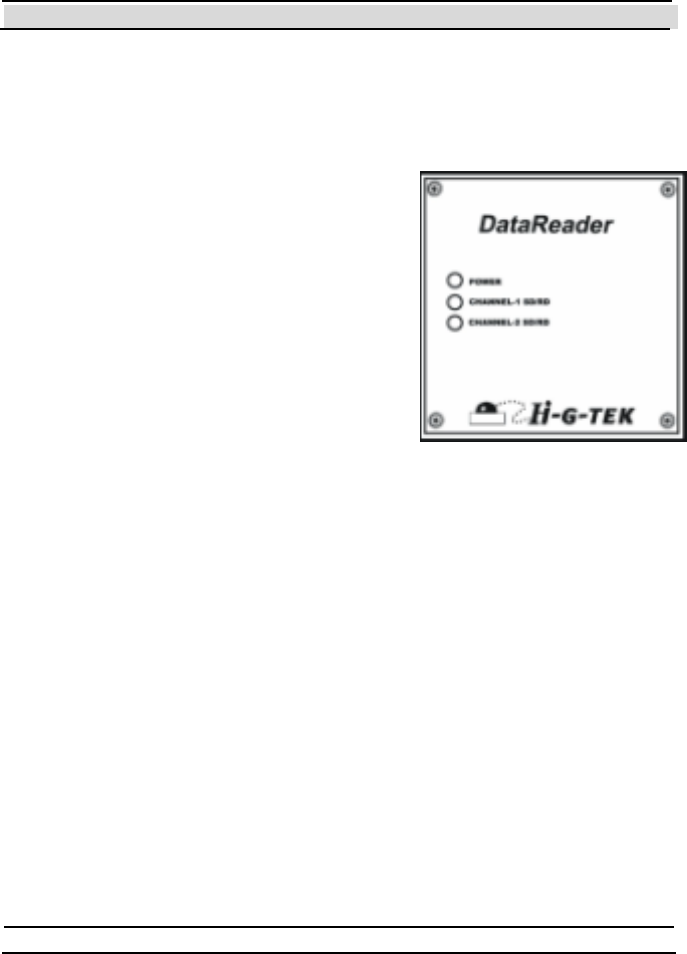
5.8 DataReader Operation Instructions
Three LED indicators are located on the left-
hand side of the electronics compartment.
5.8.1 Power Indicators:
The DataReader is activated by connecting it
t o a power supply. At power ON and self-
test the power indicator's color alternates
between green and red for several seconds.
If the check result is OK, the indicator
remains green. If a problem was det ect ed, the indicator remains red.
This LED also has a special meaning when performing firmware download:
On MCU firmware download, the indicator alternates between green
and red.
On RF Modem firmware download - the indicator remains off.
5.8.2 Channel 1 SD/RD Indicator:
When t his indicator is red, t he unit is in SD (sending RF dat a) mode.
When the indicator is green, the unit is in RD (receiving RF data)
mode.
When the indicator is off, it is in stand-by mode.

Chapter 5 DataReader Installation and Operating Instructions
Hi-G-Tek Ltd. Micro electro nics & Asset Tracking Technology - 61 -
5.8.3 Channel 2 SD/RD Indicator:
This indicator is not in use.


Chapter 6 System Overview
- 64 - Hi-G-Tek Ltd. Micro elec tro nics & A sset Tra cking Techno logy
6 System Overview
6.1 System description
The Hi-G-Tek system consists of the following components:
1. DataSeal
The DataSeal is a sophisticated device, which includes 2
transmitter/receiver units (one for high frequency/long range and another
one for low frequency/short range communications), real-time clock,
processor, memory and sensing circuitry for sealing verification. The
Sealing Wire prevents any attempt of opening, bypassing, or tampering
with the DataSeal without alerting the system and recording the event.
Data may also be written into and read from the DataSeal to store and
retrieve general information. The DataSeal can communicate both in low
frequency with short range devices, such as the DataTerminal and
MicroDataReader, and in high frequency for long ranges with the
DataReader, together allowing a broad range of applications.
2. DataTag
The DataTag is a variant of the DataSeal device. Instead of the Sealing
Wire it has a removal sensing mechanism. T his makes it more suitable for
cases where you want to tag goods, but you don't have to seal them. Other
than that, it is identical to the DataSeal device.
3. MagneticDataSeal
The MagneticDataSeal is a variant of the DataSeal device. Instead of the
Sealing Wire it has a Magnet element. This makes it more suitable for cases

Chapter 6 System Overview
Hi-G-Tek Ltd. Micro electro nics & Asset Tracking Technology - 65 -
where you want to sense if the door is open but you can’t seal it. Other than
that, it is identical to the DataSeal device.
4. DataReader
The DataReader uses in high frequency (long range) RF communication to
communicate with the DataSeals mainly for reading their IDs and their
Statuses. The DataReader can also be used for reading and writing
information to and from the DataSeal and retrieving logged events from the
DataSeal. Each DataReader can communicate with numerous DataSeals
simultaneously and verify their presence and status. The DataReaders can
also be chained together to allow a longer and wider range of coverage.
DataReaders must be connected to a controlling computer that control
them.
5. DataTe rminal (previously known as Hand Held Terminal or HHT)
This is a mobile handheld device which includes a keypad, a small LCD
screen, a low frequency receiver/transmitter, and an RS-232 interface.
The main things that you can do with the DataTerminal are: Reading a
DataSeal's ID and Status; Reset the DataSeal for a new use ("Set"
command); reading and writing data to and from the DataSeal – for
example: manifest number, truck number, driver name etc.; reading the
events that were logged in the DataSeal; T ransferring this information to
and from a PC.
6. DataPort (Previously known as Low Frequency Terminal, or LFT)
The DataPort is a simple low frequency modem. It includes a low
frequency transmitter/receiver and an RS-232 interface that connects to a
PC. In other words, it enables a PC to communicate almost directly with a
DataSeal. In general, the DataPort enables the PC to perform the same

Chapter 6 System Overview
- 66 - Hi-G-Tek Ltd. Micro elec tro nics & A sset Tra cking Techno logy
operations as the DataTerminal, given that an appropriate software exists in
the PC.
7. Mi cro Da ta Re a de r
The MicroDataReader is a key ring size mobile device that includes a lo w
frequency transmitter/receiver, 1 or 2 buttons and a LED indicator. Using
the MicroDataReader you can perform the following functions:
1. Verify – The LED will turn green if the DataSeal's Status is OK, or
to red if it's Tampered.
2. Set (Optional) – prepares the DataSeal for a new use. The type of
t he Se t c om m an d ( no rm al, So ft Set o r Susp e n de d Set ) is m o de l
specific. Hi-G-Tek can provide MicroDataReaders with different
commands if required.
6.2 DataSeal and DataReader Modes of Operation
6.2.1 DataSeal Modes of Operation
Generally speaking, a DataSeal can be used in any of the following ways:
1. O peration Mode (Normal Mode )
This is t he normal and most basic mode of operat ion. In this mode, t he
DataSeal is on standby most of the time. Once every predetermined period,
called Tw , the DataSeal samples the HF (high frequency) channel
searching for a transmission from a DataReader. If it detects such
transmission, it listens and answers as needed. The default value of T w is 3
seconds, which is the most appropriate for most applications. In the
Operation Mode, the DataSeal also listens constantly to the low frequency
channel and responds as needed. During the Operation Mode the DataSeal

Chapter 6 System Overview
Hi-G-Tek Ltd. Micro electro nics & Asset Tracking Technology - 67 -
logs events (like opened, closed, tampered, etc.) and stores them internally
in t h e E v ent s Mem o ry .
2. Dee p Sle e p Mo de
This mode should be used when the DataSeal is not in use in order to
conserve energy. DataSeals always leave the factory in this mode. It is
possible to ent er a Dat aSeal t o t his mode also by using high frequency or
low frequency command. To exit this mode, interrogate the DataSeal using
low frequency (for example, using a DataTerminal), or send a Hard
Wakeup command in high frequency using a DataReader.
Note: While in Deep Sleep mode, no Events are recorded. Events aren't
recorded also after waking up the DataSeal, until a Set command is
performed. In other words, after waking up a DataSeal, you must also
perform a Set command in order for the DataSeal to start record events.
3. Alert Burst Mode
This mode is similar to the Operation Mode. In addition, whenever the
DataSeal is opened, it transmits an Alert Burst message in the high
frequency channel. The DataReader and the application should both be
configured to receive and handle the alert message. A DataSeal can be
configured also to t ransmit Burst messages on other events.
4. Footprint Events Mode
This mode is a way of using the DataSeal, rather than a configuration of the
DataSeal. When the DataSeal receives a special variant of the Ve ri f y
command in low frequency or in high frequency, it records a certain Event
called "Read", that includes the DataReader's ID or the low frequency
device's ID. To use this special command in the DataReader, the
DataReader has to be configured accordingly. This mode is useful to
determine the DataSeal's track if there are several DataReaders, or check

Chapter 6 System Overview
- 68 - Hi-G-Tek Ltd. Micro elec tro nics & A sset Tra cking Techno logy
points with DataTerminals along the way. In this scenario, you can know
the DataSeal's track by reading its Events, without having to have these
DataReaders connected to any central system.
6.2.2 DataReader Modes of Operation
There are several aspects that determine the DataReader's mode of
operation. T hese aspects are determined by the Mode parameter, which is a
bit orient ed parameter.
5. Carrier Sense Collision Prevention
Just like you can't understand what two people are saying when the speak
simultaneously, that way a DataSeal can't understand two DataReaders that
transmit simultaneously. When two (or more) close DataReaders aren't
controlled by the same controlling computer (or by controlling computers
that are synchronized among them), there's a chance that they will try to
transmit simultaneously. In order to prevent that, the DataReaders can be
configured to sense for a carrier (transmission of another DataReader or
DataSeal) before they start transmitting. When a DataReader is configured
for Carrier Sense, each time before it transmits something it listens to the
frequency, and only if it's clear (no one else is transmitting), it start
transmitting it s own message.
6. Burst Re cei vin g Mode
When DataSeals are operating in Alert Burst mode, the DataReader’s
receiver must be ON at all times in order to receive the Burst messages.
The controlling computer has to query the DataReader periodically to
receive the Burst messages that the DataReader received.

Chapter 6 System Overview
Hi-G-Tek Ltd. Micro electro nics & Asset Tracking Technology - 69 -
6.3 Most Common Commands and Seal Status
6.3.1 Most Commonly Used Comm ands
There are a number of key commands that are used in most applications, as
they enable the basic operation of the system. These commands are:
7. Verify
The Ve ri fy command is used to detect DataSeals which are located within
the DataReaders Receiving Zone and also verify their state. The DataSeals
which respond may be in one of two states. The DataSeals may be in either
the normal state, meaning the have not been tampered with, or in the
tampered state, meaning they have been tampered with. Additional
information can also be queried from the DataSeal. This is the most useful
and commonly used command in the system.
8. Tampered
The Tampered command is used to communicate with tampered
DataSeals. The command operates the same as the Ve ri fy command only
DataSeals which are in the Tampered state respond. T he aim of the
command is to provide high priority to tampered DataSeals in a crowded
DataSeals environment.
9. Set
The Set command is used to set a DataSeal for a new use. The Sealing
Wire must be connected and closed in order for a DataSeal to be set. The
Se t command deletes all Events stored in the Events Memory and is the
first new Event recorded in the DataSeal. The DataReader can send the Se t
command to up to 8 DataSeals simultaneously.
10. Suspended Set

Chapter 6 System Overview
- 70 - Hi-G-Tek Ltd. Micro elec tro nics & A sset Tra cking Techno logy
Similar to the Set comman d, Suspended Set is used to set a DataSeal for
new use. Unlike the Set command, when performing a Suspended Set
command, the Sealing Wire Must be opened (or completely disconnected
from the DataSeal). T he DataSeal will become armed (Set) once the
Sealing Wire has been connected to the DataSeal and closed.
11. Approve Open
The Approve Open command allows a Sealing Wire to be opened after the
DataSeal has been set in a way that the application can determine that the
DataSeal was opened with an approval. When the Sealing Wire will be
opened after receiving this command, the application will be a ble to
det ermine that t he opening is approved by examining the Approved Open
flag in the DataSeal's Status.
6.3.2 DataSeal's Status
The DataSeal's Status consists of 4 bytes. A DataReader may be used to
request the DataSeal's Status. The DataSeal's Status is used to indicate the
DataSeal's current state and is a bitwise value. Each bit in the Status
represents a specific status flag. The DataSeal's Status is divided into the
Short Status and Long S tatus parameters as explained below:
The DataSeal's Short Status parameter consists of 1 byte (8 bits) which is
a subset of the Long Status parameter. The Short Status contains the most
important flags. These flags are:
1. Tampered – The Tampered flag gets set if the Sealing Wire was
opened or tampered with. It remains set even if the Sealing Wire is
closed again. It can only be unset by performing on of the Se t
commands.
2. Low Battery Warning – Battery is low, replace the DataSeal.
3. Opened – Indicates that the Sealing Wire is open.

Chapter 6 System Overview
Hi-G-Tek Ltd. Micro electro nics & Asset Tracking Technology - 71 -
4. Suspende d Se t – A Suspende d Set command was performed, and the
Sealing Wire wasn't closed yet.
5. Se aling Wi re Ch ange d – Indicates that the Sealing Wire's electronic
characteristics have changed since the DataSeal was Set.
6. Deep Sleep – Indicates that the DataSeal is in Deep Sleep mode.
7. General Error – Indicates an error with the DataSeal that is not
represented in the DataSeal's Short Status.
8. Approve d O pen – If the DataSeal Opened flag is on, the Approved
Open flag means that the opening is approved. If the DataSeal's
Opened flag is off, it means that the next open will be approved, if
performed during a certain period.
The DataSeal's Long Status contains the Short Status flags as well as 3
additional bytes that together represents the complete DataSeal's status. For
a det ailed descript ion of the Long Status, see chapter 8.
6.4 System Planning
When planning an application, attention should be paid to both system
operat ion and topology. Applicat ion requirement s and elect romagnet ic
environment characteristics should also be taken into account.
2 basic types of applications are possible: Fixed DataReader applications
and Mobile DataReader applications. A complex application that combines
DataReaders in both configurations is also possible.
The Fixed DataReader applications are applications where the DataReaders
are mounted at a fixed site. The Mobile applications are situations where
the DataReaders are mounted on vehicles for monitoring DataSeals in
transit. Mobile applications are normally implemented using the
TrackingDataReader, but may also be implemented using a DataReader

Chapter 6 System Overview
- 72 - Hi-G-Tek Ltd. Micro elec tro nics & A sset Tra cking Techno logy
connected to any mobile controller (E.g. laptop, palmtop, etc), that has a
serial communications port.
6.4.1 Electrom agnetic Environment
Radio Frequency Communicat ion is t he basic t echnology used by t he
system. While this is a very robust method for communicating with remote
devices, several issues should be considered when planning a site.
Metal walls should not be used to shield the remote devices.
Communication distance between remote devices may vary due to
atmospheric conditions and other electromagnetic interferences.
Communication distance may also vary according to one or more of the
following:
• Line of sight between devices – existence and clearance.
• Proximity to metal objects.
• Indoor or Outdoor environment.
• Antenna orient at ion bet ween the devices.
It is recommended to map the site with actual devices for proper coverage.
When planning the site layout, safe margins should be taken into account to
ensure proper operation at all times. Possible environmental changes
should also be considered.
6.4.2 System Layout
Two aspects should be considered when dealing with system layout:
1. Radio Frequency Communicat ion Layout .
2. Line Communication RS-485 or RS-232 Layout.

Chapter 6 System Overview
Hi-G-Tek Ltd. Micro electro nics & Asset Tracking Technology - 73 -
6.4.2.1 Radio Frequency Communication Layout.
When only one DataReader is in use, the previously mentioned
environmental considerations are all that need be taken into account.
When more than one DataReader is in use, it should be understood that in
the same area only one DataReader can communicate with the DataSeals at
the same time. Interference will be caused by more than one DataReader
Trying to communicate with the DataSeals in the same period of time. Th e
DataReaders should be synchronized using the application software or
using the Carrie r Sense mode. Several DataReaders may operate
simult aneously provided t hat it has previously been confirmed t hat they
will not interfere with each other.
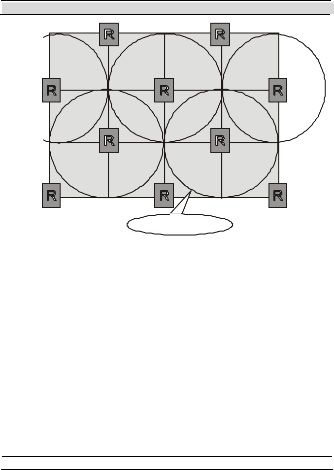
6.4.2.1.1 Cellular Layout
Cellular topology should be used to ensure efficient coverage of a large
area. The following diagram illustrates the concept:
Chapter 6 System Overview
- 74 - Hi-G-Tek Ltd. Micro elec tro nics & A sset Tra cking Techno logy
DataReaders must be properly placed to ensure there are no dead zones
within the defined area. Overlaps should be as shown in the above drawing.
DataReader's Receiving Zone is the term used to describe the area of
reliable communication covered by a DataReader. The DataReader's
Receiving Zone is also called a Cell. As the drawing illustrates, it is
extremely important that the application software controls and synchronizes
the DataReader’s operation in order to avoid RF collisions. In other words,
the application software has to make sure that no two DataReaders with
overlapping Receiving Zones transmit at the same time.
6.4.2.2 Line Communication RS-485 Layout
The connection of many DataReaders to a controlling computer is done via
the RS-485 protocol. Up to 32 DataReaders may be connected to one serial
Reader Zo ne

Chapter 6 System Overview
Hi-G-Tek Ltd. Micro electro nics & Asset Tracking Technology - 75 -
communications port, depending on the type of RS-485 to RS-232
converter used.
T wo topologies can be used:
A long daisy chain connection, where all the DataReaders are
connected in one long line.
A star-type connection, where the DataReaders are split into groups
and each group is connected directly to the converter.
It is recommended that the second alternative be used wherever possible. A
star-type connection provides better tolerance to connection failures. This
alternative is also preferable from the power supply point of view, as only
one power supply for the DataReaders is necessary. The power supply
should be located near the converter. When the line is divided into
segments, the voltage drop along the segments is smaller.
6.5 Systems Segregation
When Hi-G-T ek has designed the system, several security and operational
considerations have been taken into account:
Similar equipment belonging to one company should not be able to
mess with another company's system either intentionally or
unintentionally.
Limit unauthorized access between different departments of the same
company. Equipment belonging t o one depart ment of a company
should not be able to interfere with equipment of another department,
either intentionally or unintentionally.
Service Providers should be able to communicate with their customer's
equipment in order to supply common services to several companies.
This should be done in an authorized an limited manner.

Chapter 6 System Overview
- 76 - Hi-G-Tek Ltd. Micro elec tro nics & A sset Tra cking Techno logy
Dat aSeals may have to be divided int o groups that are not related t o
companies or depart ment s.
6.5.1 Com panies Segregation by OrgID
OrgID is a unique value assigned to each company by Hi-G-Tek or by one
of its authorized dealers. Every device supplied to that company is pre-
programmed with the same OrgID at product ion, and t he cust omer can't
change it ever again. In every communication between two devices, the
caller (e.g. DataReader) sends its own OrgID value. When the consignee
(e.g. DataSeal) receives the message, it first compares the OrgID it received
with its own OrgID, and only if they match the consignee performs the
command and sends its response. If a DataSeal receives a message a
different OrgID than its own, it turns on the Ille gal O rgID flag in the Lon g
Status, and ignores the message.
There's one exception in which a DataSeal can respond to a message with a
different OrgID in order to allow collaborat ion with service providers. This
is described in more det ails in sect ion 6.5.3.
6.5.2 Department Isolation
Department is a unique value assigned by a company to a group of devices
belonging t o the same depart ment . It is possible to isolat e equipment
bet ween depart ment s by using t he Department parameter in the various
devices.
The default value of Department is zero in all devices. When set to that
default sett ing, all t he devices can communicat e wit h one anot her without
any limitations.
If a DataReader's Department value is not zero, it can communicate only
with DataSeals that has the same Department value.

Chapter 6 System Overview
Hi-G-Tek Ltd. Micro electro nics & Asset Tracking Technology - 77 -
If a DataReader's Department value is not zero, it can communicate with all
of the DataSeals in the same organization, even if their Department value is
non-zero. Such a DataReader is considered "Supervisor". The Department
parameter both in DataReaders and in DataSeals can be changed by the
user at any time.
6.5.3 Services to Several Companies by a Service Provider
The DataSeal has a boolean parameter named Gl obal, which is designed to
allow a Service Provider to service several customers. If a DataSeal’s
Global parameter is on, then that DataSeal will respond to any Ve ri f y
command from any DataReader, regardless of OrgID. T he Ve rif y response
will be a limited one, containing only a certain few of the DataSeal
parameters. See the description of the Global paramet er in chapt er 8 for a
list of the parameters that can be included in the Ve rify response in this
case.
Note: The Global paramet er is programmed during product ion, and it
mu st be de fi ne d an d re ques te d i n a dvan ce .
6.5.4 Subgroups of DataSeals
When a DataReader sends a Verify command In order to detect the
DataSeals in its area, it can receive only a limited number of responses at a
time. If there are many DataSeals in the DataReader's Receiving Zone there
could be too many DataSeals trying to respond at the same time, and that
would cause that none of them will be properly received by the
DataReaders. In order to avoid that, the DataSeals can be divided into small
groups and each group be assigned a unique value called ADI. When the
DataReader will execute a Ve rif y command, it would be able to specify a
specific group, and only DataSeals that belong to that group will respond. If
the DataReader would iterate through the groups, it can receive all the
DataSeal in a relatively short time.

Chapter 6 System Overview
- 78 - Hi-G-Tek Ltd. Micro elec tro nics & A sset Tra cking Techno logy
For that purpose, the DataSeal and DataReader devices have an ADI
parameter. The ADI parameter works very similar to the De pa rtmen t
parameter, with 2 differences: ADI is 4 bytes while Department is 1 only
byte, and the controlling computer can explicitly specify a different ADI
for each RF command it requests the DataReader to transmit.
The ADI parameter can be used also to create groups by usage in other
scenarios.
6.5.5 OrgID, Department, Global and ADI Impact on DataSeal’s
Response
The following statements summarizes when and what a DataSeal responds:
1. If the DataReader's Department parameter is zero, the De pa r tme n t is
always considered to match.
2. If the DataReader sends a zero ADI, the ADI is always considered to
match.
3. OrgID doesn't match and Gl obal is on: DataSeal will respond with
limited Ve rif y command only.
4. OrgID doesn't match and Gl obal is off: DataSeal will not respond.
Table 6-1 : OrgID and Global
OrgID Global Effect:
Unmatched ON DataSeal will respond with
limited Verify command
only
Unmatched OFF DataSeal will not respond

Chapter 6 System Overview
Hi-G-Tek Ltd. Micro electro nics & Asset Tracking Technology - 79 -
5. OrgID matches, De pa rtme n t matches, and ADI matches: DataSeal
will respond without limitations.
6. OrgID matches, and ADI doesn't match: DataSeal will not respond.
Table 6-2 : OrgID, Department, and ADI
OrgID Department ADI Effe ct:
Match Match Match DataSeal will Respond
without any limitations.
Match Match/
Unmatched
Unmatched DataSeal will not
respond
Match Unmatched Matched/
Unmatched
DataSeal will not
respond
Unmatched Match/
Unmatched
Match/
Unmatched
DataSeal will not
respond
6.6 DataSeal's Memory
The DataSeal's Memory is divided int o 2 sect ions: Event s Memory and
User Data.
6.6.1 Events Mem ory
This memory stores the Events detected by the DataSeal during normal
operation. This memory can contain up to 55 Event records.
The memory has a FIFO type structure with 2 segments: The first segment
can store 45 Events and is a simple FIFO buffer. The second segment can
store 10 Events and is a cyclic buffer with the last Events detected.

Chapter 6 System Overview
- 80 - Hi-G-Tek Ltd. Micro elec tro nics & A sset Tra cking Techno logy
When this cyclic buffer is overrun, the Scroll flag in the Long Status is set.
The Se t Event is always the first Event record in the Events Memory.
Se t Event
First
segment :
45 Events
Second
segment : 10
Events
Some Events are caused by an external intervention (like Opened and
Closed), while others are caused by internal procedures.
The most common Events are the Se t, Tampered, Opened an d Close d
Events. See chapter 8 for a complete list and descriptions of each Event
type.
6.6.2 User Data
User Data is the memory segment where free data can be written and read.
For example, the electronic manifest can be stored in this memory.
The User Data can be read and written using the Rea d Da ta and Write
Data RF commands accordingly. The User Data can also be read by the
Verify an d t h e Read Multi Access Data RF commands. The size of the
User Data memory segment is 2KB.

Chapter 6 System Overview
Hi-G-Tek Ltd. Micro electro nics & Asset Tracking Technology - 81 -
Even though all the User Data is simply a flat memory segment, the lowest
53 bytes are of special meaning for the DataTerminal. If you're using or
considering to use a DataTerminal in your system someday in the future,
you should use these 53 bytes in a way that is compatible with the
DataTerminal. The DataTerminal uses the first 53 bytes as follows:
6.6.2.1 The User Data portion used by the DataTerminal
The DataT erminal is capable of viewing and editing 48 bytes (addressed 5
– 52) of the User Data as a structure of ASCII fields. This structure has to
be defined first by t he user, using a special P C soft ware provided wit h t he
DataTerminal, and then uploaded to the DataTerminal. The structure
definition includes the labels and sizes of the fields and is assigned an
identifier (called UDT), and a version number. When the user writes User
Data using the DataTerminal, the DataTerminal always stores this identifier
and version number in address 0, and the date and time when the data was
written, in addresses 1-4.

Chapter 6 System Overview
- 82 - Hi-G-Tek Ltd. Micro elec tro nics & A sset Tra cking Techno logy
Table 6-3: Memory map of the lower po rtion of the User Data.
Address Byte Content
0 UDT Version
1
2
3
4
Time & Date
5
.
.
.
52
Data
6.7 System Comm ands
The following list describes t he commands t hat can be sent t o one or more
DataSeals by the DataReader. For more information about each command
see chapter 8 and the DataSealLib COM DLL help file.
1. Verify – Uses to detect DataSeals located inside a DataReader's
Receiving Zone.
2. Tampered – Uses to detect DataSeals located inside a DataReader's
receiving zone that are in the Tampered state.

Chapter 6 System Overview
Hi-G-Tek Ltd. Micro electro nics & Asset Tracking Technology - 83 -
3. Set – Uses to prepare DataSeals for a new use. Sealing Wire must be
attached and closed prior to the Set command. This command can be
sent up to 8 DataSeals simult aneously.
4. Suspende d Set – Similar to the Se t command except that the Sealing
Wire must be open prior to performing the command and the DataSeal
gets set once the Sealing Wire is closed. This command can be sent to
up to 8 Dat aSeals simult aneously.
5. Soft Set – Similar to the Se t command, the Soft Set command is used
to prepare DataSeals for a new use. Unlike the Se t command, the Soft
Se t command does not delete the previously recorded Events in the
Event s Memory. This command can be sent t o up t o 8 Dat aSeals
simultaneously.
6. Deep Slee p – Puts the DataSeal into Deep Sleep mode. T his command
can be sent to up to 8 DataSeals simultaneously.
7. Hard Wakeup – Brings DataSeals which are in Deep Sleep mode back
t o normal operat ing mode. This command can be sent to up to 8
DataSeals simultaneously.
8. Start Alert Burst Mode – Puts DataSeals into Alert Burst mode. This
command can be sent to up to 8 DataSeals simultaneously, or to all the
receiving DataSeals.
9. Stop Alert Burst Mode – Brings DataSeals which are in Alert Burst
mode back to normal operat ing mode. This command can be sent to up
to 8 DataSeals simultaneously, or to all the receiving DataSeals.
10. Acknowledge Alert Burst – Acknowledges the reception of Alert
Burst messages from DataSeals. T he Ackno wle dge Ale rt Bu rs t
command tells the DataSeal that its message has been received. After
receiving an Ackno wle dge Ale r t Bu rs t command, the DataSeal stops
transmitting its Burst message until a new Tampered event is detected.
This command can be sent to up to 8 DataSeals simultaneously.
11. Read Data – Retrieves data from a DataSeals’ User Data area.

Chapter 6 System Overview
- 84 - Hi-G-Tek Ltd. Micro elec tro nics & A sset Tra cking Techno logy
12. Write Data – Writes data into a DataSeal's User Data area.
13. Reset Data – Erases all the data in a DataSeals’ User Data area.
14. Se t/Reset Status – Sets or resets specific flags of the DataSeal’s Lon g
Status.
15. Write Parameters – Writes new values to one or more DataSeal
parameters.
16. Read Parameters – Reads the values of one or more DataSeal
parameters.
17. Addressed Verify – The Addresse d Verify command is the same as
the Verify command except that it is applicable to only one DataSeal.
This command is most commonly used to verify that a specific
DataSeal is located within a DataReader’s Receiving Zone.
18. Multi Addressed Verify – T he Multi Addresse d Ve rify command is
the same as the Addressed Verify command, but is applicable t o up t o
7 DataSeals simultaneously.
19. Read Eve nts – Reads part of or all Events stored in the DataSeal’s
Events Memory.
20. Approve Open – Permits to open a DataSeal after it has been Se t. If
opened, both the DataSeal's Approve d O pen and the Tampered flags
will be set. This command is intended for recognizing permitted
DataSeal openings.
21. Start Forced Burst – Forces the DataSeal to send a special Burst
message called Forced Burst. It is most useful when this command is
executed in Low Frequency, and by that causing the DataSeal to send
information to the DataReader. When used in high frequency, it may be
executed in one DataReader, while a different DataReader (in another
place for example), should receive the Fo rce d Bu rs t message.
22. Temporarily Disable HF – Disables the HF channel in a DataSeal for
a specified period. This is useful to conserve battery when the area may

Chapter 6 System Overview
Hi-G-Tek Ltd. Micro electro nics & Asset Tracking Technology - 85 -
be dense with HF communications that don't apply to that DataSeal, or
to prevent the DataSeal from responding to a Ve ri f y command for a
certain period, in order to allow other DataSeals to be received.


Chapter 7 Evaluation Softw are
- 88 - Hi-G-Tek Ltd. Micro elec tro nics & A sset Tra cking Techno logy
7 Evaluation Software
Hi-G-Tek provides the DataSeal Evaluation Software for it s customers in
order for t hem to get an impression of how t he syst em works. Using t he
Evaluation Software you can play with many of the system's features and
examine its behavior.
If you're reading this manual chapter by chapter, you should now have an
idea of how the system works but lacking the details. Before going into the
details in the next chapters, getting to know the Evaluation Software is just
the right thing to do in order to have a tool that allows you to play with the
"bit s and byt es" of t he various commands.
7.1 Softw are Installation
If you have an older version of the Evaluation Software you should first
remove it (from the "Add/Remove Programs" icon in the Control Panel)
Insert the CD-ROM labeled "Hi-G-Tek" into the CD-ROM drive.
From the Start menu, choose "Run". Assuming your CD-ROM drive is
drive E, type "E:\DataSeal Evaluation Software\Setup.EXE" in the "Run"
dialog box. If your CD-ROM drive lett er is not E, replace t he first E wit h
your CD-ROM drive letter. Click OK to start installing the DataSeal
Evaluation Software.
Follow the instructions on the screen until it says that the software is
successfully installed.
If you're using Windows 98, restart your computer (even if you're not
requested to by the installation software).
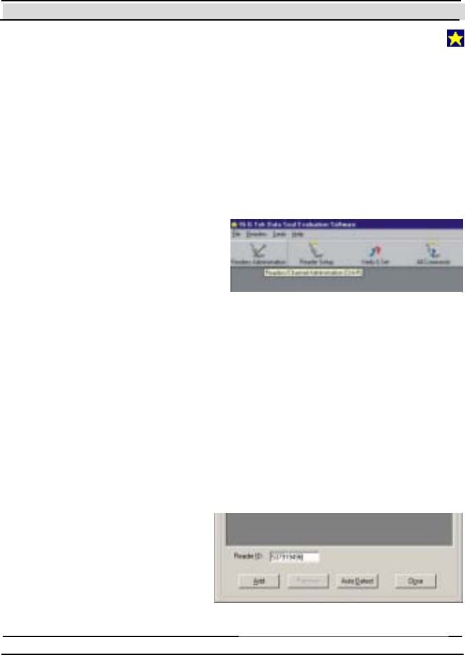
Chapter 7 Evaluation Softw are
Hi-G-Tek Ltd. Micro electro nics & Asset Tracking Technology - 89 -
The Evaluat ion Soft ware is now inst alled. A new short cut icon "
Dat aSeal Evaluat ion" is added t o your St art ->P rograms menu.
7.2 Comm unication Setup – The Readers Adm inistration
Window
The Evaluation Software must know which DataReaders are connected to
the computer as well as the serial communication port they're connected to
and the baud rate of t hat port .
The Evaluation Software supports
up to 32 DataReadres connected
using RS-485 to a single
communication port or a single
Dat aReader connect ed using RS-
232. Configuring the DataReaders,
communicat ion port and baud rat e
is done t hrough t he Readers Administration window.
The Re a de rs Admini st rati on window can be accessed by clicking on the
Reade rs menu butt on on the top of the screen, and then on Re a de r s
Administration. Alternatively, click on the Readers Administration icon
(Figure 7-0) or press Ct rl+R.
7.2.1 Defining the Connected DataReaders
To add a DataReader, insert the Reader ID in the Reader ID t ext box and
click on the Add button (Figure
7-0). The Reader ID is located
on the back of the DataReader,
in barcode and in numeric
format. To remove a
DataReader, use the mouse to
Figure 7-0
Figure 7-0
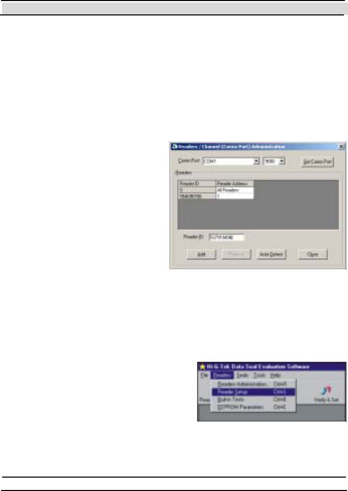
Chapter 7 Evaluation Softw are
- 90 - Hi-G-Tek Ltd. Micro elec tro nics & A sset Tra cking Techno logy
mark it and click on the Remo ve button.
The Evaluation Software assigns a Reader Address to each configured
DataReader automatically.
7.2.2 Setting Up the Communication Port
In the Readers Administration window, click on the Comm. Port drop
down list to define the
communication port that the
DataReaders are connected to.
Click on the Baud Rate drop
down list t o t he right of the
Comm. Port drop down list to
define t he baud rat e of t hat port .
Once you have made your
selection, click on the Set C omm
Port button. Figure 7-0 shows the
Reade rs Administration
window.
7.3 Reader Setup
The Reader Se tup window allows you to view and to modify the
parameters of the DataReaders. A complete description of each parameter
is given in chapter 8.
To open the Reader Setup window,
click on the Reader Setup icon in the
toolbar or select the Rea de rs menu and
then the Re ader Setup item as shown in
Figure 7-0.
Figure 7-0
Figure 7-0
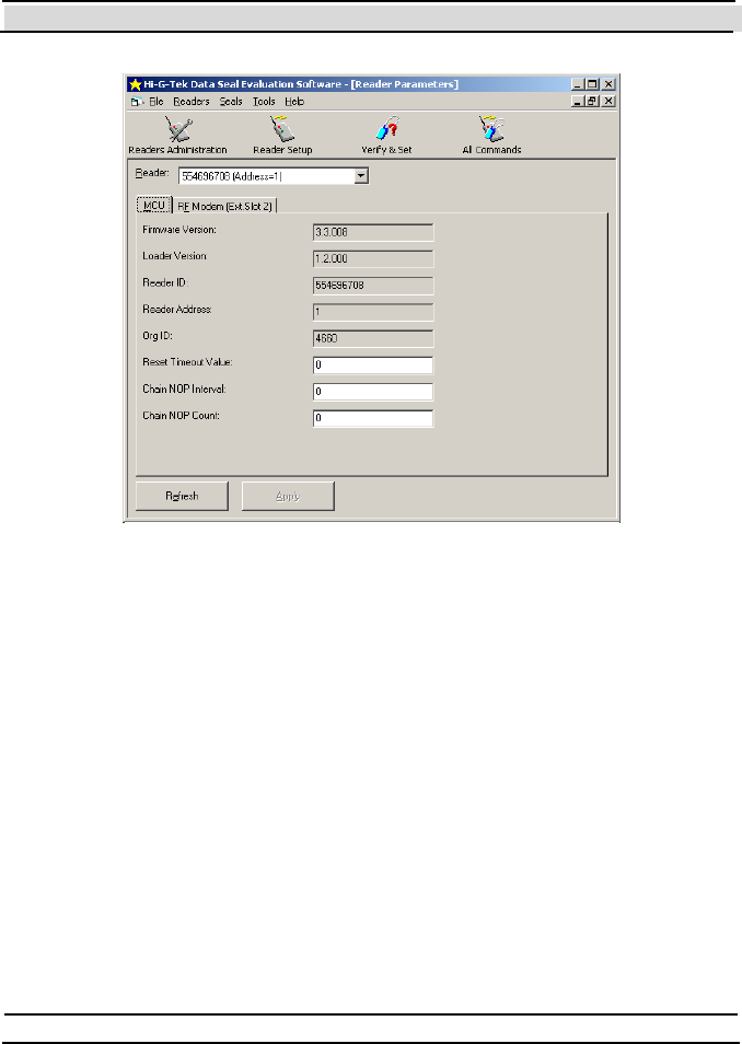
Chapter 7 Evaluation Softw are
Hi-G-Tek Ltd. Micro electro nics & Asset Tracking Technology - 91 -
The parameters of the DataReader are divided into 2 groups: MCU and RF
Modem. Each group has its own tab in the Rea de r Setu p window. Some
parameters are read-only. These parameters appear over a grey background
(like the Firmware Version parameter in Figure 7-0)
If you want to change the value of one or more parameters, enter the new
value(s) in their corresponding text boxes, and then click Apply to write
the new values to the DataReader. To read the current values from the
DataReader click on the Ref resh butt on.
7.4 The Verify and Set Window
The Ve rify and Set window contains the most useful commands in a way
that is easy to use.
Figure 7-0
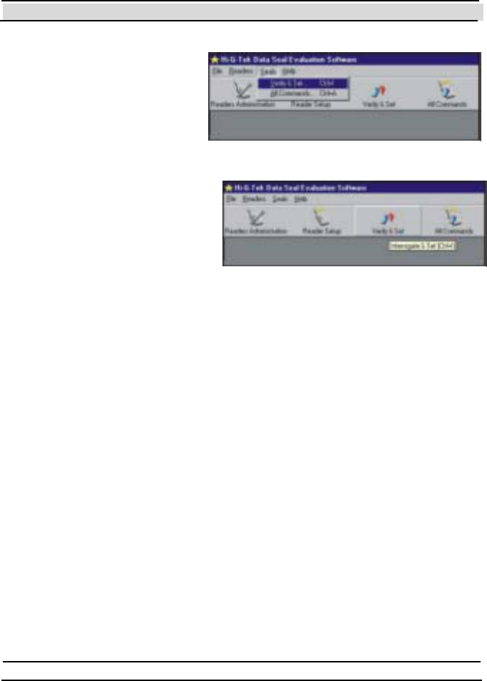
Chapter 7 Evaluation Softw are
- 92 - Hi-G-Tek Ltd. Micro elec tro nics & A sset Tra cking Techno logy
You can access the Ve rify and Set window by clicking the Seals menu
button on the top of the
screen , an d th en on Ve ri fy
and Set as shown in Figure 7
-0 . Alternatively, you can
click on the Ve ri fy & Set
icon as shown in Figure 7-0
or press Ctrl+I.
Figure 7-0 shows the various
parts of the window. Following
are the descriptions of these
parts: Figure 7-0
Figure 7-0
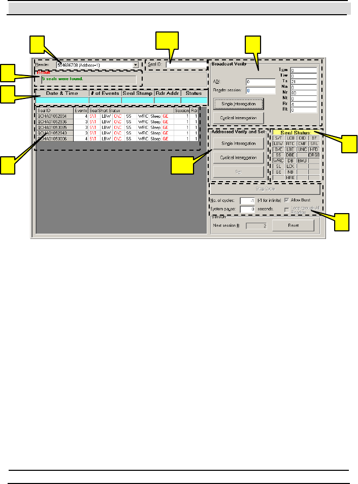
Chapter 7 Evaluation Softw are
Hi-G-Tek Ltd. Micro electro nics & Asset Tracking Technology - 93 -
1. Reader ID selection box: In this box, you can choose which
DataReader will invoke the commands.
2. Broadcast (normal) Verify frame: Through this frame you can invoke
the Ve ri fy command as well as to control some of its parameters.
3a. Addressed Verify and Set frame: T hrough this frame you can invoke
the Addresse d Verify command and the Se t command.
3b. Seal ID box: In this box you have to specify the Seal ID with which
you want to communicate using the Addresse d Verify and the Se t
commands. A Seal ID can also be entered to this box by clicking on the
desired Seal ID in the Broadcast Verify responses list (Item #8)
4. Result indication box: After invoking any of the commands, this box
indicates whether the command succeeded or failed. Success
indications appear in green, while failure indications appear in red. In
1 2
3a
3b
4
5
6
7
8
Figure 7-0

Chapter 7 Evaluation Softw are
- 94 - Hi-G-Tek Ltd. Micro elec tro nics & A sset Tra cking Techno logy
some cases of failure more detailed information about the cause of the
failure can be seen by hovering with the mouse cursor over this box.
5. Addressed Verify response indicators: When a DataSeal responds to an
Addressed Ve rify command, these indicators display the information
that was received by it. Its Long Status is displayed in the Seal Status
indicators (Item #6)
6. Seal Status indicators: When a DataSeal responds to an Addressed
Verify command, these indicators reflect the DataSeal's Long Status
as reported by the DataSeal. Flags that are set appear in red, while
unset flags remain black. When a DataSeal responds to a Se t command,
only the Short Status is returned and is indicated by the leftmost
column. The rest 3 columns are dimmed. A complete list of the
DataSeal's Long Status flags and their meanings appear in chapter 8.
7. Broadcast Verify responses list: After a Broadcast Verify interrogation,
the responses of the DataSeals are added to this list.
8. Cyclical interrogations control frame: T his frame contains some
controls that you can use to affect the way that a cyclical interrogation
(Broadcast or Addressed) is executed.
7.4.1 Executing Broadcast Verify Command
The B ro a dcas t Ve ri fy command (sometimes referred to simply as Ve rify)
is a command that collects information from all the DataSeals that receive
the command (given that their OrgID, Department and ADI match). This
command is the most powerful command, and has many parameters that
enable to fine tune its behavior. A complete description of all the
parameters is given in chapter 8. Normally, the default values of the
parameters are adequate, but you may change them to best suit your needs.
If you want to execute the B ro a dcas t Ve ri fy command only once, click on
the Single Inte rrogation butt on (shown in Figure 7-0). You can also
execute the Broadcast Ve ri fy command continuously (or cyclically) by
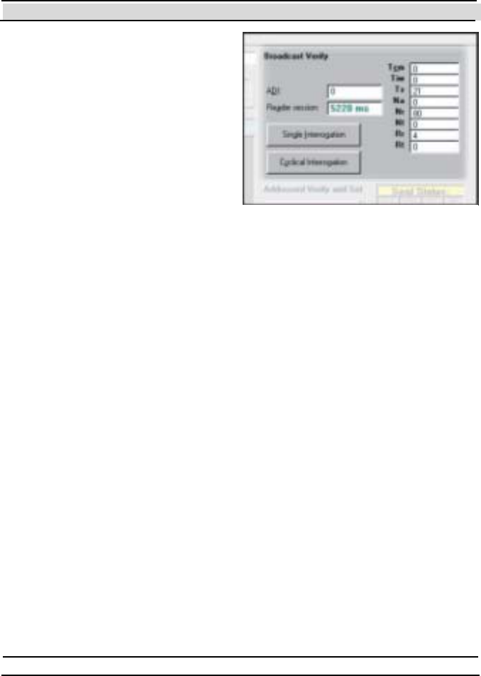
Chapter 7 Evaluation Softw are
Hi-G-Tek Ltd. Micro electro nics & Asset Tracking Technology - 95 -
clicking the Cyclical Interrogation
but ton. You can control some
aspects of the cyclical interrogation
from the cyclical interrogations
control frame (item #8 in Figure
7-0) as described in section 7.4.4.
The results (responses) of the
Broadcast Ve rify command are
displayed in the Broadcast Verify
responses list (it em #7 in Figure
7-0). The results are always
appended to this list. To clear the list click on the Rese t but ton on t he lower
right side of the window.
Each response in the Broadcast Verify responses list contains the following
information:
Seal ID
Events: The number of Event records that exist in the DataSeal.
Seal Short Status: This column is divided into 7 sub columns, each
represents a single flag in the DataSeal's Short Status. If the flag is set
(on), the flag appears red, and if unset (off) the flag appears black. T he
flags are:
• S/T – Set/Tampered: if on, indicates that the DataSeal was
tampered.
• LBW – Low Batt ery W arning.
• O/C – Open/Close: if on, indicates that the Sealing Wire is open.
• SS – Suspended Set: if on, indicates that the DataSeal is in
Suspended Set stat e.
Figure 7-0

Chapter 7 Evaluation Softw are
- 96 - Hi-G-Tek Ltd. Micro elec tro nics & A sset Tra cking Techno logy
• WRC – Wire Resistance Changed: indicates that an attempt to
short circuit the Sealing Wire was detected.
• Sleep – If on, indicates that the DataSeal is in Deep-Sleep mode.
• GE – General Error: if this flag is on, it indicates a problem that
can be determined by other flags in the DataSeal's Long Status,
t hat are not included in t he Short Status.
• Session: This column displays the sequential number of the session
(interrogation). This number is increased with each new Verify
command. This paramet er is added by the Evaluat ion Soft ware, and
is not part of the DataSeal's response.
• Rdr (Reader): The Reader Address of the DataReader that executed
t he command. T his paramet er is added by t he Evaluat ion Soft ware,
and is not part of the DataSeal's response.
You can sort the list using any of the following columns by clicking on the
title of that column: Seal ID, Events, Session and Reader.
The content of the Broadcast Verify responses list can be saved to a tabbed-
delimited text file (Seals.txt), by choosing Save to Seals.txt from the File
menu. After saving the file, you'll be given the possibility to view the file
(if a correct version of Microsoft Excel is installed, the file will be viewe d
using Excel, otherwise it will be viewed using Notepad).
7.4.2 Executing Addressed Verify Comm and
The Addresse d Verify command is similar to the B roa dca st Ve ri f y
command except that it addresses only one specified DataSeal, instead of
all the DataSeals that receive the command.
In order to execute an Addresse d Ve rify command, you must first specify
the Seal ID of the DataSeal you want to interrogate. You do it by typing the
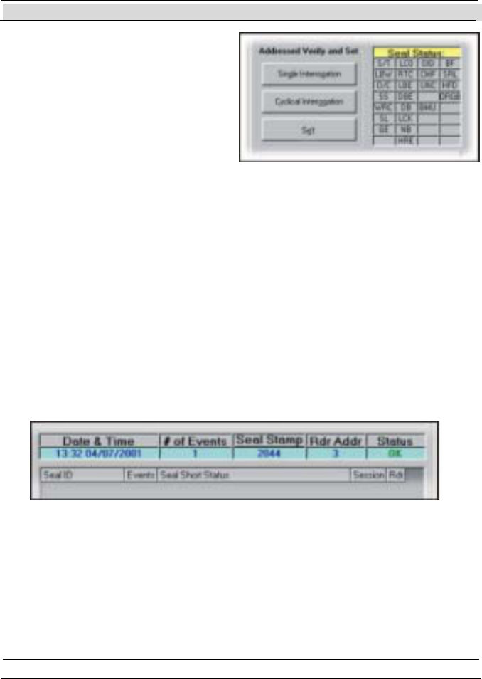
Chapter 7 Evaluation Softw are
Hi-G-Tek Ltd. Micro electro nics & Asset Tracking Technology - 97 -
Seal ID into the Seal ID box (Item
#3b in Figure 7-0). Another option
is to select the Seal ID from the
Broadcast Verify responses list
(It em #7 in Figure 7-0), if it
previously responses to B roadcas t
Verify.
As in the B roadcas t Ve ri fy frame,
here you also have the Single
Interrogation and t h e Cy cli cal Inte rrogati on options: clicking the Single
Interrogation button will execute the Addresse d Verify command only
once, while clicking the Cyclical Interrogation button will execute the
Addressed Ve rify command cyclically according to the options that are
selected in the Cyclical Interrogations control frame (Item #8 in Figure 7-0)
as described in section 7.4.4.
The result (response) of the Addresse d Ve rify is displayed in the
Addresse d Verify response indicat ors (It em #5 in Figure 7-0) and in t he
Seal St at us indicat ors (It em #6 in Figure 7-0).
The Addressed Ve ri fy response indicators contains the following fields:
Data & Time – The current date and time in UTC (GMT) as returned
by the DataSeal.
Figure 7-0
Figure 7-0

Chapter 7 Evaluation Softw are
- 98 - Hi-G-Tek Ltd. Micro elec tro nics & A sset Tra cking Techno logy
# of Events – The number of Event records that are written in the
DataSeal.
Seal Stamp – The value of the Seal Stamp parameter of the DataSeal.
This parameter is a random number that is generated on each open and
close.
Rdr Addr (Reader Address) – T he Reader Address of the DataReader
t hat execut ed the command. This field is added by the Evaluat ion
Software and is not part of the DataSeal's response.
Status – OK or Tampered.
In addition to these indicators, the Seal Status indicators also indicates the
DataSeal's Long Status. Flags that are set appear in red, while unset flags
appear black. For a complete list of the flags in the DataSeal's Long Status,
and their meanings see chapter 0 8.
If the DataSeal didn't respond to the Addre ssed Ve ri fy co mm an d, t h e
Result indicat ion box (It em #4 in Figure 7-0) displays a red message "Seal
does not respond".
7.4.3 Executing Set Command
The Set command is used to prepare a DataSeal for a new use. T he Se t
command is addressed to a specific DataSeal (in fact, it can be addressed to
up to 8 Dat aSeals simult aneously, but the Evaluat ion Soft ware does not
support it through this window). In order to execute a Set command you
must first specify the DataSeal you want to send the command to in the
Seal ID box (It em #3b in Figure 7-0). You can do it also by selecting it
from the Broadcast Verify responses list (It em #8 in Figure 7-0) if it
ap p ears t h er e.
The Sealing Wire must be close in order for the Set command to succeed.
The result of the command is indicated using the Addressed Verify
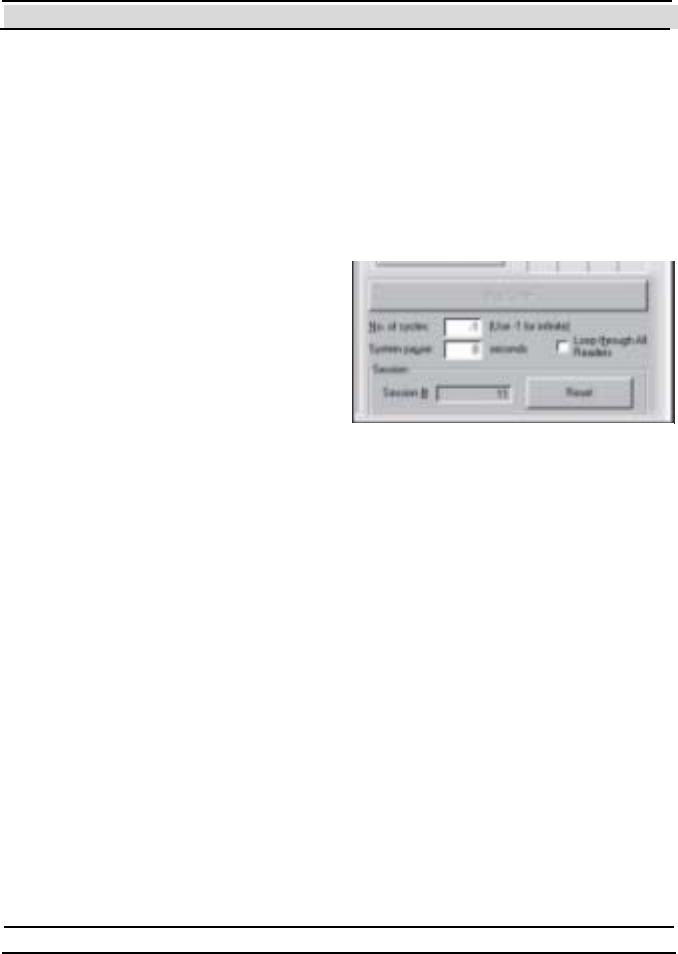
Chapter 7 Evaluation Softw are
Hi-G-Tek Ltd. Micro electro nics & Asset Tracking Technology - 99 -
command indicators and the Seal Long Status indicators (Items #5 and #6
in Figure 7-0).
7.4.4 Cyclical Interrogations Options
The Cyclical Interrogations control frame (Figure 7 -0 ) cont ains some
options that allow you a variety of ways to execute cyclical interrogations.
In the No. of cycles box you can
enter the number of cycles that will
be executed. If you enter "-1", the
Evaluation Software will execute
interrogations until you click on the
Stop Cycle butt on. Even if No. of
cycles is not "-1", you can click on
the Stop Cycle button to stop the
interrogations.
In the System Pause field you can specify the pause between one
interrogation to the next in seconds.
The Loop through all Readers check box is available if more than 1
DataReader is defined. If this check box is checked, the Evaluation
Software will execute the first interrogation using the first DataReader in
the list, the second interrogation using the second DataReader and so on.
After the last DataReader was used, the first one is used again, and so on.
For example, it there are 3 DataReaders, and No . o f cy cles is 8, t he order
that the DataReaders will interrogate will be: 1,2,3,1,2,3,1,2.
The Session # box indicates the sequential number of the interrogation. The
Evaluation Software increases this value with each new interrogation. To
reset this number, and to clear the Broadcast Verify responses list, click the
Reset but ton.
Figure 7-0
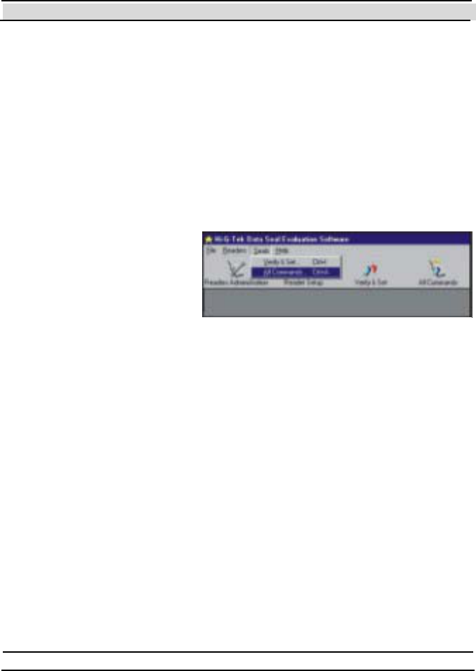
Chapter 7 Evaluation Softw are
- 100 - Hi-G-Tek Ltd. Micro elec tro nics & A sset Tra cking Techno logy
7.5 Executing Any Command using the All Commands
Window
The All Comm an ds window lets you execute any RF command and play
with the "bits and bytes" of the RF protocol. Normally, when a software
programmer writes an application, he doesn't have to play with the bits and
bytes, because the DataSealLib software library (COM DLL) provides
higher level interfaces, but acquaintance with the bits and bytes can be very
helpful sometimes. Also, this is the only place in the Evaluation Software
that you can execute all the RF commands.
To access the All Comman ds
window, choose the All
Commands item from the
Se als menu as shown in
Figure 7-0. Alternatively,
click on the All Comman ds
icon or press Ctrl+A. Figure 7-0
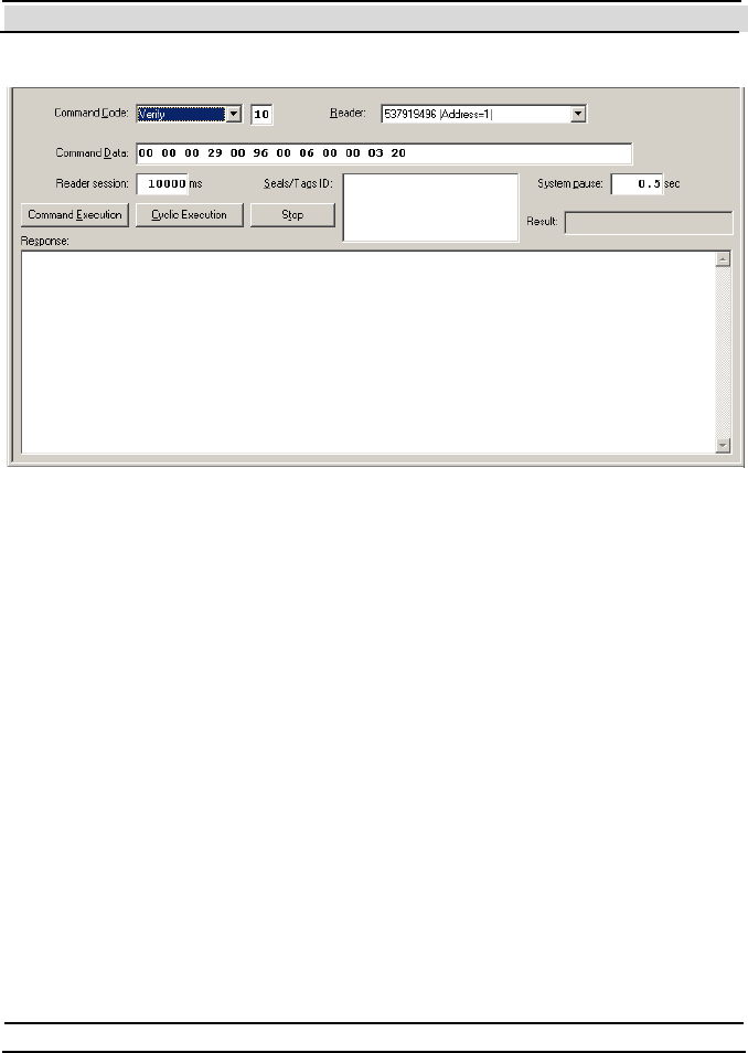
Chapter 7 Evaluation Softw are
Hi-G-Tek Ltd. Micro electro nics & Asset Tracking Technology - 101 -
7.5.1 Executing an RF Comm and
To execute an RF command do the following:
1. Select the command from the Command Code drop down list . T he
code of the command will be displayed to the right of the drop down
list, and the Command Data field will be filled by the default
parameters for that command in hexadecimal format. For commands
that does not have any parameters this field will be empty.
2. You may change the arguments in the Command Data line as desired.
A detailed explanation of each command's structure is the following
sections.
3. Select the DataReader that you want to use from the Reader drop down
list.
Figure 7-0

Chapter 7 Evaluation Softw are
- 102 - Hi-G-Tek Ltd. Micro elec tro nics & A sset Tra cking Techno logy
4. If t he command is an addressed command or mult i-addressed command
(also called BMM List), you have to enter the Seal ID of the DataSeal
or DataSeals that you want to address in the Seals/Tags ID box. To
enter more than one Seal ID, enter each Seal ID on its own line.
5. Click the Command Exe cuti on button.
The results will be displayed in an hexadecimal format in the Re s pon se
box, and for some commands the result will be displayed also as a table or
as text.
You can also execute a command cyclically by clicking the Cyclic
Ex e c uti on button instead of the Command Exe cution but ton. T o stop the
cyclical execution click the Stop butt on. Using t he System Pause field you
can specify the pause in seconds between two interrogations in a cycle.
The Re a de r Ses sion field displays the duration in milliseconds of one
interrogation of the selected command. For some commands you can also
change this value. However, note that specifying lower value than the
default will usually cause an error.
When the command completes, the Re sul t box indicates whether the
command succeeded or failed.
7.6 Specific Comm and Structures
Below is a description of the each one of the RF commands. For each
command its structure (Command Data) is given and also the structure of
t he response. Complet e descript ions of the command argument s are given
in chapter 8.
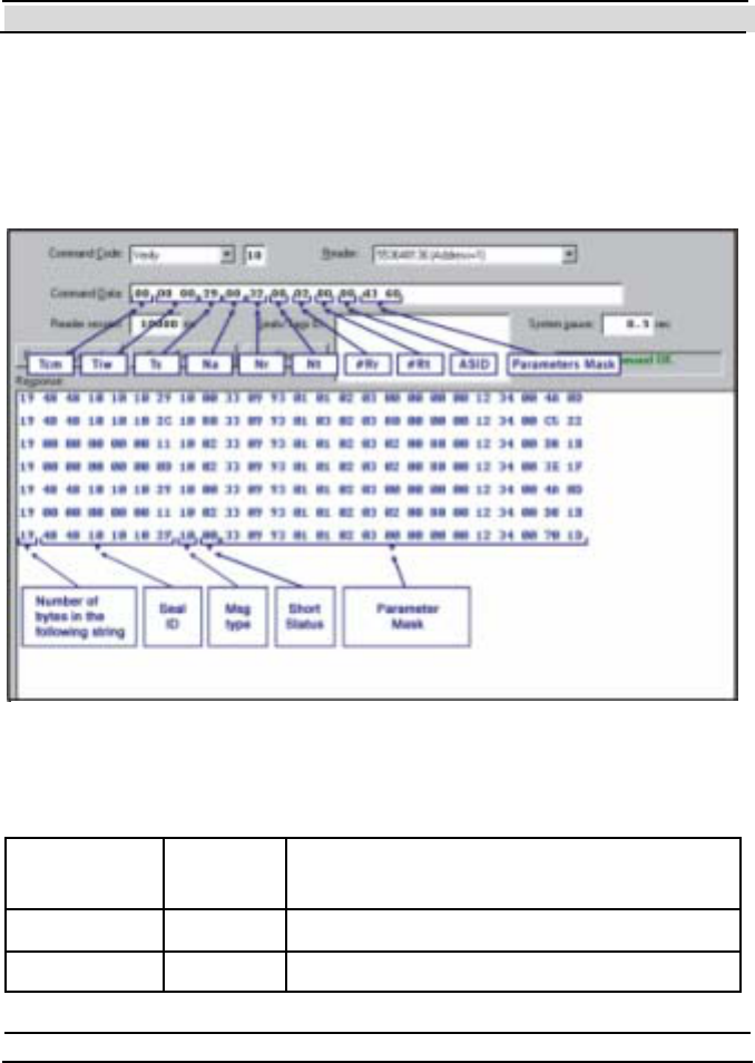
Chapter 7 Evaluation Softw are
Hi-G-Tek Ltd. Micro electro nics & Asset Tracking Technology - 103 -
7.6.1 Verify
The Ve ri f y command is used to seek all the DataSeals located in the
DataReader's Receiving Zone, that their OrgID, Department and ADI
values match those of the DataReader.
The following table explains the most important arguments shown in
Figure 7 -0:
Argument Value in
example
Description
T s 29h (41) Size of response window in milliseconds
Nr 32h (50) Number of response windows
Figure 7-0

Chapter 7 Evaluation Softw are
- 104 - Hi-G-Tek Ltd. Micro elec tro nics & A sset Tra cking Techno logy
Argument Value in
example
Description
#Rr 2 Number of windows that each DataSeal
will chose to respond in.
Mask D360h A bit mask t hat det ermines which
parameters the DataSeal will send in the
resp on se. I n th e ex amp le, t he m ask
contains the following fields: Short Status,
Date & Time, Number of Events,
Firmware Version, Long Status, OrgID
& De partment and Se al Stamp.
In the example, the result contains 7 responses (some of them are from the
same DataSeal). Each response is composed of the following fields:
Fi eld Value in example Description
Number of
byt es
19h (25) The total number of bytes in
the response.
Seal ID 48 48 10 10 10 2F
(IADA01052719)
The Seal ID of the DataSeal
that sent this response.
Msg type 10h (16) The code of the Ve ri fy
command.
Short Status 0
Date & Time 33 09 93 01(hex)
(13/08/2001 9:33)
The DataSeal's internal clock
value (UTC)
Number of
Events
1
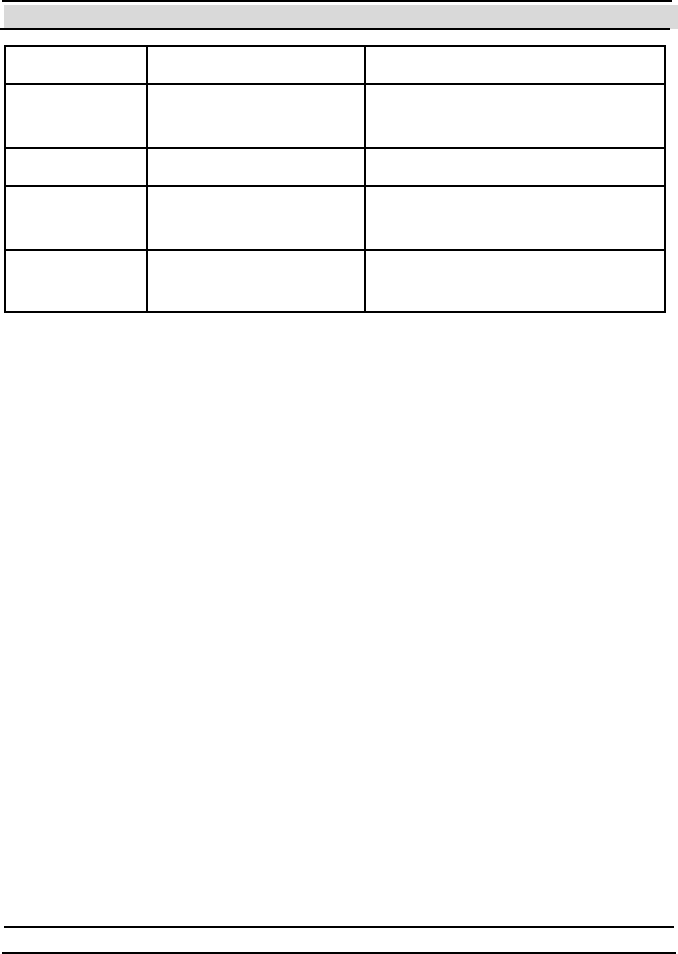
Chapter 7 Evaluation Softw are
Hi-G-Tek Ltd. Micro electro nics & Asset Tracking Technology - 105 -
Fi eld Value in example Description
Firmware
Version
02 03 (hex)
(2.03)
Long Status 00 00 00 00
OrgID &
Department
12 34 00 (hex) OrgID = 4660, Department = 0
Seal Stamp 70 1D (hex)
(28701)
7.6.2 Tampered (Tamper)
The Tampered command is used to find all the DataSeals in the
DataReader’s Receiving Zone which indicate a Tampered st at us. T h e
command parameters and response structure are identical to the Ve ri f y
command.
7.6.3 Addressed Verify
The Addressed Verify command is identical to the Verify command,
except that it is addressed to a specific DataSeal.
This command is an Addressed command, and therefore the Seal ID of the
addressed Dat aSeal has t o be ent ered in the Seal s /Tags ID field before
executing the command.
The arguments of the command are identical to the arguments of the Ve ri f y
command. Note however that there is no use in specifying Rr that is
different than Nr in Addressed Verify, because there are no collisions. Nr
and Rr can be greater than 1 in order to increase the probability of
reception in case of RF interferences.
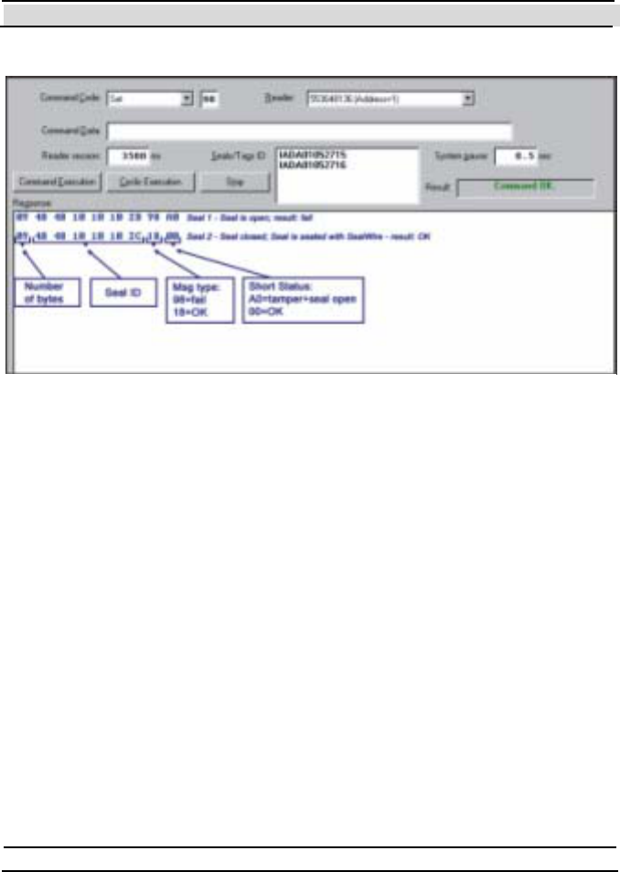
Chapter 7 Evaluation Softw are
- 106 - Hi-G-Tek Ltd. Micro elec tro nics & A sset Tra cking Techno logy
7.6.4 Set
The Se t command is used to prepare a DataSeal for a new use. If the
Sealing Wire is open while the DataSeal receives the command, the
command is not executed. If the Sealing Wire is closed, then all the Event
records are deleted, the Tampered flag is cleared, and a new (first) Event
record is written to indicate the Se t operation.
This command is multi-addressed, and can be sent to up to 8 DataSeals in a
single command. You must enter between 1 and 8 Seal IDs in the
Seals/Tags ID box, one in each line, before executing the command.
The Seal Status in the response indicates whether the command succeeded
or failed: If the Status is OK (closed, not tampered) the command
succeeded, and if it is tampered the command failed. An example of this
can be seen in the Re s pon se box in Figure 7 -0 : the first row indicates an
open Sealing Wire and Tampered state, (the Se t operation failed), while the
second row indicates a closed Sealing Wire and OK state (the Set operation
succeeded).
Figure 7-0

Chapter 7 Evaluation Softw are
Hi-G-Tek Ltd. Micro electro nics & Asset Tracking Technology - 107 -
Note: old DataSeals return only the Short Status as a response to the Set
command (as shown in Figure 7 -0 ), while newer ones (version 2.20 and
above) return Long Status an d Seal S tamp.
7.6.5 Soft Set
Similar to the Se t command, the Soft Set command is used to prepare a
DataSeals for a new use, but unlike the Se t co mm an d, the exist ing Ev en t
records are not deleted. For the description of the response see the Se t
command in the previous section.
This command is multi-addressed, and can be sent to up to 8 DataSeals in a
single command. You must enter between 1 and 8 Seal IDs in the
Seals/Tags ID box, one in each line, before executing the command.
7.6.6 Suspended Set
This command is also similar to the Set command, but unlike the Se t
command, the Sealing Wire can be open, and the operation completes only
afterwards, when the Sealing Wire is closed. Between the command
execution and the closing of the Sealing Wire, the Suspended Set ( SS) f la g
in the Sh ort Status is set. Only when the Sealing Wire is closed, the Event
records are deleted, the Tampered flag is cleared and a new Suspended
Se t Event record is written.
If the Sealing Wire was open at the time of the command execution, the
DataSeal's will indicate the following flags in the Status: Tampered,
Opened, and Suspende d Se t. If the Sealing Wire was closed at the time of
the command execution, the DataSeal will indicate an OK status.
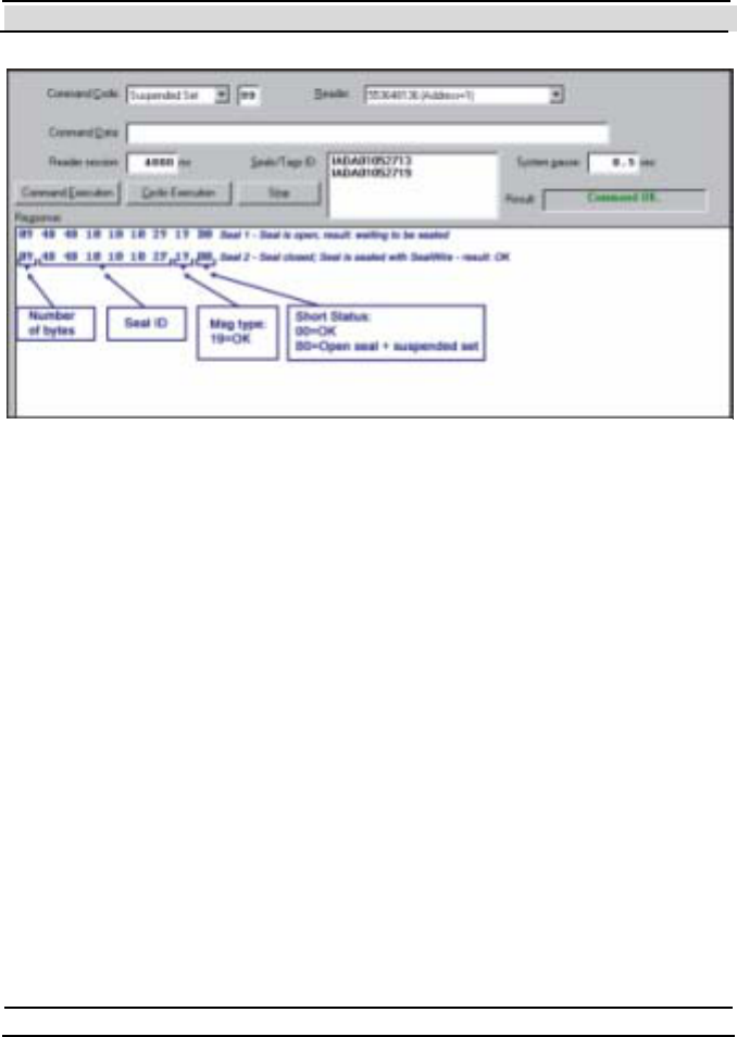
Chapter 7 Evaluation Softw are
- 108 - Hi-G-Tek Ltd. Micro elec tro nics & A sset Tra cking Techno logy
This command is multi-addressed, and can be sent to up to 8 DataSeals in a
single command. You must enter between 1 and 8 Seal IDs in the
Seals/Tags ID box, one in each line, before executing the command.
7.6.7 Read Data
The Re a d Da ta command reads data from the User Data memory of the
DataSeal.
The Evaluat ion Software displays t he result of t his command bot h in
hexadecimal and ASCII formats.
The largest block size that can be read in one session is 67 bytes.
If the arguments of the command are invalid, or the DataSeal can't perform
t he command due t o any other reason, it responds wit h message t ype E3
(hex).
Figure 7-0
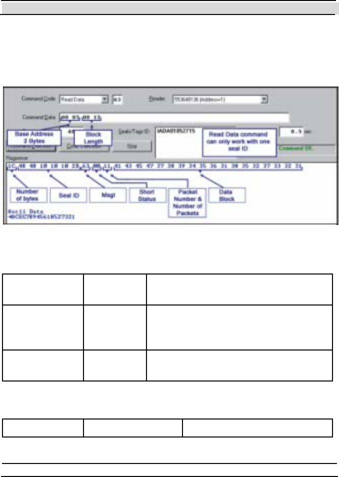
Chapter 7 Evaluation Softw are
Hi-G-Tek Ltd. Micro electro nics & Asset Tracking Technology - 109 -
This command is an Addressed command, and therefore the Seal ID of the
addressed Dat aSeal has t o be ent ered in the Seal s /Tags ID field before
executing the command.
The Command Data is composed of the following arguments:
Argument Value in
example
Description
Address
(2 bytes)
5 The address of the block of data in the
DataSeal's memory that you want to
read.
Block Length
(2 bytes)
12h (18) The length in bytes of the block of data
t hat you want to Read.
The response is composed of the following fields:
Fi eld Value in example Description
Figure 7-0
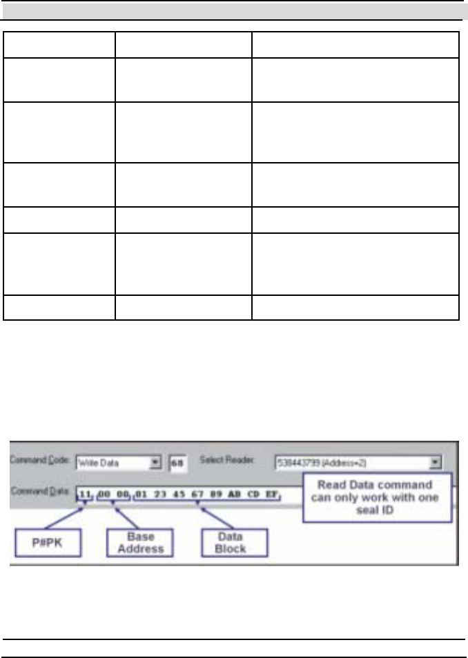
Chapter 7 Evaluation Softw are
- 110 - Hi-G-Tek Ltd. Micro elec tro nics & A sset Tra cking Techno logy
Fi eld Value in example Description
Number of
byt es
1Ch (28) The total number of bytes in
the response.
Seal ID 48 48 10 10 10 2B
(hex)
(IADA01052715)
The Seal ID of the DataSeal
that sent this response.
Msg type 63h The code of the Read Data
command.
Short Status 0
P ack et /# o f
P ack et s
11h (1 of 1) The first nibble is the packet
number, the 2nd is the total
number of packets.
User Data … The requested data.
7.6.8 Write Data
The Write Data command writes a block of data into the User Data
memory in the DataSeal.
Figure 7-0

Chapter 7 Evaluation Softw are
Hi-G-Tek Ltd. Micro electro nics & Asset Tracking Technology - 111 -
The largest block size that can be written in one session is 67 bytes.
If the parameters of the command are invalid, or the DataSeal can't perform
t he command due t o any other reason, it responds wit h message t ype E8
(hex).
This command is an Addressed command, and therefore the Seal ID of the
addressed Dat aSeal has t o be ent ered in the Seal s /Tags ID field before
executing the command.
The Command Data is composed of the following arguments:
Argument Value in
example
Description
P/#PK 11h Packet number out of total number of
packets. At this stage this argument is
not in use and must be 11h.
Base Address 0 The address in the DataSeal's User
Data memory to where you want to
write the data.
Data (All the
rest)
The data to write to the DataSeal's User
Data memory. This field can have any
length up to 67.
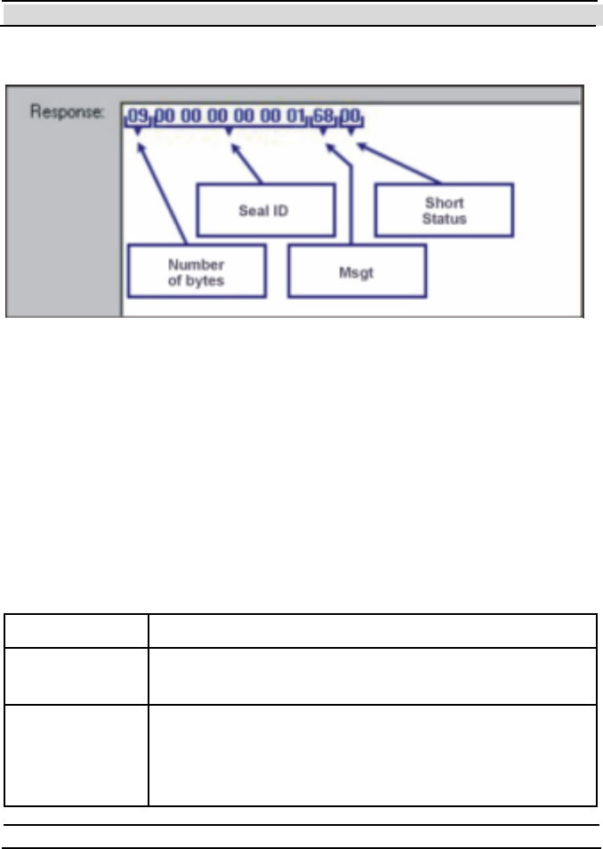
Chapter 7 Evaluation Softw are
- 112 - Hi-G-Tek Ltd. Micro elec tro nics & A sset Tra cking Techno logy
The response data is shown in Figure 7 -0.
7.6.9 Read Parameters
The Re a d Pa ramete rs command uses to read the values of selected
Parameters of a DataSeal.
This command is an Addressed command, and therefore the Seal ID of the
addressed Dat aSeal has t o be ent ered in the Seal s /Tags ID field before
executing the command.
The Command Data is composed of the following arguments:
Argument Description
P/#PK Packet number out of total number of packets. At this
st age t his argument is not in use and must be 11h.
Parameter
codes
This argument can contain a list of the codes of the
Parameters that you want to read. Each Parameter
code is 1 byte. A complete list of the DataSeal
P arameters and t heir codes can be found in chapt er 8.
Figure 7-0

Chapter 7 Evaluation Softw are
Hi-G-Tek Ltd. Micro electro nics & Asset Tracking Technology - 113 -
The response is composed of the following fields:
Field Description
Number of
byt es
The total number of bytes in the response.
Seal ID The Seal ID of the DataSeal that sent this response.
Msg type The code of the Read Parameters command (64h)
Short Status
P ack et /# o f
P ack et s
The first nibble is the packet number, the 2nd is the
total number of packets.
Parameter
codes and
values
This field is a list of pairs of codes and values. Each
pair corresponds to one Parameter that was requested
in the Command Data and is composed from 1 byte of
the code of the Parameter and then the value of the
Parameter. The size of the value of the Parameter
depends on the P arameter it self and can be found in
the list of the DataSeal Parameters in chapter 8.
7.6.10 Write Parameters
The Write Parameters command writes new values for specified
Parameters of the a DataSeal.
You can write new values for multiple Parameters in one Write
Parameters command. Note that some Parameters in the DataSeal are read
only and cannot be written. In this case, and in any other case of failure, the
DataSeal will respond with the Message Type E9 (hex).
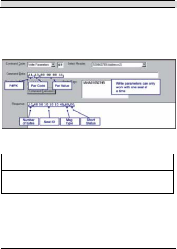
Chapter 7 Evaluation Softw are
- 114 - Hi-G-Tek Ltd. Micro elec tro nics & A sset Tra cking Techno logy
This command is an Addressed command, and therefore the Seal ID of the
addressed Dat aSeal has t o be ent ered in the Seal s /Tags ID field before
executing the command.
The example in Figure 7-0 updates the ADI parameter of the DataSeal to
11h.
The Command Data is composed of the following arguments:
Argument Value in
example
Description
P/#PK 11h Packet number out of total number of
packets. At this stage this argument
is not in use and must be 11h.
Figure 7-0

Chapter 7 Evaluation Softw are
Hi-G-Tek Ltd. Micro electro nics & Asset Tracking Technology - 115 -
Argument Value in
example
Description
Parameters'
codes and
values
13h (The code
of the ADI
parameter),
00 00 00 11h
(new value)
This argument can contain a list of
pairs of Parameters codes and their
new values that you want to write.
Each P aramet er code is 1 byte,
followed by t he value that you want
to write to that Parameter. The size
of the value depends on the
P arameter it self and can be found in
the list of the DataSeal Parameters in
chapter 8.
The response is composed of the following fields:
Field Description
Number of
byt es
The total number of bytes in the response.
Seal ID The Seal ID of the DataSeal that sent this response.
Msg t ype The code of t he Re a d P a rame te rs command (64h)
Short Status
7.6.11 Reset Data
The Reset Data command erases all the User Data area and initialize it to
0s.
This command is multi-addressed, and can be sent to up to 8 DataSeals in a
single command. You must enter between 1 and 8 Seal IDs in the
Seals/Tags ID box, one in each line, before executing the command.
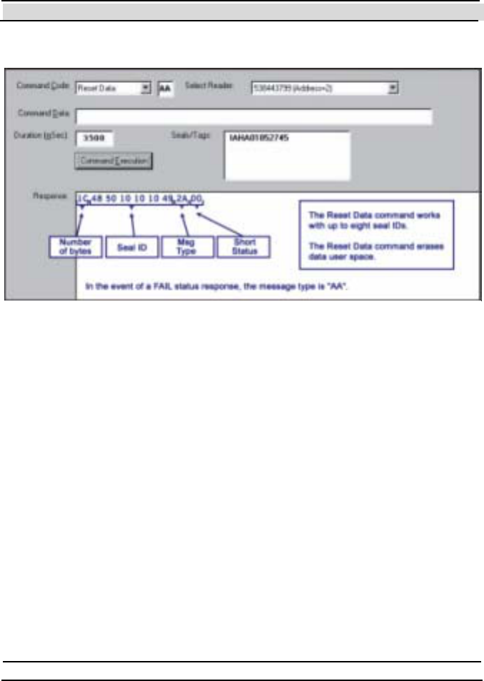
Chapter 7 Evaluation Softw are
- 116 - Hi-G-Tek Ltd. Micro elec tro nics & A sset Tra cking Techno logy
The command has no arguments, and the response is shown in Figure 7 -0.
7.6.12 Deep Sleep
The Deep Sleep command puts DataSeals in Deep Sleep mode.
Figure 7-0
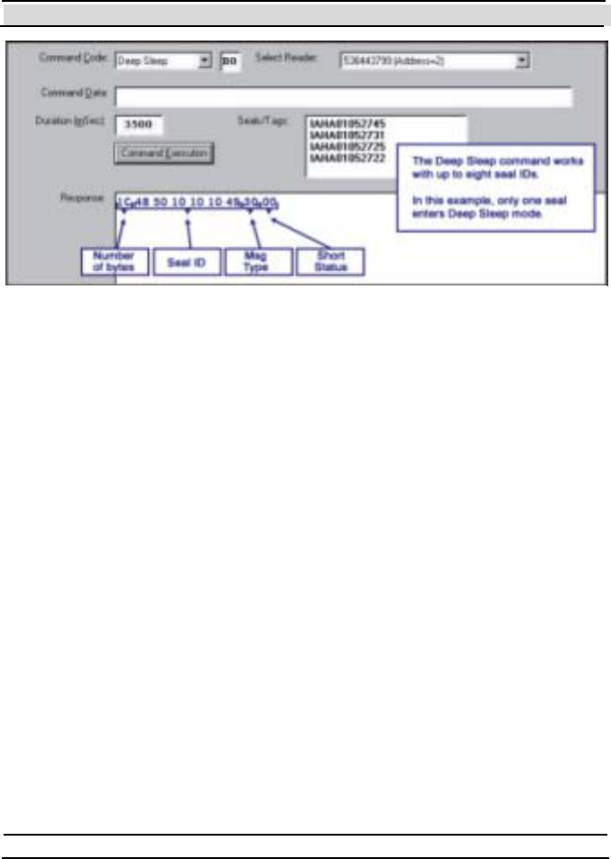
Chapter 7 Evaluation Softw are
Hi-G-Tek Ltd. Micro electro nics & Asset Tracking Technology - 117 -
This command is multi-addressed, and can be sent to up to 8 DataSeals in a
single command. You must enter between 1 and 8 Seal IDs in the
Seals/Tags ID box, one in each line, before executing the command.
7.6.13 Hard Wakeup
This command returns DataSeals from Deep Sleep mode into normal
operation mode.
This command is multi-addressed, and can be sent to up to 8 DataSeals in a
single command. You must enter between 1 and 8 Seal IDs in the
Seals/Tags ID box, one in each line, before executing the command.
Figure 7-0
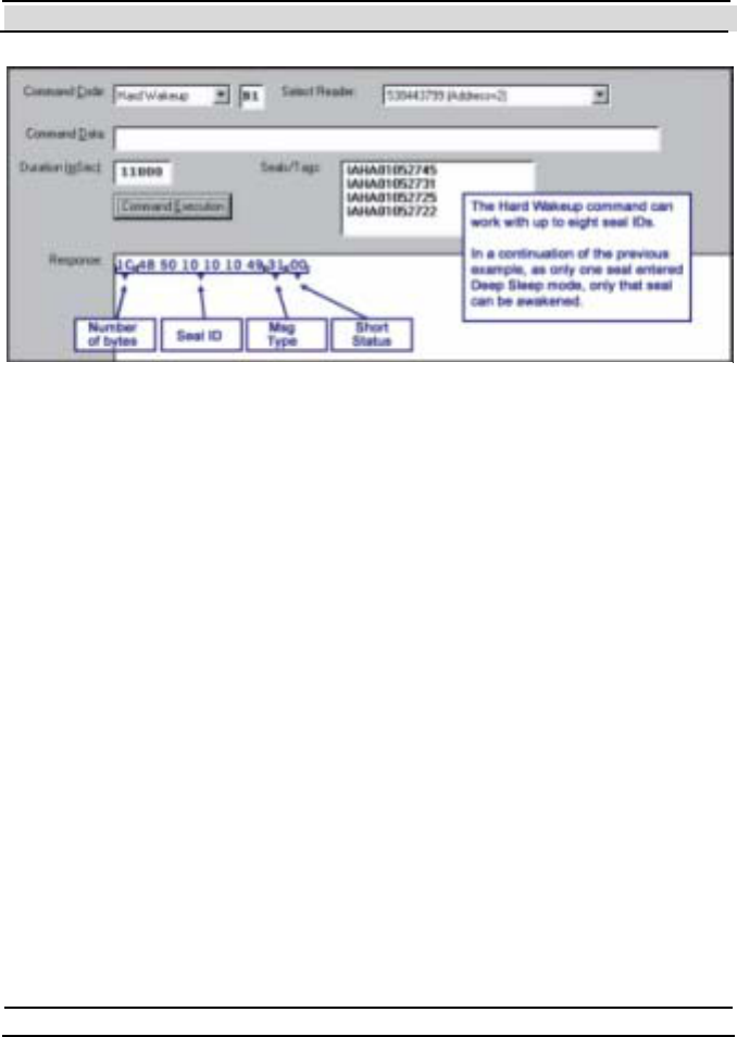
Chapter 7 Evaluation Softw are
- 118 - Hi-G-Tek Ltd. Micro elec tro nics & A sset Tra cking Techno logy
7.6.14 Start Alert Burst Mode
The Start Alert Burst Mode command puts the DataSeal into Alert Burst
mode. In this mode, whenever the DataSeal is opened, it transmits a
message that the DataReaders can receive to report the event.
The number of transmissions, the pause between then, and the data that will
be sent with it can be configured using some DataSeal Parameters. See
chapter 8 for a detailed descriptions of the DataSeal Parameters.
This command is multi-addressed, and can be sent to up to 8 DataSeals in a
single command. You must enter between 1 and 8 Seal IDs in the
Seals/Tags ID box, one in each line, before executing the command.
Figure 7-0
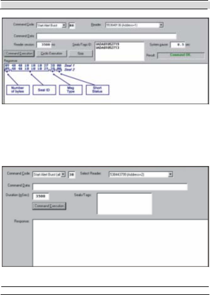
Chapter 7 Evaluation Softw are
Hi-G-Tek Ltd. Micro electro nics & Asset Tracking Technology - 119 -
7.6.15 Start Alert Burst Mode (all)
This command is similar to the Start Alert Burst Mode command, except
that it is a broadcast command instead of a multi-addressed command. In
Figure 7-1
Figure 7-1
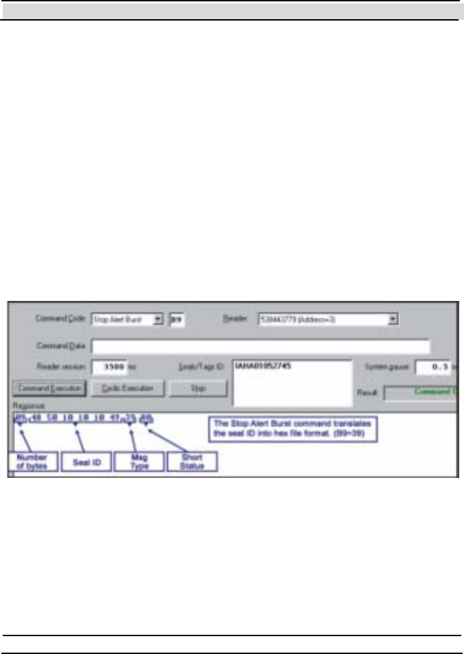
Chapter 7 Evaluation Softw are
- 120 - Hi-G-Tek Ltd. Micro elec tro nics & A sset Tra cking Techno logy
other words, all the DataSeals that receive this command enter into Alert
Burst mode.
This command does not have any arguments, and the receiving DataSeals
don't send any response to this command.
7.6.16 Stop Alert Burst Mode
The Stop Alert Burst Mode command stops the DataSeal from working in
Alert Burst mode.
This command is multi-addressed, and can be sent to up to 8 DataSeals in a
single command. You must enter between 1 and 8 Seal IDs in the
Seals/Tags ID box, one in each line, before executing the command.
7.6.17 Stop Alert Burst Mode (all)
This command is similar to the Start Alert Burst Mode command, except
that it is a broadcast command instead of a multi-addressed command. In
other words, all the DataSeals that receive this command stop being in
Alert Burst mode.
Figure 7-1

Chapter 7 Evaluation Softw are
Hi-G-Tek Ltd. Micro electro nics & Asset Tracking Technology - 121 -
7.6.18 Acknowledge Alert Burst
The Acknowledge Alert Burst command confirms to the DataSeal that its
Burst message has been received. After The DataSeal receives the
Acknowledge Alert Burst command, the DataSeal stops transmitting the
Burst message unt il a new Tampered Event occurs.
Figure 7-1
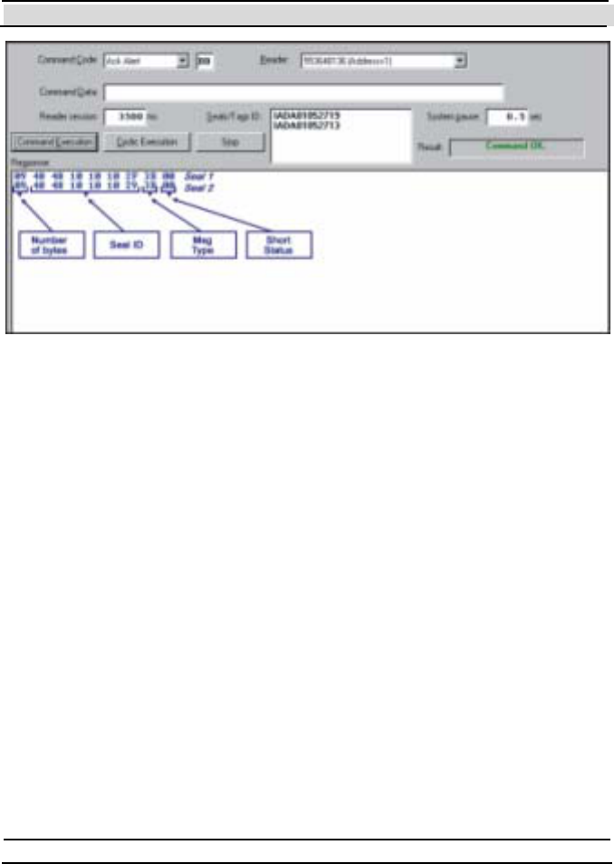
Chapter 7 Evaluation Softw are
- 122 - Hi-G-Tek Ltd. Micro elec tro nics & A sset Tra cking Techno logy
This command is multi-addressed, and can be sent to up to 8 DataSeals in a
single command. You must enter between 1 and 8 Seal IDs in the
Seals/Tags ID box, one in each line, before executing the command.
7.6.19 Read Events
The Re a d Eve nts command reads part or all of the Event records stored in
the DataSeal's Events Memory.
This command is an Addressed command, and therefore the Seal ID of the
addressed Dat aSeal has t o be ent ered in the Seal s /Tags ID field before
executing the command.
Figure 7-1
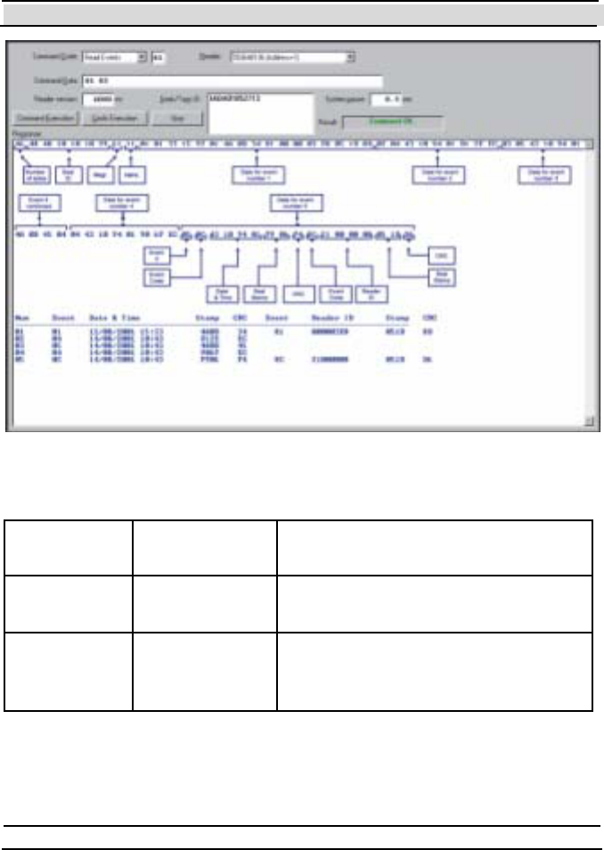
Chapter 7 Evaluation Softw are
Hi-G-Tek Ltd. Micro electro nics & Asset Tracking Technology - 123 -
The Command Data is composed of the following arguments:
Argument Value in
example
Description
First Event
number
1 The sequential number of the first
Event record to read.
Number of
Events to
read
5 The number of Event records to read.
The response is composed of the following fields:
Figure 7-1
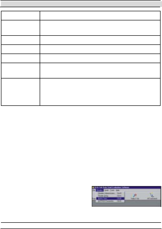
Chapter 7 Evaluation Softw are
- 124 - Hi-G-Tek Ltd. Micro elec tro nics & A sset Tra cking Techno logy
Field Description
Number of
byt es
The total number of bytes in the response.
Seal ID The Seal ID of the DataSeal that sent this response.
Msg t ype The code of t he Re a d P a rame te rs command (64h)
Short Status
P ack et /# o f
P ack et s
The first nibble is the packet number, the 2nd is the
total number of packets.
Event records This field contains all the requested Event records.
Figure 7-1 illustrates the format of the Event records.
A complete description of the Event records is found
in chapter 8.
The Evaluation software displays the Event records also as a table below
the hexadecimal string.
Note that there are 2 kinds of Event records: Short Events (8 bytes) and
Long Events (16 bytes). In Figure 7-1, Event records 1 and 5 are Long
Events, and the rest are Short Events.
7.7 Advanced Features
7.7.1 Built-In Test
The DataReader can perform a self-test
and report it s st at us. In order to perform
the test, open the Te st s window by
clicking on the Rea de rs menu and then
on the Built-In Tests menu item as Figure 7-1
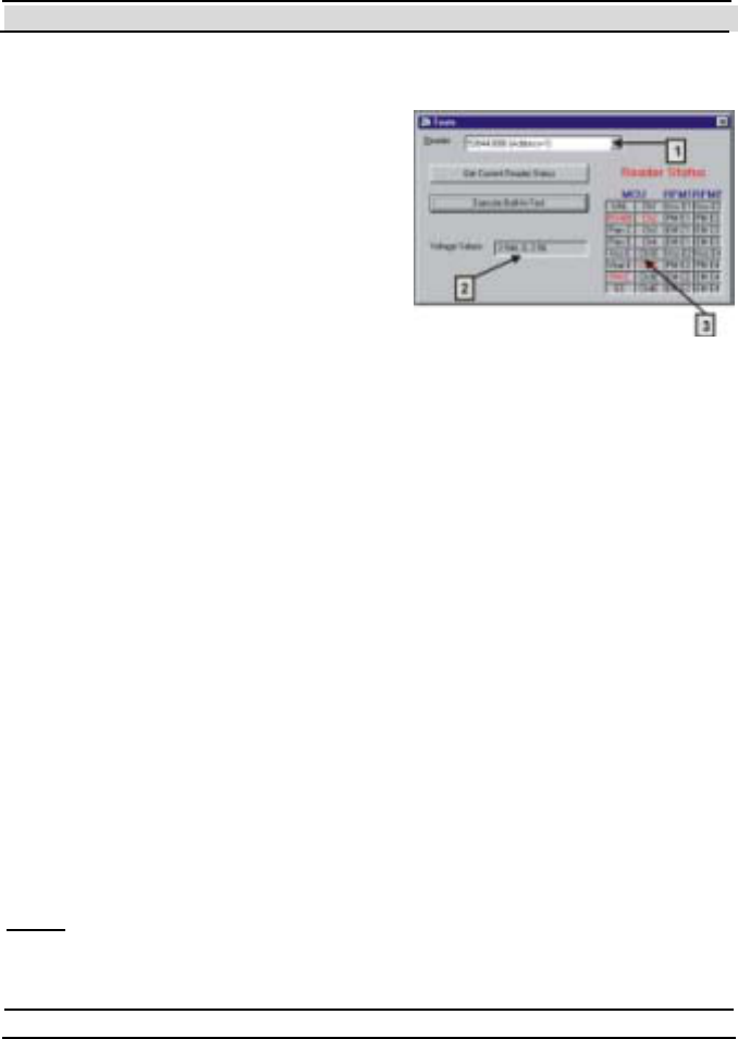
Chapter 7 Evaluation Softw are
Hi-G-Tek Ltd. Micro electro nics & Asset Tracking Technology - 125 -
shown in Figure 7-1.
Figure 7-1 shows the Te s ts window. In
order to perform the built-in test, first
select the DataReader you want to test
from the Rea de r drop down list (It em
#1). Then click on the Execute Built-In
Te s t button. If you only want to get the
results of the last performed test, click
on the Get Current Reader Status
button.
The Vol t age Value s box (Item #2)
displays the actual values measured by the DataReader: The first value
(2.544 in the example) represents the voltage value of the MCU, the second
(0 in the example) represents the voltage value of RF Modem #1 (not
installed) and the third value (2.56 in the example) represents the voltage
value of RF Modem #2.
Item #3 displays the status flags of the DataReader. A flag that is on
appears red, while flags that are off appear black.
7.7.2 Authorization Levels and Passwords
Some feat ures in t he Evaluat ion Soft ware are meant t o be used only by
advanced users or by Hi-G-T ek's dist ributors. To prevent unauthorized
users from accessing the advanced features, the software requires a
password. The software recognizes 3 levels of authorized users: User (the
default ), Administ rat or and Dist ributor. This manual does not cover t he
feat ures that are available only to Dist ribut ors.
Note: The levels of authorization, passwords and log-ins of the Evaluation
Software are completely separate from the user permissions, passwords and
log-ins which are used by the operating system.
Figure 7-1
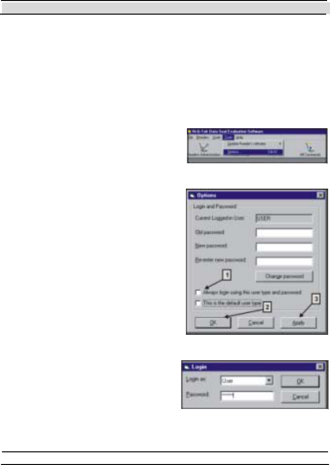
Chapter 7 Evaluation Softw are
- 126 - Hi-G-Tek Ltd. Micro elec tro nics & A sset Tra cking Techno logy
7.7.2.1 Logging-in Using the Desired Authorization Level
After the software is installed, it does not request a password and is
automatically activated using the User authorization level (the lowest). In
order to log in with a different level of authorization, do the following:
Open the Options dialog (shown in Figure 7-1) by choosing Options
from the Tools menu, as shown in Figure 7 -1.
Clear the check box labeled Always
l ogin usi ng th is use r type an d
password (it em #1 in Figure 7-1)
Click OK to close the Options
dialog window.
Restart the Evaluation Software
(exit the software, the run it again).
You should now see the Login
dialog window as shown in Figure 7
-1 . Choose the desired authorization
level from the Lo gi n a s drop down
list, type the appropriate password
in the Password box and click OK.
The Default password for User is empty
(no password), and for Administrator is
"Admin".
7.7.2.2 Changing Passw ords
In order to change a password for a
particular user type (authorization
level), you must be logge d in t o t he
Figure 7-1
Figure 7-1
Figure 7-1

Chapter 7 Evaluation Softw are
Hi-G-Tek Ltd. Micro electro nics & Asset Tracking Technology - 127 -
Evaluat ion Soft ware using t his user type. For example, in order t o change
the Administrator's password you must be logged in as Administrator.
To change the password of the current ly logged in user t ype do t he
following:
Open the Options dialog (shown in Figure 7-1) by choosing Options
from the Tools menu, as shown in Figure 7 -1.
Make sure that the user type that appears in the Current Logged-in
Use r box is the user type to which you wish to change the password. If
it is not, close the options dialog by clicking Cancel, then restart the
Evaluat ion Soft ware and log in using t he user t ype to which you want
to change the password.
Type in the old password in the appropriate box.
Type the new password in the appropriate box.
Type the new password again in the box labeled Re-enter new
password.
Click on the Chan ge Pass word butt on.
If everything went fine (the old password was correct and the 2 new
copies of the new password are equal), an acknowledgment message
box will appear, saying that you must click on Ok or Apply in order to
apply the change.
Click OK to apply the change and to close the dialog window.
7.7.3 Updating the DataReader's Internal Softw are
The DataReader's internal software is composed of 2 modules. These
modules can be updat ed (downloaded t o the DataReader) with newer
versions supplied by Hi-G-Tek when they're available. The Evaluation
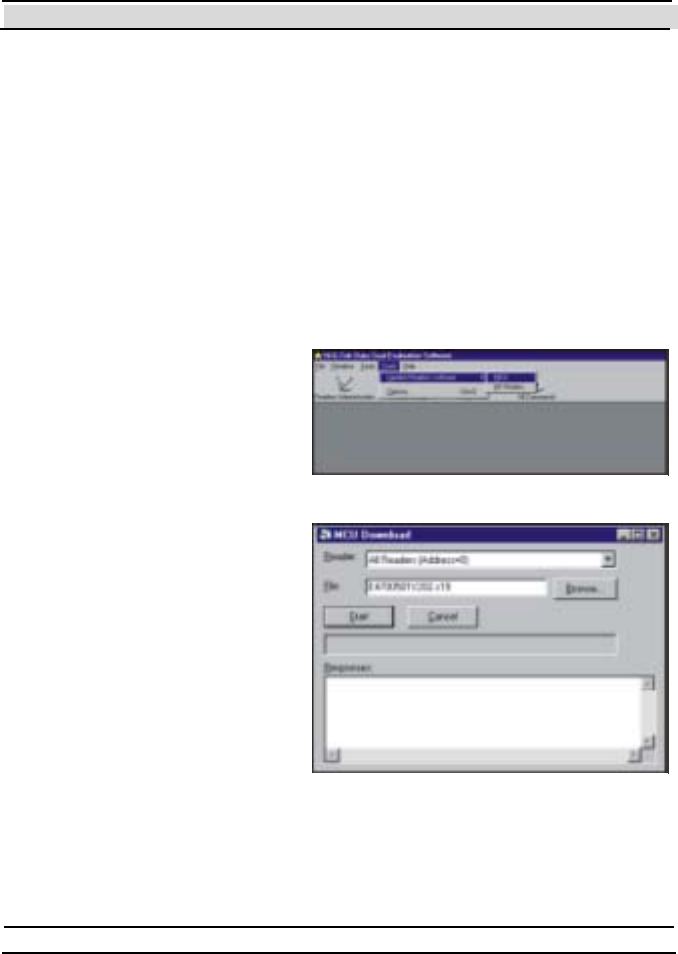
Chapter 7 Evaluation Softw are
- 128 - Hi-G-Tek Ltd. Micro elec tro nics & A sset Tra cking Techno logy
Software includes 2 do wnload utilities to update these 2 modules: T he
MCU Download Utility and the RF Mo dem Do wn lo a d utility.
7.7.3.1 The MCU Dow nload Utility
To update the DataReader's MCU software do the following:
Open the MC U Do wnl oa d window (shown in Figure 7 -1 ) by choosing
the Tools menu, then the Update Reader's Software -> MC U item as
shown in Figure 7 -1.
Select the appropriate Reader ID from the drop down list.
Type the full path and file
name of the updated
software's file, or click
Browse… to select it using
a common file selection
dialog box.
Click Start to start the
download process.
If the download process starts
successfully, a progress bar will
indicate the progress of the
download process. If after 10
seconds the process won't start,
the message shown in Figure 7
-1 will be displayed, letting you
the option to keep trying or to
cancel.
Figure 7-1
Figure 7-1
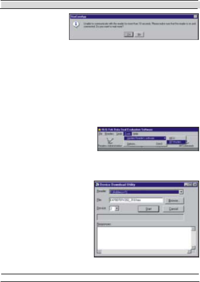
Chapter 7 Evaluation Softw are
Hi-G-Tek Ltd. Micro electro nics & Asset Tracking Technology - 129 -
After the process has
been completed
successfully, an
appropriate message
will appear, and the
DataReader will re-
initialize itself using the new software. T he re-initialization takes about 30
seconds in which the power LED of the DataReader alternates between red
and green, and at the end it should remain green. If it remains red or unlit,
see chapter 0 for troubleshooting.
7.7.3.2 RF Modem Dow nload Utility
To update the DataReader's RF Modem software do the following:
Open the De vi ce Do wnlo a d
Utility window (shown in
Figure 7 -1 ) by choosing the
Tools menu, then the Update
Reader's Software ->RF
Modem item as shown in
Figure 7-1.
Select t he ap prop r iat e
Reader ID from the drop
down list . If t he appropriat e
Reader ID does not appear in
the drop down list, return to
the Re a de rs
Administration window and
add the DataReader as
described in sect ion 7.2.
Type the full path and file
name of the updated
Figure 7-1
Figure 7-1
Figure 7-1

Chapter 7 Evaluation Softw are
- 130 - Hi-G-Tek Ltd. Micro elec tro nics & A sset Tra cking Techno logy
software's file, or click Browse… to select it using a common file
select ion dialog box.
Mak e sur e th at t h e v alue in t h e De vi ce drop down list shows "2".
Click Start to start the download process.
A progress bar will indicate the progress of the download process. During
the process the DataReader's Power LED indicator will be off. After the
process has been completed successfully an appropriate message will
appear, and the DataReader's Power LED indicator will turn green.

Chapter 8 System Parameters and Commands
- 132 - Hi-G-Tek Ltd. Micro elec tro nics & A sset Tra cking Techno logy
8 System Parameters and Commands
This chapter describes the details of the communications with the DataSeal
and the DataReader. Even though Hi-G-Tek publishes the RS-232/485
protocol of the DataReader, and part of the RF protocol, this manual does
not cover these details. Instead, it describes the commands and the
parameters in a more conceptual way, with syntax and examples in Visual
Basic as they can be used through the DataSealLib COM library. Note
there's also an online help that is supplied with the library. This online help
is more technical than the explanations in this chapter: while this chapter
explains the concepts, the online help describes the COM interface in more
details.
8.1 The High Frequency RF Protocol
8.1.1 The Basics
In order to conserve power, the DataSeal is "asleep" most of the time. It
only opens its High-Frequency receiver for a short time every
predetermined period – usually 3 seconds. This fact has some implications
on the RF protocol as explained below.
The interval in which the DataSeal opens its receiver is determined by a
configurable parameter called Tw (which its default value corresponds to
about 3 seconds). Because the DataSeal listens to the RF only in this
intervals, if a DataReader wants to communicate with that DataSeal, it must
transmit a special signal called Reader Interrogation Header, that is at least
in the duration of Tw , in order for the DataSeal to receive it. When the
DataSeal receives this signal (in the short period that its receiver is open), it
knows that a command should follow, and it waits for that command. After
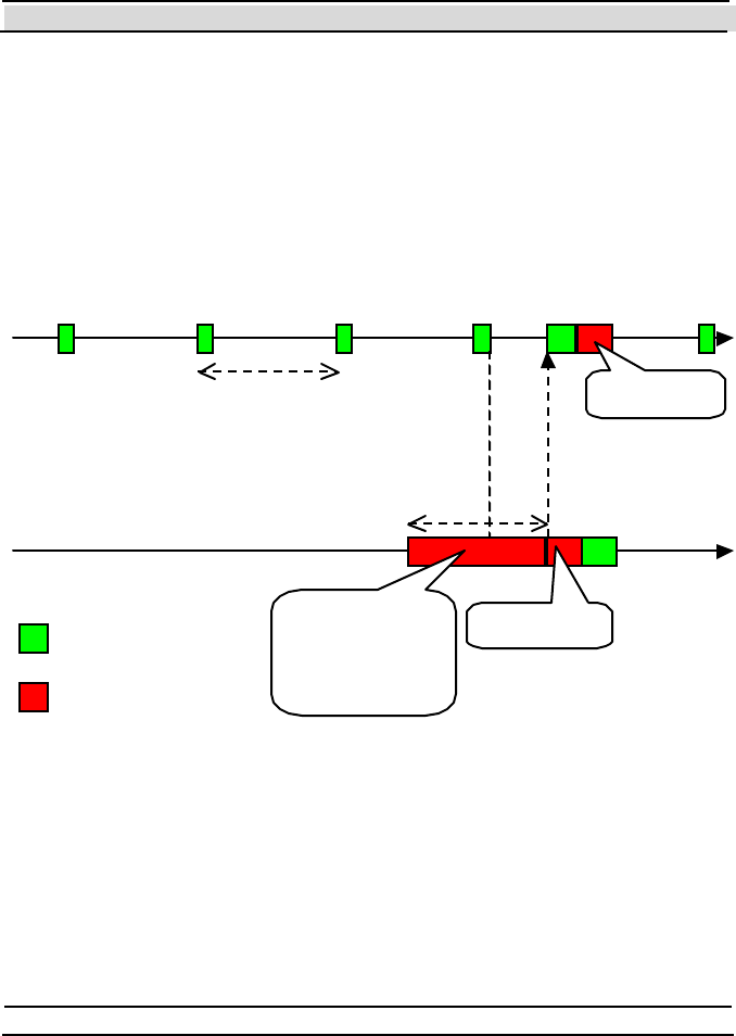
Chapter 8 System Parameters and Commands
Hi-G-Tek Ltd. Micro electro nics & Asset Tracking Technology - 133 -
receiving and performing the command and responding if necessary, it
returns to the state of sleeping and opening the receiver every Tw .
The duration of the Reader Interrogation Header should be 135msec
more than Tw . The DataReader has a configurable parameter called
Th w that determines this period. Note that the DataSeal's Tw
parameter should be configured with the same value for all the
DataSeals, and the corresponding Th w parameter value should be
configured appropriately in all the DataReaders in a given system.
Figure 8-0 demonstrates the concept of the wakeup period and the Reader
Interrogation Header. The upper line represents the time line of the
DataSeal, and the bottom line represents the time line of the DataReader. It
is clear to see from that figure why Th w (the length of the Reader
Interrogation Header) should be just a bit more than the Wakeup Period
(Tw ).
DataSeal
DataReader
- Receive
- Transmit
Wakeup
period
(T w)
Reader
Interrogation
header (Thw =
Tw +135ms
)
Command
Response
Figure 8-0

Chapter 8 System Parameters and Commands
- 134 - Hi-G-Tek Ltd. Micro elec tro nics & A sset Tra cking Techno logy
The Reader Interrogation Header is composed of many short segments that
contain indications of when the command starts. This way, when a
DataSeal receives the Reader Interrogation Header, it doesn't have to keep
its receiver open until the command, rather, it goes to sleep exactly until the
command.
Choosing the best Tw and Th w should take in account the following facts:
Small Tw and Th w will improve response times for RF command. Big
Tw and Th w will cause lengthily interrogations.
Small Tw and Th w will shorten the battery lifetime of the DataSeals.
Big Tw and Th w will lengthen it.
8.1.2 Addressing Types
In general, there are 3 types of commands that are distinguished by the way
they indicate which DataSeal or DataSeals will respond:
1. Addressed (AMM): These commands specify exactly one Seal ID.
Only the DataSeal with that Seal ID responds.
2. Multi Addresse d (BMM List): These commands specify a list of Seal
IDs. The DataSeals in the list respond in the same order as they appear
in the list. This way there are no RF collisions between the responses of
t he different DataSeals. Mult i Addressed commands wit hout argument s
can contain up to 8 Seal IDs in the list. Currently, the only Multi
Addressed command with arguments is the Multi Addresse d Verify,
which can contain up to 7 Seal IDs.
3. Broadcast (BMM): These commands are aimed for all the DataSeals
that receive the DataReader's transmission. There are actually 2 types
of broadcast commands: commands without response and commands
with response. The commands that do not wait for a response from the
DataSeals are the simplest, in the way that after the DataReader has

Chapter 8 System Parameters and Commands
Hi-G-Tek Ltd. Micro electro nics & Asset Tracking Technology - 135 -
transmitted the command, the commands is completed, and whatever
DataSeals that received the command, performed it. The second type –
commands with response – use the Slotted Aloha concept in order to
overcome potential RF collisions between the responding DataSeals.
The only commands of this type are the (broadcast) Ve ri f y and the
Tampered commands. T he Slott ed Aloha concept is described in t he
following paragraph.
8.1.3 The Slotted Aloha Concept
Because the set of the receiving DataSeals is not known in advance, there's
no deterministic way to synchronize their responses. In other words, RF
collisions are unavoidable. However, by using retransmits, the probability
of receiving all the responses can be very high. Here's the way it works:
The command includes 2 arguments that are relevant to this matter: Nr an d
Rr. Nr determines the total number of windows (time slots) in which the
DataSeal can respond, and Rr determines how many times the DataSeal
will transmit its response (or: how many time slots the DataSeal will
actually use to send its response). It is clear that Nr should be much greater
than Rr in order to allow many DataSeals to be received. Each DataSeal
randomly chooses Rr time slots in which it will respond. The following
table demonstrates the situation when Nr (number of windows) is 23, Rr
(number of retransmits) is 4, and there are 3 DataSeals in the DataReader's
Receiving Zone:
1
2
3
4
5
6
7
8
9
10
11
12
13
14
15
16
17
18
1 x x x x
2 x x x
3 x x x

Chapter 8 System Parameters and Commands
- 136 - Hi-G-Tek Ltd. Micro elec tro nics & A sset Tra cking Techno logy
In this table, each row represents one DataSeal, and each column represents
a windo w. An 'X' in a cell represents that the DataSeal sent its response in
the specified window. Note that there are exactly 4 'X's in each row,
corresponding to Rr. You can see that even though there were some
collisions (in windows 4 and 16), all the 3 DataSeals have at least 1
transmission that does not collide with any other transmission.
In order to achieve high probability to receive all the DataSeals, an
estimation of the maximal number of DataSeals that would respond should
be t aken in account before selecting t he appropriat e values for Nr and Rr.
Fortunately, DataSealLib provides a function that calculates the appropriate
values for Nr an d Rr according to the maximal number of expected
DataSeals. This function is the RFParameters.DefaultsFor method.
In fact, the newer DataSeals (versions 3.0 and above), use an improvement
of the Slotted Aloha concept: Whenever the DataReader receives a specific
DataSeal it sends an acknowledge to that DataSeal, causing it to stop
retransmitting its response. This lowers the probability for further collisions
and can shorten the total time of the interrogation by using lower Nr value,
or allow more DataSeals to be received in the same time. T he
RFParameters.DefaultsFor method takes this improvement into account
too.
8.2 DataSeal Parameters
The DataSeal can be configured very flexibly to fit almost any application
requirements. For that purpose it has a set of predefined Parameters that can
be read and/or written. The DataSeal also has some Parameters that are
read-only, either because they are configured in the factory (like the Seal
ID), or because they are status Parameters.
All the Parameters can be read using the Rea d P a rame te rs RF command,
and all the Parameters that are not read only can be written to the DataSeal
using t he Write Parameters RF command. Some Parameters can also be

Chapter 8 System Parameters and Commands
Hi-G-Tek Ltd. Micro electro nics & Asset Tracking Technology - 137 -
read using the Verify an d Tampered commands (including Addressed and
Multi Addresse d Ve ri fy).
In DataSealLib, all the DataSeal Parameters has corresponding properties
of the Seal object. See the online help for information about how to use
these properties. There's also an enumeration that contains constants for the
parameter codes (HGTSealParameterCodeEnum). This enumeration is
used by t he Seal .ReadParame ter, Seal .ReadParame ters ,
Se al.W ri te Pa ra mete r and Se al.W ri te Pa ra mete rs methods. Another
enumeration contains the flags of the Verify Mask that allows to read
parameters using the Ve ri f y an d Tampered commands. This is the
HGTVerifyMaskEnum enumerat ion, and it is used by t he Reader.Verify,
Se al.Ve ri fy, and Se als.Ve rify methods.
Below are the descriptions of all the DataSeal Parameters:
ADI
Seal O bject Property ADI
Access Read & Write.
Description An identifier of a group that the
DataSeal belongs to.
Constant in
HGTSeal ParameterC odeEnum
HGTADI (13h)
Verify Mask in
HGTVerifyMaskEnum
(not supported).
Data Type Long
Remarks
See chapter 6 for more information about this parameter.

Chapter 8 System Parameters and Commands
- 138 - Hi-G-Tek Ltd. Micro elec tro nics & A sset Tra cking Techno logy
Alert and Close Burst Period (Tb)
Seal O bject Property AlertBurstPeriod (CloseBurstPeriod
is a synonym).
Access Read & Write.
Description This Parameter determines the base
interval for sending retries of Ale rt
Burst messages and Close Burst
messages.
Constant in
HGTSeal ParameterC odeEnum
HGTAlertBurstPeriod (34h). H G TTb
and HGTCloseBurstPeriod ar e
synonyms to HGTAlertBurstPeriod.
Verify Mask in
HGTVerifyMaskEnum
(not supported).
Data Type Long. Max Value: 65535. Unit is
1/1.024ms (976ms).
Default Value 4096 (4 seconds).
Remarks
The actual interval is calculated as follows:
Tb + r*Tw /8
Where r is random value between 1 and 7.
Alert Burst Data Descriptor
Seal Object Property AlertBurstDataDescriptor
Access Read & Write.
Description Determines what data will be included
in an Alert Burst message.

Chapter 8 System Parameters and Commands
Hi-G-Tek Ltd. Micro electro nics & Asset Tracking Technology - 139 -
Constant in
HGTSeal ParameterC odeEnum
HGTAlertBurstDataDescriptor
(72h).
Verify Mask in
HGTVerifyMaskEnum
(not supported).
Data Type BurstDataDescriptor type.
Default Value All 0's.
Remarks
This type has 3 members:
Mask (as HGTVerifyMaskEnum) – determines which parameters the
DataSeal will include in the Ale rt Bu rs t message. It works in the same way
as the Mask argument of the Veri f y command.
StartAddress (Integer) – determines the starting address of a block of User
Dat a t o be included in t he Alert Burst message. T his value is relevant only
if the HGTUserDataVerifyMask flag is specified in the Ma sk member.
Length (Byt e) – det ermines the lengt h in byt es of t he block of User Dat a t o
be included in the Alert Burst message. T his value is relevant only if the
HGTUserDataVerifyMask flag is specified in the Mask member.
Note: if all the members are 0, the DataSeal uses the old Alert Burst
message format (code 77h) inst ead of the new one (7Ah).
Application Flags
Seal O bject Property ApplicationFlags (Hidden property)
Access Read & Write.
Description Bit oriented value that controls specific
aspects of the DataSeal's behavior.
Constant in
HGTSeal ParameterC odeEnum
HGTApplicationFlags (14h )

Chapter 8 System Parameters and Commands
- 140 - Hi-G-Tek Ltd. Micro elec tro nics & A sset Tra cking Techno logy
Verify Mask in
HGTVerifyMaskEnum
(not supported).
Data Type Byte
Remarks
The format of this parameter is as follows:
7 6 5 4 3 2 1 0
Sp Sp Sp Sp Sp Sp Hf Lf
Where:
Sp - not used (spare) - must be 0.
Lf - if Lf=1, then before issuing a Deep Sleep command in LF, the Sealing
Wire must be open; If Lf = 0, Deep Sleep command in LF will always
succeed.
Hf - if Hf=1, then before issuing a Deep Sleep command in HF, the
Sealing Wire must be open; If Hf = 0, Dee p Slee p command in HF will
always succeed.
Battery Voltage Value
Seal O bject Property BatteryVoltageValue
Access Read-Only.
Description Indicates the a value that is
proportional to the current voltage
value of the DataSeal's battery.
Constant in
HGTSeal ParameterC odeEnum
HGTBatteryVoltageValue (7 0h ).
Verify Mask in
HGTVerifyMaskEnum
(not supported).
Data Type Byte. Unit is of internal A/D converter.

Chapter 8 System Parameters and Commands
Hi-G-Tek Ltd. Micro electro nics & Asset Tracking Technology - 141 -
Remarks
See also the Low Battery Error Threshold and Low Battery Warnin g
Th r e sh ol d Parameters.
BIT (Built-in Test) Period
Seal O bject Property BITPeriod (Hidden property).
Access Read-Only.
Description This Parameter determines interval that
the DataSeal will perform a built-in
test.
Constant in
HGTSeal ParameterC odeEnum
HGTBITPeriod (35h)
Verify Mask in
HGTVerifyMaskEnum
(not supported).
Data Type Byte. Unit: 2 * Tw .
Value 150 (about 15 minutes).
Close Burst Data Descriptor
Seal O bject Property CloseBurstDataDescriptor
Access Read & Write.
Description Determines what data will be included
in a Close Burst message.
Constant in
HGTSeal ParameterC odeEnum
HGTCloseBurstDataDescriptor
(73h).
Verify Mask in
HGTVerifyMaskEnum
(not supported).

Chapter 8 System Parameters and Commands
- 142 - Hi-G-Tek Ltd. Micro elec tro nics & A sset Tra cking Techno logy
Data Type BurstDataDescriptor type.
Default Value All 0's.
Remarks
This type has 3 members:
Mask (as HGTVerifyMaskEnum) – determines which parameters the
DataSeal will include in the Close Burst message. It works in the same
way as the Mask argument of the Veri f y command.
StartAddress (Integer) – determines the starting address of a block of User
Data to be included in the Close Burst message. T his value is relevant only
if the HGTUserDataVerifyMask flag is specified in the Ma sk member.
Length (Byt e) – det ermines the lengt h in byt es of t he block of User Dat a t o
be included in the Close Burst message. This value is relevant only if the
HGTUserDataVerifyMask flag is specified in the Mask member.
Date & Time (UTC)
Seal O bject Property DateTime
Access Read-Only
Description Returns the current date & time of the
real-time clock of the DataSeal. T he
date & time are in Universal Time
Coordinates (GMT).
Constant in
HGTSeal ParameterC odeEnum
HGTDateTime (1)
Verify Mask in
HGTVerifyMaskEnum
HGTDateTimeVerifyMask (4000h)
Data Type Date

Chapter 8 System Parameters and Commands
Hi-G-Tek Ltd. Micro electro nics & Asset Tracking Technology - 143 -
Deep Sleep Burst Period
Seal O bject Property DeepSleepBurstPeriod
Access Read & Write.
Description This Parameter determines the base
interval for sending retries of Dee p
Sleep Burst messages.
Constant in
HGTSeal ParameterC odeEnum
HGTDee pSlee pBurstPe riod (77h)
Verify Mask in
HGTVerifyMaskEnum
(not supported).
Data Type Byte. Unit is 250ms.
Default Value 32
Remarks
The actual interval is calculated in the same manner as the actual interval of
the Alert Burst messages.
Department
Seal O bject Property Department
Access Read & Write.
Description The identifier of the department within
t he organizat ion.
Constant in
HGTSeal ParameterC odeEnum
HGTDe partment (16h)
Verify Mask in
HGTVerifyMaskEnum
(not supported).

Chapter 8 System Parameters and Commands
- 144 - Hi-G-Tek Ltd. Micro elec tro nics & A sset Tra cking Techno logy
Data Type Byte
Remarks
See chapter 6 for more information about this parameter.
Distance Index
Seal Object Property DistanceIndex
Access Read-Only
Description Returns a value that is proportional to
the distance between the DataReader
and the DataSeal.
Constant in
HGTSeal ParameterC odeEnum
(not available)
Verify Mask in
HGTVerifyMaskEnum
HGTDistanceIndexVerifyMask
(400h)
Data Type Byte
Remarks
This parameter can be read only using the Verify and Tampered
commands. In order to read this parameter, the Tc m value
(RFParameters.Tcm) t hat is used by the Verify or Tampered command
must not be 0.
Event Counter Value
Seal O bject Property EventCounterValue (Hidden
property)
Access Read-Only.

Chapter 8 System Parameters and Commands
Hi-G-Tek Ltd. Micro electro nics & Asset Tracking Technology - 145 -
Description Indicates the total number of Event
records that were written since the last
reset.
Constant in
HGTSeal ParameterC odeEnum
HGTEventCounterValue (7 5h).
Verify Mask in
HGTVerifyMaskEnum
(not supported).
Data Type Byte
Remarks
Note: Do not confuse this parameter with the Number of Events paramet er
that indicates the current number of Events.
Firmw are Vers ion
Seal O bject Property FirmwareVersion
Access Read-Only
Description Returns the version of the firmware of
the DataSeal.
Constant in
HGTSeal ParameterC odeEnum
H G TFi rm wa reVe rs ion (6 )
Verify Mask in
HGTVerifyMaskEnum
H G TFi rm wa reVe rs ion Ve ri fy Mask
(200h)
Data Type String.
Remarks
Th e fo rmat of t he st rin g is n.nn where the left part is the version number
and the right part is the edition number.
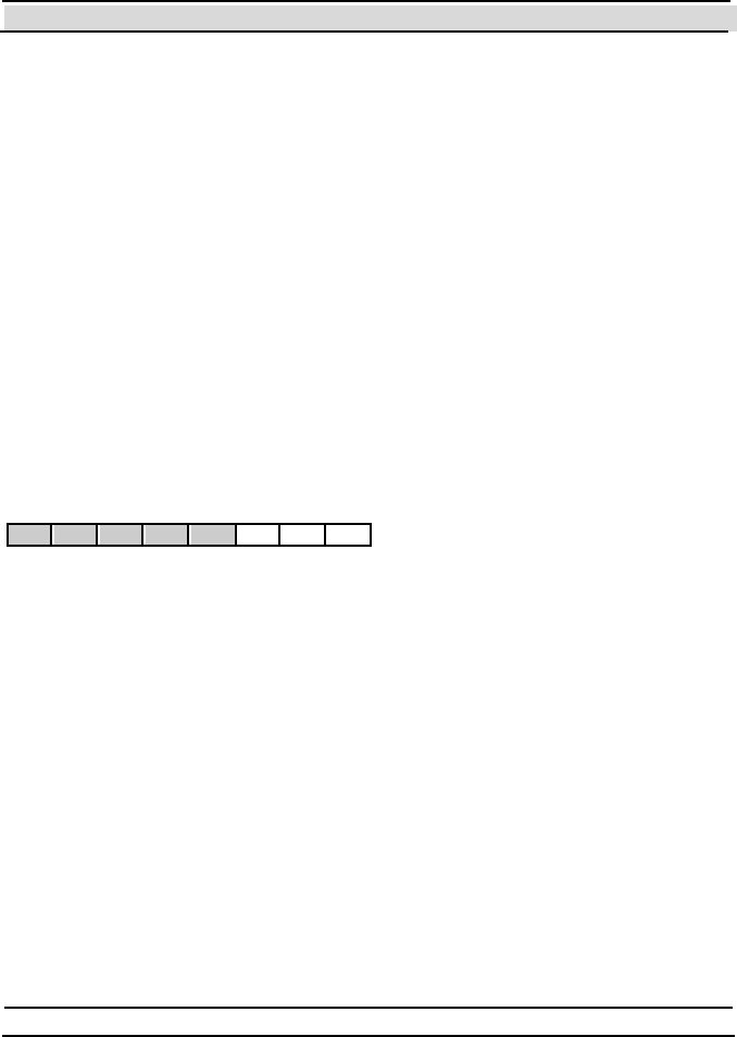
Chapter 8 System Parameters and Commands
- 146 - Hi-G-Tek Ltd. Micro elec tro nics & A sset Tra cking Techno logy
Flags
Seal O bject Property Fl a gs (Hidden property)
Access Read & Write.
Description Bit oriented value that controls specific
aspects of the DataSeal's behavior.
Constant in
HGTSeal ParameterC odeEnum
HGTFlags (14h )
Verify Mask in
HGTVerifyMaskEnum
(not supported).
Data Type Byte
Remarks
The format of this parameter is as follows:
7 6 5 4 3 2 1 0
Sp Sp Sp Sp Sp A E M
Where:
Sp - not used (spare) - must be 0.
A – if A = 1, after the DataSeal has sent a Burst message it waits for an
immediate acknowledge from a DataReader. See the description of the
ABM flag in the DataReader's Mode parameter in section 8.6 for more
information about this flag.
E – if E = 1 then the internal coding of the Date & T ime in the DataSeal
Event records is the new format, which has an accuracy of 1 second
(instead of 1 minute).
M – if M = 1 then the internal coding of the Date & T ime when returned as
a response to Ve rif y or Tampered, or in a Burst message (when the Mask
parameter contains the appropriate flag), is the new format, which has an
accuracy of 1 second (instead of 1 minute).

Chapter 8 System Parameters and Commands
Hi-G-Tek Ltd. Micro electro nics & Asset Tracking Technology - 147 -
Global
Seal O bject Property (not supported).
Access Read-Only.
Description Determines whether the DataSeal will
respond to Ve ri f y commands that are
sent from a DataReader with a different
OrgID.
Constant in
HGTSeal ParameterC odeEnum
HGTAcce ptGl o balComman ds (1 5h)
Verify Mask in
HGTVerifyMaskEnum
(not supported).
Data Type Byte
Remarks
If the value of this parameter is 1, the DataSeal will respond to Ve ri f y
commands even if the OrgID of the DataReader is not the same as of the
DataSeal. Nevertheless, only the following parameters can be retrieved by a
DataReader with a different OrgID: Short Status, Date & Time , Nu m be r
of Events, Fi rm wa re Ve rsi on and Se al Stam p.
See chapter 6 for more information about this parameter.
Include User Data in Verify Response
Seal Object Property UserData
Access Read-Only

Chapter 8 System Parameters and Commands
- 148 - Hi-G-Tek Ltd. Micro elec tro nics & A sset Tra cking Techno logy
Description Returns a byte array corresponding to a
portion of the DataSeal's memory that
was reque st ed in a Ve ri f y or
Tampered command or in a Burst
message
Constant in
HGTSeal ParameterC odeEnum
(not supported)
Verify Mask in
HGTVerifyMaskEnum
HGTUserDataVerifyMask (4)
Data Type Array of Bytes
Remarks
In fact, this in not a Parameter of the DataSeal, and cannot be read or
written using the Rea d P a rame te rs an d W ri te Pa ra mete rs co m man ds.
Instead, it is a flag in the Ve ri f y and Tampered co mm an ds t h at indicat es
that a block of the User Data is requested, and that the command includes
the address and size of this block after the Mask argument.
When the DataSeal responds to the Ve ri fy or Tampered command it
returns the data that corresponds to the specified address and size.
Even though this property is Read-Only, you can write to the User Data
area using the Write Data command.
Internal Firmware Version
Seal O bject Property In te rna l Fi rm wa re Ve rsion (Hidden
property).
Access Read-Only.
Description Internal version number (build number)
of the DataSeal's firmware.

Chapter 8 System Parameters and Commands
Hi-G-Tek Ltd. Micro electro nics & Asset Tracking Technology - 149 -
Constant in
HGTSeal ParameterC odeEnum
H G TIn te rn al Fi rm ware Ve rsi on (40h).
Verify Mask in
HGTVerifyMaskEnum
(not supported).
Data Type Byte.
Remarks
See also the Fi rm ware Ve rsi on parameter.
Last Date & Time Update
Se al O bject Prope rty LastDate TimeUpdate
Access Read-Only.
Description The date & time of the last time that the
Date & Time parameter was written.
Constant in
HGTSeal ParameterC odeEnum
HGTLastDateTimeUpdate (38h).
Verify Mask in
HGTVerifyMaskEnum
(not supported).
Data Type Date
Remarks
See also the Minimal Inte rval between Time Updates parameter.
Last Set Reader ID
Seal O bject Property LastSetReader
Access Read-Only

Chapter 8 System Parameters and Commands
- 150 - Hi-G-Tek Ltd. Micro elec tro nics & A sset Tra cking Techno logy
Description Indicates the Reader ID of the device
that sent the last Se t command (or any
of its variants) to the DataSeal.
Constant in
HGTSeal ParameterC odeEnum
HGTLastSetReader (9)
Verify Mask in
HGTVerifyMaskEnum
HGTLastSetReaderVe rifyMask (2 )
Data Type Long (Reader ID), or Re a de r object.
See the online help for more
information about the type of this
property.
Life Counter
Se al O bject Prope rty LifeCounte r
Access Read-Only
Description This value is initialized at the factory to
a value of 2048 and it is decrement ed in
each Se t command.
Constant in
HGTSeal ParameterC odeEnum
HGTLifeCounter (4 )
Verify Mask in
HGTVerifyMaskEnum
HGTLifeCounterVerifyMask (800h)
Data Type Long. Max value: 65535.
Long Status
Se al O bject Prope rty LongStatus

Chapter 8 System Parameters and Commands
Hi-G-Tek Ltd. Micro electro nics & Asset Tracking Technology - 151 -
Access Read-Only
Description Returns a bit field of the flags that
represent the status of the DataSeal.
Constant in
HGTSeal ParameterC odeEnum
HGTLongStatus (7)
Verify Mask in
HGTVerifyMaskEnum
HGTLongStatusVerifyMask (100h)
Data Type HGTSe alLongStatusBi tEnum (Long)
Remarks
This parameter contains all the status flags of the DataSeal (including these
t hat ar e p art of t h e Short Status parameter).
Use the constants in the HGTSe alLongS tatu sBi tEnum enumeration to
determine the state of the specific flags. Each flag has also a corresponding
boolean property in the Se al object.
Even though this parameter is read-only, some of the flags can be set using
the Set Status co mm an d ( Seal.SetStatus).
Section 8.2.1 contains descriptions of the various flags.
Low Battery Error Threshold
Seal O bject Property LowBatteryErrorThreshold (Hidden
property)
Access Read-Only.
Description The highest value of the battery voltage
that will cause the Low Battery Error
st at us flag to be set .
Constant in
HGTSeal ParameterC odeEnum
HGTLowBatte ryErrorThreshold
(61h).

Chapter 8 System Parameters and Commands
- 152 - Hi-G-Tek Ltd. Micro elec tro nics & A sset Tra cking Techno logy
Verify Mask in
HGTVerifyMaskEnum
(not supported).
Data Type Byte. Unit is of internal A/D converter.
Value 112
Remarks
This paramet er is factory configured and cannot be changed.
See also the Low Battery Warning Threshold, and the Batte ry Voltage
Value parameters.
Low Battery Warning Threshold
Seal O bject Property LowBatteryWarningThreshold
(Hidden property)
Access Read-Only.
Description The highest value of the battery voltage
that will cause the Low B a tte ry
Warning st at us flag to be set .
Constant in
HGTSeal ParameterC odeEnum
HGTLowBatte ryWarningThreshold
(61h).
Verify Mask in
HGTVerifyMaskEnum
(not supported).
Data Type Byte. Unit is of internal A/D converter.
Value 104
Remarks
This paramet er is factory configured and cannot be changed.
See also the Low Batte ry Error Threshold, and the Battery Voltage
Value parameters.

Chapter 8 System Parameters and Commands
Hi-G-Tek Ltd. Micro electro nics & Asset Tracking Technology - 153 -
Maxim al Alert and Close Burst Retries
Seal O bject Property MaxAlertBurstRetries
Access Read & Write.
Description Determines the number of times that
the DataSeal will transmit an Ale rt
Burst message or a Close Burst
message if it doesn't receive an
acknowledge.
Constant in
HGTSeal ParameterC odeEnum
H G TMa x Ale rt Bu rs tRe t ries (7 6h).
Verify Mask in
HGTVerifyMaskEnum
(not supported).
Data Type Byte
Default Value 10
Remarks
See also the Ale rt Bu rs t Pe ri o d parameter.
Maxim al Deep Sleep Burst Retries
Seal O bject Property MaxDeepSleepBurstRetries
Access Read & Write.
Description Determines the number of times that
the DataSeal will transmit a Dee p
Slee p Burst message if it doesn't
receive an acknowledge.
Constant in
HGTSeal ParameterC odeEnum
HGTMaxDeepSleepBurstRetries
(78h)

Chapter 8 System Parameters and Commands
- 154 - Hi-G-Tek Ltd. Micro elec tro nics & A sset Tra cking Techno logy
Verify Mask in
HGTVerifyMaskEnum
(not supported).
Data Type Byte
Default Value 5
Remarks
See also the Dee p Slee p Burst Pe riod Parameter.
Maximal Difference in Time Update
Seal Object Property MaxTimeDiffUpdate
Access Read-Only.
Description Updating the Date & Time Parameter
is allowed only if the difference from
the current value is less than the value
of this Parameter.
Constant in
HGTSeal ParameterC odeEnum
HGTMaxTimeDiffUpdate (37h).
Verify Mask in
HGTVerifyMaskEnum
(not supported).
Data Type Byte. Unit: minutes.
Value 8 minutes.
Remarks
This Paramet er is fact ory configured and cannot be changed.
See also the Minimal Inte rval between Time Updates Parameter.

Chapter 8 System Parameters and Commands
Hi-G-Tek Ltd. Micro electro nics & Asset Tracking Technology - 155 -
Maxim al Message Size
Seal O bject Property MaxMessageSize (Hidden property)
Access Read-Only.
Description The maximal size in bytes of an RF
message that the DataSeal can send.
Constant in
HGTSeal ParameterC odeEnum
HGTMaxMessageSize (52h).
Verify Mask in
HGTVerifyMaskEnum
(not supported).
Data Type Byte
Value 80
Remarks
This Paramet er is fact ory configured and cannot be changed.
Maxim al Number Of Events
Seal Object Property MaxNumberOfEvents
Access Read-Only.
Description The maximal number of Event records
that the DataSeal can store.
Constant in
HGTSeal ParameterC odeEnum
HGTMaxNumberOfEvents (50h).
Verify Mask in
HGTVerifyMaskEnum
(not supported).
Data Type Byte
Value 55

Chapter 8 System Parameters and Commands
- 156 - Hi-G-Tek Ltd. Micro elec tro nics & A sset Tra cking Techno logy
Remarks
This Paramet er is fact ory configured and cannot be changed.
See also the Number of Events, and the Number of Scroll Events
Parameters. See also the next section for further information about the
Events Memory and the DataSeal Events.
Minimal Interval between Time Updates
Seal O bject Property MinIntervalBetweenTimeUpdates
Access Read-Only.
Description Updating the Date & TimeParameter
is only allowed if a the interval
specified by t his Parameter has passed
since the last update.
Constant in
HGTSeal ParameterC odeEnum
HGTMin Inte rvalBetw ee nTimeU pdate s
(36h)
Verify Mask in
HGTVerifyMaskEnum
(not supported).
Data Type Byte. Un it : week s.
Value 13 weeks (3 months).
Remarks
This Paramet er is fact ory configured and cannot be changed.
See also the Maximal Difference in Time Update parameter.
Number of Events
Seal Object Property EventsCount
Access Read-Only

Chapter 8 System Parameters and Commands
Hi-G-Tek Ltd. Micro electro nics & Asset Tracking Technology - 157 -
Description Returns the number of Event records
t hat ar e current ly wr itt en in t h e Event s
Memory of the DataSeal.
Constant in
HGTSeal ParameterC odeEnum
HGTEve n tsC oun t (3)
Verify Mask in
HGTVerifyMaskEnum
HGTEventsCountVerifyMask
(1000h)
Data Type Byt e
Remarks
The value of this Parameter may vary according to the version of the
DataSeal's firmware, and according to the value of the Maximal Number
of Events parameter.
Number of Scroll Events
Seal O bject Property NumberOfScrollEvents
Access Read-Only.
Description The size of the Scrollable Portion of the
Events Memory, specified by the
number of Event records that can be
stored in it.
Constant in
HGTSeal ParameterC odeEnum
HGTNumberOfScrollEvents (51h).
Verify Mask in
HGTVerifyMaskEnum
(not supported).
Data Type Byte
Value 10

Chapter 8 System Parameters and Commands
- 158 - Hi-G-Tek Ltd. Micro elec tro nics & A sset Tra cking Techno logy
Remarks
This Paramet er is fact ory configured and cannot be changed.
See also the Maximal Numbe r of Eve nts, and the Number of Events
Parameters. See also the next section for further information about the
Events Memory and the DataSeal Events.
OrgID & Department
Seal Object Property OrgID
Access Read-Only
Description The identifier of the organization and
of the department within the
organization.
Constant in
HGTSeal ParameterC odeEnum
HGTOrgID (12h)
Verify Mask in
HGTVerifyMaskEnum
HGTOrgIDVerifyMask (40h)
Data Type Long
Remarks
The first (most significant) bytes of this parameter are the OrgID value, and
the 3rd byt e is t he Depart ment .
See chapter 6 for further details about the OrgID & De pa rtmen t
Parameters.
RS SI
Seal O bject Property RSSI
Access Read-Only

Chapter 8 System Parameters and Commands
Hi-G-Tek Ltd. Micro electro nics & Asset Tracking Technology - 159 -
Description Returns the reception level of the last
RF command.
Constant in
HGTSeal ParameterC odeEnum
HGTRSSI (8)
Verify Mask in
HGTVerifyMaskEnum
HGTRSSIVerifyMask (80h )
Data Type Byte
Seal ID
Seal O bject Property Se al ID (binary fo rm at ), Fo rma tB
(string format)
Access Read-Only*.
Description This is the identifier of the DataSeal.
Each DataSeal has a unique Seal ID
that is given to it in the factory.
Constant in
HGTSeal ParameterC odeEnum
HGTSealID1 (10h) – first 2 bytes.
HGTSe al ID2 (11h) – last 4 byt es.
Verify Mask in
HGTVerifyMaskEnum
(not supported).

Chapter 8 System Parameters and Commands
- 160 - Hi-G-Tek Ltd. Micro elec tro nics & A sset Tra cking Techno logy
Data Type SealID: SEAL_ID type (contains an
array of 6 bytes)
Fo rm atB : String in t he fo r mat
AAAAnnnnnnnn where A is any letter
from A to Z, and n is any digit from 0
to 9.
When read using HGTSealID1 an d
HGTSealID2: Both values are of type
Long: HGTS eal ID1 returns the first 2
byt es (0-65535) and HGTS eal ID2
ret urns the last 4 bytes (0-FFFFFFFFh)
Remarks
*Even though the Parameter in the DataSeal is Read-Only, the SealID and
Fo rm atB properties of the Seal object in DataSealLib are read/write. See
the online help for further details about these properties.
Seal Stamp
Se al O bject Prope rty Se alStamp
Access Read-Only
Description This is a unique (random) value that
DataSeal generates each time it is being
opened or closed, or when it receives
one of the Set commands.
Constant in
HGTSeal ParameterC odeEnum
HGTSe alStamp (1 7h)
Verify Mask in
HGTVerifyMaskEnum
HGTSe alStampVe ri fyMask (20h)
Data Type Long. Max value: 65535.

Chapter 8 System Parameters and Commands
Hi-G-Tek Ltd. Micro electro nics & Asset Tracking Technology - 161 -
Remarks
This value is also recorded in each Event record.
If you read only the Status of the DataSeal periodically, you may see the
same Status even though the DataSeal has been opened, closed or Set
between the 2 interrogations. By reading also the Seal Stamp, you can
determine if something like this happens.
Short Status
Se al O bject Prope rty Sh ortS tatu s
Access Read-Only
Description Returns a bit field of the most
important flags that represent the status
of the DataSeal.
Constant in
HGTSeal ParameterC odeEnum
HGTS ho rtS ta tus (0)
Verify Mask in
HGTVerifyMaskEnum
HGTS ho rtS ta tus Ve ri fy Mask (8000h)
Data Type HGTSe alShortS tatu sBi tEnum (byt e)

Chapter 8 System Parameters and Commands
- 162 - Hi-G-Tek Ltd. Micro elec tro nics & A sset Tra cking Techno logy
Remarks
This parameter is part of the Long Status Parameter which contains all the
status flags of the DataSeal.
Use the constants in the HGTSealShortStatusBitEnum en um erat io n t o
determine the state of the specific flags. Each flag has also a corresponding
boolean property in the Se al object.
Section 8.2.1- The DataSeal Status Flags contains descriptions of the
various flags.
Siz e of Us er Dat a
Seal O bject Property UserDataSize
Access Read-Only.
Description The size of the User Data memory area
in the DataSeal.
Constant in
HGTSeal ParameterC odeEnum
HGTUserDataSize (42h).
Verify Mask in
HGTVerifyMaskEnum
(not supported).
Data Type Byte.
Value About 2K
Remarks
The exact value of this Parameter depends on the version of the DataSeal's
firmware, and on the Maximal Nu m ber of Eve n ts Parameter.
Sleep Duration Unit
Se al O bject Prope rty SleepDurationUnit

Chapter 8 System Parameters and Commands
Hi-G-Tek Ltd. Micro electro nics & Asset Tracking Technology - 163 -
Access Read & Write.
Description This Parameter defines the units for the
Sleep Duration argument in the Ve ri fy
and Tampered commands.
Constant in
HGTSeal ParameterC odeEnum
HGTSleepDurationUnit (33h)
Verify Mask in
HGTVerifyMaskEnum
(not supported).
Data Type Byte. Unit is seconds.
Default Value 5
Remarks
See the description of the Ve ri f y command for more information about this
parameter.
Time Filter for Read (Footprint) Events
Seal O bject Property TimeFilterForReadEvent
Access Read & Write.
Description If the interval between 2 Re a d
(Footprint) Events is less than the value
of this Parameter then the 2nd Ev ent
record won't be written.
Constant in
HGTSeal ParameterC odeEnum
HGTTimeFilterForReadEvent (6Ah).
Verify Mask in
HGTVerifyMaskEnum
(not supported).
Data Type Byte. Unit is Tw .

Chapter 8 System Parameters and Commands
- 164 - Hi-G-Tek Ltd. Micro elec tro nics & A sset Tra cking Techno logy
Default Value 0
Remarks
If the value of this Parameter is 0, then Re a d (Footprint) Event record are
alway s wr it t en .
The purpose of this Parameter is to prevent too many Event records to be
written if a DataReader performs a Ve ri fy command wit h Footprint
cyclically.
See the DataReader's SYS Parameter, and the Re a d Event fo r furt her
details.
Tp (Wakeup Time Interval in Deep Sleep Mode)
Seal O bject Property Tp (hidden property)
Access Read & Write.
Description The interval in which the DataSeal
wakes up in Deep Sleep Mode, in order
to check for a HF Hard Wakeup RF
command.
Constant in
HGTSeal ParameterC odeEnum
HGTTp (32h)
Verify Mask in
HGTVerifyMaskEnum
(not supported).
Data Type Long. Max value: 65535. Unit is
1/1.024ms (0.976ms).
Default Value 10000 (9.766 seconds)
Remarks
In Deep Sleep mode, the DataSeal wakes up in the interval specified by this
Parameter, to check for a Hard Wakeu p command in HF.

Chapter 8 System Parameters and Commands
Hi-G-Tek Ltd. Micro electro nics & Asset Tracking Technology - 165 -
Ts (Time Slot Duration)
Seal O bject Property Ts (hidden property)
Access Read-Only.
Description Indicates the duration of each time slot
in Multi Addressed commands without
arguments.
Constant in
HGTSeal ParameterC odeEnum
HGTTs (30h)
Verify Mask in
HGTVerifyMaskEnum
(not supported).
Data Type Long. Max value: 65535. Unit is
1.024ms.
Value 41
Remarks
This Paramet er is fact ory configured and cannot be changed.
Tw (Wakeup Time Interval)
Seal O bject Property Tw (hidden property)
Access Read & Write.
Description The interval in which the DataSeal
wakes up in Normal Mode, in order t o
check for HF RF commands.
Constant in
HGTSeal ParameterC odeEnum
HGTTw (31h)
Verify Mask in
HGTVerifyMaskEnum
(not supported).

Chapter 8 System Parameters and Commands
- 166 - Hi-G-Tek Ltd. Micro elec tro nics & A sset Tra cking Techno logy
Data Type Long. Max value: 65535. Unit is
1/1.024ms (0.976ms).
Default Value 3000 (2.93 seconds)
Remarks
See section 8.1 - The High Frequency RF Protocol for more information
about this Parameter.
User Parameter 1 and User Parameter 2
Seal O bject Property UserParameter1
UserParameter2
Access Read & Write
Description Each of these Parameters are strings of
8 bytes that the user can use to store
anything he wants.
Constant in
HGTSeal ParameterC odeEnum
HGTUserParameter1 (68h)
HGTUserParameter2 (69h)
Verify Mask in
HGTVerifyMaskEnum
HGTUserParameter1VerifyMask
(10h)
HGTUserParameter2VerifyMask (8)
Data Type String. Max length: 8 bytes.
Remarks
These Parameters can be used by the user for any purpose.

Chapter 8 System Parameters and Commands
Hi-G-Tek Ltd. Micro electro nics & Asset Tracking Technology - 167 -
8.2.1 The DataSeal Status Flags
The Long Status Parameter of the DataReader is a 32-bit value which each
bit represents a specific flag of Status. T he Short Status Parameter is the 8
most significant bits of the Long Status.
Below are the descriptions of each of the Status flags: (All the flags are
included in t he Long Status, and the first 8 are also included in the Short
Status)
Tampered
Seal Object Property Tampered
Mne monic S/T
Description This flag gets set when the Sealing
Wire is opened or its electrical
resistance changes. It is cleared only by
one of the Set commands.
Constant in
HGTSealShortStatusBitEnum
HGTTamperedShort (80h)
Constant in
HGTSealLongStatusBitEnum
HGTStatusTampered (80000000h)
Low Battery Warning
Se al O bject Prope rty LowBatte ryW arning
Mne moni c LBW

Chapter 8 System Parameters and Commands
- 168 - Hi-G-Tek Ltd. Micro elec tro nics & A sset Tra cking Techno logy
Description This flag gets set when the DataSeal's
batt ery volt age get s below the value of
the Low Battery Warning Threshold
Parameter.
Constant in
HGTSealShortStatusBitEnum
HGTLowBatte ryWarningShort (40h )
Constant in
HGTSealLongStatusBitEnum
HGTStatusLowBatteryWarning
(40000000h)
Remarks
If this flag is on, the DataSeal is still functioning. However, you should
replace the DataSeal as soon as possible before it stops functioning.
Opened
Seal O bject Property O pened
Mne monic O /C
Description This flag is on when the Sealing Wire
is open, and off when it is closed.
Constant in
HGTSealShortStatusBitEnum
HGTOpenShort (20h )
Constant in
HGTSealLongStatusBitEnum
HGTStatusOpen (20000000h)
Remarks
When this flag is on, the Tampered flag is also set (if it wasn't yet).
Suspended Set
Seal O bject Property SuspendedSet

Chapter 8 System Parameters and Commands
Hi-G-Tek Ltd. Micro electro nics & Asset Tracking Technology - 169 -
Mne monic SS
Description This flag gets set when a Suspende d
Se t command is received, and stays on
until the Sealing Wire is closed.
Constant in
HGTSealShortStatusBitEnum
H G TS us pe n de dSe tSh ort (10h )
Constant in
HGTSealLongStatusBitEnum
HGTStatusSuspendedSet
(10000000h)
Sealing Wire Changed
Se al O bject Prope rty Se alWireCh an ge d
Mne monic W RC
Description This flag gets set when the electrical
resistance of the Sealing Wire changes
relative to what it was during the last
Se t operation.
Constant in
HGTSealShortStatusBitEnum
H G TS us pe n de dSe tSh ort (8h)
Constant in
HGTSealLongStatusBitEnum
HGTStatusSuspendedSet (8000000h)
Remarks
This may indicate that a thief tries to short the Sealing Wire.
Deep Sleep
Se al O bject Prope rty Dee pSleep
Mne monic SL

Chapter 8 System Parameters and Commands
- 170 - Hi-G-Tek Ltd. Micro elec tro nics & A sset Tra cking Techno logy
Description Indicates whether the DataSeal is in
Deep Sleep mode.
Constant in
HGTSealShortStatusBitEnum
HGTDee pSlee pShort (4h)
Constant in
HGTSealLongStatusBitEnum
HGTStatusDee pSleep (4000000h)
General Error
Seal O bject Property Ge neralError
Mne monic GE
Description Indicates an error that is indicated by
flags of the Long Status th at ar e not
part of the Short Status.
Constant in
HGTSealShortStatusBitEnum
HGTGeneralErrorShort (2)
Constant in
HGTSealLongStatusBitEnum
HGTStatusGeneralError (2000000h)
Remarks
This flag's value (0 or 1) is the logical OR of the following flags: Li fe
Counte r 0, Re al Time Cl ock Error, Low Battery Error, Database
Error, Database Corrupted, Hardware Error an d Illegal OrgID.
Approved Open
Se al O bject Prope rty ApprovedO pen
Mne monic AO

Chapter 8 System Parameters and Commands
Hi-G-Tek Ltd. Micro electro nics & Asset Tracking Technology - 171 -
Description If the Opened flag is on, this flag
indicates whether the open is approved.
If the Opened flag is off, this flag
indicates whether opening the DataSeal
is allowed.
Constant in
HGTSealShortStatusBitEnum
HGTApprove dO penShort (1)
Constant in
HGTSealLongStatusBitEnum
HGTStatusApprovedO pen
(1000000h)
Remarks
This flag get s set using t he Approve O pen command, and unset according
to the arguments of that command.
Opening the Sealing Wire while this flag is on does not prevent the
Tampered flag from turning on, rather it is possible to detect that this is an
allowed "tampered" situation by examining the Approved Open flag.
Life Counter 0
Se al O bject Prope rty LifeCounte rZe ro
Mne moni c LC 0
Description When the Life Cou nte r Parameter
reaches 0, this flag is set. In this case
the DataSeal ceases to write Event
records.
Constant in
HGTSealLongStatusBitEnum
HGTStatusLifeCounte rZe ro
(800000h)
Remarks
The Life C ounte r Parameter is decremented on each open and close
events, and when a Set command is issued.

Chapter 8 System Parameters and Commands
- 172 - Hi-G-Tek Ltd. Micro elec tro nics & A sset Tra cking Techno logy
Real Time Clock (RTC) Error
Seal O bject Property RTC Error
Mne monic RTC
Description Indicates an error in the Real Time
Clock of the DataSeal.
Constant in
HGTSealLongStatusBitEnum
HGTStatusRTCError (400000h)
Remarks
You can clear this flag using the Set/Reset Status command.
Low Battery Error
Seal O bject Property LowBatteryError
Mne moni c LBE
Description This flag gets set when the DataSeal's
batt ery volt age get s below the value of
the Low Battery Error Threshold
Parameter.
Constant in
HGTSealLongStatusBitEnum
HGTStatusRTCError (200000h)
Remarks
When this flag is on, the DataSeal is about to stop functioning, and you
should replace the DataSeal immediately.
Database Error (Corrupted and Restored)
Se al O bject Prope rty DBCorrupte dAndRe store d

Chapter 8 System Parameters and Commands
Hi-G-Tek Ltd. Micro electro nics & Asset Tracking Technology - 173 -
Mne monic DBE
Description This flag indicates that an error in the
DataSeal's internal database was
detected, but successfully restored.
Constant in
HGTSealLongStatusBitEnum
HGTStatusDBCorruptedAndRestored
(100000h)
Remarks
You can clear this flag using the Set/Reset Status command.
Database Corrupted
Se al O bject Prope rty DBC orrupted
Mne monic DBC
Description This flag indicates that an error in the
DataSeal's internal database was
det ect ed, and could not be fixed.
Constant in
HGTSealLongStatusBitEnum
HGTStatusDBCorrupted (80000h)
Remarks
When this flag is on, you should replace the DataSeal.
Ne w Batter y
Se al O bject Prope rty Ne wB atte ry
Mne monic NB
Description Indicates that a battery was replaced.

Chapter 8 System Parameters and Commands
- 174 - Hi-G-Tek Ltd. Micro elec tro nics & A sset Tra cking Techno logy
Constant in
HGTSealLongStatusBitEnum
H G TS t at us Ne wBa ttery (20000h)
Remarks
This flag is used only with DataSeals with replaceable batteries.
You can clear this flag using the Set/Reset Status command.
Hardware Error
Seal O bject Property HardwareError
Mne monic HRE
Description Indicates that an hardware error was
det ect ed.
Constant in
HGTSealLongStatusBitEnum
HGTStatusHardwareError (10000h)
Remarks
When this flag is on, you should replace the DataSeal.
Illegal OrgID
Se al O bject Prope rty Ille galO rgID
Mne monic O ID
Description Indicates that communication with the
DataSeal was attempted from a device
wit h a different OrgID or Department .
Constant in
HGTSealLongStatusBitEnum
HGTS tatusIlle galO rgID (8000h)

Chapter 8 System Parameters and Commands
Hi-G-Tek Ltd. Micro electro nics & Asset Tracking Technology - 175 -
Remarks
This flag may indicate that someone tried to "hack" the DataSeal using
unauthorized equipment.
You can clear this flag using the Set/Reset Status command.
Command Failed
Se al O bject Prope rty Co mman dFaile d
Mne monic C MF
Description Indicates that the DataSeal could not
execute a command it received.
Constant in
HGTSealLongStatusBitEnum
HGTS tatusCom man dFaile d (4000h)
Remarks
You can clear this flag using the Set/Reset Status command.
Unr e cogn ize d Comm and
Se al O bject Prope rty Un re cognize dCom man d
Mnemonic UNC
Description Indicates that the DataSeal received a
command that it does not recognize.
Constant in
HGTSealLongStatusBitEnum
HGTS tatusUnre cognize dComman d
(2000h)

Chapter 8 System Parameters and Commands
- 176 - Hi-G-Tek Ltd. Micro elec tro nics & A sset Tra cking Techno logy
Remarks
One reason for this flag to be set can be in case you're using a DataReader
an d a COM DL L with a v er sio n s th at ar e newer t h at t he v er sio n of t h e
DataSeal, and you're trying to execute a new command that the DataSeal
does not recognize.
You can clear this flag using the Set/Reset Status command.
Close Burst Mode
Seal O bject Property CloseBurstMode
Mne monic BMC
Description Determines whether the DataSeal will
send a Burst message when the Sealing
Wire becomes closed.
Constant in
HGTSealLongStatusBitEnum
HGTStatusCloseBurstMode (1000h)
Remarks
The Burst message that is sent in this case is the Close Burst message.
You can set or clear this flag using the Set/Reset Status command.
Note: This flag is in effect only if the Ale rt Bu rs t Mo de flag is also set.
(Alert) Burst Mode
Seal Object Property AlertBurstMode
Mne monic BMU
Description Determines whether the DataSeal will
send Burst messages.

Chapter 8 System Parameters and Commands
Hi-G-Tek Ltd. Micro electro nics & Asset Tracking Technology - 177 -
Constant in
HGTSealLongStatusBitEnum
HGTStatusAlertBurstMode (800h)
Remarks
If this flag is on, the DataSeal will send an Alert Burst message when the
Sealing Wire becomes opened. The Burst message that is sent in this case is
the Ale rt Bu rs t message or t he Extended Alert Burst message.
This flag also determines whether ot her t ypes of Burst message is allowed.
If this flag is off, the DataSeal won't send any kind of Burst message.
This flag can be set using the Start Alert Burst Mode and Start Alert
Burst Mode for All Seals, and cleared using the Stop Alert Burst Mode
and Stop Alert Burst Mode for All Seals commands.
Buffer Full
Seal Object Property BufferFull
Mne monic BF
Description This flag is set if a Re a d D a ta , Rea d
Eve nts or Re a d P a rame te rs command
requests too much data that exceeds the
size of the DataSeal's output buffer.
Constant in
HGTSealLongStatusBitEnum
HGTStatusAlertBurstMode (8 0h)
Remarks
The largest block you can read is Maximal Me ssage Size – 13 (=67 byt es).
You can clear this flag using the Set/Reset Status command.
Scroll
Seal O bject Property Scroll

Chapter 8 System Parameters and Commands
- 178 - Hi-G-Tek Ltd. Micro elec tro nics & A sset Tra cking Techno logy
Mne moni c S RL
Description Indicates whether the Events Memory
began t o overwrite older Event records
in the Scrollable Portion of the Events
Memory, because the Events Memory
is full.
Constant in
HGTSealLongStatusBitEnum
HGTStatusScroll (40h )
Remarks
See t h e n ext sect io n for more in fo rm at ion about t h e Ev ent s Mem or y an d
the DataSeal Events.
High Fr e que ncy (HF) Dis able d
Seal Object Property HFDisabled
Mne monic HFD
Description Determines whether the DataSeal will
listen to the HF channel.
Constant in
HGTSealLongStatusBitEnum
HGTStatusHFDisabled (20h)
Remarks
When this flag is on the DataSeal will not open the HF receiver to listen for
messages.
You can set or clear this flag using the Set/Reset Status command. The
Temporarily Disable HF command, and the Ve rify and Tampered
commands with Sleep Duration argument that is not 0, also turn on this
flag for a specified period.
Note: This mode does not affect the Low Frequency channel.

Chapter 8 System Parameters and Commands
Hi-G-Tek Ltd. Micro electro nics & Asset Tracking Technology - 179 -
Send OrgID in Burst
Seal Object Property OrgIDBurst
Mne monic O IB
Description Determines whether the OrgID of the
DataSeal will be sent when it transmits
a Burst message.
Constant in
HGTSealLongStatusBitEnum
HGTStatusOrgIDBurst (10h )
Remarks
You can set or clear this flag using the Set/Reset Status command.
Accelerated Verify Mode
Seal O bject Property (Not supported).
Mnemonic AVM
Description Indicates that the DataSeal is in an
Accelerated Verify mode.
Constant in
HGTSealLongStatusBitEnum
HGTStatusAccelerate dVerifyMode
(8)
Remarks
See the Accele rate Ve rify command for further information about this flag.
8.3 Events
See chapter 6 for a general description of the Events Memory.

Chapter 8 System Parameters and Commands
- 180 - Hi-G-Tek Ltd. Micro elec tro nics & A sset Tra cking Techno logy
8.3.1 General Structure of an Event Record
Th ere ar e 2 m ain ty pes of Ev ent r eco r ds: Sho rt Ev ent Reco rd an d Lon g
Event Record. In DataSealLib, both types are represented by the SealEvent
class, but the Short Event Record does not use all the members. The
following SealEve nt class members are used both in Short Events and in
Long Event records:
Number – The sequential number of the Event record.
Code – The code (type) of the Event record. T he
HGTEventCodeEnum enumeration contains the constants for these
codes.
DateTime – T he date & time (in UTC) when the event occurred.
Se alStamp – The value of the Seal Stamp parameter when the event
occurred.
CRC – The Cyclic Redundancy Check code that ensures the validity of
the first part of the record.
The following Seal Eve n t class members are used only in the Long Event
records:
CodeEx – The code of the extension of the Event record. This is
always the same as Code + 80h.
Reade r ID – T he ID of the device that caused the Event (for example,
in a Set operation). Note that this is not necessarily an ID of a
DataReader – it could also be the ID of a DataT erminal, DataPort or
any other kind of device that could cause the Event.
Note: If DataSealLib recognizes the Reader ID as a DataReader that it
knows it returns the Rea de r object instead of the Reader ID itself.
Se alStamp2 – 2 Additional bytes that contain data specific to the type
of Event. Most Event types does not use this field at all.

Chapter 8 System Parameters and Commands
Hi-G-Tek Ltd. Micro electro nics & Asset Tracking Technology - 181 -
CRC2 - T he Cyclic Redundancy Check code that ensures the validity
of the second part of the record.
Below are the descriptions of the different Event types:
Set
Constant in
HGTEventCodeEnum
HGTSetEvent (1)
Type of Event record Long
When Written On a successful completion of a Set
command.
Remarks
This is always the first Event record in the Events Memory.
Sealing Wire Changed
Constant in
HGTEventCodeEnum
HGTWireTamperedEvent (2)
Type of Event record Short
When Written If the electrical resistance of the
Sealing Wire has changed relat ive t o
wh at it was wh en t h e last Set co mman d
was executed.
Low Battery Warning
Constant in
HGTEventCodeEnum
HGTLowBatteryWarningEvent (3)
Type of Event record Short

Chapter 8 System Parameters and Commands
- 182 - Hi-G-Tek Ltd. Micro elec tro nics & A sset Tra cking Techno logy
When Written When the DataSeal's battery voltage
gets below the value of the Low
B a tte ry W a rning Th re shol d
Parameter.
Remarks
There's no "Low Battery Error" Event because when the Low Batte ry
Error flag is set the DataSeal ceases to write Events.
Sealing Wire Opened
Constant in
HGTEventCodeEnum
HGTWireOpenedEvent (4)
Type of Event record Short
When Written When t he Sealing Wire is opened or
cut.
Sealing Wire Closed
Constant in
HGTEventCodeEnum
HGTWireClosedEvent (5 )
Type of Event record Short
When Written When the Sealing Wire is closed.
Soft Set
Constant in
HGTEventCodeEnum
HGTSoftSetEvent (7)
Type of Event record Long

Chapter 8 System Parameters and Commands
Hi-G-Tek Ltd. Micro electro nics & Asset Tracking Technology - 183 -
When Written On successful completion of a Soft Set
command.
Remarks
The Soft Set command is similar to the Set command, but does not clear
the Events Memory. Instead, it writes the Soft Set Event record.
Real Time Clock (RTC) Stopped
Constant in
HGTEventCodeEnum
HGTRTCStoppedEvent (8)
Type of Event record Short
When Written When the Built-in Test detects an error
in the Real Time Clock.
Database Corrupted and Restored
Constant in
HGTEventCodeEnum
HGTDBCorrupte dEve nt (9)
Type of Event record Short
When Written When the Built-in Test detects an error
in the DataSeal's internal Database, but
succeeds to restore it.
Remarks
If the DataSeal is not able to restore the database, it doesn't write Event
records, and you should replace the DataSeal.

Chapter 8 System Parameters and Commands
- 184 - Hi-G-Tek Ltd. Micro elec tro nics & A sset Tra cking Techno logy
Read (Footprint)
Constant in
HGTEventCodeEnum
HGTReadEvent (10)
Type of Event record Long
When Written On successful completion of one of the
Verify or Ta m pe re d commands, if bit
7 of the DataReader's SYS Parameter
of the DataReader is 1. Also written on
complet ion of t he Low-Frequency
Read command.
Date & Time Updated
Constant in
HGTEventCodeEnum
H G TTi m e U p date Eve n t (0Bh)
Type of Event record Long
When Written On successful completion of a Write
Parameters command that updat es the
Date & Time Parameter.
Value of Se alS tam p2 The high (MSB) byte cont ains the
number of minutes (signed) that was
added t o t he previous value of the Da te
& Ti me Parameter. The low (LSB)
byte is not used (0).
Suspended Set
Constant in
HGTEventCodeEnum
H G TS us pe n de dSe t Eve nt (0Ch)

Chapter 8 System Parameters and Commands
Hi-G-Tek Ltd. Micro electro nics & Asset Tracking Technology - 185 -
Type of Event record Long
When Written On successful completion of a
Suspende d Set co mm an d.
Remarks
If the Sealing Wire was opened when the Suspe nded Set co mm an d was
executed, the Suspended Set Event will first be appended to the existing
Events, and after closing the Sealing Wire, all the previous Event records
will be deleted, and the Suspende d Set Event will become the first.
Start Burst Mode
Constant in
HGTEventCodeEnum
HGTStartBurstModeEvent (0Dh)
Type of Event record Long
When Written On successful completion of a Start
Alert Burst Mode or Start Alert
Burst Mode for All Seals co mm an d.
Stop Burst Mode
Constant in
HGTEventCodeEnum
HGTStopBurstModeEvent (0Eh)
Type of Event record Long
When Written On successful completion of a Stop
Alert Burst Mode or Stop Alert Burst
Mode for All Seals co mm an d.

Chapter 8 System Parameters and Commands
- 186 - Hi-G-Tek Ltd. Micro elec tro nics & A sset Tra cking Techno logy
Start Deep Sleep Mode
Constant in
HGTEventCodeEnum
H G TS t a rt De e pSle e pMo de Eve n t
(0Fh)
Type of Event record Long
When Written On successful completion of a Dee p
Slee p comman d.
Remarks
After this Event the DataSeal enters Deep Sleep mode and stops writing
new Event records. After a Hard Wakeup command the DataSeal wakes
up, but it cont inues to writ e Event records only aft er a new Se t co mm an d is
executed.
Approved Open
Constant in
HGTEventCodeEnum
HGTApprovedOpenEvent (0Fh)
Type of Event record Long
When Written On successful completion of an
Approve Open command.
8.4 High-Frequency RF Commands Summ ary
There are 3 groups of HF RF commands: Addressed, M ult i Addresse d
(with or without arguments) and Broadcast (see section 8.1.2 - Addressing
Types for descriptions about these 3 groups). DataSealLib exposes each RF
command as a method of a class: Addressed commands are provided as
methods of the Seal class; Multi Addressed commands are provided as
methods of the Se als class, and Broadcast commands are provided as
methods of the Rea de r class.

Chapter 8 System Parameters and Commands
Hi-G-Tek Ltd. Micro electro nics & Asset Tracking Technology - 187 -
All of the methods in DataSealLib that execute RF commands take the
following 2 optional arguments (usually these are the last arguments):
RFCommandO bject – This argument is used for controlling specific
issues regarding the way that DataSealLib returns the results of the RF
command. When the command completes, its Re sul t property contains
the results. For further information about this argument and the
RFCommandO bject class see the online documentation.
ADI – This is the ADI (group ID) that will be sent with the command.
See chapter 6 for further information about ADI.
The following sections contain a summary of the (HF) RF commands and
their arguments. The R FC om m an dO bje c t an d ADI arguments are omitted
from each command, because they are common to all and described above.
Argument s that are relevant only t o Dat aSealLib and does not affect the RF
communicat ions, are omitt ed t oo. See t he online documentat ion for help
about these arguments. Note that there are default values to almost all
arguments of all the commands. See the online documentation for further
information about these default values.
8.4.1 Broadcast Commands
NOP (No Operation)
Me th od Reade r.NOP (Hidden method)
Description When a DataSeal receives this commands it does
nothing for the specified period. This is sometimes
useful when performing a Command Chain.

Chapter 8 System Parameters and Commands
- 188 - Hi-G-Tek Ltd. Micro elec tro nics & A sset Tra cking Techno logy
Arguments:
Name Type Description
Period Long Th e p eriod un til th e D ataS eal will
wait fo r the n ext comm and.
Resul t Ty pe Boole an
Result Description Always ret urns True (Dat aSeals don't respond t o
this command).
Remarks
See section 8.7 for further information about Command Chains.
Verify, Tampered
Method Reader.Verify
Description Detects which DataSeals are in the DataReader's
Receiving Zone, or which tampered DataSeals
are in the DataReader's Receiving Zone. It can
also read selected Parameters and/or User Data
from the receiving DataSeals.

Chapter 8 System Parameters and Commands
Hi-G-Tek Ltd. Micro electro nics & Asset Tracking Technology - 189 -
Arguments:
Name Type Description
M a sk HG TVerify Ma skEnum
enum eration
The set of param eters to request.
U s e th e ' O r' op er ato r t o com bi n e
m ore than on e co ns t ant from th e
HGT V erify M as kEnum
en um erat ion.
TamperedOnly Boolean Whether to ask only the tampered
DataSeal to respond. Internally,
Dat aS eal Lib us es thi s argum ent to
determines the type of the
command that will be sent (the
Verify comm and o r th e
Tampered command).
RFParameters RFParameters class Contains properties that controls
low-level features of the
comm and. See the Remarks below
fo r fu rt h er in fo r m at io n.
StartAddress Integer The starting address of the User
Dat a to requ est. Thi s argum ent is
rel evan t only i f th e
HGTUserDataVerifyMask flag is
in cl uded in th e Mask argum ent.
Length Byte The length in bytes of the User
Dat a to requ est. Thi s argum ent is
rel evan t only i f th e
HGTUserDataVerifyMask flag is
in cl uded in th e Mask argum ent.
Result Type Se als class
Result Description The Seals class contains the Se al o bject s t h at
represents the responded DataSeals. The
requested parameters are reflected through the
Se al objects' propert ies.
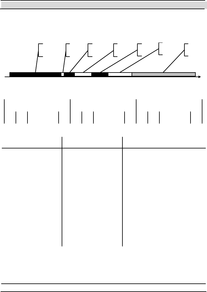
Chapter 8 System Parameters and Commands
- 190 - Hi-G-Tek Ltd. Micro elec tro nics & A sset Tra cking Techno logy
Remarks
The following scheme demonstrates the various parts of the Ve ri f y
command t hrough t ime:
t
Reader
Interroga tion
Header - IH
Operating
Interval 1 - I1
Operating
Interval 2 - I
2
Reader Master
Message -RMM
Receiving
Window
C a li b r at io n
Messages
Window
In t er l ac e
Window
The following scheme demonstrates the various parts of the Receiving
Window through time:
AW 1AW 2. . . . . . . AW Na RW 1RW 2. . . . . . . RWNr TW 1TW 2. . . . . . . TW Nt
Tam per WindowsRandom Windows
Assigned Windows
The RFPa rame te rs class has the following properties:
Name Type Description
Tcm Byte D urat ion of t h e C alib rat ion
Message Window. Units are
1.024m s. If 0 – th ere's no
Calibration Message Window.
The Calibration Message Window
is us ed al ong wi th the
HGTDistanceIndexVerifyMask
fl ag o f t h e Mask argument, to
determine the relative distance of
the DataSeal from the DataReader.
(Default is 0).
Tiw Integer Th e du ration o f th e R ead er
Interlace Window. Units are
1.024m s. (Defau lt is 0 ).

Chapter 8 System Parameters and Commands
Hi-G-Tek Ltd. Micro electro nics & Asset Tracking Technology - 191 -
Ts Byte Duration of the Time Slice
(window) that the DataReader
receives a single DataS eal
res pons e. T his duration m us t b e in
correlation with the number of
bytes that were requested in the
Mask an d Length arguments, and
with the value of the
RFParameters.Confirmation
Flag property. This property is
us uall y calcu lat ed au tom ati cally,
or y ou can use the SetBestT s
method to calculate it. Units are
1.024 ms
Na Byte N um ber of As sign ed Wi ndow s.
Thi s argum ent is cu rrent ly not
supported by the DataSeals.
Nr Byte N um ber of R andom Wi ndow s.
You can calculate the best value
fo r t his p roperty u sing the
DefaultsFor meth od.
Nt Byte Number of T amper Windows.
These windows are meant only for
D at aS eal s th a t t h ei r T am p er ed fl ag
is on.
Rr Byte T he 7 righ tmo st bit s are th e
number of random retries in the
Random Windows, which is the
num ber o f Wi nd ows in wh ich
each DataSeal chooses randomly
to send his responses.
The leftmost bit determines
whether the DataReader will send
a confirmation to a DataSeal when
it receives its response. This bit is
al so ex pos ed th rough th e
ConfirmationFlag p rop erty.
You can calculate the best value

Chapter 8 System Parameters and Commands
- 192 - Hi-G-Tek Ltd. Micro elec tro nics & A sset Tra cking Techno logy
fo r t his p roperty u sing the
DefaultsFor meth od.
Rt Byte Number of random retries in the
Tam per W ind ow s.
SleepDuration Byte If this parameter is not 0, and the
ConfirmationFlag is True, the
DataSeal will execute a
Temporarily Disable HF
comm and w ith t he du rati on
specified by this argument, upon
receiving the confirm ation. The
units of this arguments is
determined by the DataSeal's
Sleep Duration Unit parameter.
This is useful to avoid collisions
an d to sav e batt ery w hen you n eed
to receive large amount of
Dat aS eal s that are in th e sam e
zone.
Start Alert Burst Mode for All Seals, Stop Alert Burst Mode for
All Seals
Method Reader.SetAsyncAlertBurstMode
Description Causes all the DataSeals that receive this command
to start or to stop being in Alert Burst Mode by
setting or clearing their Ale rt Bu rst Mode st at us
flag.

Chapter 8 System Parameters and Commands
Hi-G-Tek Ltd. Micro electro nics & Asset Tracking Technology - 193 -
Arguments:
Name Type Description
BurstMode Boolean Determines whether to start or to
st op B urs t M ode. In ternally ,
Dat aS eal Lib us es thi s argum ent to
determines the type of the
command that will be sent (the
S tart Alert Bu rst Mod e for All
S eal s com m an d o r t h e S t op A l e rt
B urs t Mod e for A ll Seals
comm and).
Resul t Ty pe Boole an
Result Description Always ret urns True (Dat aSeals don't respond t o
this command).
Accelerate Verify
Method Reader.AccelerateVerify
Description Allows large amount of Dat aSeals to respond to a
Verify command in a short period of time, and in
high velocity (on a train, for example).
It does so by changing Tw temporarily to a smaller
value (shorter period).
Arguments:
Name Type Description
NewTw Integer The new (temporary) value of
Tw.

Chapter 8 System Parameters and Commands
- 194 - Hi-G-Tek Ltd. Micro elec tro nics & A sset Tra cking Techno logy
Phase Long The interval in seconds of the
time between the DataSeal
receives the comm and and until
it st arts th e Acti ve P eriod (t he
period in which Tw is repl aced
wi th NewTw).
ActiveInterval Long Th e du ration o f th e Act ive
In t erv al in seco nd s. T h e
resolution is the maximum of
th e fo llo wing tw o v alues : th e
original value of the Tw
param eter and th e valu e o f the
NewTw argument.
CheckReader Boolean See Remarks.
UseInVerify Boolean See Remarks.
UseInTamper Boolean See Remarks.
RestoreTwOnConfirmation Boolean Determines whether the
DataSeal should exit the Active
Period (restore Tw ) wh en i t
receives a confirmation to a
Verify response.
Resul t Ty pe Boole an
Result Description Always ret urns True (Dat aSeals don't respond t o
this command).

Chapter 8 System Parameters and Commands
Hi-G-Tek Ltd. Micro electro nics & Asset Tracking Technology - 195 -
Remarks
If the DataSeal received a Ve rif y command during the Act ive P eriod and
UseInVerify is True, upon receiving a confirmation flag to its response it
does the following:
If Res tore TwOnC onfirmation is T rue, it restores the original Tw , and
leaves the Active Period. If it is False, the DataSeal ignores further Ve ri f y
commands until the end of the Active Period. If CheckReader is True, the
DataSeal ignores only Ve ri fy commands t ransmitt ed by the same
DataReader.
The same thing applies for a Tampered command and the Use In Ta m pe r
flag.
When the DataSeal receives this command it sets the Accele ra te d Veri f y
Mode flag in the Long Status, and clears it when it leaves the Active
Period.
8.4.2 Addressed Commands
Addressed Verify
Me th od Se al.Ve ri fy
Description Verifies that a specific DataSeal is in the
DataReader's Receiving Zone. It can also read
selected parameters and/or User Data from that
DataSeal.
Arguments:
Name Type Description
M a sk HG TVerify Ma skEnum
enum eration
The set of param eters to request.
U s e th e ' O r' op er ato r t o com bi n e
m ore than on e co ns t ant from th e
HGT V erify M as kEnum
en um erat ion.

Chapter 8 System Parameters and Commands
- 196 - Hi-G-Tek Ltd. Micro elec tro nics & A sset Tra cking Techno logy
RFParameters RFParameters class Contains properties that controls
low-level features of the
comm and. See the Remarks of the
Verify com m a nd fo r fu rt h er
information. The following
properties are not applicable to
the Addressed Verify: Na, Nt
and Rt.
StartAddress Integer The starting address of the User
Dat a to requ est. Thi s argum ent is
rel evan t only i f th e
HGTUserDataVerifyMask flag is
in cl uded in th e Mask argum ent.
Length Byte The length in bytes of the User
Dat a to requ est. Thi s argum ent is
rel evan t only i f th e
HGTUserDataVerifyMask flag is
in cl uded in th e Mask argum ent.
Result Type Se al class
Result Description The original Seal objects that represents the
specified DataSeal. The requested parameters are
reflect ed t hrough the object propert ies.
Approve Open
Me thod Se al.ApproveO pen
Description Turns on the Approve d O pen flag in the
DataSeal's Status to indicate that it allows to be
opened.
Arguments:
Name Type Description

Chapter 8 System Parameters and Commands
Hi-G-Tek Ltd. Micro electro nics & Asset Tracking Technology - 197 -
ClearOnClose Boolean Wh et her th e D ataS eal sh ould
clear the Approved O pen fl a g
wh en th e S ealin g Wi re is clos ed
again.
Result Type Byte
Result Description The Short Status of the DataSeal.
Remarks
When the DataSeal receives this command it writes an Approved Open
Event record.
Temporarily Disable High Frequency
Me thod Se al.TempDisableHF
Description Turns on the HF Disabled flag in the DataSeal's
Status for a specified period.
Arguments:
Name Type Description
Period Long
(Max value: 65535).
Th e du ration in secon ds in w hich
the HF will be disabled.
InterruptOnTamper Boolean W het her the Dat aS eal wo uld
reactivate its HF receiver when a
Tampered Event o ccu rrs.
Result Type Byte
Result Description The Short Status of the DataSeal.
Re ad Eve n t s
Me thod Se al.ReadEvents

Chapter 8 System Parameters and Commands
- 198 - Hi-G-Tek Ltd. Micro elec tro nics & A sset Tra cking Techno logy
Description Returns all or part of the Event records that are
currently in the DataSeal's Events Memory.
Arguments:
Name Type Description
StartEventNumber Byte T he fi rs t Event num b er to read.
NumberOfEvents Byte Th e m axim um numb er of Ev ent
records to read.
Result Type Eve nts class
Result Description The returned Eve n ts object is a collection of
Se al Even t objects that represent the Event
records.
Re ad Dat a
Me thod Se al.ReadData
Description Reads a block of data from the User Data memory
of the specified DataSeal.
Arguments:
Name Type Description
BaseAddress Integer Th e fi rst add res s in the D ataS eal 's
User Data memory from which to
st art read in g.
BlockLength Integer The length in bytes of the block of
m emory to read from th e
DataSeal.
Result Type Array of Byte s.
Result Description The block of data that was read from the DataSeal.

Chapter 8 System Parameters and Commands
Hi-G-Tek Ltd. Micro electro nics & Asset Tracking Technology - 199 -
Remarks
The maximal possible Bl ock Len gth is 67 byt es.
Re ad Par amete rs
Me th od Seal.ReadParameters (for reading multiple
parameters)
Seal.ReadParameter (for reading single
parameter)
Description Reads the value of one or more Parameters of
the specified DataSeal.
Seal.ReadParameters Arguments:
Name Type Description
CodesAndValues SealCodesAndValues c l as s T h e c ol l e ct io n o f t h e
p ar am et ers t o r ead . S ee th e
on li ne do cum entati on fo r
fu rt h e r i n fo rm ati on r e g a rd in g
how to fill this collection.
Seal.ReadParameter Arguments:
Name Type Description
Code HGTSealParameterCodeEnum
enum eration
The code of the parameter
th at you wan t to read.
Result Type for
Seal.ReadParameters
SealCodesAndValues class
Resul t Des cri ptio n for
Seal.ReadParameters
The collection is filled with the values of the
parameters.
Result Type for
Seal.ReadParameter
Variant (according to the type of the parameter)

Chapter 8 System Parameters and Commands
- 200 - Hi-G-Tek Ltd. Micro elec tro nics & A sset Tra cking Techno logy
Result Description for
Seal.ReadParameter
The value of the parameter that was read.
Read Multi Access Data
Me thod Se al.ReadMul tiAccessData
Description Reads one or more blocks of data (possibly
inadjacent) from the User Data memory of the
specified DataSeal.
Arguments:
Name Type Description
AddressesAndSize s Variant An array that contains pairs of
Address and Size of the blocks of
User Data to read.
Result Type Array of bytes or an array of array of bytes – see
the online documentation for further information.
Result Description The result is t he request ed dat a.
Write Data
Me th od Se al.W ri te Data
Description Writes a block of data to the User Data memory of
the specified DataSeal.
Arguments:
Name Type Description
BaseAddress Integer Th e fi rst add res s in the D ataS eal 's
User Data memory to where you
want to write the data.
Data Array o f b ytes Th e d ata that yo u want t o writ e to
th D t S l

Chapter 8 System Parameters and Commands
Hi-G-Tek Ltd. Micro electro nics & Asset Tracking Technology - 201 -
the DataSeal.
Result Type Byt e
Result Description The Short Status of the DataSeal.
Write Parame ters
Me th od Se al.W ri te Pa ra mete rs (for writing multiple
parameters)
Se al.W ri te Pa ra mete r (for writing single
parameter)
Description Writes new value(s) to one or more Parameters of
the DataSeal.
Argu ments for Se al.W ri te Para mete rs :
Name Type Description
CodesAndValues SealCodesAndValues class A collection that contains
pairs of Parameter codes and
th e v alu es th at you want to
write to them.
Argu ments for Se al.W ri te Para mete r:
Name Type Description
Code HGTSealParameterCodeEnum
enum eration
The code of the parameter
that you want to update.
Value Variant (according to the
specific parameter)
The new value that you want
to write to that parameter.
Result Type Byte
Result Description The Short Status of the DataSeal.

Chapter 8 System Parameters and Commands
- 202 - Hi-G-Tek Ltd. Micro elec tro nics & A sset Tra cking Techno logy
Start Forced Burst
Method Seal.StartForcedBurst
Description Instructs the DataSeal to transmit a special Burst
message according to the specified arguments.
Arguments:
Name Type Description
M a sk HG TVerify Ma skEnum
enum eration
The set of parameters that you
want the DataSeal to transmit in
the Forced Burst m e ss a g es. U s e
t h e 'O r' op er ato r to com bi n e mo re
than one constant from the
HGTVerifyMaskEnum
en um erat ion.
Phase Long The interval in milliseconds since
the DataSeal received the
command and until it should start
send in g the Forced Burst
messages.
Period Long The mean interval, in miliseconds,
between retries (retransmits) of
the Forced Burst messages.
RandomDiff Long Th e rang e, in mi lis eco nd s, of th e
random variance from the mean
interval between retries of the
Forced Burst messages.
Retries Byte Th e m axim um n umb er of ret ries
that the DataSeal will send.
S peci fy 0 fo r un lim ited n umber o f
retries. Specify 255 to stop the
DataSeal from sending further
Forced Burst messages.
UserCode Byte A general purpose value that will
be s ent in t he Fo rced B urs t

Chapter 8 System Parameters and Commands
Hi-G-Tek Ltd. Micro electro nics & Asset Tracking Technology - 203 -
m ess ages, th at you m ay us e to
indicate the reason for the Forced
Bur st message.
StartAddress Integer T h e st art ad d res s o f t h e Us e r D at a
that will be transmitted in the
Forced Burst messages. The
HGTUserDataVerifyMask value
must be included in the Mask
argument in order to send data.
Length Byte The length in bytes of the User
Data that will be transmitted in
the Forced Burst m e ss a g es. T h e
HGTUserDataVerifyMask value
must be included in the Mask
argument in order to send data.
Result Type Byt e
Result Description The Short Status of the DataSeal.
Remarks
The DataSeal must be in Burst Mode in order to send the Fo rce d Bu rs t
messages.
Set/Reset Status
Method Seal.SetStatus
Description Sets or clears specified flags in the DataSeal's
Long Status.
Arguments:
Name Type Description
Mask HGTSealLongStatusBitEnum
enum eration
The mask of the flags that you
want t o set.
Value HGTSealLongStatusBitEnum
enum eration
The values of the flags that you
want t o set.

Chapter 8 System Parameters and Commands
- 204 - Hi-G-Tek Ltd. Micro elec tro nics & A sset Tra cking Techno logy
Result Type Byt e
Result Description The Short Status of the DataSeal.
Remarks
Not all flags in the Long Status can be changed. See section 8.2.1- T he
DataSeal Status Flags for information about which flags can be changed
using t his command.
8.4.3 Multi Addressed Commands
8.4.3.1 Multi Addressed Commands With Parameters
Multi Addressed Verify
Me th od Se als.Veri fy
Description Verifies that the specific DataSeals are in the
DataReader's Receiving Zone. It can also read
selected parameters and/or User Data from those
DataSeals.
Arguments:
Name Type Description
M a sk HG TVerify Ma skEnum
enum eration
The set of param eters to request.
U s e th e ' O r' op er ato r t o com bi n e
m ore than on e co ns t ant from th e
HGT V erify M as kEnum
en um erat ion.
RFParameters RFParameters class Contains properties that controls
low-level features of the
comm and. See the Remarks of the
Verify com m a nd fo r fu rt h er
information. The following
properties are not applicable to

Chapter 8 System Parameters and Commands
Hi-G-Tek Ltd. Micro electro nics & Asset Tracking Technology - 205 -
the Mult i Addressed Verify: Na,
Nt an d Rt.
StartAddress Integer The starting address of the User
Dat a to requ est. Thi s argum ent is
rel evan t only i f th e
HGTUserDataVerifyMask flag is
in cl uded in th e Mask argum ent.
Length Byte The length in bytes of the User
Dat a to requ est. Thi s argum ent is
rel evan t only i f th e
HGTUserDataVerifyMask flag is
in cl uded in th e Mask argum ent.
Result Type Se als class
Result Description The returned Se als object contains only the Se al
objects of the DataSeals that responded.
The requested parameters are reflected through the
Se al objects' propert ies.
Remarks
The maximal number of Dat aSeals that can be addressed using t his
command is 7. To address more than 7 DataSeals you can send this
command multiple times, or use a Command Chain.
8.4.3.2 Multi Addressed Commands Without Parameters
All the Multi Addressed commands without parameters can apply up to 8
DataSeals. T he result type is always a Seals object that contains only the
DataSeals that have responded. For all the commands their Sh ortS ta tu s
property is updat ed according to their response, and for t he Set, Suspended
Se t and Soft Set commands also the LongStatus and SealStamp properties
are updated.

Chapter 8 System Parameters and Commands
- 206 - Hi-G-Tek Ltd. Micro elec tro nics & A sset Tra cking Techno logy
Note: All t he 3 types of set are performed through DataSealLib using t he
Se als .SealSe t method. You specify the type of Set through t he SetO ptions
argument. See the online documentation for further information.
Set
Me thod Se als.SealSe t
Description Prepares the DataSeal for a new use.
Remarks
When a DataSeal receives this command it performs the following actions:
1. Clearing the following Status flags: Ta m p e re d, Lo w B atte ry
Warning, Opened, Suspended Set an d Sealin g Wi re Change d.
2. Deleting all the Event records from the Events Memory.
3. Write a new Set Event record.
4. The Last Set Reade r paramet er is updat ed.
The Set command fails in the following situations:
The DataSeal is in Deep Sleep mode.
Li fe Coun te r is 0.
The DataSeal's internal database is corrupted.
The Low Battery Error flag is on.
The Sealing Wire is open.
Suspended Set
Me thod Se als.SealSe t
Description Prepares the DataSeal for a new use.
Remarks

Chapter 8 System Parameters and Commands
Hi-G-Tek Ltd. Micro electro nics & Asset Tracking Technology - 207 -
When a DataSeal receives this command it performs the following actions:
If upon receiving the command the Sealing Wire is opened:
1. T urning on the Suspended Set flag in the Status is on
2. A Suspende d Se t Event is written.
3. After the Sealing Wire gets closed: the following Status flags are
cleared: Tampered, Low Battery Warning, Opened, Suspende d Se t,
Se aling Wi re Chan ge d, Approve d O pen and Database Error.
4. All the Event records are deleted from the Events Memory, except the
Su spende d Set Event, that becomes the first Event record.
5. The Last Set Reade r ID paramet er is updat ed.
If upon receiving the command the Sealing Wire is closed:
1. The following Status flags are cleared: Ta m pe re d, Lo w Batte ry
Warning, Opened, Suspended Set, Se aling Wi re Chan ge d,
Approve d Open and Database Error.
2. All the Event records are deleted from the Events Memory.
3. A new Suspended Set Event is written.
4. The Last Set Reade r ID paramet er is updat ed.
The Suspended Set command fails in the following situations:
The DataSeal is in Deep Sleep mode.
Li fe Coun te r is 0.
The DataSeal's internal database is corrupted.
The Low Battery Error flag is on.
Soft Set
Me thod Se als.SealSe t
Description Prepares the DataSeal for a new use without
deleting existing Event records.

Chapter 8 System Parameters and Commands
- 208 - Hi-G-Tek Ltd. Micro elec tro nics & A sset Tra cking Techno logy
Remarks
When a DataSeal receives this command it performs the following actions:
1. Clearing the following Status flags: Ta m p e re d, Lo w B atte ry
Warning, Opened, Suspended Set an d Sealin g Wi re Change d.
2. Write a new Soft Se t Event record.
3. The Last Set Reade r ID paramet er is updat ed.
The Soft Set command fails in the following situations:
The DataSeal is in Deep Sleep mode.
Li fe Coun te r is 0.
The DataSeal's internal database is corrupted.
The Low Battery Error flag is on.
The Sealing Wire is open.
Re se t Dat a
Me th od Se als .ResetDataBl ock
Description Initializes all the User Data memory to 0's.
Deep Sleep
Me thod Se als.DeepSleep
Description Puts the specified DataSeals in Deep Sleep mode.
Remarks
When a DataSeal receives this command it performs the following actions:
1. The Deep Sleep flag in the DataSeal's Status is turned on.
2. A Dee p Sleep Event is written.
3. If the Alert Burst Mode flag is on, an Ale rt Bu rs t message sending

Chapter 8 System Parameters and Commands
Hi-G-Tek Ltd. Micro electro nics & Asset Tracking Technology - 209 -
process begins.
If the HF flag in the Application Flags parameter is 1 and the Sealing
Wire is closed, the command fails.
In Deep Sleep mode, built-in tests and Sealing Wire resistance checking are
not performed. The DataSeal wakes up in Tp intervals to check for a Hard
Wakeup command.
Hard Wakeup
Me thod Se als.DeepSleep
Description Wakes up DataSeals that are in Deep Sleep mode.
Remarks
When a DataSeal receives this command it performs the following actions:
1. The Deep Sleep flag is cleared.
2. The wakeup interval of the DataSeal returns to be Tw (instead of Tp).
However, built-in tests and Sealing Wire resistance checking are not
performed unt il t he successful completion of t he next Set, Suspended
Se t, or Soft Set command.
Start Alert Burst Mode, Stop Alert Bust Mode
Method Seals.SetAsyncAlertBurstMode
Description Starts or stops the specified DataSeals from being
in Burst Mode.
Remarks
The method has a boolean argument called BustMode that determines
whether to perform Start Alert Burst Mode co mm an d o r a Stop Alert
Bu rst Mode co mman d.
When a DataSeal receives this command it sets (Start) or clears (Stop) the

Chapter 8 System Parameters and Commands
- 210 - Hi-G-Tek Ltd. Micro elec tro nics & A sset Tra cking Techno logy
Alert Burst Mode flag in the Long Status.
Acknowledge Alert Burst, Acknowledge Close Burst,
Acknowledge Forced Burst
Me thod Se als.AckBurst
Description Tells the DataSeals that send the specified type of
Burst message that their message has been
received, and that they can stop sending more
retries of it.
Remarks
The method has an argument called AckBurstType that determines the
specific type of command to perform.
When a DataSeal receives this command it stops sending more retries of
the same Burst message of the specified type, until a new Event of this kind
occurs.
8.5 Burst Messages
Burst messages are messages that a DataSeal transmits to the listening
DataReaders. Unlike the RF commands, the Burst messages are sent from
the DataSeal not as a response to a command, but asynchronous to the
DataReader's transmissions, as a result of some kind of event.
Be aware that Burst messages may interfere with normal RF commands
transmissions because they are not synchronized with them. Proper system
design should be made in order to prevent or overcome these cases.
There are 4 events that can cause Burst messages: Sealing Wire is opened,
Sealing Wire is closed, The DataSeal is being put in Deep Sleep (either
through HF or LF), and an event that is initiated by a special RF command

Chapter 8 System Parameters and Commands
Hi-G-Tek Ltd. Micro electro nics & Asset Tracking Technology - 211 -
called Start Forced Burst (either LF or HF). Further details about each
type of Burst message are given below.
Burst messages should be enabled in the DataSeal, by sending the Start
Alert Burst Mode or Start Alert Burst Mode for All Seals co mm an d. I n
addition, in order for a DataReader to receive Burst message, a special flag
called Allow Burst in the DataReader has to be on. When a DataReader
receives a Burst message, if it's All o w Bu rs t flag (Reader.AllowBurst
property) is on and it is not currently executing another RF command, it
stores t he message inside its memory. The application soft ware should
check for Burst messages periodically in order to receive them, using the
Reader.GetBurstMessages method. In addition, Close Burst messages
have to be enabled in the DataSeal by setting the Close Burst Mode flag in
the DataSeal's Long Status.
Burst messages can be sent more than once (for each causing event) in
order to maximize the probability that a DataReader will receive the
message. T he exact number of retries is determined by the Maxim al Ale rt
and Close Burst Retries an d Maxi mal Dee p Slee p Burst Retrie s
DataSeal parameters, and the intervals between them is determined by the
Alert and Close Burst Period and the Dee p Slee p Burst Period. For
Forced Burst messages the number of retries an the interval is determined
by the command arguments.
When a DataReader receives a Burst message, it can send an acknowledge
back to the DataSeal, so the DataSeal can stop sending more retries of the
same message. This helps to reduce the DataSeal's battery usage and make
the RF environment less "noisy". There are 2 options to acknowledge Burst
messages: automatic and manual.
The automatic acknowledge is sent by the receiving DataReader
immediately when it receives the message. In order to use the automatic
acknowledge, the Au tom a tic Ackn owle dge Bu rs t flag
(Reader.AutoAckBurst property) in the DataReader should be on and also

Chapter 8 System Parameters and Commands
- 212 - Hi-G-Tek Ltd. Micro elec tro nics & A sset Tra cking Techno logy
the 2
nd bit in the DataSeal's Fl ags parameter should be on. If the Au tom a ti c
Acknowledge Random Delay flag (Reader.AckBurstRandomDelay
property) in the DataReader is on too, the DataReader will randomly
choose 1 of 4 windows in which it will send its acknowledge.
The advantages of the automatic Burst acknowledge are:
The acknowledge is very short (about 50ms).
The application doesn't have to take care of it.
The disadvantages of the automatic Burst acknowledge are:
The acknowledge does not ensure that the application received the
message.
If the Au to ma ti c Ackn o wle dge Ran dom Dela y flag is off, if more
than one DataReader receives the message, and both will try to send an
acknowledge, the RF transmissions of these acknowledges will collide.
If Automatic Acknowledge Random Delay flag is on, for 2
DataReaders there's a chance of 25% for collision, for 3 DataReaders
35%, and for 4 DataReaders or more the probability rises to about 50%
or more.
The manual acknowledge is a normal RF command initiated by the
application. Note that DataSealLib sends this command by default when the
application gets the Burst messages from a DataReader (using the
Reader.GetBurstMessages met hod), but you have t he opport unity t o
cancel it, and/or send it when most appropriate to you. See the online
documentation for more information.
The advantages of the manual Burst acknowledge are:

Chapter 8 System Parameters and Commands
Hi-G-Tek Ltd. Micro electro nics & Asset Tracking Technology - 213 -
The application may send the acknowledge after it has written the
message to a database. This ensures that no data will be lost even in
case of application crash or DataReader's reset.
The application can send only one acknowledge to every burst message
even if many DataReaders received it or more than one retry was
received.
The application can choose the most appropriate timing for sending the
acknowledge.
The disadvantages of the manual Burst acknowledge are:
Because it is a normal RF command it takes the 3 seconds of the
Reader Interrogation Header (Th w ) .
It is not automatic. Nevertheless, DataSealLib sends it automatically by
default .
Note that more than one DataReader may receive the same Burst message,
and that each DataReader may receive more than one retry of the same
burst message. It is the application's responsibility to correlate equal Burst
messages.
There are 2 formats of Burst messages: one is older, an always included
only the Short Status of the DataSeal. T he new format can include any
parameter and/or User Data. See the description of the Alert Burst Data
Descriptor, Cl ose Bu rs t Da ta Des cri pt o r and the arguments of the Start
Forced Burst RF command for informat ion about how t o define which
parameters and User Data will be included in each type of message. In
addition, the new format includes a sequential number for each event that
caused a Burst message. This way you can easily correlate messages that
are received by different DataReader, or 2 retries of the same message. T he
Forced Burst messages also contain a special Use r C o de argument that the
user can use to define the purpose of the Burst message. In DataSealLib,
y o u receiv e t h e Burst m essages t hro ugh th e Re a de r.Bu rs t Ex ev ent , an d

Chapter 8 System Parameters and Commands
- 214 - Hi-G-Tek Ltd. Micro elec tro nics & A sset Tra cking Techno logy
you can know which parameters a Burst message includes by examining
the Se al .Response Mask property. See the online documentation for further
details.
Below there's a summary of all the Burst messages:
Alert Burst
Constant in
HGTBurstTypeEnum
HGTAlertBurst (77h) – old format.
HGTAlertBurstEx (7Ah) – new format.
Constant of acknowledge
type in
HGTAckBurstType Enum
HGTAckAlertBurst (BBh)
Occurs when Sealing Wire is opened or its resistance
changes.
Remarks
Any of the Set commands also stops the Burst message from being
retransmitted.
Deep Sleep Burst
Constant in
HGTBurstTypeEnum
HGTDee pSlee pBu rst (77h) – old format
(this is a synonym of the HGTAlertBurst
constant).
HGTAlertBurstEx (7Ah) – new format.
Constant of acknowledge
type in
HGTAckBurstType Enum
HGTAckDeepSleepBurst (BBh) (t his is a
synonym of the HGTAckAlertBurst
constant).
Occurs when The DataSeal completes a Dee p Slee p RF
command (either in LF or in HF).

Chapter 8 System Parameters and Commands
Hi-G-Tek Ltd. Micro electro nics & Asset Tracking Technology - 215 -
Remarks
The RF message and the acknowledge are the same for Ale rt Bu rs t an d f o r
Deep Sleep Burst. However, you can dist inguish t hem using t he flags in
the Short Status.
Close Burst
Constant in
HGTBurstTypeEnum
HGTCloseBurst (79h)
Constant of acknowledge
type in
HGTAckBurstType Enum
HGTAckCloseBurst (BDh)
Occurs when Sealing Wire is closed.
For ce d Burst
Constant in
HGTBurstTypeEnum
HGTForcedBurst (78h)
Constant of acknowledge
type in
HGTAckBurstType Enum
HGTForcedBurst (BCh)
Occurs when The DataSeal completes a Start Forced
Burst RF c om m an d ( eit he r in LF o r in HF),
and the specified Pe rio d has passed.
8.6 DataReader Parameters
Like the DataSeal, the DataReader also has a set of configurable parameters
that affect its operation. In DataSealLib most of these parameters are
exposed as properties of the Rea de r class, and some are even used

Chapter 8 System Parameters and Commands
- 216 - Hi-G-Tek Ltd. Micro elec tro nics & A sset Tra cking Techno logy
internally by the library. You can use the ReadParameter and
WriteParameter methods of the Reader class to read and write the
parameters. As in the DataSeal, some parameters are Read-Only, and others
are Read/Write. Below is a summary of the DataReader Parameters:
MCU Firmw are Version
Property Name (not supported).
Access Read-Only.
Data Type String.
Constant in
H G TRe a de rP a rame te rCo de En um
HGTReaderFirmwareVersion (1)
Description Returns the firmware version of the
MCU (main) unit of the
DataReader.
Reader ID
Property Name Reade rID (Default property).
Access Read-Only.
Data Type String. The string contains a
number between 0 and 232 -1 .
Constant in
H G TRe a de rP a rame te rCo de En um
HGTReaderID (2)
Description Returns the unique identification
number of the DataReader.
Remarks
Hi-G-Tek assigns the Reader ID uniquely to each manufactured
DataReader, DataPort, DataTerminal and MicroDataReader.

Chapter 8 System Parameters and Commands
Hi-G-Tek Ltd. Micro electro nics & Asset Tracking Technology - 217 -
Reader Address
Property Name Address (Hidden property).
Access Read-Only.
Data Type Long. Max value: 65535.
Constant in
H G TRe a de rP a rame te rCo de En um
HGTReaderAddress (3)
Description Returns the RS-485 address of the
DataReader.
Remarks
Inside the DataReader this parameter is writable, but DataSealLib assigns
and manages the Address parameter of all the connected DataReaders
internally. Each DataReader that is connected to the same RS-485 chain
must have a unique Address.
Warning: Even though changing t his paramet er using WriteParameter is
possible, the behavior of DataSealLib will be unpredictable.
OrgID
Property Name (not supported).
Access Read & Write.
Data Type Integer
Constant in
H G TRe a de rP a rame te rCo de En um
HGTReaderOrgID (4)
Description The organization identifier of the
DataReader.
Remarks
This parameter does not include the Department ID. See chapter 6 for more

Chapter 8 System Parameters and Commands
- 218 - Hi-G-Tek Ltd. Micro elec tro nics & A sset Tra cking Techno logy
information about the OrgID parameter.
Analog Values
Property Name (not supported).
Access Read-Only.
Data Type Array of Double
Constant in
H G TRe a de rP a rame te rCo de En um
HGTRe ade rAnal ogValues (5)
Description Returns the internal voltage values
of the MCU unit, and each of the RF
modem unit s. (current ly only RF
Modem #2 is available).
Remarks
The first element in the returned array is the MCU voltage, the 2nd is the RF
Modem #1 (Extension Slot #1) voltage (this value is always 0). And the 3rd
is t he RF Modem #2 (Ext ension Slot #2) voltage.
Built-in Test Period
Property Name (not supported).
Access Read-Only.
Data Type Byte
Constant in
H G TRe a de rP a rame te rCo de En um
HGTReaderBITPeriod (6)
Value 60

Chapter 8 System Parameters and Commands
Hi-G-Tek Ltd. Micro electro nics & Asset Tracking Technology - 219 -
Description Returns the interval in minutes
between automatic executions of the
Built-in Test.
Minimal Threshold for MCU Voltage Checking
Property Name (not supported).
Access Read-Only.
Data Type Double
Constant in
H G TRe a de rP a rame te rCo de En um
HGTReaderVccMin (7)
Value 2.368
Maximal Threshold for MCU Voltage Checking
Property Name (not supported).
Access Read-Only.
Data Type Double
Constant in
H G TRe a de rP a rame te rCo de En um
HGTReaderVccMax (8)
Value 2.624
Minimal Threshold for RF Modem Voltage Checking
Property Name (not supported).
Access Read-Only.
Data Type Double

Chapter 8 System Parameters and Commands
- 220 - Hi-G-Tek Ltd. Micro elec tro nics & A sset Tra cking Techno logy
Constant in
H G TRe a de rP a rame te rCo de En um
HGTReaderVRFMin (9)
Value 2.368
Maximal Threshold for RF Modem Voltage Checking
Property Name (not supported).
Access Read-Only.
Data Type Double
Constant in
H G TRe a de rP a rame te rCo de En um
HGTReaderVRFMax (0Ah)
Value 2.624
Loade r Firmw are Ver s ion
Property Name (not supported).
Access Read-Only.
Data Type String
Constant in
H G TRe a de rP a rame te rCo de En um
HGTReaderLoaderVersion (0Bh )
Description Returns the version number of the
Loader software module of the
DataReader.
Internal Version of MCU Firmware
Property Name (not supported).

Chapter 8 System Parameters and Commands
Hi-G-Tek Ltd. Micro electro nics & Asset Tracking Technology - 221 -
Access Read-Only.
Data Type Byte
Constant in
H G TRe a de rP a rame te rCo de En um
(not supported) (0Ch).
Description Returns the Build number of the
MCU firmware.
Internal Version of Loader Firmware
Property Name (not supported).
Access Read-Only.
Data Type Byte
Constant in
H G TRe a de rP a rame te rCo de En um
(n ot support ed) (0Dh).
Description Returns the Build number of the
Loader firmware.
Inputs
Property Name Inputs
Access Read-Only.
Data Type HGTReaderInputsEnum
enumeration.
Constant in
H G TRe a de rP a rame te rCo de En um
(not supported) (0Eh).

Chapter 8 System Parameters and Commands
- 222 - Hi-G-Tek Ltd. Micro elec tro nics & A sset Tra cking Techno logy
Description Returns the state of the 2 input ports
(Isolated Input and External
Int errupt Input) and the 6
configuration flags.
Remarks
You can also use the Reader.IsolatedInput an d
Reader.ExternalInterruptInput properties to read the values of the input
ports.
Outputs
Property Name Outputs
Access Read & Write.
Data Type HGTReaderOutputsEnum
enumeration.
Constant in
H G TRe a de rP a rame te rCo de En um
(not supported) (0Eh).
Description Returns the last state or set the state
of the 4 out put ports (Ext ernal LED
output, Isolated Output #1, Isolated
Out put #2 and the Dry Cont act
Output).
Remarks
You can also use the Reader.ExternalLEDOutput,
R e a de r . I sol ate dO u t pu t 1 , Re a de r . Is ol a te dO ut pu t 2 an d
Reader.DryContact properties to write to the output ports.

Chapter 8 System Parameters and Commands
Hi-G-Tek Ltd. Micro electro nics & Asset Tracking Technology - 223 -
Reader Reset Timeout
Property Name (not supported).
Access Read & Write.
Data Type Integer
Constant in
H G TRe a de rP a rame te rCo de En um
(not supported) (10h).
Description Determines the maximal interval in
seconds that the DataReader will
wait for a command from the
controlling computer before it will
reset it self.
Remarks
If this parameter is not 0, then the DataReader will reset itself if it does not
receive a command from the controlling computer in the duration specified
by this parameter's value. This is like a "watchdog" for the RS-232/485
communication.
You should set this value to the biggest gap you expect between 2
commands that are addressed to that DataReader. If you set this parameter
to 0, and there is a problem with the RS-232/485 communications you will
have to reset the DataReader manually.
Chain NOP Interval
Prope rty Name Ch ain NopInte rval
Access Read & Write.
Data Type Long. Max value: 65535.
Constant in
H G TRe a de rP a rame te rCo de En um
(not supported) (11h).

Chapter 8 System Parameters and Commands
- 224 - Hi-G-Tek Ltd. Micro elec tro nics & A sset Tra cking Techno logy
Description See the online documentation for
further information about this
parameter.
Remarks
This parameter is used with Command Chains. Command Chains are
described in t he next sect ions of t his chapt er.
Chain NOP Count
Property Name ChainNopCount
Access Read & Write.
Data Type Long. Max value: 65535.
Constant in
H G TRe a de rP a rame te rCo de En um
(not supported) (12h).
Description See the online documentation for
further information about this
parameter.
Remarks
This parameter is used with Command Chains. Command Chains are
described in t he next sect ions of t his chapt er.
RF Modem Firmw are Vers ion
Property Name (not supported).
Access Read-Only.
Data Type String
Constant in
H G TRe a de rP a rame te rCo de En um
HGTHFModemFirmwareVersion
(40h).

Chapter 8 System Parameters and Commands
Hi-G-Tek Ltd. Micro electro nics & Asset Tracking Technology - 225 -
Description Returns the version of the firmware
of the HF RF Modem of t he
DataReader.
ADI
Property Name ADI
Access Read & Write.
Data Type Long
Constant in
H G TRe a de rP a rame te rCo de En um
HGTHFModemADI (41h)
Description The default ADI value that will sent
with each RF command that the
DataReader transmits.
Remarks
When executing an RF command, if you specify and ADI that is not 0, the
ADI you specified is used. If you specify 0 (or does not provide t he
optional argument), the value of this parameter is used.
See chapter 6 for further information about the ADI concept.
Department
Property Name (not supported).
Access Read & Write.
Data Type Byte
Constant in
H G TRe a de rP a rame te rCo de En um
HGTHFModemDepartment (4 2h)
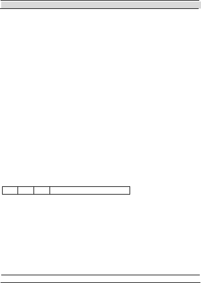
Chapter 8 System Parameters and Commands
- 226 - Hi-G-Tek Ltd. Micro elec tro nics & A sset Tra cking Techno logy
Description The Department ID of the
DataReader.
Remarks
See chapter 6 for further information about the department and organization
IDs concept.
SYS
Property Name (not supported).
Access Read & Write.
Data Type Byte
Constant in
H G TRe a de rP a rame te rCo de En um
HGTHFModemSYS (43h)
Description This value is part of the End of
Header of all RF commands.
Remarks
This value is a bit oriented value that is sent in all the HF RF commands.
The format of this value is as follows:
FP f
754
s p a r e
6 3210
ADIf OIDf
where:
FPf Footprint Flag: if FPf=1, after successful completion of one of the
Verify or Tampered commands, a Footprint (Re a d) Event will be
written in the DataSeal.
ADIf ADI Flag: In an execution of a Command Chain, if ADIf=1 and the
ADI in the DataSeal does not match the ADI in the command (and
it isn't 0), the DataSeal stops listening to the Command Chain.
OIDf OrgID Flag: In an execution of a Command Chain, if OIDf=1 and
the value of the OrgID and Department in the DataSeal does not

Chapter 8 System Parameters and Commands
Hi-G-Tek Ltd. Micro electro nics & Asset Tracking Technology - 227 -
match the OrgID and Department in the command (and they're not
0), the DataSeal stops listening to the Command Chain.
Mode
Property Name Mode
Access Read & Write.
Data Type Byte
Constant in
H G TRe a de rP a rame te rCo de En um
HGTHFModemMode (44h)
Description A bit orient ed value t hat controls
that controls the operation of the
DataReader.
Remarks
DataSealLib also provides several Boolean or enumerated properties that
reflect specific flags of this parameter:
CarrierSense – Determines whether the DataReader will make sure that
the RF is clear before starting transmitting a command. Use this flag when
there are DataReaders that are not connected to the same controlling
computer to avoid RF collisions. In synchronized systems this flag should
be off to ensure that the timings are deterministic.
AllowBurst – Determines whether the DataReader will listen for Burst
messages while it is not executing another RF command. If this flag is on,
you have to check for the Burst messages that the DataReader received
using t he Reader.GetBurstMessages method.
Powe rCali bration Mo de – Because temperature changes affect
t ransmission power, it is required to perform a t emperat ure t est and power
calibration process every once in a while. This property determines the
terms in which the DataReader will perform those operations. See the
online document at ion for further informat ion about the different opt ions.

Chapter 8 System Parameters and Commands
- 228 - Hi-G-Tek Ltd. Micro elec tro nics & A sset Tra cking Techno logy
AutoAckBurst – Determines whether to send an acknowledge message
automatically to every Burst message the DataReader receives. See section
8.5 above for further information about this flag.
AckBurstRandomDelay – Determines whether the DataReader will
choose 1 of 4 windows for the automatic acknowledgment message. See
section 8.5 above for further information about this flag.
Thw
Property Name Thw
Access Read & Write.
Data Type Long. Max value: 65535.
Units 3.072msec.
Default Value 997 (3 seconds).
Constant in
H G TRe a de rP a rame te rCo de En um
HGTHFModemThw (45h )
Description The durat ion of t he Reader
Interrogation Header.
Remarks
See section 8.1.1 for further information about this parameter.
Thp
Property Name Thp
Access Read & Write.
Data Type Long. Max value: 65535.
Units 3.072msec.

Chapter 8 System Parameters and Commands
Hi-G-Tek Ltd. Micro electro nics & Asset Tracking Technology - 229 -
Default Value 3256 (10 seconds).
Constant in
H G TRe a de rP a rame te rCo de En um
HGTHFModemThp (4 6h)
Description The durat ion of t he Reader
Interrogation Header for a Hard
Wakeup command.
Remarks
This parameter is the same as the Th w parameter, but for Hard Wakeup
command.
RS SI
Property Name (not supported).
Access Read-Only.
Data Type Byte
Constant in
H G TRe a de rP a rame te rCo de En um
HGTHFModemRSSI (4 7h)
Description The reception level of the last
message that was received from a
DataSeal.
Remarks
This value may give an approximate estimation about the distance of the
DataSeal from the DataReader.
RF Transm ission Power
Property Name (not supported).
Access Read & Write.

Chapter 8 System Parameters and Commands
- 230 - Hi-G-Tek Ltd. Micro elec tro nics & A sset Tra cking Techno logy
Data Type Byte
Default Value 65
Constant in
HGTReaderPa ram eterCo deEnum
HGTHFModemTransmittionPower
(48h)
Description The nominal value of the RF
transmission power.
Remarks
Using this parameter you can control the DataReader's Receiving Zone.
Internal Version of RF Modem Firmware
Property Name (not supported).
Access Read-Only.
Data Type Byte
Constant in
H G TRe a de rP a rame te rCo de En um
HGTHFModemFirmwareVersion
(48h)
Description The Build number of the firmware
version of the RF Modem.
8.7 Comm and Chain
As ment ioned before, sett ing Th w and Tw to smaller numbers reduces the
response times, but shortens the batteries' lifetime. Even though the default
3 seconds is mostly a reasonable response time, when you have to send
many RF commands, it can accumulate to a lengthily time. The Command
Chain feature allows to execute many RF commands in a row with a single
Reader Interrogation Header (one Th w ). The bat tery consumpt ion of all the
DataSeals that are in Normal Mode (not in Deep Sleep or HF Disabled),
even those that are not addressed by any command in the Chain is exactly

Chapter 8 System Parameters and Commands
Hi-G-Tek Ltd. Micro electro nics & Asset Tracking Technology - 231 -
the same as it would if these commands were executes normally one after
the other, but now that consumption is at a shorter period. However, in
times that there are no transmissions, the battery consumption is normal
(unlike the result of using a small Th w and Tw ).
Commands can also be adde d t o the Command Chain on t he go, when you
want to perform a command as a result of the response or responses that
you received in a previous command. For example, suppose that you want
to perform a Set command to all the DataSeals that their User Parameter 1
contains the string "READY". You can do it by initiating a Command
Chain with only a broadcast Ve rif y command that asks for the User
Parameter 1 parameter, and after receiving the results and examining the
cont ent of the Use r Pa rame te r 1 parameter, you add the Set command
with the list of Seal ID's of those DataSeals that their User Parameter 1
parameter contain the string "READY".
Note that all the DataSeals that receive the Reader Interrogation Header of
a Command Chain keep listening to all the commands, which consumes
battery as if these commands were executed one after the other. For
DataSeals that there are no command for them it means a waste of battery.
There are few things that you can do to avoid it:
1. Make sure that the DataSeals that should not receive the commands in
the Chain are either in Deep Sleep, but usually more appropriate, their
HF Disabled flag is on (for example by using the Sleep Duration
argument of t he Ve ri fy command).
2. If t here are Dat aSeals wit h different OrgIDs or Depart ment s, and you
want to turn only to one of them, you should turn on the OIDf flag in
the DataReader's SYS parameter.
3. If there are DataSeals with different ADIs, and want to turn only to a
specific group, you should turn on the ADIf flag in the DataReader's
SYS parameter.

Chapter 8 System Parameters and Commands
- 232 - Hi-G-Tek Ltd. Micro elec tro nics & A sset Tra cking Techno logy
For more information about Command Chains see the description of the
CommandChain class in the online documentation.

Chapter 9 Troubleshooting and Problem Solving
- 234 - Hi-G-Tek Ltd. Micro elec tro nics & A sset Tra cking Techno logy
9 Trouble Shooting and Problem Solving
9.1 General DataReader Problems
1. Power LED is red: The DataReader is malfunctioning. Replace the
DataReader.
2. Power LED is off: Check the power connection.
9.2 RS-232/485 Comm unication Problems
3. DataReader does not respond to the controlling computer:
Verify t hat t he Power LED blinks during power on. The LED
should then remain steadily green.
Verify that the cables are connected according to the diagrams in
chapter 5.
Verify that the Reader ID you specified is the same number as the
S/N printed on the sticker on the back side of the DataReader
(below the barcode).
Verify that a terminator exists at end of the RS-485 chain, as
described in chapt er 5.
Make sure that the specified COM port is the COM port that in fact
the DataReader is connected to.
9.3 General RF Comm unication Problems
4. DataReader does not receive a specific DataSeal:
Verify that the DataSeal is within the DataReader's Receiving
Zone. Check that the RF Transmission Powe r parameter is not too

Chapter 9 Troubleshooting and Problem Solving
Hi-G-Tek Ltd. Micro electro nics & Asset Tracking Technology - 235 -
low. Putting the DataSeal too close to the DataReader's antenna
(few cent imet ers) may causes signal dist ort ions.
Verify that the ant enna is connect ed properly.
Verify that the SD/RD LED of Channel 2 is red for a about 3
seconds (with default Th w ) upon receiving the command from the
controlling computer, and then turns green for a short time.
The DataSeal may be in Deep Sleep mode. Try to execute a Hard
Wakeup command.
Make sure that the ADI an d Department parameters in the
DataReader are either 0 or the same values that should be in the
DataSeal.
If you can communicate with the DataSeal using a Low Frequency
dev ice ( Dat aT erm in al or Dat aP ort ), mak e sur e th at t h e ADI,
OrgID an d De partme n t parameters match those of the
DataReader. Also make sure that Tw is appropriate for the Th w in
the DataReader. See chapter 8 for information about Th w and Tw .
Mak e sure th at t h e HF Disabled flag is off too.
The Ve ri fy parameters are invalid. See chapter 8 for information
about the parameters of the Verify command.
9.4 Specific RF commands troubleshooting:
5. Dat aSeal does not respond to a Tampered command:
The DataSeal is not tampered. Check the DataSeal's Tampered
flag.
6. Dat aSeal does not respond to a Hard Wakeup co mm an d:
The DataSeal may already be waked up (in Normal mode). Check
the DataSeal's Deep Sleep flag.
7. Set/Reset Status command fails:

Chapter 9 Troubleshooting and Problem Solving
- 236 - Hi-G-Tek Ltd. Micro elec tro nics & A sset Tra cking Techno logy
On or more of the specified flags may be read-only.
8. Write Parameters command fails:
One or more of the specified parameters may be read-only.
The data type or the parameter size of one or more parameters are
invalid.

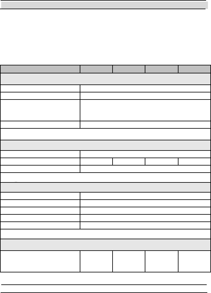
Chapter 10 Technical Specifications
- 238 - Hi-G-Tek Ltd. Micro elec tro nics & A sset Tra cking Techno logy
10 Technical Specifications
10.1 RS485 24V Outdoor DataReader
24V Outdoor DataReader IG-RS-46D-916 IG-RS-46D-433 IG-RS-46D-318 IG-RS-46D-315
Physical Characteristics
Dimensions 195x165x95mm, not including antenna
Weight 1000gr
Power requirements –
External
Nominal - 24VDC
Mini mum – 10VDC
Maximum – 35VDC
Power Consumption 1.7W @Tx, 1.1W@Rx
Performance Characteristics
Interface RS485 optically isolated
Operating frequency [MHz] 916.5 433.92 318 315
Read Range 30m @ open space
Environmental Conditions
Operating Temperature -40ºC — 70ºC
Storage Temperature -40ºC — 70ºC
Humidity 90% Non condensing
Mechanical Vibration As per MIL-810D & SAE J1455
Mechanical Shock As per MIL-810D & SAE J1455
Standards
Designed according to FCC par
t
15C
UL1950
EN300220
EN301489
EN60950
UL1950
UL1950
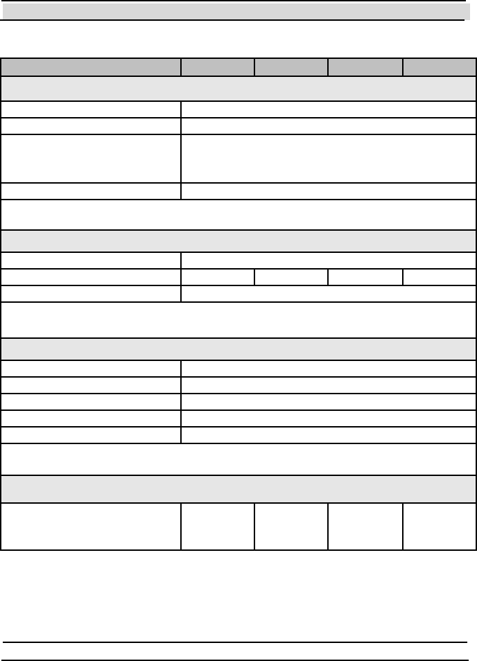
Chapter 10 Technical Specifications
Hi-G-Tek Ltd. Micro electro nics & Asset Tracking Technology - 239 -
10.2 RS232, 24V Outdoor DataReader
24V Outdoor DataReader IG-RS-43D-916 IG-RS-43D-433 IG-RS-43D-318 IG-RS-43D-315
Physical Characteristics
Dimensions 195x165x95mm, not including antenna
Weight 1000gr
Power requirements –
External
Nominal - 24VDC
Mini mum – 10VDC
Maximum – 35VDC
Power Consumption 1.7W @Tx, 1.1W@Rx
Performance Characteristics
Interface RS232
Operating frequency [MHz] 916.5 433.92 318 315
Read Range 30m @ open space
Environmental Conditions
Operating Temperature -40ºC — 70ºC
Storage Temperature -40ºC — 70ºC
Humidity 90% Non condensing
Mechanical Vibration As per MIL-810D & SAE J1455
Mechanical Shock As per MIL-810D & SAE J1455
Standards
Designed according to FCC
part 15C
UL1950
EN300220
EN301489
EN60950
UL1950
UL1950
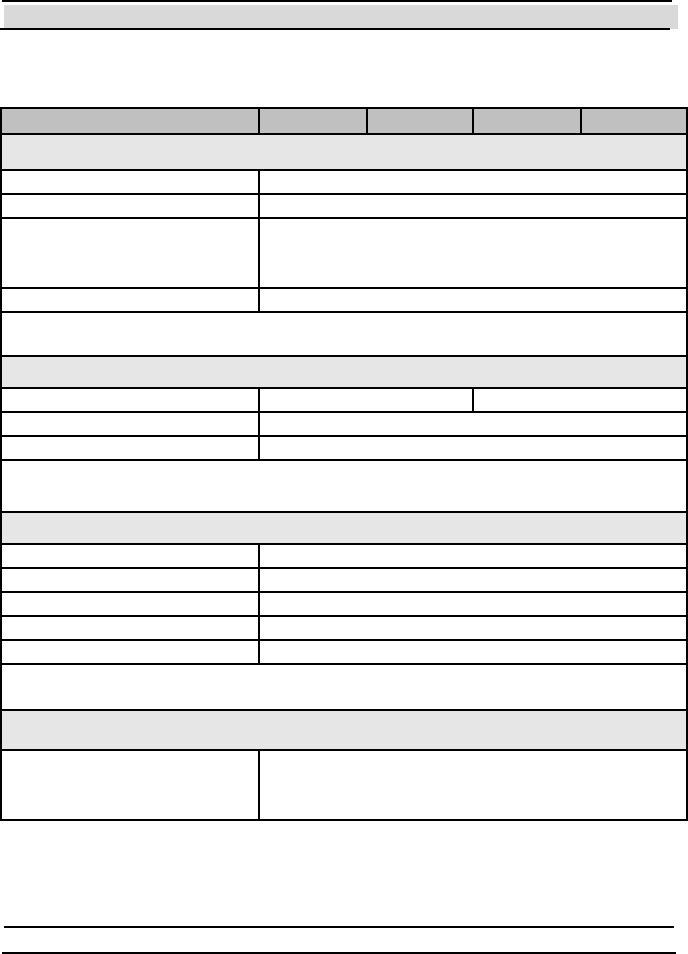
Chapter 10 Technical Specifications
- 240 - Hi-G-Tek Ltd. Micro elec tro nics & A sset Tra cking Techno logy
10.3 Specific- 24V Outdoor DataReader
24V Outdoor DataReader IG-RS-46D9-916 IG-RS-43D9-916
Physical Characteristics
Dimensions 195x165x95mm, not including antenna
Weight 1000gr
Power requirements –
External
Nominal - 24VDC
Mini mum – 10VDC
Maximum – 35VDC
Power Consumption 1.7W @Tx, 1.1W@Rx
Performance Characteristics
Interface RS485optically isolated RS232
Operating frequency [MHz] 916.5
Read Range Antenna dependant
Environmental Conditions
Operating Temperature -40ºC — 70ºC
Storage Temperature -40ºC — 70ºC
Humidity 90% Non condensing
Mechanical Vibration As per MIL-810D & SAE J1455
Mechanical Shock As per MIL-810D & SAE J1455
Standards
Designed according to FCC part 90, FCC part 15B
UL1950
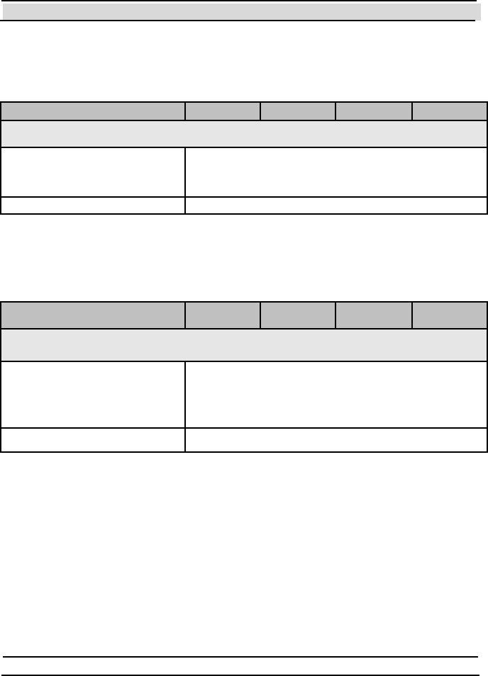
Chapter 10 Technical Specifications
Hi-G-Tek Ltd. Micro electro nics & Asset Tracking Technology - 241 -
10.4 12V Outdoor DataReader
12V Outdoor DataReader IG-RS-26D-916 IG-RS-26D-433 IG-RS-26D-318 IG-RS-26D-315
Physical Characteristics
Power requirements –
External
Nominal - 12VDC
Mini mum – 10VDC
Maximum – 35VDC
Power Consumption 1.7W @Tx, 1.1W@Rx
* All other specifications are as in section 10.1.
10.5 48V Outdoor DataReader
48V Outdoor DataReader IG-RS-86D-916 IG-RS-86D-433 IG-RS-86D-318 IG-RS-86D-315
Physical Characteristics
Power requirements –
External
Nominal - 48VDC
Mini mum – 20VDC
Maximum – 70VDC
Power Consumption 1.7W @Tx, 1.1W@Rx
All other specifications are as in section 10.1.
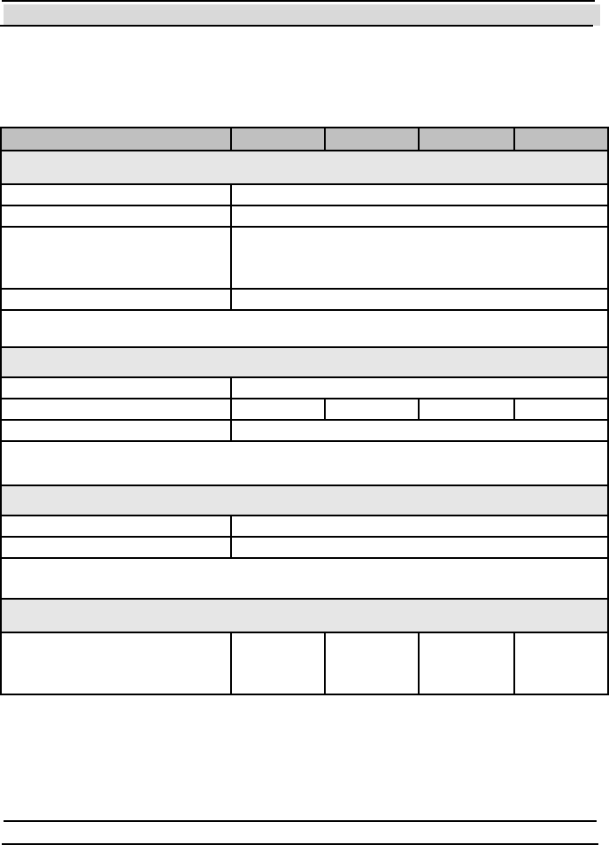
Chapter 10 Technical Specifications
- 242 - Hi-G-Tek Ltd. Micro elec tro nics & A sset Tra cking Techno logy
10.6 24V Indoor DataReader
24V Indoor DataReader IG-RS-46-916 IG-RS-46-433 IG-RS-46-318 IG-RS-46-315
Physical Characteristics
Dimensions 195x165x95mm, not including antenna
Weight 1000gr
Power requirements –
External
Nominal - 24VDC
Mini mum – 10VDC
Maximum – 35VDC
Power Consumption 1.7W @Tx, 1.1W@Rx
Performance Characteristics
Interface RS485 optically isolated
Operating frequency [MHz] 916.5 433.92 318 315
Read Range 30m @ open space
Environmental Conditions
Operating Temperature 0ºC — 70ºC
Storage Temperature -20ºC — 70ºC
Standards
Designed according to FCC part
15.249
UL1950
EN300220
EN301489
EN60950
UL1950
UL1950
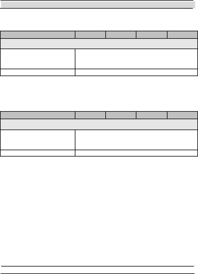
Chapter 10 Technical Specifications
Hi-G-Tek Ltd. Micro electro nics & Asset Tracking Technology - 243 -
10.7 12V Indoor DataReader
12V Indoor DataReader IG-RS-26-916 IG-RS-26-433 IG-RS-26-318 IG-RS-26-315
Physical Characteristics
Power requirements –
External
Nominal - 12VDC
Mini mum – 10VDC
Maximum – 35VDC
Power Consumption 1.7W @Tx, 1.1W@Rx
* All other specifications are as in section 10.6.
10.8 48V Indoor DataReader
48V Indoor DataReader IG-RS-86-916 IG-RS-86-433 IG-RS-86-318 IG-RS-86-315
Physical Characteristics
Power requirements –
External
Nominal - 48VDC
Mini mum – 20VDC
Maximum – 70VDC
Power Consumption 1.7W @Tx, 1.1W@Rx
* All other specifications are as in section 10.6.
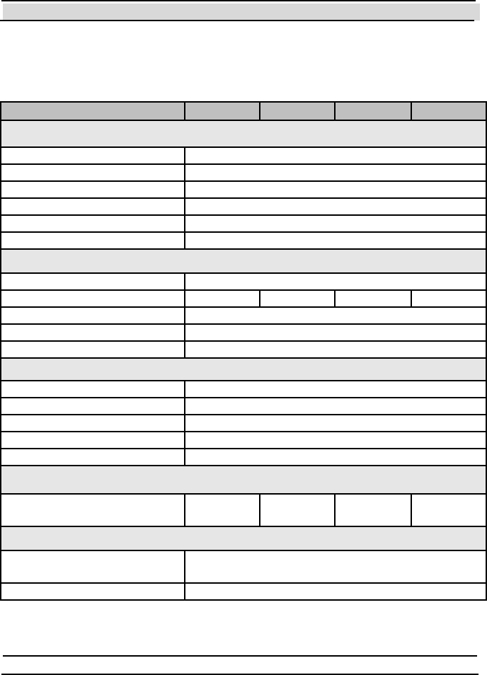
Chapter 10 Technical Specifications
- 244 - Hi-G-Tek Ltd. Micro elec tro nics & A sset Tra cking Techno logy
10.9 DataSeal
DataSeal IG-RS-40-916 IG-RS-40-433 IG-RS-40-318 IG-RS-40-315
Physical Characteristics
Dimensions 49x37x35mm
Weight 100gr
Housing P la sti c rei n force d wi th fi be rgl a ss
Power Internal 3.6V battery
User Memory 2048 bytes
Ev ents Memory 55
Performance Characteristics
Interface Mounting cradle p/n IG-DH-40
Operating frequency [MHz] 916.5 433.92 318 315
Read Range 30m @ open space
Operating frequency 125KHz
Read Range 50cm
Environmental Conditions
Operating Temperature -40ºC — 70ºC
Storage Temperature -40ºC — 70ºC
Humidity 90% non condensing
Mechanical Vibration As per MIL-810D & SAE J1455
Mechanical Shock As per MIL-810D & SAE J1455
Standards
Designed according to FCC part
15.249
EN300220
EN301489
Antenna Characteristics
Beam Divergence Omni-directional on non-metal wall.
Hemisphere on metal wall.
Polarization Vertical
Chapter 10 Technical Specifications
Hi-G-Tek Ltd. Micro electro nics & Asset Tracking Technology - 245 -
10.10 Magnetic DataSeal
Magnetic DataSeal IG-RS-40M-916 IG-RS-40M-433 IG-RS-40M-318 IG-RS-40M-315
Physical Characteristics
Dimensions 49x37x35mm
Weight 100gr
Housing P la sti c rei n force d wi th fi be rgl a ss
Power Internal 3.6V battery
User Memory 2048 bytes
Ev ents Memory 55
Performance Characteristics
Operating frequency [MHz] 916.5 433.92 318 315
Read Range 30m @ open space
Operating frequency 125KHz
Read Range 50cm
Environmental Conditions
Operating Temperature -40ºC — 70ºC
Storage Temperature -40ºC — 70ºC
Humidity 90% non condensing
Mechanical Vibration As per MIL-810D & SAE J1455
Mechanical Shock As per MIL-810D & SAE J1455
Standards
Designed according to FCC part
15.249
EN300220
EN301489
Antenna Characteristics
Beam divergence Omni-directional on non-metal wall.
Hemisphere on metal wall.
Polarization Vertical
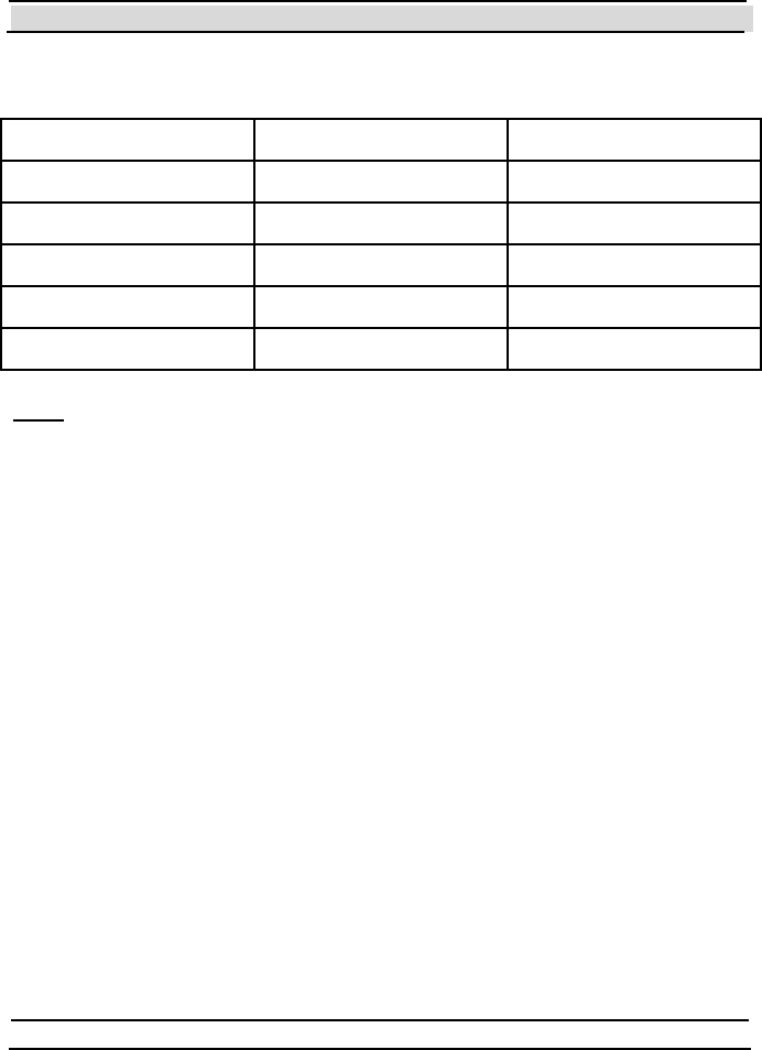
Chapter 10 Technical Specifications
- 246 - Hi-G-Tek Ltd. Micro elec tro nics & A sset Tra cking Techno logy
10.11 FCC approved products:
Product P/N FCC ID
DataReader IG-RS-46D-916 OB6-IGR46D916
DataSeal IG-RS-40-916 OB6-IGRS40916
DataTag IG-DT-40-916 OB6-IGDT40916
DataReader IG-RS-46D9-916 OB6-IGRS46D9916
DataReader IG-RS-43D9-916 OB6-IGRS46D9916
Note: T his equipment has been tested and found to comply with the limits
for a Class B digital device, pursuant to part 15 of the FCC Rules. These
limits are designed to provide reasonable protection against harmful
interference in a residential installation. This equipment generates, uses and
can radiat e radio frequency energy and, if not inst alled and used in
accordance with the instructions, may cause harmful interference to radio
communications. However, there is no guarantee that interference will not
occur in a particular installation. If this equipment does cause harmful
interference to radio or television reception, which can be determined by
turning the equipment off and on, the user is encouraged to try to correct
the interference by one or more of the following measures:
Reorient or relocate the receiving antenna.
Increase the separation between the equipment and receiver.
Connect the equipment into an outlet on a circuit different from that to
which the receiver is connected.
Consult the dealer or an experienced radio/TV technician for help.
Changes or modifications to this equipment not expressly approved by
Hi-G-T ek Ltd. could void t he user’s aut hority to operat e the equipment.

Chapter 10 Technical Specifications
Hi-G-Tek Ltd. Micro electro nics & Asset Tracking Technology - 247 -
Warning:For unlicensed transmitters approved according to FCC part 15
subp art C, it is the responsibility of the installer to ensure that when using
the outdoor antenna kits in the United States (or where FCC rules apply),
only those antennas certified with the product are used. T he use of any
ant enna other than those cert ified wit h the product is expressly forbidden in
accordance with FCC rules CFR47 part 15.204.”


Chapter 10 Technical Specifications
- 250 - Hi-G-Tek Ltd. Micro elec tro nics & A sset Tra cking Techno logy
11 INDEX
1
12v Indoor DataReader 242
12v Outdoor DataReader 241
2
24v Indoor DataReader 241
24v Outdoor DataReader 240
4
48v Indoor DataReader 243
48v Outdoor DataReader 241
A
Accelerate Verify (RF Command) 181
Accelerated Verify Mode (Status flag) 181, 197
Acknowledge Alert Burst (RF Command) 85, 123, 212
Acknowledge Close Burst (RF Command) 212
Acknowledge Forced Burst (RF Command) 212
Address (DataReader Parameter) 219
Addressed Commands 136, 197
Add ress ed Veri fy (RF C omm an d) 32, 8 6, 95, 9 6, 98, 9 9, 10 0, 107, 13 9, 197
ADI 79, 80, 96, 189, 227, 228, 233
DataReader Parameter 226, 237
DataSeal Parameter 139
Alert and Close Burst P eriod (DataS eal Parameter) 140, 213
Alert Burst
B urs t M es sage 15 5, 179, 210, 216
M ode 69, 7 0, 85, 1 20, 122, 194, 2 05, 211
Alert Burst Data Descriptor (DataSeal Parameter) 140, 215
Al ert Burst M ode (St atus flag ) 17 8, 194, 210, 211
Alert Burst Period (DataSeal Parameter) 155
Analog Values (DataReader Parameter) 220

Index
Hi-G-Tek Ltd. Micro electro nics & Asset Tracking Technology - 251 -
Application Flags (DataSeal Parameter) 141, 210
Approve Open (RF Command) 72, 86, 173, 188, 198
Approved Open
Event 188, 199
S tat us fl ag 72, 73, 86, 1 72, 173, 198, 2 08
B
Battery Voltage Value (DataSeal Parameter) 142, 154
Baud Rate 92
BIT Period (DataSeal Parameter) 143
BMM See Broadcast Commands
BMM List See Mu lt i Add ressed C omm ands
Broadcast Commands 136
Broadcast Verify (RF Command) See V er i fy (R F Com m and )
Buffer Full (Status flag) 179
Built-In Test 126
Built-in Test Period (DataReader Parameter) 220
Burst Messages 14, 148, 212
Burst Mode See A lert B u rst M ode
Burst Mode (Status flag) See A l ert B u rs t M od e (S t at us fl a g )
Burst R eceiving M ode (DataReader) 70
C
Cables 60
Calibration Message Window 192
Carrier Sense 70, 75
Cellular Layout 75
Chain
of Commands See Comm and C hai n
RS-485 53, 76
Chain NOP Count (DataReader Parameter) 226
Chain NOP Interv al (DataReader Parameter) 225
Close Burst (Burst Message) 155, 178, 213, 217
Close Burst Data Descriptor (DataSeal Parameter) 143, 215
Close Burst Mode (Status f lag) 178, 213
Closed (Event) 82
C ommand Ch ain 189, 190, 207, 225, 226, 228, 232, 233
Command Failed (Status f lag) 177
CommandChain (DataSealLib Class) 233

Chapter 10 Technical Specifications
- 252 - Hi-G-Tek Ltd. Micro elec tro nics & A sset Tra cking Techno logy
D
Database Corrupted
Status flag 172
Database Corrupted (Status flag) 175
Database Corrupted and Restored
Event 185
Status flag 174
Database Error
S tat us flag 17 2, 174, 208
Dat aPo rt 1 2, 13, 14, 67, 18 2, 218, 237
DataReader 14
Ins tall ation 4 4
DataSeal 12, 243
Ins tall ation 3 6
DataSeal Evaluation Software See Evaluation Software
Dat aS eal Lib (C OM DLL ) 84, 1 02, 134, 182, 1 88, 189, 195, 2 07, 214, 215, 2 17, 219, 229
DataTag 12, 13, 22, 26, 28, 40, 41, 66
Ins tall ation 4 0
P lacin g on a Vehi cle 4 0
Dat aT erm inal 12, 1 3, 14, 6 6, 67, 6 8, 69, 70, 83, 182, 2 18, 237
Date & Time (DataSeal Parameter) 14 4, 149, 151, 156, 158, 18 6
Date & Time (Parameter) 186
Date & Time Updated (Ev ent) 186
Deep S leep
Burst 145
Burst Message 155
Event 210
M ode 26, 69, 73, 1 19, 166, 172, 1 88, 208, 209, 2 10, 211, 2 32, 2 33
RF C omm and 85, 118, 1 42, 188, 210, 2 16
S tat us fl ag 73, 171, 2 10, 211, 237
Deep Sleep Burst (Burst Message) 216
Deep Sleep Burst Period (DataSeal Parameter) 145, 156, 213
Deep Sleep Mode (Event) 188
Demo System 22
Department 78, 80, 96, 160, 176, 233
DataReader Parameter 227, 237
DataSeal Parameter 79, 80, 145
Distance Index (DataSeal Parameter) 146

Index
Hi-G-Tek Ltd. Micro electro nics & Asset Tracking Technology - 253 -
E
Evaluation Software 23, 90
Ins tall ation 9 0
Ev ent Counter Value (DataSeal Parameter) 146
Events 31, 69
Events (DataSealLib Class) 200
Ev en ts M emory6 9, 71, 81, 82, 85, 86, 124, 158, 159, 160, 180, 181, 183, 185, 199, 20 8, 243,
244
Extended Alert Burst (Burst Message) 179
F
Firmware Version (DataSeal Parameter) 147, 149
Flags (DataSeal Parameter) 148, 213
F ootp rint 69, 165, 1 66, 186, 228
Footprint (Ev ent) See R ead (Event)
F ootp rint E ven ts Mode 69
Forced Burst 86, 204
F orced B urs t (Bu rst M ess age) 20 4, 205, 213, 215, 217
Forced Burst (Burst Message) 204
G
General Error (Status flag) 73, 172
Global (DataSeal Parameter) 79, 80, 149
GPS 14
GSM 14
H
Hard W akeup (RF Comm and ) 26, 2 7, 28, 32, 69, 8 5, 11 9, 166, 188, 21 0, 211, 230, 231, 237
Hardware Error (Status flag) 172, 176
HF See High Frequency
HF Disabled (Status f lag) See High Frequency Disabled
HGT SealP aram eterC odeEn um (Dat aS ealLib En um eratio n ) 13 9, 20 1, 203
HGT V erify M askE num (D at aS ealLi b Enum erati on) 13 9, 14 1, 144, 191, 197, 204, 20 6
High Frequency 13, 14, 134, 168
High Frequency Disabled (Status flag) 18 0, 199, 233, 237

Chapter 10 Technical Specifications
- 254 - Hi-G-Tek Ltd. Micro elec tro nics & A sset Tra cking Techno logy
I
Illegal OrgID (Status flag) 78, 172, 176
Indoor DataReader 19, 49, 59
Inputs (DataReader Parameter) 223
Internal Firmware Version (DataSeal Parameter) 150
Internal Version of Loader Firmware (DataReader Parameter) 223
Internal Version of MCU Firmware (DataReader Parameter) 222
Internal Version of RF Modem Firmware (DataReader Parameter) 232
L
Last Date & Time Update (DataSeal Parameter) 151
Last Set Reader ID (DataSeal Parameter) 151, 208, 209
LFSee Low Frequency
Lif e Counter (DataSeal Parameter) 15 2, 173, 208, 209
L i fe C ou nt er 0 (S t at us fl a g ) 1 7 2, 17 3
Loader Firmware Version (DataReader Parameter) 222
Long Event 182
Long Events 126
Lon g S tat us (D at aS eal P aram eter) 7 2, 73, 78, 8 2, 86, 9 6, 98, 1 00, 109, 1 52, 1 64, 169, 1 72,
19 7, 205, 206, 211, 213
Low Battery Error (Status flag) 1 43, 153, 154, 172, 174, 184, 208, 209
Low B at tery E rro r Thres ho ld (D ataS eal P aram eter) 1 43, 153, 154, 174
Low Battery Warning
Event 183
S tat us flag 16 9, 208, 209
L ow B at t ery W arn in g (S t at us fl ag ) 7 2, 1 54
Low B att ery W arn ing T hreshol d (DataS eal P aram et er) 14 3, 15 4, 17 0, 18 4
Low Frequency 13
M
MagneticDataSeal 12, 13, 66, 244
Maximal Alert and Close Burst Retries (DataSeal Parameter) 155, 213
Maximal Deep Sleep Burst Retries (DataSeal Parameter) 155
Maximal Deep Sleep Burst Retries (DataSeal Parameters) 213
Maximal Difference in Time Update (DataSeal Parameter) 156, 158
Maximal Message Size (DataSeal Parameter) 157, 179
Maximal Number of Events (DataSeal Parameter) 159, 160, 164
Maximal Number Of Events (DataSeal Parameter) 157
Maximal Threshold for MCU Voltage Checking (DataReader Parameter) 221

Index
Hi-G-Tek Ltd. Micro electro nics & Asset Tracking Technology - 255 -
Maximal Threshold for RF Modem Voltage Checking (DataReader Parameter) 222
MaxTimeDiffUpdate (DataSealLib Property) 156
MC U 62, 9 3, 12 7, 130, 218, 22 0, 223
MCU Firmware Version (DataReader Parameter) 218
MicroDataReader 12, 13, 14, 66, 68, 218
Minimal Interval between Time Updates (DataSeal Parameter) 156, 158
Minimal Threshold f or MCU Voltage Checking (DataReader Parameter) 221
Minimal Threshold f or RF Modem Voltage Checking (DataReader Parameter) 221
Mode
DataReader Parameter 148
Mode (DataReader Parameter) 228
Mounting Fixture 15, 16, 36
M oxa T ech no lo gi es 56
Multi Addressed Commands 136
Multi Addressed Verify (RF Command) 86, 136, 139, 206
N
New Battery
Status flag 175
NOP (RF Command) 189
Normal Mode See Operation Mode
Number of Events (DataSeal Parameter) 149, 158, 160
Number of Events (DataSeal Paramter) 158
Number of Scroll Events (DataSeal Parameter) 159
O
Opened
Event 82
S tat us flag 31, 7 2, 109, 170, 173, 208, 20 9
Operation Mode 68
Org ID 78, 7 9, 80, 96, 14 9, 160, 176, 181, 228, 233
DataReader Parameter 219, 237
OrgID & Department (DataSeal Parameter) 160
Outdoor DataReader 17, 44, 46, 59
Outputs (DataReader Parameter) 224
P
Param eters
DataSeal 31, 138

Chapter 10 Technical Specifications
- 256 - Hi-G-Tek Ltd. Micro elec tro nics & A sset Tra cking Techno logy
Power LED 62, 236
Power Supply 58
R
Random Windows 192
Read (Event) 166, 186, 228
Read Data (RF Command) 82, 85, 110, 179, 200
Read Events (RF Command) 86, 124, 179, 199
Read Multi Access Data (RF Command) 82, 202
Read Parameters (RF Command) 86, 114, 138, 150, 179, 201
Reader (DataSealLib Class) 188, 217
Reader Address (DataReader Parameter) 218
Reader ID (DataReader Parameter) 218
Reader Interlace Window 192
R eader Int erro gat io n H ead er 13 4, 135, 136, 215, 23 0, 232, 233
Reader Reset Timeout (DataReader Parameter) 224
Reader.AccelerateVerify (DataSealLib M ethod) 195
Reader.AckBurstRandomDelay (DataSealLib Property) 213, 229
Reader.Address (DataSealLib Property) 218
Reader.ADI (DataSealLib Property) 226
R eader.All owB urs t (Dat aS eal Lib P roperty ) 21 3, 229
Reader.AutoAckBurst (DataSealLib Method) 213
Reader.AutoAckBurst (DataSealLib Property) 229
Reader.BurstEx (DataSealLib Event) 215
Reader.CarrierSense (DataSealLib Property) 229
Reader.ChainNopCount (DataSealLib Property) 226
Reader.ChainNopInterval (DataSealLib Property) 225
Reader.DryContact (DataSealLib Property) 224
Reader.ExternalInterruptInput (DataSealLib Property) 223
Reader.ExternalLEDOutput (DataSealLib Property) 224
Reader.GetBurstMessages (DataSealLib Method) 213, 214, 229
Reader.Inputs (DataSealLib Property) 223
Reader.IsolatedInput (DataSealLib Property) 223
Reader.IsolatedOutput1 (DataSealLib Property) 224
Reader.IsolatedOutput2 (DataSealLib Property) 224
Reader.Mode (DataSealLib Property) 228
Reader.NOP (DataSealLib Method) 189
Reader.Outputs (DataSealLib Property) 224
Reader.PowerCalibrationMode (DataSealLib Property) 229
Reader.ReaderID (DataSealLib Property) 218
Reader.ReadParameter (DataSealLib Method) 217

Index
Hi-G-Tek Ltd. Micro electro nics & Asset Tracking Technology - 257 -
Reader.SetAsyncAlertBurstMode (DataSealLib Method) 194
Reader.Thp (DataSealLib Property) 230
Reader.Thw (DataSealLib Property) 230
Reader.Verify (DataSealLib Method) 139, 190
Reader.WriteParameter (DataSealLib Method) 217
Real Time Clock Error (Status flag) 172, 174
Real Time Clock Stopped (Event) 185
R eceivi ng Z one 71, 7 6, 79, 8 6, 13 7, 19 0, 197, 206, 232, 236
Reset Data (RF Command) 86, 117, 210
RF M od em 6 2, 93, 127, 130, 131, 220, 226, 232
RF Modem Firmware Version (DataReader Parameter) 226
RF Transmission Power (DataReader Parameter) 231, 236
RFCommandObject (DataSealLib Class) 189
RFP aram et ers (D ataS ealLib C las s) 1 3 8, 14 6, 19 1, 19 2, 197, 206
RFParameters.DefaultsFor (DataSealLib Method) 138
RFParameters.T cm (DataSealLib Property) 146
RS -232 14, 1 8, 46, 47, 49, 5 0, 51, 53, 56, 5 8, 67, 74, 77, 9 1, 13 4, 225, 236
Wiring Diagram 47, 51
RS-232/RS-485 Adapter 56
RS -485 15, 4 6, 48, 49, 50, 5 2, 53, 54, 56, 5 8, 60, 74, 76, 9 1, 21 9, 236
Full Duplex 46, 48, 50, 52
Half Duplex 46, 48, 50, 53
RSSI
DataSeal Parameter 160
RSSI (DataReader Parameter) 231
RTC Error (Status flag) 174
RTC Stopped (Ev ent) See Real Time Clock Stopped (Event)
S
S cro ll (St atu s fl ag ) 8 2, 1 58, 1 79
S croll able Po rti on 15 9, 180
SD/RD LED 62, 63, 237
S eal (D at aS ealLib Cl ass) 1 53, 188, 191, 198, 207
Seal ID (DataSeal Parameter) 161
S eal St am p (D ataS eal P aram et er) 10 0, 109, 149, 162, 163, 18 2
Seal.ADI (DataSealLib Property) 139
Seal.AlertBurstDataDescriptor (DataSealLib Property) 140
Seal.AlertBurstMode (DataSealLib Property) 178
Seal.AlertBurstPeriod (DataSealLib Method) 140
Seal.ApplicationFlags (DataSealLib Property) 141
Seal.ApprovedOpen (DataSealLib Property) 172

Chapter 10 Technical Specifications
- 258 - Hi-G-Tek Ltd. Micro elec tro nics & A sset Tra cking Techno logy
Seal.ApproveOpen (DataSealLib Method) 198
Seal.BatteryVoltageValue (DataSealLib Property) 142
Seal.BITPeriod (DataSealLib Property) 143
Seal.BufferFull (DataSealLib Property) 179
Seal.CloseBurstDataDescriptor (DataSealLib Property) 143
Seal.CloseBurstMode (DataSealLib Property) 178
Seal.CloseBurstPeriod (DataSealLib Method) 140
Seal.CommandFailed (DataSealLib Property) 177
Seal.DateTime (DataSealLib Property) 144
Seal.DBCorrupted (DataSealLib Property) 175
Seal.DBCorruptedAndRestored (DataSealLib Property) 174
Seal.DeepSleep (DataSealLib Property) 171
Seal.DeepSleepBurstPeriod (DataSealLib Property) 145
Seal.Department (DataSealLib Property) 145
Seal.DistanceIndex (DataSealLib Property) 146
Seal.EventCounterValue (DataSealLib Property) 146
Seal.EventsCount (DataSealLib Property) 158
Seal.FirmwareVersion (DataSealLib Property) 147
Seal.Flags (DataSeal Parameter) 148
Seal.FormatB (DataSealLib Property) 161
Seal.GeneralError (DataSealLib Property) 172
Seal.HardwareError (DataSealLib Property) 176
Seal.HFDisabled (DataSealLib Property) 180
Seal.IllegalOrgID (DataSealLib Property) 176
Seal.InternalFirmwareVersion (DataSealLib Property) 150
Seal.LastDateTimeUpdate (DataSealLib Property) 151
Seal.LastSetReader (DataSealLib Property) 151
Seal.LifeCounter (DataSealLib Property) 152
Seal.LifeCounterZero (DataSealLib Property) 173
S eal.Lon gStatu s (D ataS eal Lib P roperty ) 15 2, 20 7
Seal.LowBatteryError (DataSealLib Property) 174
Seal.LowBatteryErrorThreshold (DataSealLib Property) 153
Seal.LowBatteryWarning (DataSealLib Property) 169
Seal.LowBatteryWarningThreshold (DataSealLib Property) 154
Seal.MaxAlertBurstRetries (DataSealLib Property) 155
Seal.MaxDeepSleepBurstRetries (DataSealLib Property) 155
Seal.MaxMessageSize (DataSealLib Property) 157
Seal.MaxNumberOfEvents (DataSealLib Property) 157
Seal.MinIntervalBetweenTimeUpdates (DataSeal Property) 158
Seal.NewBattery (DataSealLib Property) 175
Seal.NumberOfScrollEvents (DataSealLib Property) 159
Seal.Opened (DataSealLib Property) 170

Index
Hi-G-Tek Ltd. Micro electro nics & Asset Tracking Technology - 259 -
Seal.OrgID (DataSealLib Property) 160
Seal.OrgIDBurst (DataSealLib Property) 181
Seal.ReadData (DataSealLib Method) 200
Seal.ReadEvent (DataSealLib Method) 199
Seal.ReadMultiAccessData (DataSealLib Method) 202
Seal.ReadParam eter (DataS ealLib Method) 139, 201
Seal.ReadParam eters (DataS ealLib Method) 139, 201
Seal.ResponseMask (DataSealLib Property) 215
Seal.RSSI (DataSealLib Property) 160
Seal.RTCError (DataSealLib Property) 174
Seal.SealID (DataSealLib Property) 161
Seal.SealStamp (DataSealLib Property) 162
Seal.SealWireChanged (DataSealLib Property) 171
Seal.SetStatus (DataSealLib Method) 153, 205
Seal.ShortStatus (DataSealLib Property) 163, 207
Seal.SleepDurationUnit (DataSealLib Property) 164
Seal.StartForcedBurst (DataSealLib Method) 203
Seal.SuspendedSet (DataSealLib Property) 170
Seal.Tampered (DataSealLib Property) 169
Seal.TempDisableHF (DataSealLib Method) 199
Seal.TimeFilterForReadEvent (DataSealLib Property) 165
Seal.Tp (DataSealLib Property) 166
Seal.Ts (DataSealLIb Property) 167
Seal.Tw (DataSealLib Property) 167
Seal.UnrecognizedCommand (DataSealLib Property) 177
Seal.UserData (DataSealLib Property) 149
Seal.UserDataSize (DataSealLib Property) 164
Seal.UserParameter1 (DataSealLib Property) 168
Seal.UserParameter2 (DataSealLib Property) 168
Seal.Verify (DataSealLib Method) 139, 197
Seal.WriteData (DataSealLib Method) 202
Seal.WriteParameter (DataSealLib Method) 139, 203
Seal.WriteParameters (DataSealLib Method) 139, 203
SealCodesAndValues (DataSealLib Class) 201, 203
SealEvent (DataS ealLib Class) 182, 200
Sealing Wire 13, 17
Sealing Wire Changed
Event 183
Status flag 171
Sealing Wire Changed (Status flag) 73, 208, 209
Sealing Wire Closed (Ev ent) 184
Sealing Wire Opened (Ev ent) 184

Chapter 10 Technical Specifications
- 260 - Hi-G-Tek Ltd. Micro elec tro nics & A sset Tra cking Techno logy
S eals (D at aS ealLib C las s ) 1 88, 191, 207
Seals.AckBurst (DataSealLib Method) 212
Seals.DeepSleep (DataSealLib Method) 210, 211
Seals.ResetDataBlock (DataSealLib Method) 210
Seals.SealSet (DataSealLib Method) 207, 208, 209
Seals.SetAsyncAlertBurstMode (DataSealLib Method) 211
S eal s. V eri fy (D a t aS e al Li b M e th od ) 1 3 9, 20 6
SealStamp (DataSealLib Property) 207
Send OrgID in Burst (Status f lag) 181
S ensor Pl ate 13, 22, 28, 4 0
Set
Event 82, 183
RF C omm an d 1 4, 32, 69, 71, 85, 95, 10 0, 108, 152, 162, 169, 171, 17 3, 183, 185, 188,
20 7, 208, 211, 216, 233
S usp ended (RF Comm and ) See Suspended Set (RF Command)
Set Status (RF Command) 153
S et/R eset S t atus (R F Comm and) 8 6, 1 74, 175, 176, 1 77, 178, 179, 1 80, 181, 2 05, 2 37
Short Event 182
Short Events 126, 182
S hort Statu s (Dat aS eal P aram et er) 3 1, 72, 73, 96, 97, 98, 109, 149, 153, 163, 169, 17 2, 199,
20 3, 205, 215, 216
Size of User Data (DataSeal Parameter) 164
Sleep Duration Unit (DataSeal Parameter) 164, 192
Slotted Aloha 137
SmartDataReader 12, 14
Soft Set
Event 209
RF Command 209
Soft Set (Event) 184, 185
S oft S et (RF C omm an d) 6 8, 85, 109, 185, 207, 209, 211
S tart Alert Bu rst Mod e (RF C omm an d ) 8 5, 1 20, 121, 1 22, 179, 187, 1 94, 195, 211, 2 13
S tart Al ert Burst Mod e fo r All S eals (RF Comm and) 12 1, 179, 187, 194, 195, 21 3
Start Burst Mode
Event 187
S tart F orced B urs t (RF Comm an d) 86, 203, 2 12, 215, 217
Status
DataSeal 72
Stop Alert Burst Mode (RF Command) 85, 122, 179, 187
S top Al ert Bu rst M od e fo r All S eals (RF C omm and ) 12 2, 17 9, 18 7, 194, 195
Stop Alert Bust Mode (RF Command) 211
Stop Burst Mode
Event 187

Index
Hi-G-Tek Ltd. Micro electro nics & Asset Tracking Technology - 261 -
S usp ended S et
Ev en t 10 9, 186, 187, 208
RF C omm an d 71, 8 5, 10 9, 17 1, 187, 207, 208, 21 1
S tat us fl ag 73, 109, 1 70, 208, 209
S YS (Dat aR ead P aram eter) 1 86, 228, 233
SYS (DataReader Parameter) 166
T
Tamper Windows 192
Tampered
Ev en t 82, 85, 123, 199
RF C omm an d 71, 8 4, 107, 139, 14 6, 148, 150, 165, 180, 186, 190, 197, 22 8, 237
S tat us fl ag 31, 72, 86, 1 07, 108, 109, 1 69, 170, 173, 2 08, 209, 2 37
Tb See Alert and Close Burst P eriod (DataS eal Param eter)
Temporarily Disable HF (RF Command) 86, 180, 192
Temporarily Disable High Frequency (RF Command) 199
Terminal Blocks 45
Thp (DataReader Parameter) 230
Thw (D ataR ead er P aram eter) 13 5, 136, 215, 230, 231, 23 2, 237
Time Filter f or Read (Footprint) Ev ents (DataSeal Parameter) 165
Time Slot Duration (DataSeal Parameter) 167
Tp (DataSeal Parameter) 166, 210, 211
TrackingDataReader 12, 14, 18, 73
Ts (DataSeal Parameter) 167
Tw (D ataS eal P aram eter) 68, 134, 1 35, 136, 165, 1 67, 195, 197, 2 11, 232, 237
U
Unrecognized Command (Status f lag) 177
Us er D ata 31, 8 1, 82, 83, 85, 8 6, 110, 112, 117, 141, 14 4, 150, 164, 190, 191, 197, 200, 202,
20 4, 206, 210, 215
User Parameter 1 (DataSeal Parameter) 168, 233
User Parameter 2 (DataSeal Parameter) 168
V
Verify
Addressed (RF Command) See Addressed Verify (RF Command)
Verify (RF Comm and) 29, 30, 32, 33, 68, 69, 71, 79, 80, 82, 84, 86, 87, 95, 96, 97, 98, 99,
10 5, 107, 137, 139, 144, 14 6, 148, 149, 150, 165, 166, 180, 186, 19 0, 191, 192, 195, 197,
20 6, 228, 233, 236, 237

Chapter 10 Technical Specifications
- 262 - Hi-G-Tek Ltd. Micro elec tro nics & A sset Tra cking Techno logy
W
Wakeup Time Interv al (DataSeal Parameter) 167
Wakeup Time Interv al in Deep Sleep Mode (DataSeal Parameter) 166
Write Data (RF Command) 82, 86, 112, 150, 202
Writ e P aram eters (RF C omm an d ) 86, 115, 1 38, 150, 186, 2 03, 238

Contact Infomation
Hi-G-Tek Ltd. Microelectronics and Asset TrackingT echnology
Tel: 972-3-5339359
Fax: 972-3-5339225
http://www.higtek.com