Hi Link Electronic HLK-MP02 WIFI module User Manual 15 HLK MP02 UserMan
ShenZhen HaiLingKe Electronic co.,Ltd. WIFI module 15 HLK MP02 UserMan
15_HLK-MP02 UserMan

HLK-MP02
Version: V1.1 modification date: 2017-9-2 All copyrights @ Shenzhen HaiLingKe Electronic co., Ltd.
ShenZhen HaiLingKe Electronic co., Ltd.
Catalog
1. PRODUCT INTRODUCTION .............................................................................................................................. 3
2. BLOCK DIAGRAM ............................................................................................................................................... 3
3. MECHANICAL SIZE ............................................................................................................................................. 4
4. DEFINITION OF PHYSICAL AND PIN .............................................................................................................. 5
5. APPLICATION SCENE ......................................................................................................................................... 6
6. RF PERFORMANCE TEST .................................................................................................................................. 7

1. Product introduction
HLK-MP02 uses a Mini wireless router developed by Ralink's RT5350 main chip. 5V power supply,
using the 2.4GHz ISM band, in line with the IEEE802.11b/g/n standard protocol wireless module. This
module allows users to easily access the 802.11b/g/n wireless network to achieve access to the Internet.
Main application areas:
The mobile power supply WIFI;
The portable wireless router;
The wireless WIFI repeater amplifier;
The 3G to WIFI;
The wireless receiver, cable to WIFI Bridge
2. Block diagram
Product type
Network
Wired
standard
standard:
The wireless
Channel number
Frequency range
Emission power
Interface 1
Antenna type
WDS functions
Wireless
64/128/152
Secure
bit
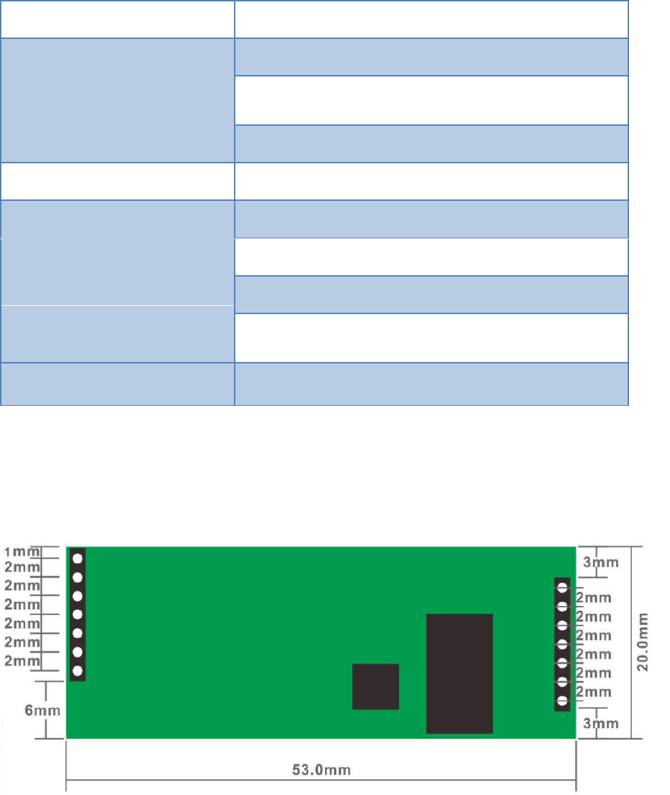
WPA-PSK/WPA2-PSK, WPA/WPA2
Network
WEB
Configuration
management
software
file
State indicator
Environmental
Working
Storage
Storage
standard
humidity:
humidity:
temperature:
Other performance
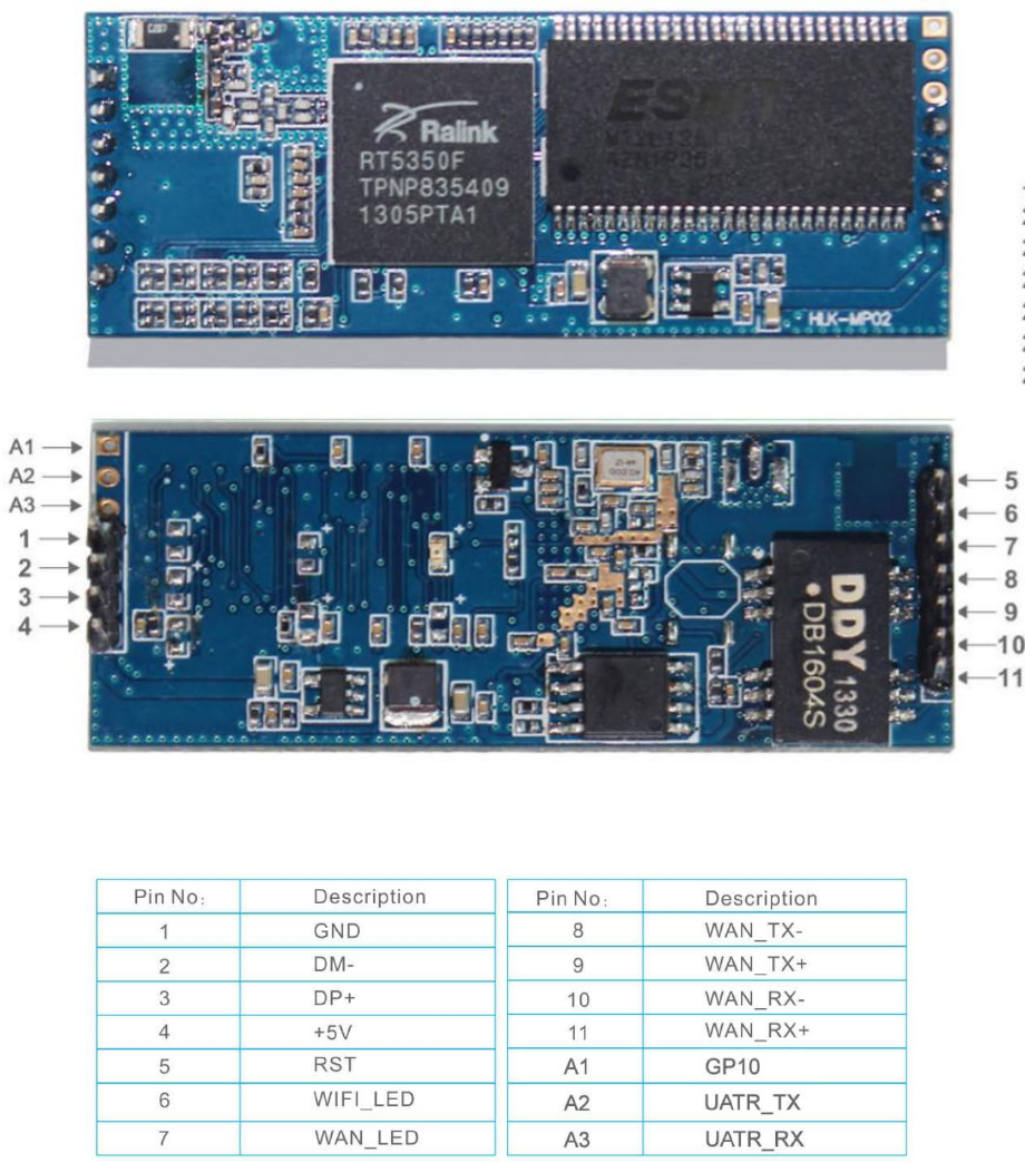
3. Mechanical size
Module size diagram
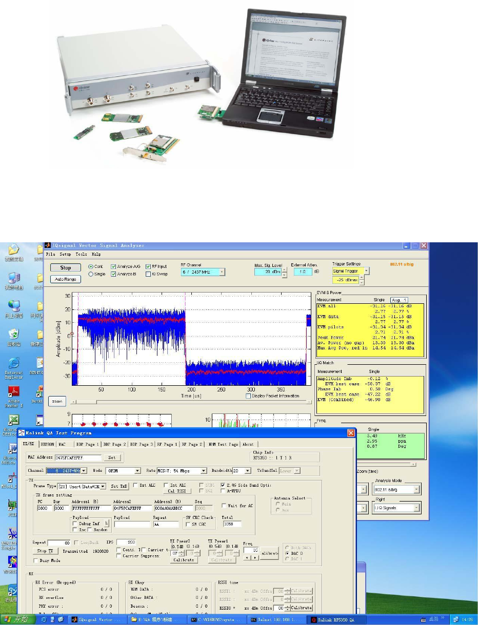
4. Definition of physical and pin
TOP and BTTOM physical drawings
Pin definition list
5. RF performance test
The performance test of RF is mainly done by the professional wireless comprehensive testing
instrument IQ-VIEW, which is tested by LITEPOINT WIFI.
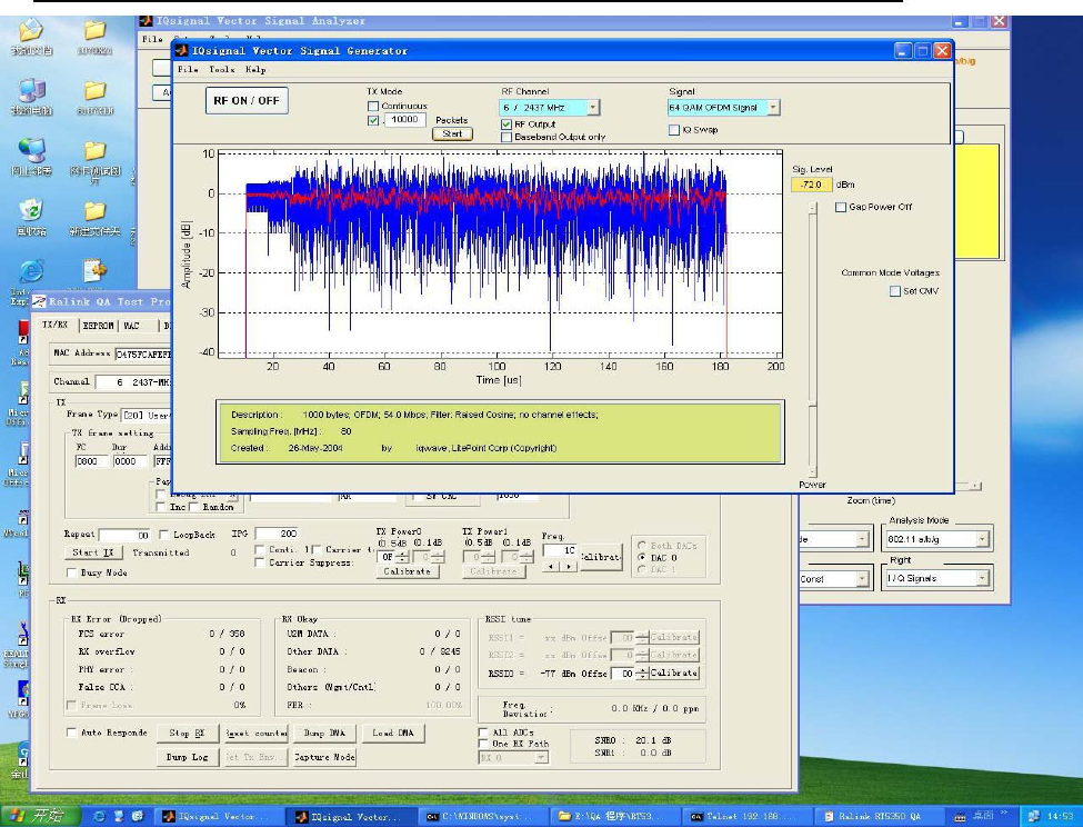
As shown in Figure 2, the average output power of the EVM is still up to the -31.16dB.
13.3dBm. Frequency error: 2.95ppm, far below the maximum limit specified by IEEE (+ 20ppm). As shown
in Figure 1, the reception sensitivity can also be reached to -72dBm @54Mbps.
FCC Warning
This device complies with Part 15 of the FCC Rules. Operation is subject to the following two conditions:
(1) This device may not cause harmful interference, and (2) this device must accept any interference received,
including interference that may cause undesired operation.
NOTE 1: This equipment has been tested and found to comply with the limits for a Class B digital device,
pursuant to part 15 of the FCC Rules. These limits are designed to provide reasonable protection against harmful
interference in a residential installation. This equipment generates, uses and can radiate radio frequency energy
and, if not installed and used in accordance with the instructions, may cause harmful interference to radio
communications. However, there is no guarantee that interference will not occur in a particular installation. If this
equipment does cause harmful interference to radio or television reception, which can be determined by turning
the equipment off and on, the user is encouraged to try to correct the interference by one or more of the following
measures:
- Reorient or relocate the receiving antenna.
- Increase the separation between the equipment and receiver.
-Connect the equipment into an outlet on a circuit different from that to which the receiver is connected.
-Consult the dealer or an experienced radio/TV technician for help.
NOTE 2: Any changes or modifications to this unit not expressly approved by the party responsible for
compliance could void the user's authority to operate the equipment.
Please notice that if the FCC identification number is not visible when the module is installed inside another
device, then the outside of the device into which the module is installed must also display a label referring to the
enclosed module. This exterior label can use wording such as the following: “Contains FCC ID:
2AD56HLK-MP02” any similar wording that expresses the same meaning may be used.
This equipment complies with FCC radiation exposure limits set forth for an uncontrolled environment. This
equipment should be installed and operated with a minimum distance of 20cm between the radiator & your body.
This transmitter must not be co-located or operating in conjunction with any other antenna or transmitter.
The module is limited to OEM installation ONLY.
The OEM integrator is responsible for ensuring that the end-user has no manual instruction to remove or install
module.
The module is limited to installation in mobile application;
A separate approval is required for all other operating configurations, including portable configurations with
respect to Part 2.1093 and difference antenna configurations.
There is requirement that the grantee provide guidance to the host manufacturer for compliance with Part 15B
requirements.