Hi Link Electronic HLK-RM08K WIFI Module User Manual 15 HLK RM08K UserMan r1
ShenZhen HaiLingKe Electronic co.,Ltd. WIFI Module 15 HLK RM08K UserMan r1
15_HLK-RM08K UserMan,r1
www.hlktech.net Email :sunny@hlktech.cn skype:hlktech
1
HLK-RM08K User Manual
ETHERNET
WIFI
Full Function Serial Network/Wireless Module
Contact:Sunny Shen Email :sunny@hlktech.cn Phone:86-15817488770
Skype:hlktech TEL
86-755-23152658-821
QQ:2859395931
Add: 3F,5# Building,Minxing Industrial Park,MinKang Rd
Minzhi,Longhua District,ShenZhen,China,518131

www.hlktech.net Email :sunny@hlktech.cn skype:hlktech
2
1.BRIEF INTRODUCTION .......................................................................................3
2 HARDWARE EXPLANATION
2.1 MECHANICAL DIMENSIONS ...................................
2.2 PINS DEFINITION ...................................................................................4,5,6
2.3 TYPICAL REFERENCE DESIGN .................................................................7
2.3.1 UART TO ETHERNET ........................................................................7
2.3.2 UART TO WIFI(AP OR STA)........................................................ 7
2.3.3 GATEWAY MODE OR REPEATER MODE.......................................7
3 TECHNICAL SPECIFICATION ............................................................................8
4 DETAILED FUNCTIONS ....................................................................................... 9
4.1 UART MODE ..................................................................................................9
4.1.1UART TO ETHERNET .........................................................................9
4.1.2 UART TO WIFI STA.......................................................................... 10
4.1.3 UART TO WIFI AP ............................................................................ 10
4.2 NETWORK MODE.......................................................................................10
4.2.1 GATAWAY MODE(DEFAULT MODE).........................................1
4.2.2 REPEATER MODE.............................................................................. 1
5 VERSION UPDATE INSTRUCTIONS................................................................ 12
................................ 3
Link Electronic Co.,Ltd
www.hlktech.net Email :sunny@hlktech.cn skype:hlktech
3
1. BRIEF INTRODUCTION
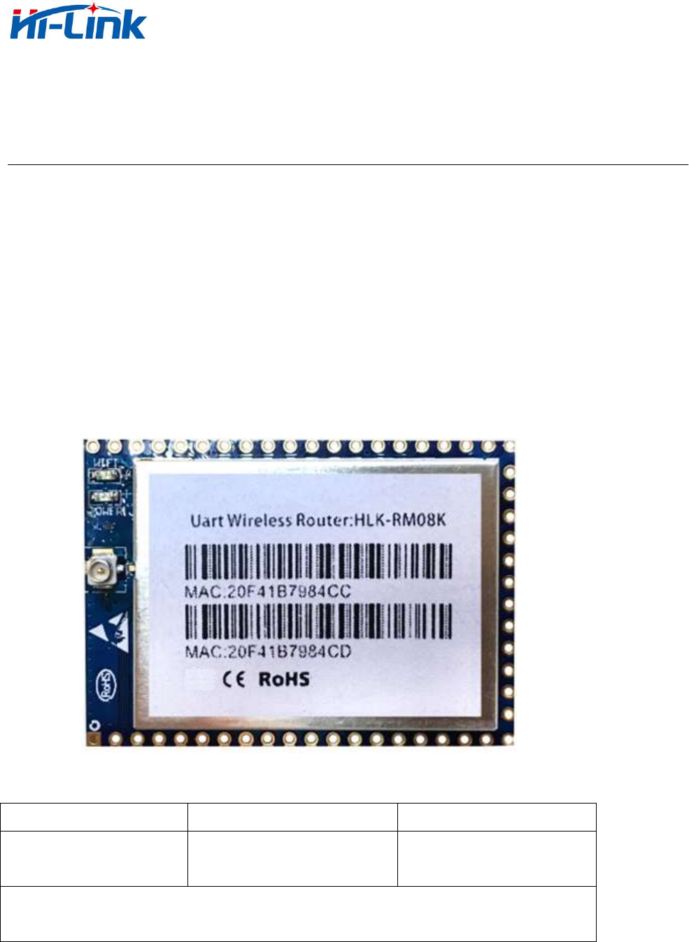
HLK-RM08K is a new low-cost embedded UART-ETH-WIFI module (serial
port - Ethernet - Wireless network) developed by Shenzhen Hi-Link (HK) co., Ltd.
The product is a low power consumption WIFI module,supports EEE802.11b/g/n wir
eless protocol with small size and smart use,ully transparent transmission UART module, b
uilt-in TCP / IP protocol stack, enabling users short development cycle. It just needs host
computer,WEB browser or APP to set up parameters, making the connection between UA
RT and network.
HLK-RM08K has stable performance and flexible use, meeting kinds of
requirements of users. and strong technical supports could be provided. Also, it could
be customized,such as WEB interface ,mobile phone app and so on.
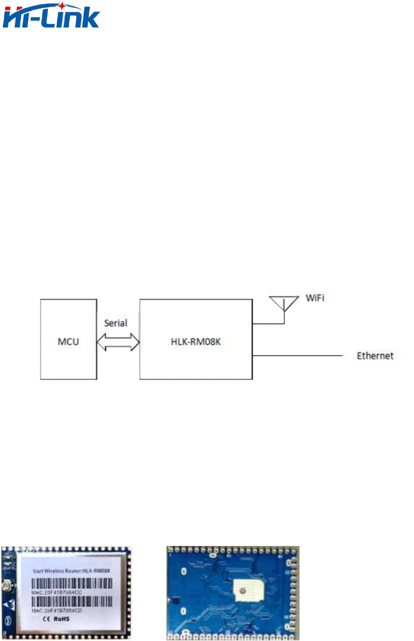
Diagram 1. Function structure
2. HARDWARE EXPLANATION
2.1 Meachanical Dimentsions
Top view Bottom view
Note:pitch of holes 2.0mm, pitch of holes 0.7mm.
Dimensions:40mm(length)X 29mm(width ) X 2.9mm(height)

www.hlktech.net Email :sunny@hlktech.cn skype:hlktech
4
2.2 Pin Definitions
No. FUNCTION DIRECTION DESCRIPTION
1 CTS1/G0 I/O CTS1
2 WDG O Watchdog
3 CTS0/G1 I/O CTS0
4 RTS0/G2 I/O RTS0
5 RES0 - (Reserved)
6 RES1 - (Reserved)
7 RES2 - (Reserved)
8 GND Power GND
9 WLED_N O WiFi LED(activate low)
10 VDD_O Power Out 3.3v OUTUP
11 EL4/G3 I/O ETH 4 LED
12 RES3 - (Reserved)
13 RES4 - (Reserved)
14 RES5 - (Reserved)
15 RES6 - (Reserved)
16 ES0 I ES0
17 TXN4/G4 A TXN4
18 TXP4/G5 A TXP4
19 RXP0 A RXP0
20 RXN0 A RXN0
21 TXP1/G6 A TXP1
22 TXN1/G7 A TXN1
23 RXP1/G8 A RXP1
24 RXN1/G9 A RXN1
25 RXP2/G10 A RXP2
26 RXN2/G11 A RXN2
27 TXP2/G12 A TXP2
28 TXN2/G13 A TXN2
29 TXP3/G14 A TXP3
30 TXN3/G15 A TXN3
31 RXP3/G16 A RXP3

www.hlktech.net Email :sunny@hlktech.cn skype:hlktech
5
32 RXN3/G17 A RXN3
33 RXP4/G18 A RXP4
34 RXN4/G19 A RXN4
35 TXN0 A TXN0
36 TXP0 A TXP0
37 INT O INTERRUPT (Reserved)
38 RX0 I RX0
39 TX0 O TX0
40 RX1/PWM0 I/O RX1
41 ELED0 O ETH 0 LED(activate low)
42 RST I Reset
43 ES1 I ES1
44 TX1/PWM1 I/O TX1
45 G20 I/O GPIO20 (Reserved)
46 VCC POWER 5V INPUT
47 EL1/G21 I/O ETH 1 LED
48 EL2/G22 I/O ETH 2 LED
49 EL3/G23 I/O ETH 3 LED
50 GND Power GND
51 RES7 - (Reserved)
52 RTS1/G24 I/O RTS1
Note: reserved pin is currently not used,please hang!
ES0 Function Introductions :
1. After System boot, ES0 keep the lower level time 0.05s<t<6s, Serial 0 exit
transparent transmission.
2. After System boot, ES0 keep the lower level time 6s<t<12s, client settings
reset.
3. On electic ES0 is a lower level, the lower level time 6s<t<12s, client settin
gs reset.
ES1 Function Introductions :
1. After System boot, ES1 keep the lower level time 0.05s<t<6s, Serial 1 exit
transparent transmission.
2. After System boot, ES1 keep thelower level time 6s<t<12s,factory reset.
www.hlktech.net Email :sunny@hlktech.cn skype:hlktech
6
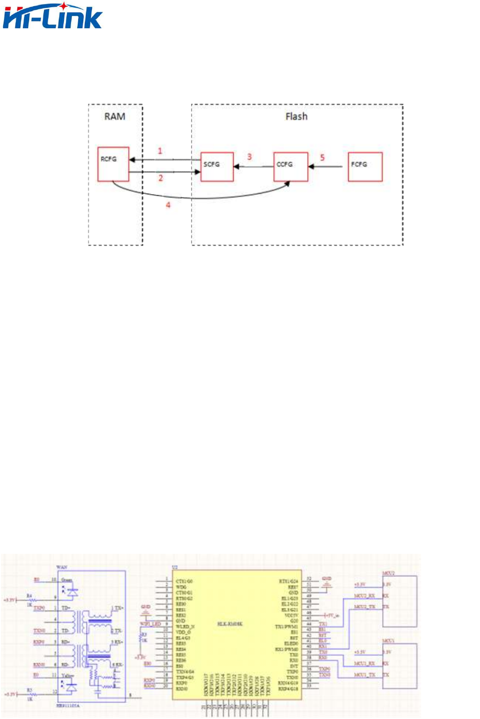
Parameter storage :
RCFG:The parameters in the memory.
SCFG:General parameters.
CCFG:Save To C Instructions to save parameters.
FCFG:Factory factory Settings. Users can't modify.
1. Power on,module read SCFG to RCFG from flash.
2. Save instructions RCFG to SCFG.
3. Restore settings,copy CCFG to SCFG.
4. Save To C Save instructions RCFG to CCFG.
5. Factory resetting,copy FCFG to CCFG.
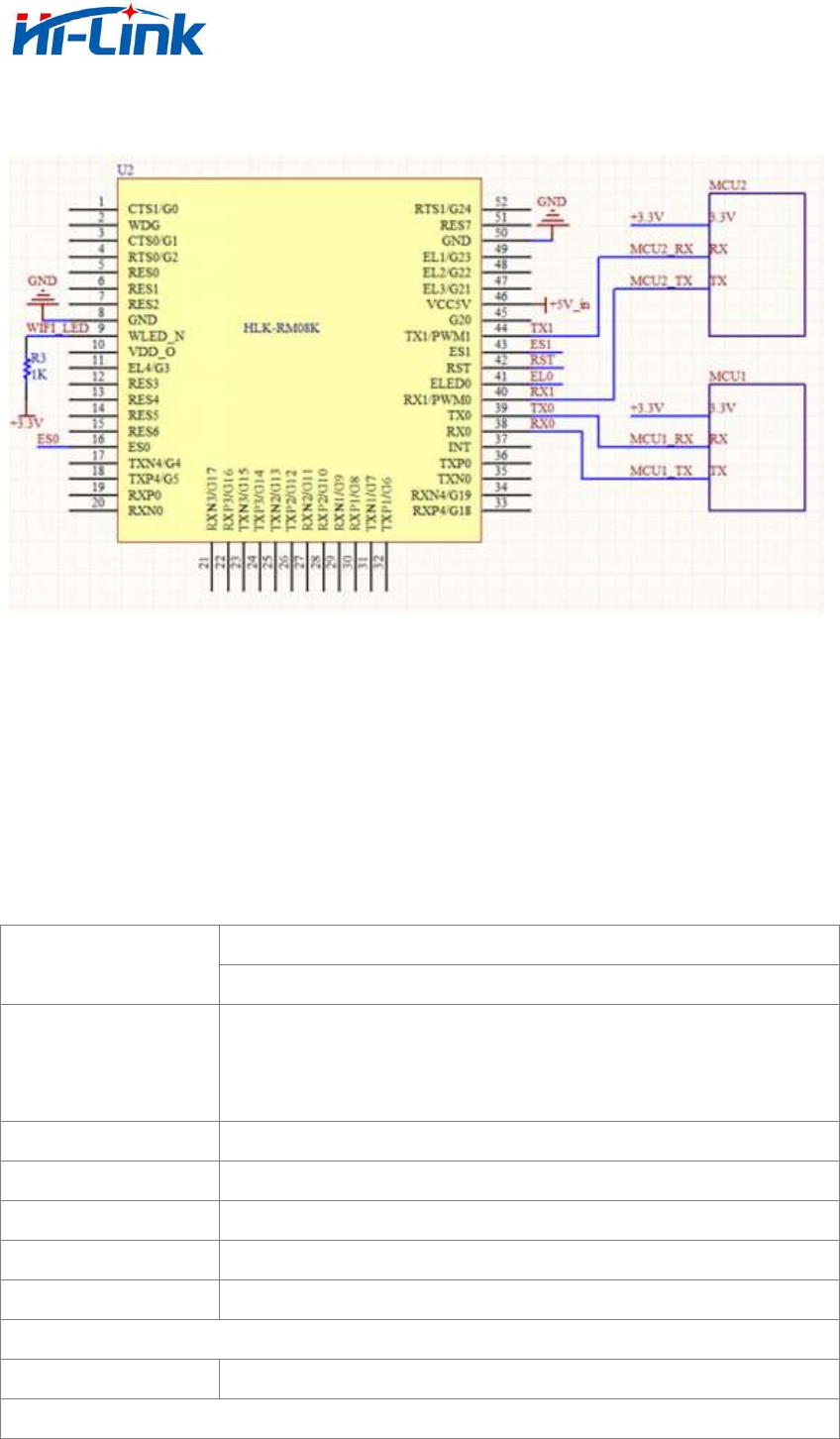
2.3 TYPICAL REFERENCE DESIGN
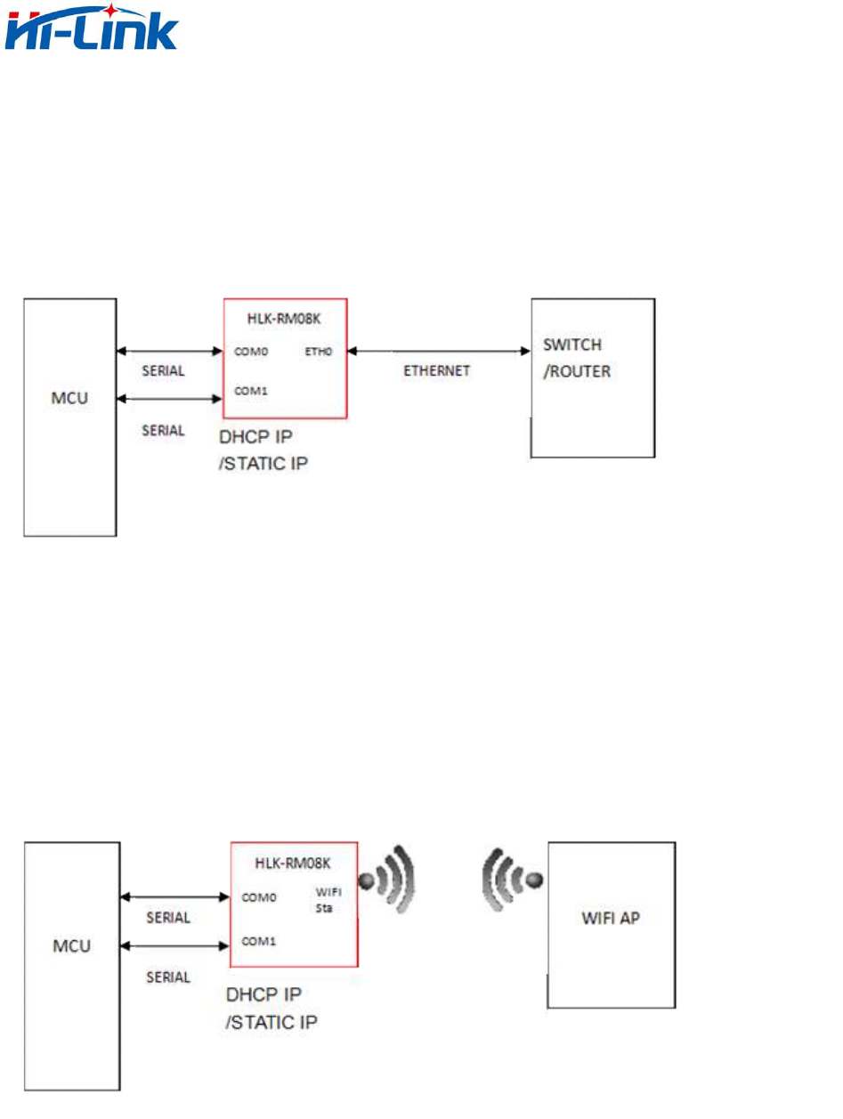
2.3.1 UART TO ETHERNET
www.hlktech.net Email :sunny@hlktech.cn skype:hlktech
7
2.3.2 USRT TO WIFI(AP OR STA)
2.3.3 GATAWAY MODE OR REPEATER MODE
Please refer to diagram of test board.
3. TECHNICAL SPECIFICATION
Wireless standard : IEEE 802.11n、IEEE 802.11g、IEEE 802.11b
Network standard
Wired standard : IEEE 802.3、IEEE 802.3u
Wireless transmission rate
11n:Max150Mbps
11g:Max54Mbps
11b:Max11Mbps
Channels 1-11
frequency range 2.4-2.4835G
Transmit power 8 -18DBM
Receive Sensitivity -70DB
Connector 1WAN\4LAN\2UART
Antenna
Antenna type FPCB antenna (IPEX)
Function parameter

www.hlktech.net Email :sunny@hlktech.cn skype:hlktech
8
WIFI working mode STA/AP/Wireless Router
Repeater mode Support wireless bridge
Wireless MAC address filtering
Wireless switch security function
64/128/152bit WEP encryption
Wireless security
WPA-PSK/WPA2-PSK、WPA-TKIP/WPA2-TKIPsecurity mechanism
Web interface management
Configure file lead-in/out
Network management
WEB interface software upgrade
UART to network
Dual UART transparent transmission,two uart ports work individually
TCP socket connection Max connection number>20
UDP socket connection Max connection number>20
Serial baud rate 1200—2500000bps (2500000/n 1<=n<=65535)
Power consumption
MODE P C( m W ) NOTE
UART TO WIFI 110mA x 5V AP or STA(all the net ports closed)
UART TO ETH 70mA x 5V works only in WAN
Gateway mode(default mode) 160mA x 5V
Wifi both WIFI and five NET
ports work
Repeater mode(bridge mode) 160mA x 5V
Wifi both WIFI and five NET
ports work
Other parameters
Status light Status indication
Working temperature:-20-55℃
Working humidity:10%-90%RH(NONCONDENSING)
Storage temperature:-40-80℃
Environmental standards
Storage Humidity:5%-90%RH(NONCONDENSING)
Other functions Optional frequency bandwidth:20MHz\40MHz,AUTO
www.hlktech.net Email :sunny@hlktech.cn skype:hlktech
9
4. DETAILED FUNCTIONS
4.1 UART MODE
4.1.1 UART TO ETHERNET
Diagram 2. UART to ETH
In this mode,ETH0(WAN port)enabled. Closed.
Ethernet could configure as dynamic IP ( DHCP ) ,also could configure as static
IP(static).
4.1.2 UART TO WIFI STA
Diagram 3. UART to WIFI STA
In this mode, WIFI enabled,working in STA mode, Ethernet closed.
WIFI STA could configure as dynamic IP (DHCP), also configure as static
IP(STATIC).
www.hlktech.net Email :sunny@hlktech.cn skype:hlktech
10
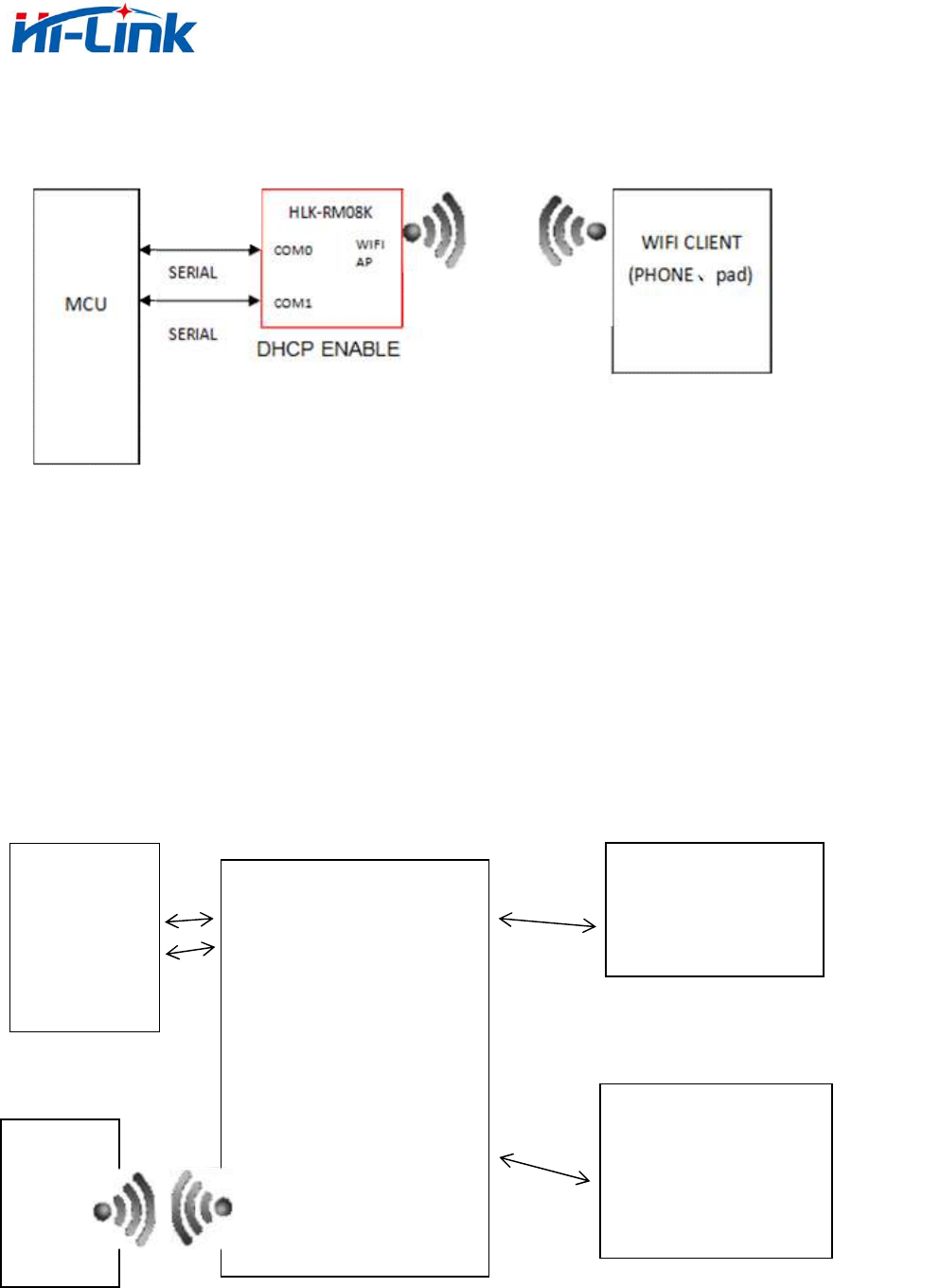
4.1.3 UART TO WIFI AP
Diagram 4. UART TO WIFI AP
In this mode, WIFI enabled, working in AP mode, Ethernet closed.
In this mode, WIFI device could connect module, as one working in WIFI local area
net.
4.2 NETWORK MODE
4.2.1 Gateway mode (defaul mode)
MCU
COM0
HLK-RM08K
COM0
WAN
COM1
ROUTER
LAN
PC/SWITCH
WIFI
CLIENT
(PHONE,
PAD)
WIF
www.hlktech.net Email :sunny@hlktech.cn skype:hlktech
11
Diagram 5. Default mode
In this mode, module connects router by WAN, Module’s WAN IP can be set to
automatically obtain IP ( static DHCP),
Module’s 4 LAN port could connect PC directly, PC can directly obtain IP addresses
from module;
Module acts as AP now, clients could connect its WIFI directly.
4.2.2 PEPEATAR MODE
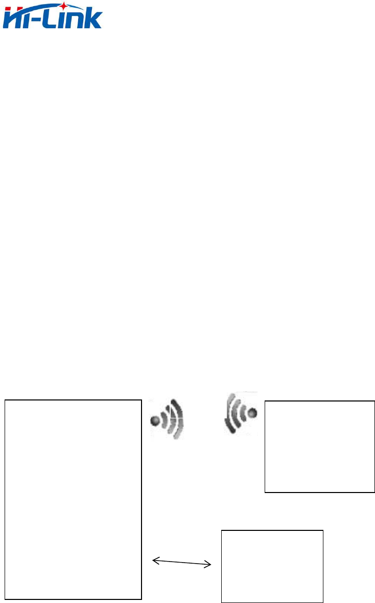
Diagram 6. Repeater mode
In this mode, module connects AP with WIFI and emission WIFI itself, mobile phone
and other clients could connect its WIFI directly. Meanwhile, five ETH ports are LAN,
PC and other devices could connect module with Ethernet cable.
Note : The client(such as mobile phone,PC)’IP address is assigned by AP once
connected module,
PC/SWITCH
HLK-RM08K
WiFi
client
ETH PORT
WIFI AP
WIFI

www.hlktech.net Email :sunny@hlktech.cn skype:hlktech
12
Module is functioned as PBX.
5.VERSION UPDATE INSTRUCTIONS
VERSION NO. NOTE MODIFIER TIME
V1.0 USER MANUAL KAVIN 2016.01.13
FCC Warning
This device complies with Part 15 of the FCC Rules. Operation is subject to the following two conditions:
(1) This device may not cause harmful interference, and (2) this device must accept any interference received,
including interference that may cause undesired operation.
NOTE 1: Any changes or modifications to this unit not expressly approved by the party responsible for
compliance could void the user's authority to operate the equipment.
FCC Radiation Exposure Statement:
This equipment complies with FCC radiation exposure limits set forth for an uncontrolled environment. End users
must follow the specific operating instructions for satisfying RF exposure compliance.
Note 1: This module certified that complies with RF exposure requirement under mobile or fixed condition, this
module is to be installed only in mobile or fixed applications.
A mobile device is defined as a transmitting device designed to be used in other than fixed locations and to
generally be used in such a way that a separation distance of at least 20 centimeters is normally maintained
between the transmitter's radiating structure(s) and the body of the user or nearby persons. Transmitting devices
designed to be used by consumers or workers that can be easily re-located, such as wireless devices associated
with a personal computer, are considered to be mobile devices if they meet the 20 centimeter separation
requirement.
A fixed device is defined as a device is physically secured at one location and is not able to be easily moved to
another location.
Note 2: Any modifications made to the module will void the Grant of Certification, this module is limited to OEM
installation only and must not be sold to end-users, end-user has no manual instructions to remove or install the
device, only software or operating procedure shall be placed in the end-user operating manual of final products.
Note 3: Additional testing and certification may be necessary when multiple modules are used.
Note 4: To ensure compliance with all non-transmitter functions the host manufacturer is responsible for ensuring
compliance with the module(s) installed and fully operational. For example, if a host was previously authorized as
an unintentional radiator under the Declaration of Conformity procedure without a transmitter certified module
and a module is added, the host manufacturer is responsible for ensuring that the after the module is installed and
operational the host continues to be compliant with the Part 15B unintentional radiator requirements. Since this
may depend on the details of how the module is integrated with the host, Shenzhen HaiLingKe Electronic co., Ltd.
shall provide guidance to the host manufacturer for compliance with the Part 15B requirements.
Note 5: FCC ID label on the final system must be labeled with “Contains FCC ID: 2AD56HLK-RM08K” or
“Contains transmitter module FCC ID: 2AD56HLK-RM08K”.
The OEM integrator is still responsible for the FCC compliance requirement of the end product, which integrates
this module.