Hi Target Surveying Instrument ZHDV30PRO GNSS RTK User Manual
Hi-Target Surveying Instrument Co., Ltd GNSS RTK
Users Manual

Handbook revision situation
Warning: Changes or modifications to this unit not expressly approved
by the party responsible for compliance could void the user’s authority to
operate the equipment.
NOTE: This equipment has been tested and found to comply with the
limits for a Class B digital device, pursuant to Part 15 of the FCC Rules.
These limits are designed to provide reasonable protection against
harmful interference in a residential installation. This equipment
generates, uses and can radiate radio frequency energy and, if not
installed and used in accordance with the instructions, may cause
harmful interference to radio communications.
However, there is no guarantee that interference will not occur in a
particular installation. If this equipment does cause harmful interference
to radio or television reception, which can be determined by turning the
equipment off and on, the user is encouraged to try to correct the
interference by one or more of the following measures:
Reorient or relocate the receiving antenna.
Increase the separation between the equipment and receiver.
Connect the equipment into an outlet on a circuit different from that to
which the receiver is connected.
Consult the dealer or an experienced radio/TV technician for help.
Shielded cables must be used with this unit to ensure compliance with
the Class B FCC limits.

Static and Data Transmission
Receiver Introduction
Chapter Introduction
■ Receiver Appearance
■ Control Panel
■ Upper Cover
■ Below Cover
■ Communication Module
■ Battery
■ Environmental Requirement
■ Electric Interference
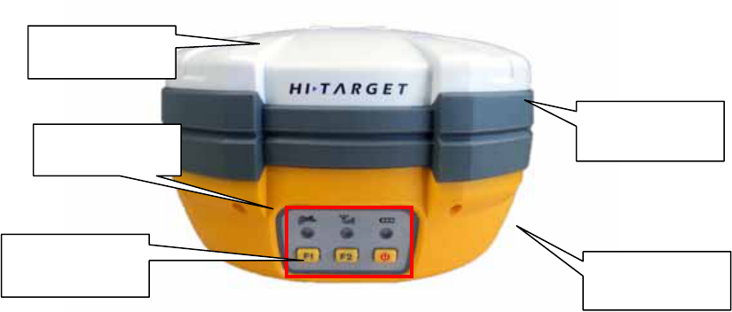
Receiver Appearance
Receiver Appearance mainly including 4 parts: upper cover,
below cover,
guard collar and control panel, as Figure 2-1
Figure 2-1 Receiver Appearance
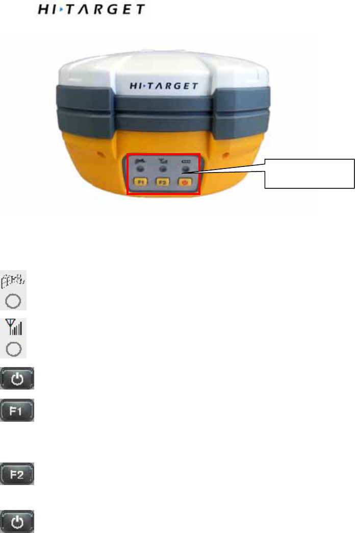
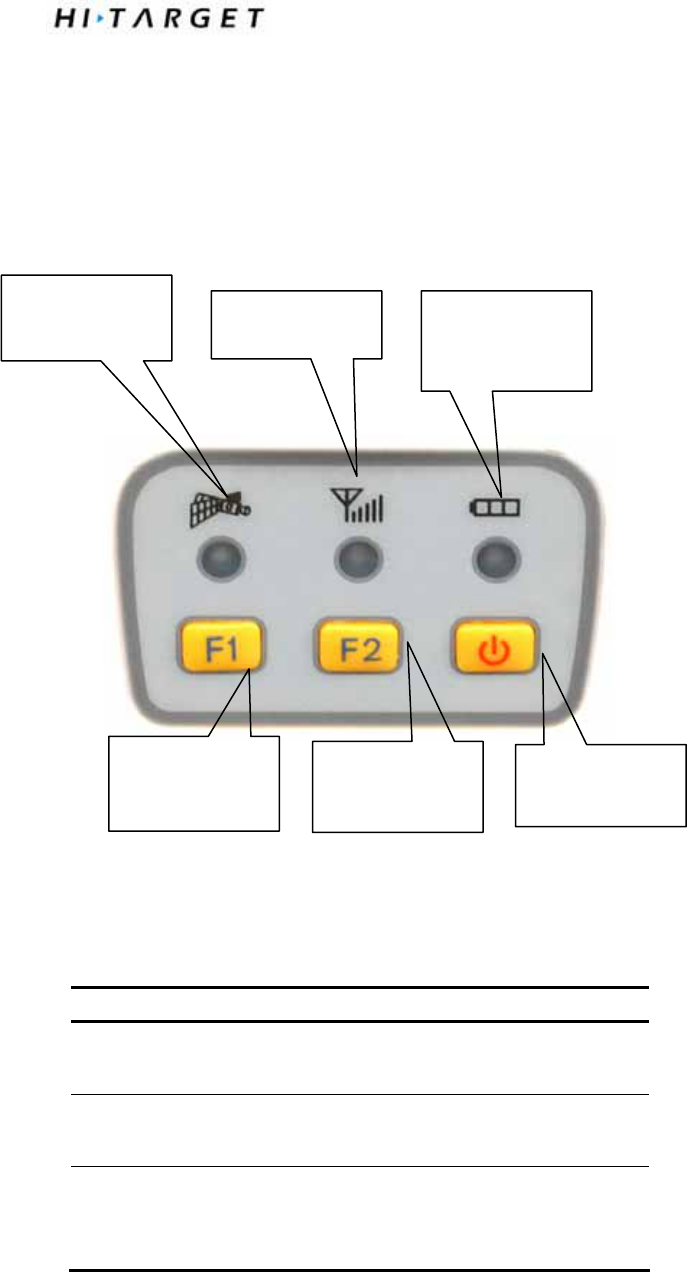
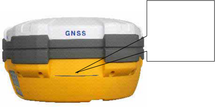
Control Panel
Figure 2-2, in the middle of red frame of V30 receiver is control panel.
And the control panel contains the F1 key (function key 1), F2 key (function
key 2) and the power button, 3 indicator leds which are respectively satellite
led, the status led (dual-color led ), the power led (dual-color led). The simple
three buttons include all the features setting of the v30 receiver.
Upper cover
Screw
Control panel
Guard collar
Below Cover
Static and Data Transmission
Figure 2-2 control panel
satellite led(green led)
status led(red-green dual-color led)
power led(red-green dual-color led)
Function Key: settings of working mode, UHF radio transmitting power,
satellite elevation angle, automatically base setting,self inspection,reset receiver
reset receiver and so on.
Function Key: settings of data link, UHF radio channels, collection interval,
back to original setting,stop and go,upload static data.
ON-OFF power key: Status Enquiry ,setting confirmation, automatically base
setting,switch on/off voice assistant and so on.
Control panel
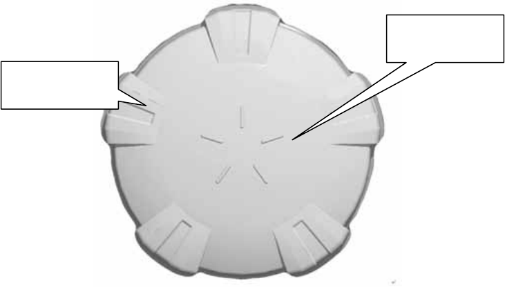
Upper Cover
Figure 2-3
Raised Point: anti-wear point to avoid instrument being scratched
Raised Plate: 5 raised plates can avoid wear-out and falling
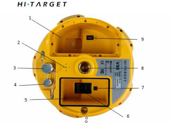
Below Cover
As figure 2-4, below cover of V30pro includes communication module slot,
battery groove, five-pin port, eight-pin port, speaker and so on.
Raised Plate
Raised Point
Static and Data Transmission
1-Radio module 2-Speaker 3-Eight-pin port and cover 4-Five-pin port and cover
5-Battery groove 6-SLC Power supply Block 7-Joint nut 8-Communication Module
Connector
Figure 2-4 Below cover
◊Radio Module Groove:to set radio module.
◊Radio Module Connector: connect radio module and
mainframe
◊ Battery Groove: install li-ion battery
◊SLC Power Supply Block: connect li-ion battery and mainframe
◊ Five-pin port: connect mainframe with external data link or with external power supply
◊Eight Core socket: connect V30pro receiver with computer, or controller for
data download and delete
◊ Protection Plug: anti-dust and waterproof for socket
◊ Joint Nut: fix instrument with tribrach and centering pole.
◊Speaker: voice broadcast for real-time operation and status.
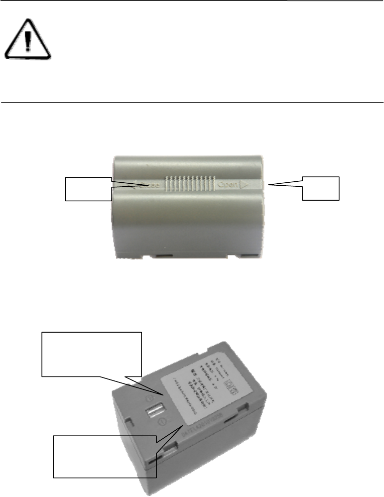
Battery
As figure 2-7, the appearance of 5000mAhli-ion Battery
Figure 2-5 Battery Front
Figure 2-6 Battery Back
Note: 1. If it is not necessary to use five-pin port, eight-pin port and
differential antenna port, please affix rubber plugs , to prevent it from
water and dust.
2. when speaker is filled with water, maybe speaker becomes
silent or hoarse. But it will be back to normal after drying .
Close Open
Battery positive
pole
Battery negative
pole

Static and Data Transmission
Environmental Requirement
Even though V30 receiver uses waterproof materials, maintaining in a dry
environment is still helpful. In order to improve the stability, and duration of the
receiver, please avoid exposing the receiver in extreme environments, such
as:
Moist
temperature higher than 65 degrees
temperature lower than -40 degrees
corrosive liquid or gas
Electrical Interference
Do not place GNSS receiver around a strong power interference signal
source, such as:
Oil Road ( spark plug )
television and computer monitor
generator
electric motor
DC-AC power conversion equipment
Fluorescent Light
Power switcher
C H A P T E R 3
General Operations
Introduction of this chapter:
■control panel
■ Button Functions
■ Turn On/Off Receiver
■ Static Data Storage
■ RTK Data Storage
■ Receiver self inspection
■upload static data file
■Set receiver password
■Voice assistant
■Reset receiver
■ Back to Original Settings
■ Format Receiver
■ Power Supply System
■Radio Module
■ Firmware
Static and Data Transmission
Control Panel
Most of the operations of V30pro receiver can be done by the three buttons
on the mainframe panel.
Buttons on the panel:
Figure3-1 Mainframe Panel
Explanations of buttons operations and leds hints as below:
Operations Explanation
表3.1 按键操作时间说明
operation introduction
Single click
button
Press a button within 1 second
Double click
button
Press a button within 1 second
Long pressing
button
Pressing button for 3 to 6 seconds,until you
hear the sound of "dingdong"
Satellite Led Status Led Power on/off
Led
Function button
F1
Function button
F1
Power on/off

Super long
pressing
Pressing button more than 6 seconds,until you
heard the sound of "dingdong".
Long press
F1+power
button to turn
on receiver
Hold F1+power button,until you hear the sound
of "dingdong"
Slow flash of
led
Flashing interval more than 0.5 second
Fast flash of
led
Flashing interval less than 0.3 second
Button functions
Table3.2 Button function introduction
function Button
operatio
ns
introduction
Working mode Double
click F1
Than single click F1 to choose the receiver work
mode
between “base”, “rover”, “static”
Data link Double
click F2
Than single click F2 to choose the data link between
“External”
power Long
press F1
Then single click F1 to set the transmit power to be
high,
UHF
mode
Chan
nel
Long
press F2
Than single click F1 to choose channel by minus 1;
or you can long pressing F1 to choose channel by
minus 10;or single click F2 to choose channel by
plus 1; or you can long pressing F2 to choose
channel by plus 10
Static Eleva
tion
angle
lLong
press F1
Single press F1 to set elevation angle to be 5
degrees,10 degrees, or 15 degrees

Static and Data Transmission
Colle
ction
interv
al
Long
press F2
Single press F2 to set collection interval to be
1s,5s,10s,15s
Stop
and
go
Double
click F2
Double click F2 to start or stop record(only when
you start the "stop and go ",this operation works
Confirm setting
Single
press
power
button
Than the receiver will speak out its current work
mode,
data link, radio transmit power, channel; meanwhile
the
power led will flash to hints its power status
Auto-set base
F1+Pow
er
button to
turn on
receiver
Press F1 while than press power button at th same
time
to turn on the receiver until hearing “Dingdong”.
Then
the receiver speak out its current status.
Single press F1 to self inspection
Reset receiver
and self
inspection
Supper
long
press F1 Single press F2 to reset the motherboard
Single pressing F1 to upload static file
Upload static
file and come
back to original
settings
Supper
long
pressing
F2
Single pressing F2 to come back to original setting
Turn on Press
power
button
for 1s
In shutdown state,long press power button for 1s,
relax the button after all the LED flash
po
we
rbu
tto
n
Turn off Long
press
power
button
In turning on state,long press power button for3s,
then it will shutdown

Check
currect
work
status
Single
pressing
power
button
In non-settings status
,inquiry the current working mode,data link and
radio channel,voice hints,at the same time the
power led flashing times hints the power
status
Confirm
setting
Single
pressing
power
button
In setting status , then confirm
Open or
close
voice
assistant
Double
pressing
power
button
Double pressing power button will open or close
voice assistant
Voice assistant After you have opened the voice assistant,single
press F1 or F2 you will get voice assist
Other button operation Invalid operation:when you do invalid operation,the
machine will come up with an alarm of “du”,if you
do 3 errors ,you will hear 3”du” ,with the voice
tip:invalid operation,if you need voice assist ,please
double click power power button
Start and stop the receiver
Table 3.3 LED in power on/off status
Power
on
Press the
power
button for
1s
All the LED
will flash
With the shutdown music,it will prompt
you the working mode and data link last
time
Power
off
Long
pressing
power
button 3s
All the LED go
out
With shutdown music
Static and Data Transmission
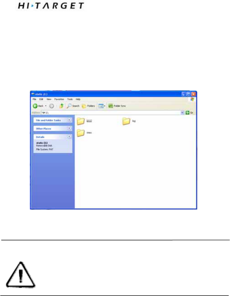
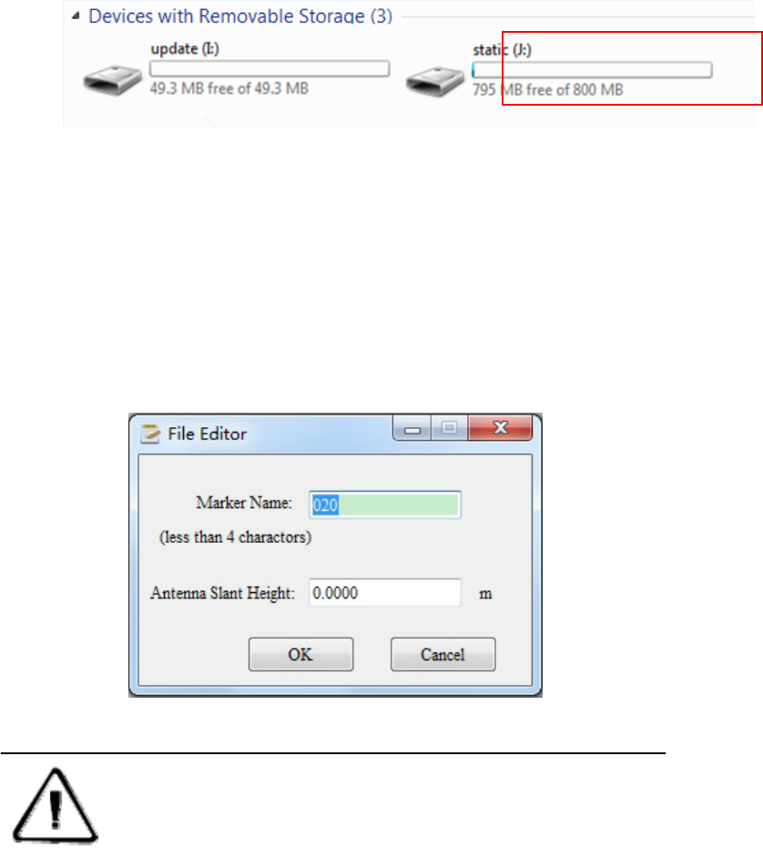
Static data storage
Acquisition of GNSS static data will be stored in iRTK receiver’s internal 1 G
storage- "static" plate , avaliable storage space is 800 M, there are three folders:
log, gnss and rinex, log folder store log information, the format of GNSS folder
data is *. GNS,the format of rinex folder stored data is standard RINEX format. You
can connect the computer with Y data cable or USB , copy the static data to your
computer.
RTK data storage
IHand 28/iHand 28G hand book can connect HI-TARGET iRTK receiver through the
network, bluetooth or cable connection , when you finished the setting and start
working , the collected RTK data will be stored in the hand book storage card, you
can download RTK data to your computer by data cable.
Note:when the storage space of the receiver is less than 1M,data
lamp quickly flash,and stop to record data,the existed data file will
not be covered.

If you want to know more about the information of hand book, please read iHand
28/iHand 28G hand book manual.
Self inspection
Super long pressing the F1, you will hear the voice broadcast "press F1 to self
inspection, press F2 reset motherboard, click F1 to start self inspection, after self
inspection,it will announce the current instrument working status and parameter.\
Upload static data file (only for deluxe edition, compass edition)
There are to methods to upload the latest static data file
Method one:
In static mode, super long pressing F2, the static data acquisition will stop, and
then click F1, voice prompt will tips you :”start upload static file to the server”, at
this time the signal red light flash. Upload data after the success of the speech to
be automatic hint "upload data success". After you upload data successfully,you
will hear the voice prompt “upload data successfully”.After you upload data
successfully ,the receiver will automatically start of a new round of static data
acquisition.
Method 2:
1. Double-click the F1 to stop recording and change the current work mode to base
or rover mode;
2. Super long press F2, single click the F1 ,you will hear voice prompt :start to
upload static file to the server, at this time the signal red light flash. After
uploading data successfully ,you will hear the voice prompt "upload data
successfully".
Static and Data Transmission
2 The data which receiver upload is a static data files (only support *. GNS format
data to upload).
3. When static data file is bigger than 3M, we do not suggest you to use network to
upload so as not to affect the running speed of server ,also affect your work
efficiency.
4. Before uploading ,if the receiver shutdown ,or the 3G card can not offer network
service normally ,all the files will be uploaded unsuccessfully and you can never
upload this file!
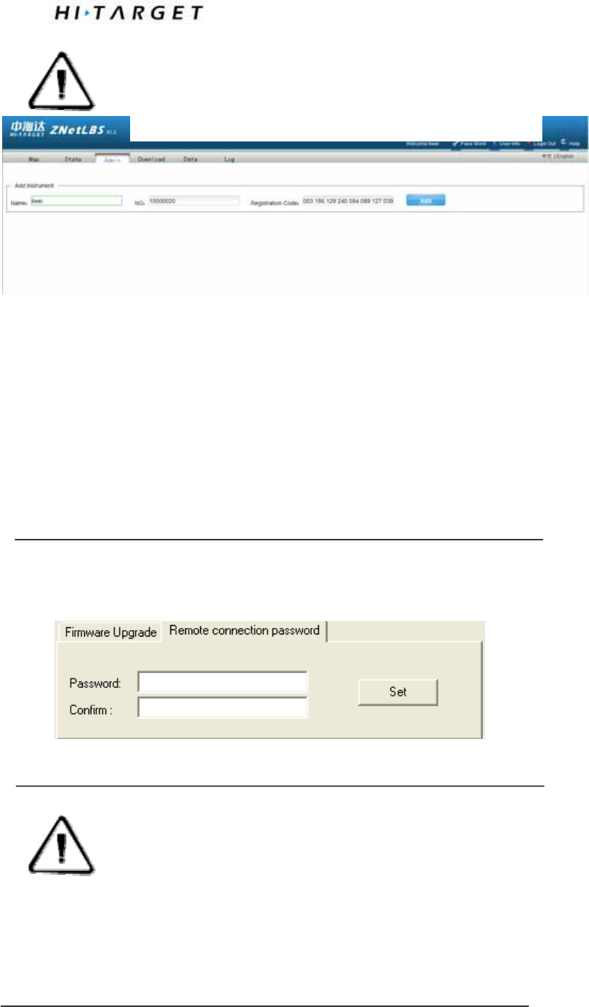
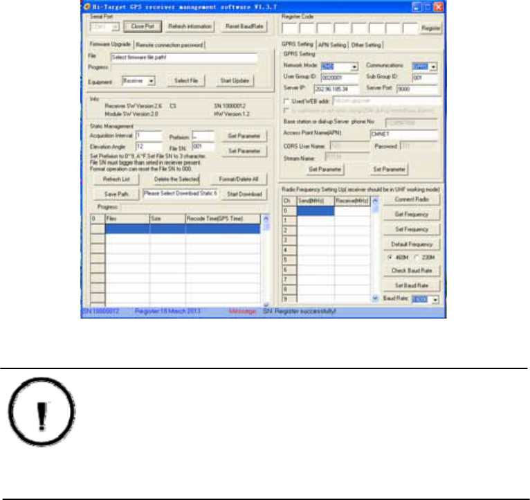
Set receiver password
Connect the PC with Y data cable, run the HI-TARGET serial receiver management
software,choose the right port and connect it,after connection,set remote
connection password and remember it.
Figure3-4
Note: 1. Before using this function,you need to insert the 3
G SIM card which is available to network , register on the
LBS server before uploading the data.
Note: 1. We suggest you immediately set the password
after you buy it,when you use the remote
connection ,remember your password to guard against
theft intelligently.
2. If you forgot the password, you can set it to original
state to get your password.
Voice assist
In any mode, double-click power key, it can open voice assist to help the user
accomplish your operation.
Reset receiver
Super long press the F1, single click the F1 to self inspection, single click F2 to
reset motherboard, it takes you 1 minutes to reset motherboard, after reset there
will be voice prompt.
Back to factory setting
Super long press F2, single click F2 to original parameter Settings, each module
will automatically diagnosis and recovery. Details please refer to appendix 4: iRTK
parameters.
Formatting receiver
When you want to format iRTK receiver, use Y data cable to connect with
computer , run the GPS receiver management software, choose a serial port and
open the serial port, when instrument get connection, the serial number will be
displayed in the bottom of the software interface, click "format/delete all" to
complete the receiver's formatting, all data are deleted, unable to recover.
Figure
Warning: Before formatting iRTK receiver , make sure that
useful data in the receiver have been copied to the computer,
once deleted or formated,it will never recover!

Static and Data Transmission
Power Supply System
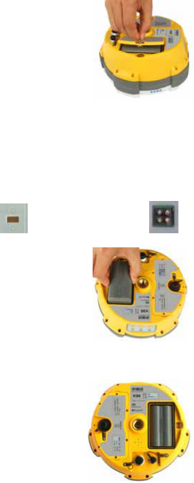
Assembly and Disassenbly of Battery Cover
Assembly:
1.Firstly put two teeth of the cover into the slots and press the cover.
Figure 3-6
2.Rotate the metal lock 90 degree anticlockwise and press the lock.
``
Figure 3-7
Disassembly:
1.Pull the lock up and rotate it 90 degree clockwise
Figure 3-8
2.Pull it to remove the battery cover
Figure 3-9
Install and Unistall Battery
Install:
1.Match one the battery with the on the battery groove
Figure 3-10
2.Insert battery towards “Close” side (see the red arrow) to install it
Figure 3-11
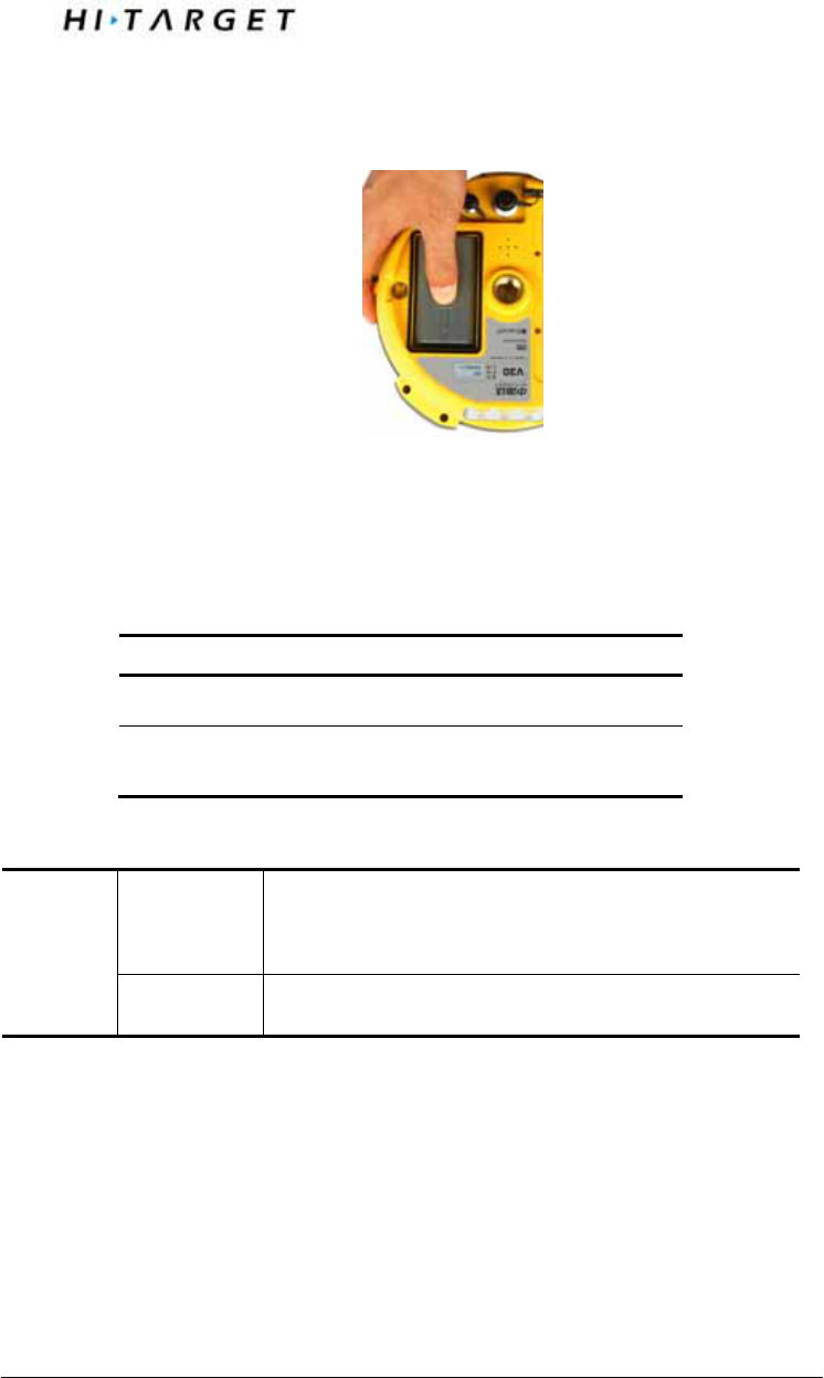
Static and Data Transmission
Uninstall:
Slide the battery towards to the “Open” side, and then pull out battery.
Figure 3-12
iRTK Receiver Battery Name and Model
Name Model
5000mAh lithium battery BL-5000
iRTK lithium battery
charger CL-4400
Power Supply Mode
Mode
1. lithium battery;
2. 8-pan port and 5-pin port on the mainframe
for external power supplier
Power
Supply
Range DC 6V~30V
iRTK receiver can get power by external supplier by 8-pin or 5-pin port on the
mainframe. When using the GSM or UHF communication mode, the external
power supply should be 6~36V and current should be more than 500mA.
When it is connected to both power suppliers(external and battery), receiver
will adopt the one with a higher voltage. To avoid any destroy to the receiver,
make sure that your engaged external power supplier should be the one
furnished by Hi-target.
Note :1.The endurance of li-ion battery will be decreased by
the decreasing temperature and increasing time of
charging and consuming. Normally a new BL-5000
battery can provide power for 14 hours under the static
mode, 9 hours under GSM rover mode and 2 watt UHF
base mode.
2.In order to prolong the life of battery, please charge
the drained battery in 8 hours.
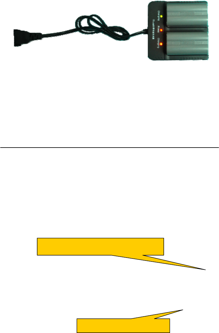
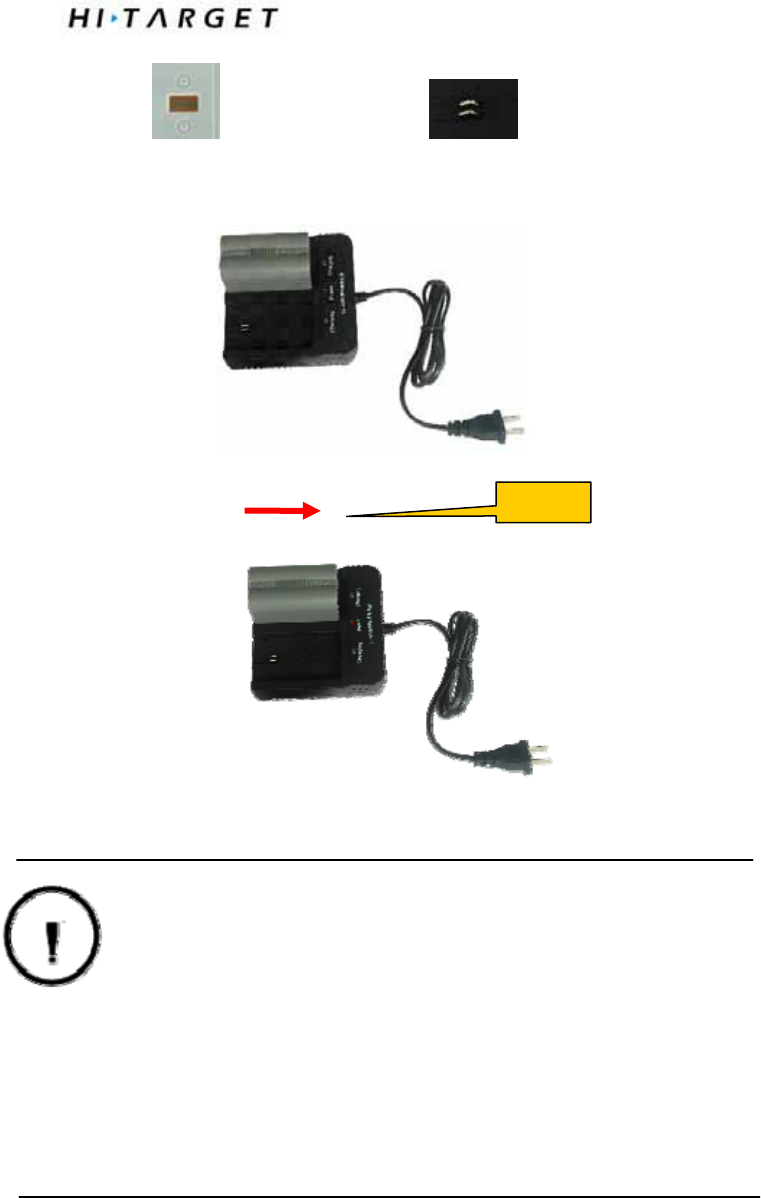
Charging battery
BL-5000 battery must be charged in specified CL-4400 charger of Hi-Target
for about 7.5 hours. The indicator led will be in red while charging and turn to
green when it is almost finished and then be fully charged after another 1~1.5
hours.
Figure 3-13
Charging Operations
Green led for almost finishing charging
Red led for charging now
Static and Data Transmission
1.Matching the side of battery with of the charger, put it as
the Figure 4-11 shows.
Figure 3-14
2.Slide battery towards “Close” side (as the above arrow direction) until
battery is locked
3.After connecting charger with power supply, the “Charging” led becomes
red.
Warning: 1. Battery can only be charged by charger furnished
by Hi-Target. Do not throw it into fire nor touch
with things that will lead to short circuit fault.
2.If battery is heating, leaking, deformed or smelly at
work, charge or being stored, stop and change
another one at once.
3.If the endurance is much shorter than it was before,
change another one.
Close
Hi-RTK Multifunction Controller
Software
Introduction:
Introduction
Connect Mainframe
iRTK Operation
Instrument Register
Static and Data Transmission
Introduction
In order to give user a quick start, this chatper simply introduce the basic
operation of Hi-RTK software including connecting the iRTK mainframe,
setup surveying mode, config files, etc. See <Hi-RTK Software Manual> to
know more about the software.
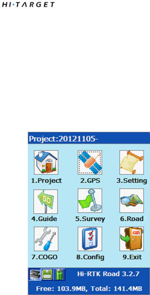
Mainframe Connecting
GPS —> Connect GPS, setup the HPC(Type of Controller), type, port,
baudrate and analyzer, click Connect. If connection is done, receiver
information window will display the receiver’s S/N.
Figure 4-1
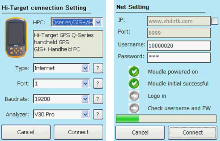
1. Network Connection
Figure 4-2
Note:
Only iRTK receiver can use the network connection function.
Input S/N of receiver and user password.
If failed, restart the receiver or the software on controller.
Static and Data Transmission
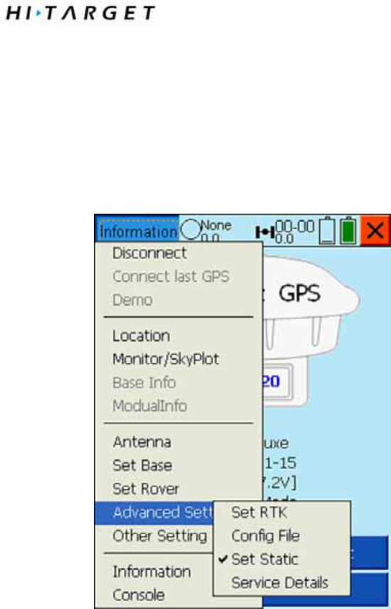
iRTK Operation
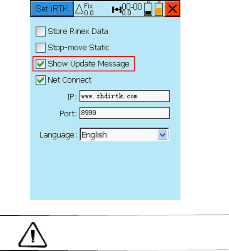
Before or in the surveying, you can use Hi-RTK installed in the controller to
set iRTK receiver to enable ”Show Update Message”, ”Store Renix
Data”, ”Stop-move Static”, ”Net Connect”,”Config File”, ”Set Static”, ”DIY
Voice”, ”Remote Connection”, etc.
Figure 4-5
iRTK Setup
”Store Renix Data”: enable instrument to record Renix data synchronously
in static mode.
”Stop-move Static”: enable instrument to support stop&go(PPK) function in
static mode.
”Show Update Message”: enable instrument to check new firmware version
automatically and prompt user to update.
Figure 4-6 Figure 4-7
Warning : Receiver will restart after the firmware’s
upgrade. Controller need to ”Disconnect GPS”
and ”Connect GPS” so that it can work regularly!
Static and Data Transmission
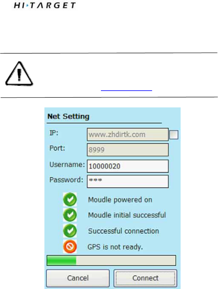
”Net Connect”: enable terminal control device to connect with receiver by
network. If it is disabled, software on the controller will prompt user that
instrument is not ready when it is online in the network.
Warning: In case of connection failed, in ”Net Connect”
Hi-Target suggest you to keep IP and Port number
default ! (IP: www.zhdrtk.com Port: 8999)
Figure 4-8
”DIY Voice”: Switch the language of the voice: Silent, Chinese, English and
User(user-definded)
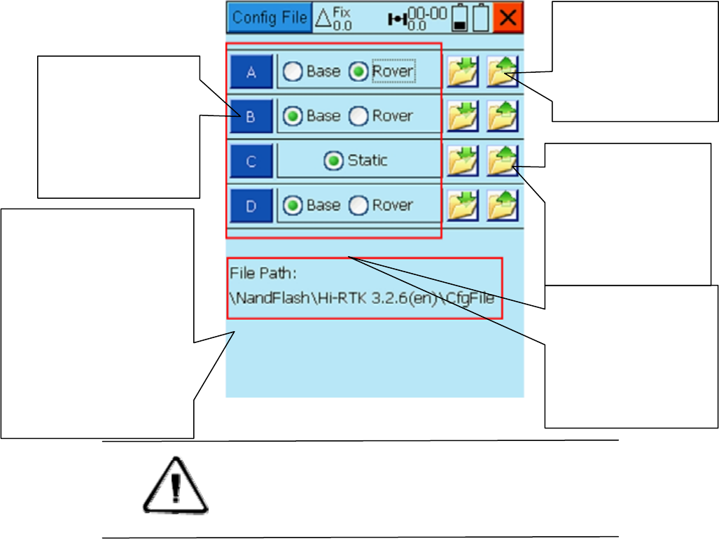
Config File
Figure 4-9
Warning: When the config file has been saved, you can apply
it to a receiver. But you should do an average for
the receiver which work in base mode before
starting a RTK surveying.
When your base is working in external readio mode, software
will prompt you to input the channel of the external radio after
you have save the configuration.
Save the current
configuration of the
receiver
Load the saved
configuration of
the receiver
Offer you 4 files
to save and load
configuration
You can share your
files by copying
them to other
controller’s ”CfgFil
e” folder.
Switch the work
mode when apply
the configuration
Static and Data Transmission
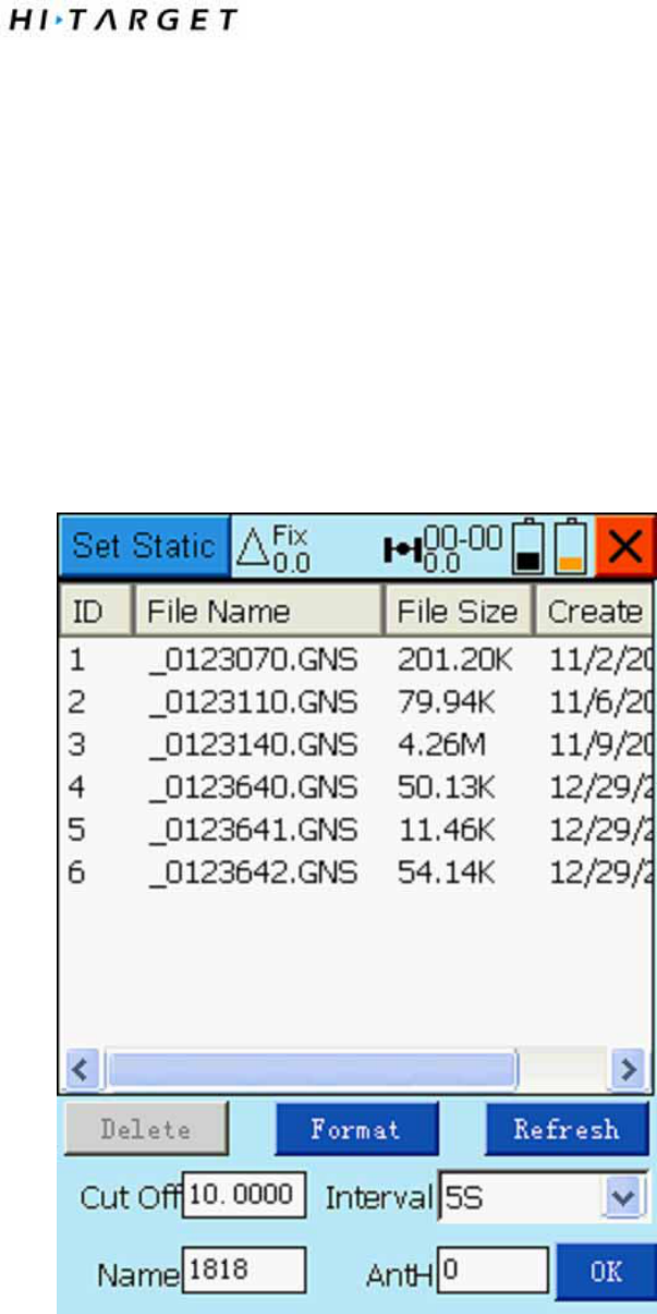
Set Static
Static collecting mode can offer you an easy way to see, delete files, format
and easy to set the elevation mask, interval, file name and antenna height, etc.
”OK”: To set elevation mask, interval, file name and antenna height and
switch the working mode into Static.
”Refresh”: To refresh the list.
”Delete”: To delete the static file.
”Format”: To format the data and impossible to recover
Figure 4-11

Warning: The data will not be recovered after the operation
of format or delete. So please make sure that all the
useful data have been copied to a safe place before you
do these operations.
Service Details
In this interface you can check the current functions that are authorized.
You can contact Hi-Target’s sales representative to get an upgrade to apply
more functions.

Static and Data Transmission
STATIC and DATA TRANSMISSION
Introduction of This Chapter
■ Introduction
■ Procedure of iRTK Static Survey
■ Download Data with U Disc Download
■ Remote Download Static Files
■ Management Software Operation For Static
Survey
Introduction
iRTK can be used as dual-frequency static surveying
instrument. You can double click F1, when the voice reminds
you, press power button to fix. After the setting is done, the red
status LED flashes once while collecting an epoch in a few
seconds (depends on the setting of sampling interval). The
collected static survey data is saved in the memory card of the
main frame. The static survey data have to be downloaded to
PC with post-processing software to be processed.
Procedure of iRTK Static Survey
1. Locate the instrument on a control point, do centering and
leveling.
2. Measure the height of instrument for three times, on
condition that the difference of each measuring is less than
3mm and the final height of the instrument should be the
average height. The height of instrument should be defined
from the controlling point of base centre to upper edge of
marker line. The antenna radius of iRTK receiver is 0.087
meter; the height of phase center is 0.0765 meter.
Instrument height
measur point

Static and Data Transmission
Fig 5-1
3. Record point name, instrument S/N, instrument height,
observing initiated time
4. Turn on the instrument and set the main frame as static
surveying mode. The satellite LED flashing means the
instrument is searching the satellites. The satellites are fixed
once the satellite LED turns into constant on. Status LED
flashes due to your collection interval set. The default
collection interval is 5 seconds, which means an epoch will be
collected every 5 second. In static mode, the receiving LED is
off.
5. Turn off the instrument after the static survey is done and
record the turn-off time.
6. Download and post-process data
Note: Don’t move the tribrach nor change the collecting set while the
instrument is collecting data.
Download Data with U Disc Download
iRTK saves the files with U disc download in file management,
i.e. you can download the files by drag-drop. The static survey
data only can be downloaded but not to re-write the data.
The data of iRTK receiver ca n be downloaded in U disc
download, you can use Y type data cable, connect one side to
USB port of PC and the other side to the 8-core jack of main
frame. After connected, RTK iRTK new disk symbol shows up
in the PC, like U disc download, you can copy the according
files directly.
Fig 5-2
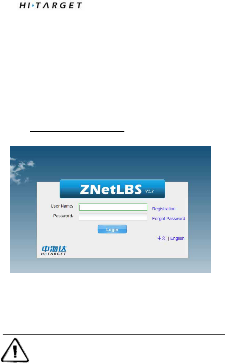
Download static files to modify the naming and antenna height
steps:
1. Choose *.GNS static file and double click mouse;
2. Choose [GNS Modify program], pop-up “File edit”, we can
edit point name and antenna height, for sure click [OK].
Fig 5-4
Note: The series port can’t be downloaded in U disc download, but to delete
static data of iRTK receiver.
Static and Data Transmission
Remote Download Static Data Files
After the end of the static job, the user can operate the control
panel buttons: ultra-long press F2, click F1 timely upload
collected static data files. Remote operator from control center
can use HI-TARGET LBS server to synchronization download
the data then processed.
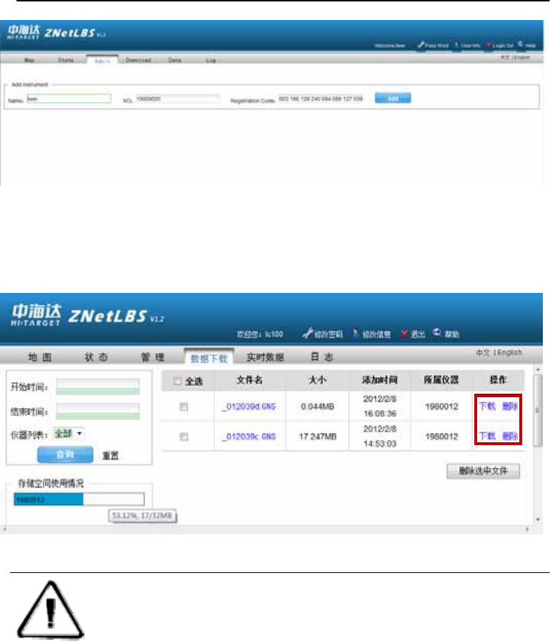
HI-TARGET LBS server static data file download steps:
1. Login http://www.zhdlbs.com:81, Sign up for new users
(first use)
Fig 5-5
2. Login system, "Management Add iRTK instrument number
and registration code, instrument alias fill any character length
is less than six characters or blank is empty.
Attention: The instrument of which serial number is 7 digits, the first
number of receivers in the LBS registered instrument should +1.
For example, the receiver Serial No. 6,980,012, and then fill in
the instrument No.: 7,980,012;
The instrument of which serial number is 8 digits, then directly input the
digits. For example, the receiver Serial No. 19000010, and then fill in the
instrument No.: 19000010.
Fig 5-6
3. Choose [Data download], you can do static files download,
delete and other operations.
Fig 5-7
Attention: 1. Receiver serial number (S / N) in the receiver
bottom of the label, the purchase of equipment will
be given the corresponding version of the registration
code.
2. Delete static data from network is only remove static data files stored
in the LBS server and does not delete the static files in the receiver.

Static and Data Transmission
Management Software Operation For Static
Survey
The main function of static file management software of IRTK
receiver:
◇ Delete original data
◇ Delete and format the whole
◇ Read parameters, Set parameters
Operating steps:
1. Connect Y type data cable to 8-pin port of iRTK receiver
and the series port of PC
2. Choose the right PC port and click “connect port”
3. Refresh list, the observation data files will be in the list
4. File name: 8 digit character: the first chart is replaced by
underline; the second, third, and forth are the last two numbers
of S/N number of the receiver from which the data is collected;
the fifth, sixth, and seventh is the year-accumulated-date; the
last chard is the collecting period of the day
5. Set up time: GNSS time.
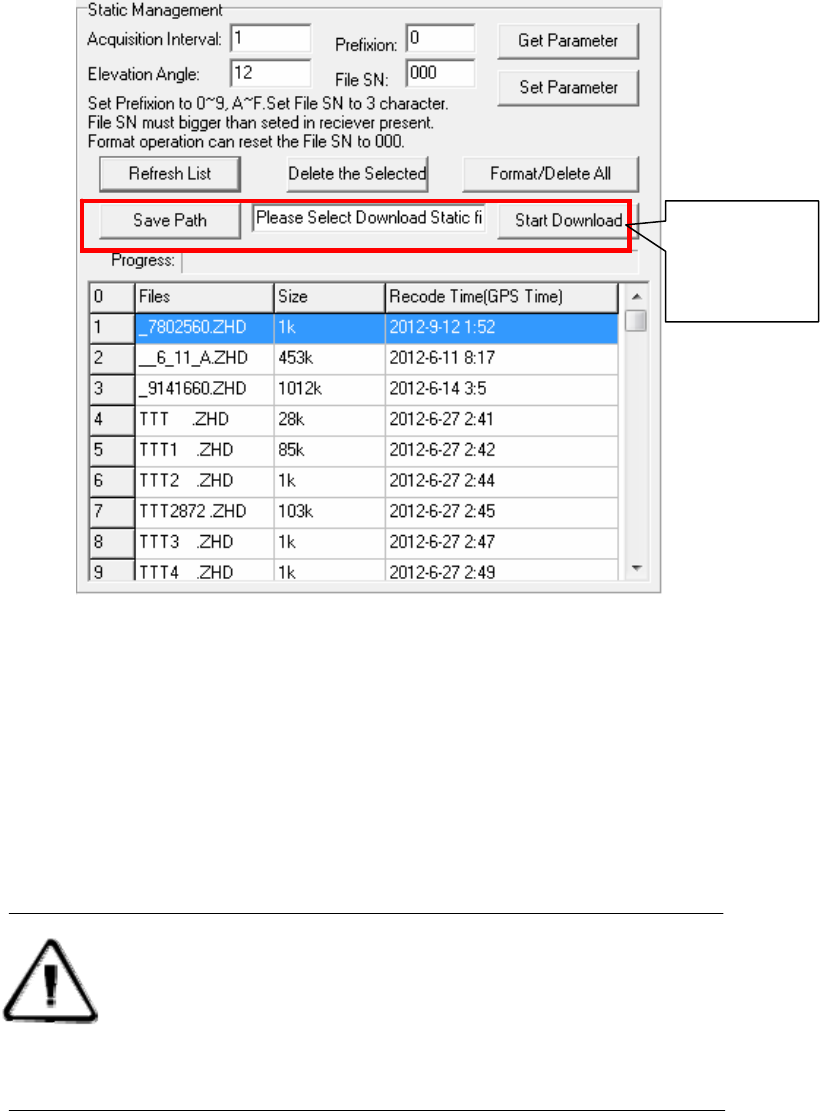
Fig 5-8
6. Delete data: choose the data need to be deleted, click delete
files.
7. Change collecting interval and satellite cutoff/elevation
angle: input value and click set parameters. Click read
parameters to view the original collecting interval and satellite
cutoff angle.
Attention: GPS receiver Management software V1.3.6 is a Universal
Edition, and is fit for A/V/F/H/iRTK series GNSS receivers. iRTK
don’t support port download of static files, it’s useless when you
use iRTK!
iRTK don’t
support port
download

Attachment 3 iRTK Parameters
Technical Parameters
Introduction of This Chapter
■ Introduction
■ Receiver
■ Interface Part
■ Function Key and Indicator Led
■ Intelligent Voice Module
■ Accuracy
■ Physical Feature
■ Environment
Introduction
Here we list out all Technical Parameters of iRTK GNSS RTK
SYSTEM. The Technical Parameters will be a little different
according to your purchase order. Please make sure about your
configuration then find out Technical Parameters
correspondingly.
Receiver
Trimble-BD970
◇ 220 channels
◇ GPS : Synchronous tracking L1 C/A, L2E, L2C, L5
◇ GLONASS : Synchronous tracking L1 C/A, L1 P,
L2 C/A(only for GLONASS M) and L2P
◇ SBAS: Synchronous tracking L1 C/A, L5
◇ GIOVE-A:synchronous tracking L1 BOC, E5A,
E5B and E5AltBOC(optional )
◇ GIOVE-B:synchronous L1 CBOC, E5A, E5B and
E5AltBOC(optional)GALILEO:(Upgrade)
◇ Trimble Maxwell 6 of advanced user-defined GNSS
Technology
◇ A high precision measurement in the relevant organs
using 9 for global navigation satellite system
◇ Very low noise GNSS carrier phase in Surveying,
Accuracy < 1 mm within 1 HZ wide band
◇ Mature low elevation-angle tracking technology

Attachment 3 iRTK Parameters
◇ Initialization time < 10 S
◇ Initialization Reliability > 99.9%
◇ 1 Hz, 2 Hz, 5 Hz, 10 Hz, 20Hz and 50 Hz output
(default 10Hz)
◇ Differential data format: CMR, CMR+, RTCM 2.1,
2.2, 2.3, 3.0, 3.1
◇ Navigation Output Format: ASCII :
NMEA-0183 GSV, AVR, RMC, HDT, VGK, VHD, ROT,
GGK, GGA, GSA, ZDA, VTG, GSTPJT, PJK, BPQ, GLL,
GRS, GBS and binary system:Trimble GSOF
Function Key and LED
◇ 3 Panel buttons: 1 power switch key, 2 functional
keys, with these combination you can set all the function with
voice and Indicator Led flexibility
◇ 3 LEDs: 1 Satellite LED (Single color), 1
Communication LED ( Dual Color), 1 Power LED (Dual
Color)
Intelligent Voice Module
With broadcasting function for each operation and status
checking
Accuracy
◇ Static, Fast Static: Horizontal: ±(2.5+1×10⁻⁶D) mm
Vertical: ±(5+1×10⁻⁶D) mm
RTK Accuracy: Horizontal: ±(10 +1×10⁻⁶D) mm
Vertical: ±(20 +1×10⁻⁶D) mm
◇ PPP Accuracy: Horizontal: ±10cm
Vertical: ±10cm
Physical Feature
◇ With ARM9 Corn Control Chip, built-in 1G Flash
Memory
◇ Dimension: φ19.5cm×h10.4cm
◇ Weight: 1.7kg( Incl. li-ion battery)
◇ Anti-impact from 3 meters nature fall, can float and
waterproof in 2 meters deep water
◇ Internal Li-ion battery. With 2 standard battery in
5000 mAh , Voltage:7.4 V; One Single battery working
continuously time: 14 hours in static mode, 9 hours in GPRS
mode, and 8 hours in 2W transmitting power
◇ 6~30V external DC power supported, external and
internal power supply exchanged automatic
◇ Receiver Power Consumption (Static mode): 2.5W
Environment
◇ IP Standard: IP67, waterproof, completely
dust-proof and anti-impact.
◇ Working temperature: -45℃~65, storage
temperature: -55℃~85℃
◇ 100% Humidity non-condensin