High Flying Electronics Technology HF-A11X Embedded WIFI module User Manual HF A11x Rev5
High-Flying Electronics Technology Co.,Ltd Embedded WIFI module HF A11x Rev5
UserManual.wiki
>
High Flying Electronics Technology
>
HF A11X User Manual
HF-A11x User Manual_Rev5
Navigation menu
Upload a User Manual
Namespaces
Wiki Guide
HTML
PDF
Info
Views
User Manual
Discussion / Help
Navigation
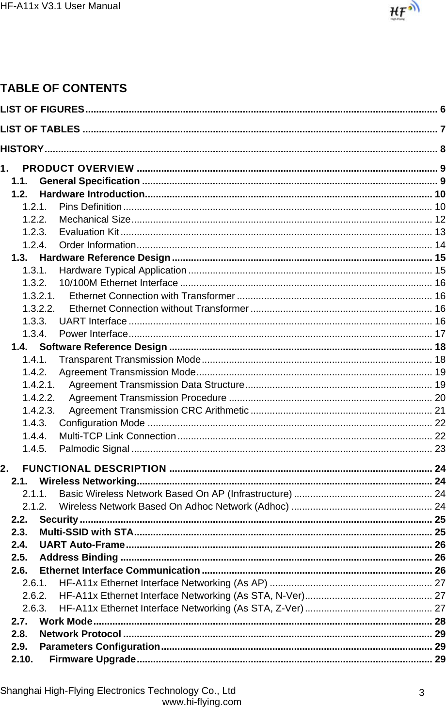
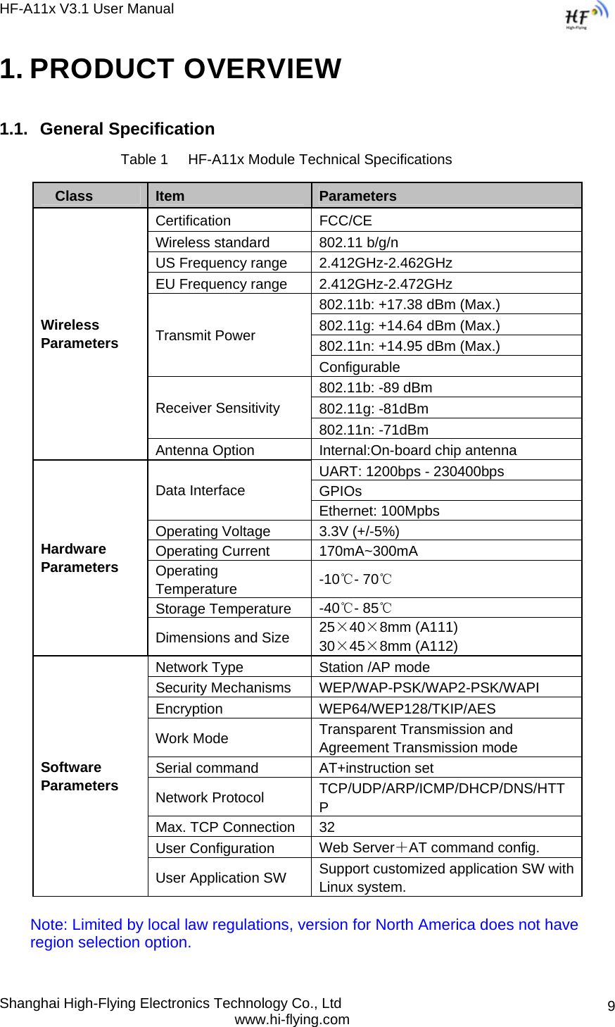
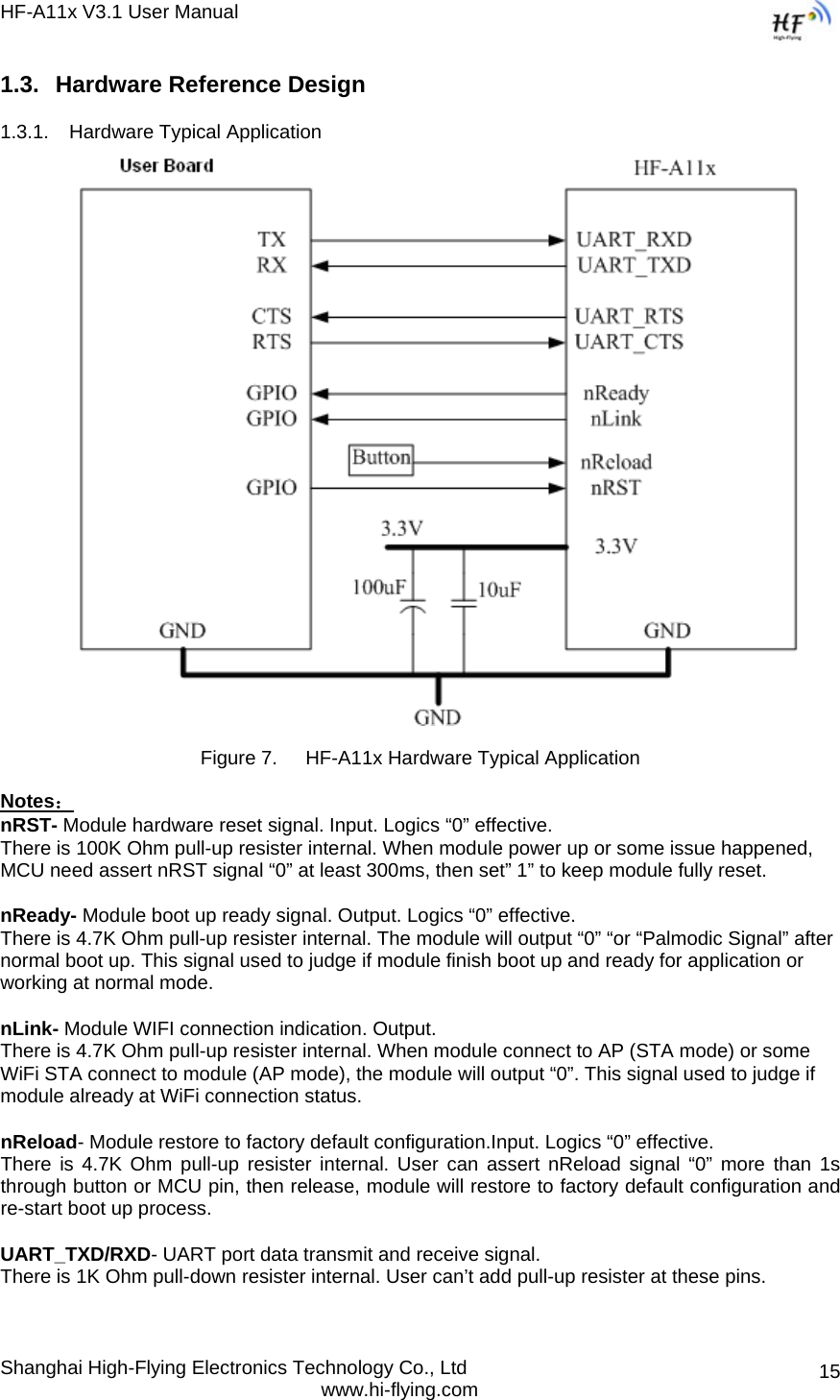
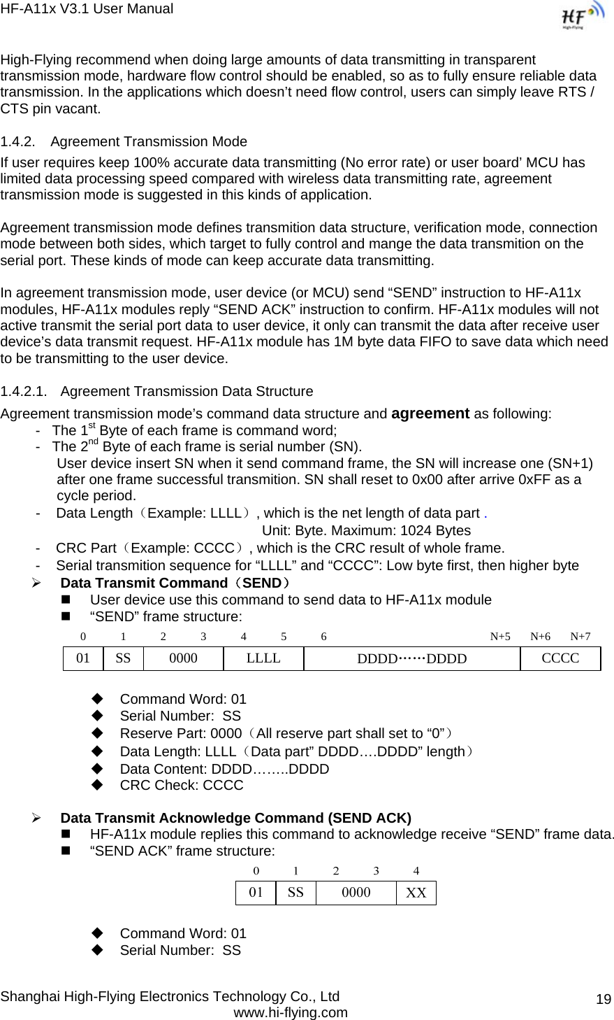
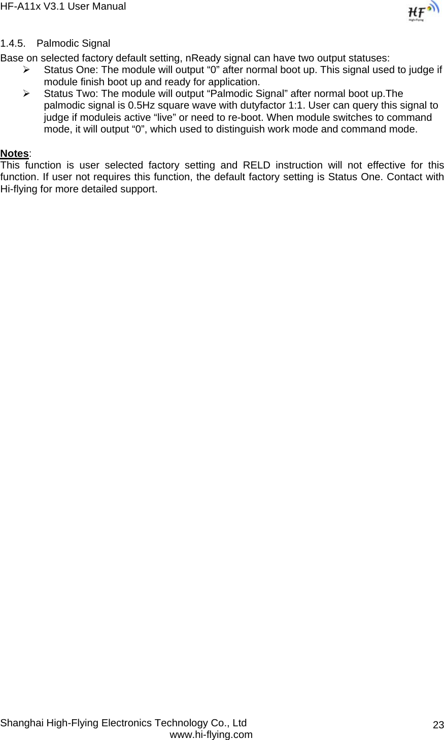
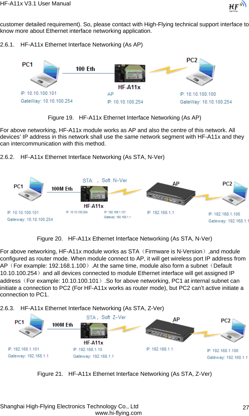
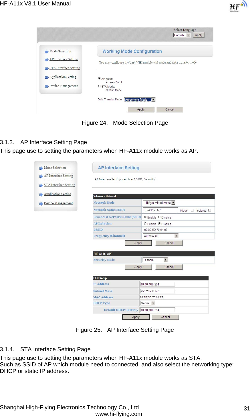
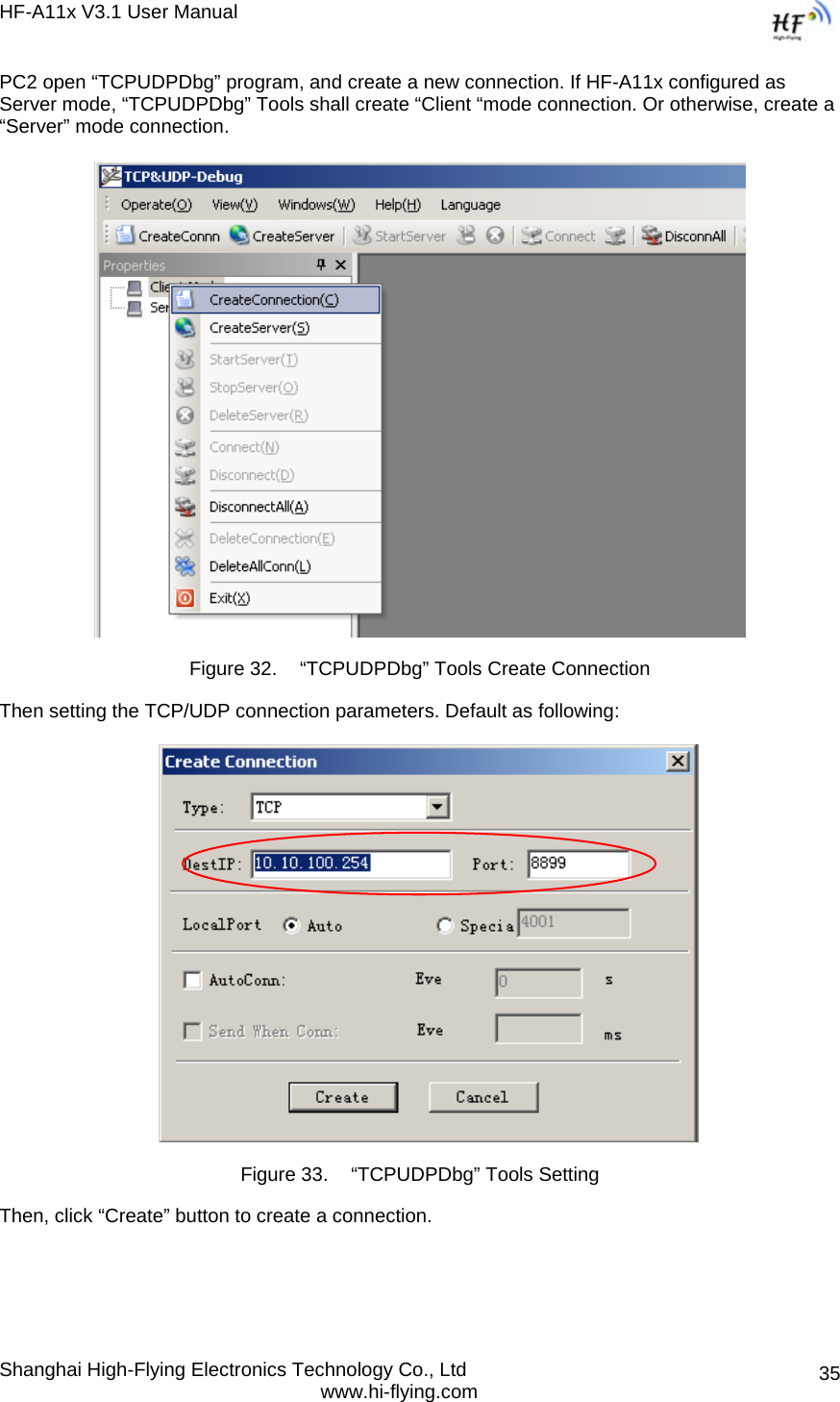
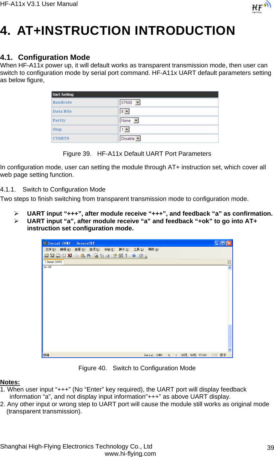
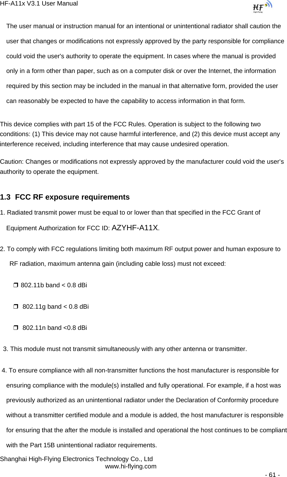
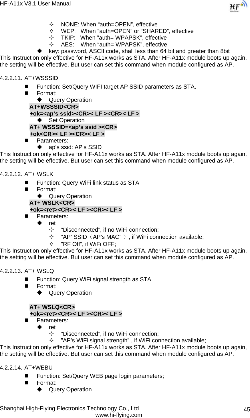
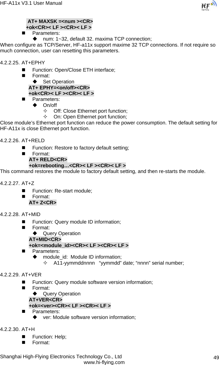
![HF-A11x V3.1 User Manual Shanghai High-Flying Electronics Technology Co., Ltd www.hi-flying.com 404.2. AT+ Instruction Set Overview User can input AT+ Instruction through hyper terminal or other serial debug terminal, also can program the AT+ Instruction to script. User can also input “AT+H” to list all AT+ Instruction and description to start. Figure 41. ”AT+H” Instruction for Help 4.2.1. Instruction Syntax Format AT+Instruction protocol is based on the instruction of ASCII command style, the description of syntax format as follow. ¾ Format Description < >: Means the parts must be included [ ]: Means the optional part ¾ Command Message AT+<CMD>[op][para-1,para-2,para-3,para-4…]<CR> AT+: Prefix of command message; CMD: Command string; [op]: Symbol of command operator, “=” : The command requires parameters input; “NULL”: Query the current command parameters setting; [para-n]: Parameters input for setting if required; <CR>:”Enter” Key, it’s 0x0a or 0x0d in ASCII; Notes: When input AT+Instruction, “AT+<CMD>” character will display capital letter automatic and other parts will not change as you input. ¾ Response Message +<RSP>[op] [para-1,para-2,para-3,para-4…]<CR><LF><CR><LF> +: Prefix of response message;](https://usermanual.wiki/High-Flying-Electronics-Technology/HF-A11X/User-Guide-1661752-Page-40.png)
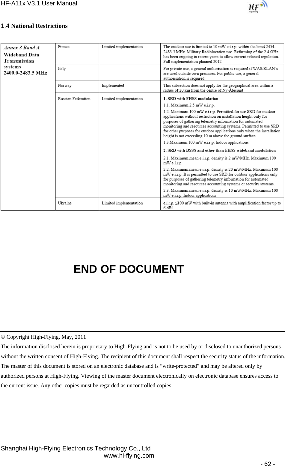
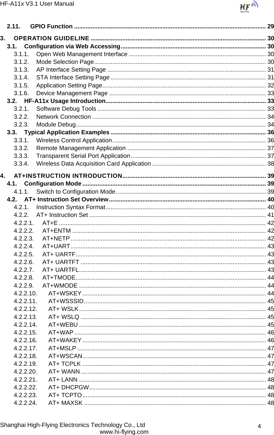
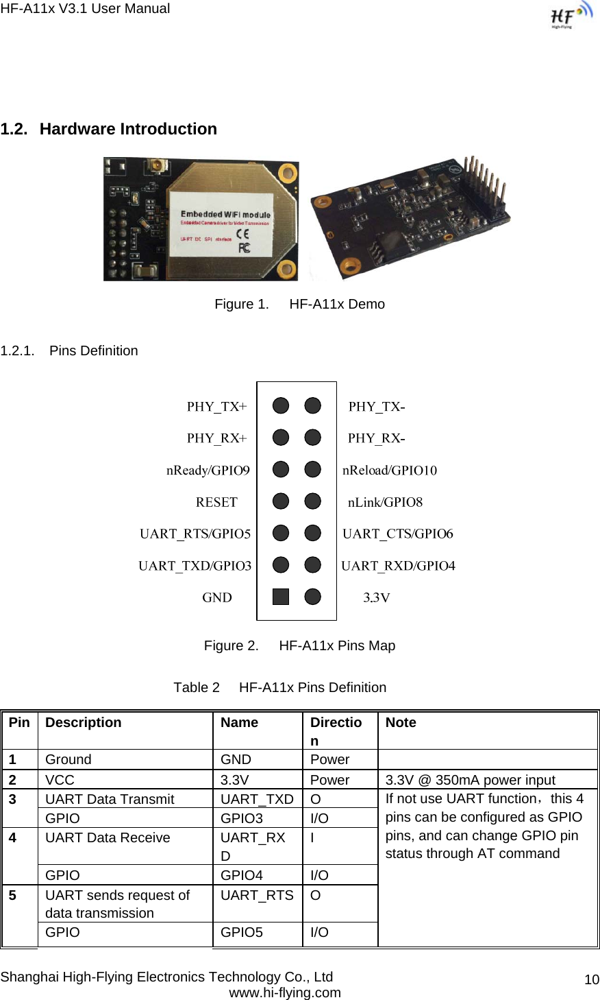
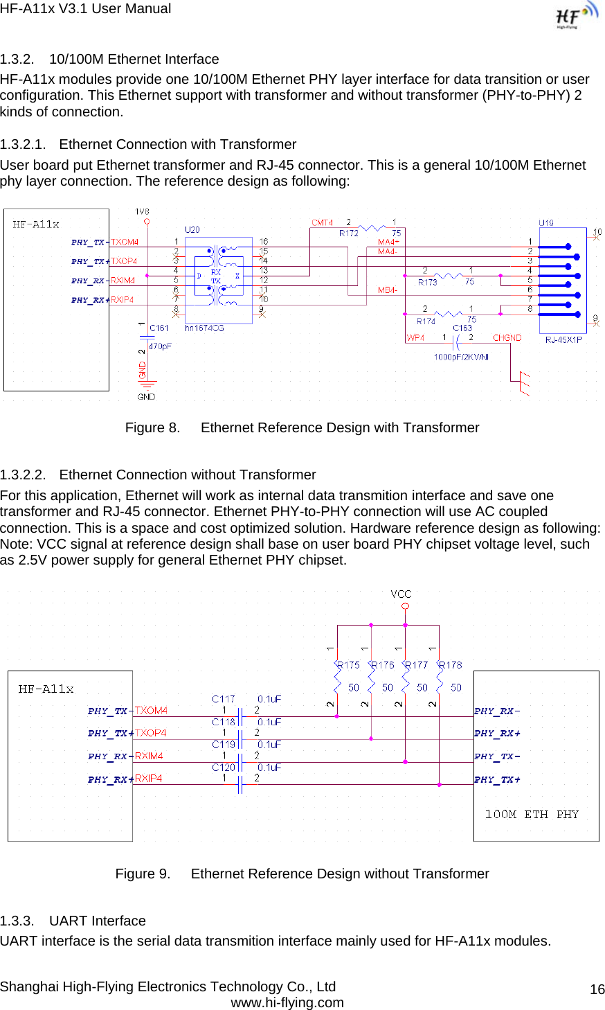
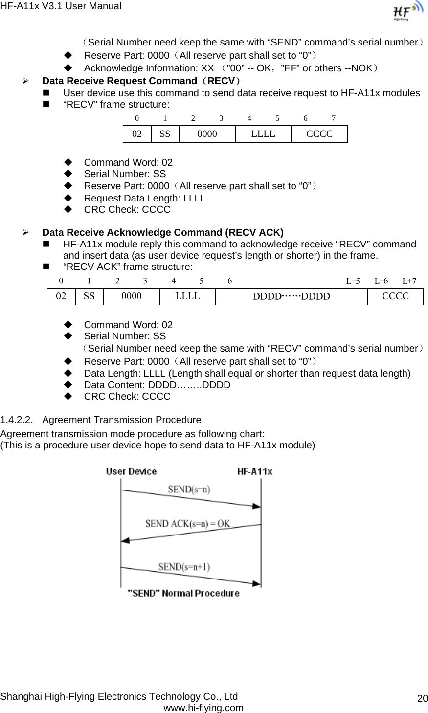
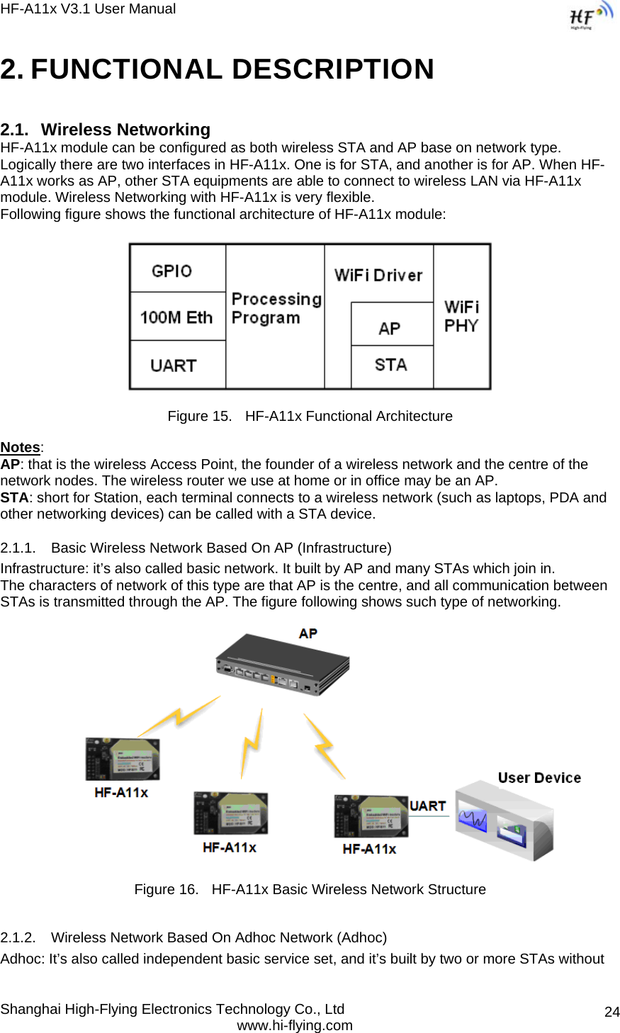
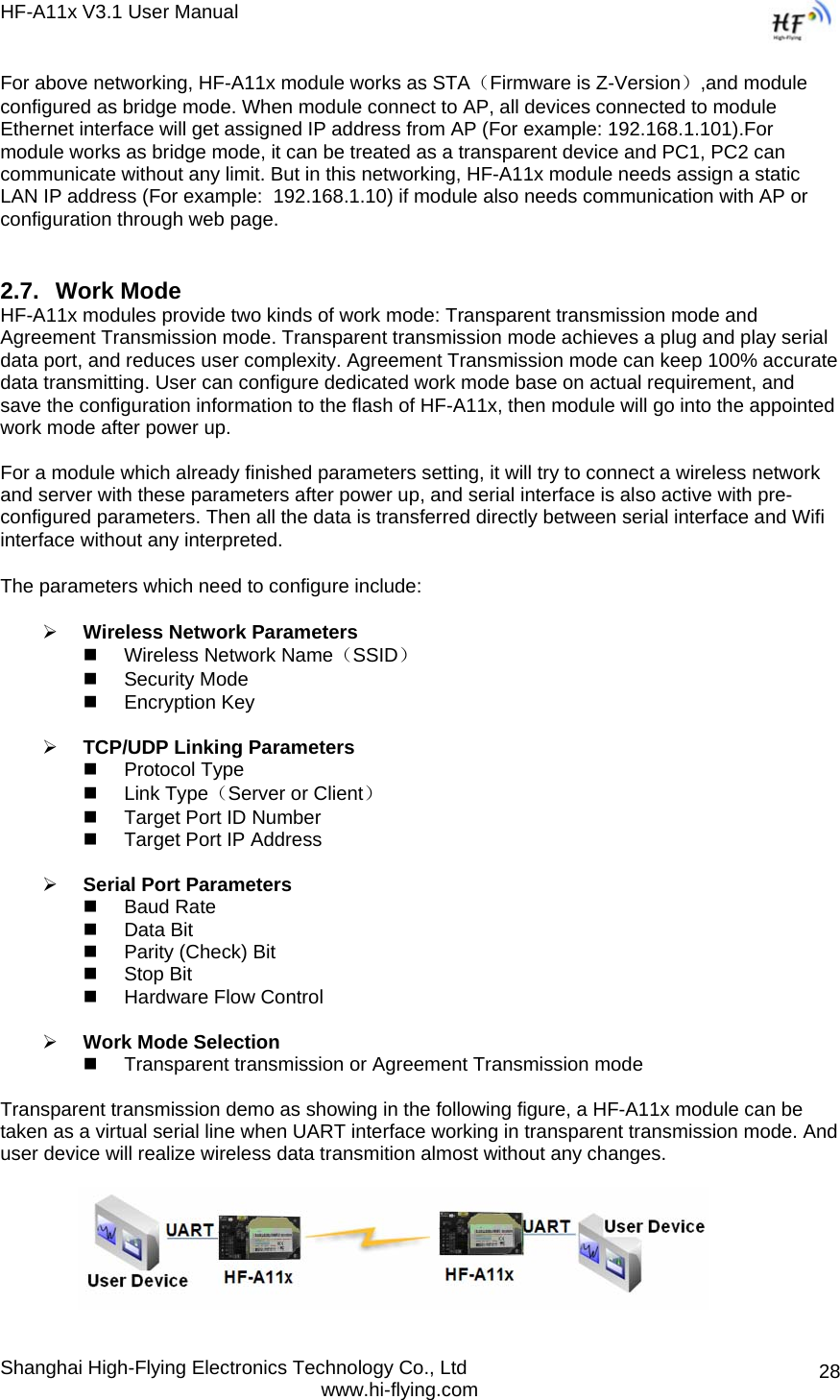
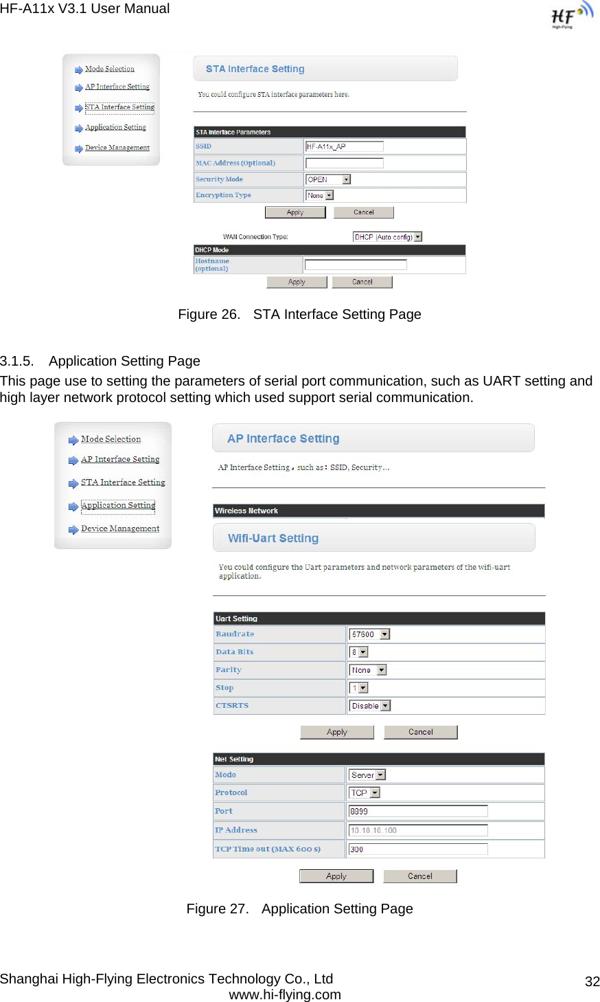
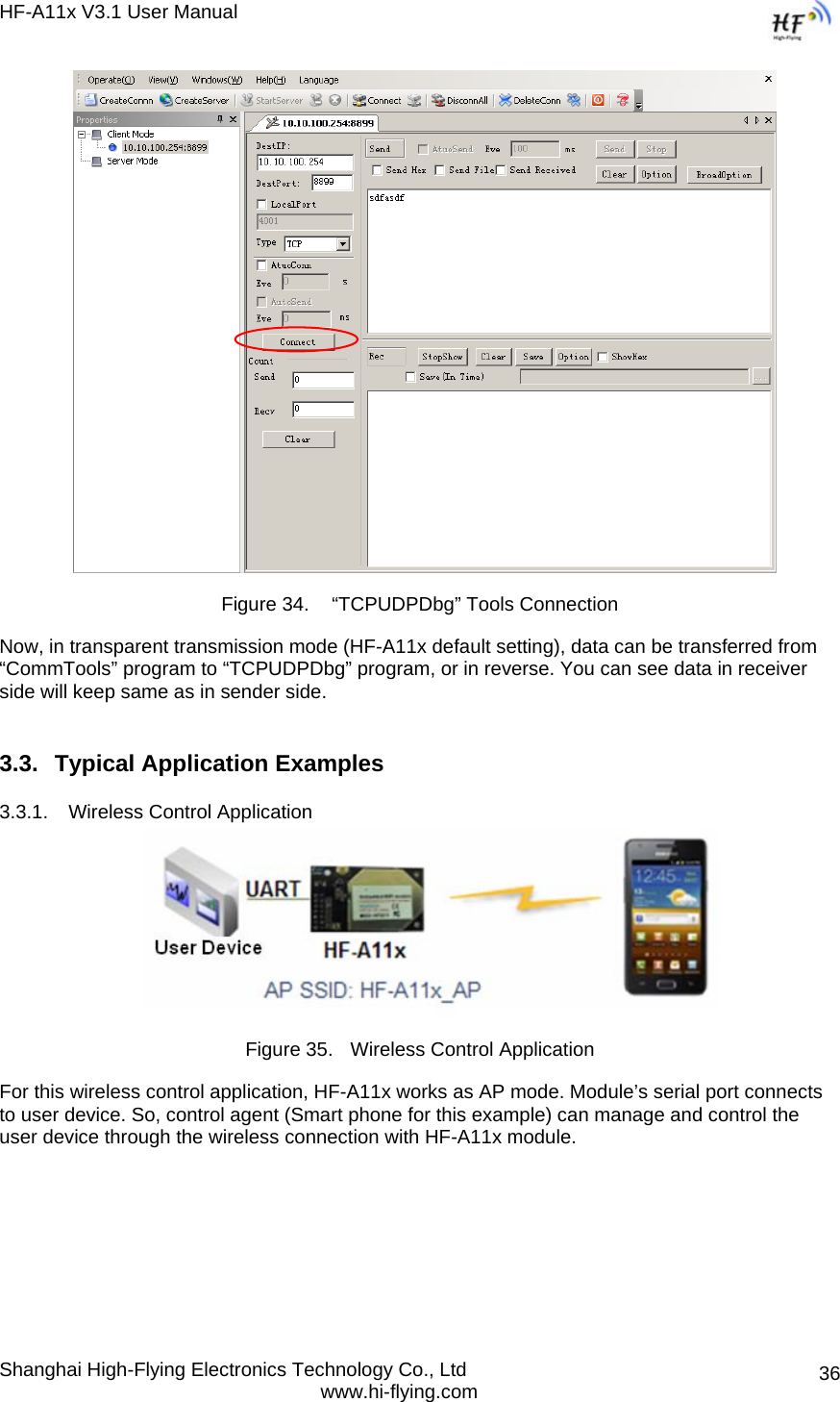
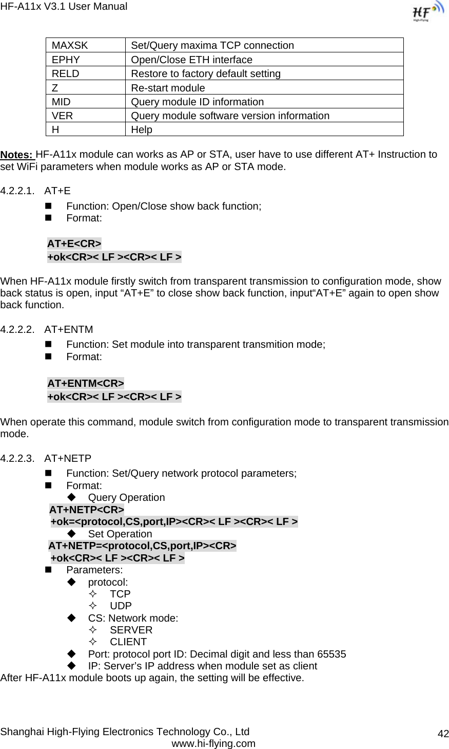
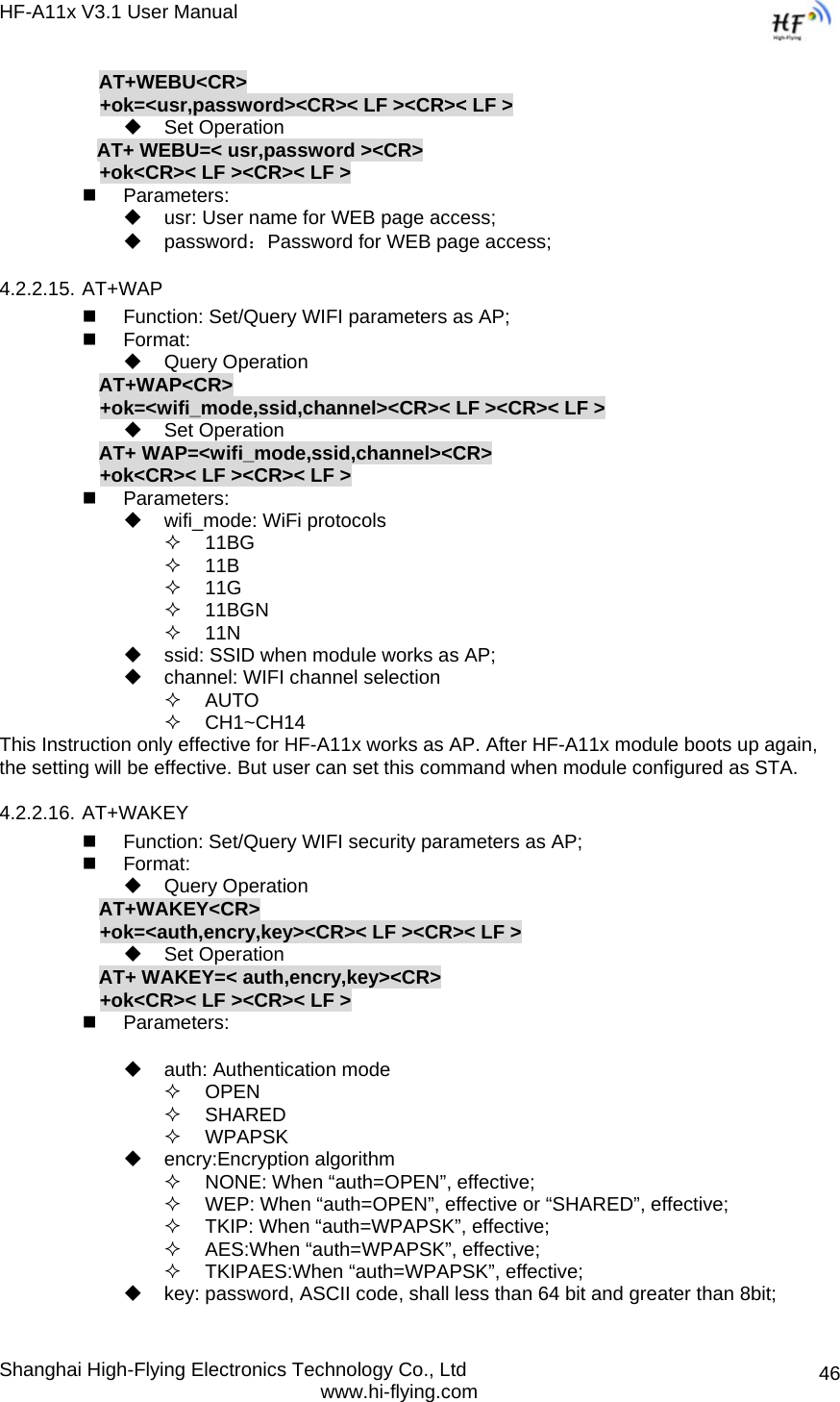
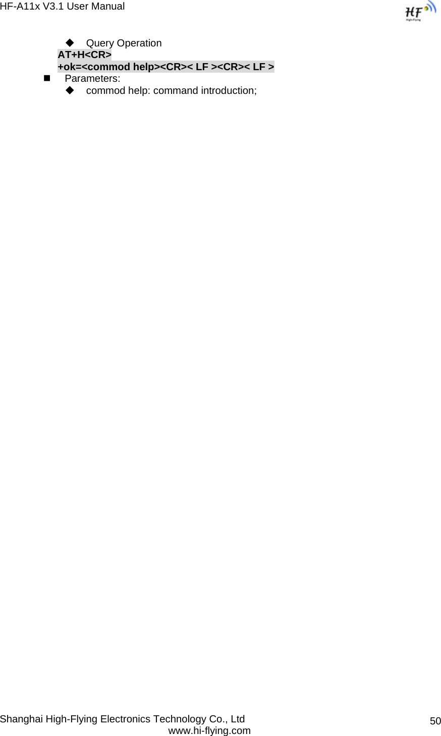
![HF-A11x V3.1 User Manual Shanghai High-Flying Electronics Technology Co., Ltd www.hi-flying.com 41 RSP: Response string; “ok” : Success “ERR”: Failure [op] : = [para-n]: Parameters if query command or Error code when error happened; <CR>: ASCII 0x0d; <LF>: ASCIII 0x0a; ¾ Error Code Table 5 Error Code DescribtionHF-A11x Web Access Default Setting Error Code Description -1 Invalid Command Format -2 Invalid Command -3 Invalid Operation Symbol -4 Invalid Parameter -5 Operation Not Permitted 4.2.2. AT+ Instruction Set Table 6 AT+ Instruction Set List Instruction Description <null> NULL E Open/Close show back function ENTM Set module into transparent transmition mode NETP Set/Query network protocol parameters UART Set/Query serial port parameters UARTF Open/Close UART auto-frame function UARTFT Set/Query UART auto-frame trigger time UARTFL Set/Query UART auto-frame trigger length TMODE Set/Query data transmition mode (transparent transmition or agreement transmition) WMODE Set/Query WIFI work mode (AP or STA) WSKEY Set/Query WIFI security parameters as STA WSSSID Set/Query WIFI target AP SSID parameters as STA WSLK Query WiFi link status as STA WSLQ Query WiFi signal strength as STA WEBU Set/Query WEB page login parameters (User Name and Password) WAP Set/Query WIFI parameters as AP WAKEY Set/Query WIFI security parameters as AP MSLP Set modules into power save mode.(Turn OFF WiFi) WSCAN Seek AP when module works as STA mode TCPLK Query if TCP link already build-up WANN Set/Query WAN setting, only effective as STA mode LANN Set/Query LAN setting, only effective as AP mode DHCPGW Set/Query DHCP gateway address TCPTO Set/Query TCP timeout](https://usermanual.wiki/High-Flying-Electronics-Technology/HF-A11X/User-Guide-1661752-Page-41.png)
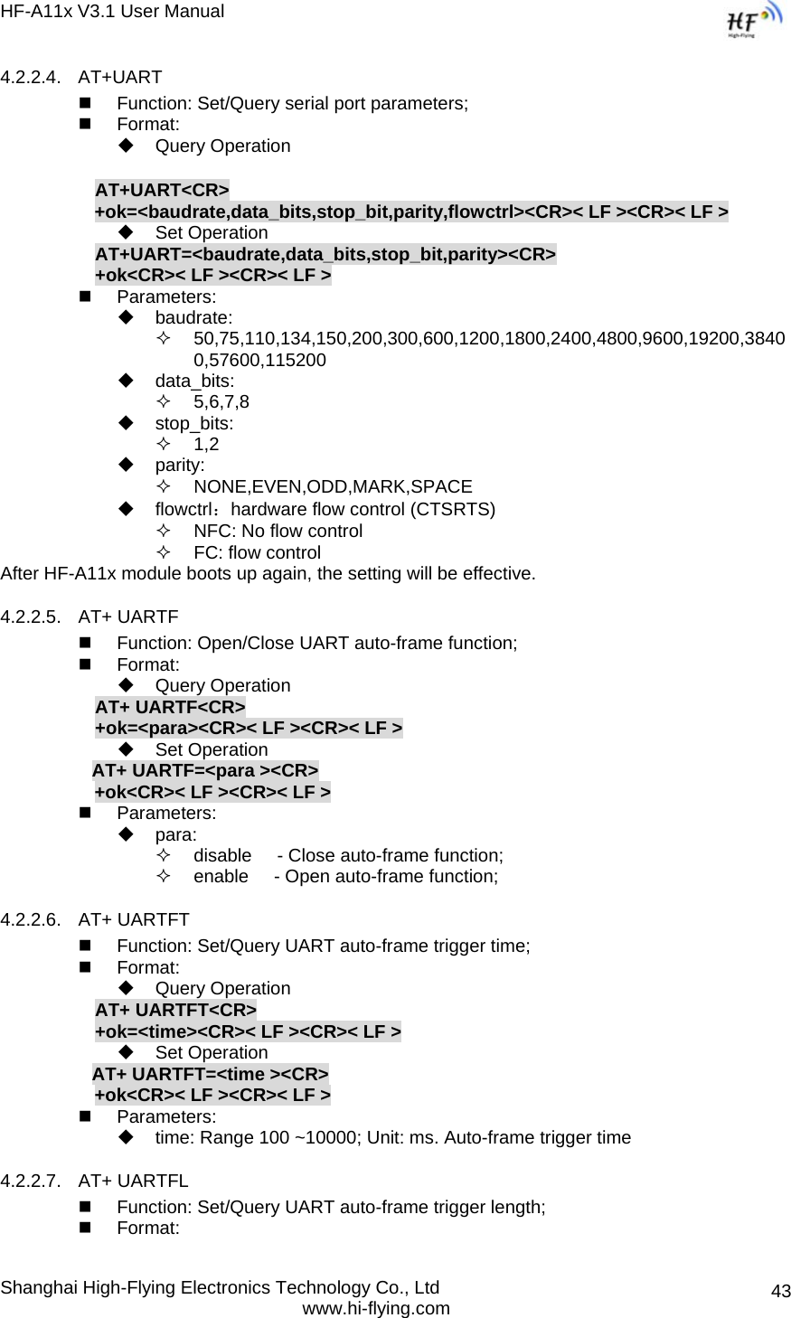
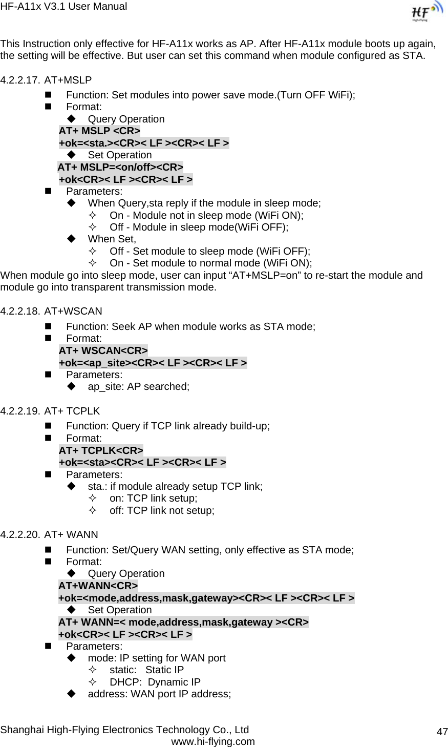
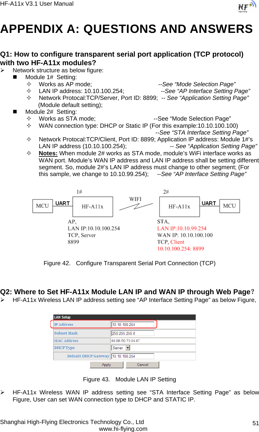
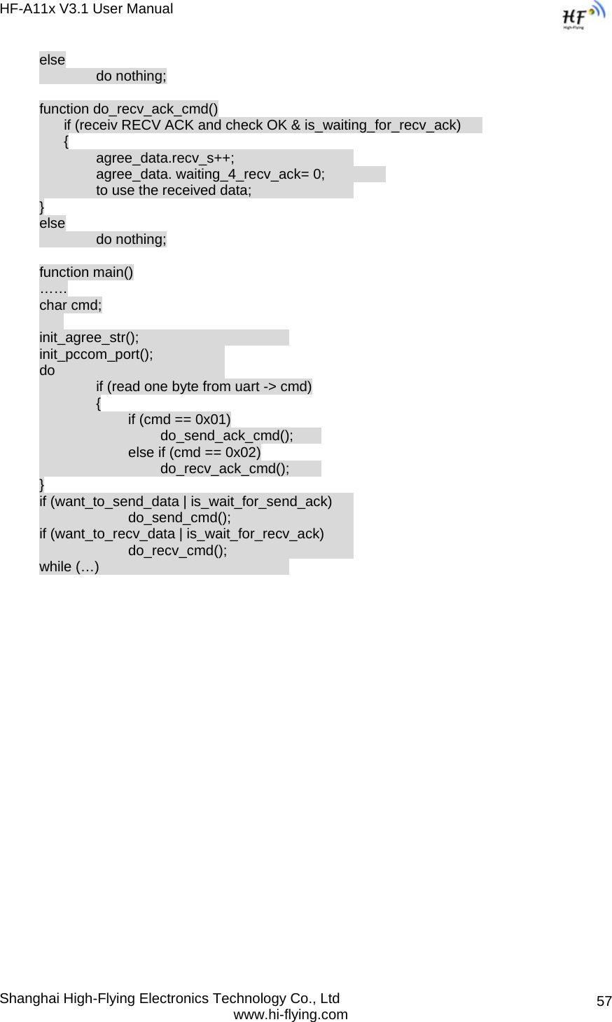
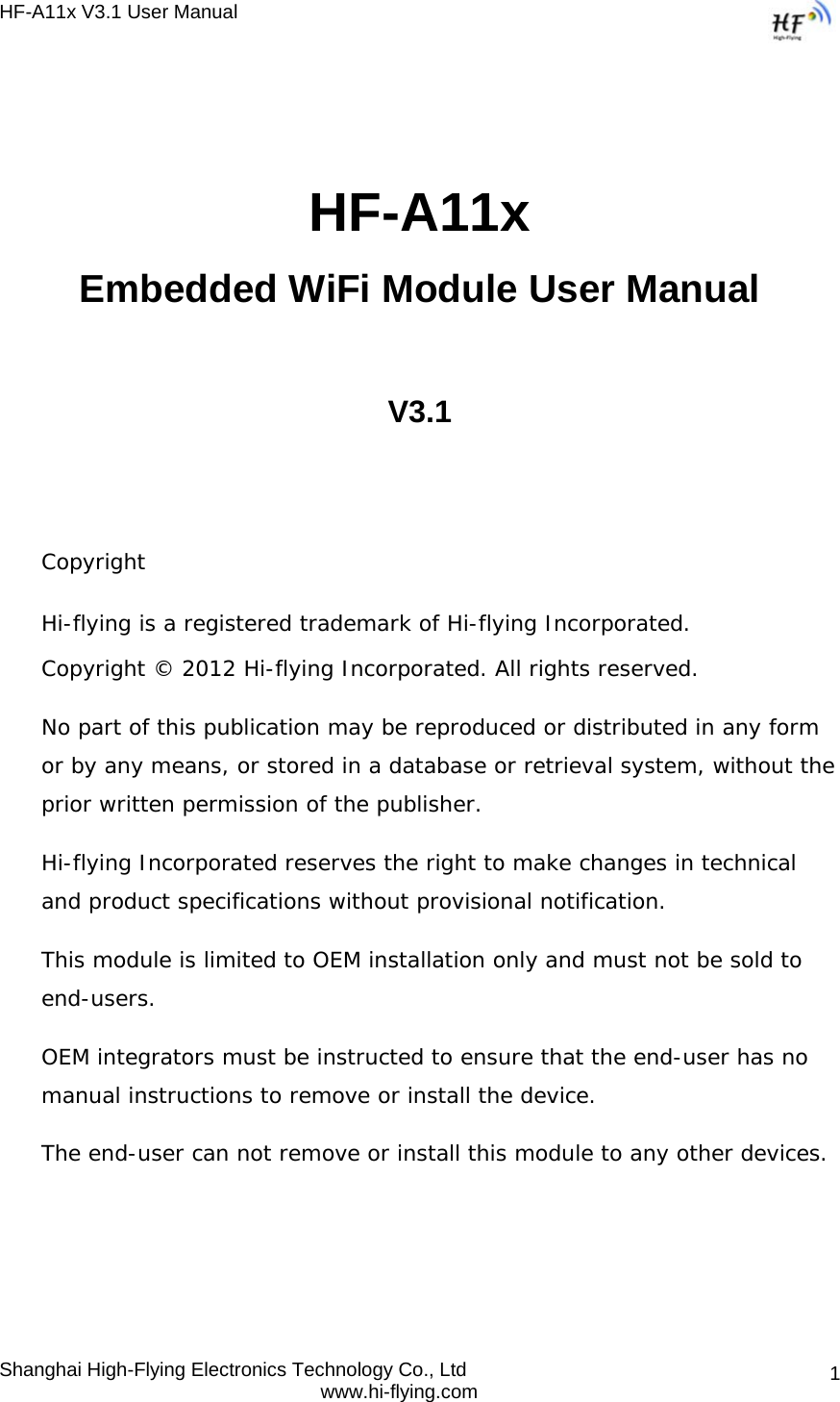
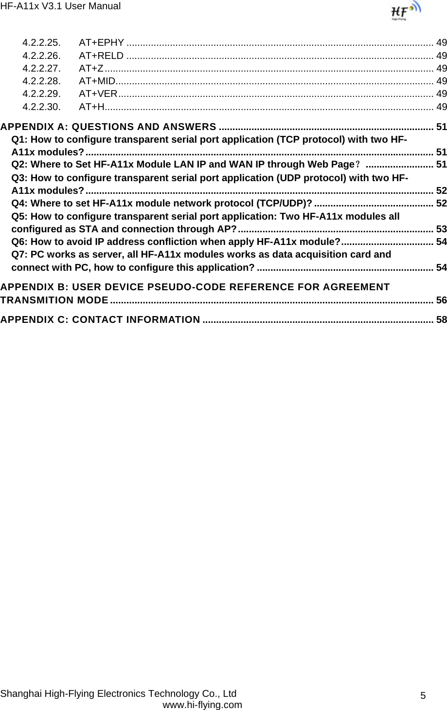
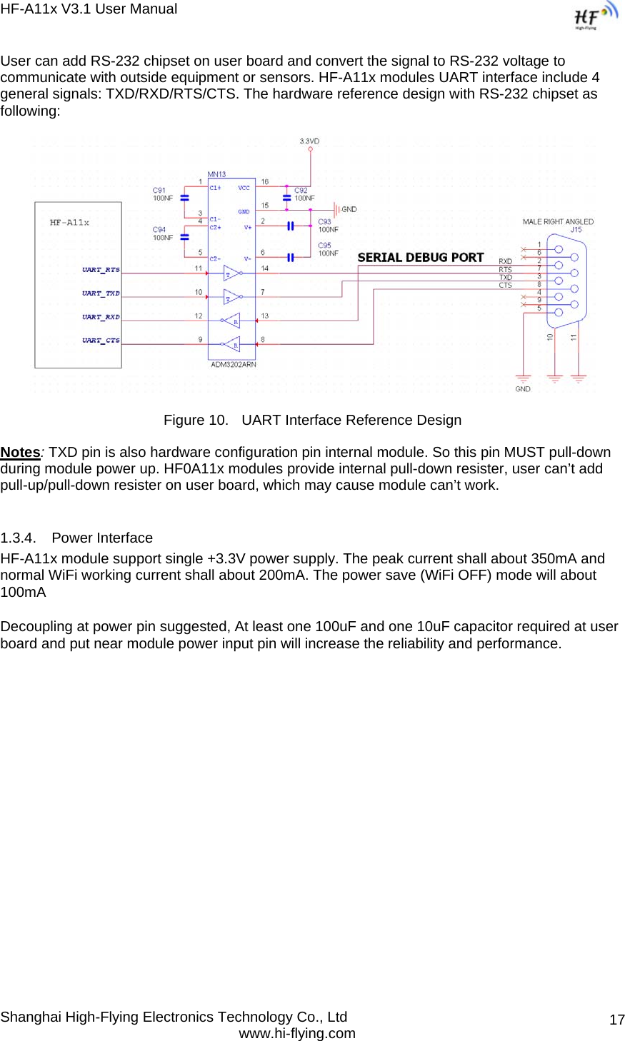
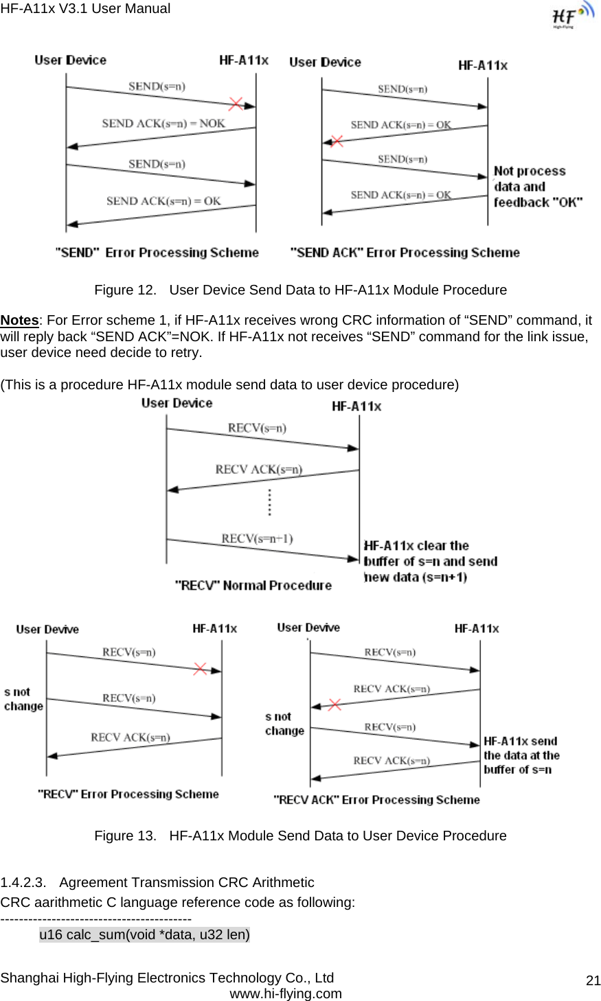
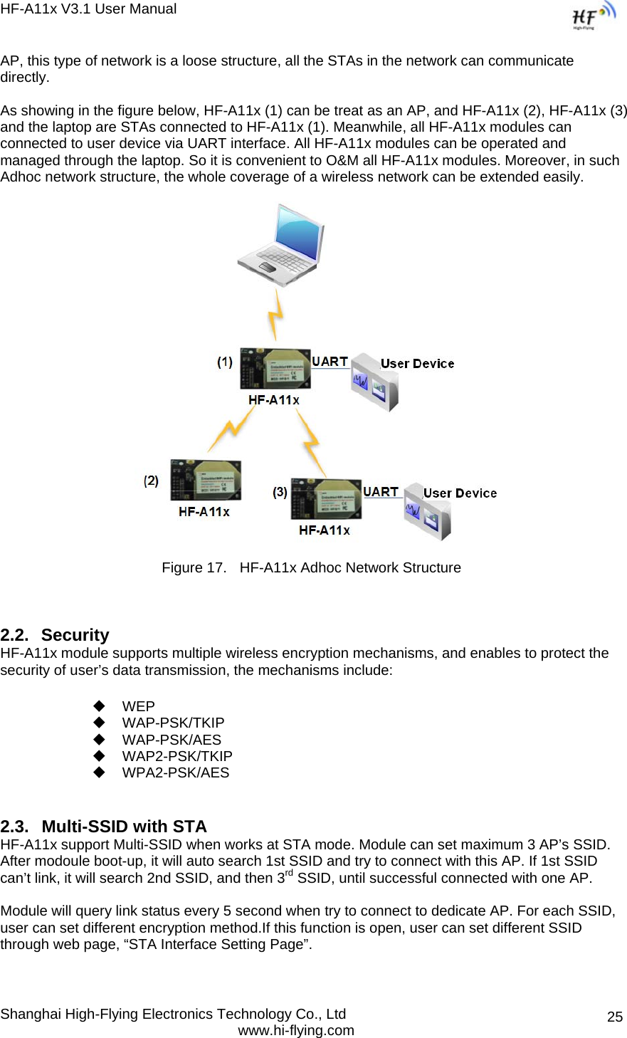
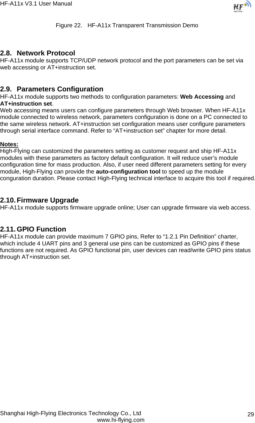
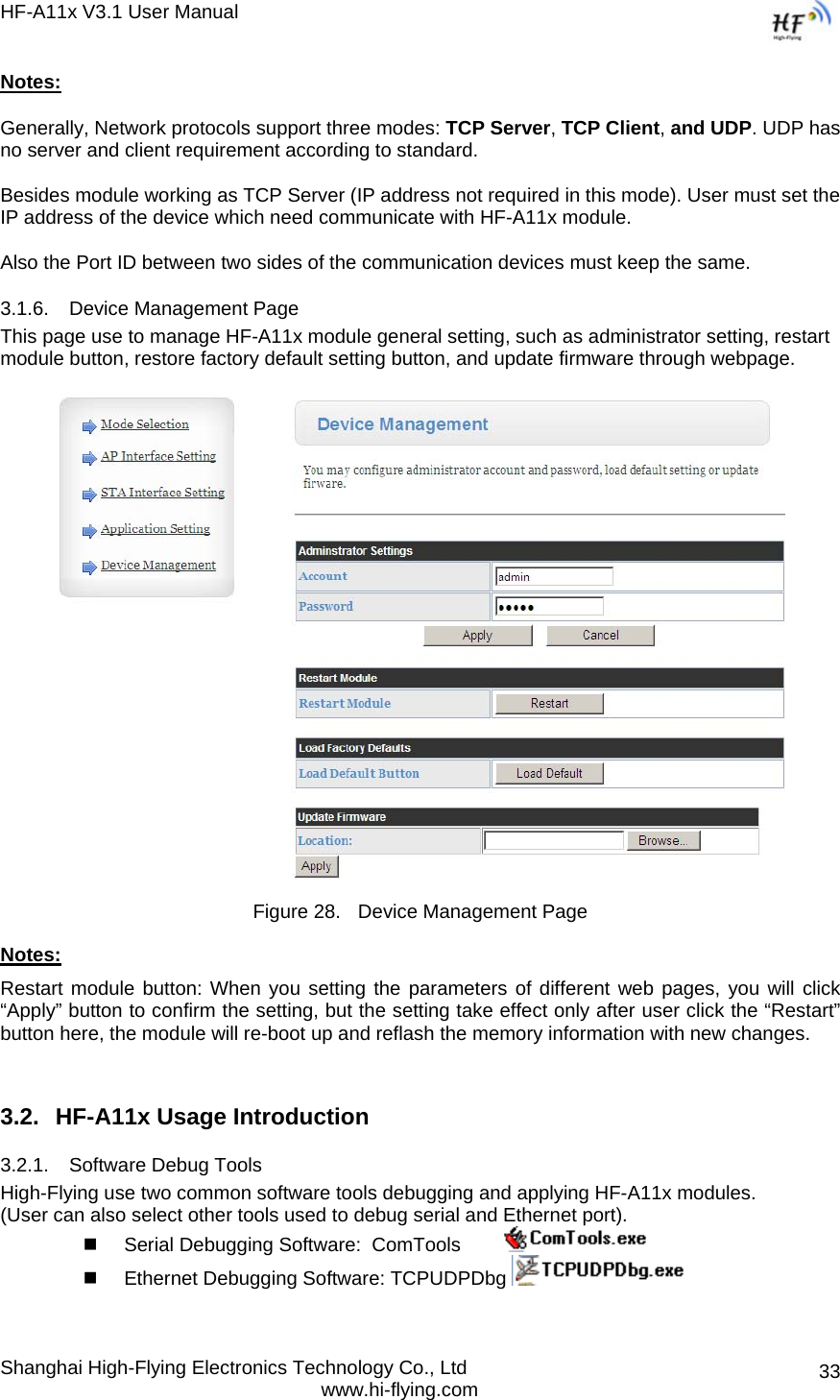
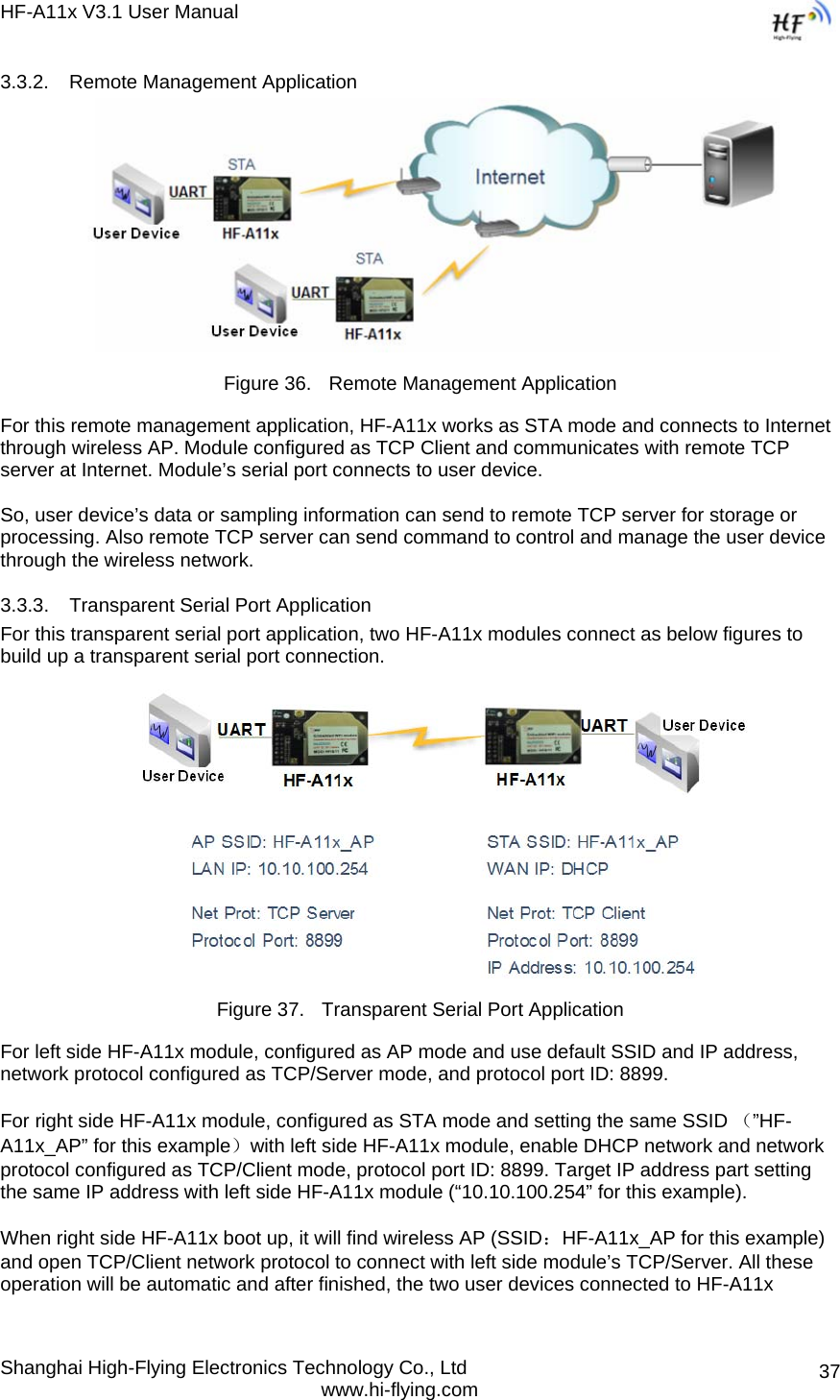
![HF-A11x V3.1 User Manual Shanghai High-Flying Electronics Technology Co., Ltd www.hi-flying.com 56APPENDIX B: USER DEVICE PSEUDO-CODE REFERENCE FOR AGREEMENT TRANSMITION MODE #define MAX_DAT_BUF_LEN 1024 #define AGREE_HEAD_LEN 6 #define MAX_SEND_CMD_LEN MAX_ DAT_BUF_LEN+8 #define RECV_CMD_LEN AGREE_HEAD_LEN+2 // Define data structure struct STRAGREE { // SEND 命令 unsigned char send_cmd[MAX_SEND_CMD_LEN]; unsigned short send_len; unsigned char send_s; int waiting_4_send_ack; // RECV 命令 unsigned char recv_cmd[RECV_CMD_LEN]; unsigned short recv_len; unsigned char recv_s; int waiting_4_recv_ack; } agree_data; function do_send_ cmd() if (is_waiting_for_send_ack & is_timeout) send_cmd_out(); else if (!is_waiting_for_send_ack) { generate_new_send_cmd(); send_cmd_out(); } else add waiting time; function do_recv_cmd() if (is_waiting_for_recv_ack & is_timeout) recv_cmd_out(); else if (!is_waiting_for_recv_ack) { generate_new_recv_cmd(); recv_cmd_out(); } else add waiting time; function do_send_ack_cmd() if (receiv SEND ACK and check OK & is_waiting_for_send_ack) { agree_data.send_s++; agree_data. waiting_4_send_ack= 0; }](https://usermanual.wiki/High-Flying-Electronics-Technology/HF-A11X/User-Guide-1661752-Page-56.png)