High Flying Electronics Technology HF-A21-SMT Embedded Wi-Fi Module User Manual
High-Flying Electronics Technology Co., Ltd. Embedded Wi-Fi Module
UserManual.wiki
>
High Flying Electronics Technology
>
HF A21 SMT User Manual
User manual
Navigation menu
Upload a User Manual
Namespaces
Wiki Guide
HTML
PDF
Info
Views
User Manual
Discussion / Help
Navigation
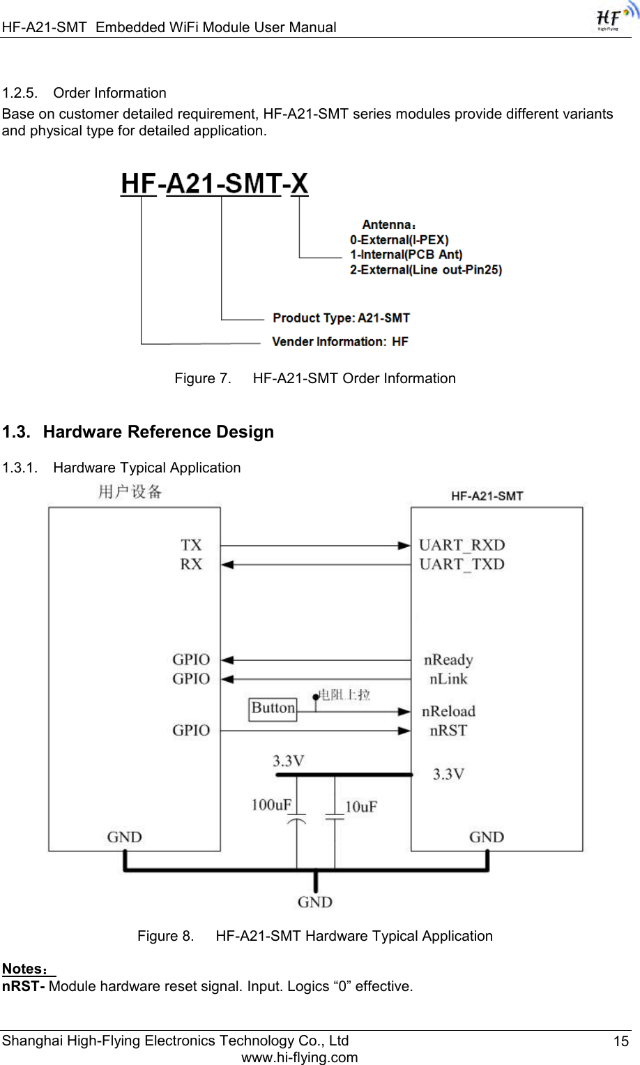
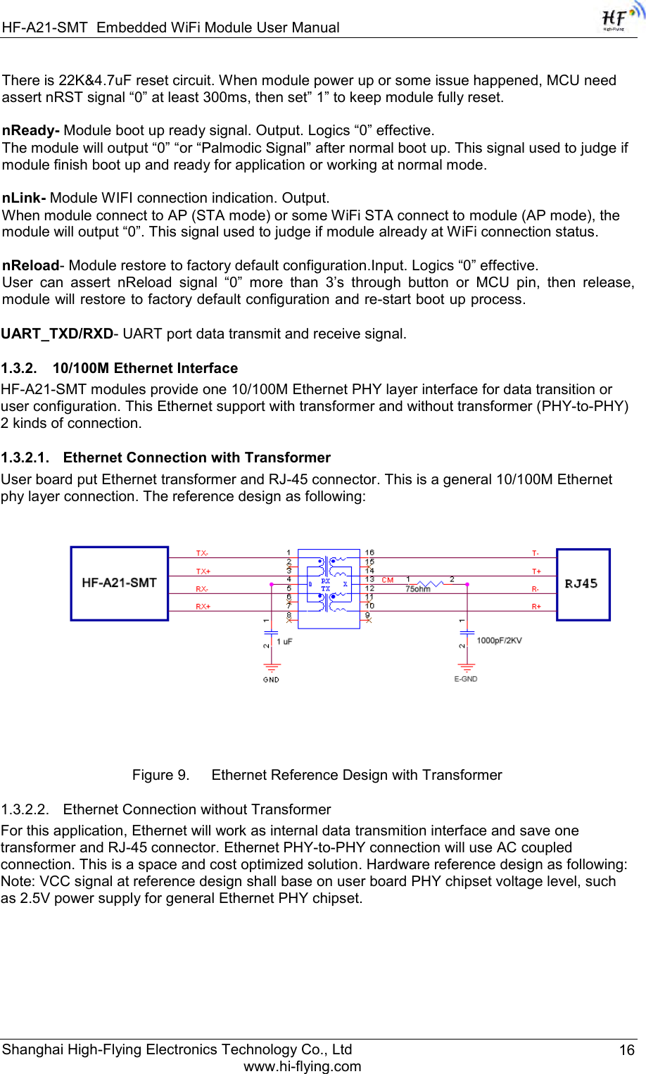
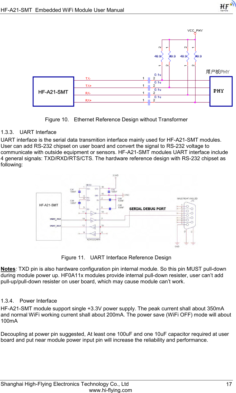
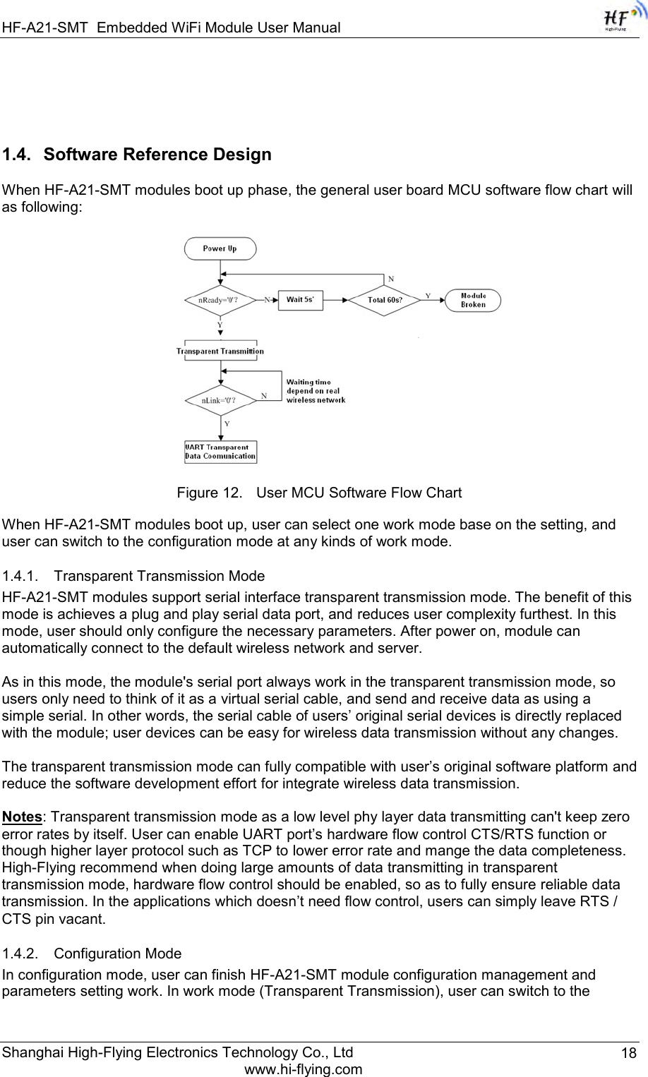
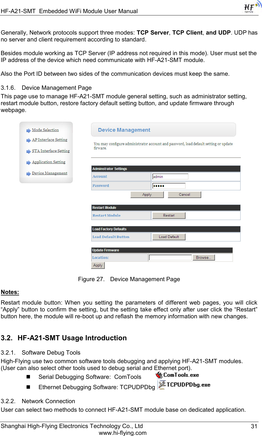
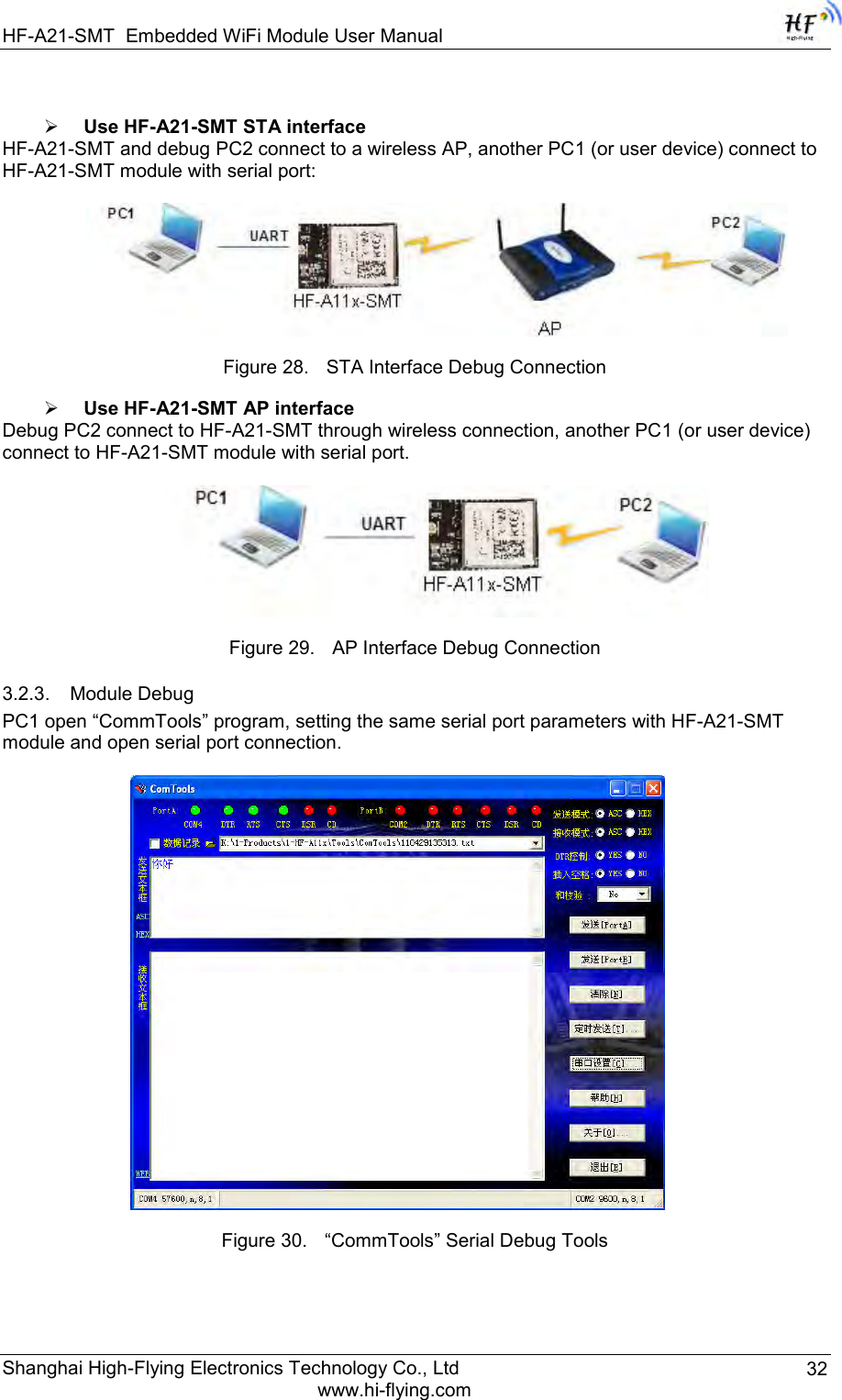
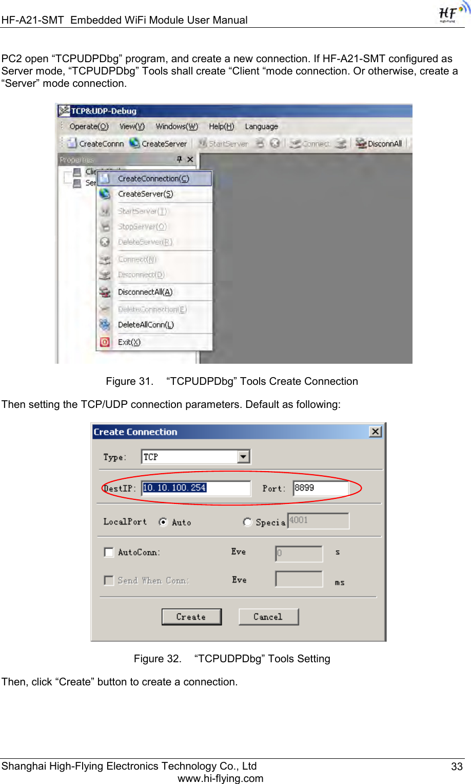
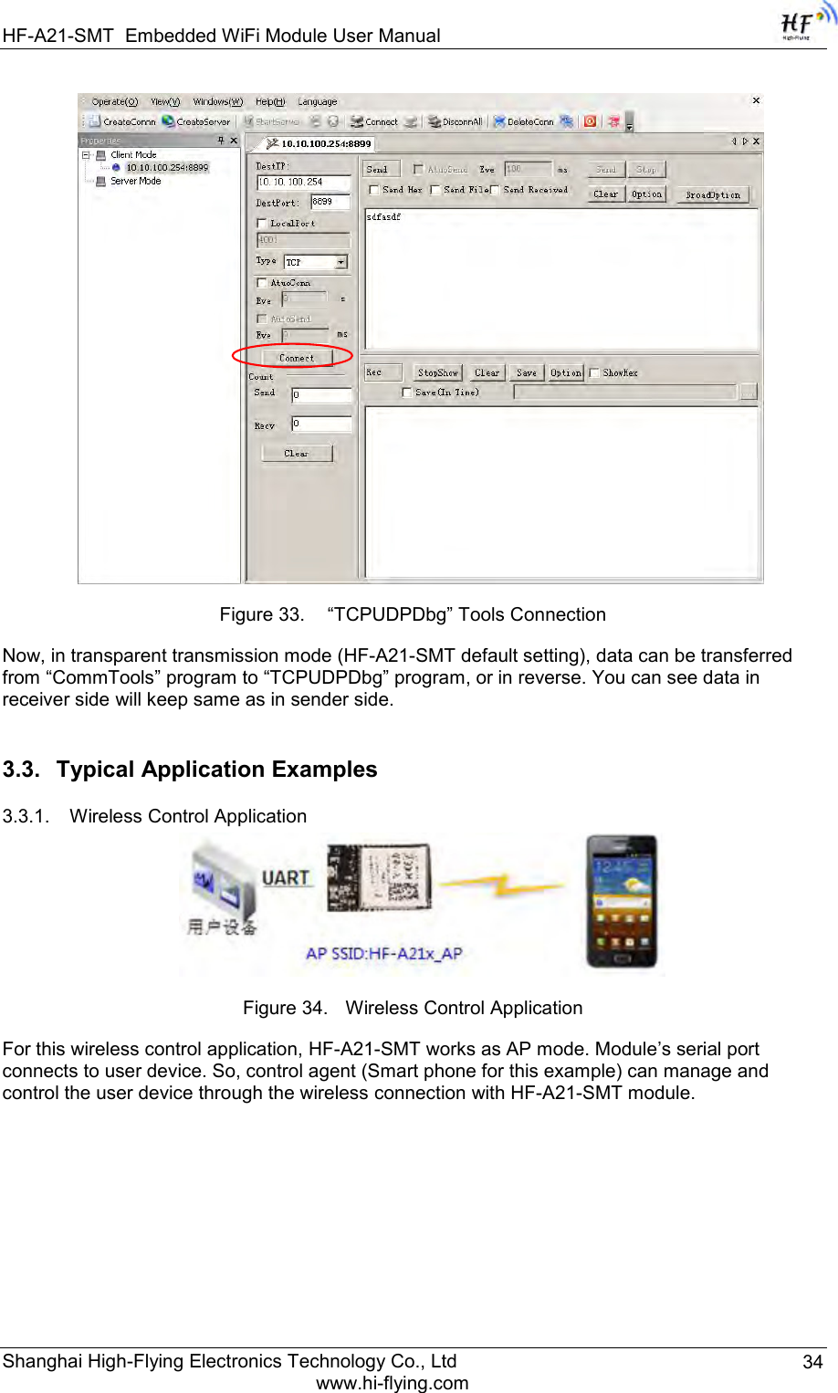
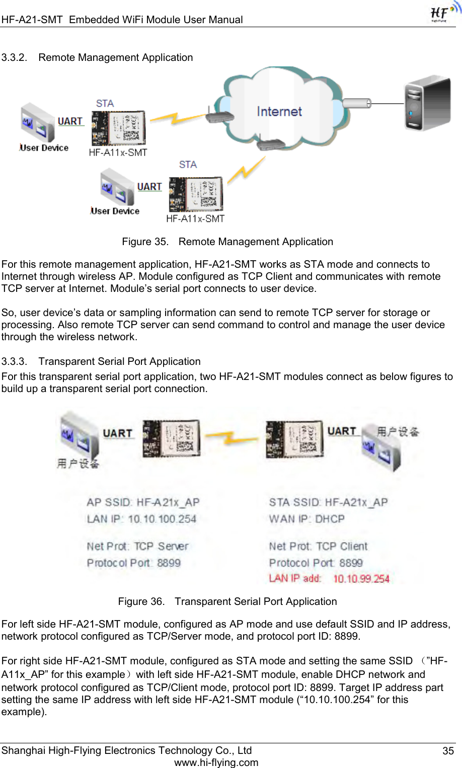
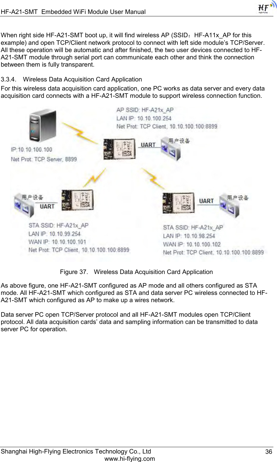
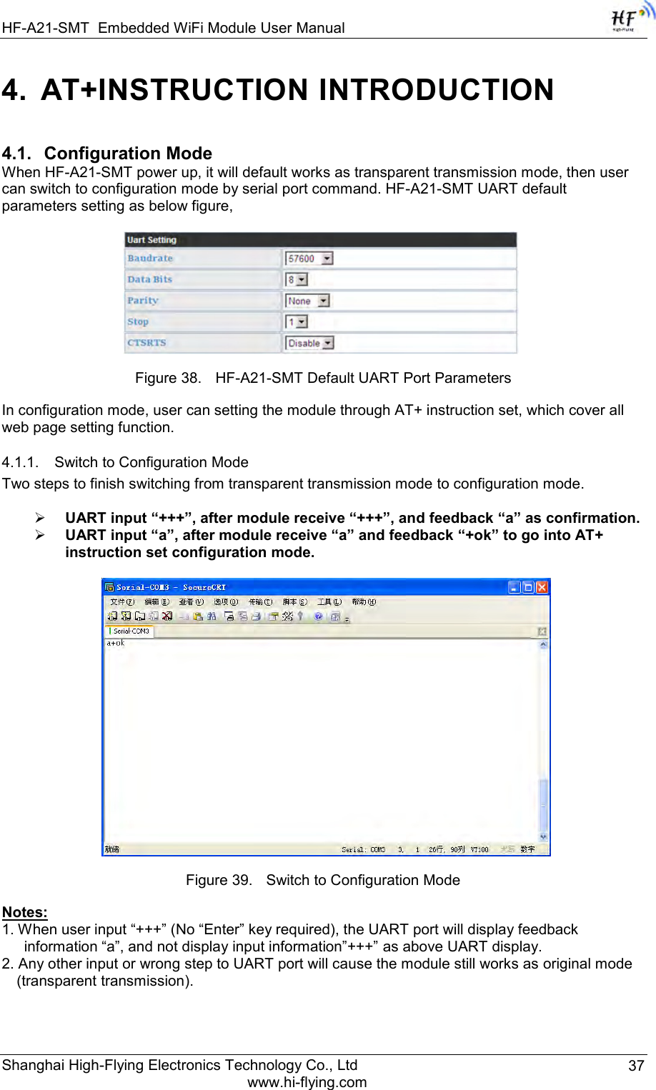
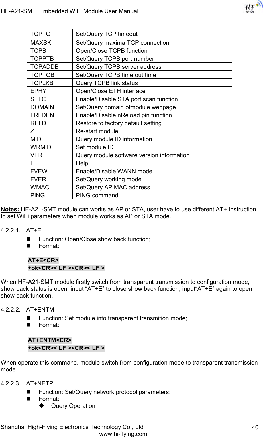
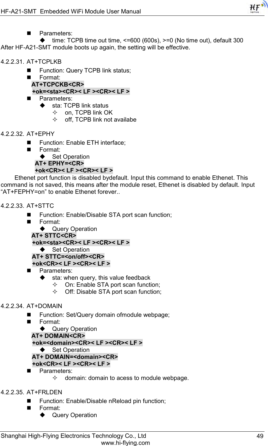
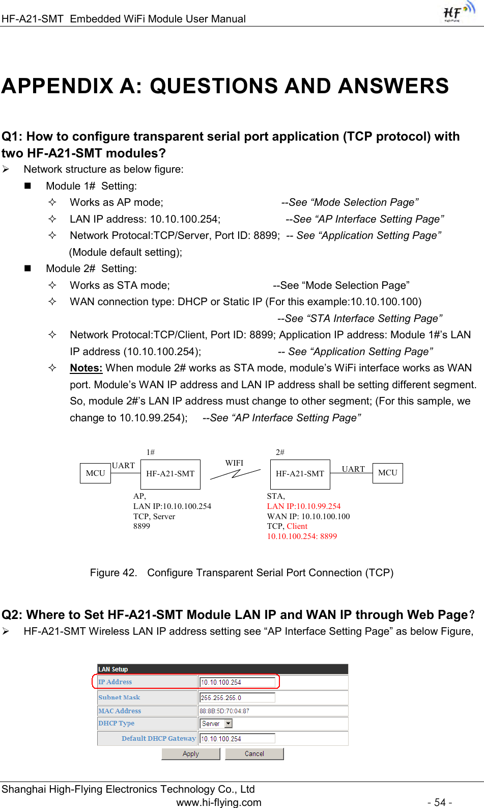
![HF-A21-SMT Embedded WiFi Module User Manual Shanghai High-Flying Electronics Technology Co., Ltd www.hi-flying.com 38 4.2. AT+ Instruction Set Overview User can input AT+ Instruction through hyper terminal or other serial debug terminal, also can program the AT+ Instruction to script. User can also input “AT+H” to list all AT+ Instruction and description to start. Figure 40. ”AT+H” Instruction for Help 4.2.1. Instruction Syntax Format AT+Instruction protocol is based on the instruction of ASCII command style, the description of syntax format as follow. Format Description < >: Means the parts must be included [ ]: Means the optional part Command Message AT+<CMD>[op][para-1,para-2,para-3,para-4…]<CR> AT+: Prefix of command message; CMD: Command string; [op]: Symbol of command operator, “=” : The command requires parameters input; “NULL”: Query the current command parameters setting; [para-n]: Parameters input for setting if required; <CR>:”Enter” Key, it‟s 0x0a or 0x0d in ASCII; Notes: When input AT+Instruction, “AT+<CMD>” character will display capital letter automatic and other parts will not change as you input. Response Message +<RSP>[op] [para-1,para-2,para-3,para-4…]<CR><LF><CR><LF> +: Prefix of response message; RSP: Response string;](https://usermanual.wiki/High-Flying-Electronics-Technology/HF-A21-SMT/User-Guide-2709965-Page-38.png)
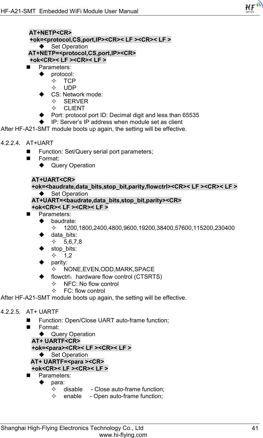
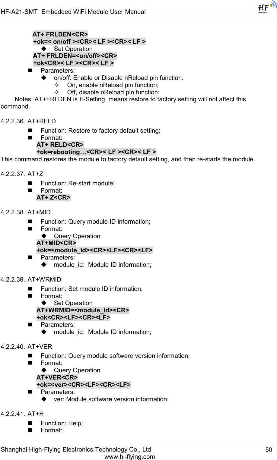
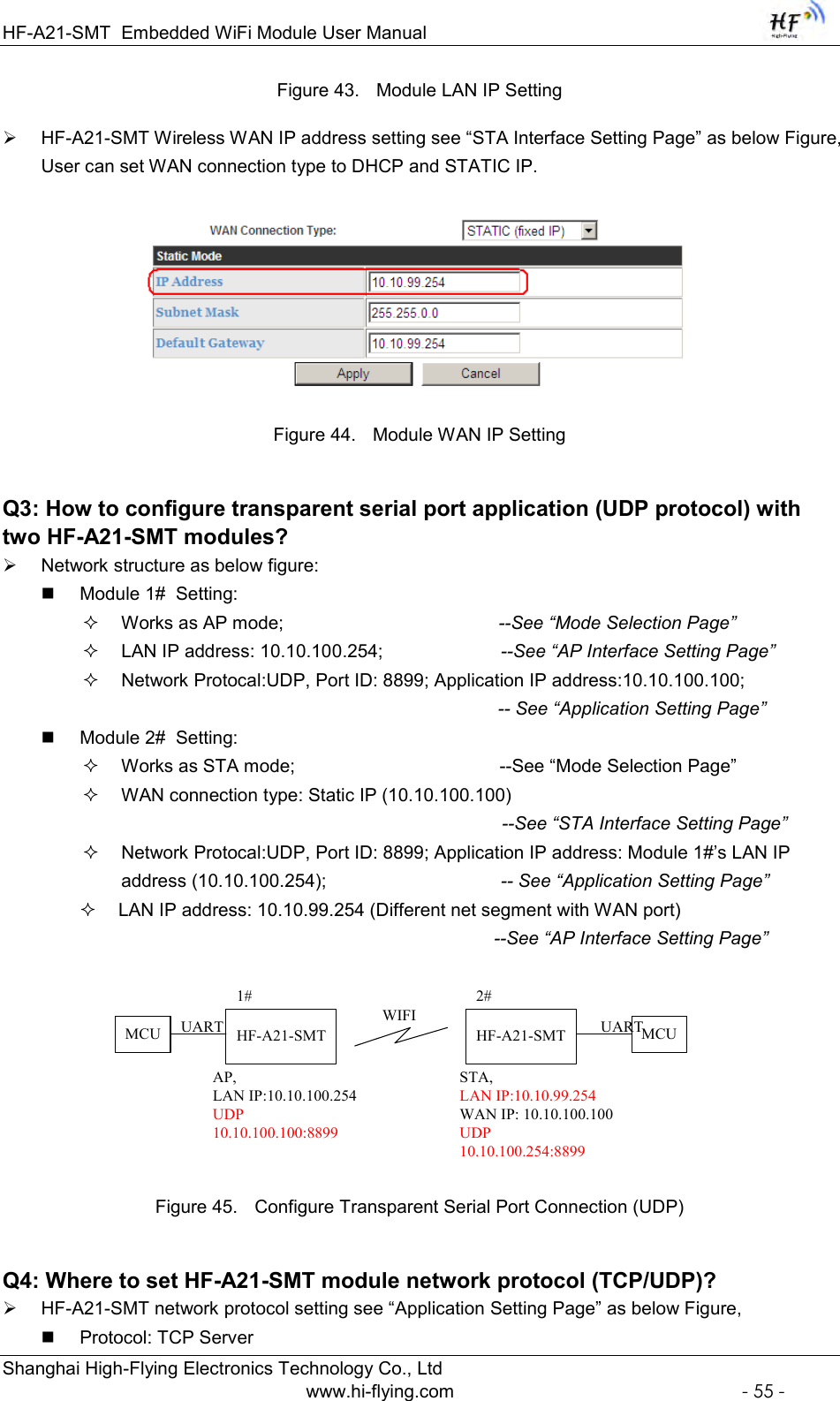
![HF-A21-SMT Embedded WiFi Module User Manual Shanghai High-Flying Electronics Technology Co., Ltd www.hi-flying.com 39 “ok” : Success “ERR”: Failure [op] : = [para-n]: Parameters if query command or Error code when error happened; <CR>: ASCII 0x0d; <LF>: ASCIII 0x0a; Error Code Table 5 Error Code DescribtionHF-A21-SMT Web Access Default Setting Error Code Description -1 Invalid Command Format -2 Invalid Command -3 Invalid Operation Symbol -4 Invalid Parameter -5 Operation Not Permitted 4.2.2. AT+ Instruction Set Table 6 AT+ Instruction Set List Instruction Description <null> NULL E Open/Close show back function ENTM Set module into transparent transmition mode NETP Set/Query network protocol parameters UART Set/Query serial port parameters UARTF Open/Close UART auto-frame function UARTFT Set/Query UART auto-frame trigger time UARTFL Set/Query UART auto-frame trigger length TMODE Set/Query data transmition mode (transparent transmition) WMODE Set/Query WIFI work mode (AP or STA) WSKEY Set/Query WIFI security parameters as STA WSSSID Set/Query WIFI target AP SSID parameters as STA WSLK Query WiFi link status as STA WEBU Set/Query WEB page login parameters (User Name and Password) WAP Set/Query WIFI parameters as AP WAKEY Set/Query WIFI security parameters as AP HIDESSID Set/Query hide AP‟s SSID MSLP Set modules into power save mode.(Turn OFF WiFi) WSCAN Seek AP when module works as STA mode TCPLK Query if TCP link already build-up TCPDIS Open/Cose TCP (Only TCP Client available) WANN Set/Query WAN setting, only effective as STA mode LANN Set/Query LAN setting, only effective as AP mode DHCPDEN Enable/Disable LAN DHCP server function DHCPGW Set/Query DHCP gateway address](https://usermanual.wiki/High-Flying-Electronics-Technology/HF-A21-SMT/User-Guide-2709965-Page-39.png)