High Flying Electronics Technology HF-DTU-H100 HF-DTU-H100 User Manual GPON SFU System Design
High-Flying Electronics Technology Co., Ltd. HF-DTU-H100 GPON SFU System Design
UserManual.wiki
>
High Flying Electronics Technology
>
HF DTU H100 User Manual
User Manual
Navigation menu
Upload a User Manual
Namespaces
Wiki Guide
HTML
PDF
Info
Views
User Manual
Discussion / Help
Navigation
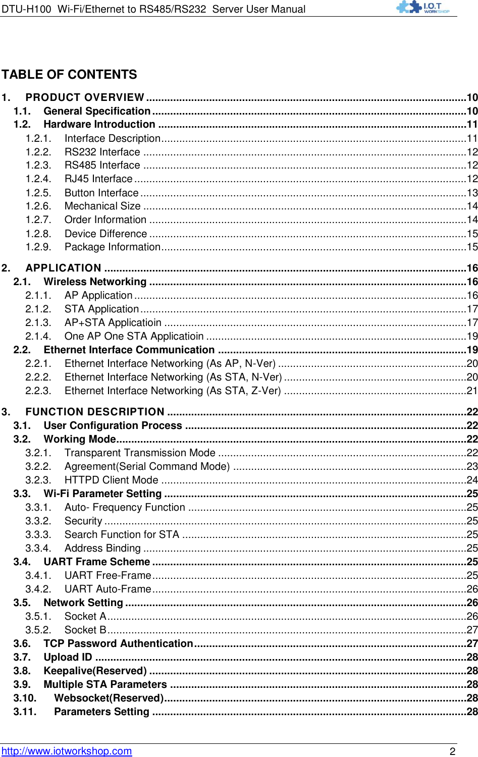
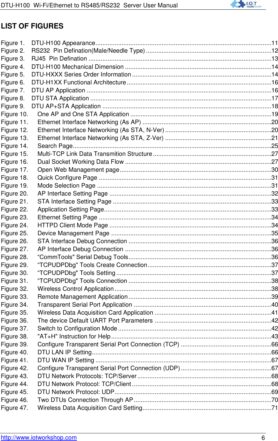
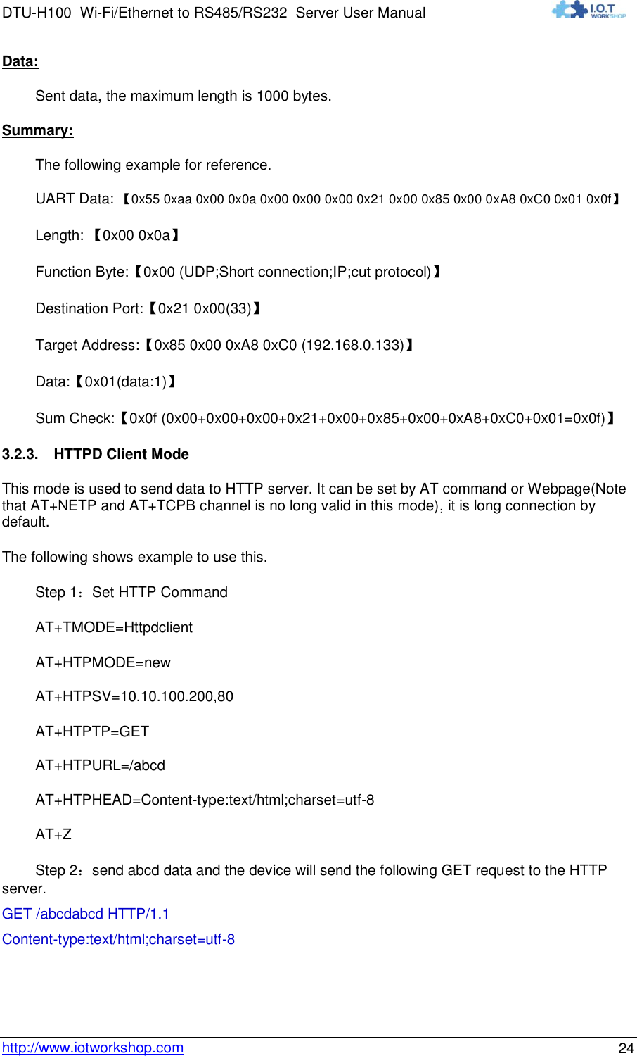
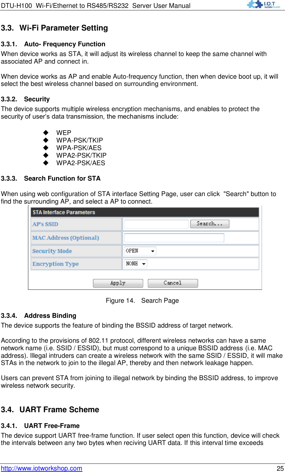
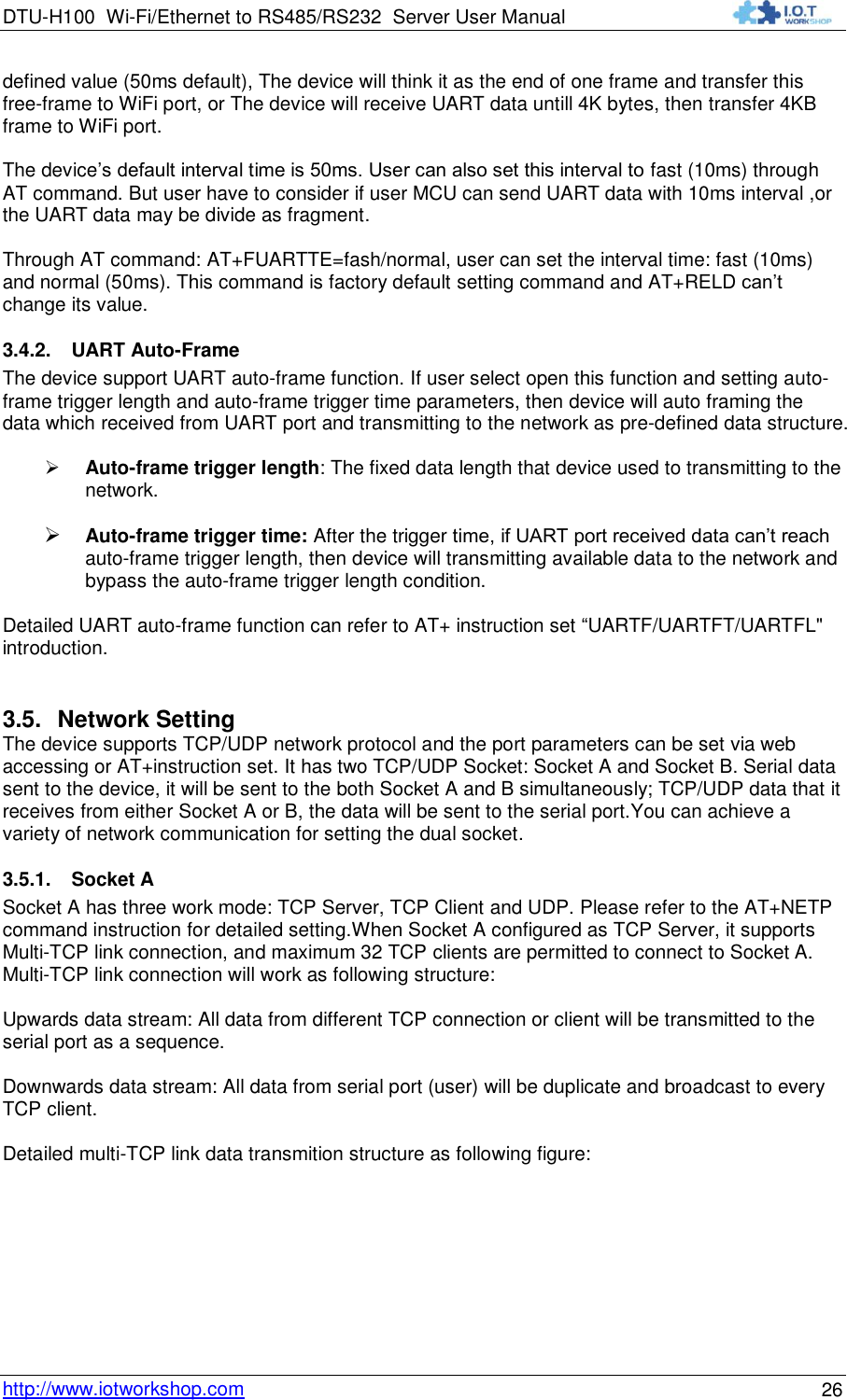
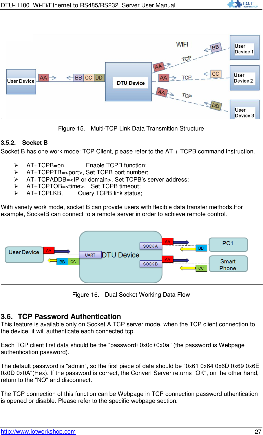
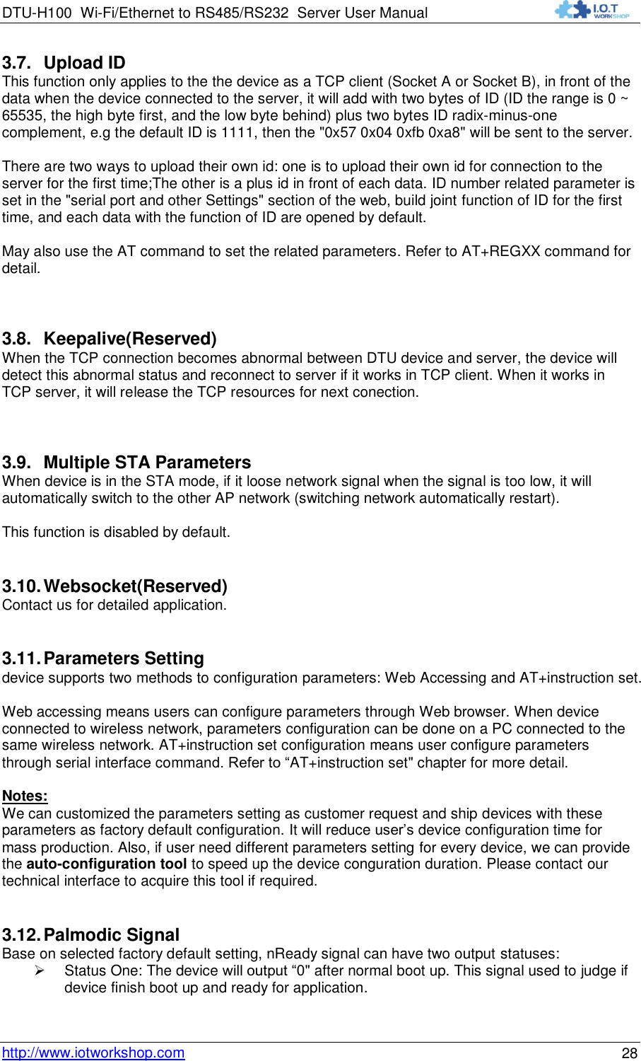
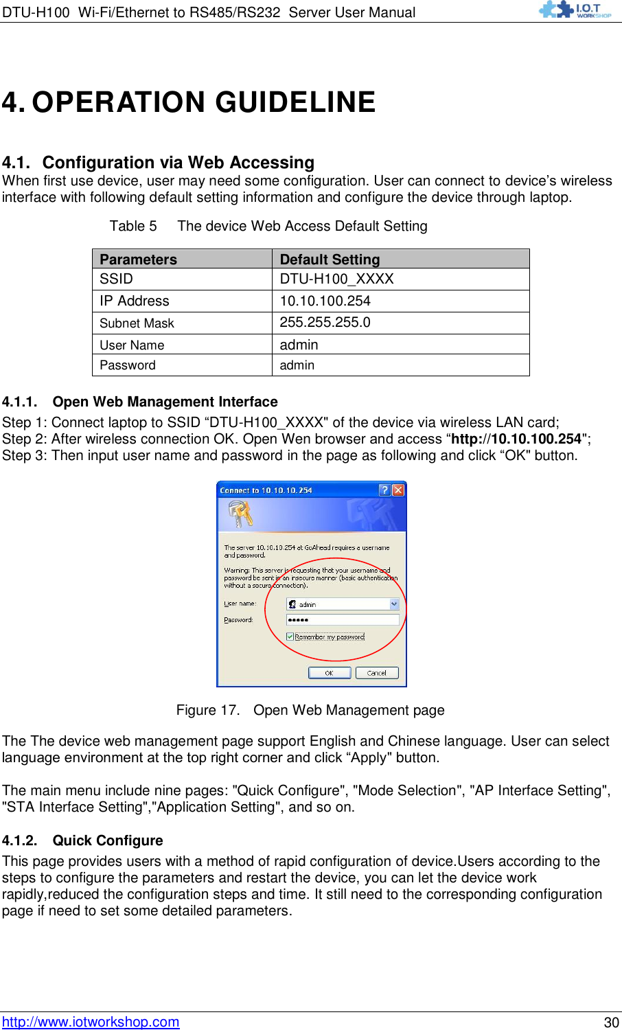
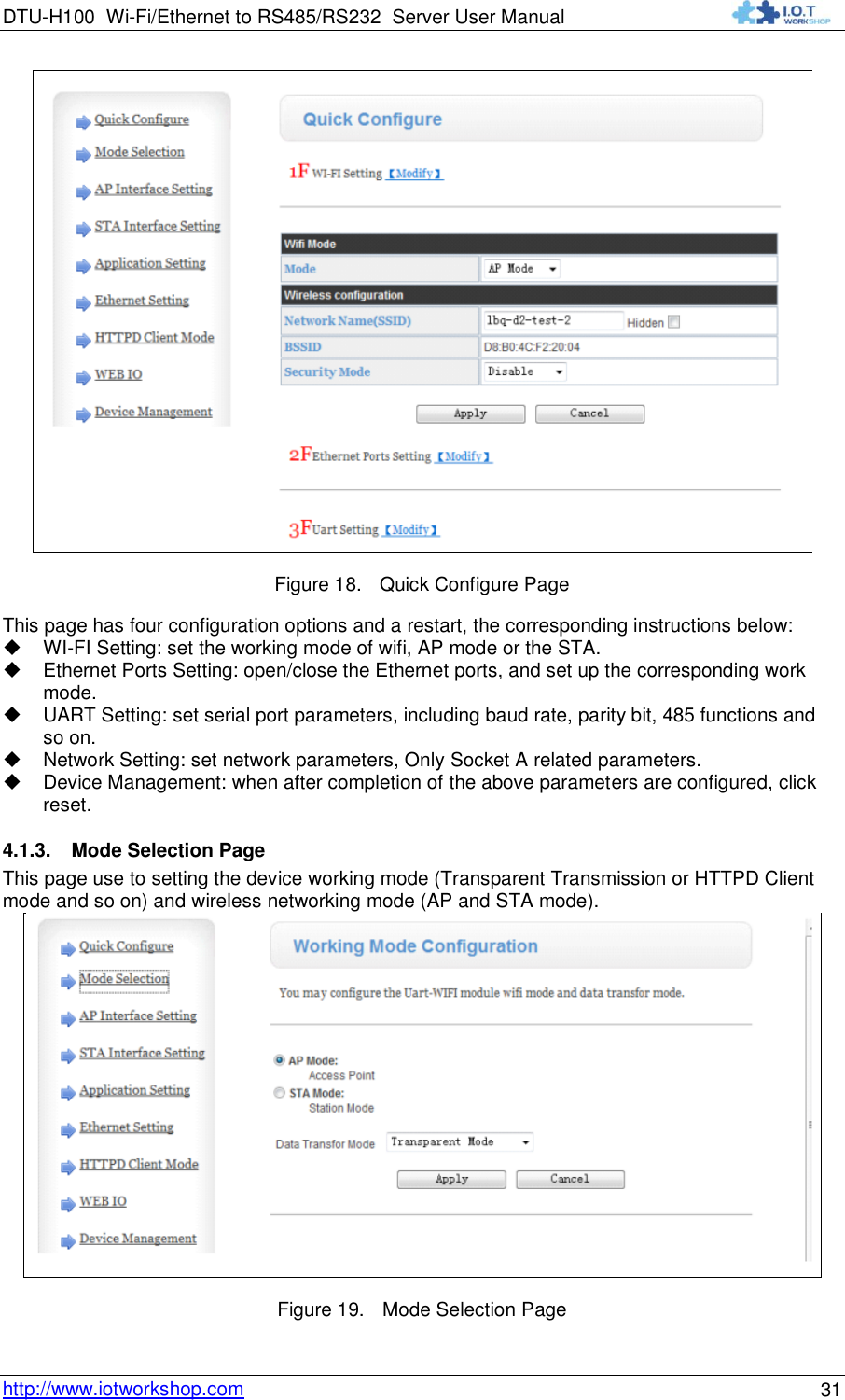
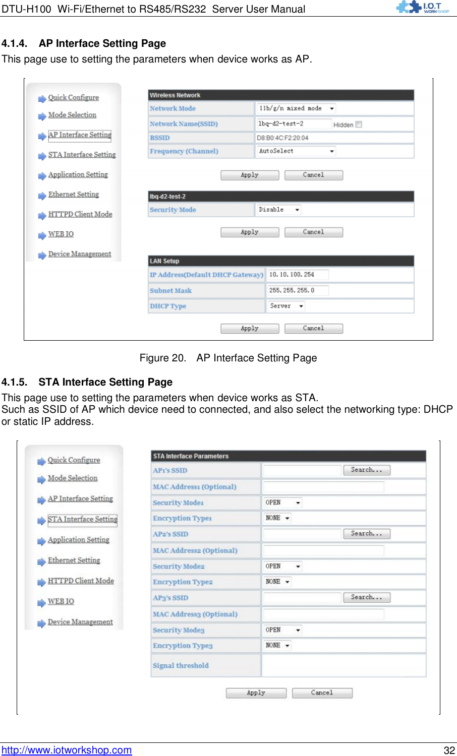

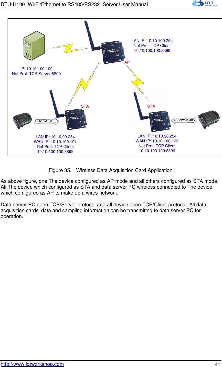
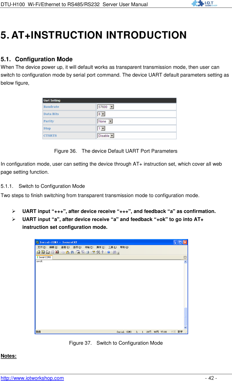
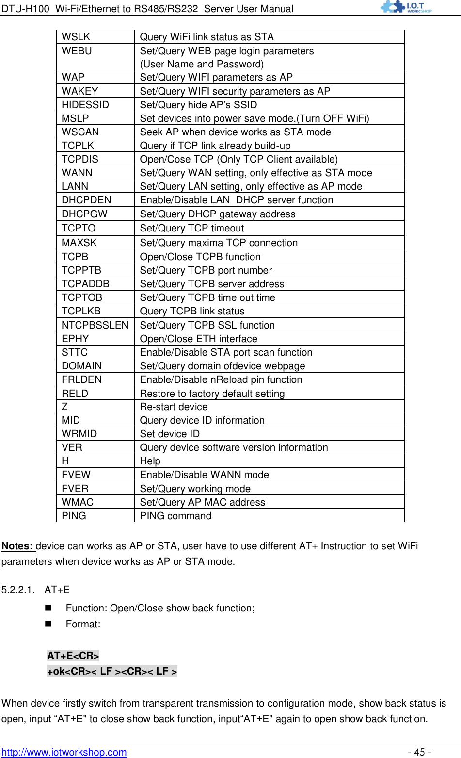
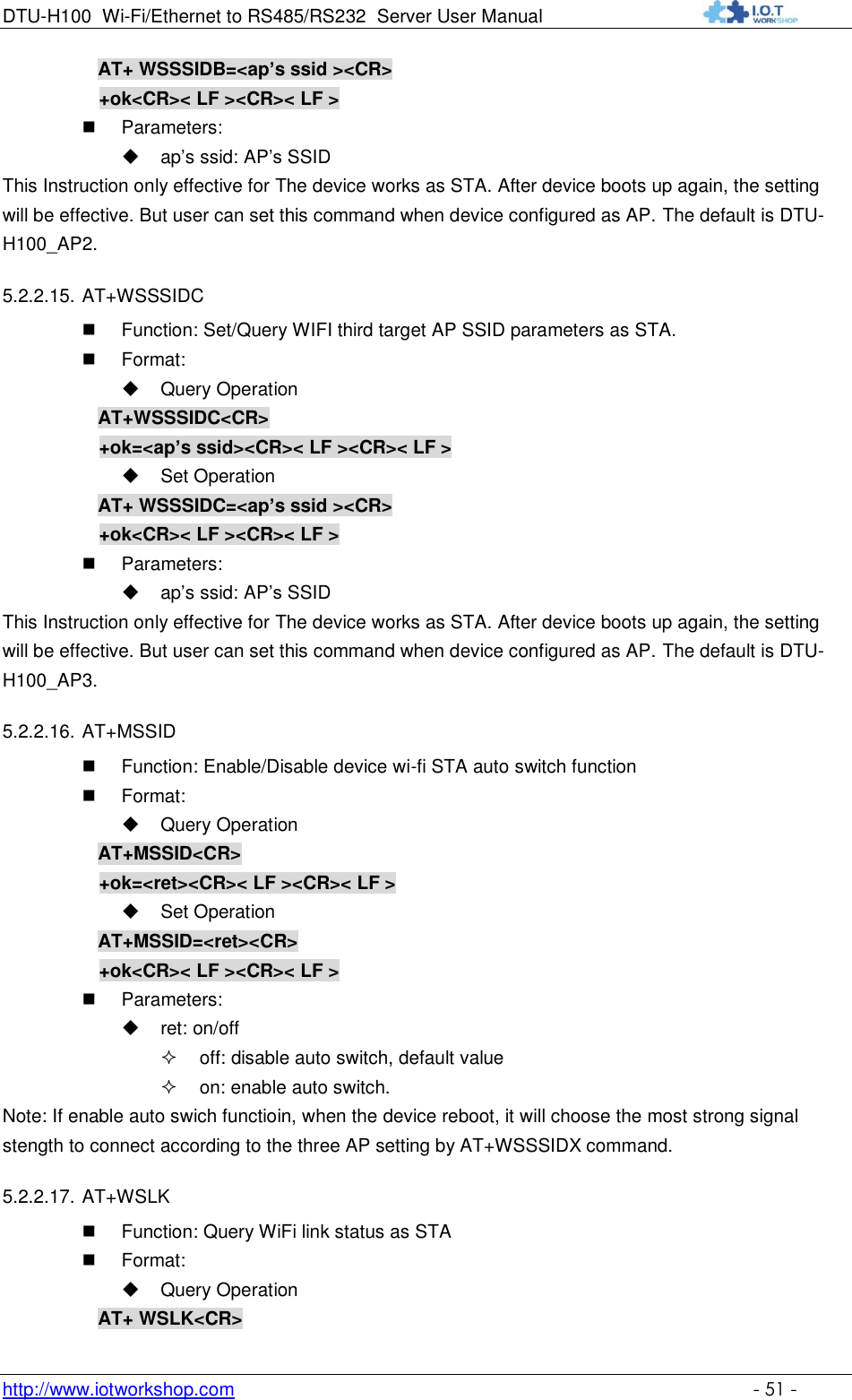
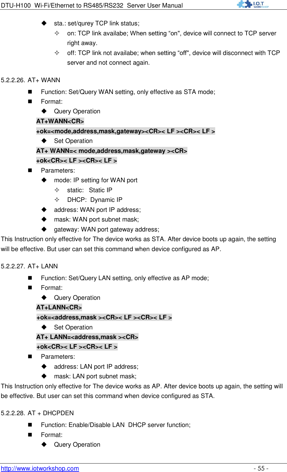
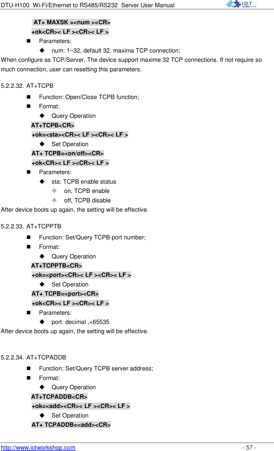
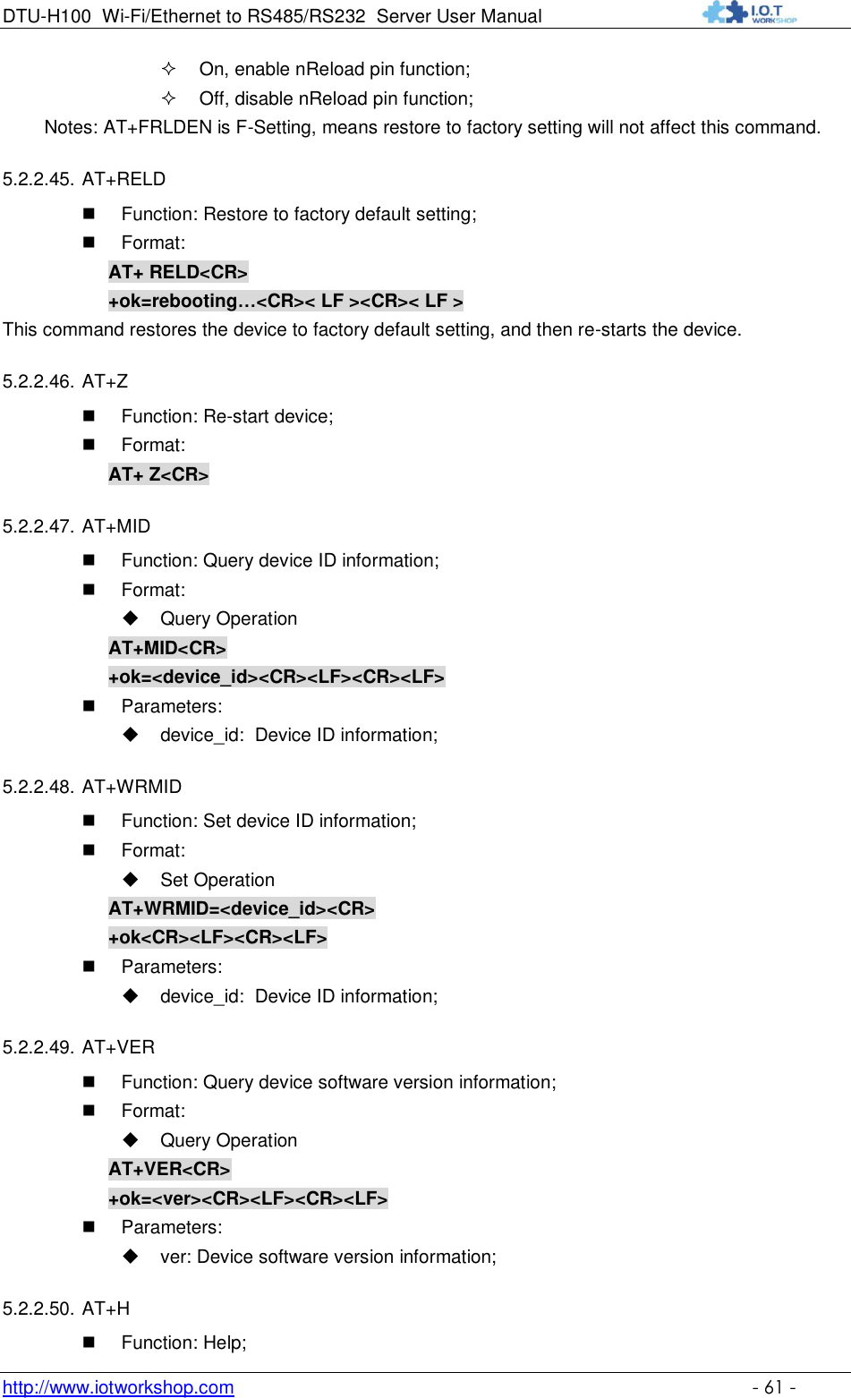
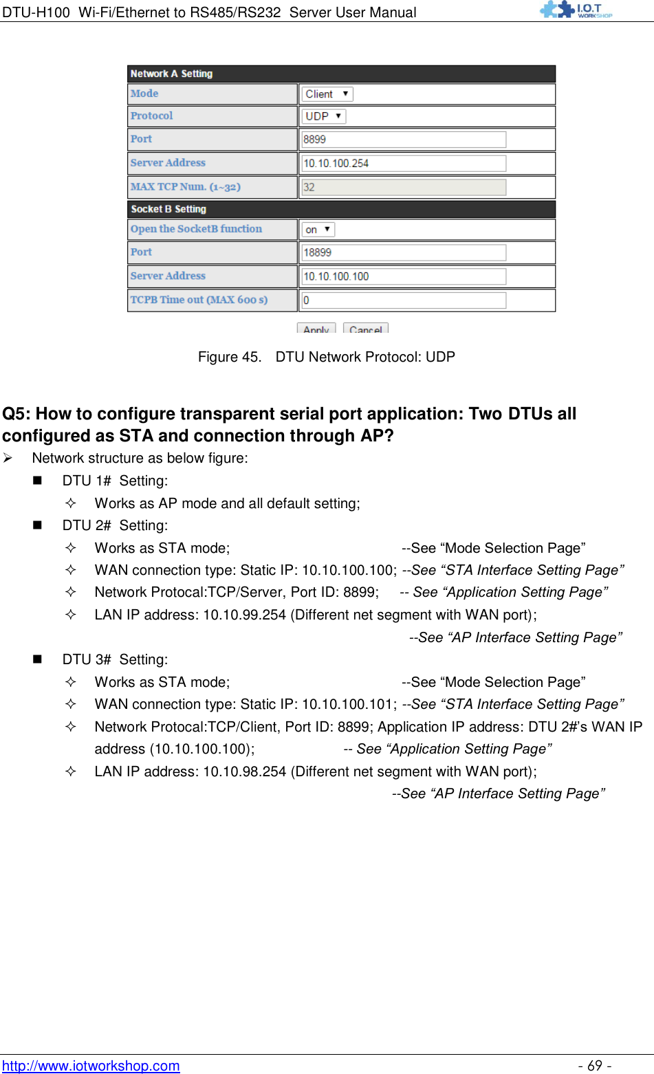
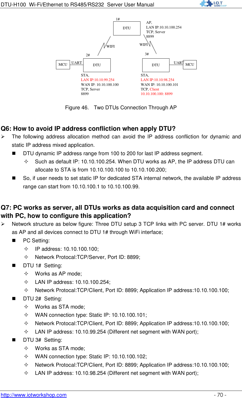
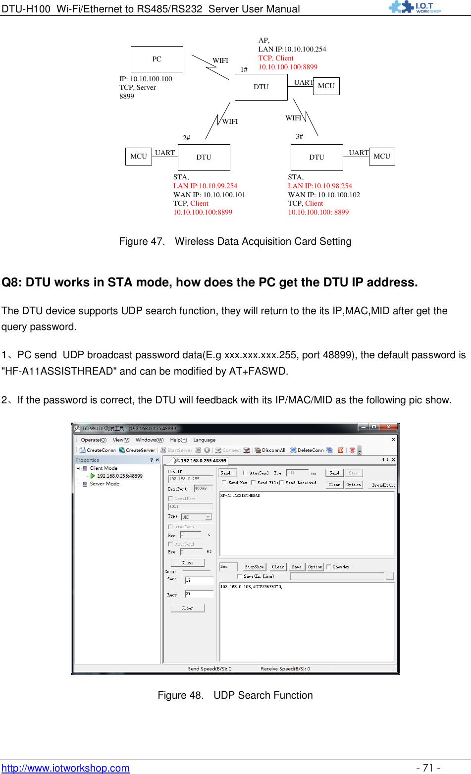
![DTU-H100 Wi-Fi/Ethernet to RS485/RS232 Server User Manual http://www.iotworkshop.com - 43 - 1. When user input “+++" (No “Enter" key required), the UART port will display feedback information “a", and not display input information"+++" as above UART display. 2. Any other input or wrong step to UART port will cause the device still works as original mode (transparent transmission). 5.2. AT+ Instruction Set Overview User can input AT+ Instruction through hyper terminal or other serial debug terminal, also can program the AT+ Instruction to script. User can also input “AT+H" to list all AT+ Instruction and description to start. Figure 38. "AT+H" Instruction for Help 5.2.1. Instruction Syntax Format AT+Instruction protocol is based on the instruction of ASCII command style, the description of syntax format as follow. Format Description < >: Means the parts must be included [ ]: Means the optional part Command Message AT+<CMD>[op][para-1,para-2,para-3,para-4…]<CR> AT+: Prefix of command message; CMD: Command string; [op]: Symbol of command operator, “=" : The command requires parameters input;](https://usermanual.wiki/High-Flying-Electronics-Technology/HF-DTU-H100/User-Guide-3050761-Page-43.png)
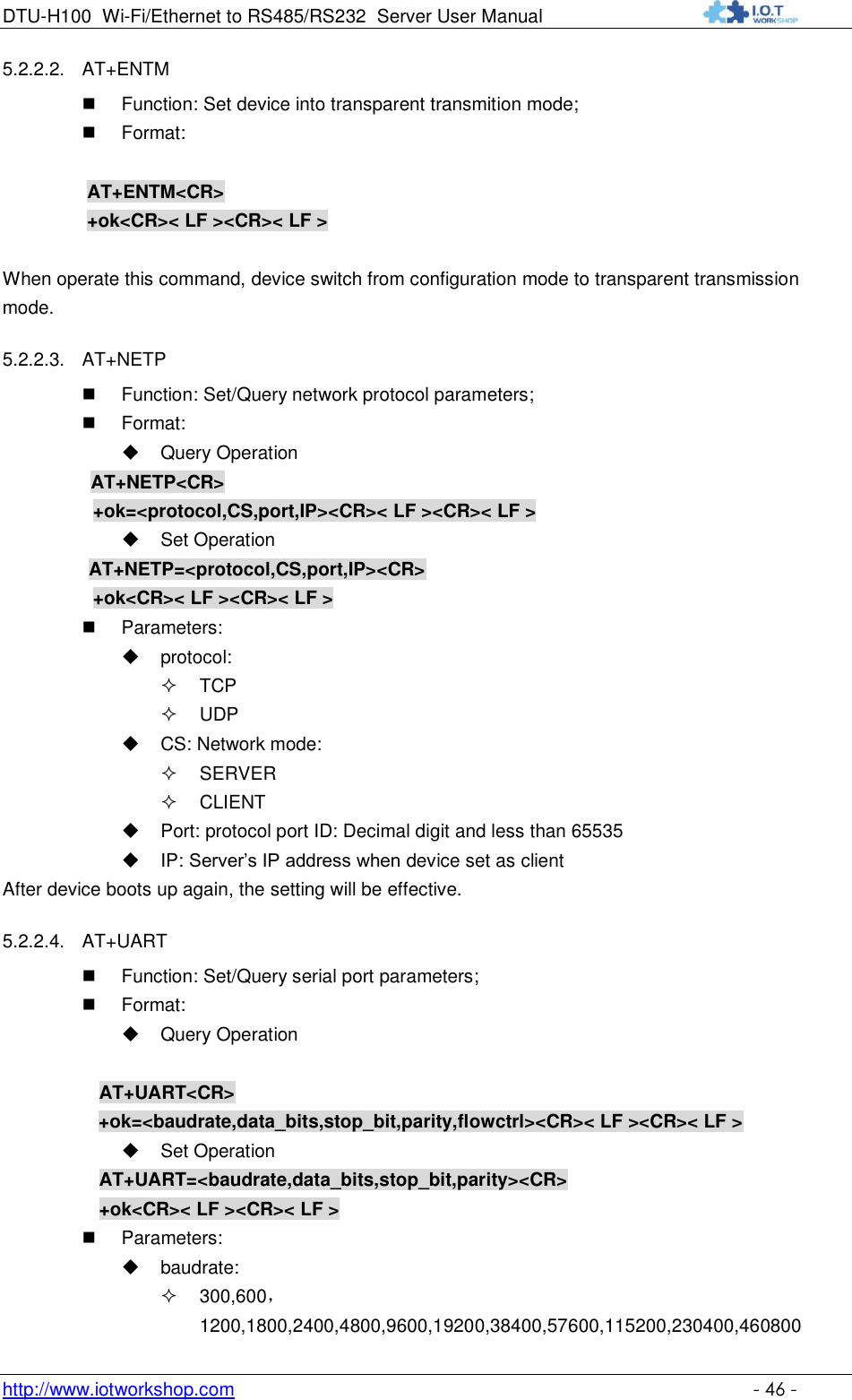
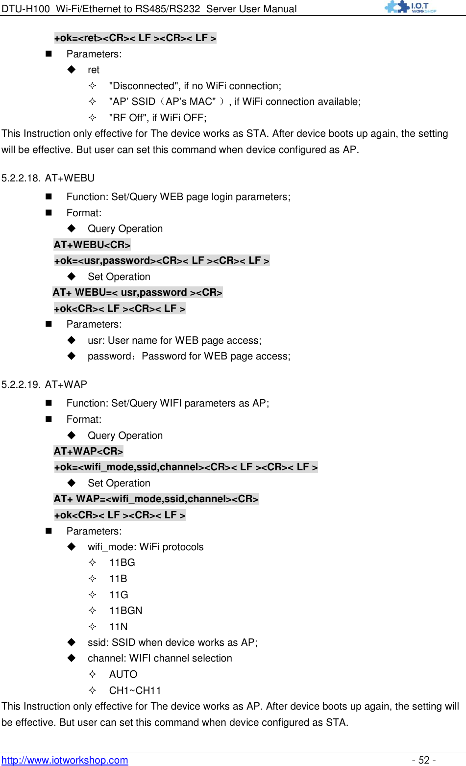
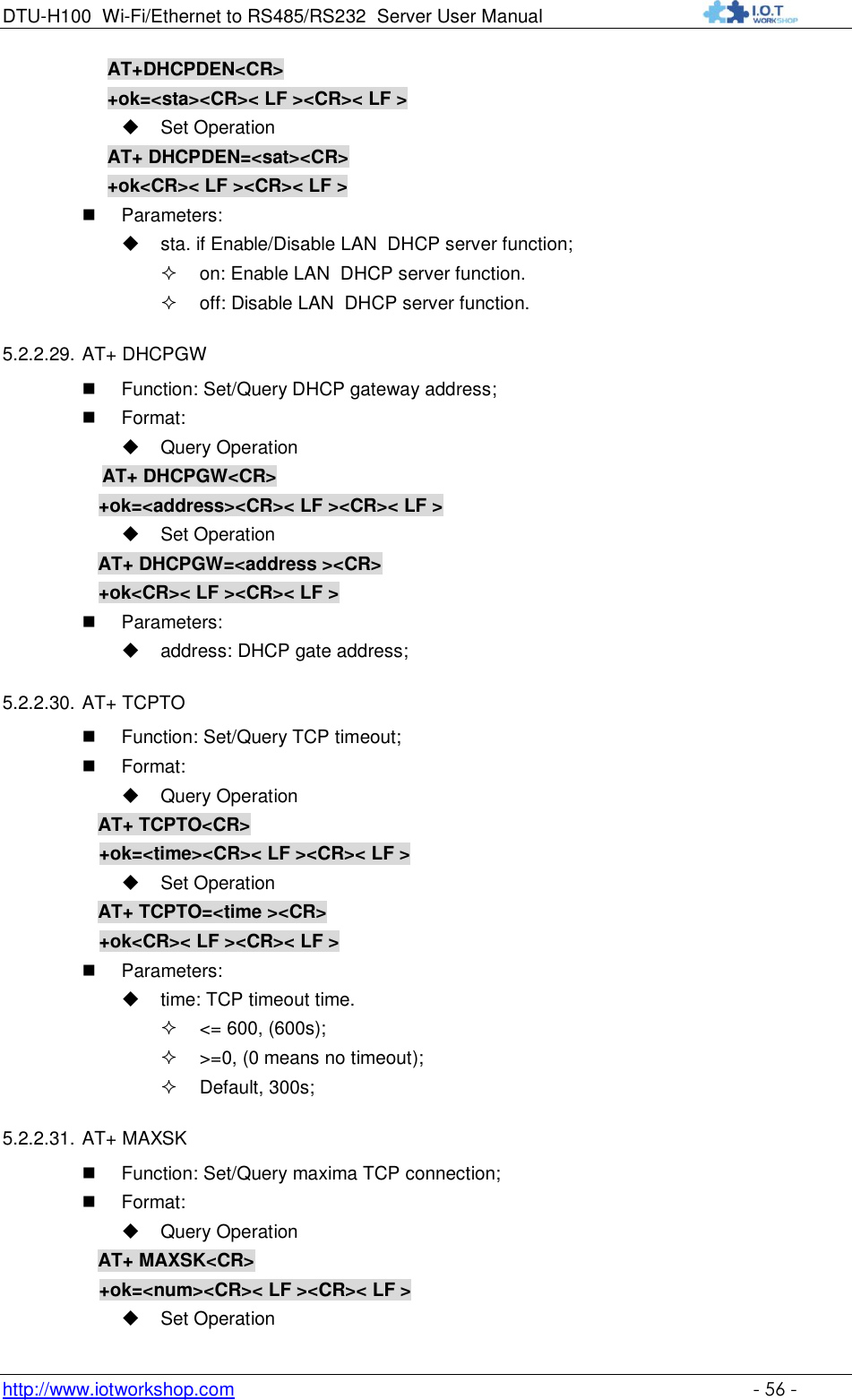
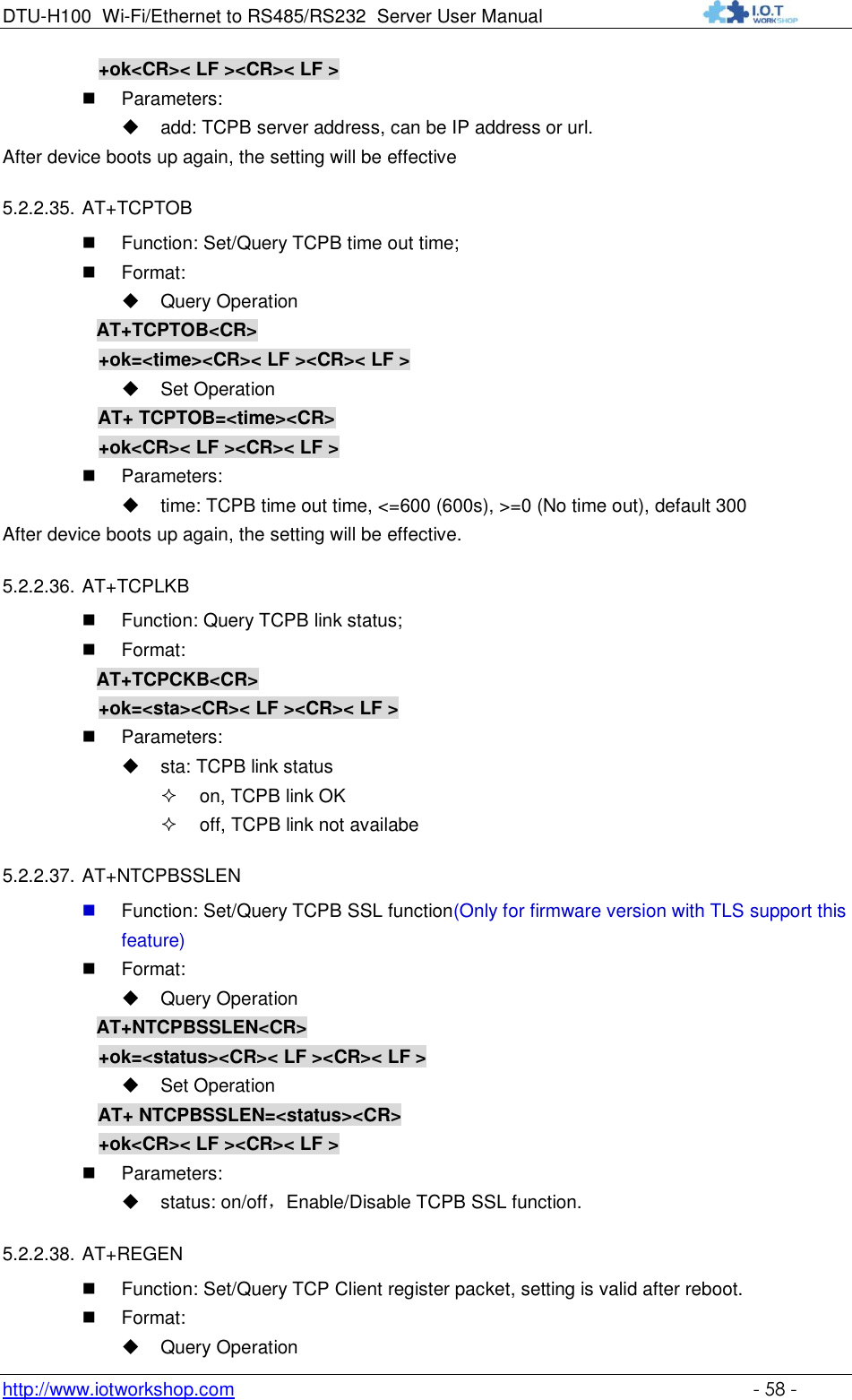
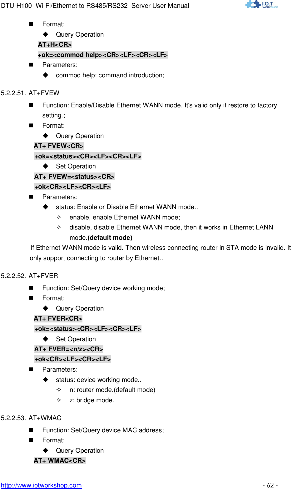
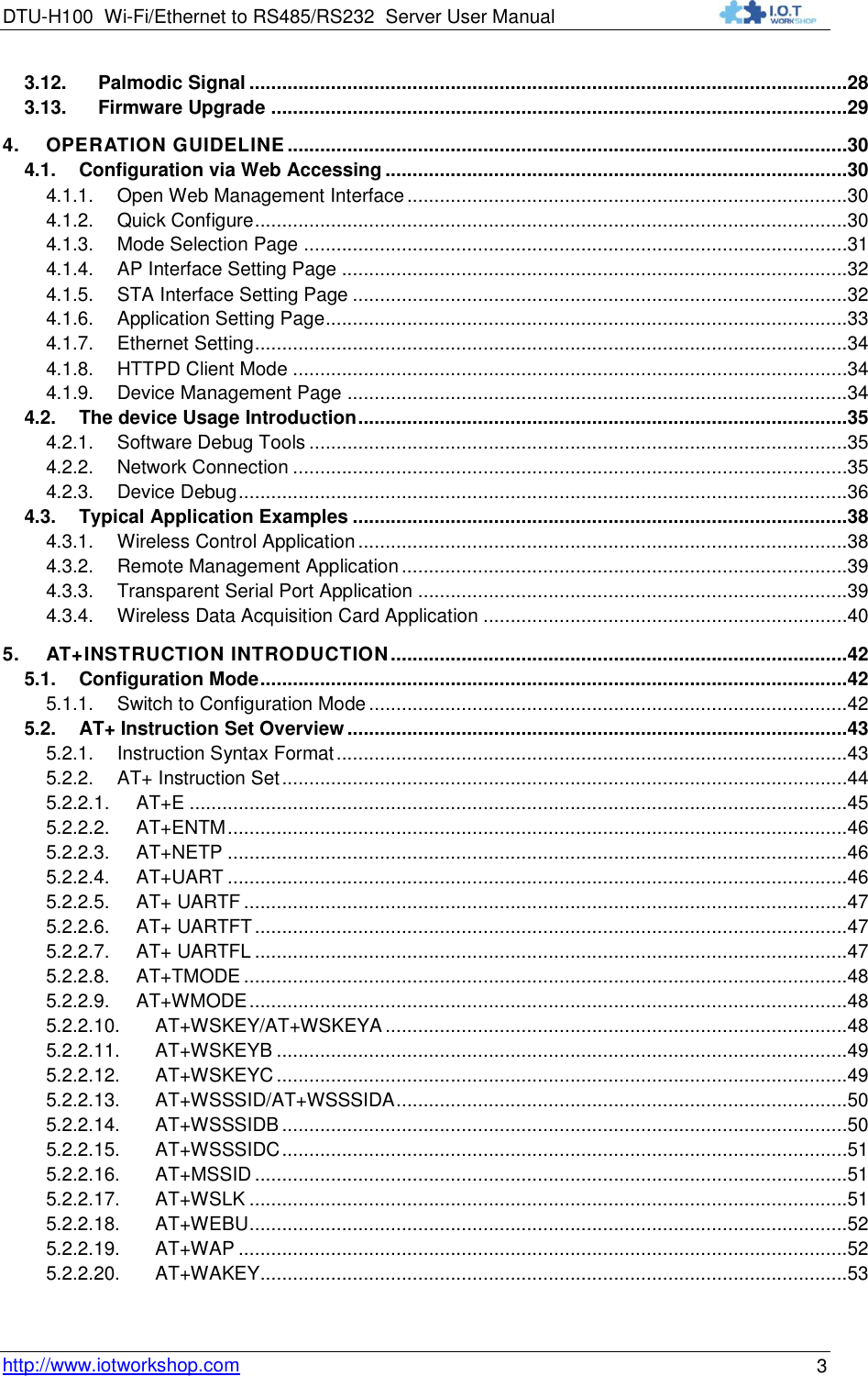
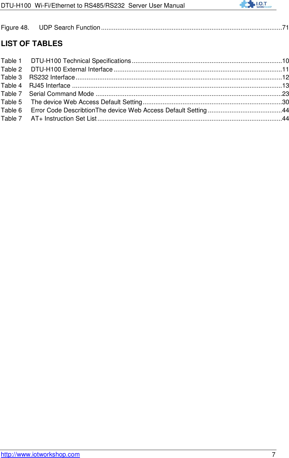
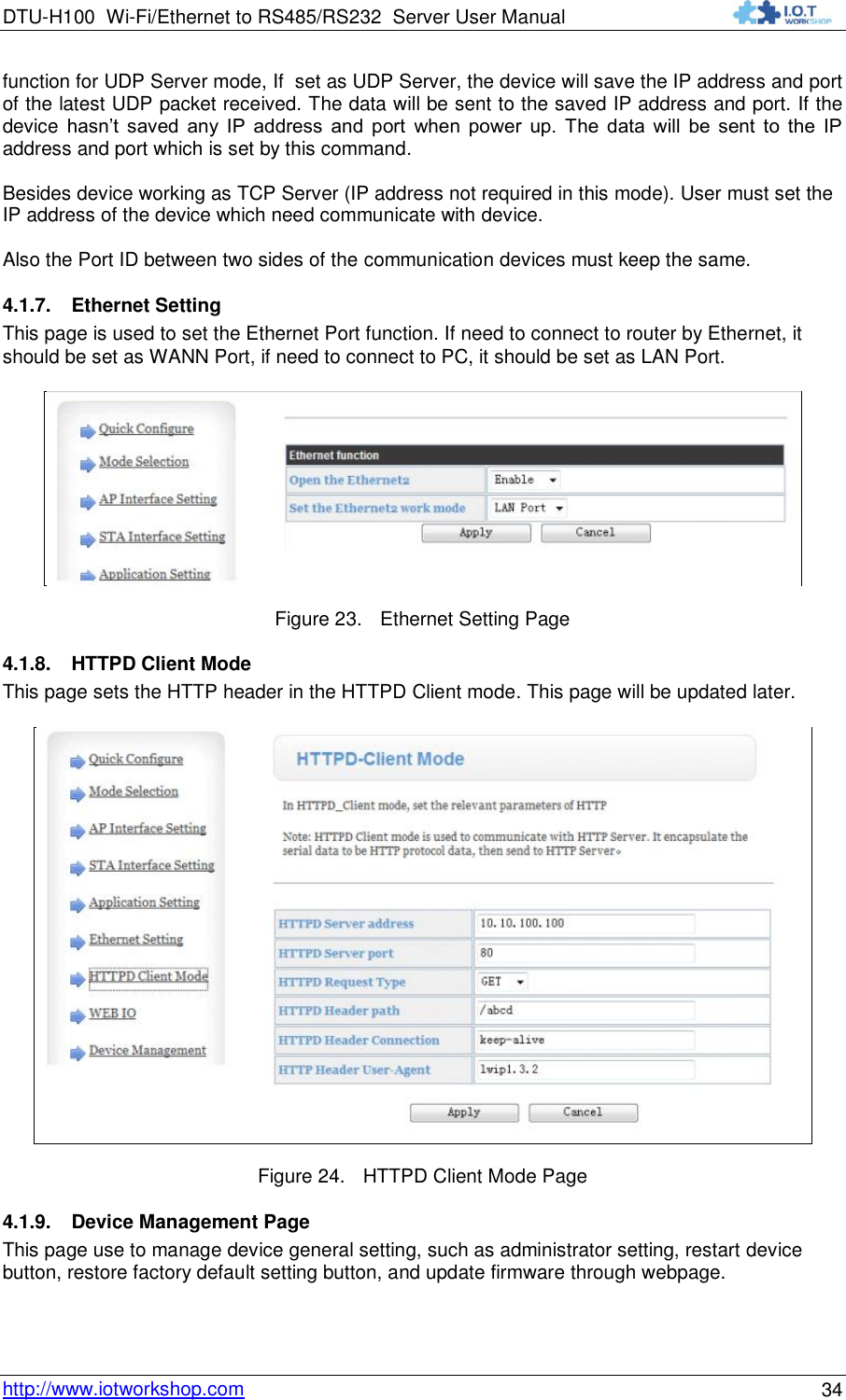
![DTU-H100 Wi-Fi/Ethernet to RS485/RS232 Server User Manual http://www.iotworkshop.com - 44 - “NULL": Query the current command parameters setting; [para-n]: Parameters input for setting if required; <CR>:"Enter" Key, it‟s 0x0a or 0x0d in ASCII; Notes: When input AT+Instruction, “AT+<CMD>" character will display capital letter automatic and other parts will not change as you input. Response Message +<RSP>[op] [para-1,para-2,para-3,para-4…]<CR><LF><CR><LF> +: Prefix of response message; RSP: Response string; “ok" : Success “ERR": Failure [op] : = [para-n]: Parameters if query command or Error code when error happened; <CR>: ASCII 0x0d; <LF>: ASCIII 0x0a; Error Code Table 6 Error Code DescribtionThe device Web Access Default Setting Error Code Description -1 Invalid Command Format -2 Invalid Command -3 Invalid Operation Symbol -4 Invalid Parameter -5 Operation Not Permitted 5.2.2. AT+ Instruction Set Table 7 AT+ Instruction Set List Instruction Description <null> NULL E Open/Close show back function ENTM Set device into transparent transmition mode NETP Set/Query network protocol parameters UART Set/Query serial port parameters UARTF Open/Close UART auto-frame function UARTFT Set/Query UART auto-frame trigger time UARTFL Set/Query UART auto-frame trigger length TMODE Set/Query data transmition mode (transparent transmition) WMODE Set/Query WIFI work mode (AP or STA) WSKEY Set/Query WIFI security parameters as STA WSSSID Set/Query WIFI target AP SSID parameters as STA](https://usermanual.wiki/High-Flying-Electronics-Technology/HF-DTU-H100/User-Guide-3050761-Page-44.png)