High Flying Electronics Technology HF-LPB Embedded WIFI module User Manual AZY HF LPB Rev1
High-Flying Electronics Technology Co.,Ltd Embedded WIFI module AZY HF LPB Rev1
UserManual.wiki
>
High Flying Electronics Technology
>
HF LPB User Manual
AZY-HF-LPB_User Manual Rev1
Navigation menu
Upload a User Manual
Namespaces
Wiki Guide
HTML
PDF
Info
Views
User Manual
Discussion / Help
Navigation
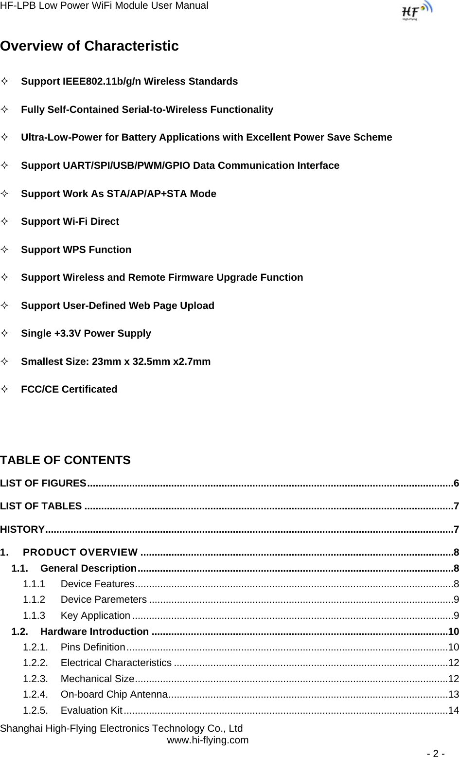
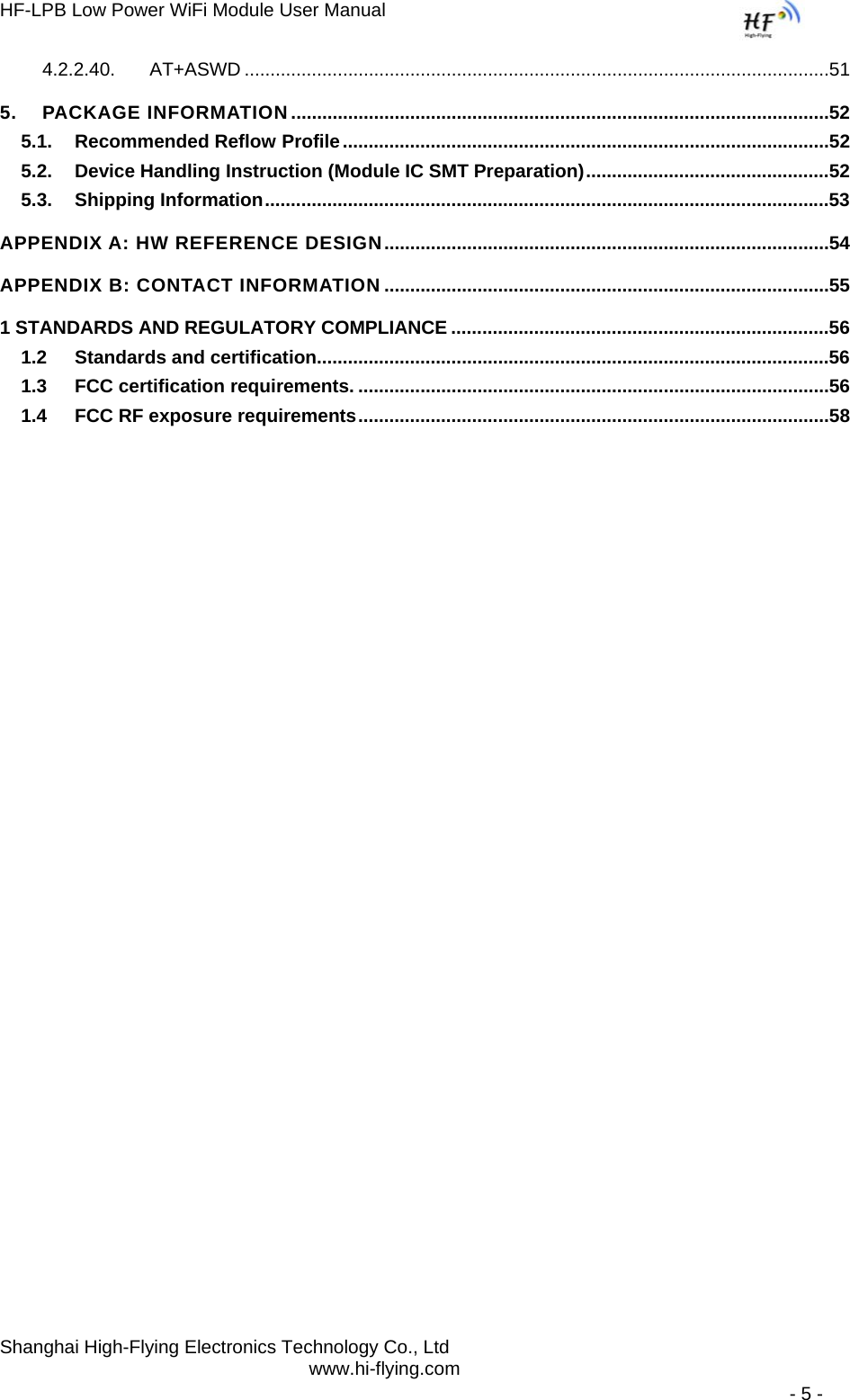
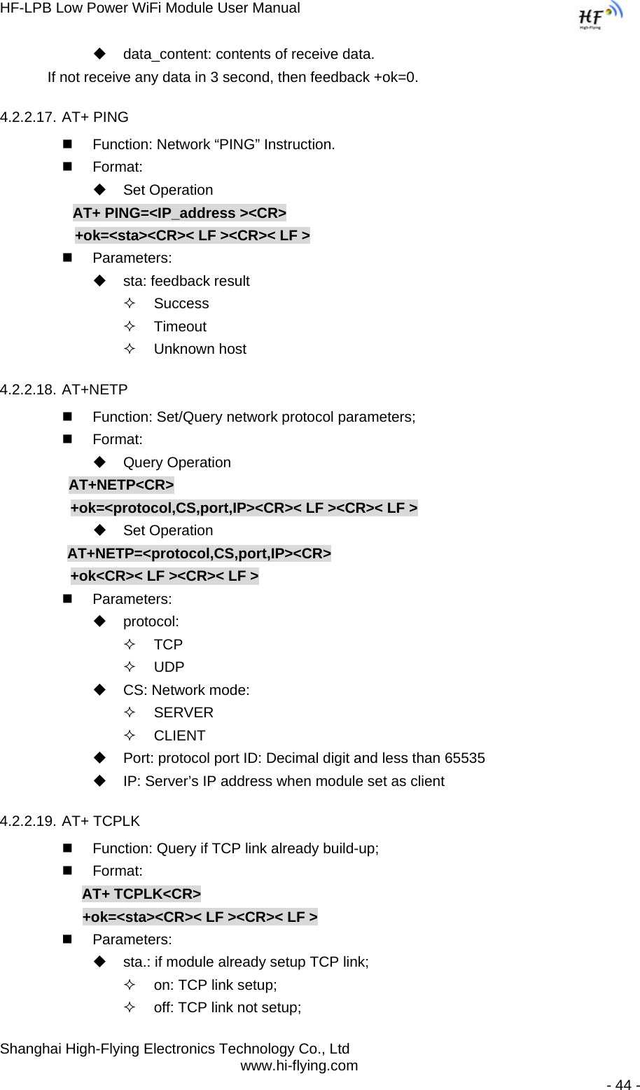
![HF-LPB Low Power WiFi Module User Manual Shanghai High-Flying Electronics Technology Co., Ltd www.hi-flying.com - 9 - 1.1.2 Device Paremeters Table 1 HF-LPB Module Technical Specifications Class Item Parameters Wireless Parameters Certification FCC/CE Wireless standard 802.11 b/g/n US Frequency range 2.412GHz-2.462GHz EU Frequency range 2.412GHz-2.472GHz Transmit Power 802.11b: +18dBm (Max.) 802.11g: +14dBm (Max.) 802.11n: +11dBm (Max.) Configurable Receiver Sensitivity 802.11b: -93 dBm (@11Mbps ,CCK) 802.11g: -85 dBm (@54Mbps, OFDM) 802.11n: -82 dBm (@HT20, MCS7) Antenna Option Internal:On-board PCB antenna Hardware Parameters Data Interface UART USB, SPI, PWM… Others: GPIO, ADC/DAC, RTC… Operating Voltage 3.1~3.6V Operating Current Peak [Continuous TX]: ~200mA Normal [WiFi ON/OFF, DTIM=100ms]: Average. ~5mA, Peak: 200mA Deep Sleep: [WiFi OFF]: ~2mA Standby [WiFi Shutdown]: <2uA Operating Temp. -40℃- 85℃ Storage Temp. -45℃- 125℃ Dimensions and Size 23mm×32.5mm×2.7mm Software Parameters Network Type STA /AP/STA+AP/Wi-Fi Direct Security Mechanisms WEP/WPA-PSK/WPA2-PSK/WPS Encryption WEP64/WEP128/TKIP/AES Update Firmware Local Wireless, Remote Customization Web Page Upgrade Support SDK for application develop Serial command AT+instruction set Network Protocol IPv4, IPv6,TCP/UDP/FTP/HTTP User Configuration AT+instruction set. Android/ iOS 1.1.3 Key Application z Remote equipment monitoring z Asset tracking and telemetry z Security z Industrial sensors and controls z Home automation z Medical devices](https://usermanual.wiki/High-Flying-Electronics-Technology/HF-LPB/User-Guide-1937575-Page-9.png)
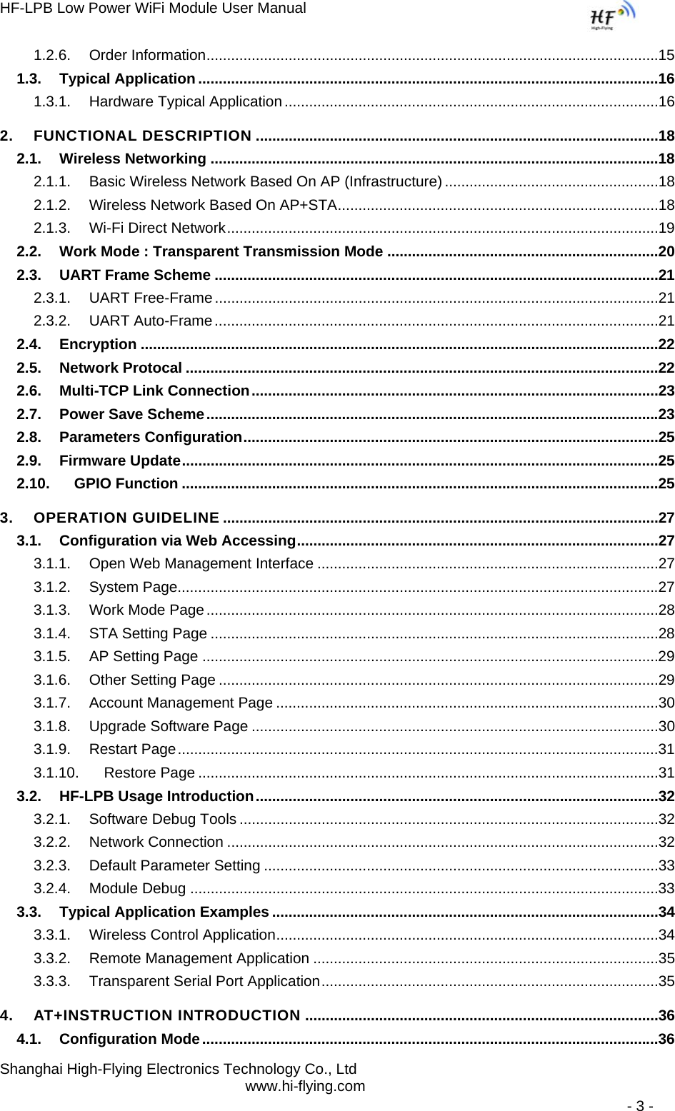
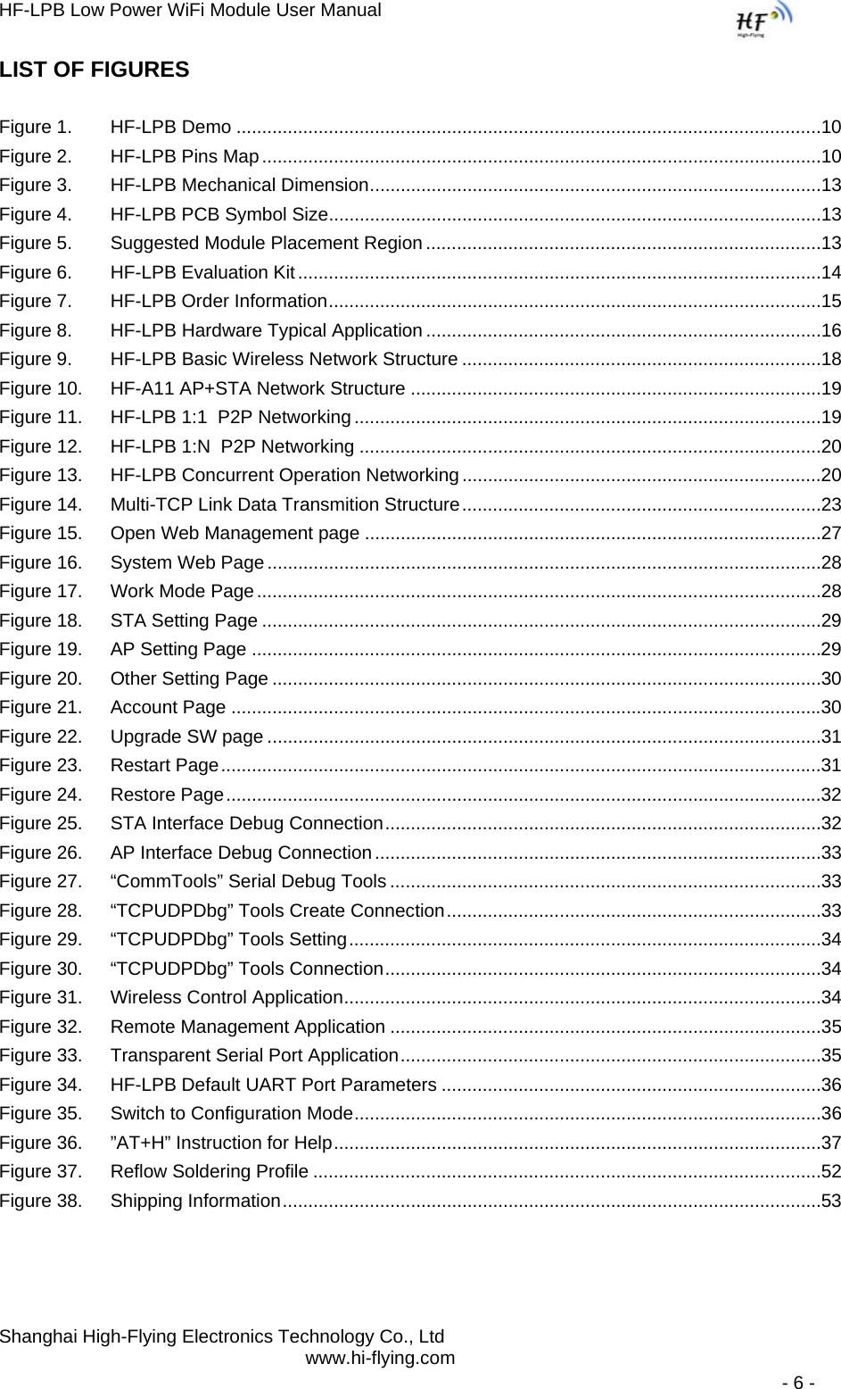
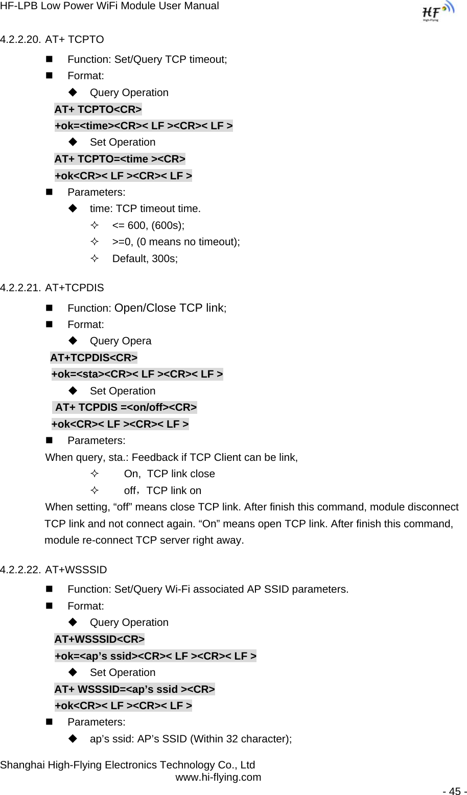
![HF-LPB Low Power WiFi Module User Manual Shanghai High-Flying Electronics Technology Co., Ltd www.hi-flying.com - 37 - 4.2. AT+ Instruction Set Overview User can input AT+ Instruction through hyper terminal or other serial debug terminal, also can program the AT+ Instruction to script. User can also input “AT+H” to list all AT+ Instruction and description to start. Figure 36. ”AT+H” Instruction for Help 4.2.1. Instruction Syntax Format AT+Instruction protocol is based on the instruction of ASCII command style, the description of syntax format as follow. ¾ Format Description < >: Means the parts must be included [ ]: Means the optional part ¾ Command Message AT+<CMD>[op][para-1,para-2,para-3,para-4…]<CR> AT+: Prefix of command message; CMD: Command string; [op]: Symbol of command operator, “=” : The command requires parameters input; “NULL”: Query the current command parameters setting; [para-n]: Parameters input for setting if required; <CR>:”Enter” Key, it’s 0x0a or 0x0d in ASCII;](https://usermanual.wiki/High-Flying-Electronics-Technology/HF-LPB/User-Guide-1937575-Page-37.png)
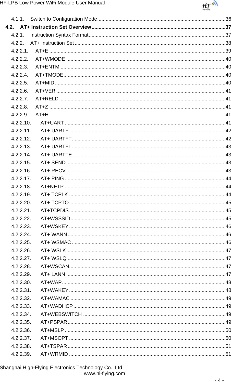
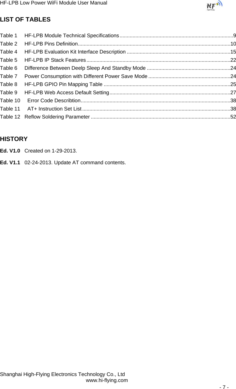
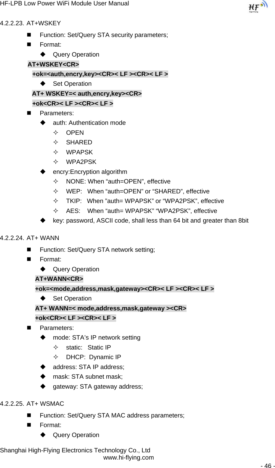
![HF-LPB Low Power WiFi Module User Manual Shanghai High-Flying Electronics Technology Co., Ltd www.hi-flying.com - 38 - Notes: When input AT+Instruction, “AT+<CMD>” character will display capital letter automatic and other parts will not change as you input. ¾ Response Message +<RSP>[op] [para-1,para-2,para-3,para-4…]<CR><LF><CR><LF> +: Prefix of response message; RSP: Response string; “ok” : Success “ERR”: Failure [op] : = [para-n]: Parameters if query command or Error code when error happened; <CR>: ASCII 0x0d; <LF>: ASCIII 0x0a; ¾ Error Code Table 10 Error Code Describtion Error Code Description -1 Invalid Command Format -2 Invalid Command -3 Invalid Operation Symbol -4 Invalid Parameter -5 Operation Not Permitted 4.2.2. AT+ Instruction Set Table 11 AT+ Instruction Set List Instruction Description <null> NULL Managment Instruction SetE Open/Close show back function WMODE Set/Query Wi-Fi work mode (AP/STA/APSTA) ENTM Set module into transparent transition mode TMODE Set/Query module data transfer mode MID Query module ID information VER Query module software version information RELD Restore to factory default setting Z Re-start module H Help UART Instruction Set UART Set/Query serial port parameters UARTF Open/Close UART auto-frame function UARTFT Set/Query UART auto-frame trigger time](https://usermanual.wiki/High-Flying-Electronics-Technology/HF-LPB/User-Guide-1937575-Page-38.png)
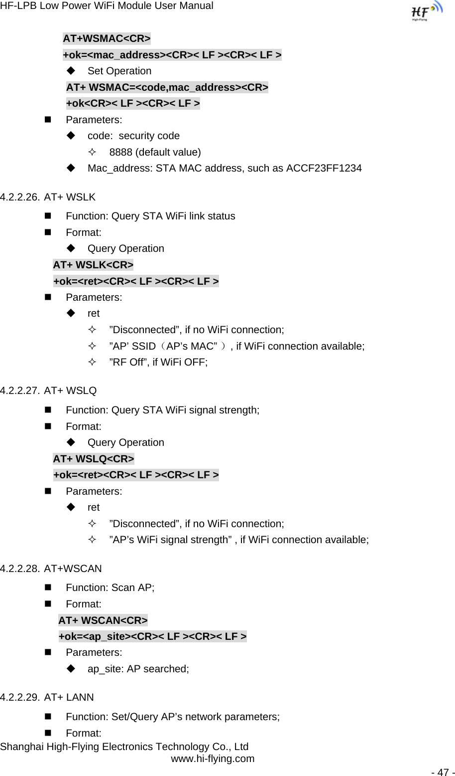
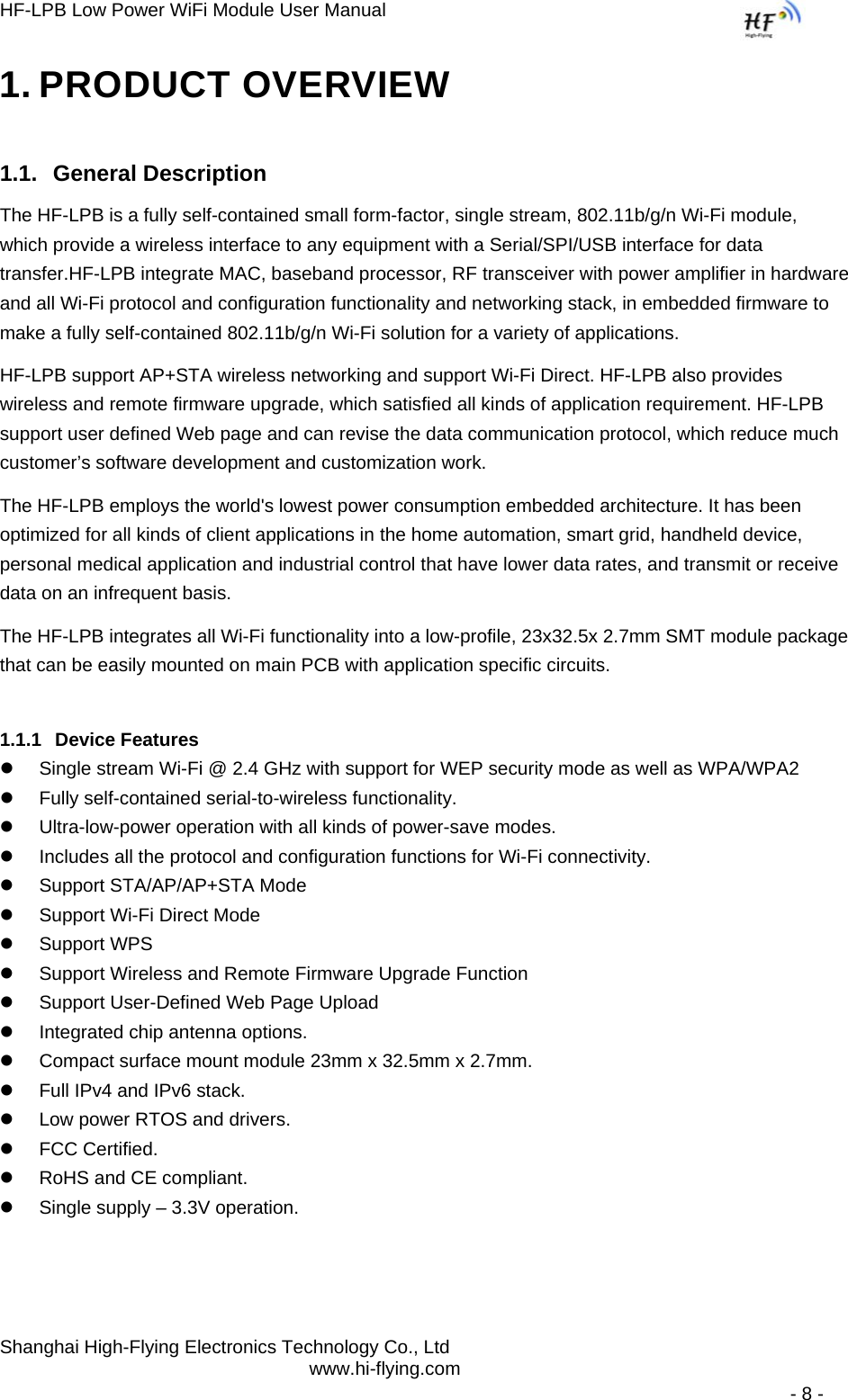
![HF-LPB Low Power WiFi Module User Manual Shanghai High-Flying Electronics Technology Co., Ltd www.hi-flying.com - 50 - Query Operation AT+ PSPAR<CR> +ok=<mode> <CR>< LF ><CR>< LF > Set Operation AT+ PSPAR=<mode> <CR>< LF ><CR>< LF > Parameters: mode: pf:Continuous TX Mode (NO WiFi OFF) ps1:Normal Mode, Disable DTIM (Default, 100ms interval) ps2:Normal Mode, Enable DTIM 4.2.2.36. AT+MSLP Function: Set/Query deep sleep/standby mode parameters; Format: Query Operation AT+ MSLP<CR> +ok=<ret><CR>< LF ><CR>< LF > Set Operation AT+ MSLP=<mode><CR>< LF ><CR>< LF > Parameters: ret: normal: normal mode (ps1: 100ms interval) deep sleep: deep sleep mode [WiFi OFF] standby: WiFi shut down mode mode: normal: normal mode (ps1: 100ms interval) dslp: deep sleep mode [WiFi OFF] standby: WiFi shut down mode Note: AT MSLP command can only be applied one time in every 10 second; 4.2.2.37. AT+MSOPT Function: Set/Query wake up option parameters; Format: Query Operation AT+ MSOPT<CR> +ok=<wakeup_mode> <CR>< LF ><CR>< LF > Set Operation AT+ MSOPT=<wakeup_mode> <CR>< LF ><CR>< LF > Parameters: Wakeup_mode: 0b0001:UART Wake up 0b0010:Pin Wake up 0b0100:Timeout Wake up Note: These 3 options can multi-selection, such as 0b0111 means all three wakes up option enabled.](https://usermanual.wiki/High-Flying-Electronics-Technology/HF-LPB/User-Guide-1937575-Page-50.png)