High Flying Electronics Technology HF-LPT220 HF-LPT220 User Manual GPON SFU System Design
High-Flying Electronics Technology Co., Ltd. HF-LPT220 GPON SFU System Design
UserManual.wiki
>
High Flying Electronics Technology
>
HF LPT220 User Manual
User manual
Navigation menu
Upload a User Manual
Namespaces
Wiki Guide
HTML
PDF
Info
Views
User Manual
Discussion / Help
Navigation
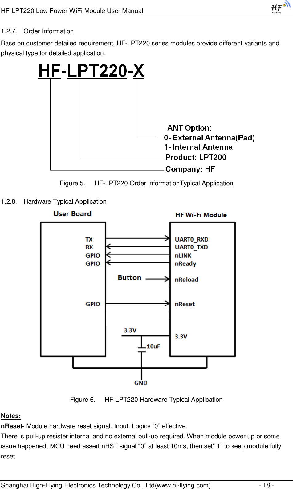

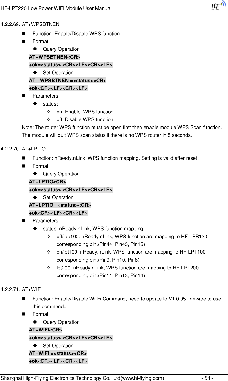
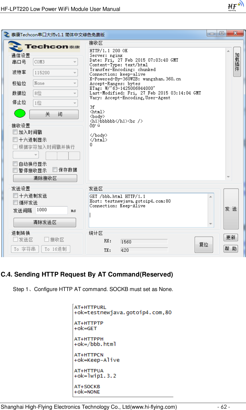
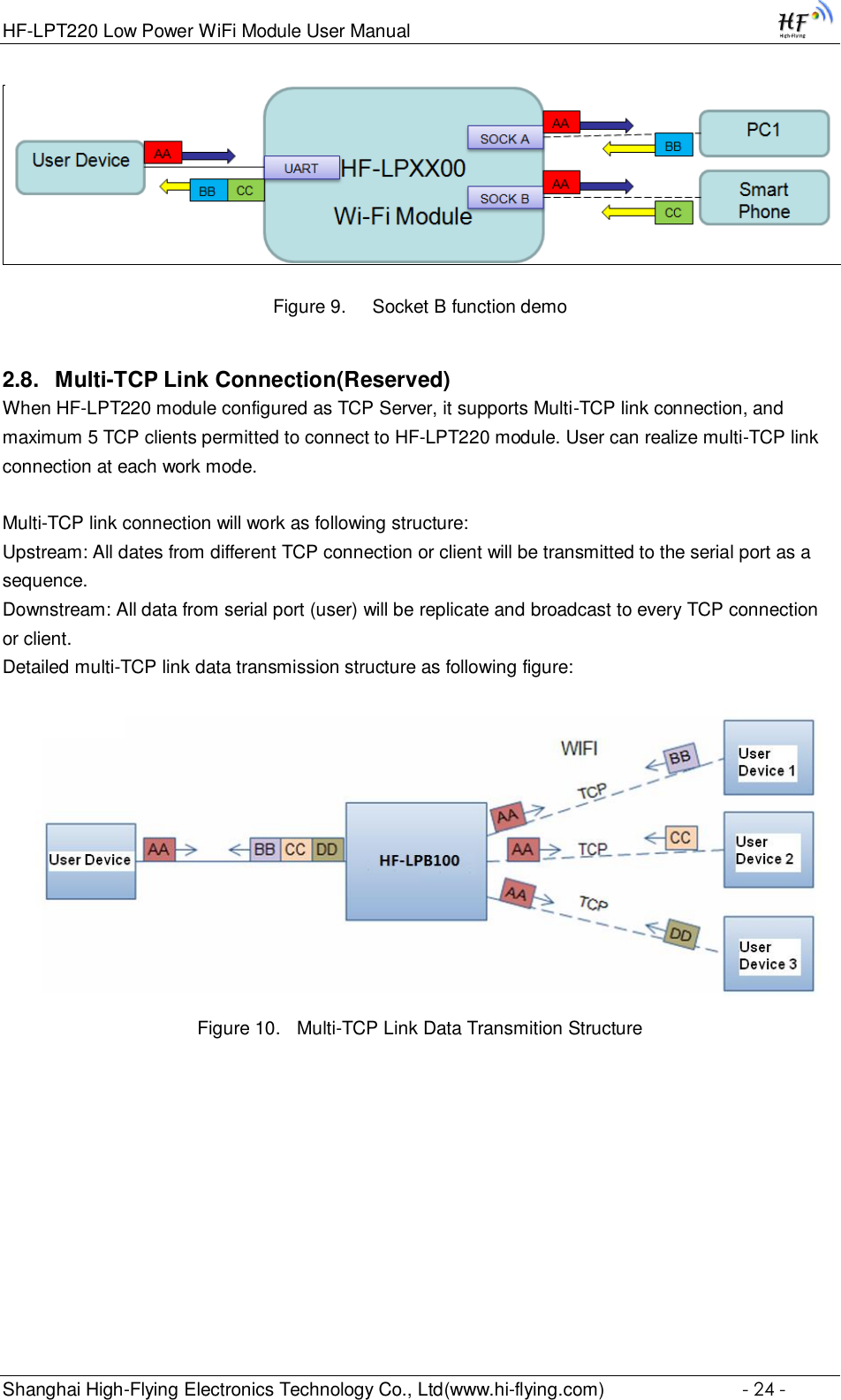
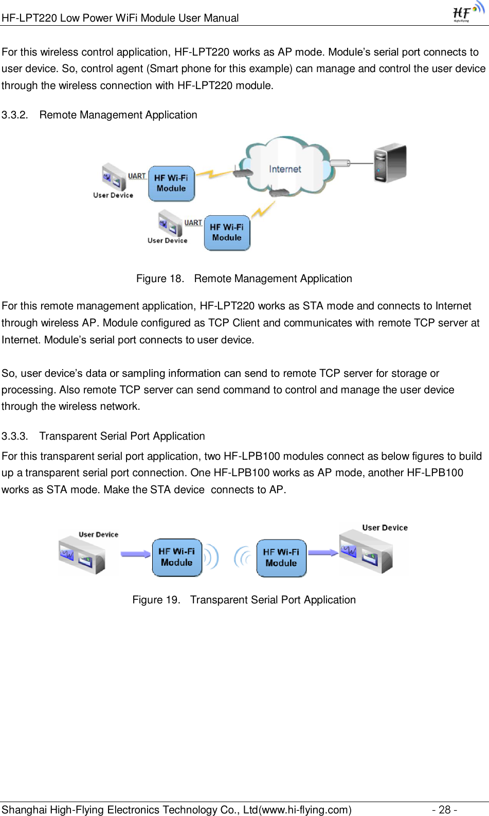
![HF-LPT220 Low Power WiFi Module User Manual Shanghai High-Flying Electronics Technology Co., Ltd(www.hi-flying.com) - 23 - HF-LPT220 module also support upgrade from remote HTTP server, keep module connects to AP router before execute remote HTTP upgrade. Remote upgrade have two methods: Direct Download and Upgrade, Configure File Based Upgrade. Configure File Based Upgrade AT+UPURL command to set the remote directory which the configuration file located, such as AT+UPURL=http://www.hi-flying.com/!admin/down/ Notes: The last ’/’ can’t be remove AT+UPFILE command to set the configuration file name, such as AT+UPFILE=config.txt AT+UPST command to start remote Application upgrade. After excuate this command, the module will firstly download configuration file (“config.txt”), then download the upgrade file base on the URL address listed in the configure file. General “config.txt” file format as following example: [URL]=http://10.10.100.100:80/lpb.bin [URL]= the URL address of Application. Direct Download and Upgrade AT+UPURL command to set the remote directory and file name, such as: AT+UPURL=http://www.hi-flying.com/!admin/down/,lpb.bin After excuate this command, the module will directly download the “lpb.bin” file from remote directory and start upgrade Application. Notes: please contact with high-flying technical people before upgrade firmware, or maybe damage the module and can’t work again. 2.7. SOCKET B Function HF-LPT220 support double socket communication.](https://usermanual.wiki/High-Flying-Electronics-Technology/HF-LPT220/User-Guide-3026039-Page-23.png)
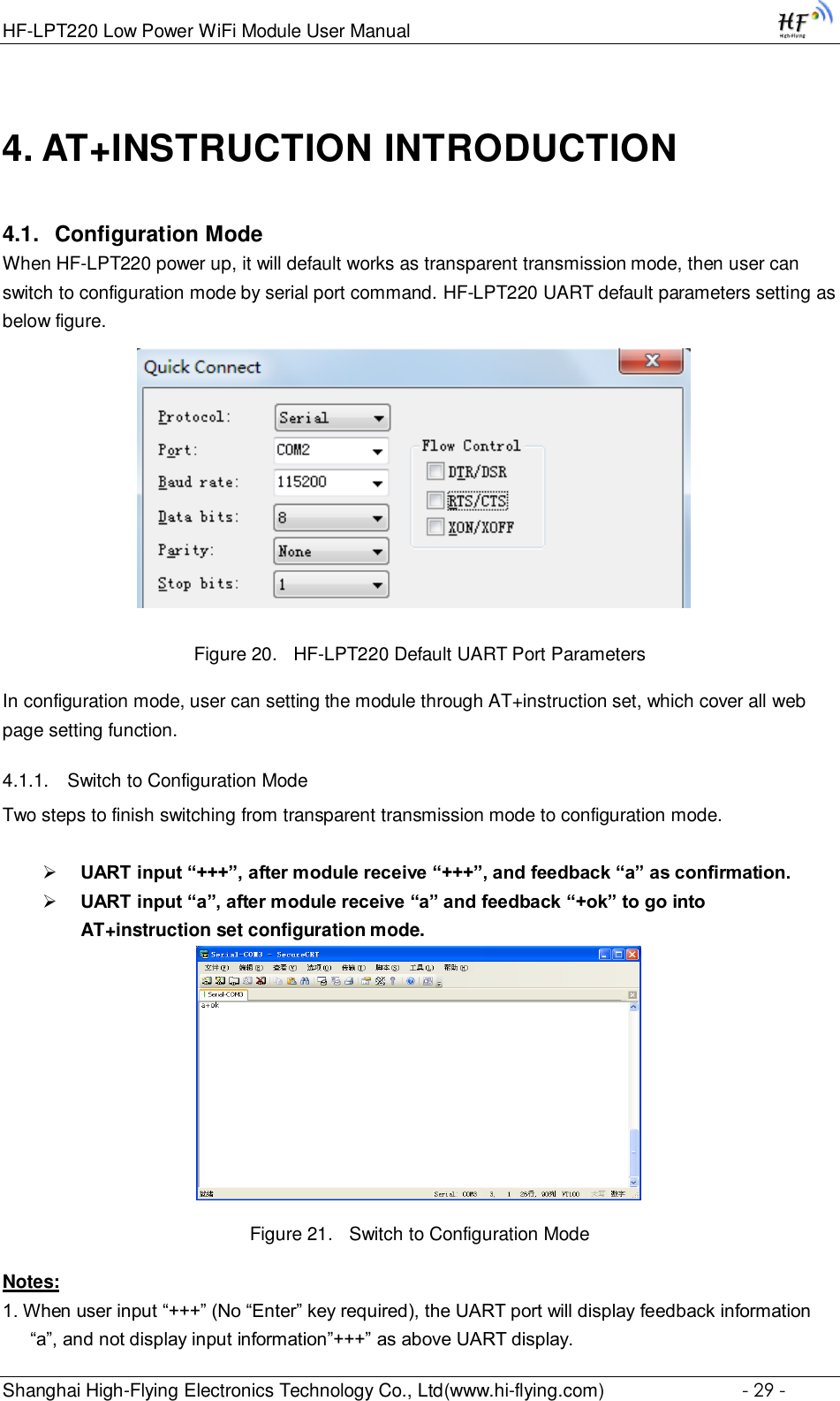
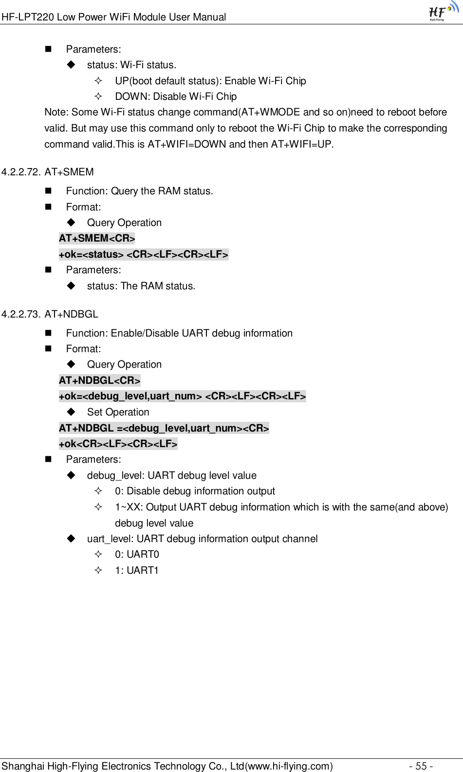
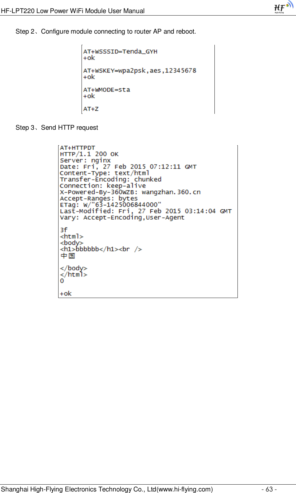
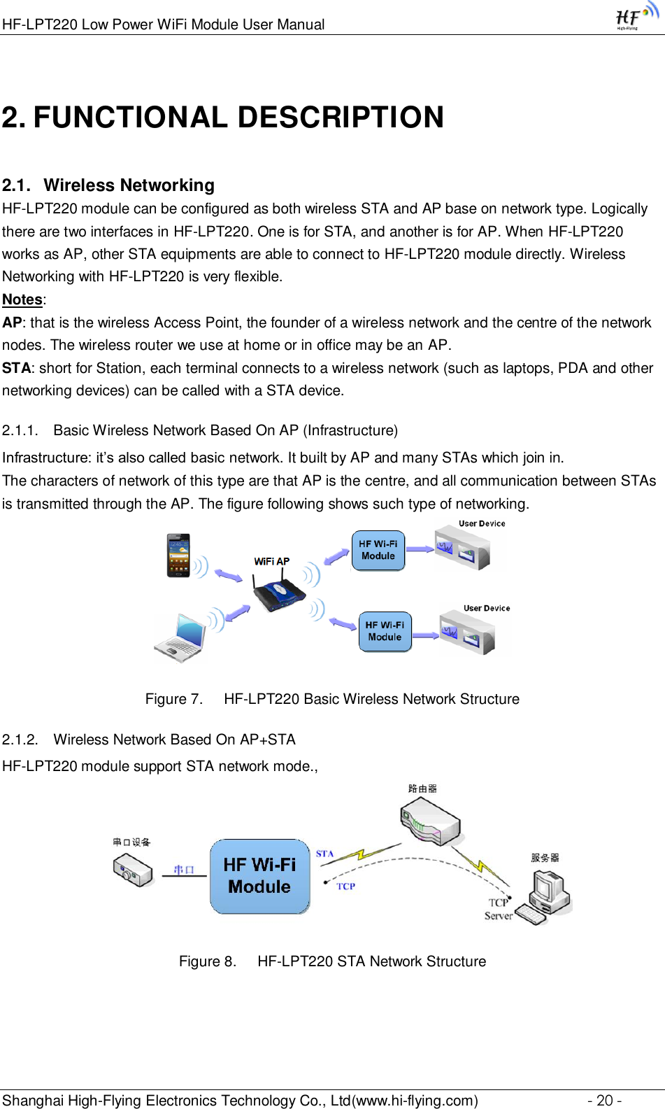
![HF-LPT220 Low Power WiFi Module User Manual Shanghai High-Flying Electronics Technology Co., Ltd(www.hi-flying.com) - 30 - 2. Any other input or wrong step to UART port will cause the module still works as original mode (transparent transmission). 3. “+++” and “a” should be input in a certain period of time to make the module switch to configuration mode. Like the following sequence. 4.2. AT+Instruction Set Overview User can input AT+Instruction through hyper terminal or other serial debug terminal, also can program the AT+Instruction to script. User can also input “AT+H” to list all AT+Instruction and description to start. Figure 22. ”AT+H” Instruction for Help 4.2.1. Instruction Syntax Format AT+Instruction protocol is based on the instruction of ASCII command style, the description of syntax format as follow. Format Description < >: Means the parts must be included [ ]: Means the optional part Command Message](https://usermanual.wiki/High-Flying-Electronics-Technology/HF-LPT220/User-Guide-3026039-Page-30.png)
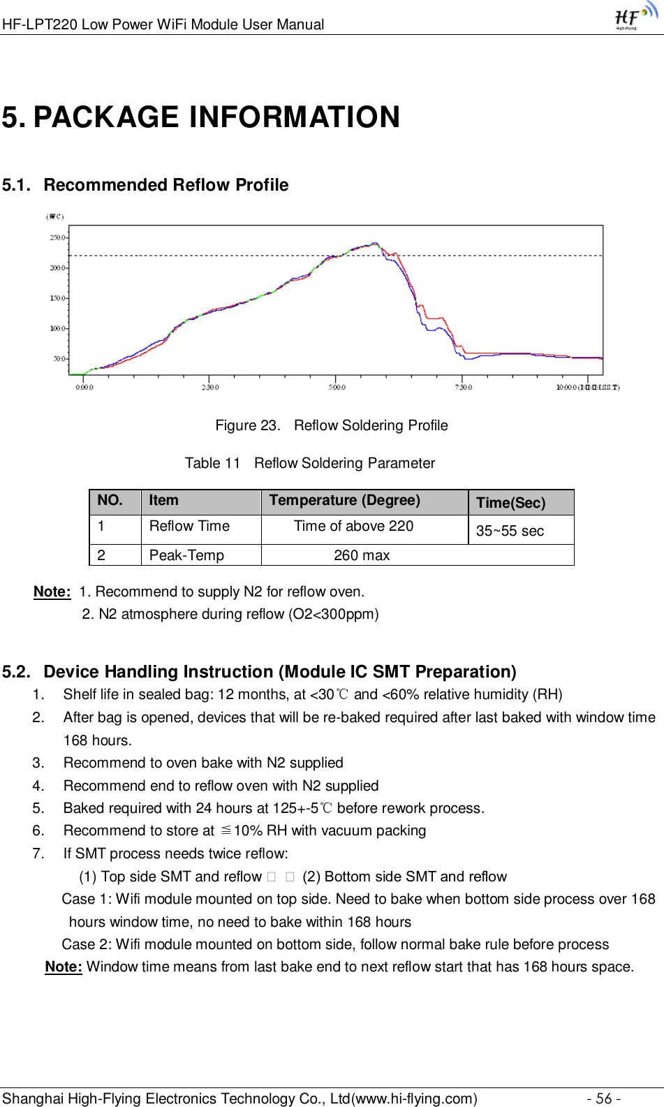
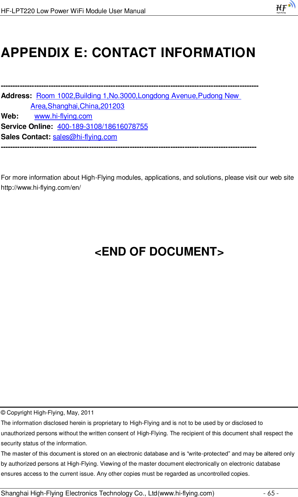
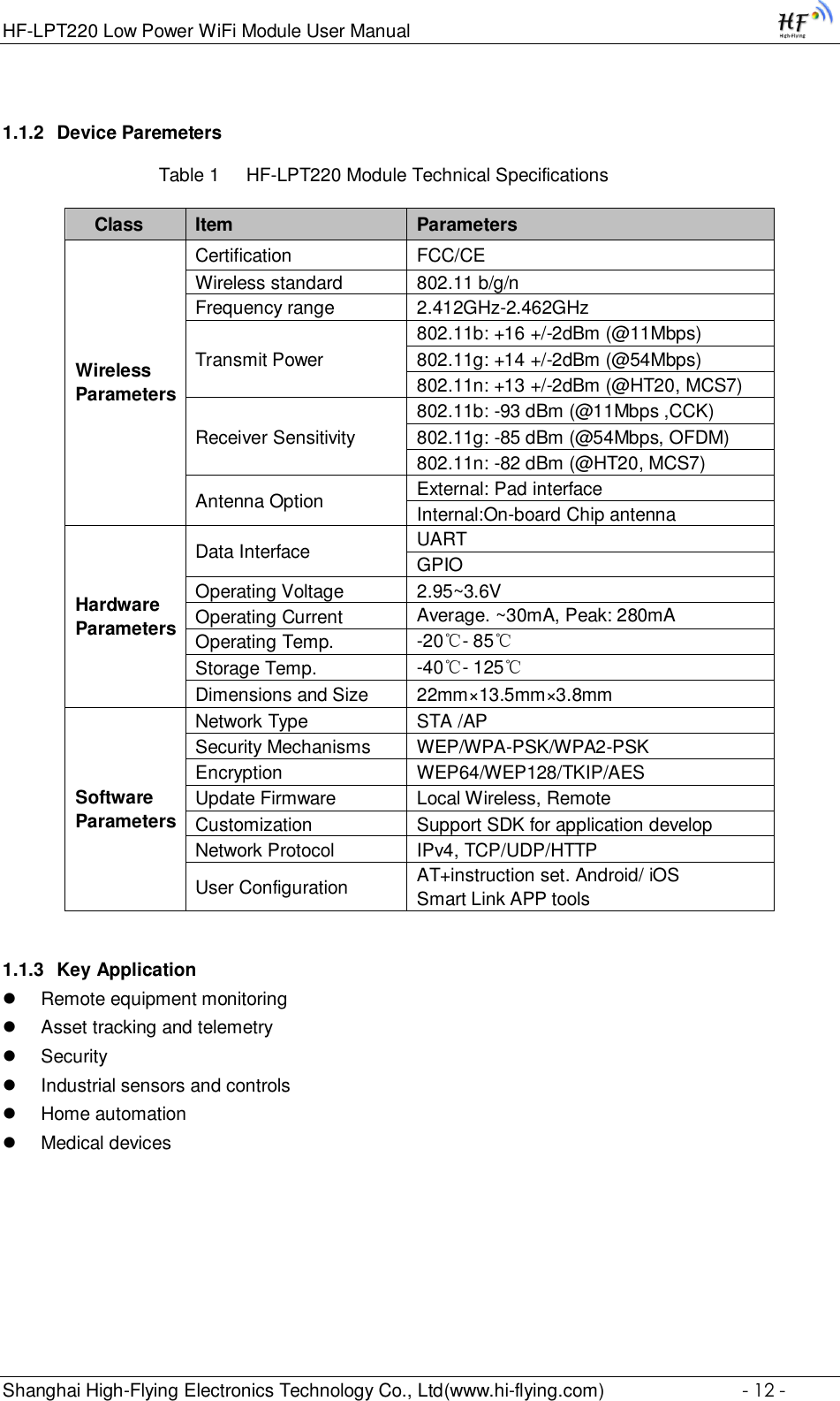
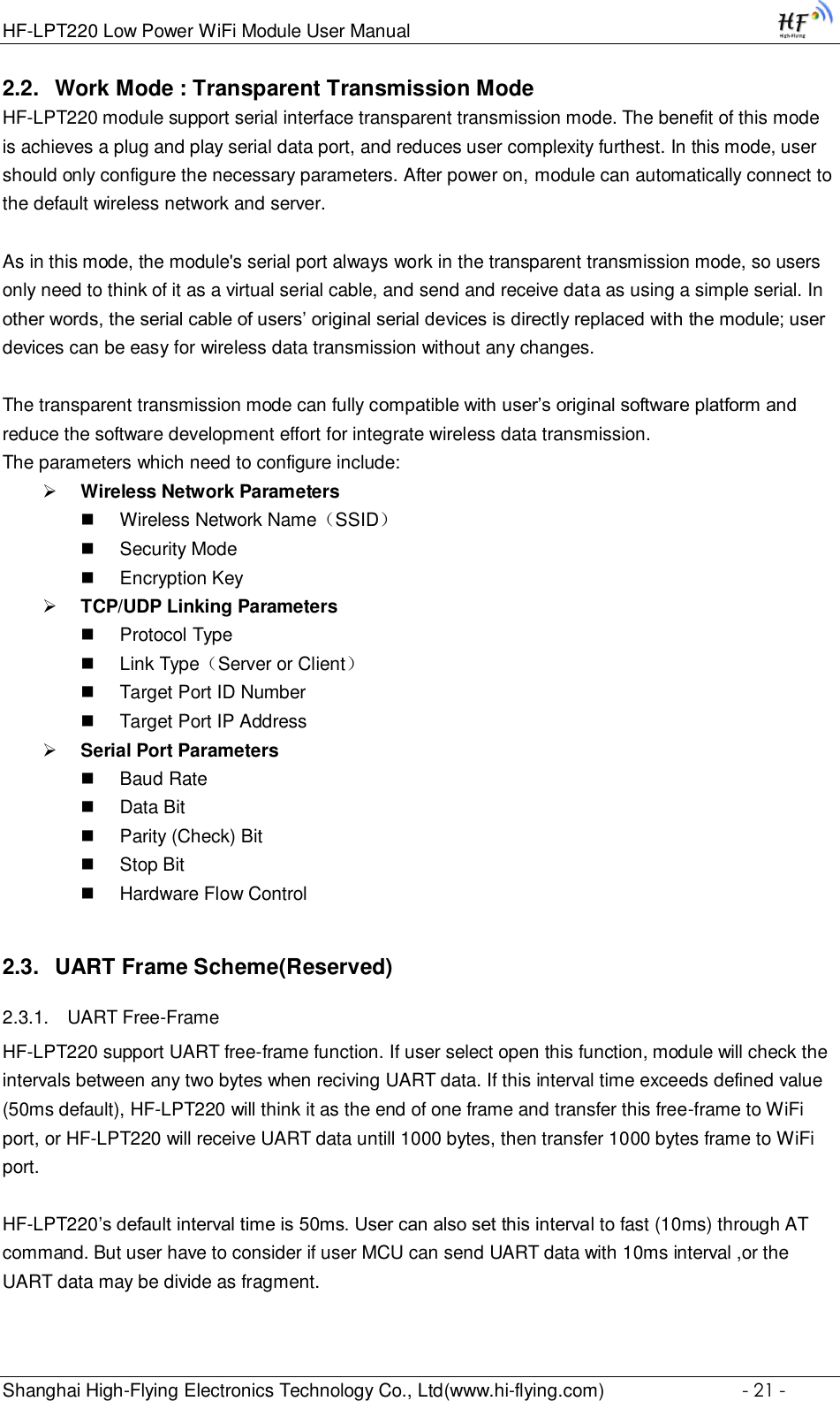
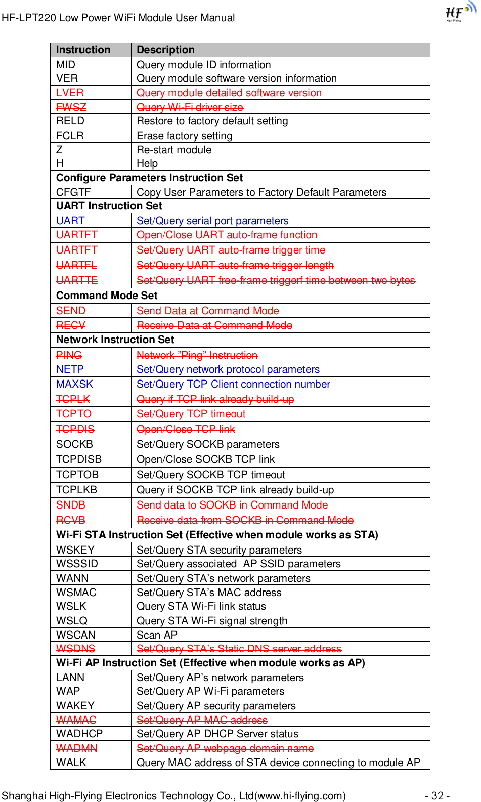
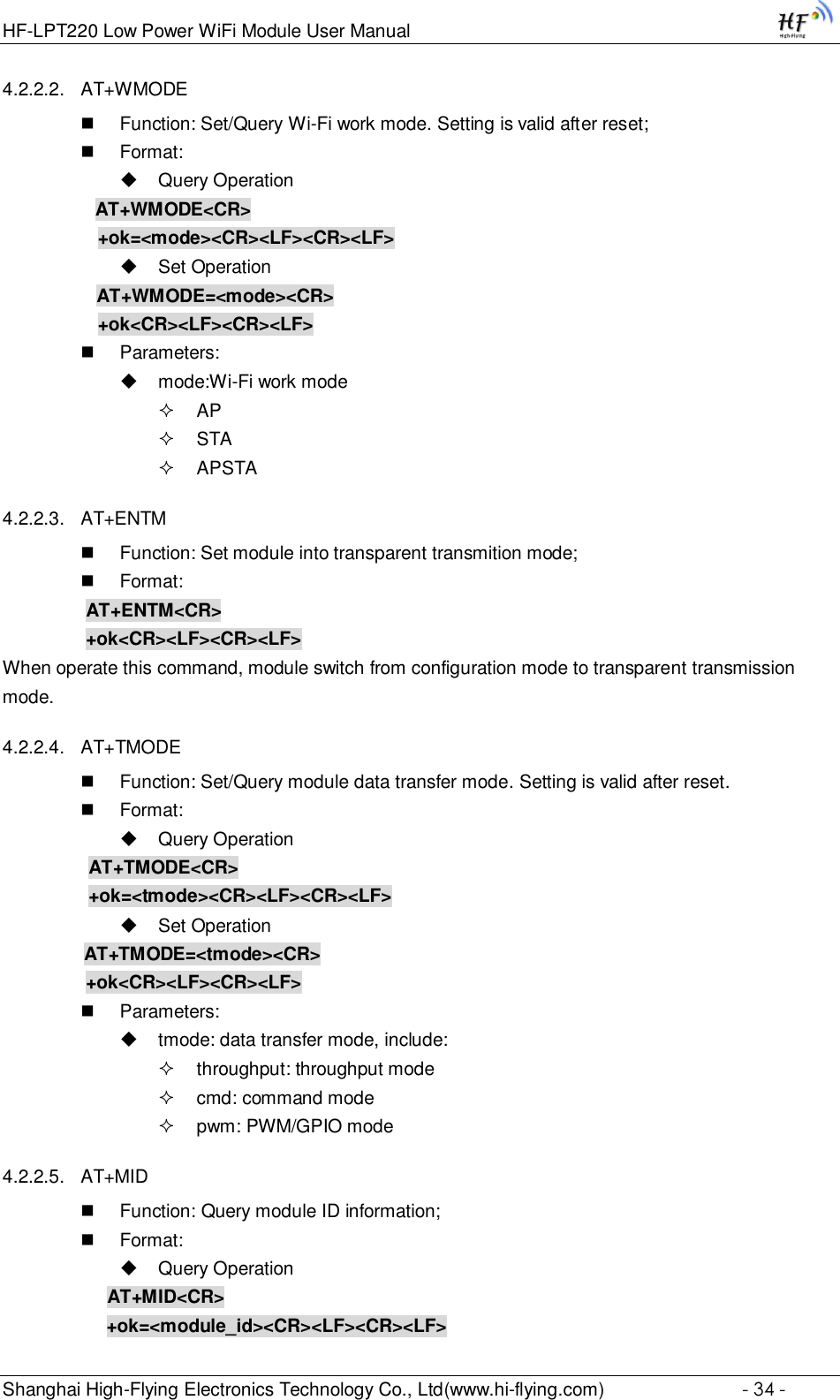
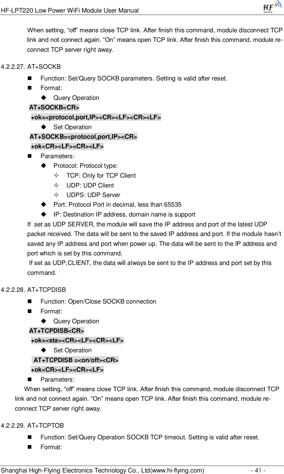
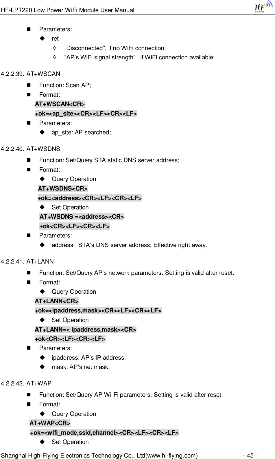
![HF-LPT220 Low Power WiFi Module User Manual Shanghai High-Flying Electronics Technology Co., Ltd(www.hi-flying.com) - 31 - AT+<CMD>[op][para-1,para-2,para-3,para-4…]<CR> AT+: Prefix of command message; CMD: Command string; [op]: Symbol of command operator, “=” : The command requires parameters input; “NULL”: Query the current command parameters setting; [para-n]: Parameters input for setting if required; <CR>:”Enter” Key, it’s 0x0a or 0x0d in ASCII; Notes: When input AT+Instruction, “AT+<CMD>” character will display capital letter automatic and other parts will not change as you input. Response Message +<RSP>[op] [para-1,para-2,para-3,para-4…]<CR><LF><CR><LF> +: Prefix of response message; RSP: Response string; “ok” : Success “ERR”: Failure [op] : = [para-n]: Parameters if query command or Error code when error happened; <CR>: ASCII 0x0d; <LF>: ASCIII 0x0a; Error Code Table 9 Error Code Describtion Error Code Description -1 Invalid Command Format -2 Invalid Command -3 Invalid Operation Symbol -4 Invalid Parameter -5 Operation Not Permitted 4.2.2. AT+Instruction Set Table 10 AT+Instruction Set List Instruction Description <null> NULL Managment Instruction Set E Open/Close show back function WMODE Set/Query Wi-Fi work mode (AP/STA) ENTM Set module into transparent transition mode TMODE Set/Query module data transfer mode](https://usermanual.wiki/High-Flying-Electronics-Technology/HF-LPT220/User-Guide-3026039-Page-31.png)
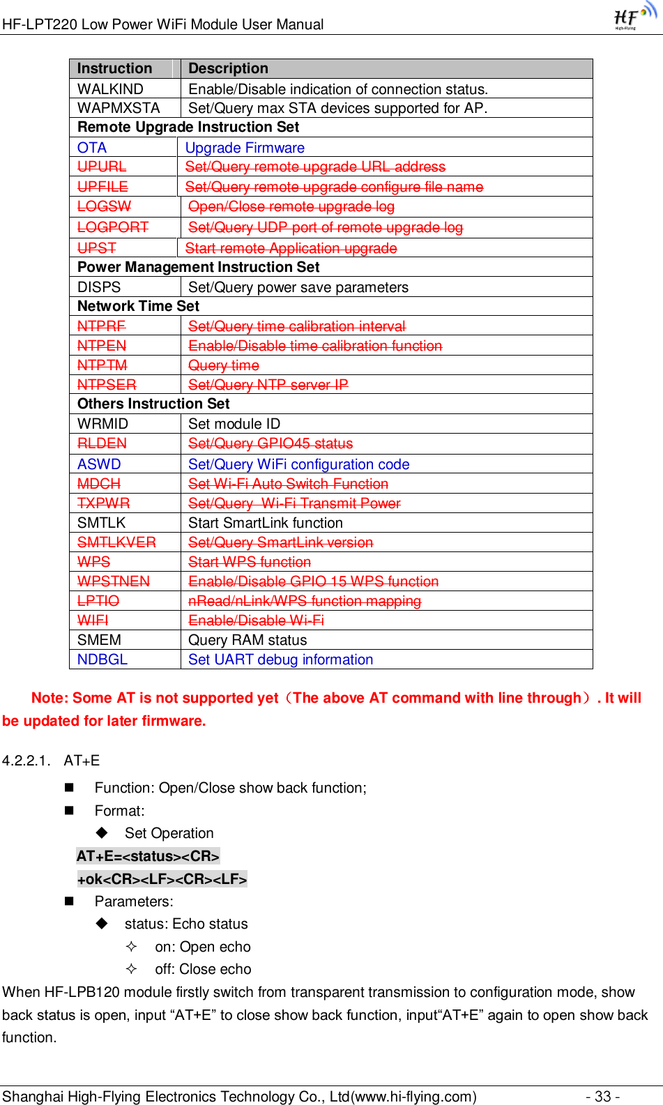
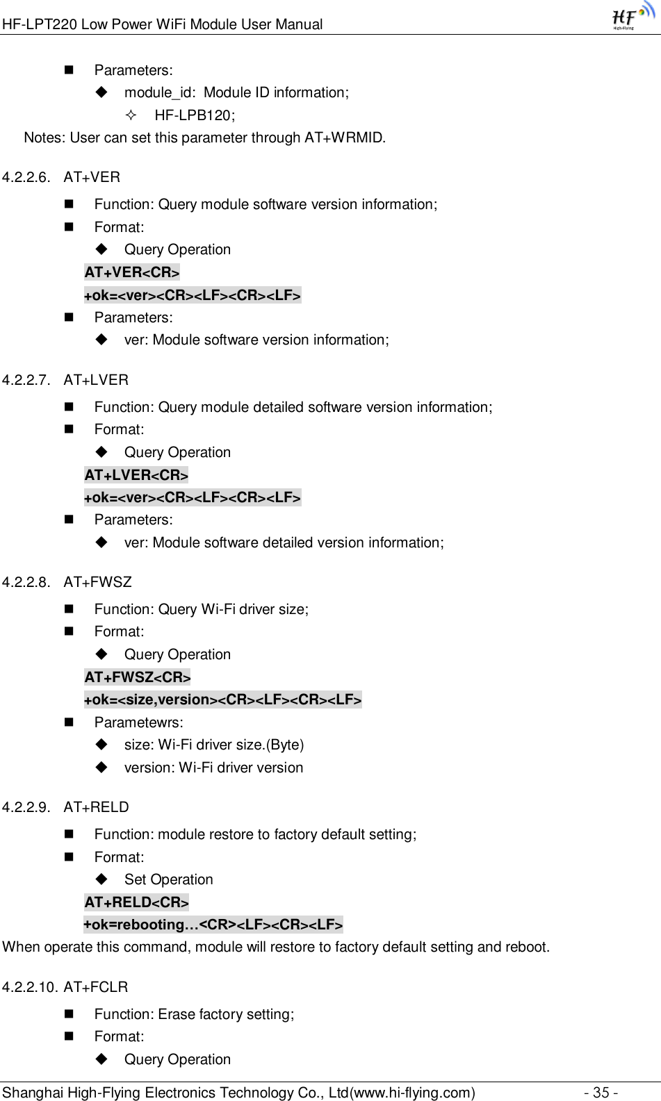
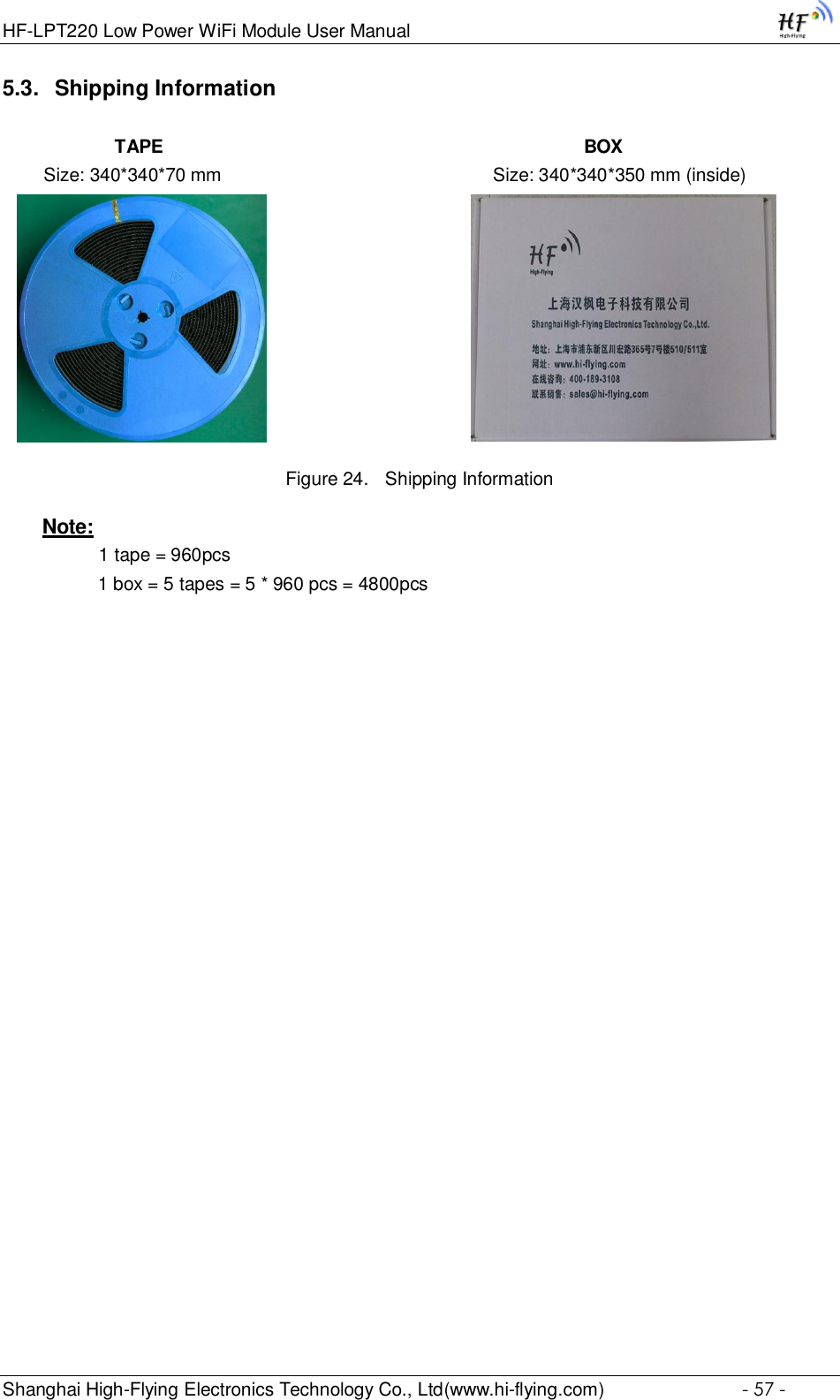
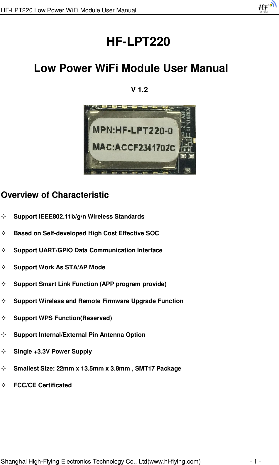
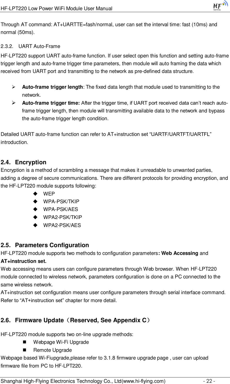
![HF-LPT220 Low Power WiFi Module User Manual Shanghai High-Flying Electronics Technology Co., Ltd(www.hi-flying.com) - 36 - AT+FCLR<CR> +ok=<status><CR><LF><CR><LF> 4.2.2.11. AT+Z Function: Re-start module; Format: AT+Z<CR> 4.2.2.12. AT+H Function: Help; Format: Query Operation AT+H<CR> +ok=<command help><CR><LF><CR><LF> Parameters: command help: command introduction; 4.2.2.13. AT+CFGTF Function: Copy User Parameters to Factory Default Parameters; Format: Query Operation AT+CFGTF<CR> +ok=<status><CR><LF><CR><LF> Parameters: status: feedback operation status; 4.2.2.14. AT+UART Function: Set/Query serial port parameters. Setting is valid after reset. Format: Query Operation AT+UART[=uart_num]<CR> +ok=<baudrate,data_bits,stop_bit,parity,flowctrl><CR><LF><CR><LF> Set Operation AT+UART=<baudrate,data_bits,stop_bit,parity,flowctrl>[,uart_num]<CR> +ok<CR><LF><CR><LF> Parameters: uart_num:UART Channel, the default is UART0. 0:UART0 Channel 1:UART1 Channel baudrate: 1200,1800,2400,4800,9600,19200,38400,57600,115200,230400, 380400,460800,921600 data_bits: 8 stop_bits:](https://usermanual.wiki/High-Flying-Electronics-Technology/HF-LPT220/User-Guide-3026039-Page-36.png)
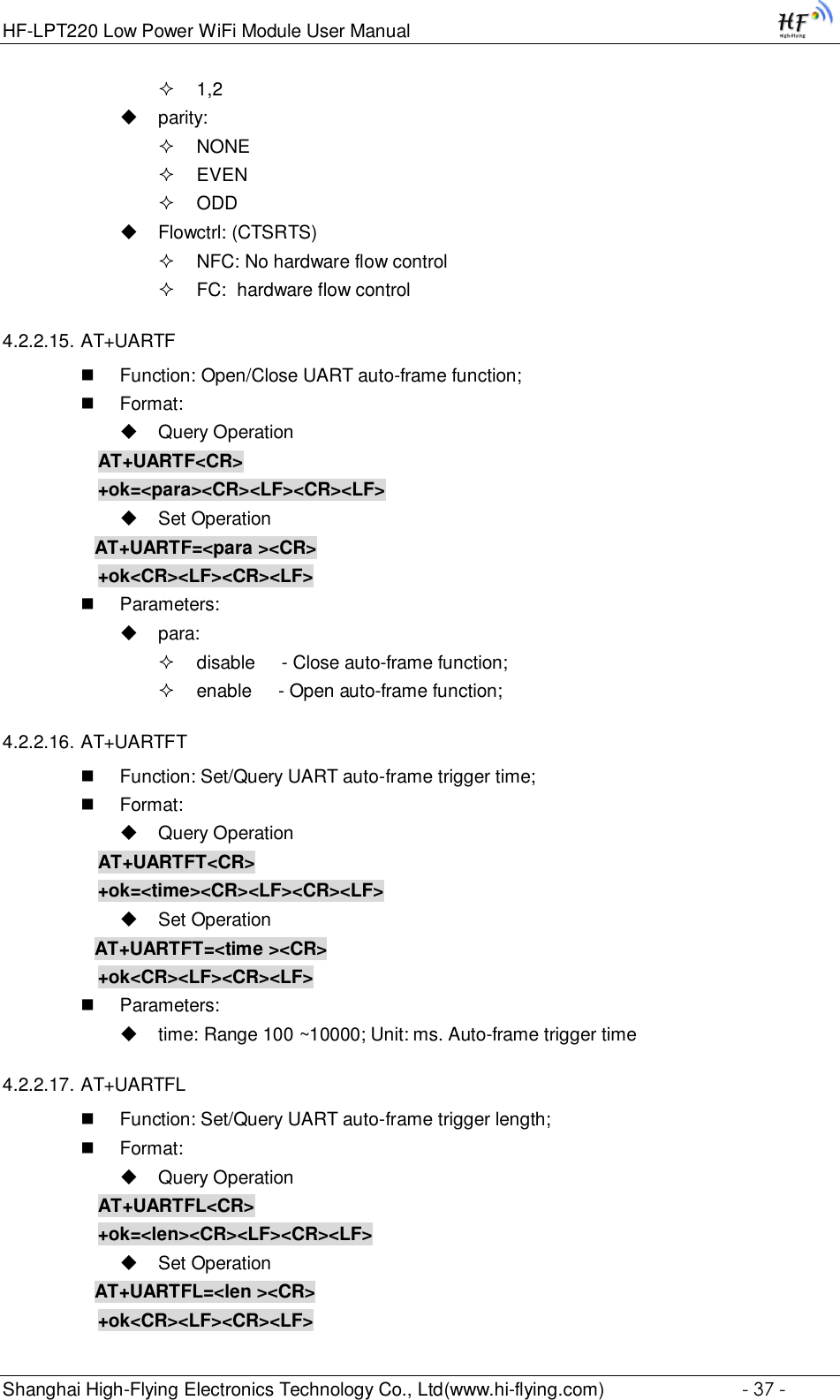
![HF-LPT220 Low Power WiFi Module User Manual Shanghai High-Flying Electronics Technology Co., Ltd(www.hi-flying.com) - 47 - Query Operation AT+WADHCP<CR> +ok=<status>,<ip1>,<ip2><CR><LF><CR><LF> Set Operation AT+WADHCP=<status>[,ip1,ip2]<CR> +ok<CR><LF><CR><LF> Parameters: status:AP’s DHCP server function status: on:DHCP Server Open; off:DHCP Server Close: ip1: DHCP allocate IP start value. ip2: DHCP allocate IP end value. 4.2.2.46. AT+WADMN Function: Set/Query AP webpage domain name; Format: Query Operation AT+WADMN<CR> +ok=<domain_name><CR><LF><CR><LF> Set Operation AT+WADMN=<domain_name><CR> +ok<CR><LF><CR><LF> Parameters: Domain_name: Webpage domain name (within 20 characters, can’t all numbers). 4.2.2.47. AT+WALK Function: Query MAC address of STA device connecting to module AP Format: Query Operation AT+WALK<CR> +ok=<status> <CR><LF><CR><LF> Parameters: status: MAC address of STA device connecting to module AP. No Connection: No STA device connecting to module AP; 4.2.2.48. AT+WALKIND Function: Enable/Disable indication of module AP connection status. Format: Query Operation AT+WALKIND<CR> +ok=<status> <CR><LF><CR><LF> Set Operation AT+WALKIND=<status><CR> +ok<CR><LF><CR><LF>](https://usermanual.wiki/High-Flying-Electronics-Technology/HF-LPT220/User-Guide-3026039-Page-47.png)
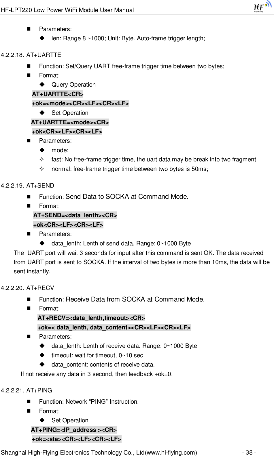
![HF-LPT220 Low Power WiFi Module User Manual Shanghai High-Flying Electronics Technology Co., Ltd(www.hi-flying.com) - 52 - off: nReload pin function is disabled 4.2.2.63. AT+ASWD Function: Set/Query WiFi Configuration Password; Format: Query Operation AT+ASWD<CR> +ok=<aswd> <CR><LF><CR><LF> Set Operation AT+ASWD=<aswd> <CR><LF><CR><LF> Parameters: aswd: WiFi Configuration Password (within 20 characters). 4.2.2.64. AT+MDCH Function: Set Wi-Fi Auto Switch Function. Setting is valid after reset. Format: Query Operation AT+MDCH<CR> +ok=<mode> <CR><LF><CR><LF> Set Operation AT+MDCH=<mode> <CR><LF><CR><LF> Parameters: mode: Wi-Fi Auto Switch Mode off: Disable Wi-Fi auto switch. on: Enable Wi-Fi auto switch. When the module(STA mode) fail to connect to router, it will switch to AP mode itself in one minute. auto: Enable Wi-Fi auto detect function. The module will reset itself when encounter any abnormal. The default time interval is 10 minutes. (default mode) 3-120: unit: minute. Set the time interval to reset itself when abnormal. 4.2.2.65. AT+TXPWR Function: Set/Query Wi-Fi Transmit Power, Real Transmit Power=Default Transmit Power(16dBm) – [Setting Value] * 0.5dBm. Setting is valid after reset. Format: Query Operation AT+TXPWR <CR> +ok=<num><CR><LF><CR><LF> Set Operation AT+TXPWR=<num><CR> +ok<CR><LF><CR><LF> Parameters:](https://usermanual.wiki/High-Flying-Electronics-Technology/HF-LPT220/User-Guide-3026039-Page-52.png)
![HF-LPT220 Low Power WiFi Module User Manual Shanghai High-Flying Electronics Technology Co., Ltd(www.hi-flying.com) - 53 - num: [Setting Value]. The default is 0, it can be sent from 0 ~ 24. If set to 24, the moudule transmit power will be at a minium of 4dBm. Reboot to make this setting change valid. It will not restore to default if reload the module. 4.2.2.66. AT+SMTLK Function: Start SmartLink function Format: Query Operation AT+SMTLK<CR> SmartLink is a One-Key config function. Config the module connecting to router easily. After start SmartLink function , the module work in SmartLink status and nLink LED is fast flashing waiting for APP to push information. See the Appendix for more details. 4.2.2.67. AT+SMTLKVER Function: Set/Query SmartLink config version(for LPB100U only) Format: Query Operation AT+SMTLKVER <CR> +ok=<status><CR><LF><CR><LF> Set Operation AT+SMTLKVER=<ver><CR> +ok<CR><LF><CR><LF> Parameters: status: SmartLink config version。 SMTLK 3.0: SmartLink V3 version, sniffer mode. SMTLK 4.0: SmartLink V4 version, sonic mode ver:3- Use SmartLink V3 version, sniffer mode, 4- SmartLink V4 version, sonic mode. The corresponding APP can be downloaded from our website. See appendix D for details. 4.2.2.68. AT+WPS Function: Start WPS function Format: Query Operation AT+WPS<CR> +ok=<status> <CR><LF><CR><LF> Parameters: status: WPS status. The module will reboot and work in STA mode connecting to specific router when WPS communication is OK. WPS Scan Failed: WPS communication is failed. Note: The router WPS function must be open first then enable module WPS Scan function. The module will quit WPS scan status if there is no WPS router in 5 seconds. If the router's WPS is enabled, the module will reboot and enter WPS mode without reply +ok.](https://usermanual.wiki/High-Flying-Electronics-Technology/HF-LPT220/User-Guide-3026039-Page-53.png)