Hilti PR2XR01 Levelling and alignment instrument User Manual
Hilti Corporation Levelling and alignment instrument Users Manual
UserManual.wiki
>
Hilti
>
PR2XR01 User Manual
Users Manual
Navigation menu
Upload a User Manual
Namespaces
Wiki Guide
HTML
PDF
Info
Views
User Manual
Discussion / Help
Navigation


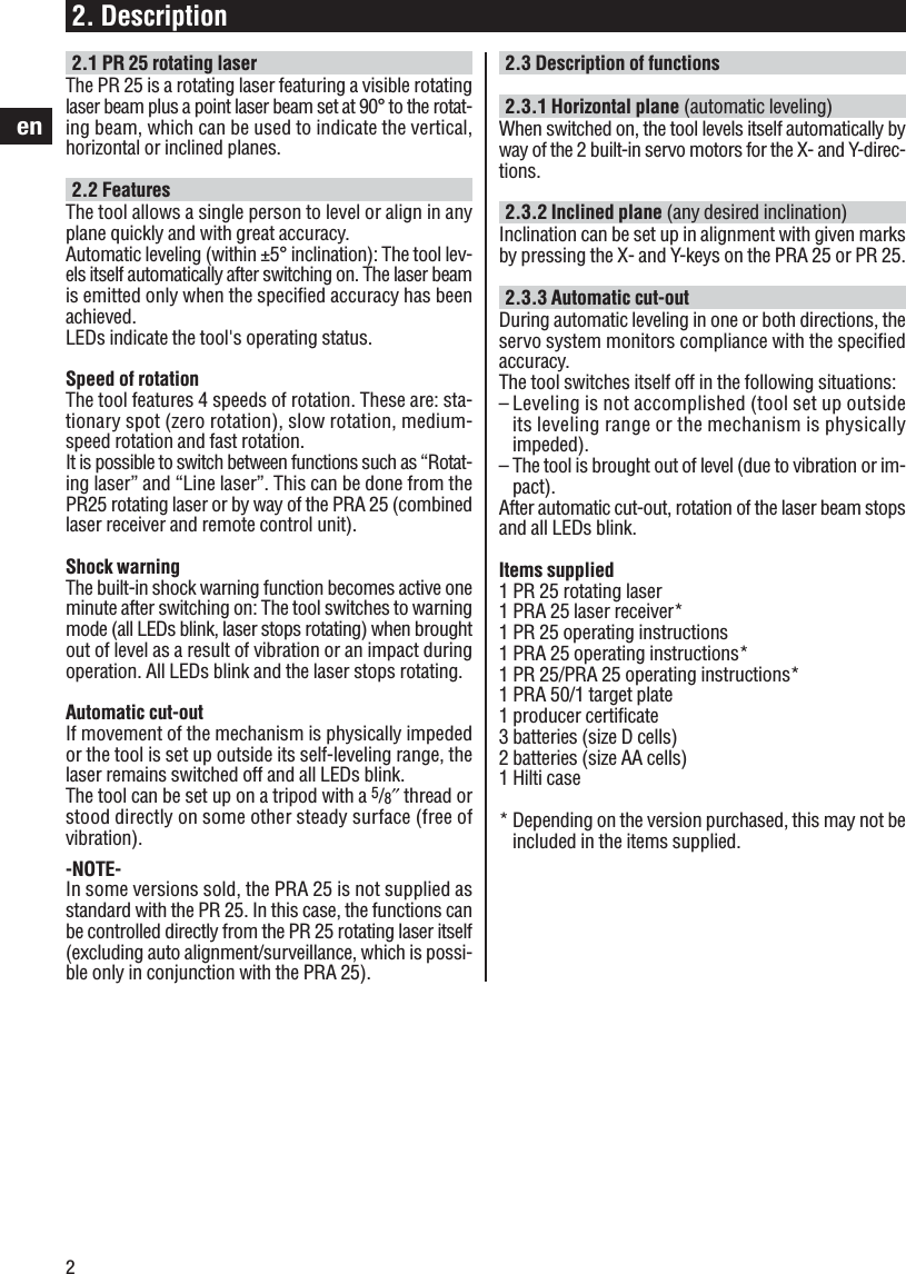
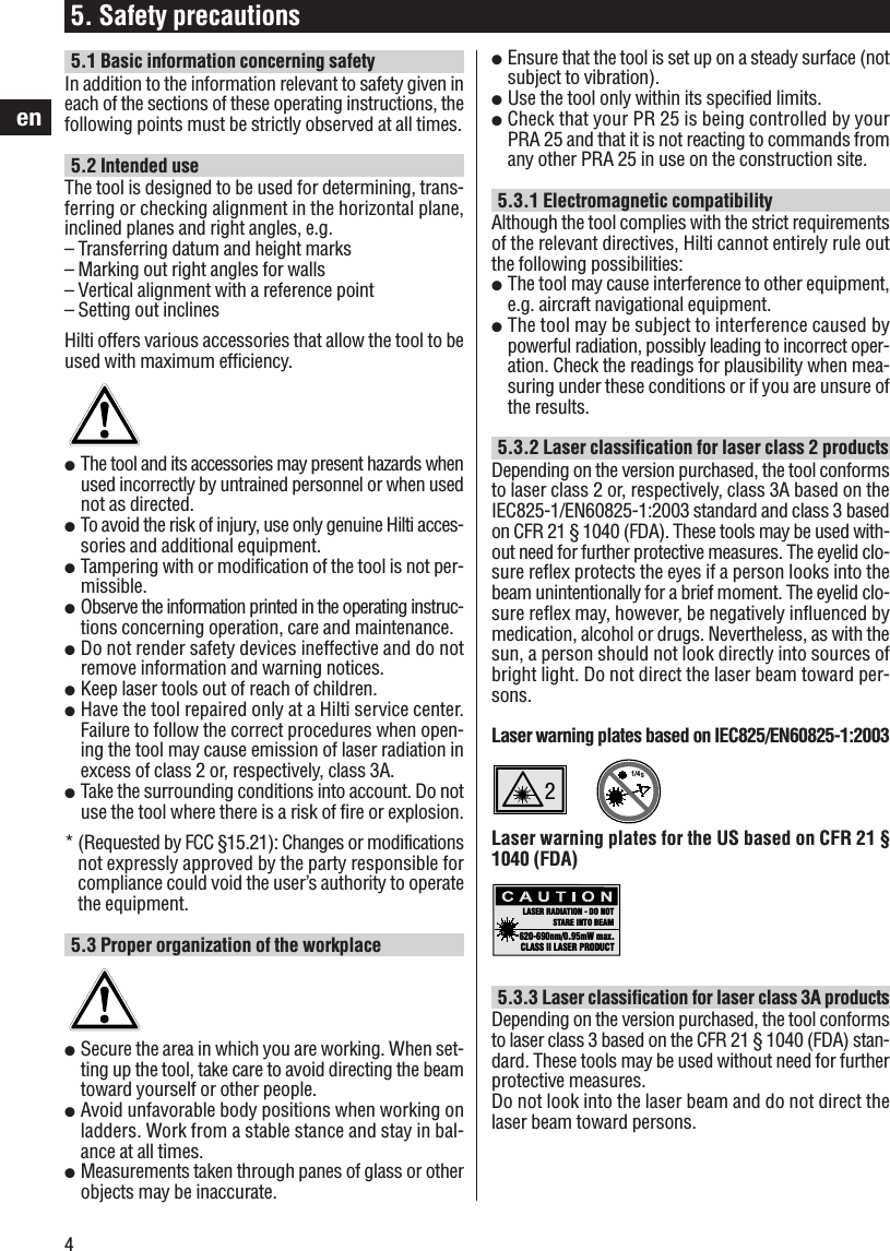
![3en4. Technical data for the PR 25Range (diameter)Range of remote controlAccuracy (at 24 °C/+75 °F)Plumb beamLaser product classSpeeds of rotationSelf-leveling rangeAutomatic cut-outOperating status indicatorsPower supplyBattery life at 20 °C [+68 °F]Operating temperatureStorage temperatureProtection classTripod threadWeightDimensionsBeam diameterRight of technical changes reserved.2 to 200 m [6 to 650 ft.] with the PRA 250 to 100 m [0 to 325 ft.] with the PRA 25±0.75 mm @ 10 mContinuously at right angles to plane of rotationClass 2, visible, 635 nm, < 1 mWClass 3A, visible, 635 nm, < 2.5 mW(IEC825-1/EN60825-1:2003; FDA 21 CFR 1040)Zero, slow, medium, fast(operating speed)±5°, LED indicatorWhen the laser is brought out of level (unless bothaxes set to inclined mode):– Rotation stops– All LEDs blink– Auto leveling LED– Battery condition LED– Shock warning LED– X and Y inclination/direction LED3 size D alkaline batteries or NiMH rechargeable bat-tery for charging with PUA 80 charger (accessory)Alkaline batteries: > 50 hoursNiMh batteries: > 40 hours–20 °C to +50 °C [–4 °F to +122 °F]–30 °C to +60 °C dry [–22 °F to +140 °F]IP 56 (as per IEC 529)5/8″x 18Approx. 2.4 kg (5.3 lbs.) including 3 batteries186 (L) x 186 (W) x 213 (H) mm [7.3″ (L) x 7.3″ (W) x 8.4″ (H) inches]< 16 mm at 10 m3. Accessories3.1 Accessories for the PR 25Many tasks can be carried out much more efficientlywhen the appropriate accessories for the PR 25 are used.The following accessories are available:– PRA 20 and PRA 25 laser receiver– PRA 50 and PRA 51 target plates– PRA 52 slope calculator– PRA 70 and PRA 71 wall mounts– PRA 76 slope adapter– PRA 75 laser receiver holder– PUA 80 charger and PRA 801 battery pack– PA 375 batter board adapter, PA 377 tripod and facadeadapter– PA 910, PA 911, PA 921 and PA 931/2 tripods– PA 950/960 and PA 951/961 telescopic staffs](https://usermanual.wiki/Hilti/PR2XR01/User-Guide-515696-Page-7.png)