Hilti PR3XR02 Rotating Laser User Manual PR 300HV2S ENU USA
Hilti Corporation Rotating Laser PR 300HV2S ENU USA
Hilti >
Contents
- 1. User manual
- 2. User Manual
- 3. Manual_
User Manual

Hilti Corporation
FL‑9494 Schaan
Tel: +423 / 234 21 11
Fax: +423 / 234 29 65
www.hilti.com
Hilti = registered trademark of Hilti Corp., Schaan NUMMER DATE Pos. POS-ZAHL LIEFERANTEN-NR Printed in Liechtenstein © 2015
Right of technical and programme changes reserved S:E: & O.
z
DOC-ARTIKELNR/REF-STAND
PR 300-HV2S
Operating instructions en
1
23
4
5 6
78
9
10
11 12
13 14
15 16
17
18
19
20
21

ORIGINAL OPERATING INSTRUCTIONS
PR 300-HV2S rotating laser
It is essential that the operating instructions
are read before the tool is operated for the
first time.
Always keep these operating instructions to-
gether with the tool.
Ensure that the operating instructions are
with the tool when it is given to other persons.
Contents Page
1 General information 2
2 Safety instructions 2
3 Description 4
4 Technical data 7
5 Before use 8
6 Operation 10
7 Care and maintenance 19
8 Troubleshooting 20
9 Disposal 22
10 Manufacturer’s warranty - tools 22
11 FCC statement (applicable in US) / IC
statement (applicable in Canada) 22
1These numbers refer to the illustrations. You can
find the illustrations at the beginning of the operating
instructions.
In these operating instructions, the designation “the tool”
or “the rotating laser” always refers to the PR 300-HV2S.
“Remote control”, “laser receiver” or “receiver” always
refer to the PRA 300.
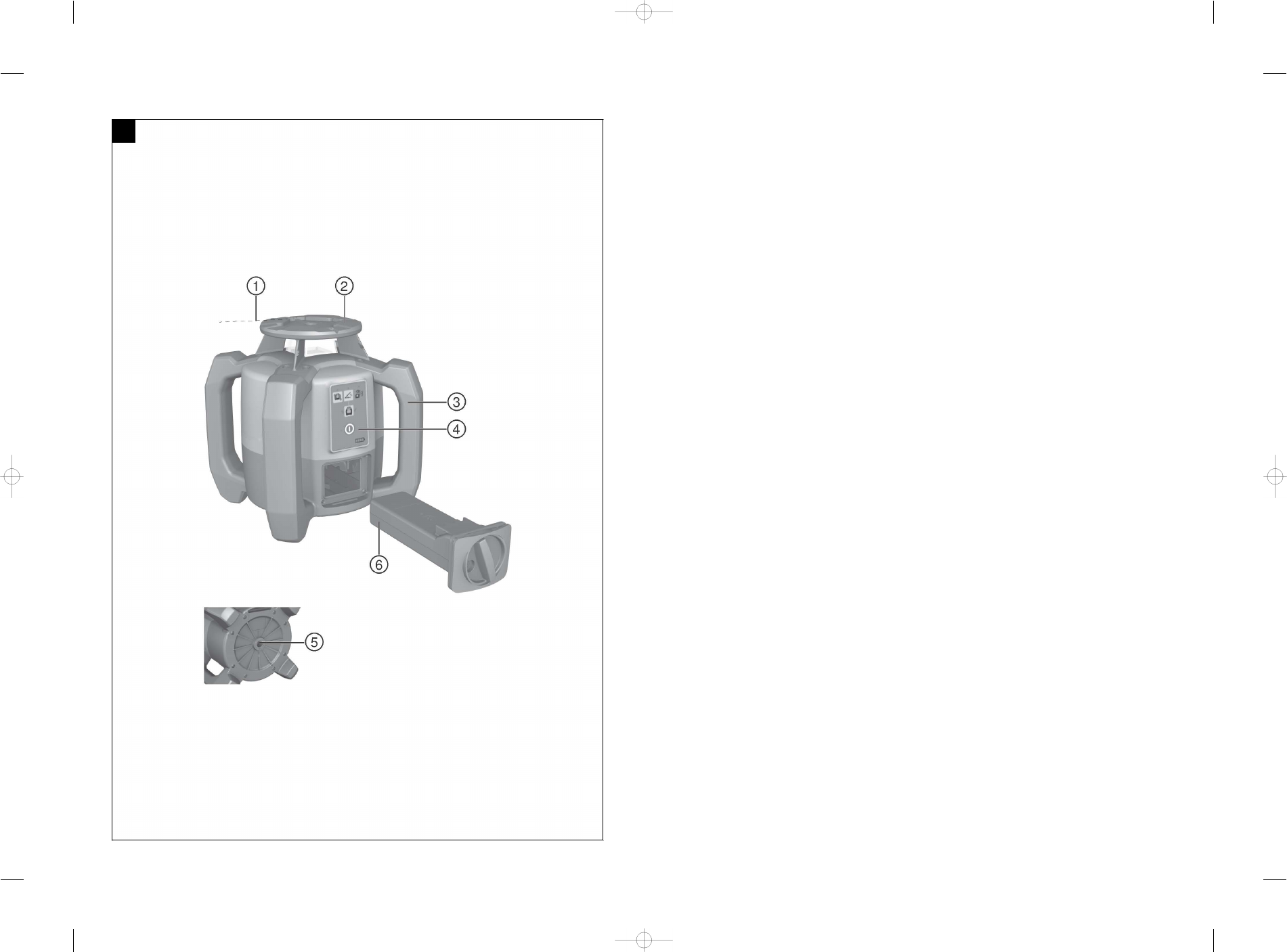
Rotating laser 1
@Laser beam (plane of rotation)
;Rotating head
=Pentaprism
%Grip
&Control panel
(Base plate with ⁵/₈" thread
)PRA 84 Li-Ion battery
Battery compartment 2
@PRA 84 Li-Ion battery
;Battery compartment
=Catch
Charging the battery in the tool 3
@PUA 81 AC adapter
;Charging socket
Charging the battery externally (not in the tool) 4
@PUA 81 AC adapter
;PUA 82 motor vehicle power adapter
=Charging activity LED
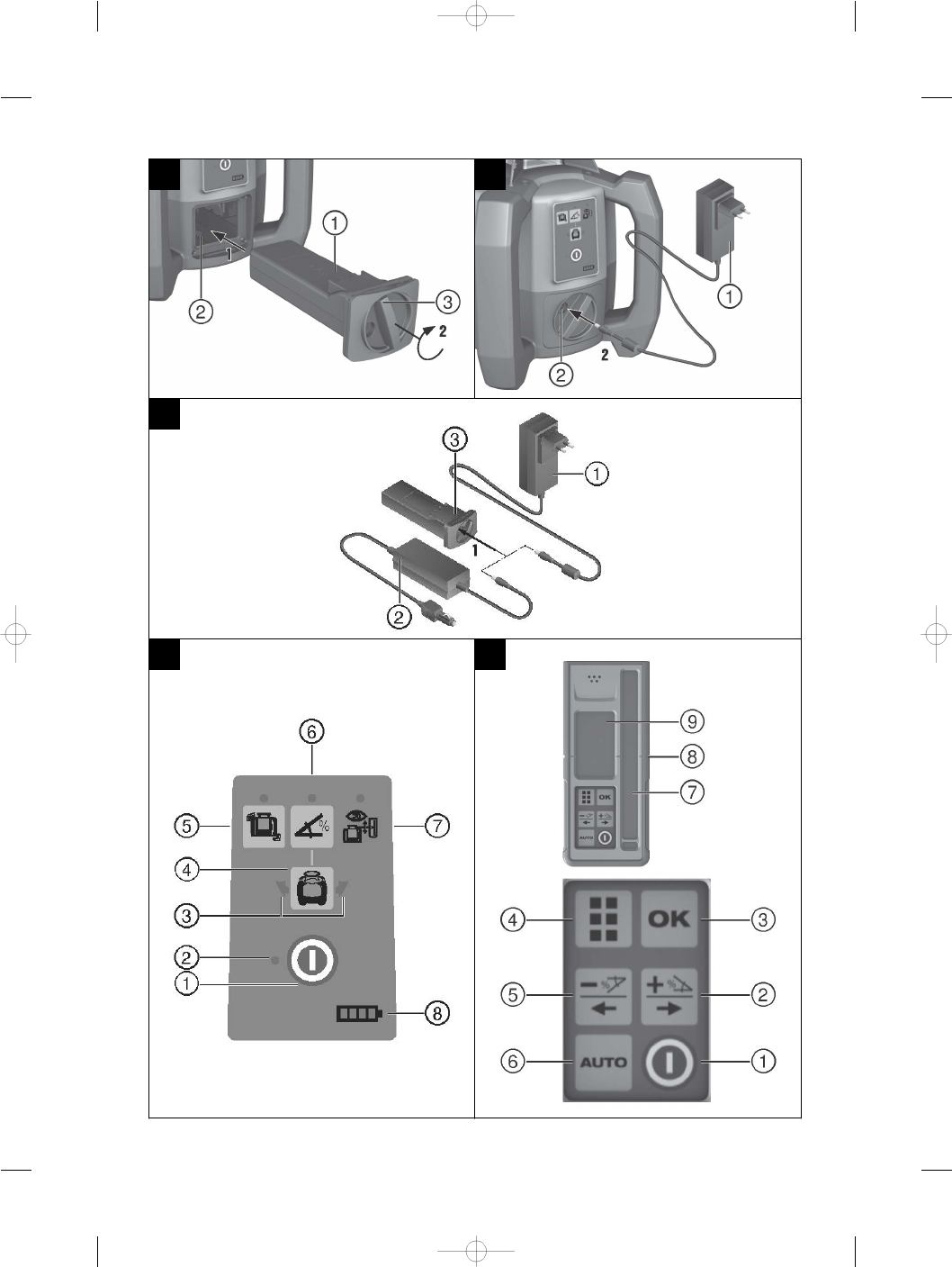
Rotating laser control panel 5
@On/off button
;Auto-leveling LED
=LED arrow for electronic inclination alignment
%Manual electronic inclination alignment key (only in
conjunction with inclined plane mode)
&Shock warning function key and LED
(Inclined plane mode key and LED
)Surveillance mode LED (only with automatic vertical
alignment)
+Battery charge status LED
PRA 300 laser receiver / remote control unit control
panel 6
@On/off button
;Inclination entry key (Plus / Right or Up arrow key)
(with the PRA 90)
=Confirmation button (OK)
%“Menu” button
&Inclination entry key (Minus / Left or Down arrow
key) (with the PRA 90:
(Automatic alignment / surveillance mode key (ver-
tical) (double click)
)Receiving window
+Marking notch
§Display
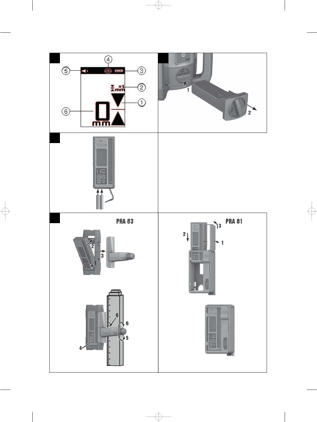
Display on the PRA 300 laser receiver / remote control
unit 7
@Indicator showing position of receiver relative to
height of laser plane
;Indication of accuracy
=Battery status
%Virtual beam shields on/off
&Volume
(Indication of distance from laser plane
en
1
1 General information
1.1 Safety notices and their meaning
DANGER
Draws attention to imminent danger that will lead to
serious bodily injury or fatality.
WARNING
Draws attention to a potentially dangerous situation that
could lead to serious personal injury or fatality.
CAUTION
Draws attention to a potentially dangerous situation that
could lead to slight personal injury or damage to the
equipment or other property.
NOTE
Draws attention to an instruction or other useful informa-
tion.
1.2 Explanation of the pictograms and other
information
Symbols
Read the
operating
instructions
before use.
General
warning
Warning:
caustic
substances
Warning:
electricity
For indoor
use only
Return
materials for
recycling
Do not look
into the
beam.
Warning:
explosive
substances
Locked Unlocked
On the tool
Laser Class 2 product. Do not stare into the beam.
Location of identification data on the tool
The type designation and serial number can be found on
the type identification plate on the tool. Make a note of
this data in your operating instructions and always refer
to it when making an enquiry to your Hilti representative
or service department.
Type:
Generation: 01
Serial no.:
2 Safety instructions
2.1 Basic information concerning safety
In addition to the information relevant to safety given
in each of the sections of these operating instructions,
the following points must be strictly observed at all
times.
2.2 General safety rules
a) Do not render safety devices ineffective and do
not remove information and warning notices.
b) Modification of the tool is not permissible.
c) Stay alert, watch what you are doing and use
common sense when operating the tool. Don’t
use the tool when you are tired or under the influ-
ence of drugs, alcohol or medication. A moment of
inattention while operating tools may result in serious
personal injury.
d) Keep laser tools out of reach of children.
e) Failure to follow the correct procedures when open-
ing the tool may cause emission of laser radiation in
excess of class 2 or, respectively, class 3. Have the
tool repaired only at a Hilti service center.
en
2

f) Do not operate the tool in explosive atmospheres,
such as in the presence of flammable liquids,
gases or dust. Tools and appliances create sparks
which may ignite the dust or fumes.
g) (Statement in accordance with FCC §15.21):
Changes or modifications not expressly approved
by the manufacturer can void the user’s authority to
operate the equipment.
h) Use of setting-up / adjusting devices and equipment
or operating procedures other than those specified in
these instructions may lead to exposure to hazardous
radiation.
i) Check the condition of the tool before use. If the
tool is found to be damaged, have it repaired at a
Hilti service center.
j) Maintain the tool carefully. Check for misalign-
ment or binding of moving parts, breakage of
parts and any other condition that may affect the
tool’s operation. If damaged, have the tool re-
paired before use. Poor maintenance is the cause
of many accidents.
k) The user must check the accuracy of the tool
after it has been dropped or subjected to other
mechanical stresses.
l) Check the tool before using it for important meas-
uring work.
m) Check the accuracy of the measurements several
times during use of the tool.
n) When the tool is brought into a warm environment
from very cold conditions, or vice-versa, allow it
to become acclimatized before use.
o) If mounting on an adapter, check that the tool is
screwed on securely.
p) Keep the laser exit aperture clean to avoid meas-
urement errors.
q) Although the tool is designed for the tough condi-
tions of jobsite use, as with other optical and elec-
tronic instruments (e.g. binoculars, spectacles,
cameras) it should be treated with care.
r) Although the tool is protected to prevent entry
of dampness, it should be wiped dry each time
before being put away in its transport container.
s) Keep the electrical contacts dry (protect from rain
or dampness).
t) Use the AC adapter only for connecting to the AC
supply.
u) Check to ensure that the tool and AC adapter do
not present an obstacle that could lead to a risk
of tripping and personal injury.
v) Ensure that the workplace is well lit.
w) Check the condition of the extension cord and
replace it if damage is found. Do not touch the AC
adapter if the extension cord or AC adapter are
damaged while working. Disconnect the supply
cord plug from the power outlet. Damaged supply
cords or extension cords present a risk of electric
shock.
x) Avoid body contact with earthed or grounded
surfaces, such as pipes, radiators, ranges and
refrigerators. There is an increased risk of electric
shock if your body is earthed or grounded.
y) Do not expose the supply cord to heat, oil or sharp
edges.
z) Never operate the AC adapter when it is dirty or
wet. Dust (especially dust from conductive ma-
terials) or dampness adhering to the surface of
the AC adapter may, under unfavorable condi-
tions, lead to electric shock. Dirty or dusty tools
should thus be checked at a Hilti Service Center
at regular intervals, especially if used frequently
for working on conductive materials.
z) Avoid touching the contacts.
2.2.1 Battery tool use and care
a) Do not expose batteries to high temperatures and
keep them away from fire. This presents a risk of
explosion.
b) Do not disassemble, squash or incinerate batter-
ies and do not subject them to temperatures over
80°C (176°F). This presents a risk of fire, explosion
or injury through contact with caustic substances.
c) Avoid ingress of moisture. Moisture in the interior
of the tool may cause a short circuit and chemical
reactions resulting in burns to the skin or fire.
d) Under abusive conditions, liquid may leak from the
battery. Avoid contact. If contact accidentally oc-
curs, flush with water. In the event of the liquid
coming into contact with the eyes, rinse the eyes
with plenty of water and consult a doctor. Liquid
ejected from the battery may cause irritation or burns.
e) Use only batteries of the type approved for use
with the applicable tool. Use of other batteries or
use of the batteries for purposes for which they are
not intended presents a risk of fire and explosion.
f) Observe the special guidelines applicable to the
transport, storage and use of Li-ion batteries.
g) When not in use, keep the battery and the charger
away from paper clips, coins, keys, nails, screws
or other small metal objects that could cause a
short circuit at the battery terminals or the char-
ging contacts. A short circuit at the battery terminals
or charging contacts could result in personal injury
(burns) or fire.
h) Avoid short circuiting the battery terminals. Check
that the battery terminals and the terminals in the
device are free from foreign objects before inserting
the battery in the device. Short circuiting the bat-
tery terminals presents a risk of fire, explosion and
chemical burns.
i) Do not charge or continue to use damaged bat-
teries (e.g. batteries with cracks, broken parts,
bent or pushed-in and/or pulled-out contacts).
j) Use only the PUA 81 AC adapter, PUA 82 motor
vehicle power adapter or other chargers recom-
mended by the manufacturer to power the tool or
charge the battery. Failure to observe these points
may result in damage to the tool. A charger that is
suitable for a certain type of battery may present a
risk of fire when used with other types of battery.
en
3

2.3 Proper organization of the work area
a) Secure the area in which you are working and
take care to avoid directing the beam towards
other persons or towards yourself when setting
up the tool.
b) Avoid unfavorable body positions when working
from ladders. Make sure you work from a safe
stance and stay in balance at all times.
c) Readings taken in the vicinity of reflective objects or
surfaces, through panes of glass or similar materials
may produce incorrect results.
d) Ensure that the tool is set up on a steady, level
surface (not subject to vibration).
e) Use the tool only within its specified limits.
f) Make sure that your PR 300-HV2S is responding only
to your PRA 300 and not to any other PRA 300 that
may be in use on the jobsite.
g) When working in “charging during operation”
mode, attach the AC adapter in a secure posi-
tion, e.g. on a tripod.
h) Use of products for applications different from those
intended could result in hazardous situations. Use
the product and its accessories etc. in accord-
ance with these instructions and in the manner
intended for the particular type of product. Take
the working conditions and the work to be per-
formed into account.
i) Use of the telescopic staff in the vicinity of over-
head high voltage cables is not permissible.
2.3.1 Electromagnetic compatibility
Although the tool complies with the strict requirements
of the applicable directives, Hilti cannot entirely rule out
the possibility of the tool being subject to interference
caused by powerful electromagnetic radiation, leading
to incorrect operation. Check the accuracy of the tool
by taking measurements by other means when working
under such conditions or if you are unsure. Likewise, Hilti
cannot rule out the possibility of interference with other
devices (e.g. aircraft navigation equipment).
2.3.2 Laser classification for Laser Class 2
products
According to the version purchased, the tool complies
with Laser Class 2 as per IEC60825-1:2007 / EN60825-
1:2007. This tool may be used without need for further
protective measures. Nevertheless, as with the sun, one
should not look directly into sources of bright light. In the
event of direct eye contact with the laser beam, close
your eyes and move your head out of the path of the laser
beam. Do not direct the laser beam toward persons.
3 Description
3.1 Use of the product as directed
The Hilti PR 300-HV2S is a rotating laser tool with a visible rotating laser beam and a reference beam set at 90° to the
main beam. The rotating laser can be used vertically, horizontally and for inclinations in one or two planes.
The tool is designed to be used to determine, transfer and check levels, verticals, slopes and right angles. Examples of
its uses are: transferring datums and height marks, determining right angles for walls, vertical alignment on reference
points and setting out slopes.
The tool is designed for professional use and may be operated, serviced and maintained only by trained, authorized
personnel. This personnel must be informed of any special hazards that may be encountered. The tool and its ancillary
equipment may present hazards when used incorrectly by untrained personnel or when used not as directed.
Hilti supplies various accessories which allow the tool to be used with maximum efficiency.
To avoid the risk of injury, use only genuine Hilti accessories and insert tools.
3.2 Features
The tool makes it possible for a single person to level or align in any plane quickly and with great accuracy.
Leveling takes place automatically after the tool is switched on. The laser beam is activated after the tool has leveled
itself.
LEDs indicate the current operating status.
The tool is powered by a rechargeable Li‑ion battery which can be charged while the tool is in operation.
3.3 Combined use of the PRA 300 remote control / laser receiver
The PRA 300 is a combined remote control unit and laser receiver. It can be used to control the PR 300-HV2S rotating
laser over great distances. The PRA 300 also serves as a laser receiver and can thus be used to detect and indicate
the laser beam at great distance.
3.4 Digital distance measurement display
The laser receiver displays digitally the distance between the laser plane and the marking notch. This allows the user to
determine the exact position of the receiver relative to the laser plane, with millimeter accuracy, in a single operation.
en
4

3.5 Automatic alignment and surveillance
Using the PR 300-HV2S and the PRA 300, a single person can align the laser plane automatically with a certain point
with great accuracy. The tool detects the applicable alignment (horizontal, vertical or inclined) automatically and uses
the automatic alignment function accordingly (horizontal with the PRA 90 plus inclination) or automatic alignment with
subsequent monitoring of the plane (vertical). With the aid of the PRA 300, the surveillance function checks alignment
of the laser plane at regular intervals in order to avoid possible deviations due to temperature fluctuations, wind or
similar. The surveillance function can be deactivated.
3.6 Digital inclination display
The digital inclination display is capable of indicating an inclination of up to 25% when the PR 300-HV2S is operating
in inclined mode. This makes it possible to set out and check slopes without having to make any calculations. Manual
electronic inclination alignment allows optimum inclination accuracy.
3.7 Shock warning
The shock warning function is activated two minutes after the tool has leveled itself after switching on. If a key is
pressed within these two minutes, the two-minute delay begins again. The tool switches to warning mode if it is
brought out of level while in operation (due to vibration or an impact); all LEDs begin to blink and the laser switches
off (the head stops rotating).
3.8 Automatic cut-out
The laser does not switch on and all LEDs blink if the tool is set up outside its self-leveling range (±16° X-axis, ±10°
Y-axis) or if movement is blocked mechanically.
The tool can be set up on a tripod with a 5/8" thread or stood directly on some other steady surface (free of vibration).
When automatic leveling is activated for one or both axes, the built-in servo system ensures that the specified accuracy
is maintained. The tool switches itself off when automatic leveling cannot be achieved (tool set up outside its leveling
range or physical impediment of the mechanism) or when knocked off level (see “Shock warning” section).
NOTE
If the correct level cannot be achieved, the laser switches itself off and all LEDs blink.
3.9 Items supplied
1 PR 300-HV2S rotating laser
1 PRA 300 laser receiver / remote control unit
1 PRA 83 laser receiver holder
1 Operating instructions
1 PRA 84 Li-Ion battery
1 PUA 81 AC adapter
2 Batteries (size AA cells)
2 Manufacturer’s certificates
1 Hilti toolbox
NOTE
Accessories are available from your Hilti Center or can be ordered online at www.hilti.com.
3.10 Operating status indicators
The tool is equipped with the following operating status indicators: Auto-leveling LED, battery charge status LED,
shock warning function deactivation LED, inclined plane mode LED, surveillance mode LED and electronic inclination
alignment LED.
en
5

3.11 LED indicators on the PR 300-HV2S rotating laser
Auto-leveling LED The green LED blinks. The tool is in the leveling phase.
The green LED lights con-
stantly.
The tool has leveled itself / is operating
normally.
Shock warning deactivation LED The orange LED lights con-
stantly.
The shock warning function is deactiv-
ated.
Inclined plane mode LED The orange LED blinks. Alignment in the sloping plane.
The orange LED lights con-
stantly.
Inclined plane mode is active.
Surveillance mode LED The orange LED lights con-
stantly.
The tool is aligning the laser plane with
the reference point (PRA 300).
The orange LED blinks. The tool is in surveillance mode. Align-
ment with the reference point (PRA 300)
is correct.
Electronic inclination alignment LED The orange LED arrows blink. The tool is in electronic inclination align-
ment mode, the PRA 300 receives no
laser beam.
Both orange LED arrows light
constantly.
The tool is correctly aligned with the
PRA 300.
The orange LED arrow on the
left lights.
The tool must be rotated in a clockwise
direction.
The orange LED arrow on the
right lights.
The tool must be rotated in a counter-
clockwise direction.
All LEDs All LEDs blink. The tool has been bumped or is indicat-
ing a fault.
3.12 Charge state of the Li-ion battery while the tool is in operation
LEDs light constantly LEDs blink Charge status C
LED 1, 2, 3, 4 -C ≧ 75 %
LED 1, 2, 3 -50 % ≦ C < 75 %
LED 1, 2 -25 % ≦ C < 50 %
LED 1 -10 % ≦ C < 25 %
-LED 1 C < 10 %
3.13 Charge state of the Li‑ion battery while charging in the tool
LEDs light constantly LEDs blink Charge status C
LED 1, 2, 3, 4 -C = 100 %
LED 1, 2, 3 LED 4 75 % ≦ C < 100 %
LED 1, 2 LED 3 50 % ≦ C < 75 %
LED 1 LED 2 25 % ≦ C < 50 %
-LED 1 C < 25 %
3.14 Charging activity display on the Li-ion battery while charging the battery outside the tool
If the red LED lights constantly, the battery is being charged.
If the red charging activity LED does not light, then either the charging operation is complete or the charger is providing
no current.
en
6

4 Technical data
Right of technical changes reserved.
PR 300-HV2S
Receiving range (diameter) Typical distance with PRA 300: 2…600 m
Range of remote control (circle diameter) Typical distance with PRA 300, In the open field,
without external influences: 0…240 m
Accuracy1at 10 m (33 ft): ± 0.5 mm (0.02 in)
Plumb beam Continuous, perpendicular to the plane of rotation
Laser class Class 2, 620-690 nm; < 1 mW (EN 60825-1:2007 / IEC
60825-1:2007); Maximum power < 4.85 mW at ≧ 300
r.p.m.
Speed of rotation 600/min, 1,000/min (during the automatic alignment
procedure)
Inclination range With the tool already inclined: ≤ 25%
Self-leveling range ±16° X-axis, ±10° Y-axis
Power source 7.2V/ 4.5 Ah Li‑ion battery
Battery life Temperature +25°C, Li‑ion battery: ≥ 25 h
Operating temperature range -20…+50°C
Storage temperature range (dry) -25…+60°C
Protection class IP 66 (in accordance with IEC 60529); Not in “charging
during operation” mode
Tripod thread ⁵⁄₈" x 18
Weight (incl. PRA 84) 2.5 kg
Drop test height21.5 m
1Influences such as particularly high temperature fluctuations, dampness, shock, dropping, etc. can affect accuracy. Unless stated
otherwise, the tool was adjusted or calibrated under standard ambient conditions (MIL-STD-810G).
2The drop test was carried out from a tripod, dropping onto flat concrete under standard ambient conditions (MIL-STD-810G).
PRA 300
Detection range (area diameter) With the PR 300-HV2S (typical): 2…600 m
Signal tone generator 3 volume levels plus mute setting
Liquid-crystal display On both sides
Indicator range, distance from zero ± 52 mm (± 2 in)
Laser plane display range ± 1.0 mm (0.04 in)
Length of the detection area 120 mm
Casing top edge center indicator 75 mm
Marking notches On both sides
Time without detection before automatic power off 15 min
Weight (including batteries) 0.25 kg
Power source 2 AA batteries
Battery life Temperature +20°C: Approx. 40 h (depending on the
quality of the alkaline batteries used)
Operating temperature range -20…+50°C
Storage temperature range -25…+60°C
1The drop test was carried out using the PRA 83 receiver holder, dropped onto flat concrete under standard ambient conditions
(MIL-STD-810G).
en
7

Protection class IP 66 (in accordance with IEC 60529), except battery
compartment
Drop test height12 m
1The drop test was carried out using the PRA 83 receiver holder, dropped onto flat concrete under standard ambient conditions
(MIL-STD-810G).
PRA 84 Li‑Ion battery
Rated voltage (normal mode) 7.2 V
Maximum voltage (during operation or during charging
while in operation)
13 V
Rated current 180 mA
Charging time Temperature +32°C: 2 h 10 min (battery 80 % charged)
Operating temperature range -20…+50°C
Storage temperature range (dry) -25…+60°C
Charging temperature range (also for charging during
operation)
+0…+40°C
Weight 0.3 kg
PUA 81 AC adapter
AC supply 115…230 V
AC frequency 47…63 Hz
Rated power 36 W
Rated voltage 12 V
Operating temperature range +0…+40°C
Storage temperature range (dry) -25…+60°C
Weight 0.23 kg
5 Before use
NOTE
The tool may be powered only by a Hilti PRA 84 or PRA
84G battery.
5.1 Inserting the battery 2
1. Slide the battery into the tool.
2. Turn the catch in a clockwise direction until the
“locked” symbol appears.
5.2 Removing the battery 8
1. Turn the catch in a counter-clockwise direction until
the “unlocked” symbol appears.
2. Remove the battery from the tool.
5.3 Charging the battery
5.3.1 Charging a battery for the first time
Charge the battery fully before using it for the first time.
NOTE
Make sure the system to be charged is standing securely.
5.3.2 Recharging a battery
1. Check that the outer surfaces of the battery are
clean and dry.
2. Insert the battery in the tool.
NOTE Li‑ion batteries are ready for use at any time,
even when only partly charged.
Charging progress is indicated by the LEDs when
the tool is switched on.
5.4 Options for charging the battery
NOTE
Make sure that the recommended temperature range is
observed when charging (0 to 40°C / 32-104°F).
DANGER
The PUA 81 AC adapter is for indoor use only. Avoid
ingress of moisture.
en
8
5.4.1 Charging the battery in the tool 4
1. Insert the battery in the battery compartment (see
5.1).
2. Rotate the socket cover until the charging socket on
the battery becomes visible.
3. Plug the cord from the AC adapter or motor vehicle
power adapter into the battery.
The battery will be charged.
4. Switch the tool on in order to display the charging
status while charging is in progress.
5.4.2 Charging the battery when not in the tool 5
1. Remove the battery (see 5.2).
2. Connect the cord from the AC adapter or the motor
vehicle power adapter to the battery.
The red LED on the battery indicates charging activ-
ity.
5.4.3 Charging the battery while the tool is in
operation
DANGER
Operation in “charging during operation” mode is not
permissible for outdoor use or in damp surroundings.
1. Rotate the socket cover until the charging socket on
the battery becomes visible.
2. Plug the cord from the AC adapter into the battery.
The tool continues to operate while charging and
battery charging status is indicated by the LEDs on
the tool.
5.5 Switching on the rotating laser
Press the on/off button .
NOTE
After switching on, the tool begins to level itself automat-
ically. After completion of the leveling process, the laser
beam is switched on and begins to rotate in the normal
direction.
5.6 LED indicators
See section “LED indicators on the PR 300-HV2S rotating
laser” for a description.
5.7 Inserting batteries in the PRA 300 9
DANGER
Do not use damaged batteries.
DANGER
Do not mix old and new batteries. Do not mix batteries of
different makes or types.
NOTE
The PRA 300 may be powered only by batteries manu-
factured in accordance with the applicable international
standards.
1. Open the laser receiver battery compartment.
2. Insert the batteries in the laser receiver.
NOTE Check to ensure correct polarity when insert-
ing the batteries.
3. Close the battery compartment cover.
5.8 Pairing
The rotating laser and the remote control / laser receiver
are already paired when supplied. Additional laser receiv-
ers of the same type or PRA 90 automatic tripods are not
ready for use until they have been paired. The rotating
laser and these accessories must be paired before they
can be used together. Pairing tools and devices means
that they are explicitly assigned to each other. The rotat-
ing laser and the PRA 90 automatic tripod then receive
only signals from the remote control units / laser receivers
with which they have been paired. Pairing allows devices
to be used close to other rotating lasers without the risk
that their settings will be altered by these other lasers.
5.8.1 Pairing the rotating laser and the laser
receiver
1. Press the on/off buttons on the rotating laser
and laser receiver simultaneously and keep them
pressed for at least 3 seconds.
Successful pairing is indicated by a signal tone
emitted by the laser receiver and all LEDs blinking
on the rotating laser. At the same time, the symbol
shown above appears briefly in the laser receiver
display. The rotating laser and the receiver switch
off automatically after pairing.
2. Switch the paired devices on again.
5.8.2 Pairing the PRA 90 tripod and the receiver
1. Press the on/off buttons on the PRA 90 automatic
tripod and laser receiver simultaneously and keep
them pressed for at least 3 seconds.
Successful pairing is indicated by a signal tone
emitted by the laser receiver and all LEDs blinking
on the rotating laser. At the same time, the symbol
shown above appears briefly in the laser receiver
display. The rotating laser and the receiver switch
off automatically after pairing.
2. Switch the paired devices on again.
The rotating laser with the tripod is shown in the
display on the laser receiver.
en
9
6 Operation
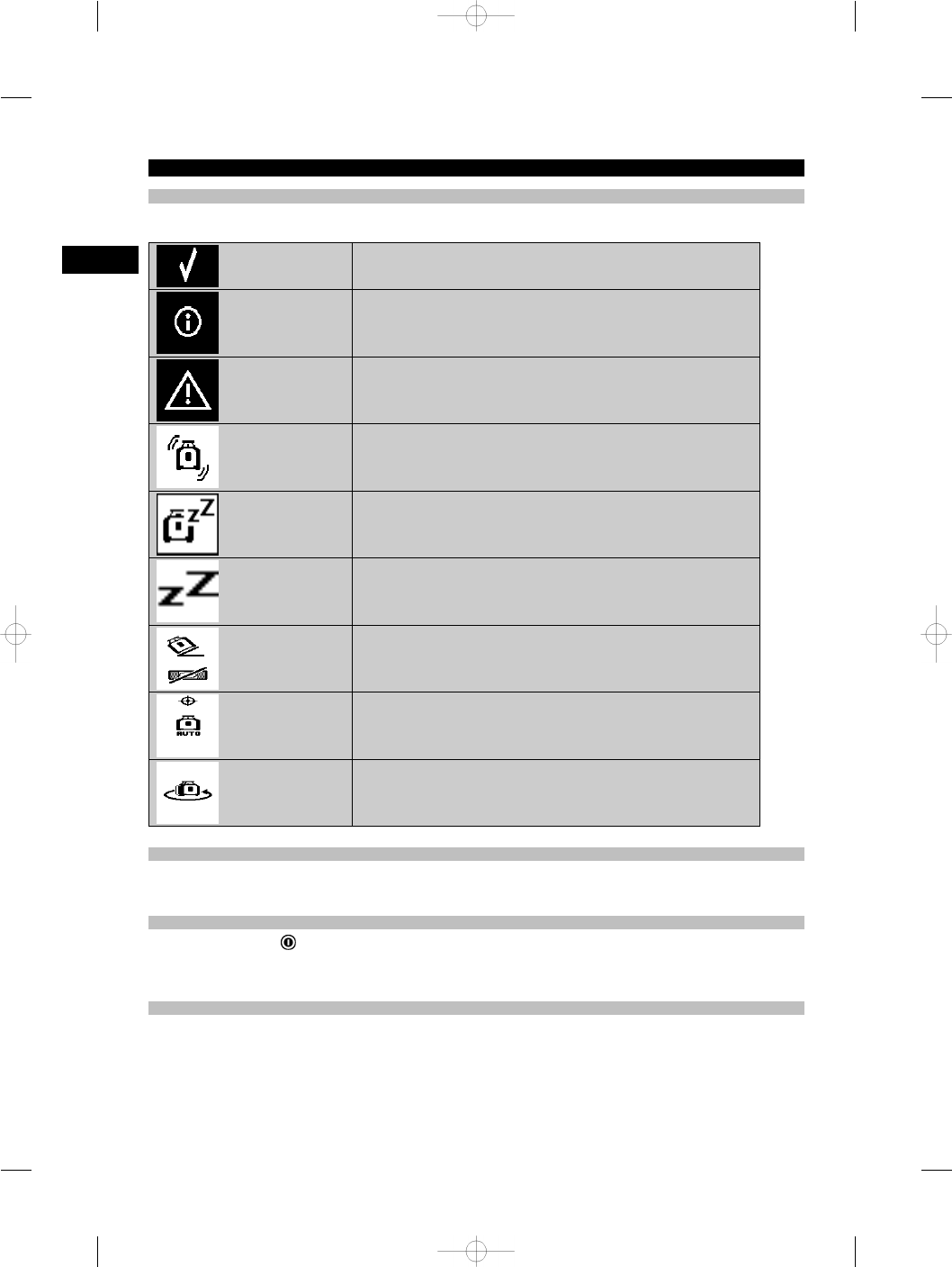
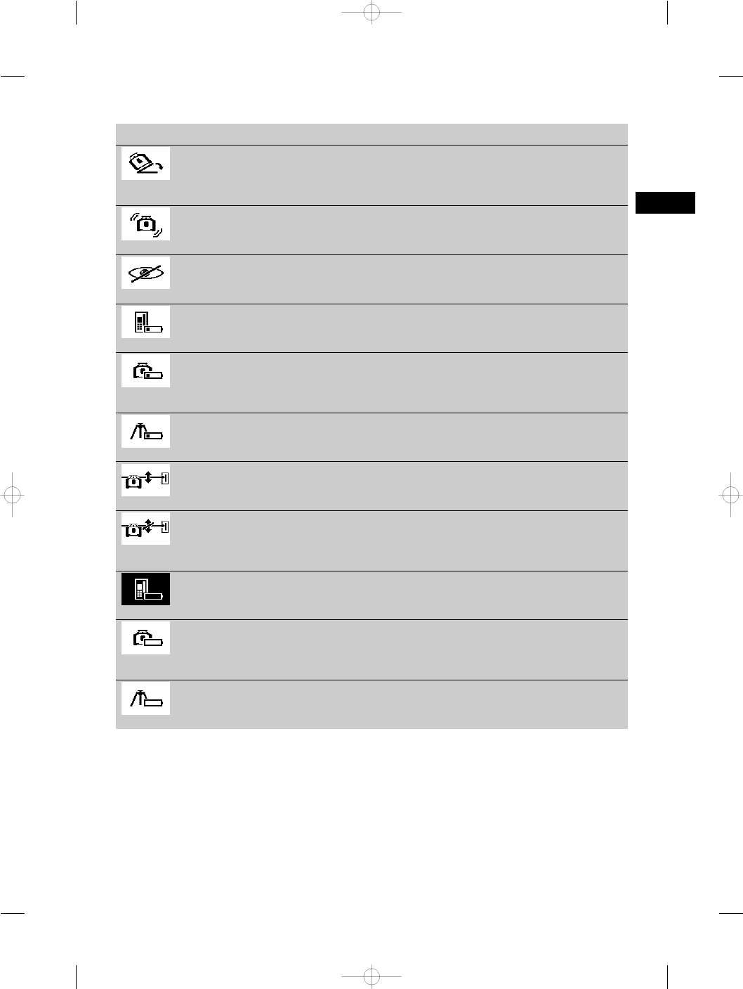
6.1 Overview of general symbols
Overview of general symbols
General symbols
Activity successfully completed.
Information
Warning
Shock warning is activated
Sleep mode is activated
The rotating laser is in sleep mode
Inclined plane mode is activated
Automatic electronic alignment is activated
Manual alignment
6.2 Checking the tool
Check the accuracy of the tool before using it for important tasks, especially if it has been dropped or subjected to
unusual influences or impacts etc. (see 7.6).
6.3 Switching the tool on
Press the on/off button .
NOTE
After switching on, the tool begins to level itself automatically.
6.4 Working with the PRA 300 laser receiver / remote control unit
The PRA 300 is a combined laser receiver and remote control unit. The remote control makes working with the rotating
laser more convenient and is required in order to make use of certain functions. The laser beam is indicated by visual
and audible signals.
en
10
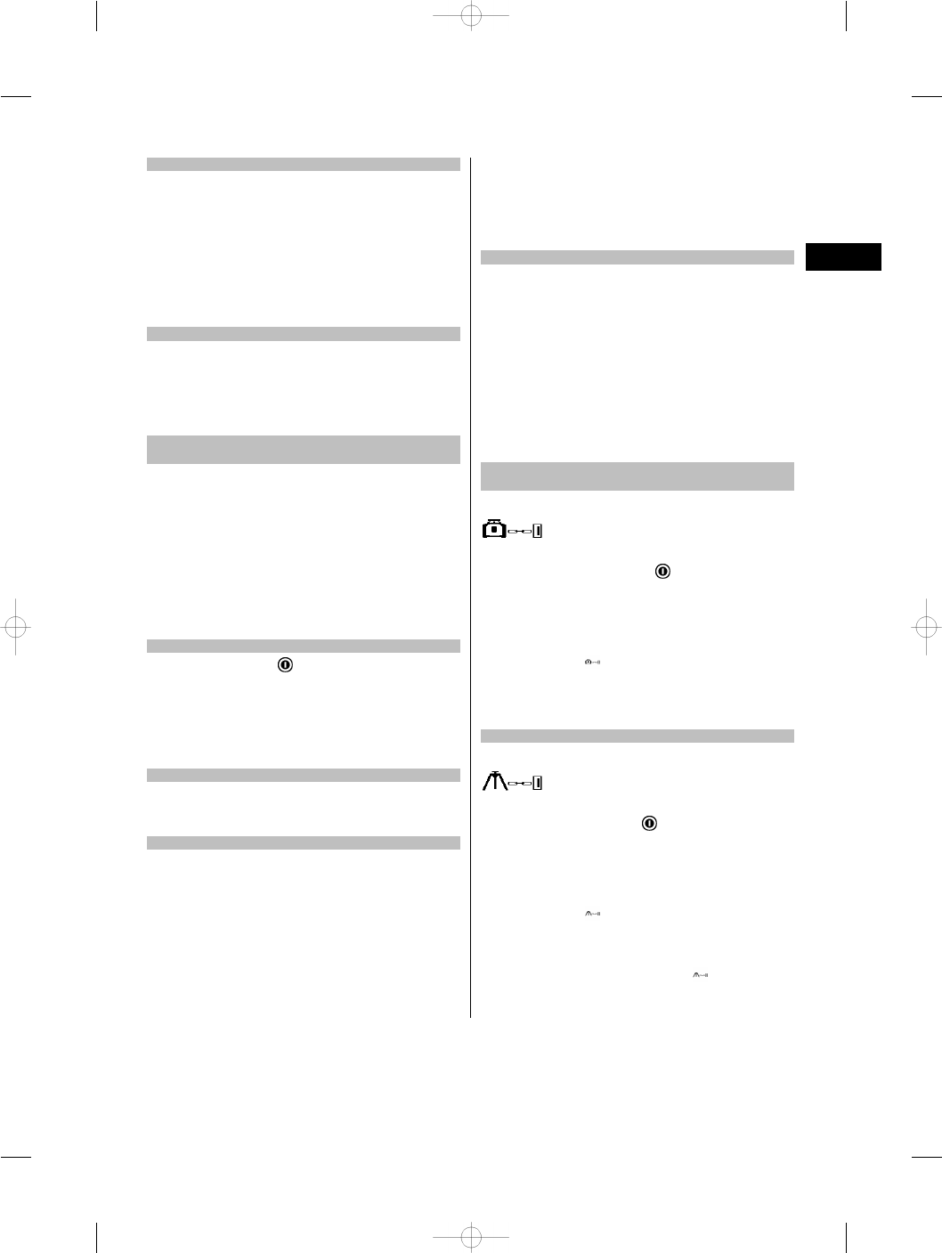
6.4.1 Using the PRA 300 laser receiver as a hand-held tool
1. Press the on/off button .
NOTE If the receiver was switched on before the PR 300 rotating laser was started, a laser beam will not yet be
shown in the receiver’s display.
2. Hold the laser receiver with the detection area directly in the plane of the rotating laser beam.
6.4.2 Working with the laser receiver in the PRA 83 receiver holder
1. Push the receiver into the rubber sleeve of the PRA 83 at an angle until it fully encloses the receiver. Take care to
ensure that the detection area and the keys are facing the front.
2. Fit the receiver, complete with the rubber sleeve, onto the grip section. The cover and grip section are joined
together by the magnetic holder.
3. Switch the receiver on by pressing the on/off button .
4. Turn the rotating grip to the open position.
5. Secure the PRA 83 receiver holder on the telescopic staff or leveling staff by tightening the clamping knob.
6. Hold the laser receiver with the detection area directly in the plane of the rotating laser beam.
6.4.3 Working with the PRA 81 height transfer device
1. Open the catch on the PRA 81.
2. Insert the laser receiver in the PRA 81 height transfer device.
3. Close the catch on the PRA 81.
4. Switch the laser receiver on by pressing the on/off button .
5. Hold the laser receiver with the detection area directly in the plane of the rotating laser beam.
6. Position the laser receiver so that the distance display shows “0”.
7. Use the measuring tape to measure the desired distance.
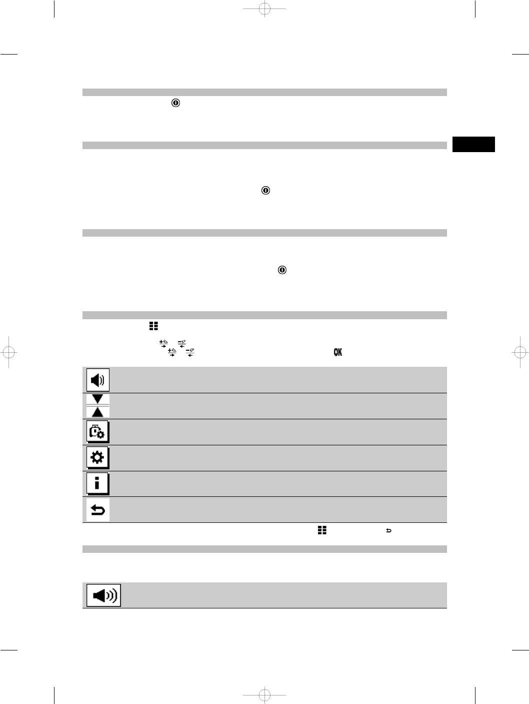
6.5 Menu options on the PRA 300 laser receiver / remote control unit
1. The “Menu” key may be pressed at any time during operation.
The menu then appears in the display.
2. Use the arrow keys or , as required, to select the individual items from the menu.
NOTE The arrow keys or let you select the various settings. Press the key to save the settings you have
selected.
Volume level
Units
System setup
Tool setting
Information
Back
3. You can leave the menu again at any time by pressing the “Menu” key or the “Back” key .
6.5.1 Setting the volume level
The laser receiver is set to “Normal” volume every time it is switched on. The volume can be adjusted by way of the
“Volume” function in the menu. One of four settings can be selected: “Low”, “Normal”, “High” or “Off”. After making a
selection you are returned automatically to the normal operating mode.
Volume high
en
11
Volume normal
Volume low
Volume off
Press the “Back” key if you wish to return to the menu.
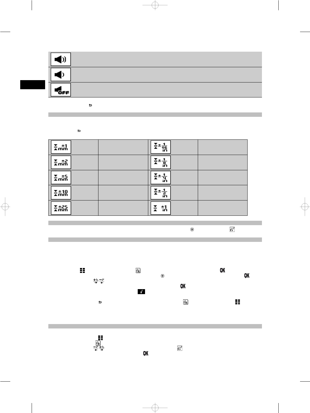
6.5.2 Setting the units
Using the units function from the menu you can set the desired accuracy of the digital display in millimeters or inches.
After making each selection you are returned automatically to the normal operating mode or, alternatively, pressing
the “Back” key will take you back to the menu.
Units
1 mm ¹⁄₁₆"
2 mm ¹⁄₈"
5 mm ¹⁄₄"
10 mm ¹⁄₂"
25 mm 1"
6.5.3 System setup
The following items appear in the menu: “Activate / deactivate beam shields” and “Sleep mode” .
6.5.3.1 Activating/deactivating the beam shields
The laser beam from the PR 300-HV2S can be shut off at one or more sides of the tool. This feature is useful when
you are using several laser tools simultaneously on the jobsite and it is necessary to prevent reception of the beam
from more than one laser tool. The laser plane is divided into four quadrants. These are marked on the casing of the
tool and can be set as follows:
1. In the menu , select the system settings and confirm your selection by pressing the key.
2. Select the “Activate / deactivate beam shields” function and confirm your selection by pressing the key.
3. Use the arrow keys to navigate to the correct quadrant.
4. Activate / deactivate the desired quadrants by pressing the OK key .
5. Confirm this setting by pressing the OK key .
If the quadrant is visible its status is “On”. If the quadrant is not visible its status is “Off”.
6. Press the “Back” key to return to the “System setup” menu item or press the “Menu” key to return to
normal operating mode.
NOTE Settings that affect the rotating laser only become effective when the rotating laser is switched on and a
wireless connection has been established.
6.5.3.2 Activating / deactivating sleep mode
The PR 300-HV2S saves power when in sleep mode. The laser is switched off, thereby extending battery life.
1. Press the “Menu” key on the PRA 300.
2. Select system setup .
3. Use the arrow keys to navigate to the option “Sleep mode” .
4. Confirm your selection by pressing the OK key .
en
12
5. Activate / deactivate sleep mode by pressing the OK key .
NOTE All settings remain saved.
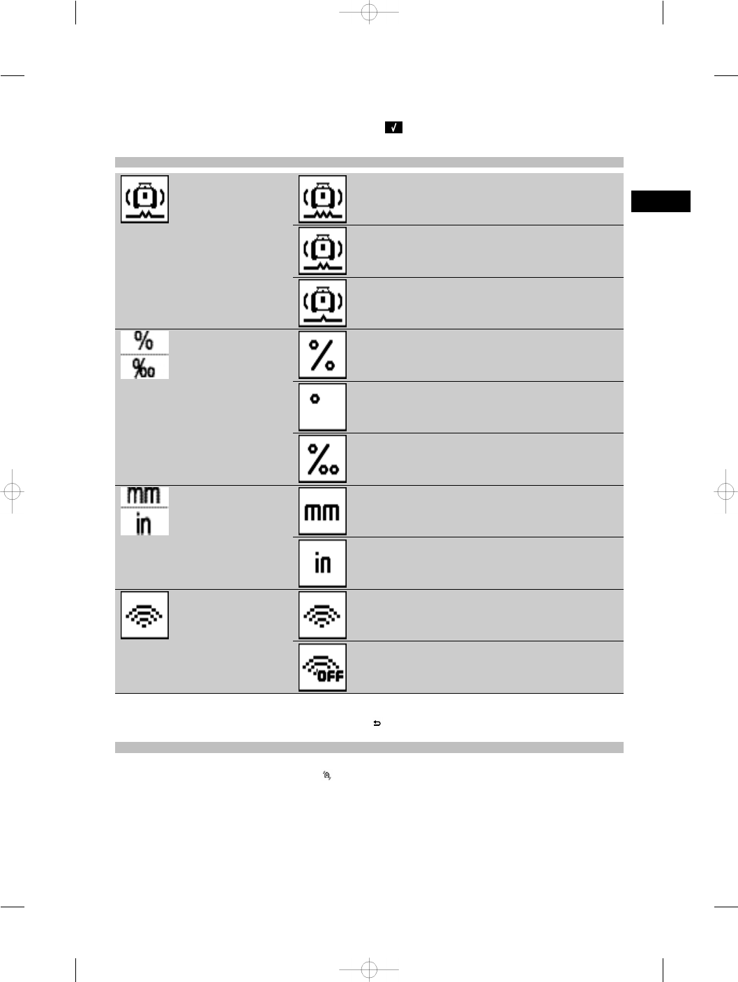
6.5.4 Tool settings
Shock warning sensitivity
High vibration, low sensitivity to shock
Medium
Low
Inclined plane mode units
Percent
Degrees
Thousandths
Units
Millimeters
Inches
Wireless connection
On
Off
Settings that affect the rotating laser only become effective when the rotating laser is switched on and a wireless
connection has been established. Pressing the “Back” key takes you back to the main menu.
6.5.4.1 Deactivating the shock warning function
1. Switch the rotating laser on (see 6.3).
2. Press the “Deactivate shock warning” key .
The shock warning deactivation LED lights constantly, indicating that the function has been deactivated.
If the shock warning function is deactivated, the tool no longer reacts to shock (i.e. when bumped or shaken).
3. To return to standard operating mode, switch the tool off and then switch it back on again.
en
13
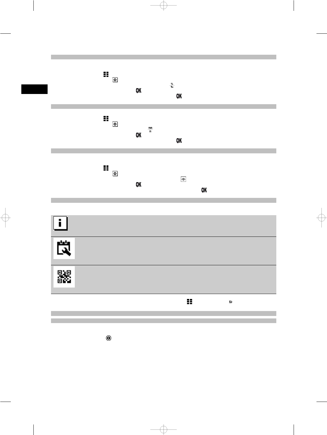
6.5.4.2 Inclined plane mode units
Under “Inclined plane mode units” the units to be used when entering an inclination can be set to percent, degrees or
thousandths.
1. Press the “Menu” key on the PRA 300.
2. Choose the “Settings” key .
3. Use the arrow keys to select “Inclined plane mode units” .
4. Confirm your selection by pressing the key.
5. Choose the correct units and activate these by pressing the key.
6.5.4.3 Units
This item in the menu lets you choose between metric and imperial units.
1. Press the “Menu” key on the PRA 300.
2. Choose the “Settings” key .
3. Press one of the arrow keys to select “Units” .
4. Confirm your selection by pressing the key.
5. Choose the correct units and activate these by pressing the key.
6.5.4.4 Wireless connection
If necessary, you can deactivate the receiver’s wireless connection and then use the receiver / remote control unit
simply as a receiver.
1. Press the “Menu” key on the PRA 300.
2. Choose the “Settings” key .
3. Use the arrow keys to select the “Wireless connection” option .
4. Confirm your selection by pressing the key.
5. Choose the correct wireless connection and activate this by pressing the key.
6.5.5 Information
When this menu item is selected you have the following options:
Software version
The software version of the tool, receiver and PRA 90 can be viewed
here.
Date of last calibration
The date of the last calibration can be viewed here.
QR code
The QR code, which can be scanned with a smartphone, is linked to an-
imation videos that explain how to operate the system.
You can leave the menu again at any time by pressing the “Menu” key or the “Back” key .
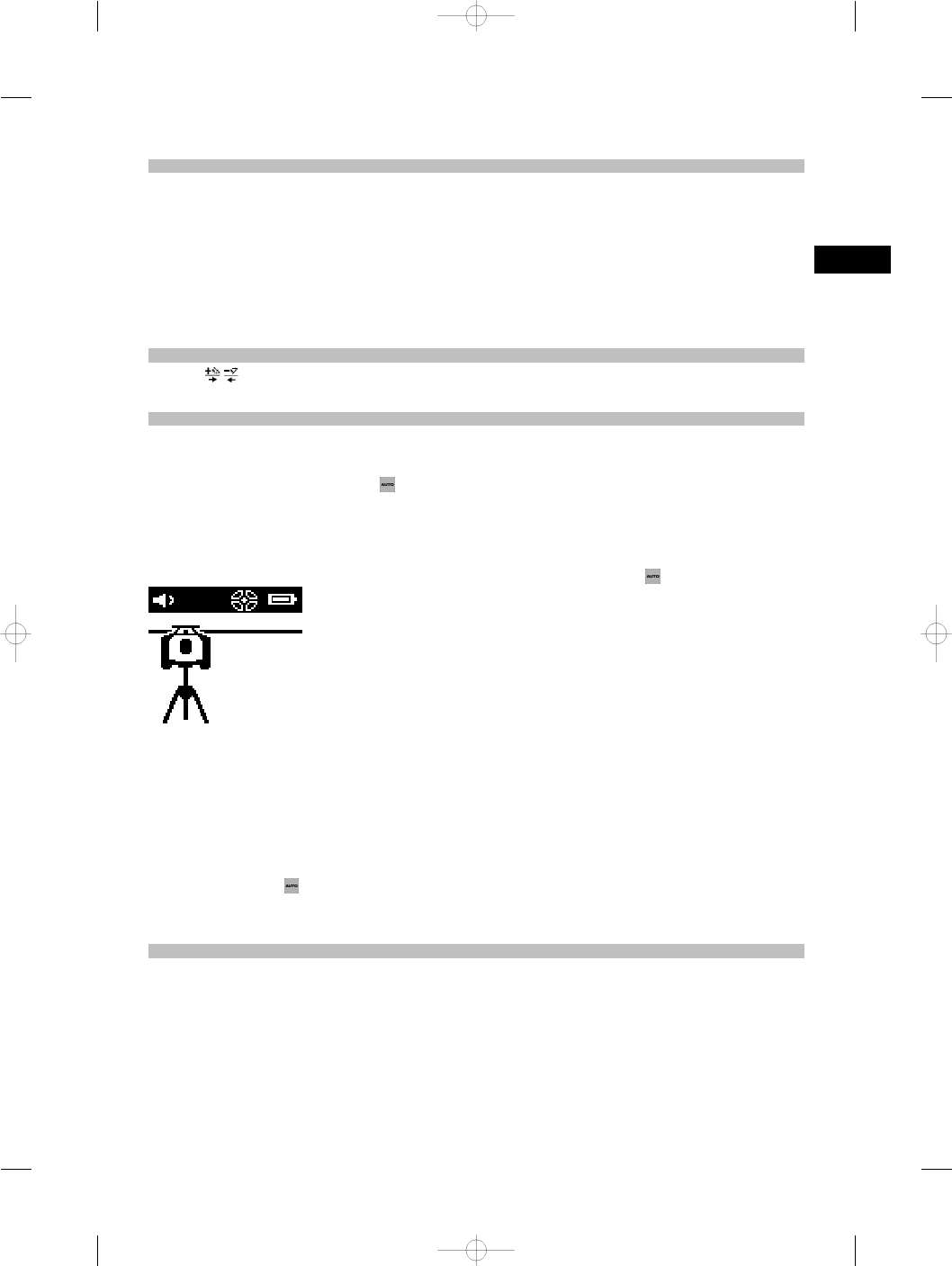
6.6 Working in the horizontal plane
6.6.1 Setting up
1. Set up the tool in a suitable position for the application, e.g. on a tripod. Alternatively, the rotating laser may be
mounted on a wall bracket. The angle of inclination of the surface on which it stands should not exceed ± 5°.
2. Press the on/off button .
The “auto leveling” LED blinks green and the leveling status is shown in the display on the laser receiver.
The laser switches on, the beam begins to rotate and the “auto leveling” LED lights as soon as the tool has
leveled itself.
en
14
6.6.2 Alignment using the PRA 90 automatic tripod
NOTE
This function is available only with the PRA 90 automatic tripod.
When used for the first time, the PRA 300 laser receiver must be paired with the tripod (see 6.9.2).
With the optional PRA 90 automatic tripod you can set the height of the laser plane to the desired level manually or
automatically.
1. Mount the tool on the PRA 90 automatic tripod.
2. Switch on the rotating laser, the automatic tripod and the laser receiver. Set the height of the laser plane manually
(see 6.6.2.1) or automatically (see 6.6.2.2).
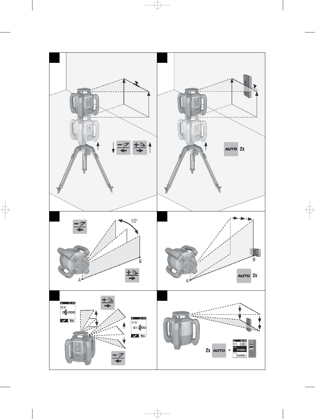
6.6.2.1 Manual alignment 6
Press the keys on the laser receiver or the arrow keys on the PRA 90 to shift the horizontal plane up or down
(parallel).
6.6.2.2 Automatic alignment 6
1. Hold the laser receiver at the desired height with the detection area facing the PRA 90 control panel. Hold the
laser receiver still while alignment is taking place and take care to ensure that the line of sight between the laser
receiver and the tool is not obstructed.
2. Press the “Automatic alignment” key on the laser receiver twice in quick succession (double-click). Double-click
the key again to complete the procedure.
The laser plane alignment process is then started, i.e. the tripod elevates or lowers itself to the required height. A
constant signal tone is emitted while this is taking place. As soon as the laser beam strikes the detection area of
the laser receiver, the beam moves to the position of the marking notch (reference plane).
After the position has been reached and the rotating laser has leveled itself, a signal tone with a duration of 5
seconds indicates that the process is complete. The “Automatic alignment” symbol is then no longer shown.
3. Check the height settings in the display.
4. Remove the laser receiver.
NOTE If the automatic alignment process was not successful, short signal tones are emitted and the “Automatic
alignment” symbol disappears.
NOTE A warning is also displayed on the laser receiver indicating that the receiver is outside the possible
receiving area.
6.7 Working in the vertical plane
1. When working in the vertical plane, mount the tool on a suitable tripod, facade adapter, batter board adapter or
wall bracket, with the control panel facing upwards. Alternatively, the tool can be stood on the rubber feet on the
rear grips.
NOTE The best wireless connection with the PRA 300 is provided by the side of the tool to the right of the control
panel.
NOTE In order to ensure that the tool’s specified accuracy can be maintained, make sure that it is set up on a
level surface or mounted sufficiently level on the tripod or other accessory.
2. Use the visual sighting method (front and rear sights) to align the rotating laser in the desired direction.
en
15
3. Press the on/off button .
After the tool has leveled itself automatically, it projects a stationary laser beam vertically downwards. This
projected point is a reference point (not a plumb point) and can be used to help position the tool.
4. Align the tool so that the projected laser point coincides exactly with a reference point (e.g. nail on a batter board).
5. Now line up the laser plane with the second reference point manually (see 6.7.1) or automatically (see 6.7.2).
The laser begins to rotate automatically as soon as you begin the alignment operation.
6.7.1 Manual alignment 6
1. Press the arrow keys on the laser receiver in order to align the vertical plane manually.
6.7.2 Automatic alignment and surveillance 6
1. Mount or hold the laser receiver with the marking notch at the desired alignment point and facing the rotating
laser.
2. Double-click the “Automatic alignment” key . Double-click the key again to complete the procedure.
The laser plane alignment procedure then begins. A constant signal tone is emitted while this is taking place.
The direction of the search can be changed by pressing the “Automatic alignment” key once.
As soon as the laser beam strikes the detection area of the laser receiver, the beam moves to the position of the
marking notch (reference plane).
Once the position is reached (i.e. the marking notch is found), a signal tone with a duration of 5 seconds indicates
that the process is complete.
The laser receiver switches automatically to surveillance mode and checks at regular intervals whether the laser
plane has shifted. If it is found to have shifted, the laser plane will be readjusted to the original marking notch as
far as possible. If the marking plane is outside the leveling range of ±5°, direct line of sight between the rotating
laser and the laser receiver is obstructed for a long period or the alignment process is not completed successfully
within a time of 2 minutes, then short signal tones are emitted, the laser stops rotating and the “Automatic
alignment” symbol disappears. This indicates cancellation of the automatic alignment process.
3. After the automatic alignment process is completed and, instead of leaving the receiver in position, you wish to
use the device again as a receiver, you can leave surveillance mode again by pressing the “Automatic alignment”
key twice in quick succession (double click).
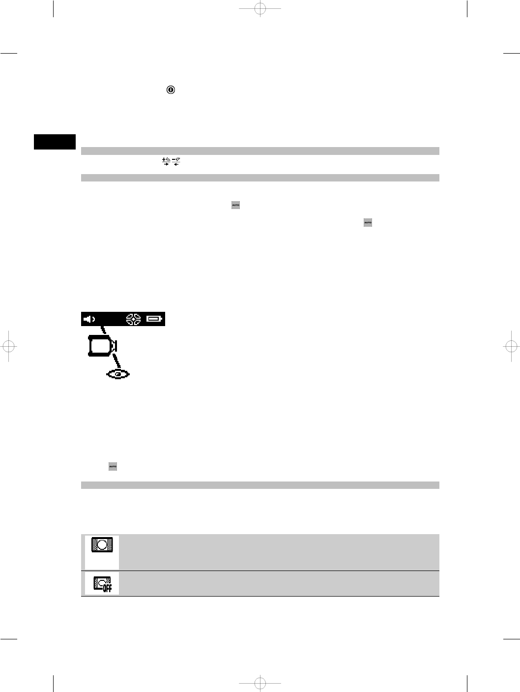
6.8 Working with slopes
NOTE
If the tool measures a change in temperature of more than 10 degrees, laser rotation stops for about 40 seconds.
During this time the tool corrects all errors that may have been caused by the temperature change. After this automatic
correction the tool resets the laser plane to the previous inclination and the laser again begins to rotate.
Tool is level
Leveling switched off in order to work with the slope adapter
en
16
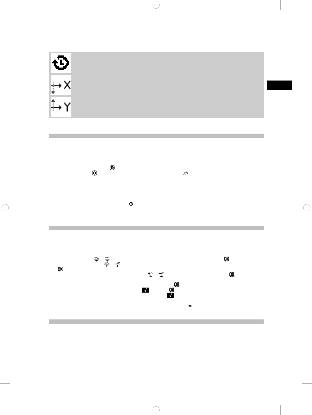
Last previously used inclination value
X-axis
Y-axis
The inclination can be set manually, automatically, or by using the PRA 79 slope adapter.
6.8.1 Setting up
1. Mount the rotating laser on a tripod.
2. Position the rotating laser at the first reference point either at the upper edge or lower edge of the inclined plane.
3. Position yourself behind the tool, facing the control panel.
4. With the aid of the visual sighting method (using the front and rear sights on the head of the tool), aim the tool
roughly at the second reference point, keeping it parallel to the inclined plane.
5. Switch the laser receiver on .
6. Switch the tool on and then press the “Inclined plane mode” key .
The “Inclined plane mode” LED then lights.
The laser beam switches on as soon as the tool has leveled itself. The control panel of the PRA 300 then offers
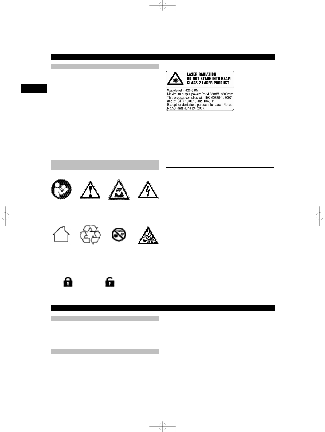
the following ways of adjusting the inclination:
– Digital adjustment of the X or Y values .
– Switch off the leveling control (to allow use with the PRA 79 slope adapter)
– Recall the last previously used value .
For more precise adjustment, first set the inclination and then carry out manual electronic inclination alignment
(see 6.8.2.1). Inclination can be set and displayed on the PRA 300 in %, ⁰⁄₀₀ or in ° (see 6.5.4).
6.8.2 Setting the inclination manually (digital entry)
Inclination values of up to 20% can be entered with the laser receiver / remote control unit. The display on the laser
receiver shows the angle of inclination. If a slope adapter or an already inclined tripod is also used, inclinations of up
to 25% can be achieved.
You can set the X and Y inclinations at the same time or for just one of the two axes.
1. Use the arrow keys or to select soft key X and then confirm your choice by pressing .
2. Then use the arrow keys or to select the digit or character that you wish to set and activate it by pressing
.
3. Enter the desired value by way of the arrow keys or and confirm each digit by pressing – only then can
a new digit be selected.
4. After entering the desired value, confirm your input by pressing .
5. Use the arrow keys to navigate to the OK key and press .
6. You can now enter the Y-value or go straight to “Confirm” . The laser beam will be adjusted only when you
confirm this step.
NOTE Alternatively, before confirming, you can press the “Back” key and return to the main menu, thereby
deleting the entries you have made.
6.8.2.1 Optional manual electronic inclination alignment
After aligning the rotating laser approximately and setting the inclination as described above, alignment of the
PR 300-HV2S can be optimized through use of Hilti’s patented manual electronic alignment system.
1. Position the PRA 300 centrally opposite the PR 300-HV2S at the end of the inclined plane. It can be held still by
hand or fixed in place with the aid of the PRA 83.
NOTE The detection area must be aligned with the second reference point.
en
17

2. Activate manual electronic inclination alignment on the PR 300-HV2S by pressing the “Electronic inclination
alignment” key.
If the arrows for electronic inclination alignment blink, the PRA 300 is receiving no laser beam from the
PR 300-HV2S.
3. If the left arrow lights, turn the PR 300-HV2S clockwise.
4. If the right arrow lights, turn the PR 300-HV2S counter-clockwise.
When both arrows light, the PRA 300 is correctly aligned.
After successful alignment (both arrows light constantly for 10 seconds), the function ends automatically.
5. Then secure the rotating laser on the tripod so that it cannot be inadvertently moved out of position.
6. You can also end electronic inclination alignment by pressing the “End manual electronic inclination alignment”
key.
NOTE There may be divergence between the results obtained by approximate alignment with the aid of the
visual sighting method (using the front and rear sights) and fine alignment with the aid of manual electronic
inclination alignment. As the manual electronic method is more accurate than the visual method, we recommend
that electronic inclination alignment is always used as the reference.
6.8.3 Measuring a given inclination automatically
With this function you can create an inclined laser plane between 2 points automatically and determine the angle of
inclination between these points.
1. Set up the rotating laser at the top edge of the inclined plane as described in 6.8.1.
2. Mount the laser receiver with the PRA 83 receiver holder, for example, on the PUA 53 telescopic staff.
3. Position the receiver immediately in front of the rotating laser, bring it into alignment with the laser plane at the
correct height, and then secure it at the second reference point on the telescopic staff.
4. Position the receiver on the telescopic staff at the lower edge of the inclined plane, click the “Automatic alignment”
key and confirm this by pressing .
NOTE Double-click the AUTO key again to complete the alignment procedure.
The laser plane alignment procedure then begins. A constant signal tone is emitted while this is taking place.
5. The direction of the search can be changed by pressing the “Automatic alignment” key once.
As soon as the laser beam strikes the detection area of the laser receiver, the beam is fixed at the position of the
marking notch (reference plane). Once the position is reached (i.e. the marking notch is found), a signal tone with
a duration of five seconds indicates that the process is complete.
The “Automatic alignment” symbol is no longer shown in the display on the laser receiver and the receiver
switches automatically to normal operating mode.
The new inclination is shown in the display on the laser receiver.
6. Read the inclination between the two points (positions of the rotating laser and the laser receiver) from the display
of the laser receiver.
6.8.4 Setting the inclination with the aid of the PRA 79 slope adapter
NOTE
Check that the slope adapter is fitted correctly between the tripod and the tool (please refer to the operating instructions
for the PRA 79).
1. Set up the PRA 79 slope adapter in a suitable position for the application, e.g. on a tripod.
2. Position the tripod either at the upper edge or lower edge of the inclined plane.
3. Mount the rotating laser on the slope adapter and, with the aid of the sights on the head of the PR 300-HV2S,
adjust the tool and slope adapter so that they are parallel to the inclined plane. The control panel of the
PR 300-HV2S should face away from the direction of inclination.
4. Make sure that the slope adapter is in the zero position (0°).
5. Switch the tool on (see 6.3).
6. Press the “Inclined plane mode” key .
The “Inclined plane mode” LED then lights on the control panel of the rotating laser.
The tool then begins automatic self-leveling. The laser switches on and begins to rotate as soon as this is
complete.
7. On the receiver, now press to deactivate the leveling function.
8. Set the slope adapter to the desired angle of inclination.
NOTE When the angle of inclination is set manually, the PR 300-HV2S levels the laser plane once and then
subsequently fixes it. Vibration, changes in temperature or other influences that may occur during the course of
the day may affect the position of the laser plane.
NOTE In order to enter digital manual settings for X/Y, you must first set the tool to the standard operating mode.
To do this, the system must be restarted.
en
18

6.9 Recalling the last previous value
If you switch the tool off to reposition it, the last previous inclination value saved in the receiver can be recalled.
1. Switch the tool on again and activate inclined plane mode .
The first item in the menu is the last previous value.
2. Press to select the value.
3. Check that the X and Y-values are, in fact, correct.
4. Confirm the values by pressing .
The rotating laser then resets itself to the previous inclination.
6.10 Resetting the X/Y value
Use the “Reset to 0” soft key to quickly reset the X and Y-values to 0.
6.11 Returning to standard mode
To return to standard operating mode, switch the tool off and then switch it back on again.
7 Care and maintenance
7.1 Cleaning and drying
1. Blow dust off exit windows.
2. Do not touch the glass with the fingers.
3. Use only a clean, soft cloth for cleaning. If necessary,
moisten the cloth slightly with pure alcohol or a little
water.
NOTE Abrasive cleaning materials may scratch the
glass and impair the accuracy of the laser tool.
NOTE Do not use any other liquids as these may
damage the plastic components.
4. Dry the equipment, observing the maximum tem-
peratures given in the technical data.
NOTE Especially in summer and winter, take care
that the given maximum and minimum temperatures
are not exceeded, e.g. when the equipment is stored
in a motor vehicle.
7.2 Care of Li‑ion batteries
NOTE
With Li-ion batteries, a conditioning charge (as is required
with NiCd or NiMH batteries) is not necessary.
NOTE
Interruption of the charging procedure has no negative
effect on battery life.
NOTE
Charging can be started at any time with no negative ef-
fect on battery life. There is no memory effect (in contrast
to NiCd or NiMH batteries).
NOTE
For best results, batteries should be stored fully charged
in a cool, dry place. Storing the battery in places subject
to high ambient temperatures (e.g. at a window) has an
adverse effect on battery life and increases the rate of
self-discharge.
NOTE
Batteries lose capacity due to aging and overstressing.
They can then no longer be fully charged. You may
continue to work with a battery that shows signs of
aging, but the battery should be replaced in good time.
1. Avoid ingress of moisture.
2. Charge the battery fully before using it for the first
time.
3. Charge the battery as soon as performance drops
noticeably.
NOTE Recharging in good time will increase the
service life of the battery.
NOTE If use of the battery continues, further dis-
charge will be stopped automatically before the
battery cells suffer damage, i.e. the tool switches
itself off.
4. Charge the batteries using only the Hilti chargers
approved for use with Li-ion batteries.
7.3 Storage
1. Remove the tool from its case if it has become wet.
Dry and clean the tool, its transport container and
accessories (while observing the permissible tem-
perature range). Repack the equipment only once it
is completely dry.
2. Check the accuracy of the equipment before it is
used after a long period of storage or transportation.
3. Remove rechargeable and non-rechargeable batter-
ies from the tool or the laser receiver before storing
the units for long periods. The tool or laser re-
ceiver may suffer damage caused by leakage from
rechargeable or non-rechargeable batteries.
7.4 Transport
Use the Hilti toolbox or packaging of equivalent quality
for transporting or shipping your equipment.
CAUTION
Always remove the batteries before shipping the tool.
7.5 Hilti Measuring Systems Service
Hilti Measuring Systems Service checks the tool and, if
deviations from the specified accuracy are found, recal-
en
19

ibrates the tool and checks it again to ensure conformity
with specifications. The service certificate provides writ-
ten confirmation of conformity with specifications at the
time of the test.
The following is recommended:
1. The tool should be checked at suitable intervals,
depending on the frequency of normal use.
2. The tool should be checked at least once a year by
a Hilti Measuring Systems Service Center.
3. The tool should be checked by a Hilti Measuring
Systems Service Center if it has been abused in any
way.
4. The tool should be checked by a Hilti Measuring
Systems Service Center before being used for par-
ticularly important work.
Having the tool checked by a Hilti Measuring Sys-
tems Service Center does not relieve the user of
his/her obligation to check the tool before and dur-
ing use.
7.6 Checking accuracy
NOTE
In order to ensure compliance with the technical spe-
cifications, the tool should be checked regularly (at least
before each major / relevant job).
NOTE
After falling and suffering an impact it can be assumed
that the tool will continue to operate faultlessly, with
the accuracy it achieved prior to the impact, when the
following conditions are met:
The height of the fall did not exceed the height given in
the technical data.
The tool suffered no obvious mechanical damage from
the impact (e.g. breakage of the pentaprism).
The tool projects a rotating laser beam when in operation.
The tool operated faultlessly before the impact.
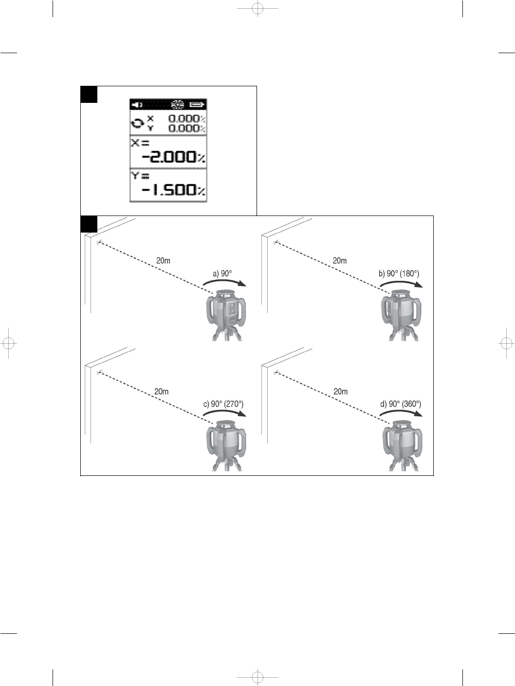
7.6.1 Checking the main and transverse horizontal
axes
1. Set up the tripod approx. 20 m (66 ft) from a wall
and adjust the tripod head horizontally with a spirit
level.
2. Mount the tool on the tripod and use the visual
sighting method (front and rear sights) to aim the
tool at the wall.
3. Use the receiver to catch the laser beam and mark
a point (point 1) on the wall.
4. Pivot the tool clockwise through 90° about its own
axis. In doing so, ensure that the height of the tool
does not change.
5. Use the laser receiver to catch the laser beam and
mark a second point (point 2) on the wall.
6. Repeat steps 4 and 5 twice and mark points 3 and
4 on the wall with the aid of the laser receiver.
When this is done carefully, the vertical distance
between the two marked points, i.e. points 1 and 3
(main axis) or points 2 and 4 (transverse axis) should
be < 2 mm (0.08 in) at 20 m (66 ft) in each case. If
the deviation is greater than this, the tool should be
returned to a Hilti Service Center for calibration.
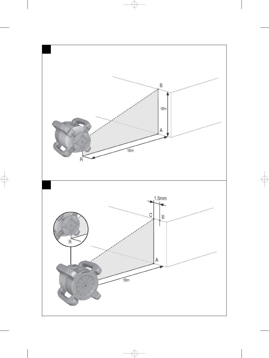
7.6.2 Checking the vertical axis
1. Place the tool in the vertical position on a floor,
which is as flat as possible, approx. 10 m (33 ft)
from a wall.
2. Adjust the position of the tool so that the grips are
parallel to the wall.
3. Switch the tool on and mark the reference point (R)
on the floor.
4. With the aid of the receiver, mark point (A) low on
the wall.
5. With the aid of the receiver, mark point (B) at a
height of approx. 10 m (33 ft).
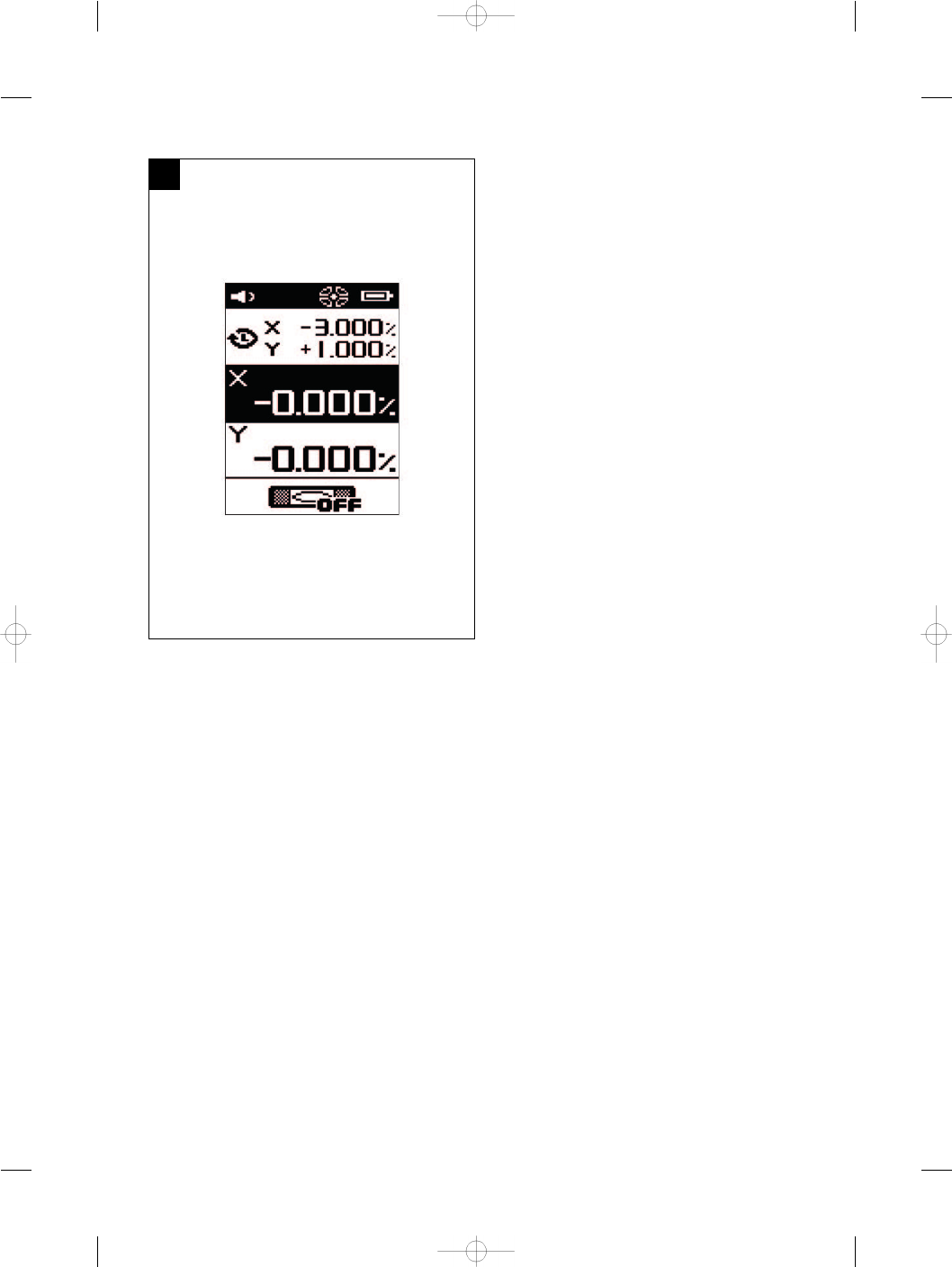
6. Pivot the tool through 180° and realign it with the
reference point (R) on the floor and with point (A) at
the base of the wall.
7. With the aid of the receiver, mark point (C) at a
height of approx. 10 m (33 ft).
8. Check the distance between points (B) and (C).
When the procedure has been carried out carefully,
the horizontal distance between the two points (B)
and (C) marked at a height of ten meters should be
less than 1 mm (0.04 in) at 10 m (33 ft).
NOTE If the deviation is greater: Please return the
tool to Hilti Service for calibration.
8 Troubleshooting
Every item shown in the display is accompanied by either the “Information” or the “Warning” symbol (see section
“Overview of general symbols”).
Message displayed Fault Possible cause Remedy
Inclination angle too high.
The tool cannot achieve
the given inclination.
Inclination angle too high Reposition the tool so
that the inclination value
you have entered can be
achieved.
en
20
Message displayed Fault Possible cause Remedy
Rotating laser in wrong
position.
The tool cannot level it-
self.
The tool is not correctly
positioned – is already too
steeply inclined.
The tool must be reposi-
tioned in order to bring it
within the leveling range.
Rotating laser shock
The tool has been subjec-
ted to shock.
The rotating laser has
been subjected to shock
– accuracy can no longer
be guaranteed.
Restart the system and
take a reference measure-
ment before continuing
your work.
Surveillance interrupted
Surveillance between the
tool and the laser receiver
has been interrupted.
The receiver has received
no laser beam for more
than 2 minutes.
The tool must be restar-
ted and alignment of the
vertical laser beam then
carried out again.
Receiver battery symbol
The receiver’s battery is
almost empty.
The receiver’s battery is
almost empty.
Charge the battery soon.
Rotating laser battery
symbol
The rotating laser’s bat-
tery is almost empty.
The rotating laser’s bat-
tery is almost empty.
Charge the battery soon.
Tripod battery symbol
The tripod’s battery is al-
most empty.
The tripod’s battery is al-
most empty.
Charge the battery soon.
Autoalignment
The Autoalignment pro-
cess was canceled.
The receiver could find
no laser beam within 2
minutes.
The process must be re-
started.
Autoalignment not pos-
sible
Autoalignment is not pos-
sible at the moment.
Autoalignment is not pos-
sible while certain menu
items are being executed.
Close the current menu
and try again.
Receiver battery symbol
The receiver’s battery is
empty.
The receiver’s battery is
empty.
Charge the battery.
Rotating laser battery
symbol
The rotating laser’s bat-
tery is empty.
The rotating laser’s bat-
tery is empty.
Charge the battery.
Tripod battery symbol
The tripod battery is
empty.
The tripod’s battery is
empty.
Charge the battery.
en
21
9 Disposal
WARNING
Improper disposal of the equipment may have serious consequences:
The burning of plastic components generates toxic fumes which may present a health hazard.
Batteries may explode if damaged or exposed to very high temperatures, causing poisoning, burns, acid burns or
environmental pollution.
Careless disposal may permit unauthorized and improper use of the equipment. This may result in serious personal
injury, injury to third parties and pollution of the environment.
Most of the materials from which Hilti tools or appliances are manufactured can be recycled. The materials must
be correctly separated before they can be recycled. In many countries, Hilti has already made arrangements for
taking back old tools and appliances for recycling. Ask Hilti customer service or your Hilti representative for further
information.
Dispose of the batteries in accordance with national regulations.
10 Manufacturer’s warranty - tools
Please contact your local Hilti representative if you have
questions about the warranty conditions.
11 FCC statement (applicable in US) / IC statement (applicable in Canada)
CAUTION
This equipment has been tested and found to comply
with the limits for a class B digital device, pursuant to
part 15 of the FCC rules. These limits are designed to
provide reasonable protection against harmful interfer-
ence in a residential installation. This equipment gen-
erates, uses and may radiate radio frequency energy.
Accordingly, if not installed and used in accordance with
the instructions, it may cause harmful interference to
radio communications.
However, there is no guarantee that interference will not
occur in a particular installation. If this equipment does
cause harmful interference to radio or television recep-
tion, which can be determined by turning the equipment
off and on, the user is encouraged to try to correct the
interference by taking the following measures:
Reorient or relocate the receiving antenna.
Increase the separation between the equipment and re-
ceiver.
Connect the equipment to a power outlet on a circuit
different from that to which the receiver is connected.
Consult your dealer or an experienced TV/radio techni-
cian for assistance.
NOTE
Changes or modifications not expressly approved by
Hilti may restrict the user’s authorization to operate the
equipment.
This device complies with part 15 of the FCC Rules and
RSS-210 of the IC.
Operation is subject to the following two conditions:
This device should cause no cause harmful interference.
This device must accept any interference received, in-
cluding interference that may cause undesired operation.
en
22