Hilti PRA2XR01 Laserdetector User Manual DRAFT
Hilti Corporation Laserdetector DRAFT
UserManual.wiki
>
Hilti
>
PRA2XR01 User Manual
User Manual
Navigation menu
Upload a User Manual
Namespaces
Wiki Guide
HTML
PDF
Info
Views
User Manual
Discussion / Help
Navigation
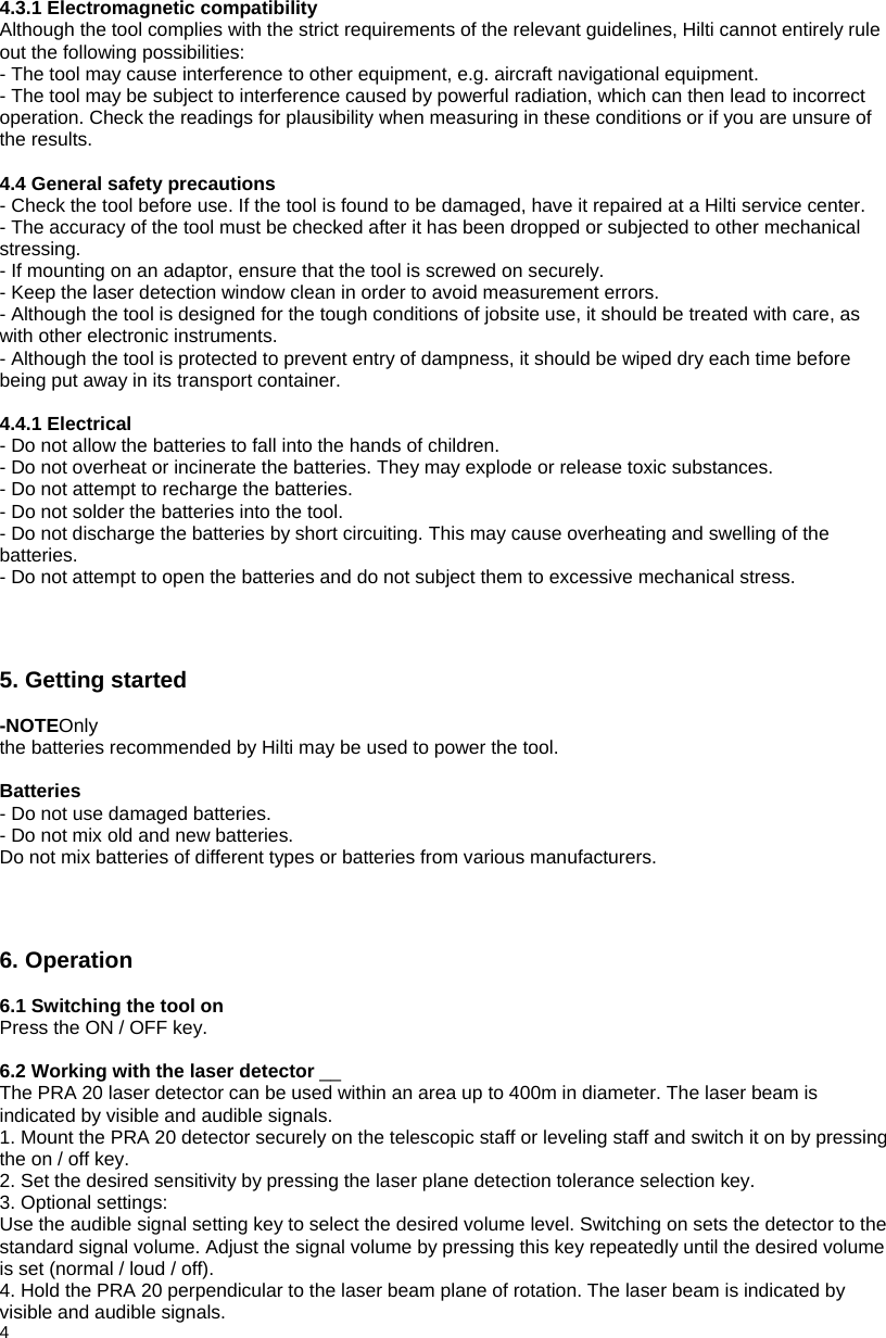
![On both sides Automatic cut-out The detector switches itself off after 30 min. when no laser beam is detected. Dimensions 165x67x24mm (6.5"x2.6"x0.9" inches) Weight 0.2 kg (0.4 lbs) including batteries Power supply 2 x size AA batteries Battery life at 20°C [+68°] Alkaline batteries: > approx. 30 hours Operating temperature -20° to +50°C (-4° to +122°F) Storage temperature -30° to +60°C (-22° to +140°F) Protection class IP 56 (as per IEC 529) Mounting thread on detector M5 x 10 mm (0.4 inch) 4. Safety precautions 4.1 Basic information concerning safety In addition to the information relevant to safety given in each of the sections of these operating instructions, the following points must be strictly observed at all times. 3 4. Safety precautions / 5. Getting started 4.2 Misuse - Modification of the tool is not permissible. - (Requested by FCC §15.21): Changes or modifications not expressly approved by the party responsible for compliance could void the user’s authority to operate the equipment. - Observe the information printed in the operating instructions concerning operation, care and maintenance. - Have the tool repaired only at a Hilti service centre. Failure to follow the correct procedures when opening the tool may cause emission of laser radiation in excess of class 2. - Take the surrounding conditions into account. Do not use the tool where there is a risk of fire or explosion. 4.3 Proper organization of the workplace - Avoid unfavorable body positions when working on ladders. Make sure you have a stable stance and stay in balance at all times. - Measurements taken through panes of glass or other objects may be inaccurate. - Use the tool only within its specified limits. Gelöscht: 50](https://usermanual.wiki/Hilti/PRA2XR01/User-Guide-462134-Page-3.png)