Hilti PRA3XR01 Rotating Laser User Manual Hilti Omega
Hilti Corporation Rotating Laser Hilti Omega
Hilti >
Users Manual

Hilti Corporation
FL‑9494 Schaan
Tel: +423 / 234 21 11
Fax: +423 / 234 29 65
www.hilti.com
N
D
1
23

ORIGINAL OPERATING INSTRUCTIONS
PRA 35 remote control / laser receiver
It is essential that the operating instructions
are read before the tool is operated for the
first time.
Always keep these operating instructions
together with the tool.
Ensure that the operating instructions are
with the tool when it is given to other
persons.
Contents Page
1. General information 1
2. Description 2
3. Technical data 3
4. Safety instructions 4
5. Before use 5
6. Operation 5
7. Care and maintenance 6
8. Disposal 6
9. Manufacturer’s warranty - tools 7
10. FCC statement (applicable in USA) 7
11. EC declaration of conformity 8
1These numbers refer to the corresponding illustra-
tions. The illustrations can be found on the fold-out
cover pages. Keep these pages open while studying
the operating instructions.
In these operating instructions, the designation “the
tool” always refers to the PRA 35 laser receiver.
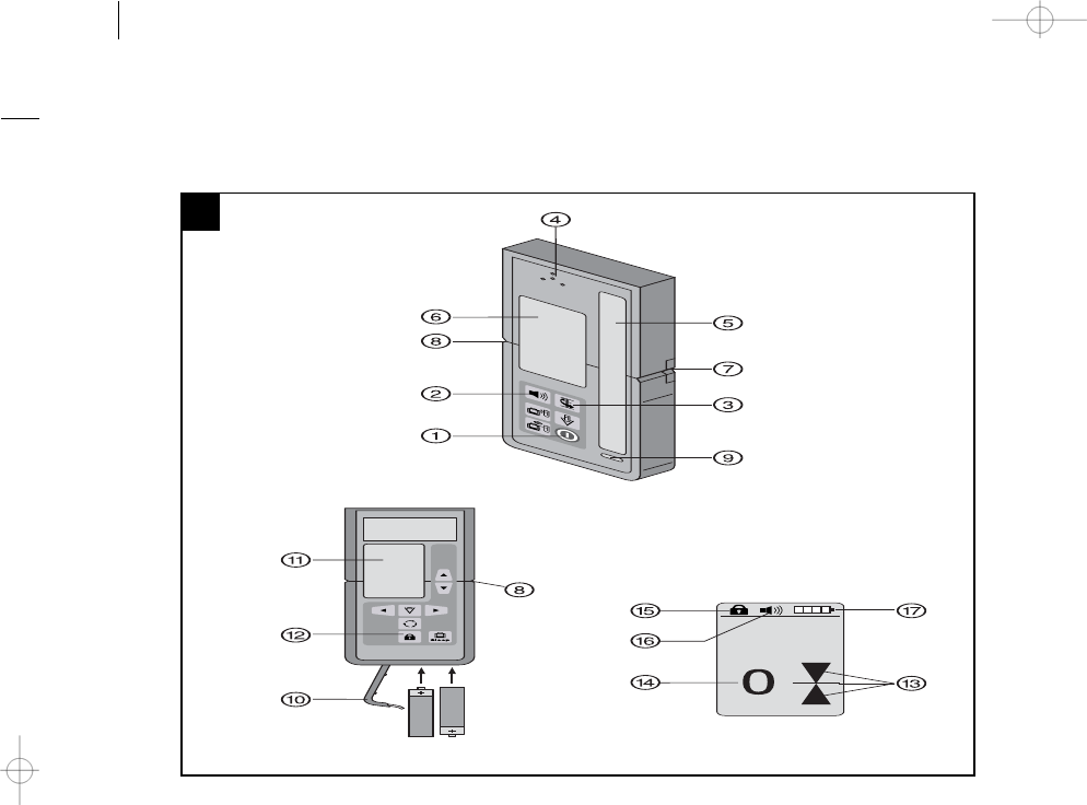
Parts, operating controls and indicators 1
PRA 35 remote control / laser receiver
@On/off button
;Signal tone button
=Units button
%Signal tone aperture
&Receiving area
(Display area, front
)Marking notch
+Reference plane
§Bubble level
/Battery compartment cover
:Display area, rear
·Button lock
PRA 35 laser receiver display
$Display showing the position of the receiver
relative to the height of the laser plane
£Exact distance of the receiver from the laser
plane
|Button lock
¡Volume
QBattery status indicator
1. General information
1.1 Safety notices and their meaning
DANGER
Draws attention to imminent danger that could lead
to serious bodily injury or fatality.
WARNING
Draws attention to a potentially dangerous situation
that could lead to serious personal injury or fatality.
CAUTION
Draws attention to a potentially dangerous situation
that could lead to slight personal injury or damage to
the equipment or other property.
NOTE
Draws attention to an instruction or other useful
information.
en
1
1.2 Explanation of the pictograms and other
information
Warning signs
General
warning
Symbols
Read the
operating
instructions
before use
Return waste
material for
recycling.
Location of identification data on the tool
The type designation and serial number can be found
on the type identification plate on the tool. Make a
note of this data in your operating instructions and
always refer to it when making an enquiry to your
Hilti representative or service department.
Type:
Generation: 01
Serial no.:
2. Description
2.1 Use of the product as directed
The Hilti PRA 35 can be used to remotely control the PR 35 rotating laser and to detect and locate the laser
beam. These operating instructions apply only to operation of the PRA 35 laser receiver. For information about
the remote control functions, please refer to the operating instructions for the PR 35.
In conjunction with the PR 35, the tool can be used to determine, transfer and check horizontal levels and
heights, verticals, inclined planes and right angles, e.g. transferring datums and height marks, determining or
checking right angles for walls, vertical alignment from a reference point and setting out slopes.
Observe the information printed in the operating instructions concerning operation, care and maintenance.
Take the influences of the surrounding area into account. Do not use the tool where there is a risk of fire or
explosion.
Modification of the tool or tampering with its parts is not permissible.
2.2 Features
The tool can be held by hand or mounted on a leveling staff, timber batten or frame etc., using the applicable
holder.
2.3 Indicators
NOTE
The display of the PRA 35 laser receiver uses several symbols to indicate various modes or statuses.
Indication of the position of the receiver relative
to the laser plane
The position of the receiver relative to the laser plane is
shown by an arrow indicating the direction in which the
receiver has to be moved in order to bring it exactly into
alignment with the laser.
Battery status indicator The battery status indicator shows the remaining battery
capacity.
en
2

Volume level When no volume level symbol is visible in the display, the
volume level is set to zero (off). If 1 column is shown,
the volume is set to “quiet”. If 2 columns are shown, the
volume is set to “normal”. If 3 columns are shown, the
volume is set to “loud”.
Offset indicator Shows the exact distance of the receiver from the laser
plane in the desired measuring units.
Other indicators Other indicators in the display refer to the PR 35 rotating
laser when controlled remotely. For further information,
please refer to the PR 35 operating instructions.
2.4 Items supplied
1 PRA 35 remote control / laser receiver
1 PRA 35 operating instructions
2 Batteries
1 Manufacturer’s certificate
3. Technical data
Right of technical changes reserved.
Detection range (area diameter) 2…300 m (6 to 1000 ft)
Signal tone generator 3 volume levels plus mute setting
Liquid crystal display On both sides
Indicator range, distance from zero ±50mm(±2in)
Laser plane indication area ± 0.5 mm (± 0.02 in)
Width of receiving area 120 mm (5 in)
Center indication from top edge of casing 75 mm (3 in)
Marking notches On both sides
Automatic power-off When no beam is detected: 15 min
Dimensions 160 mm X 67 mm X 24 mm
Weight (including batteries) 0.25 kg (0.6 lbs)
Power source 2 AA‑size batteries
Battery life (alkaline-manganese) Temperature +20°C (+68 °F): 40 h
Operating temperature range -20…+50°C (-4°F to 122°F)
Storage temperature -25…+60°C (-13 °F to 140 °F)
Protection class IP 56
in accordance with IEC 529
en
3
4. Safety instructions
4.1 Basic information concerning safety
In addition to the information relevant to safety
given in each of the sections of these operating
instructions, the following points must be strictly
observed at all times.
4.2 General safety rules
a) Keep other persons, especially children, away
from the area in which the work is being carried
out.
b) Check the condition of the tool before use. If the
tool is found to be damaged, have it repaired at
a Hilti service center.
c) Have the tool repaired only at a Hilti service
center.
d) Do not render safety devices ineffective and do
not remove information and warning notices.
e) The tool must be checked at a Hilti service
center after it has been dropped or subjected to
other mechanical stresses.
f) If mounting on an adapter, check that the tool
is fitted correctly.
g) To avoid measurement errors, the receiving
area must be kept clean.
h) Although the tool is designed for the tough con-
ditions of jobsite use, as with other optical and
electronic instruments (e.g. binoculars, spec-
tacles, cameras) it should be treated with care.
i) Although the tool is protected to prevent entry
of dampness, it should be wiped dry each time
before being put away in its transport container.
j) To avoid hearing damage, hold the tool as
far away as possible from your ear (and other
persons’ ears).
4.2.1 Electrical
a) Keep the batteries out of reach of children.
b) Do not allow the batteries to overheat and do not
expose them to fire. The batteries may explode
or release toxic substances.
c) Do not charge the batteries.
d) Do not solder the batteries into the tool.
e) Do not discharge the batteries by short circuiting
as this may cause them to overheat and present
a risk of personal injury (burns).
f) Do not attempt to open the batteries and do not
subject them to excessive mechanical stress.
4.3 Proper organization of the work area
a) Avoid unfavorable body positions when working
on ladders or scaffolding. Make sure you work
from a safe stance and stay in balance at all
times.
b) Use the tool only within its specified limits.
c) Measurements taken through or from panes of
glass or through other objects may be inaccurate.
d) Use of the telescopic staff in the vicinity of over-
head high voltage cables is not permissible.
e) Reflection of the laser beam from glass or other
reflective surfaces may cause errors or incorrect
results.
4.4 Electromagnetic compatibility
Although the tool complies with the strict require-
ments of the applicable directives, Hilti cannot en-
tirely rule out the possibility of the tool being subject
to interference caused by powerful electromagnetic
radiation, leading to incorrect operation. Check the
accuracy of the tool by taking measurements by other
means when working under such conditions or if you
are unsure. Likewise, Hilti cannot rule out the pos-
sibility of interference with other devices (e.g. aircraft
navigation equipment).
en
4
5. Before use
5.1 Inserting the batteries 1
CAUTION
Do not use damaged batteries.
DANGER
Do not mix old and new batteries. Do not mix
batteries of different makes or types.
NOTE
Only batteries recommended by Hilti may be used to
power the tool.
6. Operation
6.1 Switching the tool off and on 1
Press the “On/off” button.
Check to ensure that the button lock on the receiver
side is deactivated. Deactivation is indicated by the
open lock symbol in the display.
Please note that all remote control buttons on the
PRA 35 function only in conjunction with a PR 35
rotating laser. For information about the button func-
tions, please refer to the PR 35 operating instructions.
6.2 Working with the tool
The PRA 35 laser receiver can be used at distances
(radiuses) of up to 150m (500ft). The laser beam is
indicated visually and by a signal tone.
6.2.1 Using the laser receiver as a hand-held
tool
1. Press the “On/off” button.
2. Hold the PRA 35 in the plane of the rotating laser
beam.
The laser beam is indicated by visual and audible
signals.
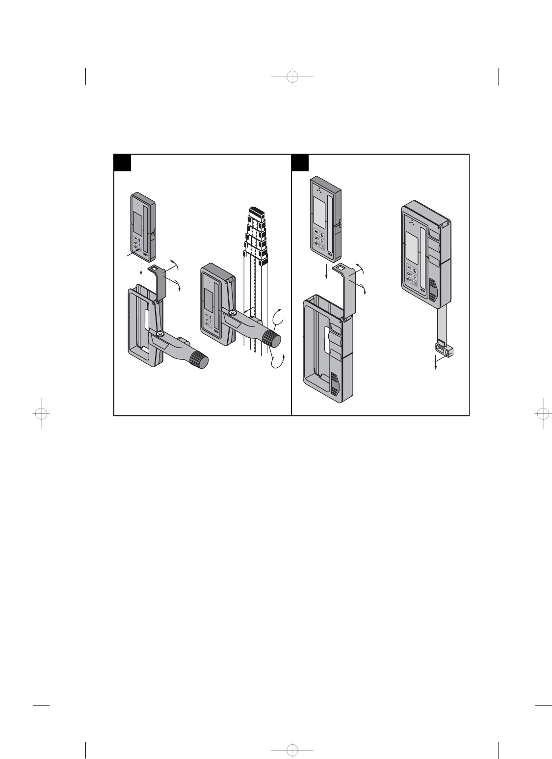
6.2.2 Working with the laser receiver in the
PRA 80 receiver holder 2
1. Open the catch on the PRA 80.
2. Place the PRA 35 in the PRA 80 receiver holder.
3. Close the catch on the PRA 80.
4. Switch the PRA 35 on by pressing the “On/off”
button.
5. Rotate the grip to bring it into the open position.
6. Secure the PRA 80 receiver holder on the tele-
scopic staff or leveling staff by turning the rotat-
ing grip.
7. Hold the PRA 35 with the receiving window
directly in the plane of the rotating laser beam.
The laser beam is indicated by visual and audible
signals.
6.2.3 Working with the PRA 81 3
1. Open the locking mechanism on the PRA 81.
2. Insert the PRA 35 laser receiver in the PRA 81
height transfer device.
3. Close the locking mechanism on the PRA 81.
4. Switch the PRA 35 on by pressing the “On/off”
button.
5. Position the PRA 35 so that the distance display
shows “0”.
6. Hold the PRA 35 with the receiving window
directly in the plane of the rotating laser beam.
7. Use the measuring tape to measure the desired
offset distance.
6.2.4 Menu options
When switching the PRA 35 on, press and hold the
“On/off” button for two seconds.
The menu is then shown in the display.
Use the “Units” button to switch between metric and
imperial units.
Use the “Volume” button to assign the more rapid
signal tone to the upper or lower area of the receiving
window.
To save the settings, switch the PRA 35 off.
en
5

6.2.5 Setting the measuring unit
The “Units” button can be used to set the desired
measuring unit according to the country of use (mm
/ cm / off) or (¹⁄₈in / ¹⁄₁₆in / off).
6.2.6 Setting the volume of the signal tone
The tool is set to “Normal” volume when switched on.
The volume can be adjusted by pressing the “Signal
tone” button. One of the following settings can be
selected: “Low”, “Normal”, “High” or “Off”.
7. Care and maintenance
7.1 Cleaning and drying
1. Blow dust off the surfaces.
2. Do not touch the display areas or the receiving
window with the fingers.
3. Use only a clean, soft cloth for cleaning. If
necessary, moisten the cloth slightly with pure
alcohol or a little water.
NOTE Do not use any other liquids as these may
damage the plastic components.
4. Observe the temperature limits when storing
your equipment. This is particularly important in
winter / summer if the equipment is kept inside a
motor vehicle (25°C to +60°C / -13°F to +140°F).
7.2 Storage
Remove the tool from its case if it has become wet.
The tool, its carrying case and accessories should be
cleaned and dried (at maximum 40°C / 104°F). Repack
the equipment only once it has dried completely and
then store it in a dry place.
Check the accuracy of the equipment before it is used
after a long period of storage or transportation.
Remove the batteries from the tool before storing it
for a long period. Leaking batteries may damage the
tool.
7.3 Transport
Use the Hilti toolbox or packaging of equivalent quality
for transporting or shipping your equipment.
DANGER
Always remove the batteries before transporting the
tool.
7.4 Hilti calibration service
We recommend that the tool is checked by the Hilti
calibration service at regular intervals in order to
verify its reliability in accordance with standards and
legal requirements.
Use can be made of the Hilti calibration service
at any time, but checking at least once a year is
recommended.
The calibration service provides confirmation that the
tool is in conformance, on the day it is checked, with
the specifications given in the operating instructions.
The tool will be readjusted if deviations from the
manufacturer’s specification are found. After check-
ing and adjustment, a calibration sticker applied to
the tool and a calibration certificate provide written
verification that the tool operates in accordance with
the manufacturer’s specification.
Calibration certificates are always required by com-
panies certified according to ISO 900x.
Your local Hilti Center or representative will be pleased
to provide further information.
8. Disposal
DANGER
Improper disposal of the equipment may have serious consequences:
The burning of plastic components generates toxic fumes which may present a health hazard.
Batteries may explode if damaged or exposed to very high temperatures, causing poisoning, burns, acid burns
or environmental pollution.
Careless disposal may permit unauthorized and improper use of the equipment. This may result in serious
personal injury, injury to third parties and pollution of the environment.
en
6
Most of the materials from which Hilti tools or appliances are manufactured can be recycled. The materials must
be correctly separated before they can be recycled. In many countries, Hilti has already made arrangements
for taking back old tools and appliances for recycling. Ask Hilti customer service or your Hilti representative
for further information.
For EC countries only
Disposal of electric appliances together with household waste is not permissible.
In observance of European Directive 2002/96/EC on waste electrical and electronic equipment
and its implementation in accordance with national law, electric tools that have reached the end
of their life must be collected separately and returned to an environmentally compatible recycling
facility.
Dispose of the batteries in accordance with national regulations.
9. Manufacturer’s warranty - tools
Hilti warrants that the tool supplied is free of defects
in material and workmanship. This warranty is valid
so long as the tool is operated and handled correctly,
cleaned and serviced properly and in accordance with
the Hilti Operating Instructions, and the technical
system is maintained. This means that only original
Hilti consumables, components and spare parts may
be used in the tool.
This warranty provides the free-of-charge repair or
replacement of defective parts only over the entire
lifespan of the tool. Parts requiring repair or replace-
ment as a result of normal wear and tear are not
covered by this warranty.
Additional claims are excluded, unless stringent na-
tional rules prohibit such exclusion. In particular,
Hilti is not obligated for direct, indirect, incidental
or consequential damages, losses or expenses in
connection with, or by reason of, the use of, or
inability to use the tool for any purpose. Implied
warranties of merchantability or fitness for a par-
ticular purpose are specifically excluded.
For repair or replacement, send the tool or related
parts immediately upon discovery of the defect to
the address of the local Hilti marketing organization
provided.
This constitutes Hilti’s entire obligation with regard
to warranty and supersedes all prior or contempor-
aneous comments and oral or written agreements
concerning warranties.
10. FCC statement (applicable in USA)
CAUTION
This equipment has been tested and found to comply
with the limits for a class B digital device, pursuant
to part 15 of the FCC rules. These limits are designed
to provide reasonable protection against harmful in-
terference in a residential installation. This equipment
generates, uses, and can radiate radiofrequency en-
ergy and, if not installed and used in accordance with
the instructions, may cause harmful interference to
radio communications.
en
7