Hisense Electric LCDD0030 Part15 Subpart B-LED LCD TV User Manual W9HLCDD0030 2
Hisense Electric Co., Ltd. Part15 Subpart B-LED LCD TV W9HLCDD0030 2
Contents
- 1. W9HLCDD0030_User Manual 1
- 2. W9HLCDD0030_User Manual 2
W9HLCDD0030_User Manual 2
K366 Series
CY-G131605
ctual product.
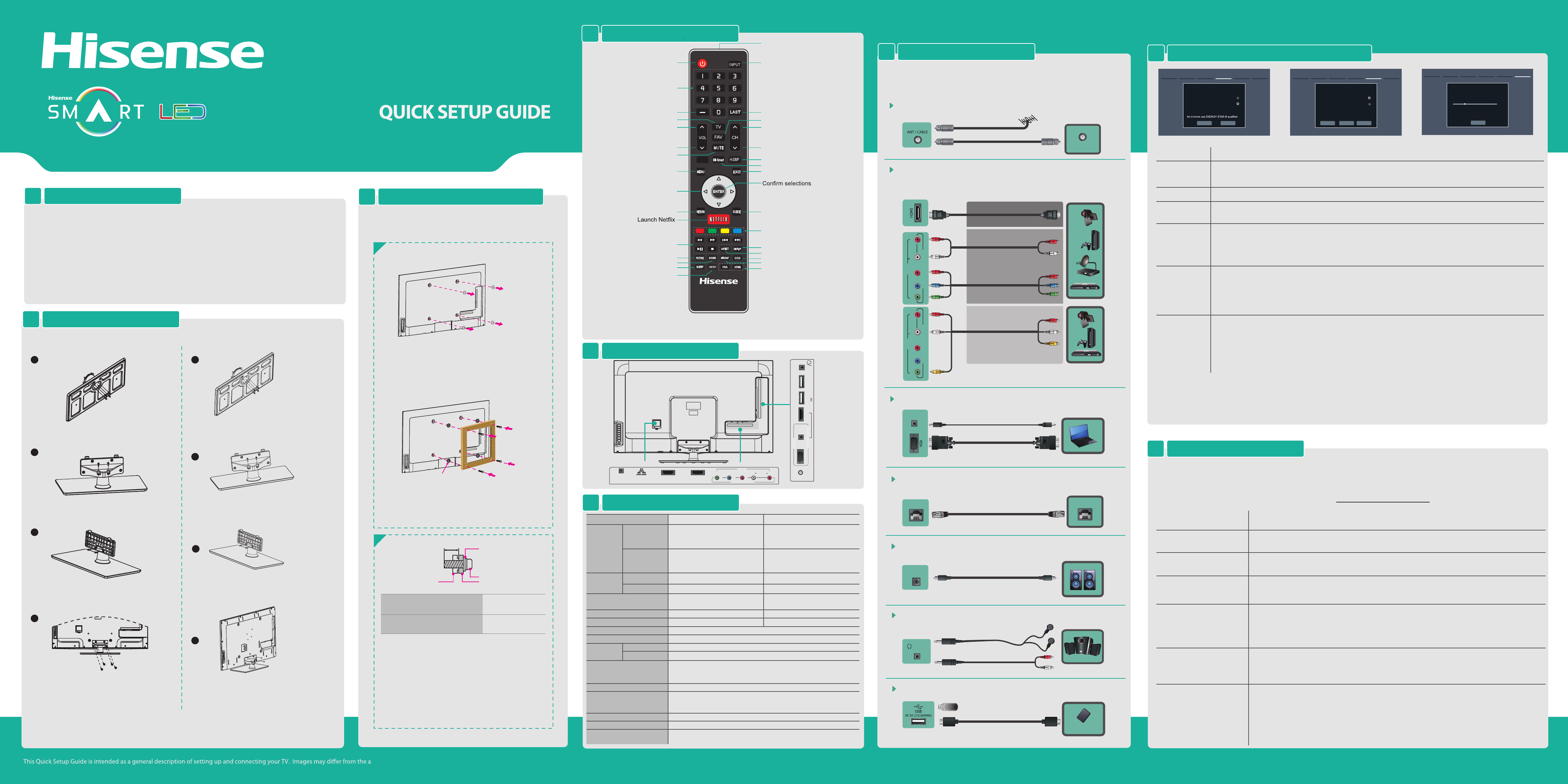
Check the jacks for position and type before making any connections.
Loose connections can result in image or color problems. Make sure that all
connections are tight and secure.
TV CONNECTORS7
Barcode
35*10.5mm
REMOTE CONTROL4
SPECIFICATIONS6
When there is something wrong with your TV, you can try turning o the TV and restarting it. You can also refer to the following
chart for problem and solution tips. If the problem cannot be resolved, please contact Hisense for additional assistance.
Your TV aslo contains material that can be recycled and reused. For disposal or recycling information, contact your local
authorities or the Electronic Products Recycling Association at http://www.eprassociation.ca to nd a recycler in your area.
• Confirm power cord is plugged into the AC outlet and the AC outlet is getting electricity.
• Attempt to power on unit using the power button on both the TV and the Remote.
• Check for the correct output connection on the external source and for the correct input connection on the TV.
• Make sure you have made the correct selection for the input mode for the incoming signal.
• Check the volume settings.
• Check if Mute mode is set "on" .
• Check network physical connection, make sure connection is correct.
• Enter "Menu" , "Network" , "Configuration" , make sure configuration is correct according to your network service
provider.
• Enter "Menu" , "Network" , "Configuration" , "Connection Test" to make sure that network connection test is
successful.
• You need a broadband (high speed) Internet service with a speed of no less than 1.5 Mbps.
• Connect the TV to the internet through your router by an Ethernet Cable or wireless. If connection fails, check
with your internet service provider or router manufacturer to determine if there is a firewall, content filter, or
proxy settings that may block the TV from accessing the internet.
• Before calling for service, check the following information for possible solutions to problems you may
experience. If none of these solutions work, turn off the TV, then turn it on again.
• Caution: Do not try to repair the TV yourself. Refer all servicing to qualified repair personnel.
POSSIBLE SOLUTIONSSYMPTOMS
No sound or picture
Picture is normal, but no sound
Network connection fail.
Connect Netix fail.
I have connected an external
source to my TV and I get no
picture and/or sound.
How do I get easy IPTV to work
on my TV?
HELP TOPICS9
• Check network physical connection, make sure connection is correct.
• Enter "Menu" , "Network" , "Configuration" , make sure configuration is correct according to your network service
provider.
• Enter "Menu", "Network", "Applications", "Netflix", "Deactivation" to reset "Netflix" account.
Turning the TV On for the First Time8
Note:
If you are using a cable or satellite box and you have connected it to the TV using a Coaxial cable, you should select the cable option. Be sure the cable or satellite box is turned
on before starting the channel scan. If you use a cable or satellite box connected to A/V, Component or HDMI, you don't need to scan for channels.
INSTALLING A WALL-MOUNT BRACKET
3
1
Make sure the TV is laid face-down on a clean, safe, and
cushioned space, remove the original screws in the bracket
holes on the TV back.
If you want to attach the TV to a wall-mount bracket
(not provided), you should rst remove the stand if it is
pre-attached (see Step 1).
SPACER x4
Place the provided spacers in the corresponding bracket
holes. Attach purchased bracket (1.5mm to 2.5mm thickness)
on the TV with 4 screws which are in the accessories bag.
Follow instructions provided with the wall-mount bracket.
9.5 ~ 11.5 mm
Wall-Mount Bracket
Screw
SpacerThe TV's rear cover
Wall-Mount hole pattern VESA (mm)
Wall-Mount screw size (mm)
2
Follow instructions provided with the Wall-Mount bracket.
• If you are not sure of your ability to do complete the installa-
tion, contact a professional installer or service technician for
assistance. The manufacturer is not responsible for any
damages or injuries that occur due to mishandling or incorrect
assembly.
• The selected screws are 9.5 ~ 11.5 mm in length when
measured from the attaching surface of the TV's rear cover.
The diameter and length of the screws differ depending on the
Wall-Mount Bracket model.
Note: These 4 screws which got from back cover mount hole could not
be used any more.
ACCESSORIES LIST1
•
User Manual
•
Quick Setup Guide
•
Warranty Card
•
Remote Control
•
Battery x 2
Spacer for 40K366WN
•
Screw (M5 x 12mm) x 4
•
Screw (M4 x 12mm) x 6
•
Screw (ST4 x 14mm) x 2
•
Wall-mounted screw (M6 x 30mm) x 4
Spacer for 46K366WN
•
Screw (M5 x 12mm) x 4
•
Screw (M4 x 12mm) x 6
•
Screw (ST4 x 14mm) x 2
•
Wall-mounted screw (M6 x 45mm) x 4
INSTALLING THE STAND2
Follow the illustrations below to complete the installation steps.
M6 x 30mm(40K366WN)/
M6 x 45mm(46k366WN)
Wall monuted-screws
1
2
Secure the stand column to the base plate with the 4
screws (M4 x 12) provided.
3
Secure the stand cover to the stand column vertically
with the 2 screws (M4 x 12) provided.
4
Secure the stand cover to the stand column horizon-
tally with the 2 screws (ST4 x 14) provided.
Secure the stand to the TV with the 4 screws (M5 x
12) provided.
1
2
3
Note:
Product image is only for reference, actual product may vary in appearance. Carefully place your TV facedown on a soft, cushioned surface to
prevent damage to the TV or scratching to the screen.
Previous Next
4.Use Mode Next: Network Setting
Use Mode
Home mode
Retail mode
Home mode default settings are recommended
• Please press [ENTER] to start the wizard, then press [▲/
▲
] button to select your language: English, Spanish or French,
select [Next] to confirm enter the Welcome screen.
• In the Welcome screen introduced the available input devices and interfaces.
• Please press [▲/
▲
] button to select the country where you will operate the TV.
OPERATIONSMENU
Language setting
Country setting
• Select the local time zone according to your region.
• Daylight Saving: Set the Daylight Saving time for your area.
Time zone setting
• Select your Mode Setting: Home Mode or Retail Mode.
• If you select Retail Mode, a message appears “Are you sure to change to retail mode?” Select “OK” to continue, or select
“No” to change your selection.
• Home Mode is the recommended setting which offers full functionality of the television. If you selected Retail Mode, Energy
Saving is not realized.
Use Mode
• The Select Network : Connect your TV to access the network.
• When the Network Setting menu opens, Hisense Service Terms and Conditions will appear. Press [◄/►] to scroll through
the pages. Please read it carefully. If you want to access the internet, press the [Agree] button to set your TV’s network
connections. Otherwise, press the [Disagree] button to enter the Channel search menu.
• You can setup the network configuration in this menu. For more information,
please refer to the section titled
“Network
Connection” and “Network Setup”
in the user manual.
Select Network
• Press [▲/
▲
] to select your Tuner Mode: Antenna or Cable, press [ENTER] button to confirm.
• Press [
▲
/
▲
] to set the Channel Installation: Scan or Skip Scan, press [ENTER] button to confirm. If you select “Scan”, your
TV automatically starts Channel Installation available in your viewing area; If you select “Skip Scan”, your TV does not scan
for channels; Depending on the reception condition, it may take up to 30 minutes or more to complete memorizing channels.
Please allow the process to complete without interruption.
• After scan, you will enter the complete interface. It will display all informations that you set just now and then you can press
“Go” to exit the wizard.
Channel Search
Video Eect:
Connect an outdoor VHF/UHF antenna.
ANT
Connect Headphone for audio out of the TV.
HEADPHONE
/AUDIO
OUT
OR
BEST (HDMI)
BETTER
(COMP)
GOOD
(AV)
HDMI / COMP / AV Connect an HDMI cable or Comp/AV Adapter from an
external A/V equipment.
LAN Connect an ethernet cable to access a network or the Internet. TV
also features wireless connectivity.
LAN
LAN
Connect an optical cable from an external digital
audio system.
DIGITAL AUDIO OUT
DIGITAL
AUDIO OUT
VGA & VGA AUDIO Connect a VGA cable and an audio cable from the PC.
AUDIO IN
OR
Connect a USB device for browsing photos, music and movies.
USB
Mobile Hard Disk
VHF/UHF Antenna
Cable
ANT OUT
YPBPR
L -AUDIO- RVIDEO
AV IN
COMPONENT IN
YPBPR
L -AUDIO- RVIDEO
AV IN
COMPONENT IN
400 × 400 (
46K366WN)
200 × 200 (
40K366WN)
M6 (
46K366WN)
M6 (
40K366WN)
40K366WN 46K366WN
Previous Next
5.Select Network Next: Channel Search
Select Network
Wired Network
Wireless Network
Connect a wireless network with Wi-Fi
Skip
Weight
LCD Panel Minimum size
(diagonal)
Screen resolution
40K366WN 46K366WNModel Name
Dimension
Without Stand
Width: 36.3 inches (921.8 mm)
Height: 21.9 inches (555.2 mm)
Depth: 2.3 inches (57.9 mm)
Width: 41.6 inches (1057 mm)
Height: 24.84 inches (631 mm)
Depth: 2.4 inches (61 mm)
Width: 36.3 inches (921.8 mm)
Height: 24.1 inches (611.2 mm)
Depth: 8.9 inches (225 mm)
25.4 lbs (11.5 kg)
28.7 lbs (13 kg)
40 inches
34.2 lbs (15.5 kg)
39.6 lbs (18 kg)
45.8 inches
1920 x 1080 1920 × 1080
Audio power 7 W + 7 W 8 W + 8 W
Power consumption
Power supply
Receiving
systems
Power consumption
120 V ~ 60 Hz
Receiving channels
Tuner type
Environmental conditions
VHF: 2~13 UHF: 14~69 CATV: 1 ~ 125
Digital Terrestrial Broadcast (8VSB): 2 ~ 69
Digital cable (64/256 QAM): 1 ~ 135
NTSC
ATSC / QAM
Component Input
VGA Input VGA (640×480 / 60 Hz), SVGA (800×600 / 60 Hz), XGA (1024×768 / 60 Hz)
480 I / 60 Hz, 480 P / 60 Hz, 720 P / 60 Hz, 1080 I / 60 Hz, 1080 P / 60 Hz
HDMI Input RGB / 60 Hz (640×480, 800×600, 1024×768)
YUV / 60 Hz (480 I, 480 P, 720 P, 1080 I, 1080 P)
Frequency synthesized
Temperature: 41°F ~ 95°F (5°C ~ 35°C)
Humidity: 20% ~ 80% RH
Atmospheric pressure: 86 kPa ~ 106 kPa
Width: 41.6 inches (1057 mm)
Height: 27.1 inches (687.5 mm)
Depth: 9.8 inches (250 mm)
With Stand
Analog
Digital
Without Stand
With Stand
Power on/off
Decrease volume
Media content control
function buttons
Return to the previous menu
Increase volume
MENU button
Dash button
Select a digital sub-channel
▲/
▲
/
▲
/
▲
Navigate Up / Down / Left / Right
or adjust OSD settings
Set the sleep timer
Select picture mode
Select sound mode
MUTE button
Enter TV source
Direct channel selection
Adjust Closed Caption (CCD) mode
Audio select button
Display the information banner
ASPECT button
Close the menu
Next channel
Go to the previous channel
Previous channel
Open the Hi-Smart Home Menu
Select input source
Infra-red transmitter
Open the DTV program guide
(if available)
Select VGA / HDMI source
Special function buttons
(see Notes)
HiMedia (Digital Media Player)
NOTE:
1. Illustrations are for your reference only.
2. Red/Green/Yellow/Cyan buttons are used for Electronic Program Guide (EPG) . After pressing the [GUIDE] button when
viewing digital channels, the same color buttons will appear with explanations in the on-screen display (OSD) . Follow the
steps shown in the OSD.
Power input
LAN HDMI3/ARC HDMI2
DIGITAL
AUDIO OUT YPBPR
AUDIOVIDEO LR
AV IN
COMPONENT IN
TV Bottom View
TV Side View
ANT/CABLE
HDMI 1/DVI USB 1USB 2
DC 5V 0.5A(MAX)
VGA
PC/DVI AUDIO IN
PC IN
AUDIO
OUT
MAKING CONNECTIONS5
Channel Search
Please allow 30 minutes to complete.
30%
Stop
6. Channel Search
ATV Channels added:0
DTV Channels added:0
Display the favorite channel list
Select Component /
VGA / HDMI source
4
Secure the stand column to the base plate with the 4
screws (M4 x 12) provided.
Secure the stand cover to the stand column vertically
with the 2 screws (M4 x 12) provided.
Secure the stand cover to the stand column horizon-
tally with the 2 screws (ST4 x 14) provided.
Secure the stand to the TV with the 4 screws (M5 x
12) provided.