Hitachi America HSS-MUR-300 RFID Reader User Manual SR2500UserCOR
Hitachi America, Ltd. RFID Reader SR2500UserCOR
Users Manual
Copyright© 2006 by Hitachi America Ltd. Subject to change without notice. This information is provided “as is”, no
claims of fit for purposes intended, merchantability or other are made. All trademarks, service marks, trade names and
logos are used in good faith and remain the property of their rightful owners. page 1
1 HSS-MUR-300 RFID Reader User’s Manual
Copyright© 2006 by Hitachi America Ltd. Subject to change without notice. This information is provided “as is”, no
claims of fit for purposes intended, merchantability or other are made. All trademarks, service marks, trade names and
logos are used in good faith and remain the property of their rightful owners. page 2
1 HSS-MUR-300 RFID READER USER’S MANUAL ............................................1
2 INTRODUCTION .......................................................................................................4
2.1 Contents of this Document.............................................................................................................................4
2.2 Audience..............................................................................................................................................................4
2.3 RFID System Quickstart................................................................................................................................4
2.4 Product Description.........................................................................................................................................5
2.5 Unpacking and Inspection.............................................................................................................................5
2.6 Product Installation.........................................................................................................................................6
3 INSTALLATION AND OPERATION OF DEMONSTRATION SOFTWARE...7
3.1 Minimum System Requirements..................................................................................................................7
3.2 Installation..........................................................................................................................................................7
3.2.1 Obtaining the IP Address of the Reader Using a Serial Connection................................................ 7
3.2.2 Configuring the Reader Management Utility .................................................................................... 10
3.3 Using the Demonstration software ............................................................................................................16
3.4 Software / Communications Troubleshooting........................................................................................18
4 OVERVIEW OF READER COMMUNICATIONS AND CONFIGURATION
UNDER EPCGLOBAL READER PROTOCOL ........................................................19
4.1 Message Channels ..........................................................................................................................................21
4.2 Command.........................................................................................................................................................21
4.3 Notification.......................................................................................................................................................21
4.4 Configurable Reader Components ............................................................................................................22
4.4.1 Reader Identification............................................................................................................................... 23
4.4.2 Data Selector............................................................................................................................................ 23
4.4.3 Read Filter ................................................................................................................................................ 23
4.4.4 Source........................................................................................................................................................ 24
4.4.5 Triggers ..................................................................................................................................................... 24
4.4.6 Message Channels ................................................................................................................................... 25
4.4.7 Vendor Specific Commands (VSC) ..................................................................................................... 26
5 HSS-MUR-300 RFID READER THEORY OF OPERATION ...........................28
Copyright© 2006 by Hitachi America Ltd. Subject to change without notice. This information is provided “as is”, no
claims of fit for purposes intended, merchantability or other are made. All trademarks, service marks, trade names and
logos are used in good faith and remain the property of their rightful owners. page 3
6 TROUBLESHOOTING...........................................................................................29
7 TECHNICAL SPECIFICATIONS..........................................................................30
8 NOTICES..................................................................................................................31
8.1 RFID limitations.............................................................................................................................................31
8.2 Safety.................................................................................................................................................................31
8.3 Limitation of liability.....................................................................................................................................31
8.4 Patents ...............................................................................................................................................................31
8.5 Copyright notice .............................................................................................................................................32
8.6 Comments and feedback ..............................................................................................................................32
9 REGULATORY COMPLIANCE............................................................................32
9.1 FCC Statement................................................................................................................................................32
9.1.1 RF Radiation Exposure Statement........................................................................................................ 32
10 APPENDIX............................................................................................................33
10.1 RFID operating principles...........................................................................................................................33
10.2 RFID system components.............................................................................................................................33
10.2.1 Reader........................................................................................................................................................ 33
10.2.2 Antennas.................................................................................................................................................... 34
Copyright© 2006 by Hitachi America Ltd. Subject to change without notice. This information is provided “as is”, no
claims of fit for purposes intended, merchantability or other are made. All trademarks, service marks, trade names and
logos are used in good faith and remain the property of their rightful owners. page 4
2 Introduction
2.1 Contents of this Document
This manual describes installation and operation of the Hitachi America Ltd. HSS-MUR-300 2.4-GHz
stationary RFID Tag Reader. A description of the installation and use of the demonstration Graphical User
Interface is also provided. A summary description of the use of EPCglobal Reader Protocol to program and
communicate with the reader is included.
2.2 Audience
This manual assumes that the reader is generally familiar with Windows personal computers. An
introduction to RFID technology is provided for readers who are new to the field.
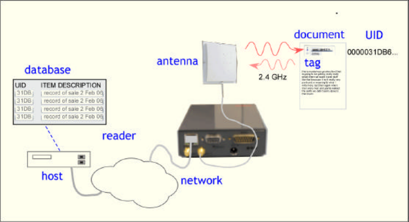
2.3 RFID System Quickstart
Radio Frequency Identification (RFID) uses electromagnetic waves to exchange information between a tag,
containing (at least) a number uniquely identifying that physical tag and by implication the object to which
it is attached, and a reader. RFID tags are analogous to bar codes, but can contain more information and
are more versatile.
The Hitachi America Ltd. HSS-MUR-300 reader operates in the US ISM frequency band from 2.4 to 2.483
GHz. This reader is compatible with tags that comply with Hitachi’s proprietary “µ-chip” standard. This
reader is not compatible with UHF (902-928 MHz) tags following the EPCglobal class 0 or class 1
(generation 1 or 2) standards or ISO-18000A or B, nor with HF (13.56 MHz) tags generally used in Smart
Cards, or LF (125/134 KHz) tags generally used in animal identification.
The Hitachi µ-chip is an RFID tag that operates in the 2.4-2.483 GHz band. Each chip is factory-encoded
with a unique identifier and cannot be re-written. With a unique identifier, these chips can be used to
authenticate currency and official documents and are suited to be embedded in paper. The HSS-MUR-300
reader is configured to use an Ethernet interface to communicate with a host computer; direct optically-
isolated I/O ports are also provided. A conventional serial port is available for specialized maintenance
tasks but is not used in normal operation. With an appropriate host and appropriate external antennas, a
stationary portal reader can be used to acquire the unique identification number (UID) of one compatible

Copyright© 2006 by Hitachi America Ltd. Subject to change without notice. This information is provided “as is”, no
claims of fit for purposes intended, merchantability or other are made. All trademarks, service marks, trade names and
logos are used in good faith and remain the property of their rightful owners. page 5
tag in its reading range. The “µ-chip” standard does not support anti-collision, and multiple tags
simultaneously present in the read range may not be reliably read.
A more detailed discussion of RFID technology can be found in the Appendix (section 10) .
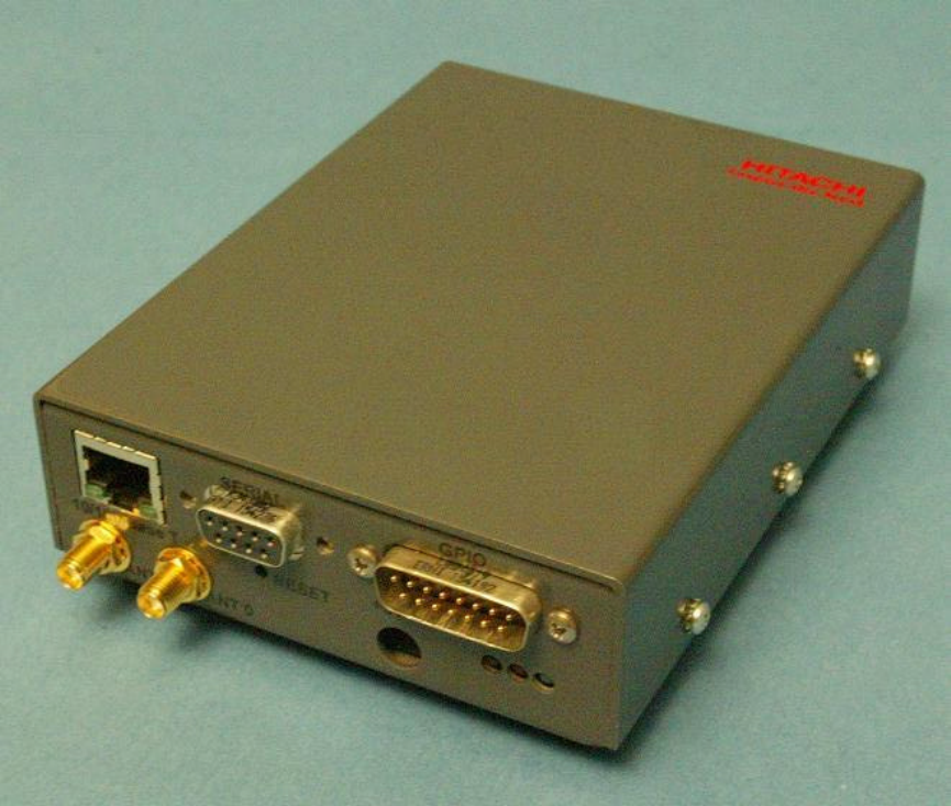
2.4 Product Description
The HSS-MUR-300 reader is a self-contained RFID reader configured for use at 2.4-2.483 GHz. Two
equivalent antenna connections, each using reverse-polarity SMA connectors, allow connection of one or
more external antennas. Each port can be connected to a linearly polarized patch antenna such as the
recommended MP2400XFPT/RPSMA, or to a similar circularly polarized antenna. Each antenna provides
both transmit and receive functions to communicate with a tag, and only one antenna is needed, but two
may be used. When two antennas are used, they are addressed in time sequence as requested by the host,
and are not used simultaneously. Communications with a host controller is achieved through a 10/100
BaseT (Ethernet) port employing a conventional RJ45 connector. Optically-isolated digital direct I/O is
also available. A serial port interface is provided solely for maintenance operations.
The HSS-MUR-300 RFID reader has 5 LEDs that provide status information for reader operation and
Ethernet connectivity. The following chart briefly describes each of the LEDs and its status.
Table 1 - HSS-MUR-300 RFID Reader LED Status
LED Description Location Color Operational Status
Ethernet Activity RJ-45 Ethernet Connector Yellow On – Transmitting or receiving
Off – No activity
Ethernet Link RJ-45 Ethernet Connector Green On –Connected
Off – No connectivity
Operating Ready Right Green On – Power On, Idle
Off – Processing a command or
reading tags
Read Activity Center Yellow On – Tag read
Off – No tags detected
Reader Operation Left Red On – Hardware fault.
Off – No fault detected
2.5 Unpacking and Inspection
Box Contents:
• HSS-MUR-300 Reader (1)
• AC power adaptor (1)
• external antenna and cable (1)
Copyright© 2006 by Hitachi America Ltd. Subject to change without notice. This information is provided “as is”, no
claims of fit for purposes intended, merchantability or other are made. All trademarks, service marks, trade names and
logos are used in good faith and remain the property of their rightful owners. page 6
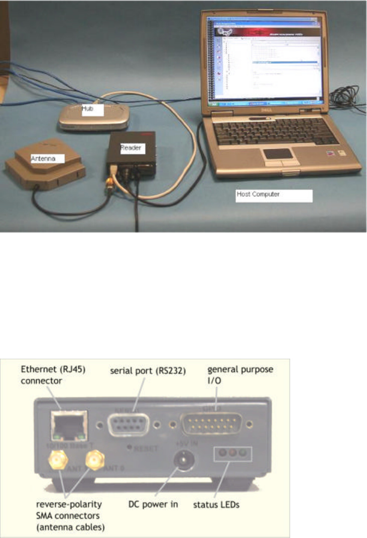
2.6 Product Installation
The HSS-MUR-300 reader is designed to be configured and installed by end users. Product users should
consult with Hitachi America Ltd. or their equipment vendor prior to modifying the installed configuration.
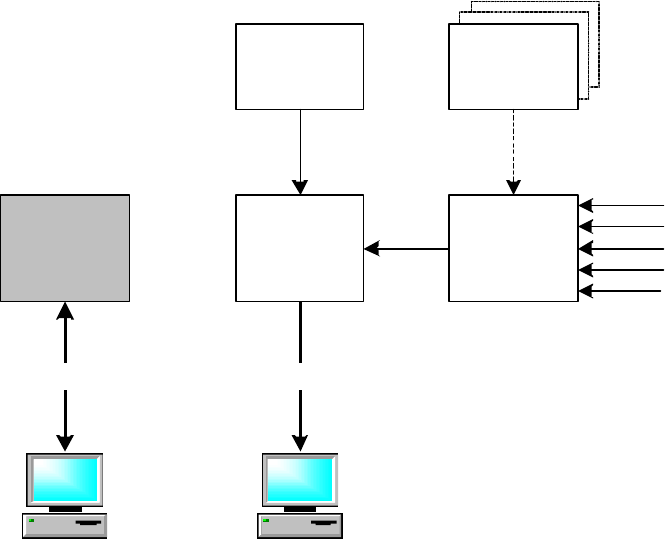
The HSS-MUR-300 reader uses an external antenna connected to the reader by a removable cable, and is
controlled over a conventional 10/100 BASE-T (“Ethernet”) network connection. A typical installed
configuration is shown below.
The HSS-MUR-300 reader should be installed in a location protected from physical impact. The reader
may support up to 2 external antennas. The antennas should not be located more than 1 meter (3 feet) from
the reader. The reader and antennas should not be located close to a strong source of RF interference such
as a cordless telephone or WiFi (IEEE 802.11) wireless local area network (WLAN) basestation. The
antennas should not have any conductive (metallic) obstructions within 20 cm in the direction in which tag
reading is to be performed.
The back panel of the HSS-MUR-300 reader is shown below. The reader is equipped with an Ethernet
connector, a serial port connector, a general-purpose I/O connector, antenna connectors, and a port for DC
power.
Copyright© 2006 by Hitachi America Ltd. Subject to change without notice. This information is provided “as is”, no
claims of fit for purposes intended, merchantability or other are made. All trademarks, service marks, trade names and
logos are used in good faith and remain the property of their rightful owners. page 7
A possible installation sequence is as follows:
1. Mount the reader to a secure, stable surface, with adequate clearance and air flow.
2. Attach the antenna cables to the relevant reverse-SMA connectors at the reader. You may
optionally terminate an unused antenna connection with a reverse SMA terminator, but this is not
required for normal operation.
3. Connect to the host or network. Use a conventional CAT5 or above cable to connect to an
Ethernet hub or switch; use a crossover cable to connect directly to a host computer.
4. Connect the +6 VDC power supply cable to the reader.
5. Place one appropriate RFID tag in front of one of the antenna at 5-25 cm distance.
At this point the reader should be ready for operation using the demonstration interface software, or other
custom control software.
3 Installation and Operation of demonstration software
The following description assumes the host computer is operating under Microsoft Windows XP; slightly
different screens will be visible if another operating system is employed.
3.1 Minimum System Requirements
This software requires a host computer running Microsoft Windows 98, NT, 2000 or XP, with a Pentium-
compatible PC and at least 128MB RAM, 50 MB available hard disk space, and 800x600 resolution or
higher. The configuration described presumes that an Ethernet network connection is available.
When powered up, the HSS-MUR-300 reader searches for a DHCP server; if found, the reader obtains an
IP address and subnet mask from the DHCP server, and is thereafter visible to other devices on the network
through a UDP ‘heartbeat’ message periodically declaring its presence. In order to obtain the IP address, it
is necessary to either access the reader through a serial connection (the console port), or detect the beacon
broadcast by the reader to the network. To use a serial connection, you need a host computer with a serial
port, or a USB-to-serial converter, and a serial communications utility such as Hyperterminal.
The reader is shipped from the factor with the default IP address:
192.168.1.200
If no DHCP server is available, the reader will retain this address. Communications can proceed directly
between a host and the reader, using an Ethernet hub or a crossover cable, if the host computer’s IP address
is on the same subnet as the default IP address.
3.2 Installation
3.2.1 Obtaining the IP Address of the Reader Using a Serial
Connection
To obtain the reader’s IP address manually, perform the following steps. The procedure assumes that a
network with a DHCP server is available.
1. Connect the reader to an appropriate network port (Ethernet or LAN connection) using a standard
(non-crossover) CAT5 cable.
Copyright© 2006 by Hitachi America Ltd. Subject to change without notice. This information is provided “as is”, no
claims of fit for purposes intended, merchantability or other are made. All trademarks, service marks, trade names and
logos are used in good faith and remain the property of their rightful owners. page 8
2. Connect the host computer directly to the reader using a serial cable (and USB converter if
needed).
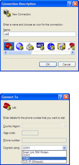
3. Start HyperTerminal or equivalent serial communications program. (The instructions below
assume Hyperterminal is used.)
4. You may be presented with a dialog box asking for phone connection information. Press Cancel.
A second dialog box may ask you to confirm the cancellation; press Yes and then when asked to
provide location information, press OK.
5. If you have not connected previously you may create a new connection and give it an appropriate
name. Press OK.
6. Again press Cancel, Yes, and OK in response to the (here irrelevant) requests for telephone
information. You will then be presented with a window containing the connection information for
the new connection. Select the appropriate COM port in the pop-up menu at the bottom. Click
OK.
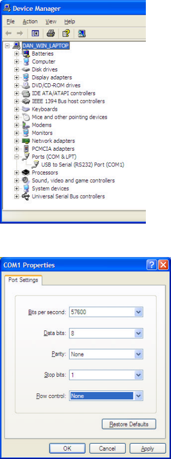
If you don’t know which COM port to address, go to Control Panel and select
System:Hardware:Device Manager. Click on the + symbol next to Ports (COM & LPT) to find
the serial ports enumerated.
Copyright© 2006 by Hitachi America Ltd. Subject to change without notice. This information is provided “as is”, no
claims of fit for purposes intended, merchantability or other are made. All trademarks, service marks, trade names and
logos are used in good faith and remain the property of their rightful owners. page 9
7. Configure the port settings as shown below: 57600 bits per second, 8 data bits, no parity, 1 stop
bit, and no flow control. Press OK.
8. Power up the reader. After a few seconds, Hyperterminal should show a set of messages
describing the operations taken by the Linux system as it boots up. Wait until the prompt “Please
press Enter to activate this console” appears. Press Enter.
9. You should now see a # prompt. Type ‘ifconfig’ <Enter>. A set of messages describing the
Ethernet configuration of the reader will appear. The first message is headed ‘eth0’. The second
line will read something like:
inet addr:144.172.2.30 Bcast:144.172.255.255 Mask:255.255.240.0
These three numbers are the internet (IP) address, broadcast address, and subnet mask of the
reader. Select and copy this line and paste into another document, or write down the addresses.
At this point you can optionally quit Hyperterminal and disconnect the serial port.
Copyright© 2006 by Hitachi America Ltd. Subject to change without notice. This information is provided “as is”, no
claims of fit for purposes intended, merchantability or other are made. All trademarks, service marks, trade names and
logos are used in good faith and remain the property of their rightful owners. page 10
3.2.2 Configuring the Reader Management Utility
Once you have obtained the reader’s IP address and subnet, subsequent communications take place using
the Ethernet network connection. The reader is configured to use the EPCglobal Reader Protocol and
Vendor Specific Commands to communicate with a host. The Reader Management Utility implements
these protocols and provides a convenient user interface.
The instructions below assume that the reader and the host computer are on the same subnet of a local area
network. When the reader and host are connected to neighboring ports on an Ethernet hub or switch this
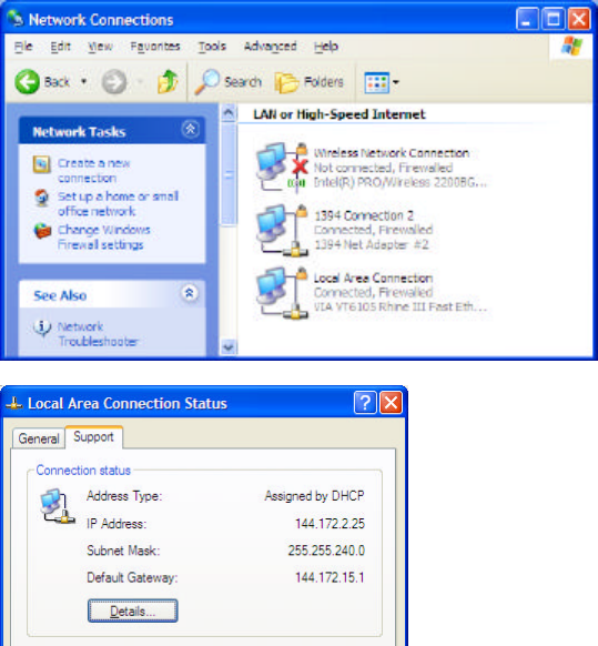
will almost certainly be the case. If in doubt, check the host computer IP address using Control Panel:
Network Settings and click on the active network connection’s Support tab.
If the first two dotted decimal numbers are the same for reader and host it is very likely they are on the
same subnet. (See any standard network reference for how to interpret the subnet mask to extract subnet
organization.) In most cases the host computer must be on the same subnet as the reader to communicate.
(It is in principle possible to assign a globally-routable IP address to the reader, if you wish to support
remote access without using a virtual private network (VPN). Such an arrangement involves important
security issues. Discuss this with your Information Technology staff or network administrator.)
Perform the steps below to install the Reader Management Utility.
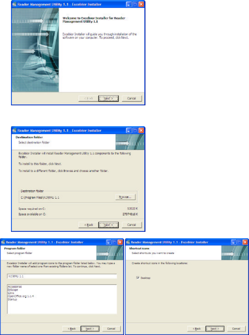
1. Run rmu_1.1_setup.exe, from the CD or its download location.
Copyright© 2006 by Hitachi America Ltd. Subject to change without notice. This information is provided “as is”, no
claims of fit for purposes intended, merchantability or other are made. All trademarks, service marks, trade names and
logos are used in good faith and remain the property of their rightful owners. page 11
2. Click Next. Select either a Personal or Common installation, and click Next.
3. If the default installation folder is not suitable, navigate to your preferred location, and then click
Next.
4. Use the default program icon name or enter your own and click Next.
5. Uncheck the Desktop selection if you do NOT wish to have a shortcut on your desktop to the
Reader Management Utility. Click Next.
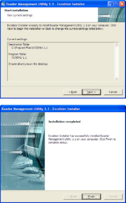
6. If the resulting configuration is what you wanted, click Next.
Copyright© 2006 by Hitachi America Ltd. Subject to change without notice. This information is provided “as is”, no
claims of fit for purposes intended, merchantability or other are made. All trademarks, service marks, trade names and
logos are used in good faith and remain the property of their rightful owners. page 12
7. Click Finish to complete setup.
You should now be able to start the Reader Management Utility from the desktop shortcut (if you chose to
install one) or from the Start:All Programs menu. It is now necessary to configure the Reader Management
Utility by providing the IP address of the reader (obtained in section 1.2.2.1 above) and that of your
computer.
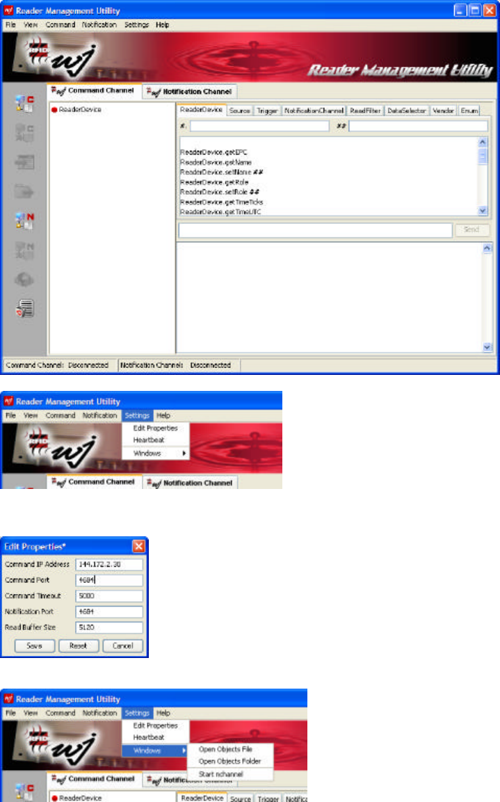
1. Start the Reader Management Utility. After a moment you should see the main screen.
Copyright© 2006 by Hitachi America Ltd. Subject to change without notice. This information is provided “as is”, no
claims of fit for purposes intended, merchantability or other are made. All trademarks, service marks, trade names and
logos are used in good faith and remain the property of their rightful owners. page 13
2. Select Settings:Edit Properties.
3. Set the Command IP address to the IP address of the HSS-MUR-300 reader obtained in section
1.2.2.1 above. Set the Command Port to 4684. Click Save. The host computer is now configured
to issue commands to the Reader.
4. We now need to configure the host computer to listen to the Notification Channel, to receive
information about tags read by the reader. Select Settings:Windows:Start nchannel.
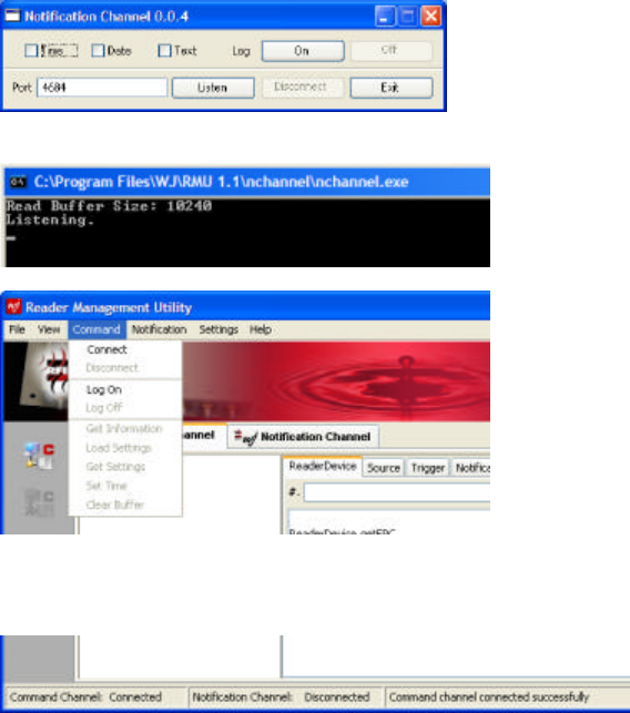
5. After a moment, the Notification Channel 0.0.4 window will appear. [Note that this is a separate
application, launched from Reader Management Utility.] Click Listen. You may see a security
message if you have a firewall active on your host computer; click Unblock to allow the
Notification Channel application to connect.
Copyright© 2006 by Hitachi America Ltd. Subject to change without notice. This information is provided “as is”, no
claims of fit for purposes intended, merchantability or other are made. All trademarks, service marks, trade names and
logos are used in good faith and remain the property of their rightful owners. page 14
Click on the Console window (the DOS-style text window): the last message there should be
‘Listening’.
6. Select Command:Connect.
After a moment, the status bar at the bottom of the window should say “Command Channel:
Connected”.
It is next necessary to configure the reader to communicate with the notification listener utility. These
configuration settings are contained in a text program called hitachi_settings.txt, provided in the load_files
directory on the distribution CD. You will need to save this program to your local hard disk and edit it with
a text editor such as Notepad. If you use a word processor such as Microsoft Word, you must be careful to
save the file as a text file, and not as an .rtf or .doc file.
1. Open hitachi_settings.txt in a text editor. Find the line reading:
NotificationChannel.create nc,000.000.000.000:4684
2. Replace the dotted decimal values with the IP address of your PC (the host computer, NOT the
HSS-MUR-300 reader). You can find this address by double-clicking on the active network
connection in the Control Panel: Network Connections window, and selecting the Support tab. An
example of the resulting edited line is shown below:
NotificationChannel.create nc,144.172.2.25:4684
3. Do not make any other changes in the file. Save the file to your local disk if you haven’t already
done so.
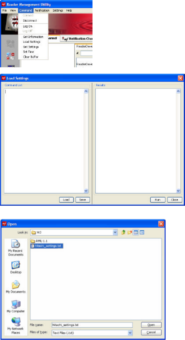
4. Bring up the Reader Management Utility window and select Command:Load Settings.
Copyright© 2006 by Hitachi America Ltd. Subject to change without notice. This information is provided “as is”, no
claims of fit for purposes intended, merchantability or other are made. All trademarks, service marks, trade names and
logos are used in good faith and remain the property of their rightful owners. page 15
5. In the Load Settings window, click the Load button.
Navigate to the location in which you saved hitachi_settings.txt and select the file. Click Open.
The contents of the file should appear in the Command List window.
Copyright© 2006 by Hitachi America Ltd. Subject to change without notice. This information is provided “as is”, no
claims of fit for purposes intended, merchantability or other are made. All trademarks, service marks, trade names and
logos are used in good faith and remain the property of their rightful owners. page 16
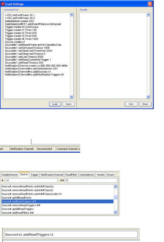
6. Click Run. The right-hand panel should show a COMPLETE message as each command is run.
7. The text window should display Notification channel connected. Note that the bottom of the
Reader Management Utility window will still indicate Notification Channel: Disconnected, as the
Notification Channel window is a separate application.
8. The final step is to add a read trigger to the source. Click the Source pane on the right-hand side
and navigate to the command Source#.addReadTriggers##. Enter s1 in the text box after #. and t1
in the text box after ##.
Click the command to insert it with placeholders filled in into the command box, and click Send.
At this point it should be possible to begin reading tags. Place a tag close to the antenna; note that if the
antenna is linearly polarized, the long axis of the tag must be along the direction of polarization.
3.3 Using the Demonstration software
The Reader Utility and Notification Channel utility are used to control the reader through the definition of
the EPCglobal Reader Protocol (version 1.1). The protocol defines the following classes of objects;
• ReaderDevice: base container for other objects in the model; includes at least one
CommandChannel
• Sources: contains one or more ReadPoints (antenna, barcode scan, etc.)
Copyright© 2006 by Hitachi America Ltd. Subject to change without notice. This information is provided “as is”, no
claims of fit for purposes intended, merchantability or other are made. All trademarks, service marks, trade names and
logos are used in good faith and remain the property of their rightful owners. page 17
o each source generally has the attributes MaxReadDutyCycle, ReadCyclesPerTrigger,
ReadTimeout
• Triggers: trigger a source to read, or a notification channel to get data from the report buffer
• ReadFilter: encapsulated in a source; defines binary bit masks for tags
• Events: changes in the tag list state:
o evGlimpsed: a specific tag is seen for the first time
o evObserved: a specific tag has been seen repeatedly over time > threshold [1]
o evLost: a specific tag is not seen for time > timeout
o evPurged: a specific tag is not seen for time > purge timeout [1]
o evNoEvents: the most recent trigger did not cause any tag events
• Channels: command or notification channel
• DataSelector: data to be sent; e.g. tag type, raw tag ID or URI, source name, trigger event, etc.
note 1: these events are not yet implemented in the Reader Management Utility
To read a tag, the reader needs a command channel, at least one source with at least one read point, and at
least one trigger for that read point. The read point is predefined to be assigned to one of the Antenna
objects corresponding to the two physical antennas. To report the tag events to the host, the object also
needs at least one notification channel, and a data selector with at least one data item (such as the tag ID)
selected for reporting. All these objects should have been configured when you loaded the recreate_nc.txt
file. If some of the objects are missing, you can use the Reader Management Utility to add them. You can
also change the configuration of the reader to suit your requirements; e.g., you can add a continuous trigger
or a timed trigger, or you can set up a filter that reports only tags that have been observed (read multiple
times) rather than glimpsed (read once).
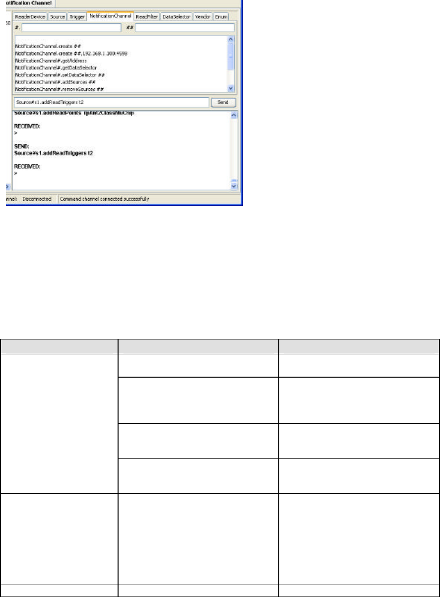
The Reader Management Utility provides a pane on the left side to display the reader object’s current state,
a set of panes on the right side to send Reader Protocol commands to the reader to change its state, and a
set of menu commands for other specific purposes.
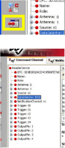
To find the current configuration of the reader’s object model, click on the Get Reader Information button.
The left-hand window will then be populated with a tree diagram depicting the state of the virtual reader.
Click on the [+] symbols to expand the tree any object and show what objects it contains.
You can issue Reader Protocol commands to the reader using the right-hand panels.
Copyright© 2006 by Hitachi America Ltd. Subject to change without notice. This information is provided “as is”, no
claims of fit for purposes intended, merchantability or other are made. All trademarks, service marks, trade names and
logos are used in good faith and remain the property of their rightful owners. page 18
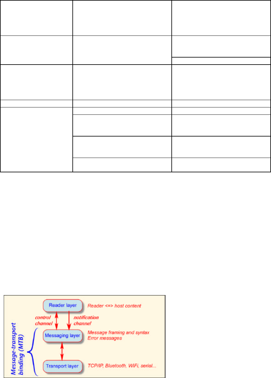
Commands can be directly entered into the text box in the center of the pane, and sent to the reader by
clicking Send. Alternatively, the tabs can be used to navigate through the categories of commands. Each
supported command is provided with placeholders ‘#.’ and ‘##’ for the parameters of the command. The
placeholders can be filled by inserting the appropriate values in the ‘#.’ and ‘##’ text boxes at the top of the
pane. When a command is successfully received the response box at the bottom will show RECEIVED:
followed by any return data and the > caret.
3.4 Software / Communications Troubleshooting
symptom likely cause corrective action
no connection make sure serial cable and (if used)
USB adaptor are plugged in
wrong COM port check the SYSTEM: DEVICE
MANAGER: HARDWARE control
panel to see if the desired port is
displayed
USB adaptor isn’t shown make sure a driver for the USB
adaptor has been loaded on your host
computer
serial communications
software doesn’t see the
reader
wrong parameters ensure you’ve entered the
communications parameters
requested
ifconfig returns 000-value
or unexpected IP
addresses
no DHCP server make sure there is a DHCP server
connected to the network connection
the reader is using. For example,
hook a laptop or desktop computer to
the same network port and renew
your DHCP lease in the TCP control
panel; make sure you get a new IP
address after 15-30 seconds.
Command channel fails to
incorrect reader IP address or port check value in Settings menu
Copyright© 2006 by Hitachi America Ltd. Subject to change without notice. This information is provided “as is”, no
claims of fit for purposes intended, merchantability or other are made. All trademarks, service marks, trade names and
logos are used in good faith and remain the property of their rightful owners. page 19
connect reader and host on different subnets check IP address of host; for most
subnets it should differ only in the
last dotted decimal block from the
reader IP address; if in doubt see
your network administrator
run recreate_nc.txt , after changing
the IP address listed in that file to the
address of your host computer
Notification channel fails
to connect
no notification channel created
reboot reader
Run hitachi_settings.txt
causes an ABORT
message to appear
Some objects to be created by
hitachi_settings are already present. Issue the command
ReaderDevice.resetToDefaultSettings
to restore the reader to its initial state,
and then reload and rerun
hitachi_settings.txt
no source object defined add a source
no read point add a read point; note that the read
point must be assigned both to a
source and to an antenna
no data selector add a data selector and a data item
(usually tagID) for the selector to
select
Tags are not read when
placed near the reader
no trigger add a trigger; note that the trigger
must also be placed within the source
4 Overview of Reader Communications and
Configuration Under EPCglobal Reader Protocol
The HSS-MUR-300 communicates based on the EPC Global Reader Protocol 1.1 (working draft dated: 06-
27-2005) in development by EPC Global Inc.
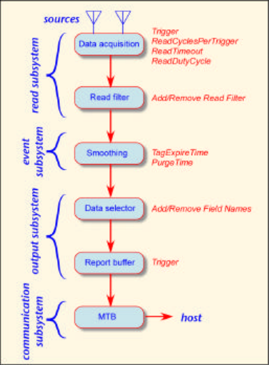
The Reader Protocol communications approach is based on layering message channels on top of a transport
channel. The control channel and notification channel exchange information with a messaging layer, which
provides the necessary syntax for the transport channel employed. The combination of the messaging layer
and the selected transport layer forms a Message Transport Binding (MTB). The HSS-MUR-300 uses a
TCP/ Text Message MTB, so the primary transport mechanism is a TCP/IP connection, typically created
over an Ethernet (IEEE 802) local area network.
Copyright© 2006 by Hitachi America Ltd. Subject to change without notice. This information is provided “as is”, no
claims of fit for purposes intended, merchantability or other are made. All trademarks, service marks, trade names and
logos are used in good faith and remain the property of their rightful owners. page 20
While this architecture is not required by the standard, it is expected that most reader subsystems will be
configured with a read subsystem, an event subsystem, and output subsystem, and a communications
subsystem.
Each acquisition of tag data from a single source is a read cycle. The host can specify the frequency and
number of read cycles and trigger conditions. Triggers cause reads to flow to the report buffer but not
necessarily to the host. Filters are bitwise masks used to assist tag singulation.
Event smoothing reduces the amount of data in upper layers by recording only important events. The
reader maintains a tag list describing all reads by all sources; changes in the tag list produce events:
evGlimpsed: a specific tag is seen for the first time
evObserved: a specific tag has been seen repeatedly over time > threshold
evLost: a specific tag is not seen for time > timeout
evPurged: a specific tag is not seen for time > purge timeout
These events are transitions between the states:
isUnknown
isGlimpsed
isObserved
isLost
Data selection determines what data fields are to be reported and manages the report buffer queue. The
report buffer provides storage for the output of the data selector. The host can request synchronous
delivery of all events, or triggers can initiate asynchronous data transfer to host. The buffer is cleared after
data is delivered to host. The message transport binding is responsible to bind the data to a specific
transport protocol (here TCP/IP) and send it to the host.
The object model includes the objects:
• ReaderDevice: base container for other objects in the model; includes at least one
CommandChannel
• Sources: contains one or more ReadPoints (antenna, barcode scan, etc.)
Copyright© 2006 by Hitachi America Ltd. Subject to change without notice. This information is provided “as is”, no
claims of fit for purposes intended, merchantability or other are made. All trademarks, service marks, trade names and
logos are used in good faith and remain the property of their rightful owners. page 21
o each source generally has the attributes MaxReadDutyCycle, ReadCyclesPerTrigger,
ReadTimeout
• Triggers: trigger a source to read, or a notification channel to get data from the report buffer
• ReadFilter: encapsulated in a source; defines binary bit masks for tags
• Events: changes in the tag list state:
o evGlimpsed: a specific tag is seen for the first time
o evObserved: a specific tag has been seen repeatedly over time > threshold
o evLost: a specific tag is not seen for time > timeout
o evPurged: a specific tag is not seen for time > purge timeout
o evNoEvents: the most recent trigger did not cause any tag events
• Channels: command or notification channel
• DataSelector: data to be sent; e.g. tag type, raw tag ID or URI, source name, trigger event, etc.
These objects and their implementation in the HSS-MUR-300 are described in more detail below.
4.1 Message Channels
The HSS-MUR-300 uses a command channel and notification channel; configuring and managing the
reader via the command channel, receiving data from the reader via the notification channel. Once
configured, the reader can function as a stand-alone reader that does not require outside action. The
command and notification channels communicate via an Ethernet link. The reader supports one command
channel and one notification channel. The command channel host can be different from the notification
channel host.
4.2 Command
The command channel carries all requests sent by the host to the reader as well as the responses to these
requests from the reader to the host. All messages exchanged over the command channel follow a
request/response pattern. The host acts as a client and connects to the reader, which acts as the server.
4.3 Notification
The reader sends data it collects by means of a notification channel. This channel is a talk-only link for the
reader and a listen-only link for the host or management software. The user assigns an IP address for the
notification channel to send data to the host and the host is able to listen to receive the notification channel.
The notification channel carries messages issued asynchronously by the reader to the host. The reader
sends messages over the notification channel autonomously.
Copyright© 2006 by Hitachi America Ltd. Subject to change without notice. This information is provided “as is”, no
claims of fit for purposes intended, merchantability or other are made. All trademarks, service marks, trade names and
logos are used in good faith and remain the property of their rightful owners. page 22
For the notification channel, the reader acts as a client and connects to a host, which acts as a server.
Command
Host Notification
Host(s)
Notification
Channel
Command
Channel
TCP TCP
Server
Server
Client
Client
Source(s)
Trigger0
(Continuous, ...)
Trigger1
(Timer, ...)
rpAnt1Class0
rpAnt1Class1
rpAnt4ClassIso
.
.
.
4.4 Configurable Reader Components
The HSS-MUR-300 RFID Reader is designed to be user-configurable. The “EPC Global Reader Protocol
1.1 (working draft dated: 06-27-2005) ratified by EPC Global Inc.” specification identifies configurable
components of compliant readers using a well defined structure of objects. The relationship of the various
objects is intended to provide configuration flexibility, and a defined hierarchy which supports
configurations ranging from very simple “Read on Command” operation, to sophisticated autonomous tag
reading and tag data reporting operations under timer or externally triggered control.
The configurable objects (except for the Reader Device) are identified by name (up to 64 characters). The
HSS-MUR-300 RFID Reader supports the following configurable object types:
• Reader Device – The highest level component of the reader. Controls access to all of the other
reader objects. The ReaderDevice object is the base container for most other objects. It represents
the reader and contains several attributes used to manage the reader.
• Source – Parameters and the grouping of reader objects configured to perform a single tag read
and report operation. A Source is a logical entity that can encapsulate one or more input sensors
called read points. A read point is any physical entity that is capable of acquiring data (i.e. an
antenna). A reader can have multiple Sources. A Source can have multiple read points.
• Triggers – A Trigger can be contained by a Source where they act as read triggers. A read trigger
causes the reader to acquire data from the Trigger’s associated Source. Triggering a read causes
data to flow from the Source to a report buffer, but it does not cause any communication with the
host. A notification channel uses a trigger known as a notification trigger. A notification trigger
causes the reader to send the entire content of the report buffer, which is associated with this
trigger’s notification channel. There are currently four types of Triggers: timer, IO edge, IO
Value, and continuous.
o Continuous – the activity is triggered as rapidly as possible. For notificationTriggers, this
means that a new event shall be sent whenever a new event appears in the report buffer.
Copyright© 2006 by Hitachi America Ltd. Subject to change without notice. This information is provided “as is”, no
claims of fit for purposes intended, merchantability or other are made. All trademarks, service marks, trade names and
logos are used in good faith and remain the property of their rightful owners. page 23
o Timer – the activity is triggered at regular time intervals.
o IO Edge – the activity is triggered by a signal transition at an IO port.
o IO Value – the activity is triggered by a value (using multiple GPIO pins) match at the IO
port.
• Read Point – Controls the reading of a single tag type using a single TX/RX antenna pair.
• Read Filter – Defines the specific Tag Identities to be included in (or exc luded from) the tag event
smoothing and Tag Event generation operations.
• Notification Channel – A TCP/IP port Ethernet connection used to send tag data event report
messages to a host computer.
• Data Selector – Defines the field names data, and the tag event data for event types to be sent in
the Tag Data Event Report messages for a ReadIDs command, or for the Notification Channel.
• Field Names – Defines the Fields (by name) for which a value is to be reported in each Tag Data
Event Report message associated with the Data Selector.
• Event Type – Defines which Tag Identities with the corresponding Event Type(s) are to be
reported in each tag data read Report message associated with the Data Selector. Only Tag ID
events matching the specified Event Type(s) are included in the report.
Read and Notification Trigger – Definition of automatic control mechanisms to provide autonomous reader
operation for tag reading and report generation of tag events.
The following sections provide a simple set of example commands for configuring the HSS-MUR-300
RFID reader.
4.4.1 Reader Identification
Assign the reader a unique identifying name ‘RFID Reader’:
Format: ReaderDevicesetName [Name]
Example: ReaderDevice.setName RFID Reader
4.4.2 Data Selector
Create a data selector ‘DS1’
Format: DataSelector.create [Name]
Example: DataSelector.create DS1
4.4.2.1 Data Selector Field Name
Define the report field name for tag data read reports:
Format: DataSelector#[Name].addFieldNames [Name1][Name2]…[NameN]
Example: DataSelector#DS1.addFieldNames TagID,ReaderID,ReaderNowTick"
4.4.2.2 Event Report
Define event types for tag data event reports:
Format: DataSelector#[Name].addEventFilters [FilterName],[FilterName]
Example: DataSelector#DS2.addEventFilters evGlimpsed,evLost
4.4.3 Read Filter
Create an include read filter ‘I800X’ that Tag IDs that begin with ‘800x8004’ (where ‘x’ is any
digit) are processed:
Copyright© 2006 by Hitachi America Ltd. Subject to change without notice. This information is provided “as is”, no
claims of fit for purposes intended, merchantability or other are made. All trademarks, service marks, trade names and
logos are used in good faith and remain the property of their rightful owners. page 24
Format: ReadFilter.create [Name],[TagID],[Boolean]
• "ReadFilter.create I800X,80008004,FFF0FFFF,true"
Create an exclude read filter (‘X8001’) that Tag IDs that begin with ‘8001’ will be excluded:
• "ReadFilter.create X8001,8001,FFFF,false"
4.4.4 Source
Create the source object ‘dock_door’:
Format: Source.create [Name]
Example: Source.create dock_door
4.4.4.1 Read Point
Assign Read Points ‘rpAnt1ClassMuChip’ (read µ-Chips using Antenna 1) which identify the
class of tags, and the Antenna for a single tag data read:
Format: Source#[Source].addReadPoints rpAnt[Antenna][Tag Class]
Example: Source#dock_door.addReadPoints rpAnt1ClassMuChip
Issue a raw read command to perform a single tag data read operation with all tag data reported
on the command channel DS1 to control the report formatting):
Format: Source#[Source].rawReadIDs [Data Selector]
Example: Source#dock_door.rawReadIDs DS1
4.4.5 Triggers
4.4.5.1 Creating Triggers
Create a continuous trigger called Notify1 to generate autonomous Tag Data Event Reports:
Format: Trigger.create [Name],[Type]
Example: Trigger.create Notify1,Continuous
Create a timed trigger that causes autonomous tag data read operations every 200 milliseconds:
Format: Trigger.create [Name],[Type],[Interval]
Example: Trigger.create ReadTimer 200mSec,Timer,200
Create an I/O Edge Trigger that causes autonomous tag data read operations as the result of a
Rising Edge on Digital I/O Pin 1 (Port Number is always 1):
Format: Trigger.create [Name],[Type],[Edge],1,[Pin]
Example: Trigger.create ReadEdgeRising,IOEdge,rising,1,1
Create an I/O Value Trigger that causes autonomous tag data read operations as the result of a
configurable value(s) are detected on the Digital I/O Pins (Port Number is always 1). The
Mask parameter is optional, it is bitwise anded with the port data before comparing to the
mask:
Format: Trigger.create [Name],[Type], 1, [Value], [Mask]
Example: Trigger.create ReadValue, IOValue, 1, 0002, 0002Read Trigger
Add ‘ReadTimer‘ to ‘dock_door’ to read tags autonomously:
Copyright© 2006 by Hitachi America Ltd. Subject to change without notice. This information is provided “as is”, no
claims of fit for purposes intended, merchantability or other are made. All trademarks, service marks, trade names and
logos are used in good faith and remain the property of their rightful owners. page 25
Format: Source#[Source].addReadTriggers [Trigger]
Example: Source#dock_door.addReadTriggers ReadTimer
Add the ‘ReadEdge‘ read trigger to cause autonomous tag data read operations when a rising
edge signal is detected on digital I/O pin 1:
Format: Source#[Source].addReadTriggers [Name] [I/O Pin] [Edge]
Example: Source#dock_door.addReadTriggers ReadEdge 1 Rising
Add read filter ‘I800X’ to cause only tags that begin with ‘800x8004’ (where ‘x’ is any digit) to
be processed:
Format: Source#[Source].addReadFilters [Filter]
Example: Source#front_door.addReadFilters I800X
4.4.6 Message Channels
4.4.6.1 Command Channel
In order to modify the IP Address, NetMask, and Port Number for the HSS-MUR-300 RFID
Reader Command Channel, it is necessary to set Administrative Mode and then issue the
command to set the new Command Channel values:
Enter Admin mode:
Format: +HAL:adminMode [Password]
Example: +HAL:adminMode HALcomm
Change the reader’s IP address:
Format: +HAL:setIPaddr [Type],[IP Address],[NetMask],[Port]
Example: +HAL:setIPaddr static,192.168.1.200,255.255.255.0,4599
4.4.6.2 Notification Channel
Create the notification channel ‘NC1’ for autonomous tag data event reports:
Format: NotificationChannel.create [Channel Name],[IP Address]:[Port]
Example: NotificationChannel.create NC1,192.168.1.1:4684
Assign the data selector ‘DS1’ to the notification channel ‘NC1’:
Format: NotificationChannel#[Channel Name].setDataSelector [Selector Name]
Example: NotificationChannel#NC1.setDataSelector DS1
Assign the source ‘dock_door 1’ to the notification channel ‘NC1’
Format: NotificationChannel#[Channel Name].addSources [Source]
Example: NotificationChannel#NC1.addSources dock_door 1"
Assign the continuous notification trigger ‘Cont’ to the notification channel ‘NC1’:
Format: NotificationChannel#[Channel Name].addNotificationTriggers[Trigger]
Example: NotificationChannel#NC1.addNotificationTriggers Cont
These commands capture autonomous tag data events from ‘dock_door 1’ and tag data event
reports are sent on the notification channel. The ‘DS2’ Data Selector to controls the report
format.
Copyright© 2006 by Hitachi America Ltd. Subject to change without notice. This information is provided “as is”, no
claims of fit for purposes intended, merchantability or other are made. All trademarks, service marks, trade names and
logos are used in good faith and remain the property of their rightful owners. page 26
4.4.7 Vendor Specific Commands (VSC)
Set power level for antenna 1 at 27dBm:
Format: .setFwdPower [Power(dBm)],[Antenna]
Example: .setFwdPower27,1
Get power level on antenna 1:
Format: .getFwdPower (Antenna)
Example: .getFwdPower 1
Set a static IP address, 192.168.0.1, using port 4684:
Format: .setIPaddr [Type],[Address],[Subnet],[Port]
Example: .setIPaddr static,192.168.0.1,255.255.255.0,4684
Valid Types: DHCP, Static
Note: the reader automatically reboots after an IP address type or value change
Set the heartbeat with period 15 for port 4500
Format: .setHeartbeat [Boolean],[Period],[Port]
Example: .setHeartbeat true,15,4500
Set the administration mode password to ‘HAL’
Format: setPassword [password]
Example: setPassword HAL
Set the reader to administration mode
Format: adminMode [password]
Example: adminMode [HAL]
Copyright© 2006 by Hitachi America Ltd. Subject to change without notice. This information is provided “as is”, no
claims of fit for purposes intended, merchantability or other are made. All trademarks, service marks, trade names and
logos are used in good faith and remain the property of their rightful owners. page 27
Copyright© 2006 by Hitachi America Ltd. Subject to change without notice. This information is provided “as is”, no
claims of fit for purposes intended, merchantability or other are made. All trademarks, service marks, trade names and
logos are used in good faith and remain the property of their rightful owners. page 28
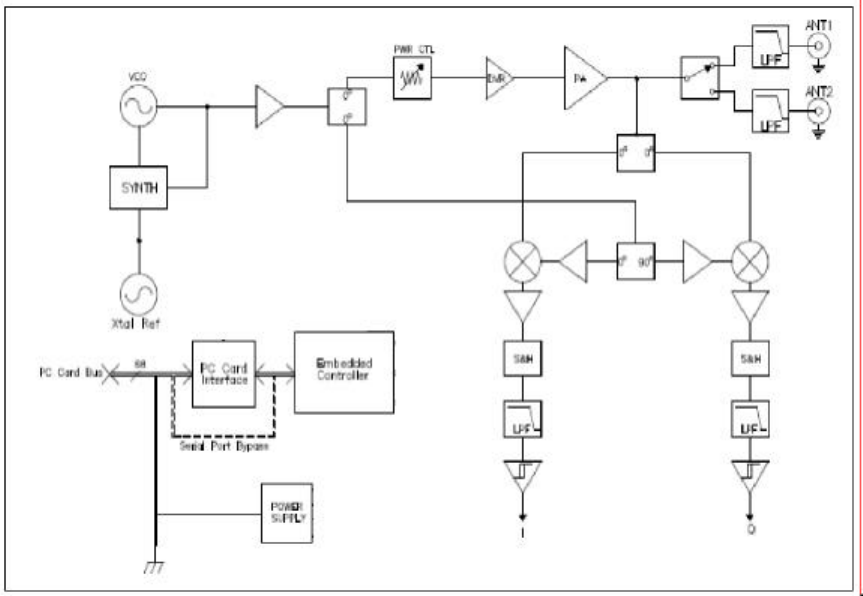
5 SR2500 RFID Reader Theory of Operation
The HSS-MUR-300 RFID reader consists of a transmitter and receiver, both employing the same local
oscillator and direct up- and down-conversion to/from the carrier frequency, configured for operation
within the US Industrial Scientific and Medical (ISM) band at 2.4-2.483 GHz. The transmitter signal both
provides power to passive tags and delivers commands to the tags. The system is thus full-duplex in the
sense that the transmitter continues to operate during reception of tag signals, but half-duplex in terms of
data transmis sion, since when tag data is being received the transmitted signal is unmodulated CW. In a
typical exchange, the transmitter first powers up and sends a CW signal to provide power to tags in the read
zone. Then a baseband on-off-keyed modulation, appropriately filtered, is imposed on the CW signal with
a mixer. The reader data provides tags with synchronization information, and requests tags to transmit their
unique IDs. After a command is given, the transmitter continues to transmit unmodulated CW power at the
carrier frequency; this CW signal both provides power to operate the tag’s integrated circuit, and provides
the RF signal that the tags backscatter to send their signals back to the reader. The proprietary µ-chip tags
do not support anti-collision algorithms, and do not support writing new identifying numbers or other user
information to the tags.
The backscattered signal is mixed to baseband using the same VCO signal employed by the transmitter; the
HSS-MUR-300 reader is a homodyne radio. In-phase / quadrature (I/Q) demodulation is employed in
order to ensure that the baseband signal can be received despite variations in the absolute phase of the
reflected carrier. (Without this provision, depending on the exact separation of the tag and reader antenna,
the cable lengths, and other factors that cannot be controlled, the reflected signal would at times be in
quadrature with the signal from the VCO, so that the mixer would produce no baseband output.) The
outputs of the two mixers are filtered and amplified and then demodulated to extract the reflected signal
from the tags. After each command set the power shuts down while processing of the commands proceeds.
The nominal channel spacing is 1 MHz, providing 75 channels (with guard bands) within the ISM band. In
Copyright© 2006 by Hitachi America Ltd. Subject to change without notice. This information is provided “as is”, no
claims of fit for purposes intended, merchantability or other are made. All trademarks, service marks, trade names and
logos are used in good faith and remain the property of their rightful owners. page 29
accordance with FCC regulations, the carrier frequency periodically ‘hops’ in a pseudo-random fashion
over the ISM band to avoid persistent interference with other unlicensed users.
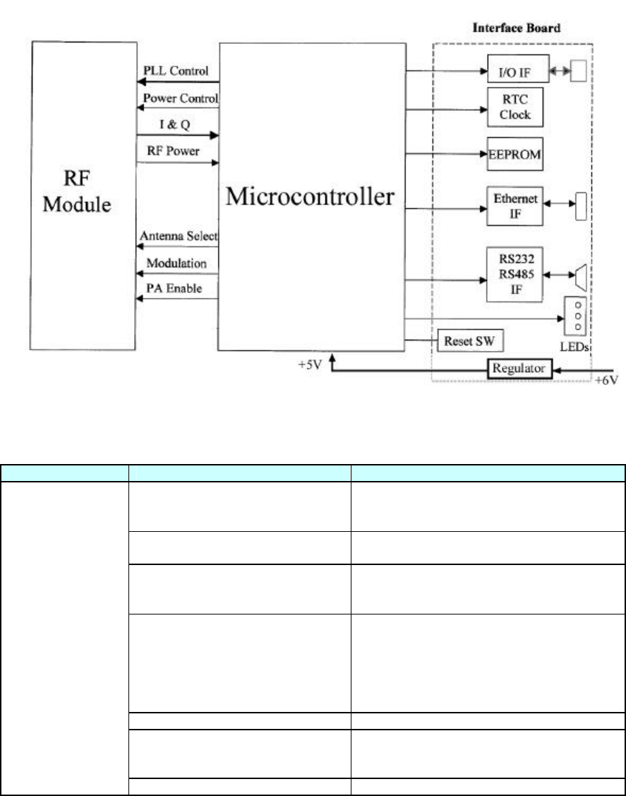
The overall system consists of the RF module, a controller, and interfaces to serial and Ethernet ports for
communication with a host computer or network.
6 Troubleshooting
Symptom Probable Cause Corrective Action
No DC power verify DC power block is plugged in and
connected to reader; operating / ready
ndicator LED red
No antenna connection verify antenna is snugly connected to reader
output and (if present) other adaptors
Wrong antenna assignment verify that the read point being triggered
corresponds to the antenna port physically
connected to an antenna presented with tags
Wrong tag orientation long axis of tag antenna must be
perpendicular to reader-to-tag direction; if
linearly polarized antenna is used, long axis
must be oriented along polarization (i.e. tag
must be horizontal if horizontal polarization
is used); see section 1.9.2.2
Tag too far read range is limited to approximately 30 cm
Power set too low read range will fall approximately 1 dB
(factor of 0.9) for each 2 dB reduction in
transmit power; see table yy.yy
Tag is not read
Defective tag substitute another tag
Copyright© 2006 by Hitachi America Ltd. Subject to change without notice. This information is provided “as is”, no
claims of fit for purposes intended, merchantability or other are made. All trademarks, service marks, trade names and
logos are used in good faith and remain the property of their rightful owners. page 30
tag environment tags cannot be read when resting directly on
metal object or object containing aqueous
fluids; provide 1-2 cm spacing from such
objects
reader antenna environment no metal obstacles should be present between
reader antenna and tag
Tag read
sporadically
interference check vicinity for likely interferers, including
active WiFi (802.11) client or basestation,
active Bluetooth client or basestation,
cordless telephone operating at 2.4 GHz band
7 Technical specifications
PHYSICAL:
Parameter Specification
Dimensions 140 mm (5.50”) Length x 105 mm (4.13”) Width x 32 mm (1.25”) Height
Weight 0.545 Kgm (1 lb 3.2 oz)
Chassis Material Aluminum
Antenna ports 2
Antenna connectors reverse-polarity SMA
Network ports 1 (RJ45)
Serial communications 1 (Female DB9)
GPIO male DB15
Power 2.1 mm ID (pin positive); 5.5 mm OD (GND), 12 mm insert length
ELECTRICAL / PERFORMANCE:
Parameter Specification
DC power 6 VDC, 24 watts; recommended power supply : CVI PN DTS060400UDC
Operating Frequency US ISM band (2.4 –2.483 GHz)
Frequency-hopping: 75 channels at 1MHz spacing
Maximum transmit power 28.0 dBm
Protocol support Hitachi µ-chip
Read range 30 cm typical
Operating temperature -10 to 55°C (-14 to 132°F)
Recommended antennas MP2400XFPT/RPSMA (linear polarized)
HG2409PCR (RHCP) or HG2409PCL (LHCP)
Antenna Max Gain 8.5 dBi, 8.0 dBiC; 1 meter (3 foot) cable; see note [1]
COMMUNICATIONS:
Parameter Specification
network port 10/100 BASE T (Ethernet)
serial port RS232
host interface complies with EPCGlobal draft Reader Host Specification 6-27-05
GPIO see note [2]
HARDWARE / OS:
Parameter Specification
Processor Cirrus Logic EP9302 ARM9 Core
Memory 32MB Flash; 32MB SDRAM
Operating System Debian Linux Kernel V2.4
Copyright© 2006 by Hitachi America Ltd. Subject to change without notice. This information is provided “as is”, no
claims of fit for purposes intended, merchantability or other are made. All trademarks, service marks, trade names and
logos are used in good faith and remain the property of their rightful owners. page 31
[1] Antennas of similar type (panel or patch) and the same or lower gain may be substituted for the
recommended antenna. Antenna gains listed above do not include 0.6 dB cable loss, which must be added
to published antenna gains to calculate effective antenna gain. Use of antennas with higher effective gain
than the recommended antenna may lead to failure of the unit to comply with applicable standards for
unlicensed operation in the United States.
[2] The HSS-MUR-300 RFID Reader provides 4 externally accessible digital inputs and 4 outputs. These
inputs are optically isolated (positive or negative, up to 30V differential) for external event sensing. The 4
digital outputs (on/off MOSFET switch operation up to 30V differential) control external devices.
8 Notices
8.1 RFID limitations
Communication between tags and readers at 2.4 GHz is a complex phenomenon depending on details of
the environment surrounding the tags and reader(s) as well as the equipment being used. Some
environmental aspects (such as tag placement and orientation) may be controllable by the user; others (such
as reflections of the RF radiation by ambient objects) are generally not. Careful installation and testing,
and development and adherence to appropriate operating procedures, are indispensable for successful
implementation of RFID. Hitachi America Ltd. makes no representation or warrantee that any specific
configuration of RFID tags and readers will provide any given performance characteristics.
8.2 Safety
Any use of this equipment with antennas or cabling installed outdoors or otherwise exposed to inclement
weather must avoid proximity with power lines or other high-voltage conductors, and provide for proper
grounding and lightning arresting devices to protect the equipment user in the event of a lightning strike.
See National Electrical Code (NEC) requirements articles 725, 800, and 810 for further information.
Do not operate the stationary portal readers in any area where critical safety equipment may be sensitive to
RF interference, such as medical or life support equipment.
Do not operate the stationary portal readers on board any aircraft in flight, or at any other time when
operation of radio devices such as cellular phones is prohibited.
Personnel should not be closer than 20 cm (8 inches) from any Stationary portal reader antenna for
prolonged periods of time. See FCC bulletins 56 and 65 for further information on electromagnetic field
exposure.
8.3 Limitation of liability
The information in this manual is subject to change without notice and does not represent a commitment on
the part of Hitachi America Ltd. Hitachi America Ltd., specifically disclaims liability for any and all
direct, indirect, special, general, incidental, consequential, punitive or exemplary damages, including but
not limited to loss of profits, revenue, or anticipated loss of profits or revenue, arising out of the use or
inability to use any Hitachi America Ltd. product, even if Hitachi America Ltd. has been advised or the
possibility of such damages or they are foreseeable, or for claims by any third party.
8.4 Patents
Portions of the products described in this manual may be covered by granted or currently-pending US and
foreign patents.

Copyright© 2006 by Hitachi America Ltd. Subject to change without notice. This information is provided “as is”, no
claims of fit for purposes intended, merchantability or other are made. All trademarks, service marks, trade names and
logos are used in good faith and remain the property of their rightful owners. page 32
8.5 Copyright notice
The contents of this document are the property of Hitachi America Ltd., except where otherwise noted.
Individuals who have purchased or otherwise legally acquired the stationary portal reader hardware units
described in this document are expressly permitted to make copies of the document, in electronic or paper
form, for personal, backup, and archival use. Brief segments may be excerpted and used with attribution
for descriptive purposes in commentaries, reviews, or other informational documents. All other
reproduction in whole or in part is expressly prohibited without the consent of the copyright owner.
Copyright 2006 by Hitachi America Ltd.
8.6 Comments and feedback
Comments and feedback on this manual or the HSS-MUR-300 reader are welcomed:
By phone: 1-800-WJ1-4401 (951-4401) or (972) 705-2313
By email: RFID.info@wj.com
9 Regulatory Compliance
9.1 FCC Statement
This equipment has been tested [PENDING AT THE TIME OF THIS WRITING!] and found to
comply with the limits for a Subparts B Class A digital device, pursuant to Part 15 of the FCC
Rules. These limits are designed to provide reasonable protection against harmful interference in
a residential installation. This equipment generates, uses and can radiate radio frequency energy
and, if not installed and used in accordance with the instructions, may cause harmful interference
to radio communications. However, there is no guarantee that interference will not occur in a
particular installation. If this equipment does cause harmful interference to radio or television
reception, which can be determined by turning the equipment off and on, the user is encouraged
to try to correct the interference by one or more of the following measures:
-- Reorient or relocate the receiving antenna.
-- Increase the separation between the equipment and receiver.
-- Connect the equipment into an outlet on a circuit different from that to which the receiver is
connected.
-- Consult the dealer or an experienced radio/TV technician for help.
NOTE: Changes or modifications not expressly approved by Hitachi America Ltd. could void the
user's authority to operate the equipment described in this manual.
9.1.1 RF Radiation Exposure Statement
These devices comply with FCC radiation exposure limits set forth for an uncontrolled environment, and
users must follow specific operating instructions for satisfying RF exposure compliance. To comply with
FCC RF exposure requirements, a separation distance of at least 20cm must be maintained between the
antenna of this device and all persons. This device must not be co-located or operating in conjunction with
any other antenna or transmitter.
Copyright© 2006 by Hitachi America Ltd. Subject to change without notice. This information is provided “as is”, no
claims of fit for purposes intended, merchantability or other are made. All trademarks, service marks, trade names and
logos are used in good faith and remain the property of their rightful owners. page 33
10 APPENDIX
10.1 RFID operating principles
Radio-frequency identification (RFID) is an auto-identification technology, similar in concept to other
common auto-identification technologies such as bar code scanners, magnetic strip readers, or magnetic ink
readers. Like other auto-ID techniques. RFID associates an identifying number with a physical object. In
RFID, the unique identifying number (UID or, as will be explained below, EPC) is incorporated in a
special system, an RFID transponder (often simply known as a tag). An RFID Interrogator (usually
known as a reader) is used to obtain the UID from the tag using electromagnetic waves. The tag is usually
attached to a physical object that is to be identified, such as a carton, a pallet, or a container filled with a
product.
In order to reduce the cost of the tag, most tags do not incorporate a battery or other source of power, but
instead operate using DC power derived from the radio frequency signal they receive from the reader. In
addition, low-cost tags do not incorporate a radio transmitter, but instead use varying reflection of the
received signal from the reader to communicate back to it. Such tags are known as passive tags. Since
passive tags are the most common type, the description below will assume their use. Variants are also
available: semi-active tags incorporate a battery to power the integrated circuit, but still use reflected
waves (backscattering) to communicate with the reader. Active tags incorporate both a battery and a radio
transmitter, and are much more costly than passive tags, but also more versatile.
RFID systems can operate at different radio frequencies. The frequency chosen has important effects on
the way tags and readers interact and on what applications are appropriate.
RFID readers and tags operating in the microwave ISM band at 2.4-2.48 GHz are widely used. The 2.4-
2.48 GHz band is available for unlicensed operation in most jurisdictions worldwide. At this frequency the
wavelength is about 12 cm (5 inches). Very small tags can be used in the 2.45 GHz band, but because of
the consequent small antennas, the amount of power collected by a tag is reduced in comparison to UHF
tags.
10.2 RFID system components
An RFID system is composed of (at least) a reader, one or more antennas, and one or more compatible
tags. While standalone RFID systems are appropriate in some circumstances, more commonly the RFID
reader is just a sensor that needs to interact with a larger information system in order to be useful.
Middleware is used to enable the interaction between the reader and the network, and to filter and
aggregate the large amounts of data the reader collects into a more useful compendium provided to the
network.
10.2.1 Reader
An RFID reader is a radio transmitter and receiver. Most readers are capable of interrogating passive tags,
and are equipped with certain features uniquely suited to use for communicating with passive RFID tags.
A reader reading passive tags simultaneously communicates with the tag and provides power to operate the
integrated circuit contained in the tag. During transmission, the reader transmits an amplitude-modulated
signal that is received by tags within range. The transmit power is generally limited by regulatory
requirements; for example, in the United States, no more than 1 watt average RF power may be transmitted
through antenna gain not exceeding 8 dBi. Modulation rate varies depending on the standard employed,
but is typically a few tens of kilobits per second for UHF tags. Special coding of the transmitted data is
often employed to maximize the power available to the tags.
Copyright© 2006 by Hitachi America Ltd. Subject to change without notice. This information is provided “as is”, no
claims of fit for purposes intended, merchantability or other are made. All trademarks, service marks, trade names and
logos are used in good faith and remain the property of their rightful owners. page 34
Once the tag has been powered up and received its instructions from the reader, it responds with its UID.
Because of the unique requirements of the backscatter radio system used by passive and semi-passive tags,
the reader must continue to transmit a non-modulated (continuous-wave or CW) signal while it listens for
tag responses. The tags employ the CW signal to continue to provide power to the tag electronics, and
modulate the impedance of their own antennas in order to vary the signal reflected back to the reader. The
reader must extract the very small tag reflections from all the other reflected signals it encounters.
In the United States, readers are required by law to hop randomly from one frequency channel to another
when operating within the ISM band, residing for no longer than 0.4 seconds at any one frequency. In
addition, regulations forbid coordination of hopping patterns between collocated transmitters. When
configured for US operation, the HSS-MUR-300 reader uses 75 channels separated from one another by 1
MHz, and operates in each channel for 50 to 400 milliseconds. During hops from one channel to another,
the RF output is turned off.
Tag read range is influenced by many factors, but the most important is the reader output power. A
reduction of output power by 6 dB (a factor of 4) reduces the typical read range by about 3 dB (a factor of
2). Typical read range vs. transmit power setting for an HSS-MUR-300 is depicted in table yy.
Table yy: Read Range vs. power setting
Power setting (dBm) Typical read range (cm)
28 30
25 21
22 15
19 11
16 7
10.2.2 Antennas
Antennas are the intermediaries between the voltages sent and received by the reader, and the
electromagnetic waves used to provide power to and communicate with the tags. Three critical
characteristics of antennas used in RFID systems are their maximum directive gain, polarization, and
match.
Electromagnetic radiation consists of a traveling electric and magnetic field. The electric field has a
direction at any point in space, normally perpendicular to the direction of propagation of the wave; this
direction is the polarization of the wave. For linearly polarized radiation, the direction of the electric field
is constant as the wave propagates in space. Configurations can also be constructed in which the direction
of the electric field rotates in the plane perpendicular to the direction of propagation as the wave
propagates: this is known as circular polarization.
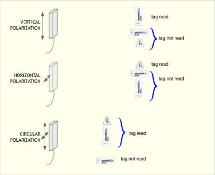
The best power transfer between antennas is obtained when their polarizations match. Thus the best read
range is obtained from e.g. a vertically polarized reader antenna transmitting to a vertically polarized tag
antenna. This is an excellent scheme to employ when the orientation of the tag during reading can be
controlled. However, if the orientation of the tag can vary, the tag could accidentally be perpendicular to
the polarization of the reader antenna – a horizontal tag with a vertically polarized signal in shown in the
diagram below – in which case very little power is received, and the tag will not be read. When the tag
orientation is unknown or uncontrollable, a circularly polarized reader antenna should be used. Vertical
tags, horizontal tags, and tags rotated to intermediate angles can then be read with equal facility. However,
this versatility is not without cost. A circularly polarized signal can be regarded as the combination of a
horizontal and vertical signal, each containing half of the transmitted power. A linearly polarized tag
antenna only receives its own polarization, and thus half the transmitted power, being of the wrong
polarization, is wasted. The read range of a circularly polarized antenna with a linearly polarized tag is
reduced from what could be obtained with a linearly polarized reader antenna, if the tag orientation is
known.
Copyright© 2006 by Hitachi America Ltd. Subject to change without notice. This information is provided “as is”, no
claims of fit for purposes intended, merchantability or other are made. All trademarks, service marks, trade names and
logos are used in good faith and remain the property of their rightful owners. page 35
Real antennas always transmit more effectively in some directions than others. The ratio of the power
density in the direction of highest power to the average power radiated in all directions is the maximum
directive gain, often simply referred to as the gain of the antenna. It is important to note that antennas are
passive devices and don’t actually add any power to the signal provided by the reader: gain in this context
refers to the increased power received by a device in the best direction relative to the average of all
directions. The recommended linear antenna for the HSS-MUR-300, the Maxrad MP2400XFPT, provides
about 8 dBi of gain on both transmit and receive. In principle, antenna gain could be increased to increase
read range. However, in most jurisdictions, the maximum gain employed in unlicensed operation is limited
by regulation. For example, in the United States, the FCC limits the effective isotropic radiated power
(EIRP, the product of the actual power and the antenna gain) to 4 watts. Substitution of another antenna for
the recommended antenna can only be performed when an antenna of similar or lower gain, and of the
same general type, is used. FCC regulations (title 47 part 15) require that antennas be approved for use
with specific radio communications devices, unless they are installed by a professional installer, and that in
all cases the combination of antenna and radio device must operate within regulatory constraints.
External antennas are generally connected to the reader using flexible coaxial cables and connectors. It is
important to select these cables and connectors appropriately for the application. If an antenna must be
mounted a long distance from the cable (more than 3 meters), a large-diameter low-loss cable, such as RG-
213 or RG214 should be used.
The electrical impedance presented by an antenna is a complex function of the frequency, the antenna
shape, and the near-antenna environment. Antennas are carefully designed so that the electrical impedance
of the antenna is well-matched to the impedance of the device to which they are connected. For example,
the HSS-MUR-300 reader will generally employ a cable with 50 ohm characteristic impedance to connect
the reader to the antenna. In order for the power from the reader to be effectively transferred to the
antenna, the antenna must have an electrical impedance close to 50 ohms, with little capacitance or
inductance, at the frequency of operation. As noted previously, conductive objects or some other materials
such as aqueous liquids placed close to an antenna will change its impedance and thus degrade its match to
the cable. For best read range, keep such obstructions away from the antenna in directions of maximum
directive gain.