Hitachi Communication Technologies America USA-41001-KE-E PCS Band GSM Amplifier User Manual User s Manual

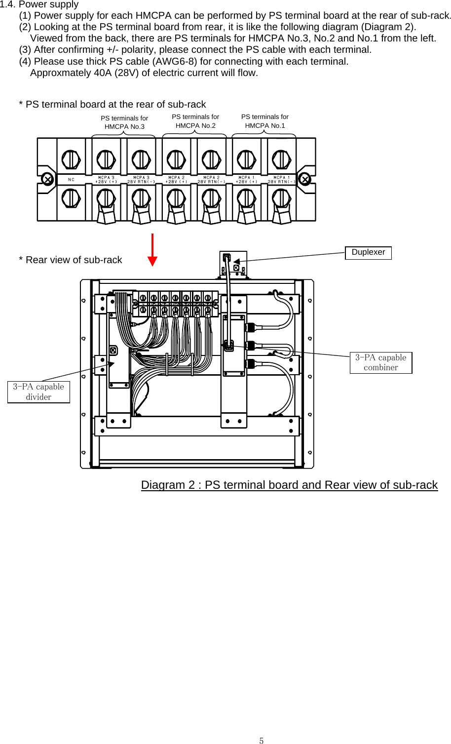
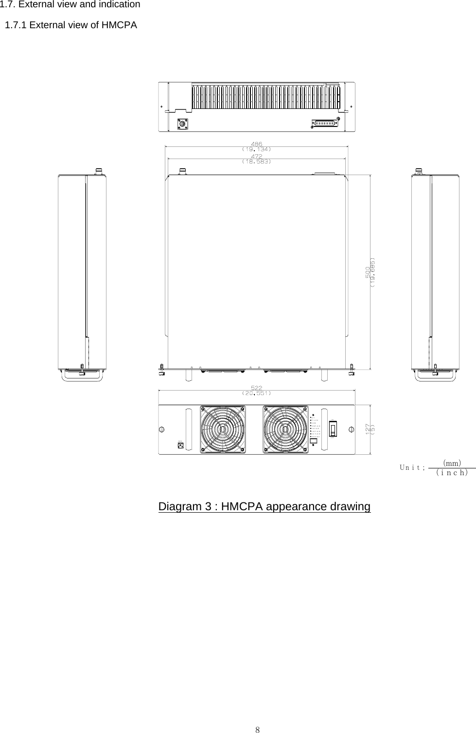
Hitachi Communication Technologies America, Inc PCS Band GSM Amplifier User s Manual

User manual

120-Watt Hitachi Multi-Carrier Power Amplifier (HMCPA)User's Manual (Quick Manual)June, 2004Hitachi Telecom (USA), Inc.Hitachi Kokusai Electric, Inc.1
1. Rack configulation (Operation)1.1. Configulation diagramThe configulation is shown in the following "Diagram 1".Diagram 1 : RACK-3HMCPA configulation1.2. Summary(1) One sub-rack contains three HMCPAs. Installation procedure is mentioned in section 3.(2) The cables for connecting a 3-PA capable combiner, a 3-PA capable divider, a duplexer and each unit have already    been connected.(3) The gain from 3-PA capable divider's input to duplexer's output is 50dB.(4) If you want to check the characteristic of 3-PA capable combiner's output, please remove the RF cable connecting    3-PA capable combiner with duplexer and then measure at the output of 3-PA capable combiner.    Maximum 330 watts can be achieved.(5) If you want to check the characteristic of 2-PA capable combiner's output, please replace the existing 3-PA capable    divider and 3-PA capable combiner with the attached 2-PA capable divider and 2-PA capable combiner respectively.    Maximum 220 watts can be achieved. Procedure to replace with 2-PA capable divider and 2-PA capable combiner    is mentioned in page 3 of this manual.1.3. HMCPA installation procedureHMCPA installation procedure is as follows and its explanatory diagram is shown in page 2.< Installation procedure ><1> Mount a HMCPA on Slider 1.<2> Insert the HMCPA into a sub-rack carefully. (Slide the HMCPA on Slider 2.)<3> The HMCPA will stop at the position in which the connector contacts.<4> Press the HMCPA in the sub-rack until the front panel of the HMCPA contacts with the sub-rack. (The connection of    the connector can be made.)  After that, please fix the HMCPA by using the fixing screws (2 screws) at the front panel.<5> Please make the same procedure written above against HMCPA No.1-No.3.< Note >(1) Please assign two persons or more to install a HMCPA. (Weight of a HMCPA : Approx. 22kg)(2) Do not insert a HMCPA with great force, otherwise it will damage the connector.(3) Fixing screws (2 screws) at the front panel must be screwed into the correponding holes at sub-rack.          3-PAcapableDividerMCPA No.3MCPA No.2MCPA No.1          3-PAcapableCombinerDUP+28V+28V RTN+28V RTN+28V RTN+28V +28V RTN +28V +28V RTN +28V +28V RTN+28V+28VRack OUTRack IN2
MCPA Installation diagram (3-PA combined)HMCPA Installation ProcedureHMCPA will stop at this positionOFFONACTPS ALMVS WRTEMPALMFAN ALMLOOP ALMGAI N ALMOV E R DR VOFFOFFONONACTACTPS ALMPS ALMVS WRVS WRTEMPALMTEMPALMFAN ALMFAN ALMLOOP ALMLOOP ALMGAI N AL MGAI N AL MOV E R DR VOV E R DR VMCPA No.1MCPA No.2MCPA No.3<1> <2><3><4><5>Press the HMCPA in the sub-rack.AttentionSlider Slider 3
 Replacement Procedure (2-PA capable combiner / divider)In case of 2-PA combining, please use MCPA No.2 and No.3.<6> Fix a 2-PA capable combiner with the attached screws (M4 : 2 pcs).<7> Fix a 2-PA capable divider with the attached screws (M4 : 2 pcs).<8> Connect two RF connectors with a 2-PA capable combiner.<9> Connect two connectors with a 2-PA capable divider.<10> Connect  the RF connector connecting a duplexer with 2-PA capable combiner.Note)   RF cable must be kept horizontal for more than   30 mm. (Donnot curve the cable at its root.)<1> Remove the RF connector connecting a duplexer with 3-PA capable combiner.<2> Remove three RF connectors from 3-PA capable combiner.<3> Remove three connectors from 3-PA capable divider.<4> Remove the screws (M3 : 4 pcs) for 3-PA capable combiner.<5> Remove the screws (M3 : 4 pcs) for 3-PA capable divider.<1><2><3><4><5>⑦⑥⑧⑨⑩<7> <9> <10> <6><8>4
1.4. Power supply(1) Power supply for each HMCPA can be performed by PS terminal board at the rear of sub-rack.(2) Looking at the PS terminal board from rear, it is like the following diagram (Diagram 2).    Viewed from the back, there are PS terminals for HMCPA No.3, No.2 and No.1 from the left.(3) After confirming +/- polarity, please connect the PS cable with each terminal.(4) Please use thick PS cable (AWG6-8) for connecting with each terminal.    Approxmately 40A (28V) of electric current will flow.* PS terminal board at the rear of sub-rack* Rear view of sub-rackDiagram 2 : PS terminal board and Rear view of sub-rackPS terminals for HMCPA No.3PS terminals for HMCPA No.2PS terminals for HMCPA No.13-PA capablecombinerDuplexer3-PA capabledivider5
1.5. HMCPA activation and RF test method(1) Supply power voltage (+28V) to the PS terminal board at the rear of sub-rack.(2) Turn ON each HMCPA by switching the Circuit breaker located at the right side of the front panel.    Please check that "ACT" LED is blinking.  In addition, please check that approx. 15A (on +28V) of idling current is flowing.(3) Input the 1945MHz-1975MHz signal from the input terminal ("RACK IN") located at the rear of sub-rack.(4) For 250W output at duplexer's output connector, approx. +4dBm (total power) should be input from the input terminal.(5) Since the gain of sub-rack has been set at aprox. 50dB, it is possible to perform 54dBm (250W) output at duplexer's    output connector.(6) Since the transmiting band width of the duplexer itself is from 1945MHz to 1975MHz, if you want to make a evaluation test    for the band width other than this, please remove the cable connecting a duplexer with 3-PA capable combiner and measure    at the output connector of 3-PA cable combiner.    When you remove the cable between a duplexer and a 3-PA capable combiner, please unscrew both sides of the connectors    at the same time.(7) Since the HMCPA submitted this time doesn't have DCDC converter, the voltage supplied to sub-rack will be used     as the power voltage of the FET inside HMCPA as it is.  Therefore, the efficiency and the distortion characteristic will    be affected according to the voltage supplied to sub-rack.6
1.6. Electrical performance  1.6.1 Environmental conditionThis sample's performance is subject to the following condition.   * Ambient temperature : -5 degrees C to +50 degrees C   * Relative humidity : 0% to 95%   * Storage temperature : -20 degrees C to +70 degrees C   * Storage humidity : 0% to 95%  1.6.2 Electrical performanceThe electrical performance of this sample is shown in the following "Table 1.6.2-1".Table 1.6.2-1 : Electrical performanceGSM EDGE RemarkGMSK 8PSK1930 to 1990MHz The transmitting band width of the duplexer equipped this time is from 1945 to 1975MHz, accordingly the frequency range at the output connector of the duplexer is from 1945 to 1975MHz. Usable in consecutive 30MHzPlease refer to "Note 1".Max 8 carriers Max 8 carriers Rack input to Duplexer output Linear gain within +/-0.5dBApplicable to the sample submitted this time.Operational (with DC/DC converter)Applicable to;  * 120W output by a HMCPA  * 330W output by 3-PA combining  * 220W output by 2-PA combiningApplicable to;  * 100W output by a HMCPA  * 250W output at duplexer output   connectorApplicable to;  * 120W output by a HMCPA  * 330W output by 3-PA combining  * 220W output by 2-PA combiningApplicable to;  * 100W output by a HMCPA  * 250W output at duplexer output   connectorThe level which is approx. -50dB attenuated from HMCPA module output level can be monitored.Note 1)Removing the RF cable between duplexer and 3-PA capable combiner enables 330W output at the output connector of 3-PA capable combiner.Besides, replacing the existing 3-PA capable divider and 3-PA capable combiner with the attached 2-PA capable divider and 2-PA capablecombiner respectively and connecting with HMCPA No.2 and No.3 enable 220W output at the output connector of 2-PA capable combiner.Attention)(1) Please donnot input the carriers other than 1945MHz-1975MHz, connecting to a duplexer.  Otherwise, though HMCPA amplifies it,     all the amplified power will be reflected at the duplexer and VSWR alarm will occur.  When you have a test by using the carriers     other than 1945-1975MHz, please remove the cable between a duplexer and a combiner in advance without fail.(2) Overinput is prohibited.    Plus 1dB from 120W output per HMCPA occurs Overinput alarm and shut down the HMCPA.  In case of initial configuration status    (250W using a duplexer), plus 1.5dB from specified input value (4dBm) occurs Overinput alarm and shut down the HMCPA.ItemSystem GainPass band FlatnessModulationFrequency RangeOperating Bandwidth Output PowerNumber of Carriers+24V to +30VApprox. 12.5%(Approx. 10.4%)Approx. 13.6%                         (GSM: 4 or EDGE: 2 carriers)(Approx. 11.3%)Approx. 12.5%(Approx. 10.4%)DC Input VoltageEfficiency of HMCPA system(consisting of Sub-rack and HMCPAs)Vd=24V(Vd=28V)Input / Output Return Loss Input Dynamic RangeIMDHarmonicsOut of Band Spurious-50dB +/- 1.0dB30MHz50dB +/- 1.0dB< +/- 0.5dB> 30dB250W<-65dBc<-50dBc<-60dBc+28VEfficiency of a HMCPA moduleVd=24V(Vd=28V)Monitor PortApprox. 10.4%(Approx. 8.6%)> 14dB7
1.7. External view and indication  1.7.1 External view of HMCPADiagram 3 : HMCPA appearance drawingPS ALMLOOP ALMGAI N ALMACTVSWRTEMP ALMFANALMOVE R DRV OFFONMONUnit;(mm)(inch)8
  1.7.2 IndicationThe indications on the front panel of HMCPA and the rear view of HMCPA are shown in the following "Diagram 4".Diagram 4 : The indications on the front panel of HMCPA and the rear view of HMCPARear viewPS ALMLOOP ALMGAI N AL MACTVSWRTEMPALMFAN ALMOVE R DR V OF FONMO NPS ALML OOP AL MGAI N AL MACTVSWRTEMPALMFAN ALMOV E R DR VFront view9
  1.7.3 Exlanation of indicated portionTable 1.7.3-1 : Indicated portionLED colorDescriptionGreenLED will blink when power source is supplied and no ALM occurs.RedLED will light up when the supply voltage for HMCPA is under +23V or over +30V.RedLED will light up when HMCPA output is OPEN or SHORT.RedLED will light up when the temperature rise inside HMCPA may damage the internal circuit. RedLED will light up when both cooling fans equipped inside HMCPA are damaged.RedLED will light up when the distortion compensation circuit doesn't work properly.RedLED will light up when the gain of HMCPA is unstable.Redgp ppower for HMCPA is exceeding the specific input value by 1.0dB or more. * ACT LED is normally blinking, but in case that the above-mentioned alarm happens, ACT LED will go out and   the corresponding ALM LED will light up.  In this case, HMCPA will automatically shut down.  1.7.4 Explanation of operated portionTable 1.7.4-1 : Operated portion  VSWRTEMP ALMIndication Name"ACT" LED"PS ALM" LEDACTPS ALMFAN ALMLOOP ALMGAIN ALMOVER DRV"VSWR ALM" LED"TEMP ALM" LED"FAN ALM" LED"LOOP ALM" LED"GAIN ALM" LED"OVER DRV" LEDOperated portion Name FunctionCIRCUIT BREAKERPower switchSwitch to turn ON and OFF.  "ON" side : Power ON  "OFF" side : Power OFFMON Monitor terminalThe signal with the level which is approxmately 50dB attenuated from the level at MCPA OUT (High-frequency output connector) will be output.  (SMA connector)D-SUB D-sub connectorD-SUB cable contains RF input connector and power source line.MCPA OUTHigh-frequency output connectorThis is a transmitting signal output terminal of HMCPA. (N connector)10
2. Individual HMCPA (Evaluation)This section is the procedure to evaluate a HMCPA module.Removing the RF cables at the rear of sub-rack and supplying the specified power source enable the performanceof single HMCPA to be confirmed.As to the procedure, please refer to the followings.2.1. HMCPA installationThis manual is referring to the case to measure MCPA No.1 located at the lowermost shelf.Please mount a HMCPA on the lowermost shelf by referring our previous operation manual (Document No. : BXLPA-A001).2.2. Connection of Power supply cable(1) Power supply for each HMCPA can be performed by PS terminal board at the rear of sub-rack.(2) Looking at the PS terminal board from rear, it is like the following diagram (Diagram 1).    Viewed from the back, there are PS terminals for HMCPA No.1, No.2 and No.3 from the right.(3) After confirming +/- polarity, please connect the PS cable with the rightmost terminal (HMCPA No.1).(4) Please use thick PS cable (AWG6-8) for connecting with this terminal.    Approxmately 40A (28V) of electric current will flow.Diagram 1 : PS terminal board at the rear of sub-rack2.3. Removal of RF cable(1) Duplexer, PS terminal board, 3-PA capable combiner, 3-PA capable divider and RF cables have been     already installed in a sub-rack. (Please refer to Diagram 2)(2) Please remove the connector of the input-side RF cable 1 (connecting HMCPA and 3-PA capable    divider) from a 3-PA capable divider.  The removed connector which is leading to a HMCPA will be    used as a input connector for HMCPA No.1.(3) In a similar way, please remove the connector of the output-side RF cable 1 (connecting HMCPA and    3-PA capable combiner) from a 3-PA capable combiner.  The removed connector which is leading to    a HMCPA will be used as a output connector for HMCPA No.1.Note) Please do not curve the cable at the root of output-side connector.PS terminals for HMCPA No.3 PS terminals for HMCPA No.2 PS terminals for HMCPA No.111
Diagram 2 : Rear view of sub-rack2.4. HMCPA activation and RF test method(1) Supply power voltage (+28V) to the PS terminal board at the rear of sub-rack.(2) Turn ON HMCPA No.1 by switching its Circuit breaker located at the right side of the front panel.    Please check that "ACT" LED is blinking.  In addition, please check that approx. 15A (on +28V) of    idling current is flowing.(3) Input your expecting 30MHz signal from the input-side connector of input-side RF cable 1 which is    referred in section 3.-(2) above.(4) For 102W output at HMCPA No.1, approx. -1.7dBm input signal should be input from the said    input-side connector.(5) For 120W output at HMCPA No.1, approx. -1.02dBm input signal should be input from the said    input-side connector.(6) Since the HMCPA submitted this time doesn't have DCDC converter, the voltage supplied to     sub-rack will be used as the power voltage of the FET inside HMCPA as it is.    Therefore, the efficiency and the distortion characteristic will be affected according to the voltage    supplied to sub-rack.3-PA capablecombinerDuplexerOutput-side RF cable 1(connecting HMCPA No.1 and 3-PA capable combiner)Input-side RF cable 1(connecting HMCPA No.1 and 3-PA capable divider)3-PA capabledi id12

Navigation menu