Hitachi Information and Telecommunication Systems EMG21 Gateway Wireless Router User Manual
Hitachi, Ltd., Information & Telecommunication Systems Company Gateway Wireless Router Users Manual
UserManual.wiki
>
Hitachi Information and Telecommunication Systems
>
EMG21 User Manual
Users Manual
Navigation menu
Upload a User Manual
Namespaces
Wiki Guide
HTML
PDF
Info
Views
User Manual
Discussion / Help
Navigation


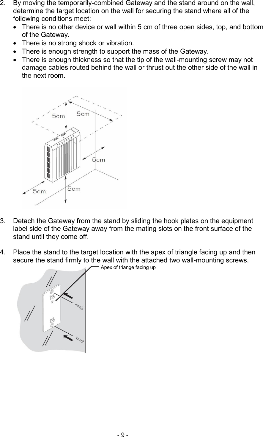
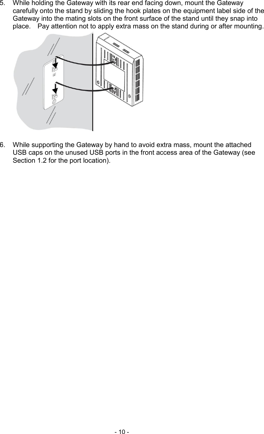
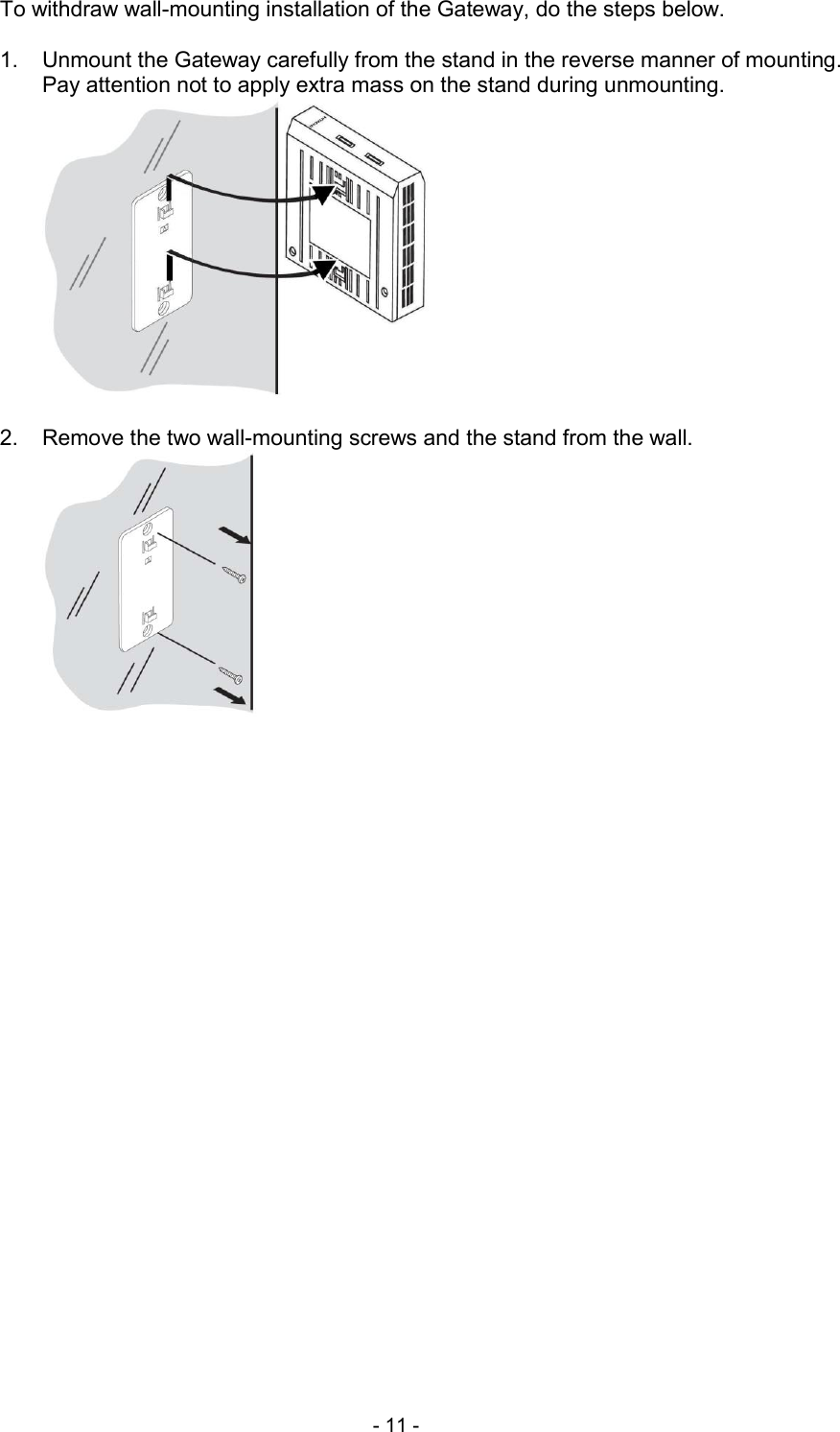
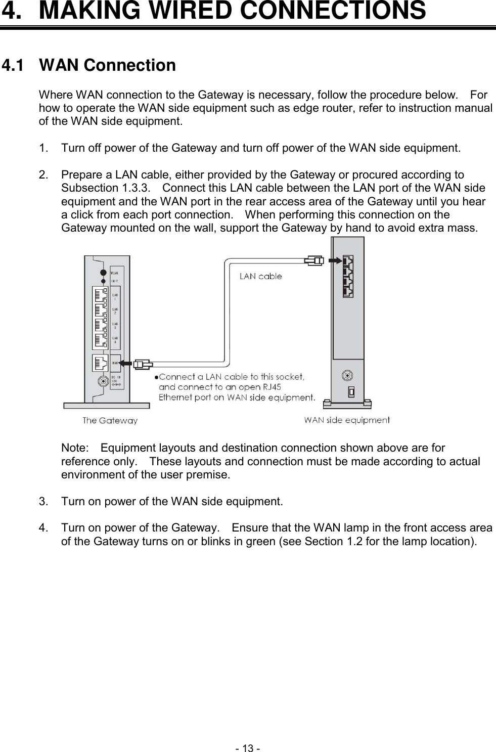
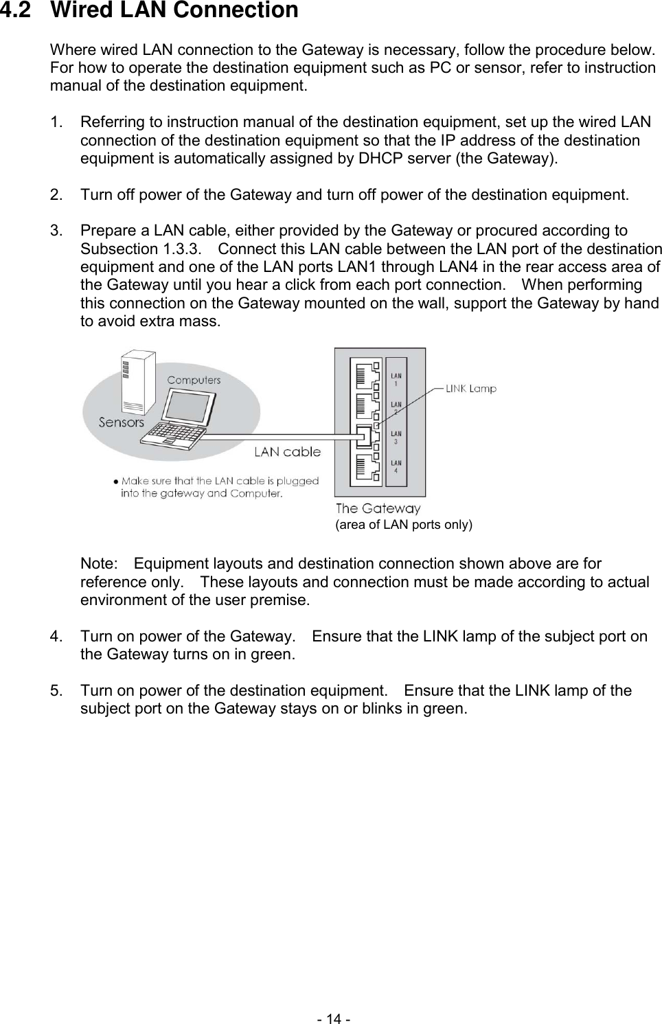

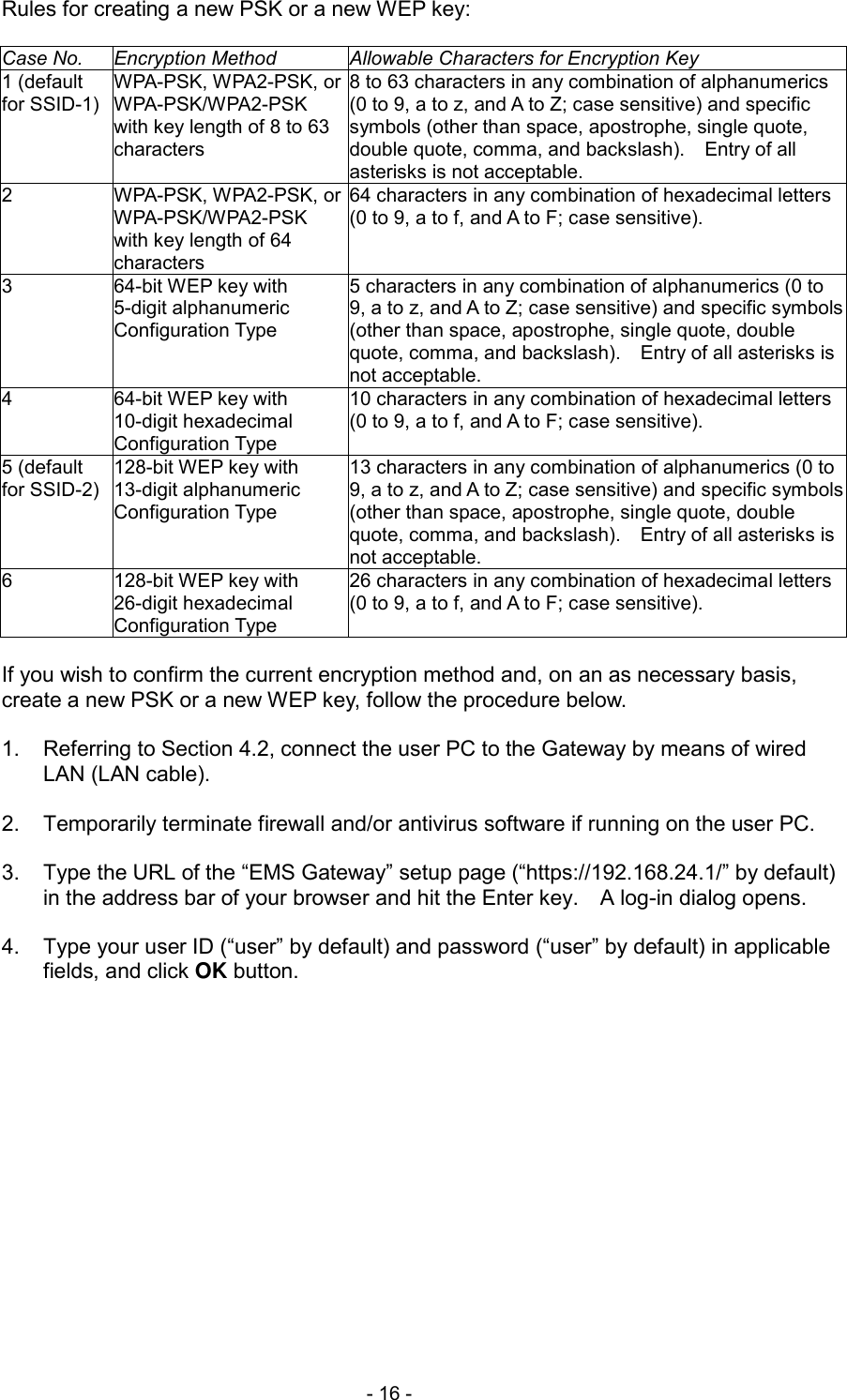
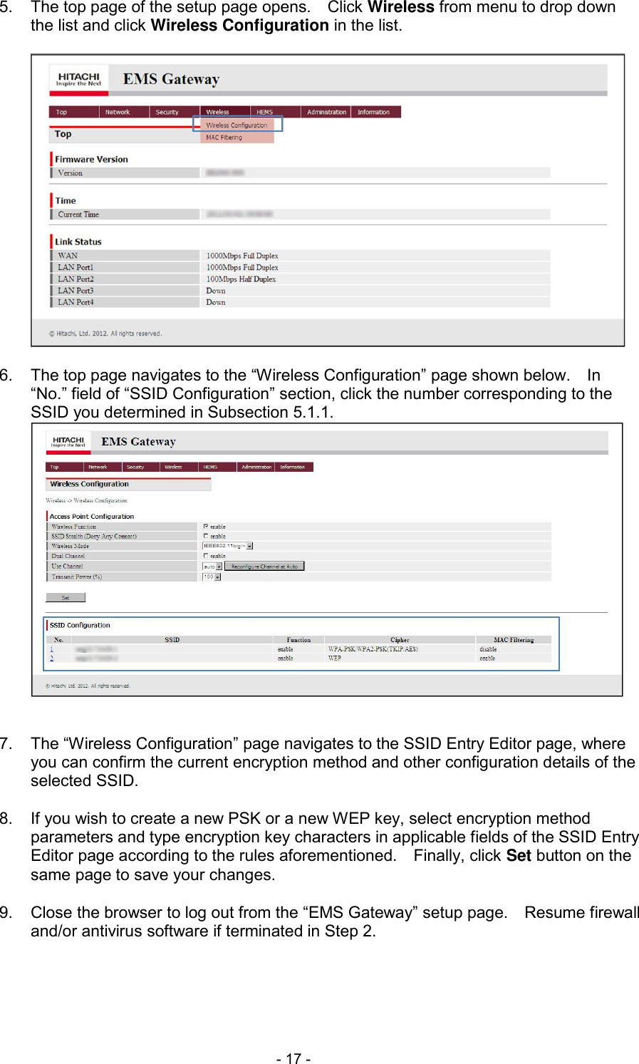


![- 38 - This product includes cryptographic software written by Eric Young (eay@cryptsoft.com). This product includes software written by Tim Hudson (tjh@cryptsoft.com). Original SSLeay License Copyright (C) 1995-1998 Eric Young (eay@cryptsoft.com). All rights reserved. This package is an SSL implementation written by Eric Young (eay@cryptsoft.com). The implementation was written so as to conform with Netscape's SSL. This library is free for commercial and non-commercial use as long as the following conditions are adhered to. The following conditions apply to all code found in this distribution, be it the RC4, RSA, lhash, DES, etc., code; not just the SSL code. The SSL documentation included with this distribution is covered by the same copyright terms except that the holder is Tim Hudson (tjh@cryptsoft.com). Copyright remains Eric Young's, and as such any Copyright notices in the code are not to be removed. If this package is used in a product, Eric Young should be given attribution as the author of the parts of the library used. This can be in the form of a textual message at program startup or in documentation (online or textual) provided with the package. Redistribution and use in source and binary forms, with or without modification, are permitted provided that the following conditions are met: 1. Redistributions of source code must retain the copyright notice, this list of conditions and the following disclaimer. 2. Redistributions in binary form must reproduce the above copyright notice, this list of conditions and the following disclaimer in the documentation and/or other materials provided with the distribution. 3. All advertising materials mentioning features or use of this software must display the following acknowledgement: "This product includes cryptographic software written by Eric Young (eay@cryptsoft.com)" The word 'cryptographic' can be left out if the routines from the library being used are not cryptographic related :-). 4. If you include any Windows specific code (or a derivative thereof) from the apps directory (application code) you must include an acknowledgement: "This product includes software written by Tim Hudson (tjh@cryptsoft.com)" THIS SOFTWARE IS PROVIDED BY ERIC YOUNG "AS IS" AND ANY EXPRESS OR IMPLIED WARRANTIES, INCLUDING, BUT NOT LIMITED TO, THE IMPLIED WARRANTIES OF MERCHANTABILITY AND FITNESS FOR A PARTICULAR PURPOSE ARE DISCLAIMED. IN NO EVENT SHALL THE AUTHOR OR CONTRIBUTORS BE LIABLE FOR ANY DIRECT, INDIRECT, INCIDENTAL, SPECIAL, EXEMPLARY, OR CONSEQUENTIAL DAMAGES (INCLUDING, BUT NOT LIMITED TO, PROCUREMENT OF SUBSTITUTE GOODS OR SERVICES; LOSS OF USE, DATA, OR PROFITS; OR BUSINESS INTERRUPTION) HOWEVER CAUSED AND ON ANY THEORY OF LIABILITY, WHETHER IN CONTRACT, STRICT LIABILITY, OR TORT (INCLUDING NEGLIGENCE OR OTHERWISE) ARISING IN ANY WAY OUT OF THE USE OF THIS SOFTWARE, EVEN IF ADVISED OF THE POSSIBILITY OF SUCH DAMAGE. The license and distribution terms for any publicly available version or derivative of this code cannot be changed. i.e. this code cannot simply be copied and put under another distribution license [including the GNU Public License]. ====================================================================](https://usermanual.wiki/Hitachi-Information-and-Telecommunication-Systems/EMG21/User-Guide-1837480-Page-53.png)