Hitachi Managed Services Business Division PCKCM50 Portable Biometric Reader User Manual Short Term Confidential

Hitachi, Ltd.,Information & Telecommunication Systems Company Portable Biometric Reader Short Term Confidential

Contents

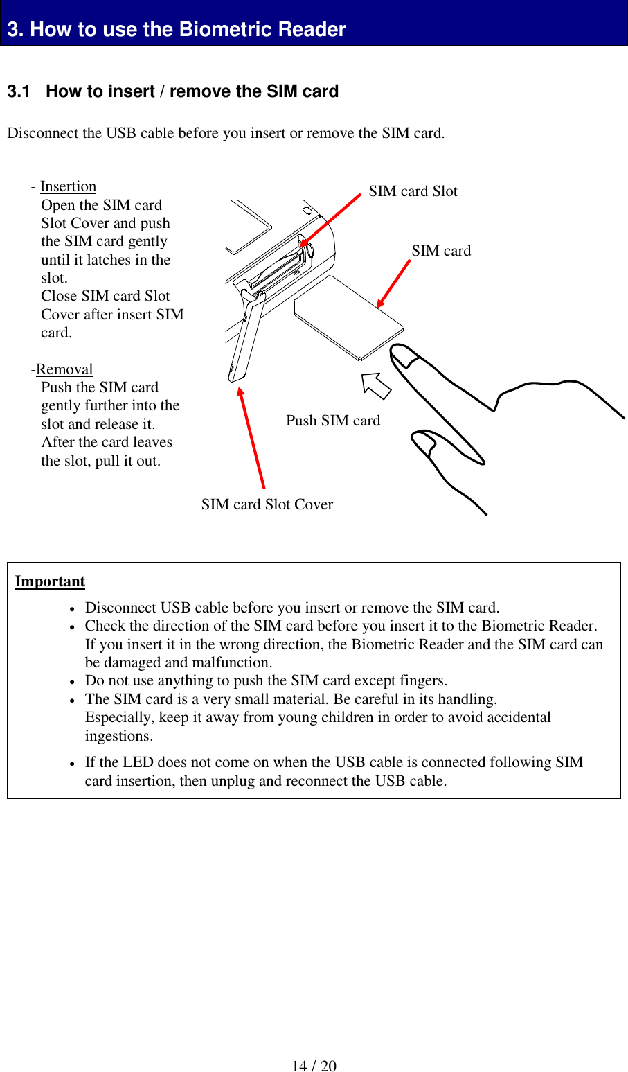
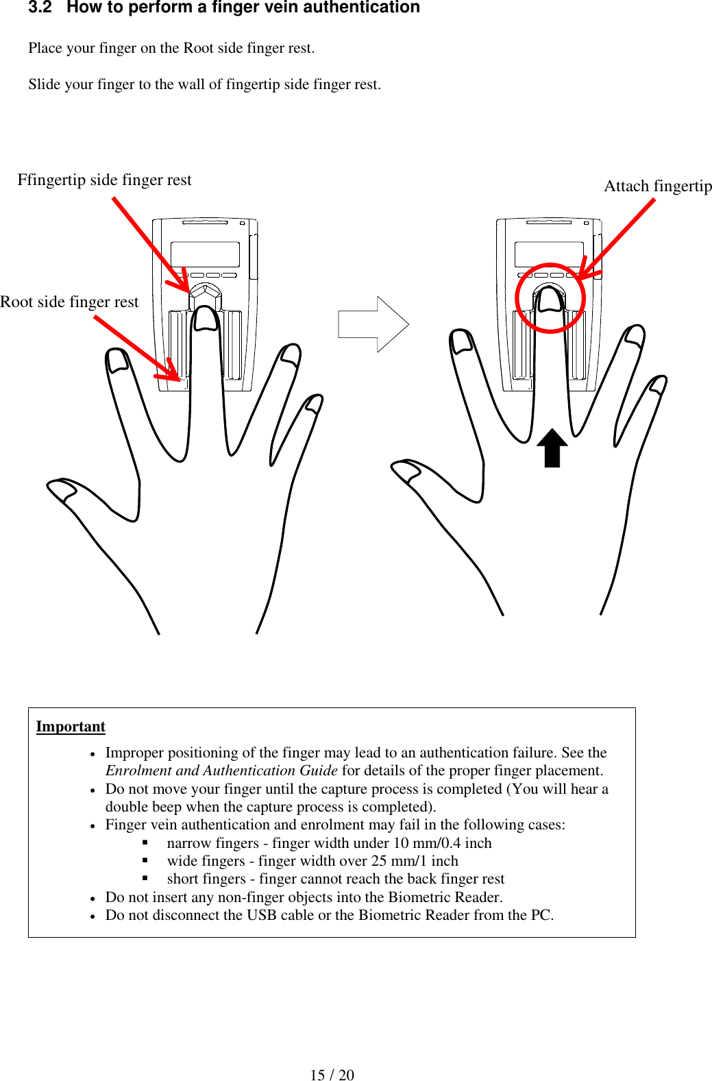
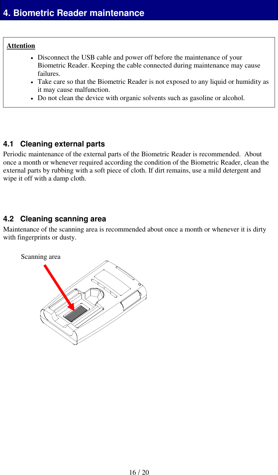
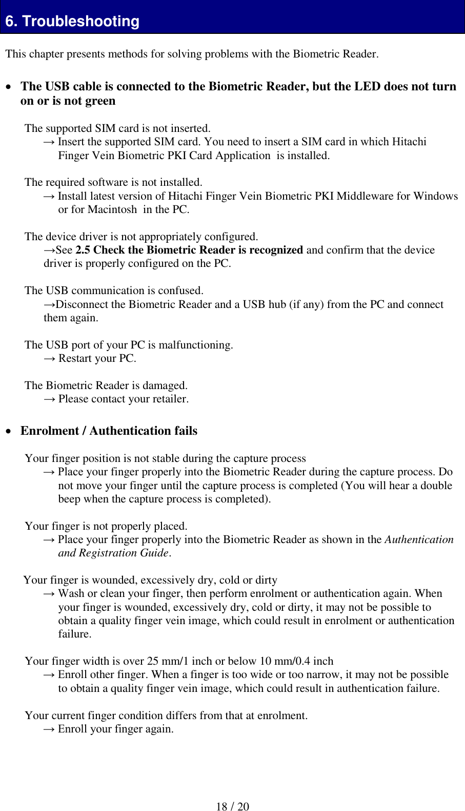
(Short-Term Confidential) User Manual

 1 / 20  Hitachi Biometric Reader  PC-KCM50 User Guide   Read all guidelines in this document carefully before using this product. This document should be kept for the future reference.  Important Notices  Quoting or partial / total reprinting of the contents of this document without license is prohibited.  The contents of this document are subject to change without notice.  In the case of any errors, inaccuracies or omissions in the contents of this document, please contact your distributor.  Hitachi, Ltd. permits the acquisition and use of the product according to the conditions stated in this document.  According to the statements contained in previous paragraphs, Hitachi, Ltd. will not assume any liability or obligation for damage of any kind arising from the use of this product. Consequently, do not use the product unless you fully understand its operation.   Product Reliability   The product you have purchased has been designed and manufactured for general office use. Avoid its use for applications that require extremely high reliability or in cases where lives or property may be at stake, for example the control of chemical plants, medical devices, urgent communications etc.  Hitachi, Ltd. assumes no liability for any such use and for any derived circumstances that may lead to accidents if used inappropriately.  Hitachi, Ltd. does not guarantee the correct functioning of this product if it is used simultaneously with other identification devices.   Regulations and Measures  ICES-003 Statements This Class B digital apparatus complies with Canadian ICES-003. Cet appareil numérique de la classe B est conforme à la norme NMB-003 du Canada.   Federal Communications Commission (FCC) Statement               This device complies with Part 15 of the FCC Rules. Operation is subject to the following two conditions:(1) this device may not cause harmful interference, and (2) this device must accept any interference received, including interference that may cause undesired operation. FCC CAUTION Changes or modifications not expressly approved by the party responsible for compliance could void the user’s authority to operate the equipment. The USB cable supplied in the package must be used for connection to the host computer in order to meet FCC emission limits.
 2 / 20  This transmitter must not be co-located or operated in conjunction with any other antenna or transmitter.  This equipment complies with FCC radiation exposure limits set forth for an uncontrolled environment and meets the FCC radio frequency (RF) Exposure Guidelines. This equipment has very low levels of RF energy that is deemed to comply without testing of specific absorption rate (SAR).   Note: This equipment has been tested and found to comply with the limits for a class B digital device, pursuant to Part 15 of the FCC Rules. These limits are designed to provide reasonable protection against harmful interference in a residential installation. This equipment generates, uses, and can radiate radio frequency energy and, if not installed and used in accordance with the instructions, may cause harmful interference to radio communications. There is no guarantee that interference will not occur in a particular installation. If this equipment does cause harmful interference to radio or television reception, which can be determined by turning the equipment off and on, the user is encouraged to try to correct the interference by one or more of the following measures:   Reorient or relocate the receiving antenna.   Increase the separation between the equipment and receiver.   Connect the equipment into an outlet on a circuit different from that to which the receiver is connected.  Consult the dealer or an experienced radio/TV technician for help.    Exports Regulations Before exporting the product, verify legal requirements in each country in addition to U.S. regulations for export control, and make all necessary arrangements accordingly. The above applies to attachments and software surrounding the device as well. Contact your distributor should you have any concerns.   Disposal  When discarding this product, follow all regional and local laws. Also consult regulations regarding the material of each component.   Hazardous substance table for China  有毒有害物质或者元素 部件名称 铅 水银 镉 六价铬 多溴联苯 多溴二苯醚 (Pb) (Hg) (Cd) (Cr(VI)) (PBB) (PBDE) 印刷线路板 × ○ ○ ○ ○ ○ 机箱 ○ ○ ○ ○ ○ ○ 连接线缆 ○ ○ ○ ○ ○ ○ 光学部件 ○ ○ ○ ○ ○ ○ USB 线缆 ○ ○ ○ ○ ○ ○ ○:表示该有毒有害物质在该部件所有均质材料中的含量均在 GB/T26572-2011 规定的限量要求以下. ×:表示该有毒有害物质至少在该部件的某一均质材料中的含量超出 GB/T26572-2011 规定的限量要求. 备注:以上部件中,部分含有有毒有害物质超过是由于目前行业技术水平所限,暂时无法实现替代或减量化.
 3 / 20     Notes Attention:    If the device is not properly used, device failure may occur. Important:  If the device is not properly used, certain functions may not respond properly.    Safety Guidance  Do not use this product near wet places such as humidifiers, washing machines, cooking places, washbasins, baths and the like. This may cause damage to the product.  Do not use damaged or badly bent USB cables. If the cable is damaged, this may cause interruptions or malfunction.   Do not dismantle or modify this device. It may lead to damage and malfunction.
 4 / 20 1tion 1. Introduction  Hitachi gratefully acknowledges your purchase of the Hitachi Portable Biometric Reader Unit (hereafter referred to as “Biometric Reader”). The objective of this document is to provide a basic understanding of how to handle and use the Biometric Reader.   1.1   Product characteristics  The Biometric Reader is a biometric authentication device that performs individual authentication by capturing finger vein patterns.    1.2   What’s in the box  Your Biometric Reader package includes:  Biometric Reader  ·········· 1 unit  USB Cable (1.0m/3.3ft)  ····· 1 piece  1.3   Biometric Reader components  Overhead view                    Back view          Scanning area (The area capturing the finger vein pattern) Indicator LED Ir LED SIM card slot Charge LED Button (4pcs) Display USB connector (Micro-B Type) Power Switch Strap hole
 5 / 20 1.4   LED color and Biometric Reader status  The indicator LED shows the status of the Biometric Reader.  Depending on its color and blinking state, please take an appropriate action. Note that Hitachi Finger Vein Biometric PKI Middleware (hereafter called the Middleware) for Windows (C-N1719-12) or for Macintosh (C-N1719-15) needs to be installed in the PC.   Note: On some PCs the LED doesn’t extinguish when the PC enters SLEEP or POWER OFF modes.   LED status Biometric Reader status Action Off Biometric Reader is not connected to the PC or Biometric Reader is not recognized by the Middleware. Connect the Biometric Reader to the PC. Install the Middleware. If the Middleware is already installed, disconnect the Biometric Reader and a USB hub (if any) from the PC and connect them again. Orange Biometric Reader is connected to the PC and is recognized by the Middleware. (SIM card is not inserted or recognized.) Insert a supported SIM card to the Biometric Reader. Orange blink Biometric Reader is connected to the PC and SIM card being is accessed. Wait until the LED status becomes Green.  Do not disconnect the Biometric Reader or remove the SIM card. If the Middleware is already installed, disconnect the Biometric Reader and a USB hub (if any) from the PC and connect them again. Blue Biometric Reader is connected to the PC and SIM card is recognized. Biometric Reader is to ready for use. - Blue blink (Slow) Biometric Reader is connected to the PC and is waiting to put the finger. Place your finger on the scanning area of the Biometric Reader. Blue blink (Fast) Biometric Reader is capturing finger vein. Place your finger until authentication is finished. Red Biometric Reader is connected to the PC and finger vein authentication failed. Retry finger vein authentication. Red blink Biometric Reader is connected to the PC and a device error occurred. Disconnect the Biometric Reader and a USB hub (if any) from the PC and connect them again.
 6 / 20 1.5 Display and Button  - Display  Reader Unit has a Display and four Push Buttons.          *1 Stop using and remove USB cable and power off. icon Function meaning  Connection On: Reader Unit is connected to Host Off: Reader is disconnect  Bluetooth On: Reader Unit is Bluetooth mode Off: Reader Unit is USB mode  Silent mode On: Buzzer of Reader Unit is Off  Caution On: Internal Error occur *1  Page Indicate Page remaining   remaining forward   remaining forward  and backward   remaining backward   Page Number Current Page number / Total page number  USB power On: USB bus power is supplied. Off: USB bus power is not supplied.  Battery Remaining Capacity    Full capacity    2/3    1/3    Low Battery (flush)    Error *1  Icon area Message area
 7 / 20   - Button  Reader Unit has four buttons.                      Button Function OK Push this button if the display content is OK. CANCEL Push this button if you want to cancel the process.  Push this button if you want to go backward page.  Push this button if you want to go forward page. Cancel button OK button Backward page button Forward page button
 8 / 20 1.6 Battery  Reader Unit has a 750mAh Lithium Ion battery. The battery is charged when USB cable is connected and USB bus power is supplied.  Reader Unit has one Charge LED and indicate charge status.    Important  The battery charger controls it so that charge current isn’t over USB bus power specification.  Therefore charge time become longer when Reader Unit is power on than it is power off.  Battery capacity at the display may not be updated immediately. In that case, it will be updated after waiting a moment.   For extending battery cycle life time, charge battery in environment more than 10 degree C if possible.   If you plan to store the Reader Unit for longer than six months, charge it to 2/3 every six months that remains in storage.     1.7 Rating Label                2. Installation of the Biometric Reader LED status Reader Unit status Remark Off Don’t charge or Discharge  Orange Charging  Orange blink Battery error Remove USB cable and stop using Reader Unit. Lot Number (6 digit) Manufacturing Number (7 digit) MJC26A 0000001
 9 / 20 2. Installation of the Biometric Reader 2.1   Place the Biometric Reader  Install the Biometric Reader on a horizontal and stable place. Ensure no light through a window or from lamps can enter the scanning area of the Biometric Reader.   It is recommended that you use the Biometric Reader in the 300-1000 lx luminance range, which is equivalent to the brightness suitable for reading a newspaper.  Important  Do not use the Biometric Reader in places where the Biometric Reader is exposed to strong light such as outdoors, near windows or near a light source, which may lead to an authentication failure.     2.2   Power On  Slide power switch (left side of the unit) to power on.          USB mode Power OFF Bluetooth mode With USB cable connection (powered by USB) - Power On - Connected by USB - Power Off - Power On - Connected by Bluetooth Without USB cable connection (powered by internal battery) - Power Off - Power Off - Power On - Connected by Bluetooth   Important  Reader Unit can’t power on by USB mode without USB bus power.  Reader Unit may hold some heat due to the use of infra-red rays inside, but this will not cause malfunctions.  Do not connect more than two Reader Units simultaneously to one PC. If multiple Reader Units are connected, they will not work properly.  After connecting the Reader Unit to your PC, wait for at least 5 seconds before performing any operation.     USB mode Bluetooth mode Power Switch Power OFF
 10 / 20 2.3   Connect the USB cable  Connect the USB Micro-B plug of the USB cable to the USB Micro-B connector of the Biometric Reader.             Connect the plug A of the USB cable to the USB port of your PC.   Attention  Connect the USB plug and the USB connector securely. Hold the plug end when connecting or disconnecting the USB cable to prevent the connectors from damage.  Important  When connecting the USB cable via a USB hub, check the supply current. The Biometric Reader may malfunction with insufficient power supply.  Do not use a USB 1.1 hub for a USB 2.0 PC port, which may cause the Biometric Reader to malfunction.  Biometric Reader may generate some heat due to the use of infra-red light inside, but this will not cause any malfunctions.  Do not connect more than one Biometric Reader simultaneously to one PC. If multiple Biometric Readers are connected, they will not work properly.  After connecting the Biometric Reader to your PC, wait for at least 5 seconds before performing any operation. In some PCs it may take more than 5 seconds until the Biometric Reader becomes ready for use.   Reader Unit USB Micro-B connector USB Micro-B plug USB cable
 11 / 20 2.4   Connect Bluetooth  Reader Unit has a Bluetooth SMART (Bluetooth Low Energy) interface. Slide power switch to Bluetooth mode, Reader Unit power up and connect Bluetooth.                               Important  First connection of Bluetooth, pairing is necessary.   This Unit’s wireless range of Bluetooth is 10m (Class 2).  Following things may interfere with wireless range and throughput of Bluetooth. - Other wireless device (Bluetooth, Wi-Fi, codeless phone etc.) - Microwave oven - steel furniture - Concreate wall etc.  Don’t use Bluetooth mode at a location where transmission of radio waves is prohibited.  This Unit is compatible with Bluetooth Smart (Bluetooth Low Energy), but it does not guarantee a connection with all of Bluetooth Smart Ready.  The battery can be charged at Bluetooth mode when USB cable is connected and USB bus power is supplied.
 12 / 20 2.5   Check the Biometric Reader is recognized  After connecting the Biometric Reader to your PC, check that the Biometric Reader is recognized correctly by the PC. Note that Windows and Macintosh uses the Smart card readers device driver to access the Biometric Reader, so you do not need to install a specific device driver for the Biometric Reader.  Confirm that the Biometric Reader is displayed in the Device Manager (Windows) or System Information (Macintosh).
 13 / 20 2.6   Removing the Biometric Reader  Use following procedure to safely remove the Biometric Reader at USB mode.  1. Click the Safely Remove Hardware and Eject Media icon in the notification area, at the far right of the taskbar.  Note: To display the Safely Remove Hardware and Eject Media icon,            click Show hidden icons icon (the arrow at the left side of the notification area).   2. Click the name of the Biometric Reader in the list.  You are prompted that it is safe to remove the Reader.  3. Remove the Reader.
 14 / 20 3. How to use the Biometric Reader 3. How to use the Biometric Reader  3.1   How to insert / remove the SIM card  Disconnect the USB cable before you insert or remove the SIM card.                        Important  Disconnect USB cable before you insert or remove the SIM card.  Check the direction of the SIM card before you insert it to the Biometric Reader. If you insert it in the wrong direction, the Biometric Reader and the SIM card can be damaged and malfunction.  Do not use anything to push the SIM card except fingers.  The SIM card is a very small material. Be careful in its handling. Especially, keep it away from young children in order to avoid accidental ingestions.  If the LED does not come on when the USB cable is connected following SIM card insertion, then unplug and reconnect the USB cable.             - Insertion Open the SIM card Slot Cover and push the SIM card gently until it latches in the slot. Close SIM card Slot Cover after insert SIM card.  -Removal Push the SIM card gently further into the slot and release it. After the card leaves the slot, pull it out.     Push SIM card SIM card SIM card Slot SIM card Slot Cover
 15 / 20 3.2   How to perform a finger vein authentication  Place your finger on the Root side finger rest.  Slide your finger to the wall of fingertip side finger rest.                                   Important  Improper positioning of the finger may lead to an authentication failure. See the Enrolment and Authentication Guide for details of the proper finger placement.  Do not move your finger until the capture process is completed (You will hear a double beep when the capture process is completed).  Finger vein authentication and enrolment may fail in the following cases:  narrow fingers - finger width under 10 mm/0.4 inch  wide fingers - finger width over 25 mm/1 inch  short fingers - finger cannot reach the back finger rest  Do not insert any non-finger objects into the Biometric Reader.  Do not disconnect the USB cable or the Biometric Reader from the PC.  Ffingertip side finger rest Attach fingertip Root side finger rest
 16 / 20 Biometric Reader maintenance 4. Biometric Reader maintenance   Attention  Disconnect the USB cable and power off before the maintenance of your Biometric Reader. Keeping the cable connected during maintenance may cause failures.    Take care so that the Biometric Reader is not exposed to any liquid or humidity as it may cause malfunction.  Do not clean the device with organic solvents such as gasoline or alcohol.     4.1   Cleaning external parts Periodic maintenance of the external parts of the Biometric Reader is recommended.  About once a month or whenever required according the condition of the Biometric Reader, clean the external parts by rubbing with a soft piece of cloth. If dirt remains, use a mild detergent and wipe it off with a damp cloth.     4.2   Cleaning scanning area Maintenance of the scanning area is recommended about once a month or whenever it is dirty with fingerprints or dusty.                           Scanning area
 18 / 20 6. Troubleshooting  This chapter presents methods for solving problems with the Biometric Reader.    The USB cable is connected to the Biometric Reader, but the LED does not turn on or is not green  The supported SIM card is not inserted. → Insert the supported SIM card. You need to insert a SIM card in which Hitachi Finger Vein Biometric PKI Card Application  is installed.  The required software is not installed. → Install latest version of Hitachi Finger Vein Biometric PKI Middleware for Windows or for Macintosh  in the PC.  The device driver is not appropriately configured. →See 2.5 Check the Biometric Reader is recognized and confirm that the device driver is properly configured on the PC.   The USB communication is confused. →Disconnect the Biometric Reader and a USB hub (if any) from the PC and connect them again.  The USB port of your PC is malfunctioning. → Restart your PC.  The Biometric Reader is damaged. → Please contact your retailer.   Enrolment / Authentication fails  Your finger position is not stable during the capture process → Place your finger properly into the Biometric Reader during the capture process. Do not move your finger until the capture process is completed (You will hear a double beep when the capture process is completed).  Your finger is not properly placed. → Place your finger properly into the Biometric Reader as shown in the Authentication and Registration Guide.  Your finger is wounded, excessively dry, cold or dirty  → Wash or clean your finger, then perform enrolment or authentication again. When your finger is wounded, excessively dry, cold or dirty, it may not be possible to obtain a quality finger vein image, which could result in enrolment or authentication failure.   Your finger width is over 25 mm/1 inch or below 10 mm/0.4 inch → Enroll other finger. When a finger is too wide or too narrow, it may not be possible to obtain a quality finger vein image, which could result in authentication failure.  Your current finger condition differs from that at enrolment.  → Enroll your finger again.
 19 / 20 An internal error occurred in the Biometric Reader. →Disconnect the Biometric Reader and a USB hub (if any) from the PC and connect them again.    Enrolment / Authentication does not start  The Biometric Reader is not ready to start the enrolment or authentication process.  → When the Biometric Reader is connected to the PC and SIM card is inserted properly, its LED light is green. However, when connecting the Biometric Reader or inserting the SIM card, you need to wait for at least 5 seconds until the LED status changes from blank or blinking orange to green, before performing an operation. In some PCs it may take more than 5 seconds until the LED status changes to green.
 20 / 20  Copyright   © Hitachi, Ltd. 2016. All rights reserved.  The software and the manual can be used and managed under the responsibility of the administrator registered in the relevant document of Biometric Reader.  Without the express consent of Hitachi, Ltd., the following is prohibited:    1. Reproduction, photocopying or transference of this user's guide contents, either     partially or in its entirety, as well as the transfer of the registration information      contained in the Unit memory.  2. Translation of this user's guide to any computer languages or any other language.   The use of any electronic, mechanical, magnetic, optic or similar procedures for performing the above actions laid down in points 1 and 2 is also prohibited.   All other logos, product names, brand names and company names mentioned herein are either trademarks or registered trademarks of their respective owners.   Hitachi Biometric Reader  PC-KCM50 User Guide 1st Edition February 2016  Reproduction is forbidden without consent.  © Hitachi, Ltd. 2016. All rights reserved.

Navigation menu