Hitachi Omron Terminal Solutions HA-1234 Bluetooth Adapter User Manual HA 1234 User s Manual rev2
Hitachi-Omron Terminal Solutions,Corp. Bluetooth Adapter HA 1234 User s Manual rev2
Users Manual

1/10
User’s Manual for Bluetooth Profile Unit
Model: HA-1234
[Rev. R01]
[October 12, 2004]
Hitachi-Omron Terminal Solutions,Corp.
Read this manual thoroughly and keep it
• Be sure to read safety descriptions in the manual and understand them before using this product.
• Keep the manual at hand for your quick reference.

2/10
Introduction
Thank you for purchasing the Bluetooth Profile Unit (HA-1234).
The unit enables wireless data communication using Bluetooth and has the following features:
• Bluetooth Serial Port Profile (SPP) is built in.
• Bluetooth Class 2 transmission output power is supported, enabling wireless communication in the
distance range of 10m with clear view.
• Unique command interface enables command control and data communication using a single
serial port.
• Bluetooth-standard function for encrypted communication is supported.
• Bluetooth-standard low power state function (Sniff mode) is supported.
Notices
● No part of this manual may be reproduced without permission.
● Contents of this manual may be subject to change without prior notice.
● Applications described in this manual show typical ones for use with our products. This manual never
guarantees implementation of industrial property right and other rights or grants license. And also, any
problems, related to industrial property right and others, resulting from using the product, arise with a third
party, please note that we take no responsibility for them.
● Please note that we take no responsibility for effect led by the operation result regardless of the preceding
clause.
● The unit is available for use in limited areas. If you are thinking of using it overseas, contact us.
● If you build the unit into another device and then use it in Japan, it is recommended that words such as
“Contains wireless equipment with Technical Regulations Conformity Certification Stipulated in the Radio
law ” be labeled on the relevant device.
● If you build the unit into another device and then use it in North America, be sure to label the words
“Contains FCC ID: SOE-HA-1234” on the relevant device.
Trademark notice
Bluetooth is a trademark for Bluetooth SIG. Inc., USA.
All Rights Reserved, Copyright(C) 2004 Hitachi-Omron Terminal Solutions,Corp

3/10
Important
Warning: abnormal heat, smoke and unusual sound/smell
If something abnormal occurs during use, stop use the unit, turn the power off and disconnect the power cable
immediately. Failure to do so may result in electric shock or fire.
Caution: Interference
Installing the unit adjacent to other electronics equipment may have harmful effects on each other. If equipment
including TV and radio are existed near the unit, noises may be produced. In such case, do as described below.
• Separate the unit from equipment including TV and radio as far as possible.
• Reorient these equipment antennas.
Precautions for Handling
● If the unit is used with systems, which require a high level of reliability and safety in their functions and
performance, such as operation equipment (e.g. aircraft, train, vehicle), disaster/crime-prevention equipment
and safety devices produced by various manufactures, please take the whole safety design into consideration by
implementing fail-safe design or redundant design in order to maintain the reliability and safety of the whole of
these systems/equipment.
● The unit is not intended to use with equipment, which requires extremely high level of reliability and safety,
such as aerospace equipment, mainline-communication equipment, nuclear energy control equipment or life-
support medical equipment. Never use the unit with these equipment.
● The unit is a communication device using radio waves in conformance with Bluetooth specifications. When
the unit is used in places where radio waves are apt to spread out (e.g. outdoors where no obstacles exist) or
where radio waves are not be transmitted smoothly indoors separated by walls, the transmittable distance may
be changed, depending on the wave conditions. Please note that even during normal communication they may
be interrupted, depending on the wave conditions
● The unit uses radio waves. Thus, there is possibility of getting wiretapped by third parties. If you require the
communication to be concealed, use concealment process such as encryption function of the unit.
● Please note that we take no responsibility for pure economic loss resulting from losing a chance of
communication or others due to wrong operation, malfunction or external factors including power failure.
● Installing the unit near microwave, TV, radio or speaker may produce harmful effects of noises and others.
● We take no responsibility for damages resulting from cases such as where the unit is used by deviating from
its use conditions or precautions described in this manual.
Precautions for Mounting / Installation
● The wireless unit complies with Radio Law. Never disassemble or modify it.
Precautions for Operation
● Be sure to use the unit with rated voltage, temperature and humidity. Failure to do so may causes
malfunction of the unit, and also its performance will not be guaranteed.

4/10
Tested to Comply With FCC Standards, FOR HOME OR OFFICE USE
Federal Communication Commission Interference Statement
This equipment has been tested and found to comply with the limits for a Class B digital device, pursuant to
Part 15 of the FCC Rules. These limits are designed to provide reasonable protection against harmful
interference in a residential installation. This equipment generates, uses and can radiate radio frequency energy
and, if not installed and used in accordance with the instructions, may cause harmful interference to radio
communications. However, there is no guarantee that interference will not occur in a particular installation. If
this equipment does cause harmful interference to radio or television reception, which can be determined by
turning the equipment off and on, the user is encouraged to try to correct the interference by one of the
following measures:
- Reorient or relocate the receiving antenna.
- Increase the separation between the equipment and receiver.
- Connect the equipment into an outlet on a circuit different from that to which the receiver is connected.
- Consult the dealer or an experienced radio/TV technician for help.
FCC Caution: To assure continued compliance, (example - use only shielded interface cables when
connecting to computer or peripheral devices) any changes or modifications not expressly approved by the
party responsible for compliance could void the user's authority to operate this equipment.
This device complies with Part 15 of the FCC Rules. Operation is subject to the following two conditions: (1)
This device may not cause harmful interference, and (2) this device must accept any interference received,
including interference that may cause undesired operation.
IMPORTANT NOTE:
FCC Radiation Exposure Statement:
This equipment complies with FCC RF radiation exposure limits set forth for an uncontrolled environment. To
maintain compliance with FCC RF exposure compliance requirements, please avoid direct contact to the
transmitting antenna during transmitting.

5/10
IMPORTANT NOTE:
Industry
Canada
/
//
/
Radio
Equipment
Certification number for radio field will be given by Industry Canada if the product meets the demand of IC
technical specification.
Operation of this device is subjected to the following two conditions :
(1) this device may not cause interference, and (2) this device must accept any interference, including
nterference that may cause undesired operation of the device.
The installer of this radio equipment must be ensured that the antenna does not emit RF field limit, which is
defined by Health.
Canada for general public. For more details, see Safety Code 6, from Health Canada's website www.hc-
sc.gc.ca/rpb
6/10
Scope
This manual describes how to operate HA-1234/Bluetooth Profile Unit (BPU).
2. Unit Specifications
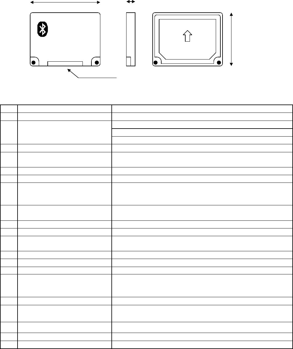
2.1 Part Names
2.2 Unit Specifications
No.
Item Specifications
1 Bluetooth Specification Bluetooth Specification v1.2
2 Profile Support Generic Access Profile
Service Discovery Application Profile
Serial Port Profile
3 BD Address IEEE std802 48bit LAN MAC Address
4 Bluetooth Device Name Desired One Settable
(Default: “Bluetooth Profile Unit” ASCII)
5 Bluetooth Device Class Desired One Settable (Default: “000000” HEX)
6 Link Key 7 Key Storable (Store in ROM.)
7 Discoverability Mode “Non-discoverable Mode”, “General discoverable Mode”
Supported
“Limited discoverable Mode” Unsupported
8 Pairing Mode Supported
Selectable between “Non-pairable Mode”/“Pairable Mode”
9 Bluetooth Pass Key (PIN) Desired One Settable (Default: “1111” ASCII)
10
Security Mode Selectable between “Security Mode 1” and “Security Mode 3”
11
Inquiry “General Inquiry” Supported
“Limited Inquiry” Unsupported
12
Bluetooth Name Discovery Supported
13
Encryption Supported
14
Low Power State “Sniff Mode” Supported
15
RS-232C Communication
Specifications (PC – BPU)
(Note 1)
Baudrate: 9600bps (Note2), Data Length: 8bits
Stop-bit length: 1bit, Parity: None
Flow Control: RTS/CTS Flow
16
Bluetooth Transmission Output Class 2
17
Bluetooth Communication
Distance
Aprox. 10m
18
Power Source DC : +3.3 –0.1/+0.2 V
19
Dimensions (39.5) x (30) x (5.4)mm
20
Weight Approx. 8g
(Note 1): The baudrate, data bit length, stop bit length and parity are variable. The values described in the table
are default ones.
(Note 2): The transmission rate is not effective speed.
Note: If the unit is built into other equipment, labeling
may be required on the relevant equipment.
15…………1
Label
I/f Connector
39.5±0.5
5.4±0.3
30±0.5

7/10
(2)Power Specifications
No.
Item Specifications
1 Supply Voltage DC: +3.3 –0.1/+0.2 V
2 Current Consumption (TYP) 80 - 100mA
3 Protective Function non
(3) DC Characteristics of Signal
No.
Mode symbol
min max unit Remarks
1 Input HIGH level V
IH
2.3
VCC+0.2
V VCC=3.3V
2 Input LOW level V
IL
0
VCCx0.15
V VCC=3.3V
3 Output HIGH level V
OH
1.8
V VCC=3.3V,I
OH
=-2mA
4 Output LOW level V
OL
0.65
V VCC=3.3V,I
OL
=2mA
5 Supply current Icc
120
mA
(4) Connector Pin Specifications
[Connector 1: Connector for Cable Connection (SM15B-SRSS-G-TB/Manufucturer:JST)]
No.
Signal Name
I/O Remarks
1
DCD O UART_SIGNAL
2
RXD O UART_SIGNAL
3
TxD I UART_SIGNAL
4
DTR I UART_SIGNAL
5
GND -
6
DSR O UART_SIGNAL
7
RTS I UART_SIGNAL
8
CTS O UART_SIGNAL
9
NC - Unconnected (Reserved) – Never connect anything.
10
VCC - +3.3 –0.1/+0.2V
11
NC - Unconnected (Reserved) – Never connect anything.
12
NC - Unconnected (Reserved) – Never connect anything.
13
GND -
14
LED1 O Status LED Signal
15
LED2 O Status LED Signal
(5) Environment Specifications
Item Environment Conditions
Operable: Temperature / Humidity
-20°C - +60°C / 20% - 80% (No Condensation)
Storage: Temperature / Humidity
-30°C - +75°C / 20% - 80% (No Condensation)
2.3 LED Lighting Specifications
BPU LED
Status
Status Red Green
0
X
H/W Initial Setting, H/W Checking
F/W Start-UP Process
1
X X
Waiting for F/W Initialization
2
X or Note
On Standby
3
Waiting for INQUIRY Completion
4
Waiting for REMOTENAME Completion
5
Waiting for Automatic Connection
6
X or Note
On Standby (Security Mode 1)
7
X or Note
On Standby (Security Mode 3)
8
X
Waiting for Connection Completion
9
X or Note
Connecting (Active Mode)
X X
Connecting (Sniff Mode)
A
X X
Waiting for Disconnection
B
X
Malfunction
C
X
Hardware Failure
: ON, : Blinking
(every 0.25sec)
, : Blinking
(every 0.5sec)
, : Blinking
(ON: every 0.25sec, OFF: every 0.75sec.)
: Blinking
(ON: every 0.75sec, OFF: every 0.25sec.),
:Blinking (every 1sec), X: OFF
Note: Red/Green LED comes on at the same time in Command Mode (DTR: OFF). (The color of the LED looks
orange.)
8/10
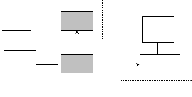
2.4 Connection Pattern
Devices, which the BPU is expected to communicate with, include the BPU connected to a serial device and
Bluetooth dongle device connected to a cellphone.
The BPU supports Point to Point connection and Multi-Point (Piconet) connection.
Serial
Printer
BPU
(Slave)
RS-232C
Connecting
Bluetooth
Bluetooth
Mobile Adapter
(Slave)
Remote Device Remote Device
PC
Cellphone
BPU
(Master)
RS-232C
2.5 Operation Mode
The BPU has two modes, “Command Mode” and “Communication Mode”, which are selected by DTR signal
input from PC.
(1) Command Mode
The mode accepts various kinds of setting and control for Bluetooth.
The mode enables connection to a remote device.
DTR signal at PC: OFF (signal level “0”) makes the BPU enter the mode.
(2) Communication Mode
The mode enables serial connection by Bluetooth, and also data transmission to/receive from a remote device.
DTR signal at PC: ON (signal level “1”) makes the BPU enter the mode.
[ Example ]
9/10
3. Functions
3.1 Command Mode Functions
The mode is used with DTR signals from PC: OFF. All data transmitted from PC under the condition are
interpreted as a command.
The BPU responds to a command and may give multiple responses to a single command.
No.
Item Command Description
1 Inquiry INQUIRY Makes inquiry and gets peripheral device information.
2 Get Remote Device Name REMOTENAME
Gets Bluetooth device name of a remote device.
3 Set Local Device LOCALDEVICE
Sets and gets Bluetooth device name and others of BPU.
4 Set Bluetooth Pass Key PASSKEY Sets and gets Bluetooth pass key for use in Authentication.
5 Set Bonding Information BOND Sets and gets bonding information for use in Authentication.
6 Connect CONNECT Connects to a remote device.
7 Wait for Connection WAIT Waits for connection from a remote device.
8 Disconnect DISCONNECT Disconnects from a remote device.
9 Set Communication SETBAUDRATE
Sets PC-BPU communication.
10 Check Version VERSION Indicates BPU firmware version.
11 Set Echo ECHO Sets whether response subsequent to completed
connection to Bluetooth is given or not.
12 Automatic Connection AUTO Sets automatic connection to a remote device.
13 Encryption ENCRYPTION Sets encrypted communication.
14 Local Status LOCALSTATUS
Gets PC-BPU signal status and BPU status.
15 Remote Status REMOTESTATUS
Gets signal/connection status of a remote device.
16 Set Park Mode PARK Sets low power consumption PARK Mode.
17 Get Error Information ERROR Gets error information occurred in BPU.
18 Reset RESET Resets BPU firmware.
19 Clear Command Buffer EOT (0x04) Clears command buffer in BPU.
20 Set Expanded Function EXFUNC Sets expanded functions.
21 Set Connection Time-out
TIMEOUT Sets time-out period for CONNECT command.
Table 1: Command List
PC BPU
Command
(After completing the process)
Response
Starting to process
DTR OFF
10/10
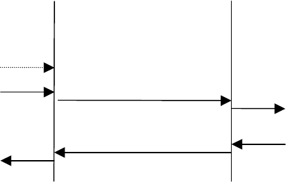
3.2 Communication Mode Function
DTR signal form PC: ON makes the BPU enter Communication Mode.
All data transmitted from PC in the mode are interpreted as transmit data to a remote device. And also, all data
the BPU receives from a remote device are transmitted to PC.
Data transmitted to the BPU, prior to connection to a remote device, with DTR ON are not sent to the remote
device as the data are cleared at the time of the connection.
PC BPU
Transmit Data
Remote Device
DTR ON
Receive Data
(Through)
(Connect to Remote Device)
(Clear Transmit/Receive
Buffer Clear)
Transmit Data
Receive Data