Hitachi Omron Terminal Solutions HA-1234 Bluetooth Adapter User Manual HA 1234 User s Manual rev2
Hitachi-Omron Terminal Solutions,Corp. Bluetooth Adapter HA 1234 User s Manual rev2
UserManual.wiki
>
Hitachi Omron Terminal Solutions
>
HA 1234 User Manual
Users Manual
Navigation menu
Upload a User Manual
Namespaces
Wiki Guide
HTML
PDF
Info
Views
User Manual
Discussion / Help
Navigation
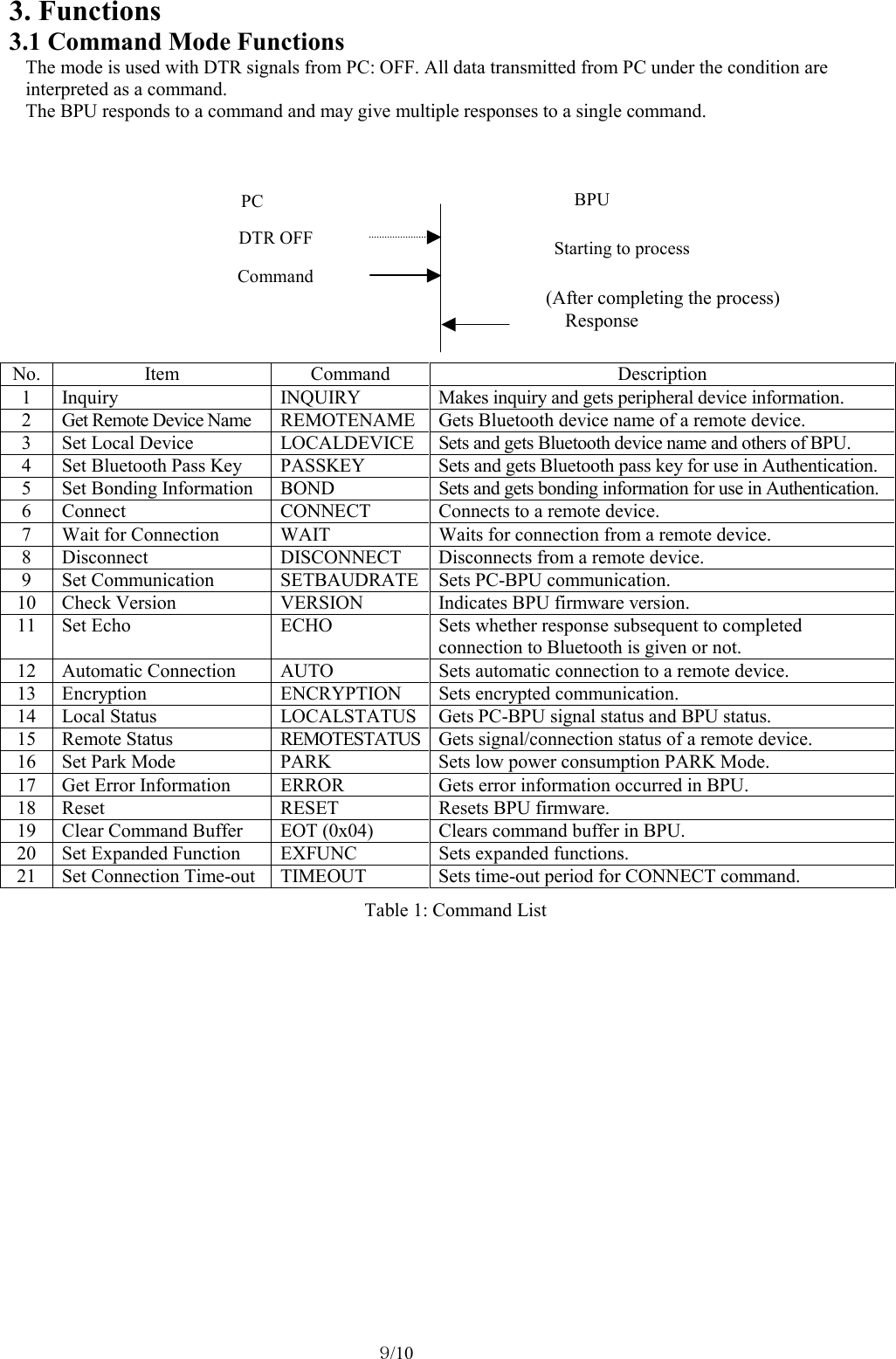
![1/10 User’s Manual for Bluetooth Profile Unit Model: HA-1234 [Rev. R01] [October 12, 2004] Hitachi-Omron Terminal Solutions,Corp. Read this manual thoroughly and keep it • Be sure to read safety descriptions in the manual and understand them before using this product. • Keep the manual at hand for your quick reference.](https://usermanual.wiki/Hitachi-Omron-Terminal-Solutions/HA-1234/User-Guide-512238-Page-1.png)
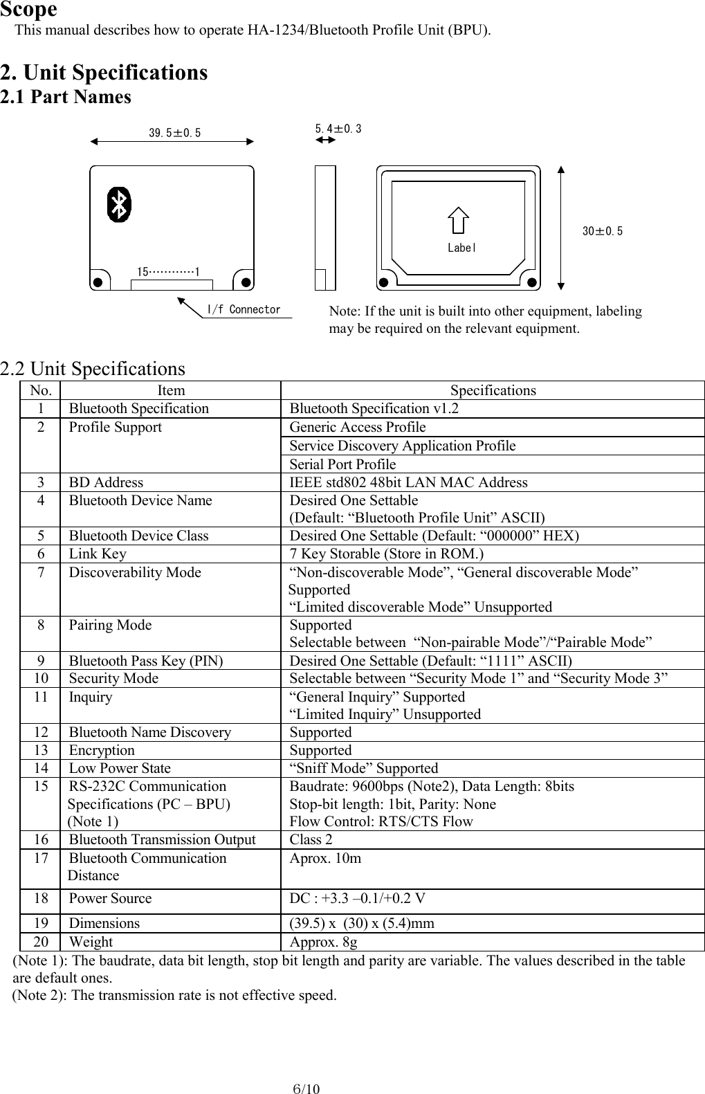
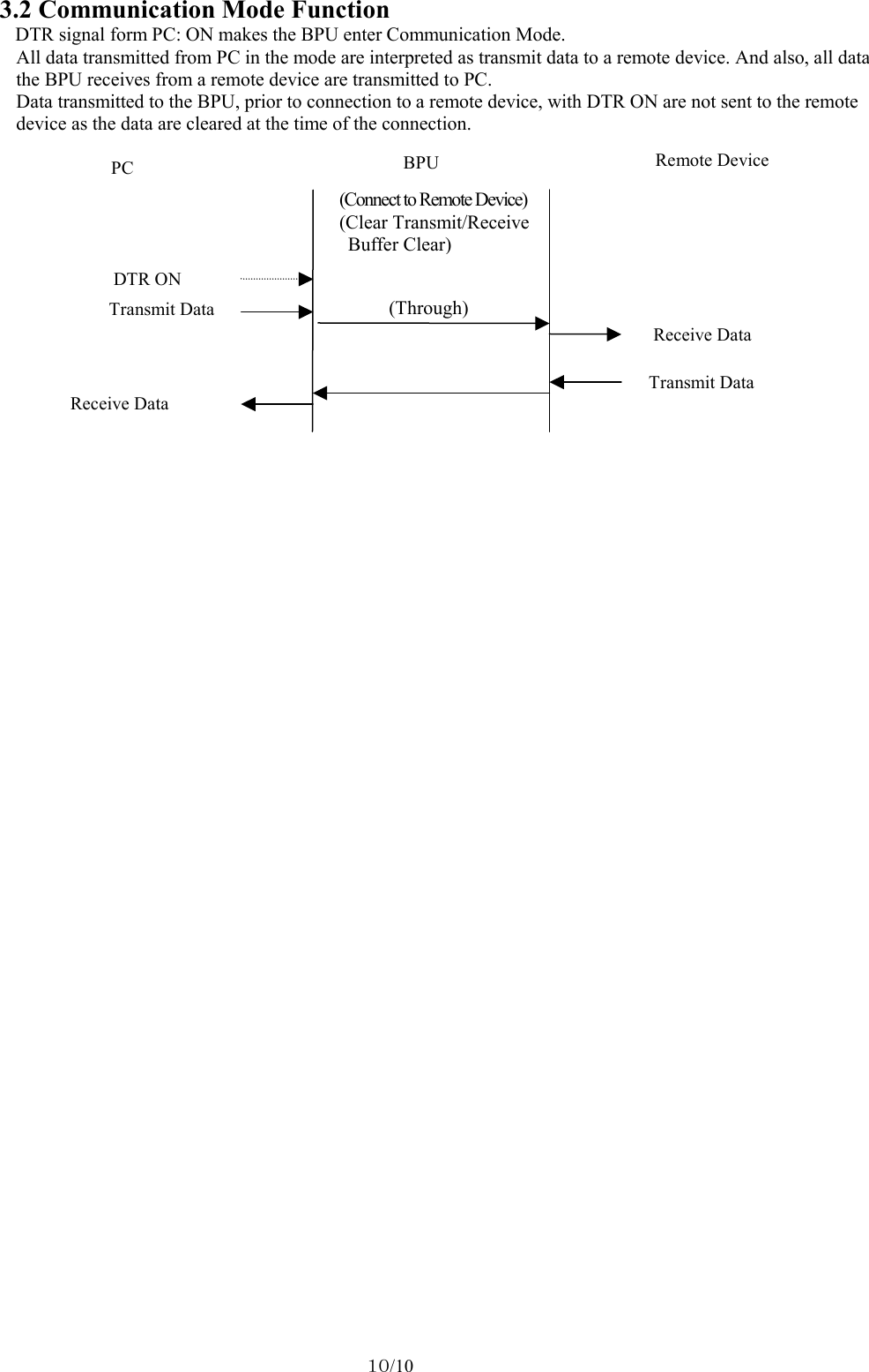
![7/10 (2)Power Specifications No. Item Specifications 1 Supply Voltage DC: +3.3 –0.1/+0.2 V 2 Current Consumption (TYP) 80 - 100mA 3 Protective Function non (3) DC Characteristics of Signal No. Mode symbol min max unit Remarks 1 Input HIGH level VIH 2.3 VCC+0.2 V VCC=3.3V 2 Input LOW level VIL 0 VCCx0.15 V VCC=3.3V 3 Output HIGH level VOH 1.8 V VCC=3.3V,IOH=-2mA 4 Output LOW level VOL 0.65 V VCC=3.3V,IOL=2mA 5 Supply current Icc 120 mA (4) Connector Pin Specifications [Connector 1: Connector for Cable Connection (SM15B-SRSS-G-TB/Manufucturer:JST)] No. Signal Name I/O Remarks 1 DCD O UART_SIGNAL 2 RXD O UART_SIGNAL 3 TxD I UART_SIGNAL 4 DTR I UART_SIGNAL 5 GND - 6 DSR O UART_SIGNAL 7 RTS I UART_SIGNAL 8 CTS O UART_SIGNAL 9 NC - Unconnected (Reserved) – Never connect anything. 10 VCC - +3.3 –0.1/+0.2V 11 NC - Unconnected (Reserved) – Never connect anything. 12 NC - Unconnected (Reserved) – Never connect anything. 13 GND - 14 LED1 O Status LED Signal 15 LED2 O Status LED Signal (5) Environment Specifications Item Environment Conditions Operable: Temperature / Humidity -20°C - +60°C / 20% - 80% (No Condensation) Storage: Temperature / Humidity -30°C - +75°C / 20% - 80% (No Condensation) 2.3 LED Lighting Specifications BPU LED Status Status Red Green 0 X H/W Initial Setting, H/W Checking F/W Start-UP Process 1 X X Waiting for F/W Initialization 2 X or Note On Standby 3 Waiting for INQUIRY Completion 4 Waiting for REMOTENAME Completion 5 Waiting for Automatic Connection 6 X or Note On Standby (Security Mode 1) 7 X or Note On Standby (Security Mode 3) 8 X Waiting for Connection Completion 9 X or Note Connecting (Active Mode) X X Connecting (Sniff Mode) A X X Waiting for Disconnection B X Malfunction C X Hardware Failure : ON, : Blinking (every 0.25sec), : Blinking (every 0.5sec), : Blinking (ON: every 0.25sec, OFF: every 0.75sec.) : Blinking (ON: every 0.75sec, OFF: every 0.25sec.), :Blinking (every 1sec), X: OFF Note: Red/Green LED comes on at the same time in Command Mode (DTR: OFF). (The color of the LED looks orange.)](https://usermanual.wiki/Hitachi-Omron-Terminal-Solutions/HA-1234/User-Guide-512238-Page-7.png)
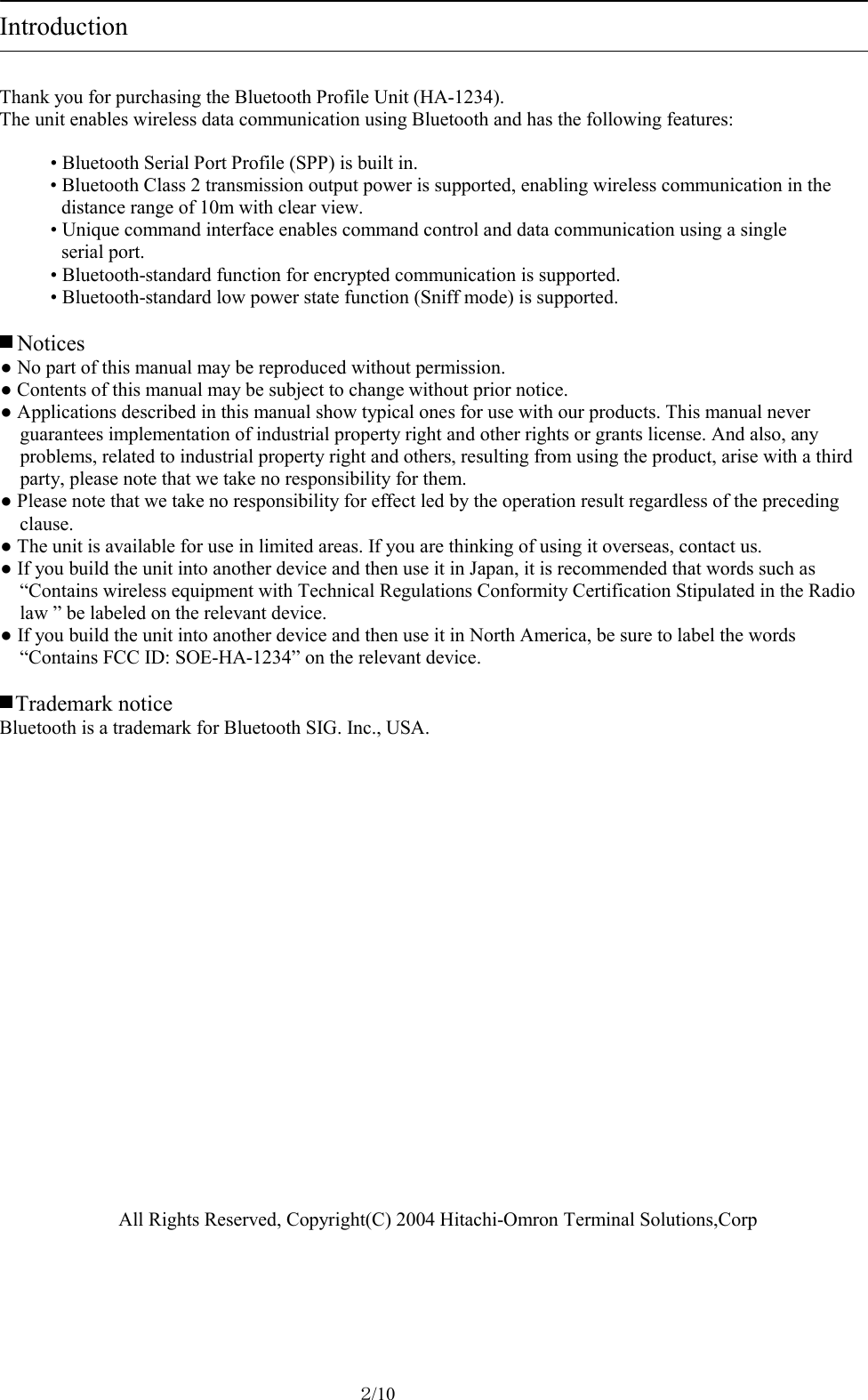
![8/10 2.4 Connection Pattern Devices, which the BPU is expected to communicate with, include the BPU connected to a serial device and Bluetooth dongle device connected to a cellphone. The BPU supports Point to Point connection and Multi-Point (Piconet) connection. Serial Printer BPU (Slave) RS-232C Connecting Bluetooth Bluetooth Mobile Adapter (Slave) Remote Device Remote Device PC Cellphone BPU (Master) RS-232C 2.5 Operation Mode The BPU has two modes, “Command Mode” and “Communication Mode”, which are selected by DTR signal input from PC. (1) Command Mode The mode accepts various kinds of setting and control for Bluetooth. The mode enables connection to a remote device. DTR signal at PC: OFF (signal level “0”) makes the BPU enter the mode. (2) Communication Mode The mode enables serial connection by Bluetooth, and also data transmission to/receive from a remote device. DTR signal at PC: ON (signal level “1”) makes the BPU enter the mode. [ Example ]](https://usermanual.wiki/Hitachi-Omron-Terminal-Solutions/HA-1234/User-Guide-512238-Page-8.png)