Hitachi L2002 Users Manual L200 Series Inverter Instruction
L2002 to the manual 01e20bc0-e116-2bb4-e974-fd8f5ca0035b
2015-01-24
: Hitachi Hitachi-L2002-Users-Manual-313561 hitachi-l2002-users-manual-313561 hitachi pdf
Open the PDF directly: View PDF ![]() .
.
Page Count: 304 [warning: Documents this large are best viewed by clicking the View PDF Link!]
- Cover
- Safety Messages
- Definitions and Symbols
- Hazardous High Voltage
- General Precautions - Read These First!
- Index to Warnings and Cautions in This Manual
- Cautions and Warnings for Orientation and Mounting Procedures
- Wiring - Warnings for Electrical Practices and Wire Specifications
- Wiring - Cautions for Electrical Practices
- Powerup Test Caution Messages
- Warnings for Configuring Drive Parameters
- Cautions for Configuring Drive Parameters
- Warnings for Operations and Monitoring
- Cautions for Operations and Monitoring
- Warnings and Cautions for Troubleshooting and Maintenance
- General Warnings and Cautions
- UL® Cautions, Warnings, and Instructions
- Table of Contents
- Getting Started
- Inverter Mounting and Installation
- Orientation to Inverter Features
- Basic System Description
- Step-by-Step Basic Installation
- Choosing a Mounting Location
- Ensure Adequate Ventilation
- Keep Debris Out of Inverter Vents
- Check Inverter Dimensions
- Prepare for Wiring
- Determining Wire and Fuse Sizes
- Terminal Dimensions and Torque Specs
- Wire the Inverter Input to a Supply
- Wire the Inverter Output to Motor
- Logic Control Wiring
- Uncover the Inverter Vents
- Powerup Test
- Using the Front Panel Keypad
- Configuring Drive Parameters
- Choosing a Programming Device
- Using Keypad Devices
- “D” Group: Monitoring Functions
- “F” Group: Main Profile Parameters
- “A” Group: Standard Functions
- Control Source Settings
- Basic Parameter Settings
- Analog Input Settings
- Multi-speed and Jog Frequency Setting
- Torque Control Algorithms
- DC Braking Settings
- Frequency-related Functions
- PID Control
- Automatic Voltage Regulation (AVR) Function
- Second Acceleration and Deceleration Functions
- Accel/Decel
- Additional Analog Input Settings
- “B” Group: Fine Tuning Functions
- “C” Group: Intelligent Terminal Functions
- “H” Group: Motor Constants Functions
- “P” Group: Expansion Card Functions
- Operations and Monitoring
- Introduction
- Connecting to PLCs and Other Devices
- Control Logic Signal Specifications
- Intelligent Terminal Listing
- Using Intelligent Input Terminals
- Forward Run/Stop and Reverse Run/Stop Commands:
- Multi-Speed Select
- Jogging Command
- External Signal for DC Braking
- Set Second Motor and Special-Set Second Motor
- Two-stage Acceleration and Deceleration
- Free-run Stop
- External Trip
- Unattended Start Protection
- Software Lock
- Analog Input Current/Voltage Select
- Reset Inverter
- Thermistor Thermal Protection
- Three-wire Interface Operation
- PID ON/OFF and PID Clear
- Remote Control Up and Down Functions
- Force Operation from Digital Operator
- ADD Frequency Enable
- Force Terminal Mode
- Quick Start Enable
- Using Intelligent Output Terminals
- Sinking Outputs, Open Collector
- Sinking Outputs, Open Collector with External Relays
- Internal Relay Output
- Output Signal ON/OFF Delay Function
- Run Signal
- Frequency Arrival Signals
- Overload Advance Notice Signal
- Output Deviation for PID Control
- Alarm Signal
- Analog Input Disconnect Detect
- PID Second Stage Output
- Network Detection Signal
- Logic Output Function
- Option Card Detection Signal
- Analog Input Operation
- Analog Output Operation
- PID Loop Operation
- Configuring the Inverter for Multiple Motors
- Inverter System Accessories
- Troubleshooting and Maintenance
- Glossary and Bibliography
- ModBus Network Communications
- Drive Parameter Settings Tables
- CE-EMC Installation Guidelines
- Index
L200
2
Series Inverter
Instruction Manual
• Single-phase Input 200V Class
• Three-phase Input 200V Class
• Three-phase Input 400V Class
After reading this manual,
keep it handy for future reference.
Hitachi Industrial Equipment Systems Co., Ltd.
Manual Number: NB675X
Sept. 2006
Cover
L2002 Inverter i
Safety Messages
For the best results with the L2002 Series inverter, carefully read this manual and all of
the warning labels attached to the inverter before installing and operating it, and follow
the instructions exactly. Keep this manual handy for quick reference.
Definitions and Symbols
A safety instruction (message) includes a “Safety Alert Symbol” and a signal word or
phrase such as WARNING or CAUTION. Each signal word has the following meaning:
HIGH VOLTAGE: This symbol indicates high voltage. It calls your attention to items
or operations that could be dangerous to you and other persons operation this equipment.
Read the message and follow the instructions carefully.
WARNING: Indicates a potentially hazardous situation that, if not avoided, can result in
serious injury or death.
CAUTION: Indicates a potentially hazardous situation that, if not avoided, can result in
minor to moderate injury, or serious damage to the product. The situation described in
the CAUTION may, if not avoided, lead to serious results. Important safety measures
are described in CAUTION (as well as WARNING), so be sure to observe them.
1 Step 1: Indicates a step in a series of action steps required to accomplish a goal. The
number of the step will be contained in the step symbol.
NOTE: Notes indicate an area or subject of special merit, emphasizing either the
product’s capabilities or common errors in operation or maintenance.
TIP: Tips give a special instruction that can save time or provide other benefits while
installing or using the product. The tip calls attention to an idea that may not be obvious
to first-time users of the product.
Hazardous High Voltage
HIGH VOLTAGE: Motor control equipment and electronic controllers are connected to
hazardous line voltages. When servicing drives and electronic controllers, there may be
exposed components with housings or protrusions at or above line potential. Extreme
care should be taken to protect against shock.
Stand on an insulating pad and make it a habit to use only one hand when checking com-
ponents. Always work with another person in case an emergency occurs. Disconnect
power before checking controllers or performing maintenance. Be sure equipment is
properly grounded. Wear safety glasses whenever working on electronic controllers or
rotating machinery.
ii
General Precautions - Read These First!
WARNING: This equipment should be installed, adjusted, and serviced by qualified
electrical maintenance personnel familiar with the construction and operation of the
equipment and the hazards involved. Failure to observe this precaution could result in
bodily injury.
WARNING: The user is responsible for ensuring that all driven machinery, drive train
mechanism not supplied by Hitachi Industrial Equipment Systems Co., Ltd., and process
line material are capable of safe operation at an applied frequency of 150% of the
maximum selected frequency range to the AC motor. Failure to do so can result in
destruction of equipment and injury to personnel should a single-point failure occur.
WARNING: For equipment protection, install a ground leakage type breaker with a fast
response circuit capable of handling large currents. The ground fault protection circuit is
not designed to protect against personal injury.
WARNING: HAZARD OF ELECTRICAL SHOCK. DISCONNECT INCOMING
POWER BEFORE WORKING ON THIS CONTROL.
WARNING: Wait at least five (5) minutes after turning OFF the input power supply
before performing maintenance or an inspection. Otherwise, there is the danger of
electric shock.
CAUTION: These instructions should be read and clearly understood before working
on L2002 series equipment.
CAUTION: Proper grounds, disconnecting devices and other safety devices and their
location are the responsibility of the user and are not provided by Hitachi Industrial
Equipment Systems Co., Ltd.
CAUTION: Be sure to connect a motor thermal disconnect switch or overload device to
the L2002 series controller to assure that the inverter will shut down in the event of an
overload or an overheated motor.
HIGH VOLTAGE: Dangerous voltage exists until power light is OFF. Wait at least five
(5) minutes after input power is disconnected before performing maintenance.
WARNING: This equipment has high leakage current and must be permanently (fixed)
hard-wired to earth ground via two independent cables.
L2002 Inverter iii
WARNING: Rotating shafts and above-ground electrical potentials can be hazardous.
Therefore, it is strongly recommended that all electrical work conform to the National
Electrical Codes and local regulations. Installation, alignment and maintenance should
be performed only by qualified personnel.
Factory-recommended test procedures included in the instruction manual should be
followed. Always disconnect electrical power before working on the unit.
CAUTION:
a) Class I motor must be connected to earth ground via low resistive path (< 0.1Ω)
b) Any motor used must be of a suitable rating.
c) Motors may have hazardous moving parts. In this event suitable protection must
be provided.
CAUTION: Alarm connection may contain hazardous live voltage even when inverter is
disconnected. When removing the front cover for maintenance or inspection, confirm
that incoming power for alarm connection is completely disconnected.
CAUTION: Hazardous (main) terminals for any interconnection (motor, contact
breaker, filter, etc.) must be inaccessible in the final installation.
CAUTION: This equipment should be installed in IP54 or equivalent (see EN60529)
enclosure. The end application must be in accordance with BS EN60204-1. Refer to the
section “Choosing a Mounting Location” on page 2–9. The diagram dimensions are to
be suitably amended for your application.
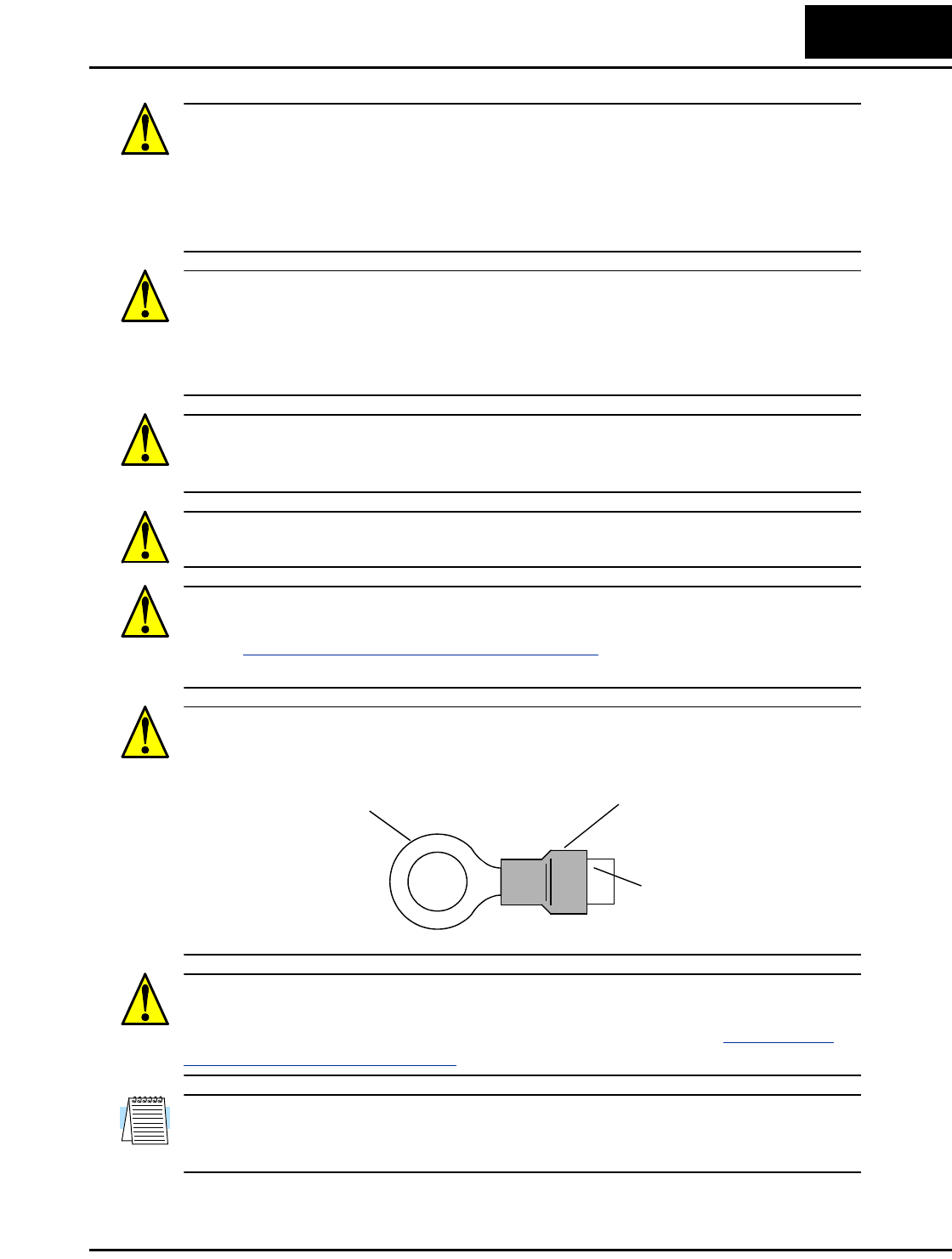
CAUTION: Connection to field wiring terminals must be reliably fixed having two
independent means of mechanical support. Use a termination with cable support (figure
below), or strain relief, cable clamp, etc.
CAUTION: A double-pole disconnection device must be fitted to the incoming main
power supply close to the inverter. Additionally, a protection device meeting IEC947-1/
IEC947-3 must be fitted at this point (protection device data shown in “Determining
Wire and Fuse Sizes” on page 2–17).
NOTE: The above instructions, together with any other requirements highlighted in this
manual, must be followed for continued LVD (European Low Voltage Directive)
compliance.
Terminal (ring lug) Cable support
Cable
iv
Index to Warnings and Cautions in This Manual
Cautions and Warnings for Orientation and Mounting Procedures
Wiring - Warnings for Electrical Practices and Wire Specifications
CAUTION: Hazard of electrical shock. Disconnect incoming power
before working on this control. Wait five (5) minutes before removing the
front cover.
....... 2–3
CAUTION: Be sure to install the unit on flame-resistant material such as
a steel plate. Otherwise, there is the danger of fire.
....... 2–9
CAUTION: Be sure not to place any flammable materials near the
inverter. Otherwise, there is the danger of fire.
....... 2–9
CAUTION: Be sure not to let the foreign matter enter vent openings in
the inverter housing, such as wire clippings, spatter from welding, metal
shavings, dust, etc. Otherwise, there is the danger of fire.
....... 2–9
CAUTION: Be sure to install the inverter in a place that can bear the
weight according to the specifications in the text (Chapter 1, Specifica-
tions Tables). Otherwise, it may fall and cause injury to personnel.
....... 2–9
CAUTION: Be sure to install the unit on a perpendicular wall that is not
subject to vibration. Otherwise, it may fall and cause injury to personnel.
....... 2–9
CAUTION: Be sure not to install or operate an inverter that is damaged
or has missing parts. Otherwise, it may cause injury to personnel.
....... 2–9
CAUTION: Be sure to install the inverter in a well-ventilated room that
does not have direct exposure to sunlight, a tendency for high tempera-
ture, high humidity or dew condensation, high levels of dust, corrosive
gas, explosive gas, inflammable gas, grinding-fluid mist, salt damage,
etc. Otherwise, there is the danger of fire.
....... 2–9
CAUTION: Be sure to maintain the specified clearance area around the
inverter and to provide adequate ventilation. Otherwise, the inverter may
overheat and cause equipment damage or fire.
..... 2–10
WARNING: “Use 60/75°C Cu wire only” or equivalent. ..... 2–16
WARNING: “Open Type Equipment.” ..... 2–16
WARNING: “Suitable for use on a circuit capable of delivering not more
than 100,000 rms symmetrical amperes, 240 V maximum.” For models
with suffix N or L.
..... 2–16
L2002 Inverter v
Wiring - Cautions for Electrical Practices
WARNING: “Suitable for use on a circuit capable of delivering not more
than 100,000 rms symmetrical amperes, 480 V maximum.” For models
with suffix H.
.... 2–16
HIGH VOLTAGE: Be sure to ground the unit. Otherwise, there is a
danger of electric shock and/or fire.
.... 2–16
HIGH VOLTAGE: Wiring work shall be carried out only by qualified
personnel. Otherwise, there is a danger of electric shock and/or fire.
.... 2–16
HIGH VOLTAGE: Implement wiring after checking that the power
supply is OFF. Otherwise, you may incur electric shock and/or fire.
.... 2–16
HIGH VOLTAGE: Do not connect wiring to an inverter or operate an
inverter that is not mounted according the instructions given in this
manual. Otherwise, there is a danger of electric shock and/or injury to
personnel.
.... 2–16
WARNING: Make sure the input power to the inverter is OFF. If the drive
has been powered, leave it OFF for five minutes before continuing.
.... 2–22
CAUTION: Fasten the screws with the specified fastening torque in the
table below. Check for any loosening of screws. Otherwise, there is the
danger of fire.
.... 2–18
CAUTION: Be sure that the input voltage matches the inverter specifica-
tions: • Single/Three phase 200 to 240 V 50/60 Hz (up to 2.2kW) for
NFEF/NFU models • Three phase 200 to 240V 50/60Hz (above 2.2kW)
for LFU models • Three phase 380 to 480 V 50/60Hz for HFEF models
.... 2–20
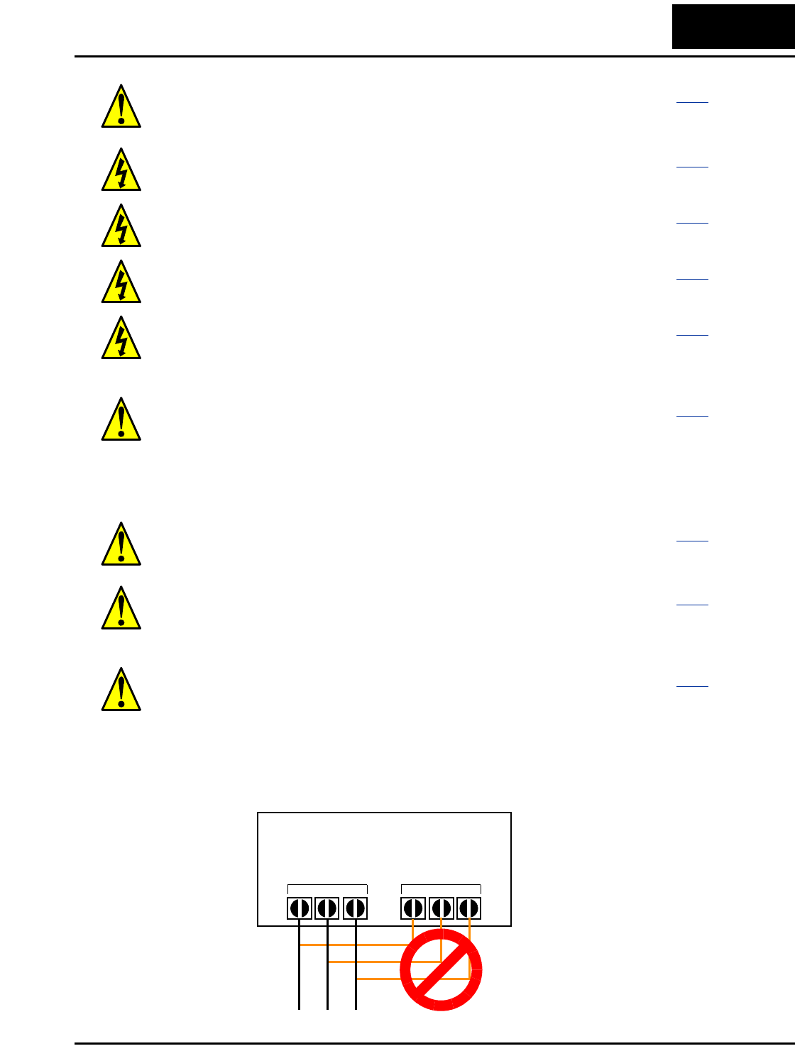
CAUTION: If you power a 3-phase-only inverter with single phase
power, you must derate the output current. Be sure to call your Hitachi
distributor for assistence. Otherwise, there is the possibility of damage to
the inverter and the danger of fire.
.... 2–20
Power Input Output to Motor
L2002 Inverter
vi
Powerup Test Caution Messages
CAUTION: Be sure not to connect an AC power supply to the output
terminals. Otherwise, there is the possibility of damage to the inverter
and the danger of injury and/or fire.
..... 2–20
CAUTION: Remarks for using ground fault interrupter breakers in the
main power supply: Adjustable frequency inverters with CE-filters (RFI-
filter) and shielded (screened) motor cables have a higher leakage current
toward Earth GND. Especially at the moment of switching ON this can
cause an inadvertent trip of ground fault interrupters. Because of the
rectifier on the input side of the inverter there is the possibility to stall the
switch-off function through small amounts of DC current. Please observe
the following: • Use only short time-invariant and pulse current-sensitive
ground fault interrupters with higher trigger current. • Other components
should be secured with separate ground fault interrupters. • Ground fault
interrupters in the power input wiring of an inverter are not an absolute
protection against electric shock.
..... 2–20
CAUTION: Be sure to install a fuse in each phase of the main power
supply to the inverter. Otherwise, there is the danger of fire.
..... 2–20
CAUTION: For motor leads, ground fault interrupter breakers and
electromagnetic contactors, be sure to size these components properly
(each must have the capacity for rated current and voltage). Otherwise,
there is the danger of fire.
..... 2–20
CAUTION: The heat sink fins will have a high temperature. Be careful
not to touch them. Otherwise, there is the danger of getting burned.
..... 2–23
CAUTION: The operation of the inverter can be easily changed from low
speed to high speed. Be sure to check the capability and limitations of the
motor and machine before operating the inverter. Otherwise, there is the
danger of injury.
..... 2–23
CAUTION: If you operate a motor at a frequency higher than the inverter
standard default setting (50Hz/60Hz), be sure to check the motor and
machine specifications with the respective manufacturer. Only operate
the motor at elevated frequencies after getting their approval. Otherwise,
there is the danger of equipment damage and/or injury.
.... 2–23,
..... 2–29
CAUTION: Check the following before and during the powerup test.
Otherwise, there is the danger of equipment damage. • Is the shorting bar
between the [+1] and [+] terminals installed? DO NOT power or operate
the inverter if the jumper is removed. • Is the direction of the motor
rotation correct? • Did the inverter trip during acceleration or decelera-
tion? • Were the rpm and frequency meter readings as expected? • Were
there any abnormal motor vibrations or noise?
..... 2–23
L2002 Inverter vii
Warnings for Configuring Drive Parameters
Cautions for Configuring Drive Parameters
Warnings for Operations and Monitoring
WARNING: When parameter B012, level of electronic thermal setting, is
set to motor FLA rating (Full Load Ampere nameplate rating), the
inverter provides solid state motor overload protection at 115% of motor
FLA or equivalent. If parameter B012 exceeds the motor FLA rating, the
motor may overheat and be damaged. Parameter B012, level of electronic
thermal setting, is a variable parameter.
.... 3–36
CAUTION: Be careful to avoid specifying a braking time that is long
enough to cause motor overheating. If you use DC braking, we recom-
mend using a motor with a built-in thermistor, and wiring it to the
inverter’s thermistor input (see “Thermistor Thermal Protection” on
page 4–25). Also refer to the motor manufacturer’s specifications for
duty-cycle recommendations during DC braking.
.... 3–21
WARNING: Be sure to turn ON the input power supply only after closing
the front case. While the inverter is energized, be sure not to open the
front case. Otherwise, there is the danger of electric shock.
...... 4–3
WARNING: Be sure not to operate electrical equipment with wet hands.
Otherwise, there is the danger of electric shock.
...... 4–3
WARNING: While the inverter is energized, be sure not to touch the
inverter terminals even when the motor is stopped. Otherwise, there is the
danger of electric shock.
...... 4–3
WARNING: If the Retry Mode is selected, the motor may suddenly
restart after a trip stop. Be sure to stop the inverter before approaching the
machine (be sure to design the machine so that safety for personnel is
secure even if it restarts.) Otherwise, it may cause injury to personnel.
...... 4–3
WARNING: If the power supply is cut OFF for a short period of time, the
inverter may restart operation after the power supply recovers if the Run
command is active. If a restart may pose danger to personnel, so be sure
to use a lock-out circuit so that it will not restart after power recovery.
Otherwise, it may cause injury to personnel.
...... 4–3
WARNING: The Stop Key is effective only when the Stop function is
enabled. Be sure to enable the Stop Key separately from the emergency
stop. Otherwise, it may cause injury to personnel.
...... 4–3
WARNING: During a trip event, if the alarm reset is applied and the Run
command is present, the inverter will automatically restart. Be sure to
apply the alarm reset only after verifying the Run command is OFF.
Otherwise, it may cause injury to personnel.
...... 4–3

viii
Cautions for Operations and Monitoring
WARNING: Be sure not to touch the inside of the energized inverter or to
put any conductive object into it. Otherwise, there is a danger of electric
shock and/or fire.
....... 4–3
WARNING: If power is turned ON when the Run command is already
active, the motor will automatically start and injury may result. Before
turning ON the power, confirm that the RUN command is not present.
....... 4–3
WARNING: When the Stop key function is disabled, pressing the Stop
key does not stop the inverter, nor will it reset a trip alarm.
....... 4–3
WARNING: Be sure to provide a separate, hard-wired emergency stop
switch when the application warrants it.
....... 4–3
WARNING: If the power is turned ON and the Run command is already
active, the motor starts rotation and is dangerous! Before turning power
ON, confirm that the Run command is not active.
..... 4–12
WARNING: After the Reset command is given and the alarm reset
occurs, the motor will restart suddenly if the Run command is already
active. Be sure to set the alarm reset after verifying that the Run
command is OFF to prevent injury to personnel.
..... 4–24
CAUTION: The heat sink fins will have a high temperature. Be careful
not to touch them. Otherwise, there is the danger of getting burned.
....... 4–2
CAUTION: The operation of the inverter can be easily changed from low
speed to high speed. Be sure check the capability and limitations of the
motor and machine before operating the inverter. Otherwise, it may cause
injury to personnel.
....... 4–2
CAUTION: If you operate a motor at a frequency higher than the inverter
standard default setting (50Hz/60Hz), be sure to check the motor and
machine specifications with the respective manufacturer. Only operate
the motor at elevated frequencies after getting their approval. Otherwise,
there is the danger of equipment damage.
....... 4–2
CAUTION: It is possible to damage the inverter or other devices if your
application exceeds the maximum current or voltage characteristics of a
connection point.
....... 4–4
CAUTION: Be sure to turn OFF power to the inverter before changing
the SR/SK switch position. Otherwise, damage to the inverter circuitry
may occur.
....... 4–9
CAUTION: Be careful not to turn PID Clear ON and reset the integrator
sum when the inverter is in Run Mode (output to motor is ON). Other-
wise, this could cause the motor to decelerate rapidly, resulting in a trip.
..... 4–28
L2002 Inverter ix
Warnings and Cautions for Troubleshooting and Maintenance
General Warnings and Cautions
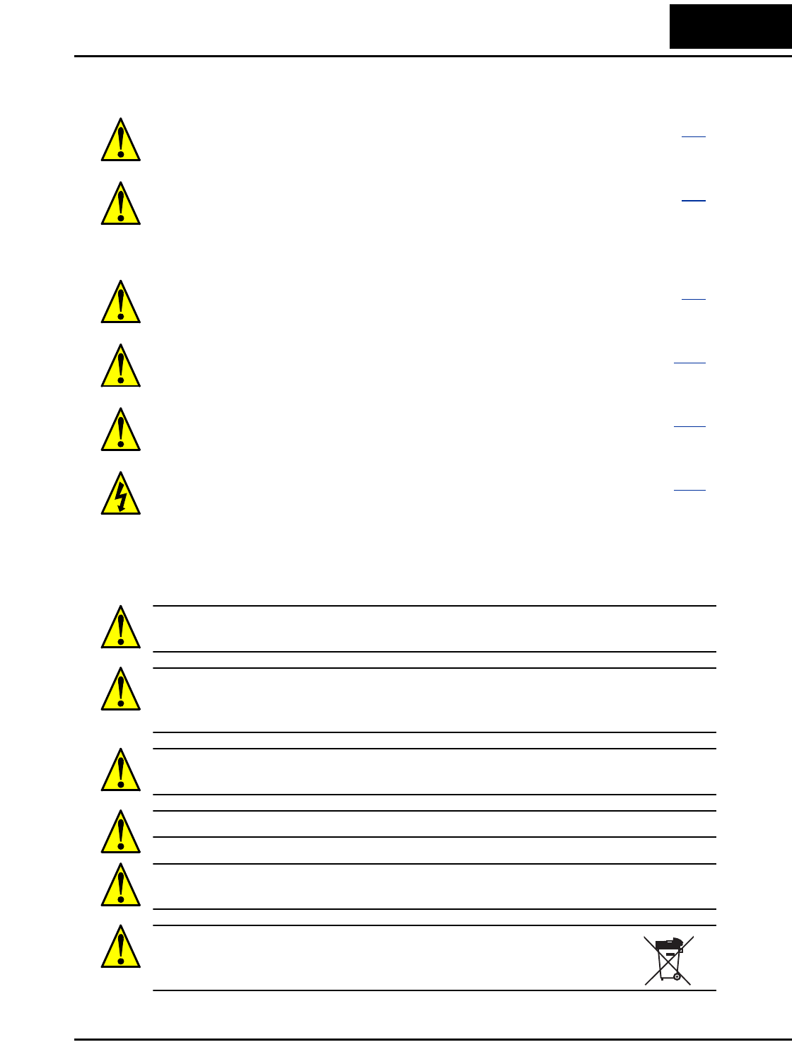
WARNING: Never modify the unit. Otherwise, there is a danger of electric shock and/
or injury.
CAUTION: Withstand voltage tests and insulation resistance tests (HIPOT) are
executed before the units are shipped, so there is no need to conduct these tests before
operation.
CAUTION: Do not attach or remove wiring or connectors when power is applied. Also,
do not check signals during operation.
CAUTION: Be sure to connect the grounding terminal to earth ground.
CAUTION: When inspecting the unit, be sure to wait five minutes after tuning OFF the
power supply before opening the cover.
CAUTION: Do do not discard the inverter with household waste.
Contact an industrial waste management company in your area who can
treat industrial waste without polluting the environment.
WARNING: Wait at least five (5) minutes after turning OFF the input
power supply before performing maintenance or an inspection. Other-
wise, there is the danger of electric shock.
...... 6–2
WARNING: Make sure that only qualified personnel will perform
maintenance, inspection, and part replacement. Before starting to work,
remove any metallic objects from your person (wristwatch, bracelet,
etc.). Be sure to use tools with insulated handles. Otherwise, there is a
danger of electric shock and/or injury to personnel.
...... 6–2
WARNING: Never remove connectors by pulling on its wire leads (wires
for cooling fan and logic P.C.board). Otherwise, there is a danger of fire
due to wire breakage and/or injury to personnel.
...... 6–2
CAUTION: Do not connect the megger to any control circuit terminals
such as intelligent I/O, analog terminals, etc. Doing so could cause
damage to the inverter.
.... 6–10
CAUTION: Never test the withstand voltage (HIPOT) on the inverter.
The inverter has a surge protector between the main circuit terminals
above and the chassis ground.
.... 6–10
HIGH VOLTAGE: Be careful not to touch wiring or connector terminals
when working with the inverters and taking measurements. Be sure to
place the measurement circuitry components above in an insulated
housing before using them.
.... 6–14
x
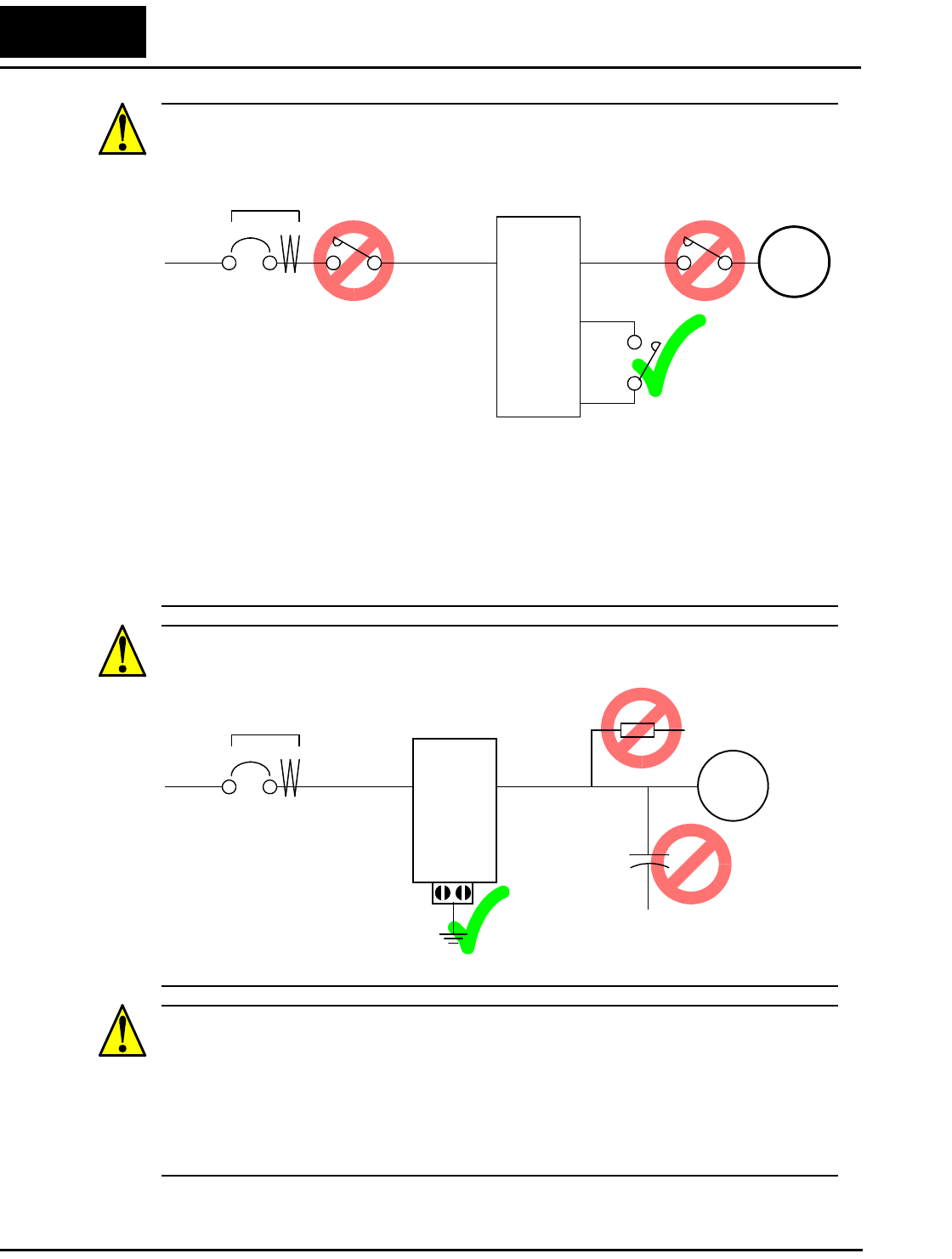
CAUTION: Do not stop operation by switching OFF electromagnetic contactors on the
primary or secondary sides of the inverter.
When there has been a sudden power failure while an operation instruction is active, then
the unit may restart operation automatically after the power failure has ended. If there is
a possibility that such an occurrence may harm humans, then install an electromagnetic
contactor (Mgo) on the power supply side, so that the circuit does not allow automatic
restarting after the power supply recovers. If the optional remote operator is used and the
retry function has been selected, this will also cause automatic restarting when a Run
command is active. So, please be careful.
CAUTION: Do not insert leading power factor capacitors or surge absorbers between
the output terminals of the inverter and motor.
CAUTION: MOTOR TERMINAL SURGE VOLTAGE SUPPRESSION FILTER
(For the 400 V CLASS)
In a system using an inverter with the voltage control PWM system, a voltage surge
caused by the cable constants such as the cable length (especially when the distance
between the motor and inverter is 10 m or more) and cabling method may occur at the
motor terminals. A dedicated filter of the 400 V class for suppressing this voltage surge
is available. Be sure to install a filter in this situation.
Power
Input
Inverter
L1, L2, L3
Ground fault
interrupter
U, V, W Motor
PCS
FW
Power
Input
Inverter
L1, L2, L3
Ground fault
interrupter
U, V, W Motor
GND lug
Surge absorber
Leading power
factor capacitor
L2002 Inverter xi
CAUTION: EFFECTS OF POWER DISTRIBUTION SYSTEM ON INVERTER
In the cases below involving a general-purpose inverter, a large peak current can flow on
the power supply side, sometimes destroying the converter module:
1. The unbalance factor of the power supply is 3% or higher.
2. The power supply capacity is at least 10 times greater than the inverter capacity (or
the power supply capacity is 500 kVA or more).
3. Abrupt power supply changes are expected, due to conditions such as:
a. Several inverters are interconnected with a short bus.
b. A thyristor converter and an inverter are interconnected with a short bus.
c. An installed phase advance capacitor opens and closes.
Where these conditions exist or when the connected equipment must be highly reliable,
you MUST install an input-side AC reactor of 3% (at a voltage drop at rated current)
with respect to the supply voltage on the power supply side. Also, where the effects of an
indirect lightning strike are possible, install a lightning conductor.
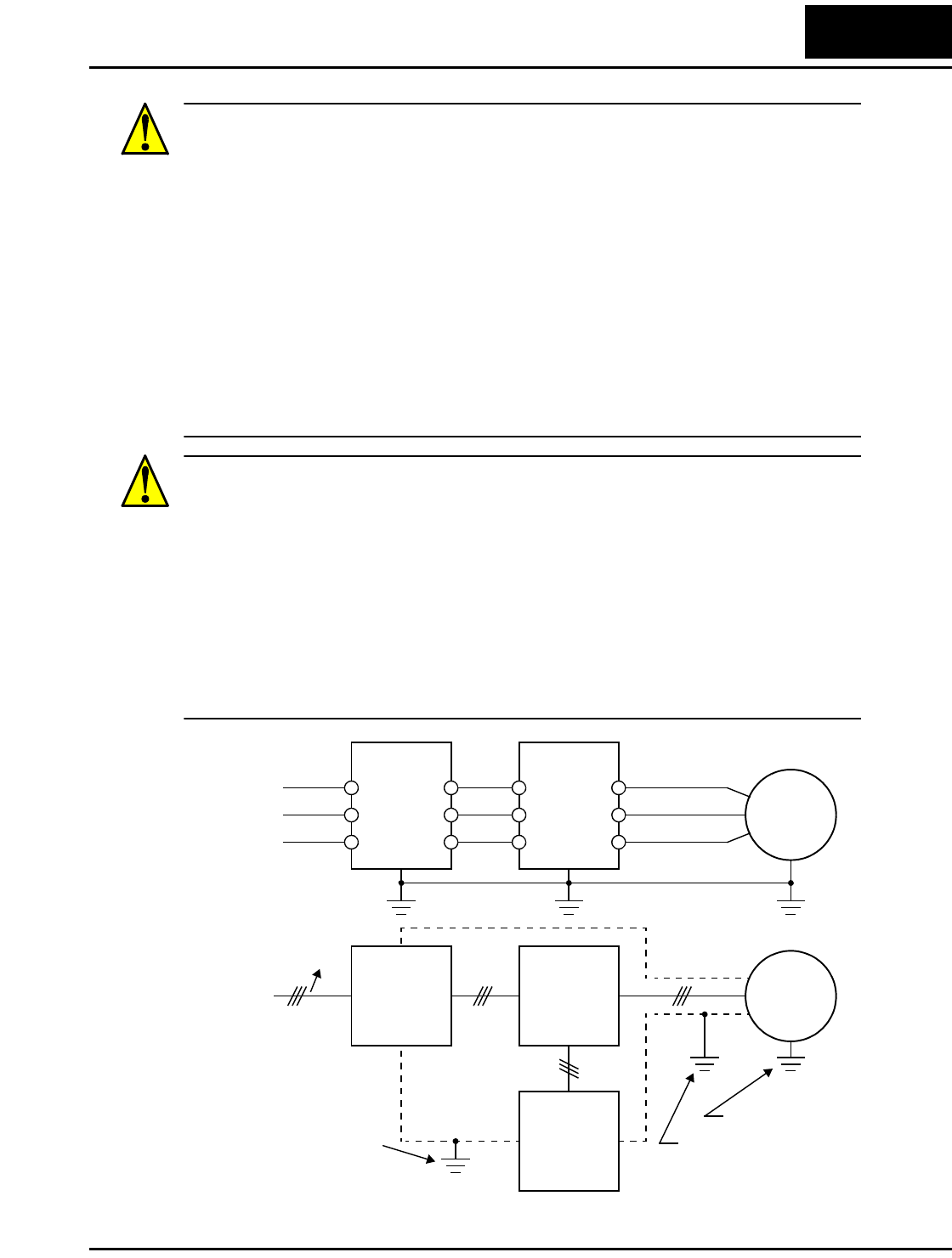
CAUTION: SUPPRESSION FOR NOISE INTERFERENCE FROM INVERTER
The inverter uses many semiconductor switching elements such as transistors and
IGBTs. Thus, a radio receiver or measuring instrument located near the inverter is
susceptible to noise interference.
To protect the instruments from erroneous operation due to noise interference, they
should be used well away from the inverter. It is also effective to shield the whole
inverter structure.
The addition of an EMI filter on the input side of the inverter also reduces the effect of
noise from the commercial power line on external devices.
Note that the external dispersion of noise from the power line can be minimized by
connecting an EMI filter on the primary side of inverter.
R1
S1
T1
R2
S2
T2
L1
L2
L3
U
V
W
EMI Filter Inverter
Motor
EMI Filter Inverter
noise
Motor
Remote
Operator
Completely ground the
enclosed panel, metal
screen, etc. with as
short a wire as possible.
Grounded frame
Conduit or shielded
cable—to be grounded
xii
CAUTION: When the EEPROM error E08 occurs, be sure to confirm the setting values
again.
CAUTION: When using normally closed active state settings (C011 to C015) for exter-
nally commanded Forward or Reverse terminals [FW] or [RV], the inverter may start
automatically when the external system is powered OFF or disconnected from the
inverter! So, do not use normally closed active state settings for Forward or Reverse
terminals [FW] or [RV] unless your system design protects against unintended motor
operation.
CAUTION: In all the illustrations in this manual, covers and safety devices are
occasionally removed to describe the details. While operating the product, make sure
that the covers and safety devices are placed as they were specified originally and
operate it according to the instruction manual.
UL® Cautions, Warnings, and Instructions
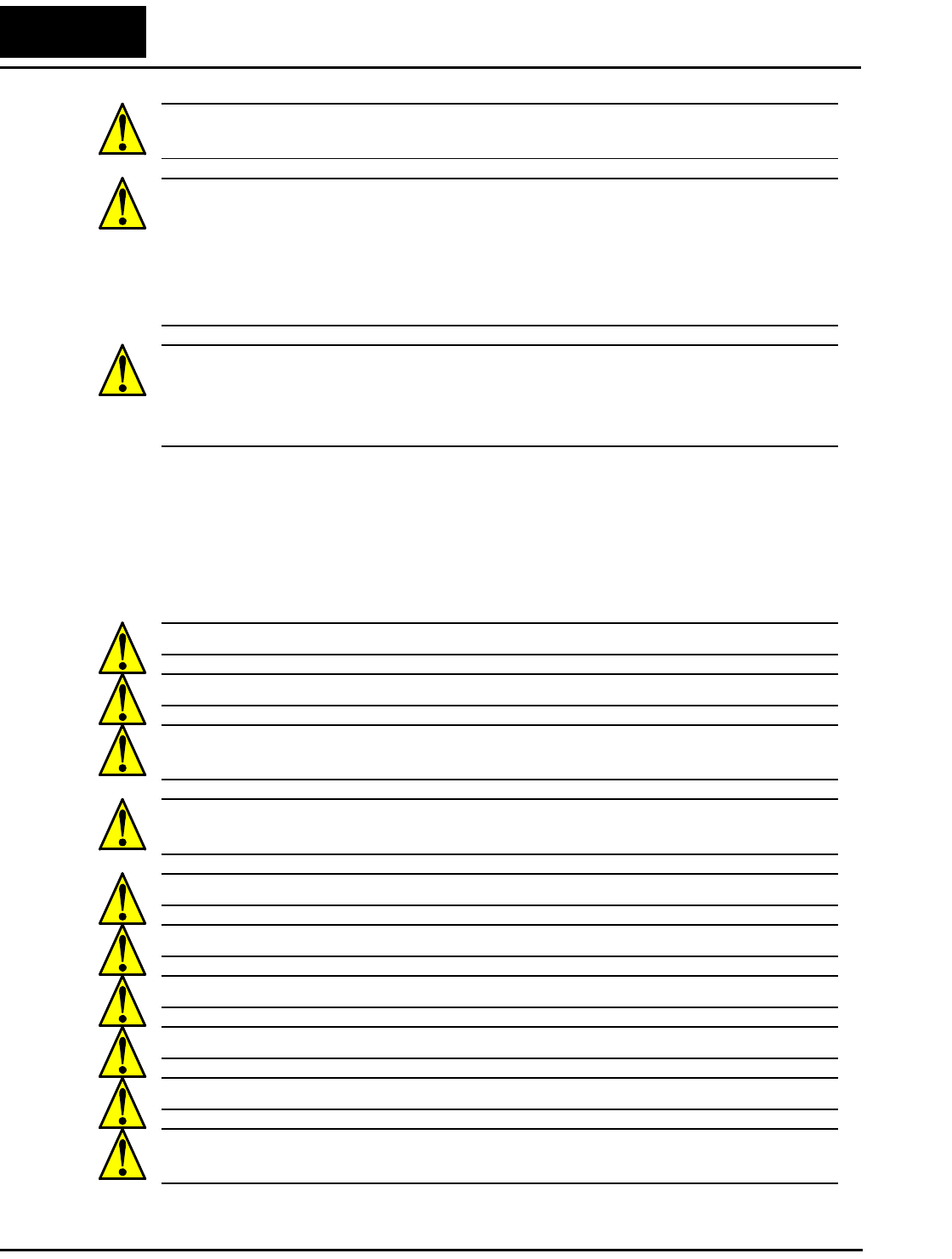
Wiring Warnings for Electrical Practices and Wire Sizes
The Warnings and instructions in this section summarize the procedures necessary to
ensure an inverter installation complies with Underwriters Laboratories® guidelines.
WARNING: “Use 60/75°C Cu wire only” or equivalent.
WARNING: “Open Type Equipment.”
WARNING: “Suitable for use on a circuit capable of delivering not more than 100,000
rms symmetrical amperes, 240 V maximum.” For models with suffix N or L.
WARNING: “Suitable for use on a circuit capable of delivering not more than 100,000
rms symmetrical amperes, 480 V maximum.” For models with suffix H.
WARNING: “Hot surface—risk of burn.”
WARNING: “Install device in pollution degree 2 environment.”
WARNING: “Maximum Surrounding Air Temperature 50°C” or equivalent.
WARNING: “Risk of electric shock—capacitor discharge time is at least 5 minutes.”
WARNING: “Solid state motor overload protection is provided in each model.”
WARNING: “Tightening torque and wire range for field wiring terminals are marked
adjacent to the terminal or on the wiring diagram.”
L2002 Inverter xiii
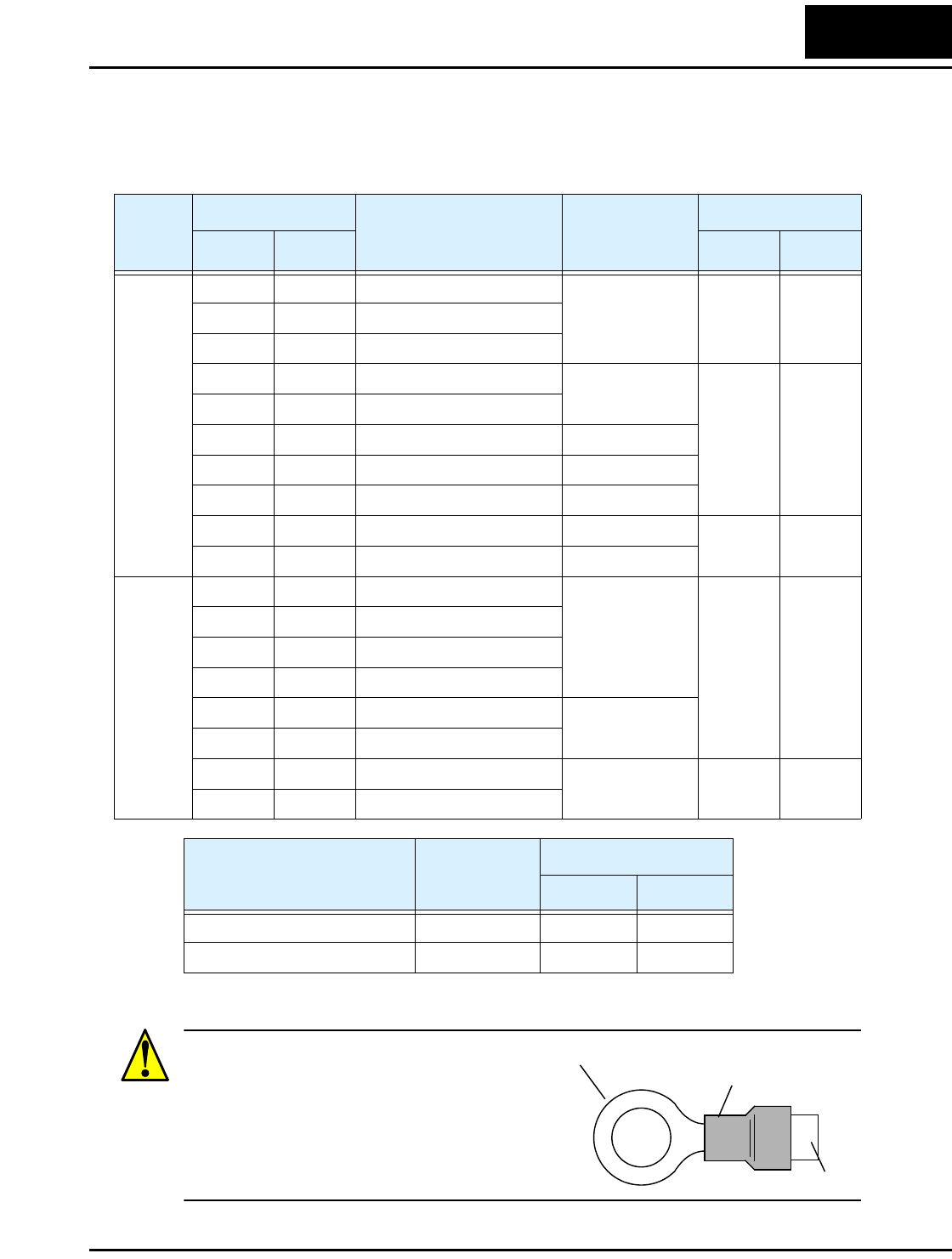
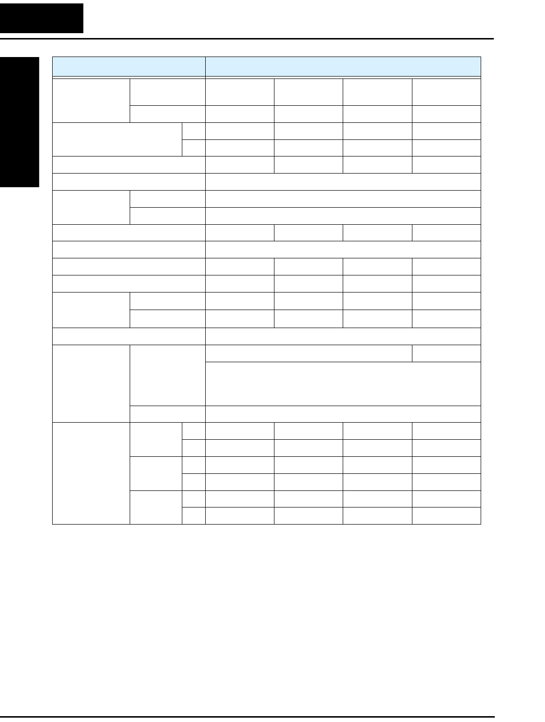
Terminal Tightening Torque and Wire Size
The wire size range and tightening torque for field wiring terminals are presented in the
tables below.
Wire Connectors
WARNING: Field wiring connections must be
made by a UL Listed and CSA Certified ring lug
terminal connector sized for the wire gauge being
used. The connector must be fixed using the
crimping tool specified by the connector
manufacturer.
Input
Voltage
Motor Output
Inverter Model
Power Terminal
Wiring Size
Range (AWG)
Torque
kW HP ft-lbs (N-m)
200V
0.2 1/4 L200-002NFE(F)2/NFU2
16 0.6 0.80.4 1/2 L200-004NFE(F)2/NFU2
0.55 3/4 L200-005NFE(F)2
0.75 1 L200-007NFE(F)2/NFU2 14
0.9 1.2
1.1 1 1/2 L200-011NFE(F)2
1.5 2 L200-015NFE(F)2/NFU2 12
2.2 3 L200-022NFE(F)2/NFU2 10
3.7 5 L200-037LFU2 12
5.5 7 1/2 L200-055LFU2 10 1.5 2.0
7.5 10 L200-075LFU2 8
400V
0.4 1/2 L200-004HFE(F)2/HFU2
16
0.9 1.2
0.75 1 L200-007HFE(F)2/HFU2
1.5 2 L200-015HFE(F)2/HFU2
2.2 3 L200-022HFE(F)2/HFU2
3.0 4 L200-030HFE(F)2 14
4.0 5 L200-040HFE(F)2/HFU2
5.5 7 1/2 L200-055HFE(F)2/HFU2 12 1.5 2.0
7.5 10 L200-075HFE(F)2/HFU2
Terminal Connector Wiring Size
Range (AWG)
Torque
ft-lbs (N-m)
Logic/Analog connector 30—16 0.16—0.19 0.22—0.25
Relay connector 30—14 0.37—0.44 0.5—0.6
Cable
Terminal (ring lug)
Cable support
xiv
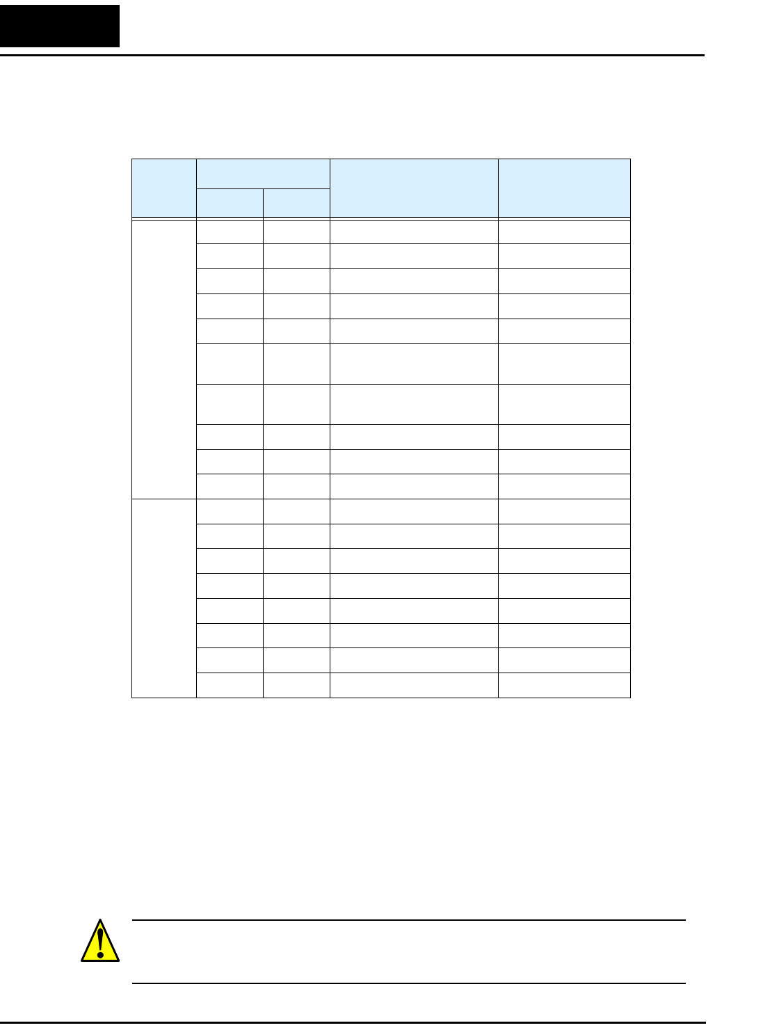
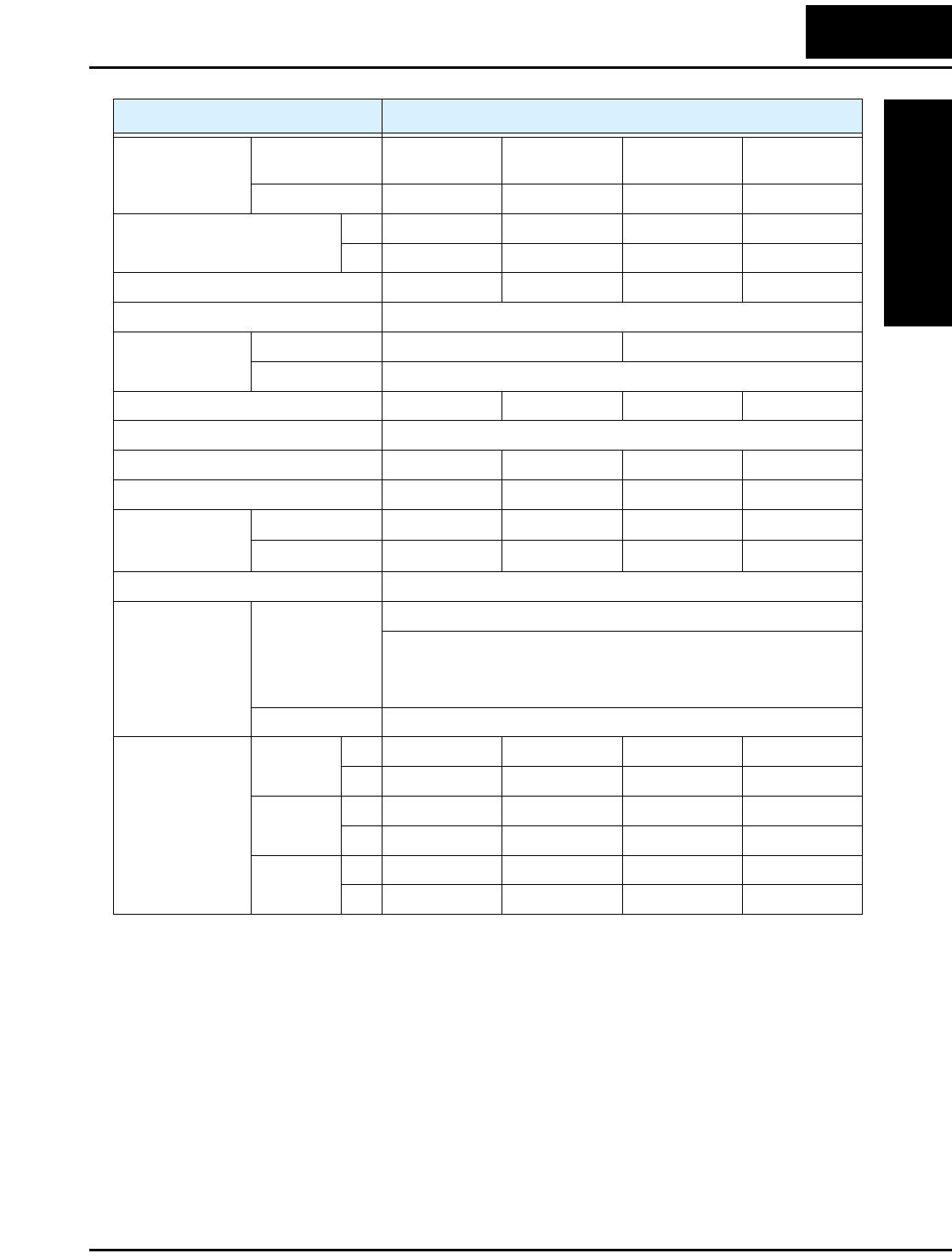
Fuse and Circuit Breaker Sizes
The inverter’s input power wiring must include UL Listed, dual-element, 600V fuses, or
UL Listed, inverse-time, 600V circuit breakers.
Motor Overload Protection
Hitachi L2002 inverters provide solid state motor overload protection, which depends on
the proper setting of the following parameters:
• B012 “electronic overload protection”
• B212 “electronic overload protection, 2nd motor”
Set the rated current [Amperes] of the motor(s) with the above parameters. The setting
range is 0.2 * rated current to 1.2 * rated current.
WARNING: When two or more motors are connected to the inverter, they cannot be
protected by the electronic overload protection. Install an external thermal relay on each
motor.
Input
Voltage
Motor Output
Inverter Model Ampere Rating for
Fuse or Breaker
kW HP
200V
0.2 1/4 L200-002NFE(F)2/NFU2 10
0.4 1/2 L200-004NFE(F)2/NFU2 10
0.55 3/4 L200-005NFE(F)2 10
0.75 1 L200-007NFE(F)2/NFU2 15
1.1 1 1/2 L200-011NFE(F)2 15
1.5 2 L200-015NFE(F)2/NFU2 20 (single ph.)
15 (three ph.)
2.2 3 L200-022NFE(F)2/NFU2 30 (single ph.)
20 (three ph.)
3.7 5 L200-037LFU2 30
5.5 7 1/2 L200-055LFU2 40
7.5 10 L200-075LFU2 50
400V
0.4 1/2 L200-004HFE(F)2/HFU2 3
0.75 1 L200-007HFE(F)2/HFU2 6
1.5 2 L200-015HFE(F)2/HFU2 10
2.2 3 L200-022HFE(F)2/HFU2 10
3.0 4 L200-030HFE(F)2 15
4.0 5 L200-040HFE(F)2/HFU2 15
5.5 7 1/2 L200-055HFE(F)2/HFU2 20
7.5 10 L200-075HFE(F)2/HFU2 25

xv
L2002 Inverter
Safety Messages
Hazardous High Voltage i
General Precautions - Read These First! ii
Index to Warnings and Cautions in This Manual iv
General Warnings and Cautions ix
UL® Cautions, Warnings, and Instructions xii
Table of Contents
Revisions xvii
Contact Information xviii
Chapter 1: Getting Started
Introduction 1–2
Inverter Specifications 1–5
Introduction to Variable-Frequency Drives 1–18
Frequently Asked Questions 1–23
Chapter 2: Inverter Mounting and Installation
Orientation to Inverter Features 2–2
Basic System Description 2–7
Step-by-Step Basic Installation 2–8
Powerup Test 2–22
Using the Front Panel Keypad 2–24
Chapter 3: Configuring Drive Parameters
Choosing a Programming Device 3–2
Using Keypad Devices 3–3
“D” Group: Monitoring Functions 3–6
“F” Group: Main Profile Parameters 3–9
“A” Group: Standard Functions 3–10
“B” Group: Fine Tuning Functions 3–33
“C” Group: Intelligent Terminal Functions 3–47
“H” Group: Motor Constants Functions 3–63
“P” Group: Expansion Card Functions 3–64
Table of Contents

xvi
Chapter 4: Operations and Monitoring
Introduction 4–2
Connecting to PLCs and Other Devices 4–4
Control Logic Signal Specifications 4–6
Intelligent Terminal Listing 4–7
Using Intelligent Input Terminals 4–9
Using Intelligent Output Terminals 4–35
Analog Input Operation 4–53
Analog Output Operation 4–55
PID Loop Operation 4–56
Configuring the Inverter for Multiple Motors 4–58
Chapter 5: Inverter System Accessories
Introduction 5–2
Component Descriptions 5–3
Dynamic Braking 5–5
Chapter 6: Troubleshooting and Maintenance
Troubleshooting 6–2
Monitoring Trip Events, History, & Conditions 6–5
Restoring Factory Default Settings 6–8
Maintenance and Inspection 6–9
Warranty 6–16
Appendix A: Glossary and Bibliography
Glossary A–2
Bibliography A–8
Appendix B: ModBus Network Communications
Introduction B–2
Connecting the Inverter to ModBus B–3
Network Protocol Reference B–6
ModBus Data Listing B–19
Appendix C: Drive Parameter Settings Tables
Introduction C–2
Parameter Settings for Keypad Entry C–2
Appendix D: CE–EMC Installation Guidelines
CE–EMC Installation Guidelines D–2
Hitachi EMC Recommendations D–6
Index

L2002 Inverter xvii
Revisions
Revision History Table
No. Revision Comments Date of Issue Operation
Manual No.
Initial release of manual NB675X Sept. 2006 NB675X

xviii
Contact Information
NOTE: To receive technical support for the Hitachi inverter you purchased, contact the
Hitachi inverter dealer from whom you purchased the unit, or the sales office or factory
contact listed above. Please be prepared to provide the following inverter nameplate
information:
1. Model
2. Date of purchase
3. Manufacturing number (MFG No.)
4. Symptoms of any inverter problem
If any inverter nameplate information is illegible, please provide your Hitachi contact
with any other legible nameplate items. To reduce unpredictable downtime, we recom-
mend that you stock a spare inverter.
Hitachi America, Ltd.
Power and Industrial Division
50 Prospect Avenue
Tarrytown, NY 10591
U.S.A.
Phone: +1-914-631-0600
Fax: +1-914-631-3672
Hitachi Australia Ltd.
Level 3, 82 Waterloo Road
North Ryde, N.S.W. 2113
Australia
Phone: +61-2-9888-4100
Fax: +61-2-9888-4188
Hitachi Europe GmbH
Am Seestern 18
D-40547 Düsseldorf
Germany
Phone: +49-211-5283-0
Fax: +49-211-5283-649
Hitachi Industrial Equipment Systems Co., Ltd.
AKS Building, 3, Kanda Neribei-cho
Chiyoda-ku, Tokyo, 101-0022
Japan
Phone: +81-3-4345-6910
Fax: +81-3-4345-6067
Hitachi Asia Ltd.
16 Collyer Quay
#20-00 Hitachi Tower, Singapore 049318
Singapore
Phone: +65-538-6511
Fax: +65-538-9011
Hitachi Industrial Equipment Systems Co, Ltd.
Narashino Division
1-1, Higashi-Narashino 7-chome
Narashino-shi, Chiba 275-8611
Japan
Phone: +81-47-474-9921
Fax: +81-47-476-9517
Hitachi Asia (Hong Kong) Ltd.
7th Floor, North Tower
World Finance Centre, Harbour City
Canton Road, Tsimshatsui, Kowloon
Hong Kong
Phone: +852-2735-9218
Fax: +852-2735-6793

Introduction
Getting Started
1–2
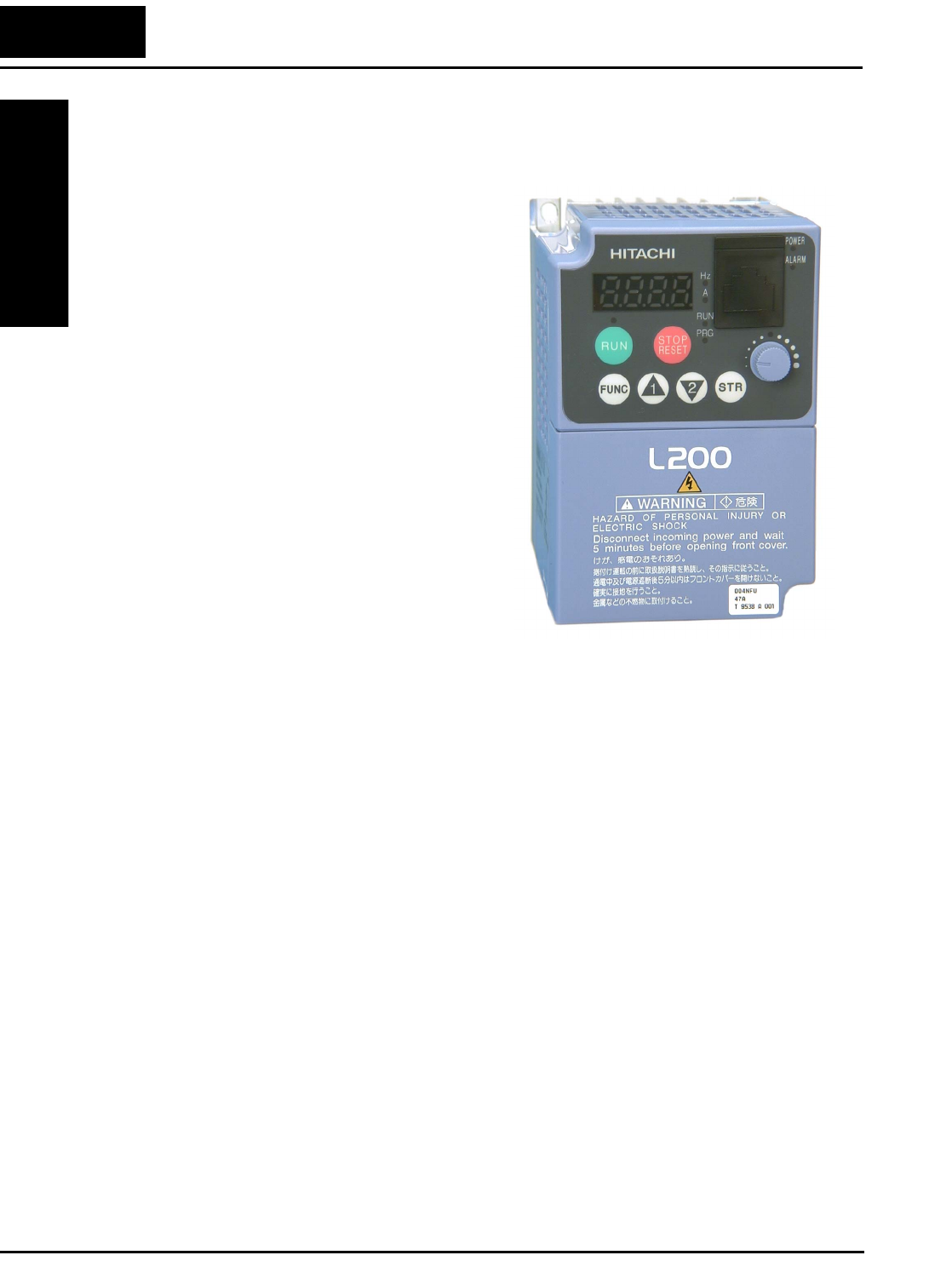
Introduction
Main Features
Congratulations on your purchase of an
L2002 Series Hitachi inverter! This inverter
drive features state-of-the-art circuitry and
components to provide high performance.
The housing footprint is exceptionally
small, given the size of the corresponding
motor. The Hitachi L2002 product line
includes more than a dozen inverter models
to cover motor sizes from 1/4 horsepower to
10 horsepower, in either 240 VAC or 480
VAC power input versions. The main
features are:
• 200V and 400V Class inverters
• US or EU versions available (country-
specific input voltage range and default
values)
• Built-in RS-485 MODBUS RTU as
standard
• New current limit function
• Sixteen programmable speed levels
• PID control adjusts motor speed automatically to maintain a process variable value
The design in Hitachi inverters overcomes many of the traditional trade-offs between
speed, torque and efficiency. The performance characteristics are:
• High starting torque of 100% at 6Hz
• Continuous operation at 100% torque within a 1:10 speed range (6/60 Hz / 5/50 Hz)
without motor derating
A full line of accessories from Hitachi is available to complete your motor application:
• Digital remote operator keypad
• Panel-mount keypad bezel kit and DIN rail mounting adapter (35mm rail size)
• Dynamic braking unit with resistors
• Radio noise filters
• CE compliance filters
L200-004NFU2
L2002 Inverter
Getting Started
1–3
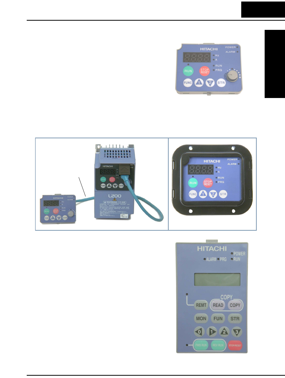
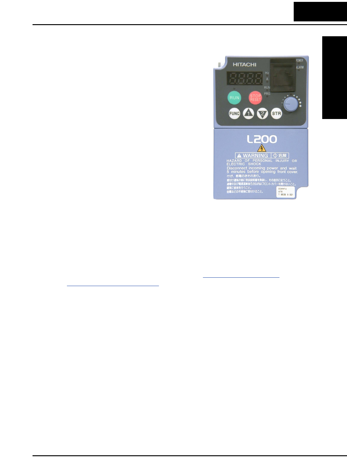
Operator Interface Options
The L2002 inverter can connect to an external
digital operator via the front panel serial port
connector. The separate keypad is shown to the
right (part no. OPE–SRmini). This allows you
to operate the inverter remotely, as shown
(below left). A cable (part no. ICS–1 or ICS–3,
1m or 3m) connects the modular connectors of
the keypad and inverter.
Hitachi provides a panel mount keypad kit
(below, right). It includes the mounting flange,
gasket, keypad, and other hardware. You can mount the keypad with the potentiometer
for a NEMA1 rated installation. The kit also provides for removing the potentiometer
knob to meet NEMA 4X requirements, as shown (part no. 4X–KITmini).
Digital Operator Copy Unit - The optional
digital operator / copy unit (part no. SRW-0EX)
is shown to the right. It has a 2-line display that
shows parameters by function code and by name.
It has the additional capability of reading
(uploading) the parameter settings in the inverter
into its memory. Then you can connect the copy
unit on another inverter and write (download) the
parameter settings into that inverter. OEMs will
find this unit particularly useful, as one can use a
single copy unit to transfer parameter settings
from one inverter to many.
Other digital operator interfaces may be available
from your Hitachi distributor for particular indus-
tries or international markets. Contact your
Hitachi distributor for further details.
OPE–SRmini
4X–KITmini
Cable
ICS–1 or
ICS–3
SRW–0EX
Introduction
Getting Started
1–4
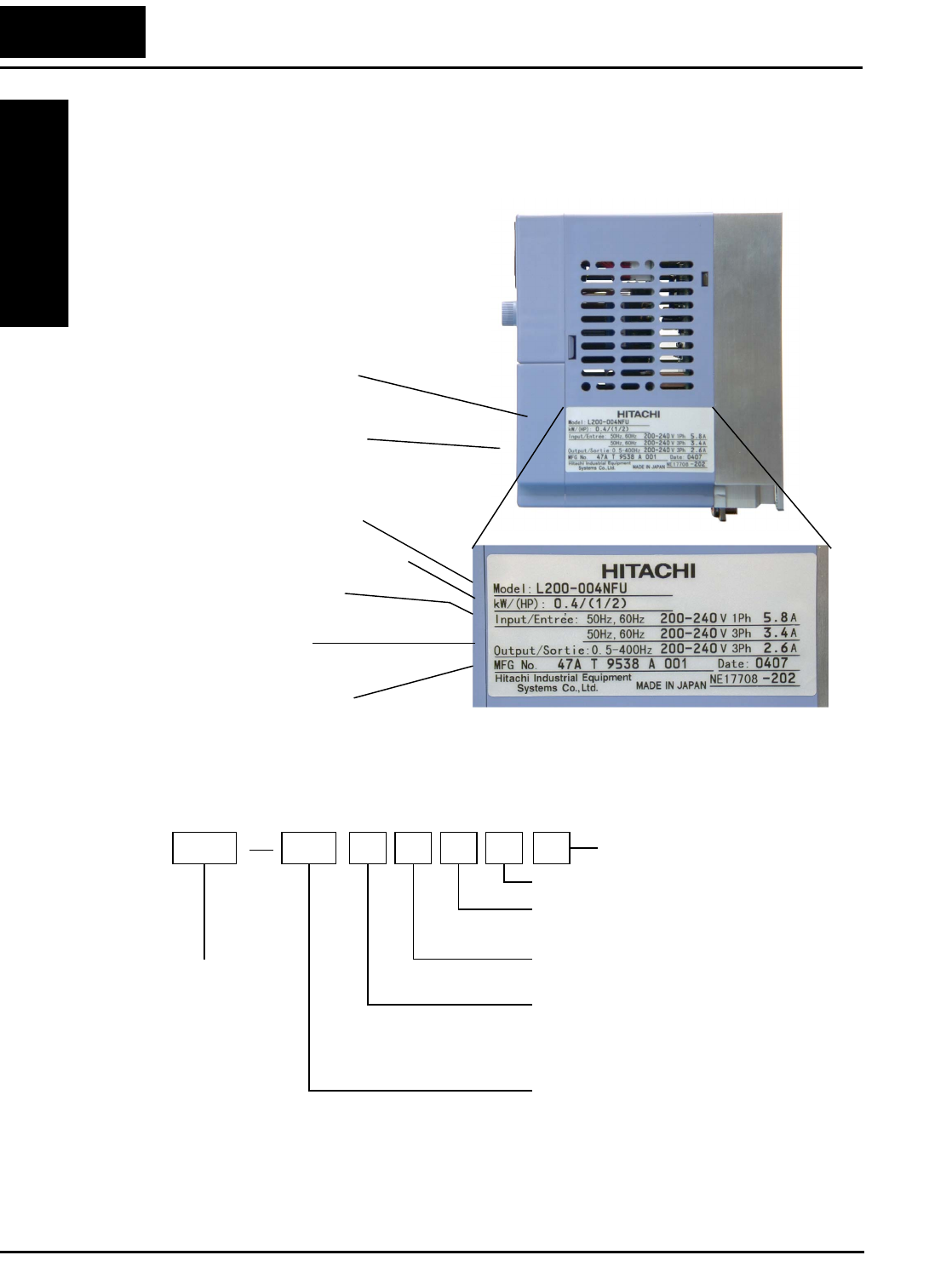
Inverter Specifications Label
The Hitachi L2002 inverters have product labels located on the right side of the housing,
as pictured below. Be sure to verify that the specifications on the labels match your
power source, motor, and application safety requirements.
Model Number Convention
The model number for a specific inverter contains useful information about its operating
characteristics. Refer to the model number legend below:
Power Input Rating:
frequency, voltage, phase, current
Inverter model number
Motor capacity for this model
Output Rating:
Frequency, voltage, current
Manufacturing codes:
Lot number, date, etc.
Specifications label
Regulatory agency approval
labels (opposite side)
L200 037 H F E
Restricted distribution:
E=Europe, U=USA, R=Japan
Input voltage:
N = single or three-phase 200V class
H = three-phase 400V class
L = three phase only, 200V class
Applicable motor capacity in kW
002 = 0.2 kW
004 = 0.4 kW
005 = 0.55 kW
007 = 0.75 kW
011 = 1.1 kW
015 = 1.5 kW
022 = 2.2 kW
030 = 3.0 kW
037 = 3.7 kW
040 = 4.0 kW
055 = 5.5 kW
075 = 7.5 kW
Configuration type
F = with digital operator (keypad)
Series name
F
EMC filter
2Version
L2002 Inverter
Getting Started
1–5
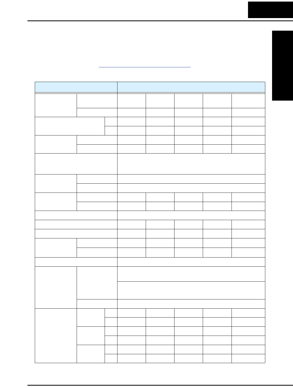
Inverter Specifications
Model-specific tables for 200V and 400V class inverters
The following tables are specific to L2002 inverters for the 200V and 400V class model
groups. Note that “General Specifications” on page 1–10 apply to both voltage class
groups. Footnotes for all specifications tables follow the table below.
Item 200V Class Specifications
L2002 inverters,
200V models
EU types 002NFEF2
002NFE2
004NFEF2
004NFE2
005NFEF2
005NFE2
007NFEF2
007NFE2
011NFEF2
011NFE2
USA type 002NFU2 004NFU2 — 007NFU2 —
Applicable motor size *2 kW 0.2 0.4 0.55 0.75 1.1
HP 1/4 1/2 3/4 1 1.5
Rated capacity
(kVA)
230V 0.5 1.0 1.1 1.5 1.9
240V 0.5 1.0 1.2 1.6 2.0
Rated input voltage 1-phase: 200 to 240V ±10%, 50/60 Hz ±5%,
3-phase: 200 to 240V ±10%, 50/60 Hz ±5%,
(037LFU2, 055LFU2, and 075LFU2 3-phase only)
Integrated EMC
filter
NFEF type Single phase filter, Category C3 *5
NFE, NFU types —
Rated input
current (A)
1-phase 3.1 5.8 6.7 9.0 11.2
3-phase 1.8 3.4 3.9 5.2 6.5
Rated output voltage *3 3-phase: 200 to 240V (proportional to input voltage)
Rated output current (A) 1.4 2.6 3.0 4.0 5.0
Efficiency at 100% rated output (%) 90.5 93.3 94.4 95.1 96.2
Watt loss,
approximate (W)
at 70% output 16 22 23 27 30
at 100% output 19 27 28 34 42
Starting torque *7 100% at 6Hz
Braking Dynamic
braking, approx.
% torque (short
time stop from
50 / 60 Hz) *8
100%: ≤ 50Hz
50%: ≤ 60Hz
Capacitive feedback type, dynamic braking unit and braking
resistor optional, individually installed
DC braking Variable operating frequency, time, and braking force
Weight NFEF type kg 0.8 0.95 0.95 1.4 1.4
lb 1.75 2.09 2.09 3.09 3.09
NFE type kg 0.7 0.85 0.85 1.8 1.8
lb 1.54 1.87 1.87 3.97 3.97
NFU type kg 0.7 0.85 — 1.8 —
lb 1.54 1.87 — 3.97 —
Inverter Specifications
Getting Started
1–6
Footnotes for the preceding table and the tables that follow:
Note 1: The protection method conforms to JEM 1030.
Note 2: The applicable motor refers to Hitachi standard 3-phase motor (4-pole). When
using other motors, care must be taken to prevent the rated motor current (50/
60 Hz) from exceeding the rated output current of the inverter.
Note 3: The output voltage decreases as the main supply voltage decreases (except
when using the AVR function). In any case, the output voltage cannot exceed
the input power supply voltage.
Note 4: To operate the motor beyond 50/60 Hz, consult the motor manufacturer for
the maximum allowable rotation speed.
Note 5: When using the inverter with 3-phase power input, remove the single phase
filter and install a 3-phase filter with the appropriate ratings.
Note 6: For achieving approved input voltage rating categories:
• 460 to 480 VAC – Over-voltage Category 2
• 380 to 460 VAC– Over-voltage Category 3
To meet the Over-voltage Category 3, insert an EN or IEC standard compliant
isolation transformer that is earth grounded and star connected (for Low
Voltage Directive).
Note 7: At the rated voltage when using a Hitachi standard 3-phase, 4-pole motor.
Note 8: The braking torque via capacitive feedback is the average deceleration torque
at the shortest deceleration (stopping from 50/60 Hz as indicated). It is not
continuous regenerative braking torque. The average deceleration torque
varies with motor loss. This value decreases when operating beyond 50 Hz. If
a large regenerative torque is required, the optional regenerative braking
resistor should be used.
Note 9: The frequency command is the maximum frequency at 9.8V for input voltage
0 to 10 VDC, or at 19.6 mA for input current 4 to 20 mA. If this characteristic
is not satisfactory for your application, contact your Hitachi sales representa-
tive.
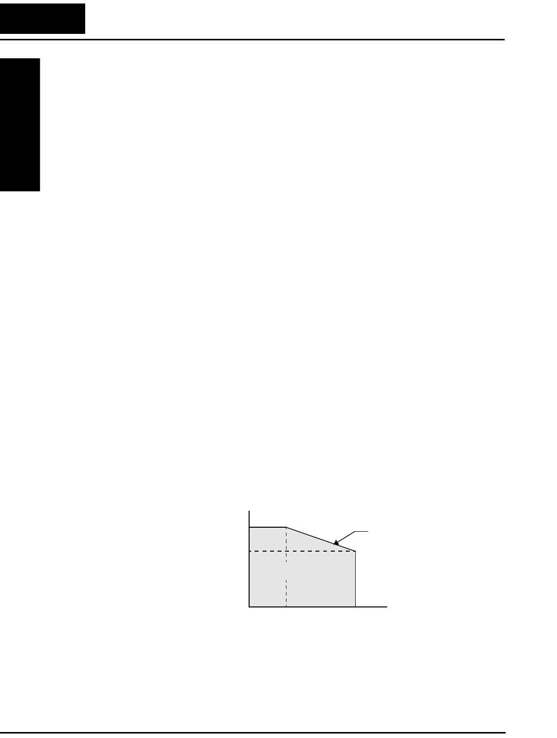
Note 10: If the inverter is operated outside the region shown in the graph to the right,
the inverter may be damaged or its service life may be shortened. Set B083
Carrier Frequency Adjustment in accordance with the expected output current
level.
Note 11: The storage temperature refers to the short-term temperature during transport.
Note 12: Conforms to the test method specified in JIS C0040 (1999). For the model
types excluded in the standard specifications, contact your Hitachi sales
representative.
Carrier frequency
Rated
current
100%
14.0
0
70%
5.0
Derating Curve
Operating region
Curve at 40°C
kHz
L2002 Inverter
Getting Started
1–7
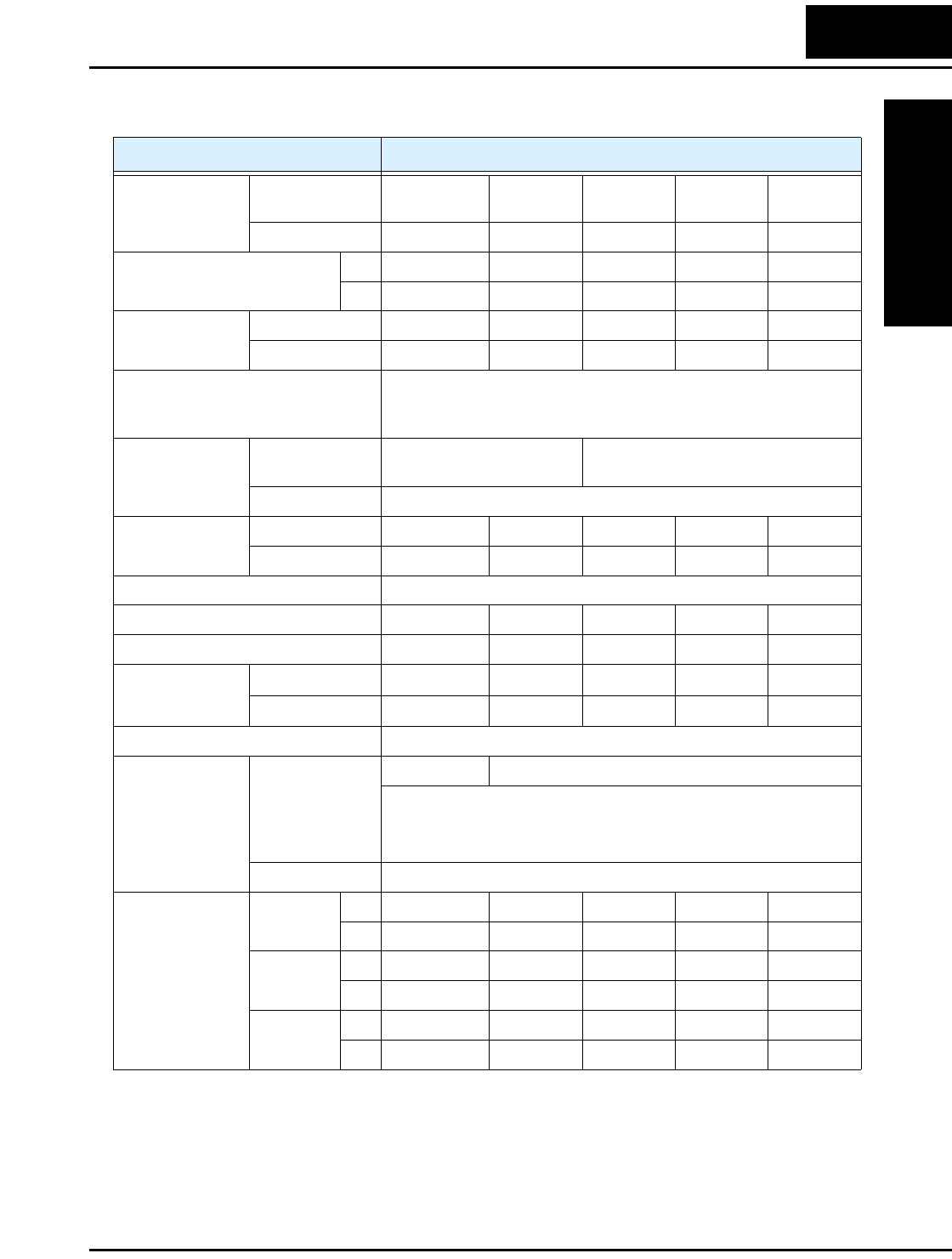
L2002 Inverter Specifications, continued...
Item 200V Class Specifications, continued
L2002 inverters,
200V models
EU types 015NFEF2
015NFE2
022NFEF2
022NFE2
———
USA type 015NFU2 022NFU2 037LFU2 055LFU2 075LFU2
Applicable motor size *2 kW 1.5 2.2 3.7 5.5 7.5
HP 2 3 5 7.5 10
Rated capacity
(kVA)
230V 2.8 3.9 6.3 9.5 12.7
240V 2.9 4.1 6.6 9.9 13.3
Rated input voltage 1-phase: 200 to 240V ±10%, 50/60 Hz ±5%,
3-phase: 200 to 240V ±10%, 50/60 Hz ±5%,
(037LFU2, 055LFU2, 075LFU2 3-phase only)
Integrated EMC
filter
NFEF type Single phase filter,
Category C3 *5
—
NFE, NFU types —
Rated input
current (A)
1-phase 16.0 22.5 — — —
3-phase 9.3 13.0 20.0 30.0 40.0
Rated output voltage *3 3-phase: 200 to 240V (proportional to input voltage)
Rated output current (A) 7.1 10.0 15.9 24 32
Efficiency at 100% rated output (%) 96.3 95.5 95.4 95.6 96.0
Watt loss,
approximate (W)
at 70% output 39 62 110 175 210
at 100% output 55 98 170 244 300
Starting torque *7 100% at 6Hz
Braking Dynamic
braking, approx.
% torque (short
time stop from
50 / 60 Hz) *8
50%: ≤ 60Hz 20%: ≤ 60Hz
Capacitive feedback type, dynamic braking unit and braking
resistor optional, individually installed
DC braking Variable operating frequency, time, and braking force
Weight NFEF type kg 1.9 1.9 — — —
lb 4.2 4.2 — — —
NFE type kg 1.8 1.8 — — —
lb 3.97 3.97 — — —
NFU type kg 1.8 1.8 1.9 5.5 5.7
lb 3.97 3.97 4.2 12.13 12.57
Inverter Specifications
Getting Started
1–8
Item 400V Class Specifications
L2002 inverters,
400V models
EU types 004HFEF2
004HFE2
007HFEF2
007HFE2
015HFEF2
015HFE2
022HFEF2
022HFE2
USA type 004HFU2 007HFU2 015HFU2 022HFU2
Applicable motor size *2 kW 0.4 0.75 1.5 2.2
HP 1/2 1 2 3
Rated capacity (460V) kVA 1.1 1.9 2.9 4.2
Rated input voltage *6 3-phase: 380 to 480V ±10%, 50/60 Hz ±5%
Integrated EMC
filter
HFEF type Three phase filter, Category C3 *5
HFE, HFU types —
Rated input current (A) 2.0 3.3 5.0 7.0
Rated output voltage *3 3-phase: 380 to 480V (proportional to input voltage)
Rated output current (A) 1.5 2.5 3.8 5.5
Efficiency at 100% rated output (%) 93.5 94.0 95.3 95.7
Watt loss,
approximate (W)
at 70% output 20 30 45 65
at 100% output 26 42 70 95
Starting torque *7 100% at 6Hz
Braking Dynamic
braking, approx.
% torque (short
time stop from
50 / 60 Hz) *8
50%: ≤ 60Hz 20%: ≤ 60Hz
Capacitive feedback type, dynamic braking unit and braking
resistor optional, individually installed
DC braking Variable operating frequency, time, and braking force
Weight HFEF type kg 1.4 1.8 1.9 1.9
lb 3.09 3.97 4.19 4.19
HFE type kg 1.3 1.7 1.8 1.8
lb 2.87 3.75 3.97 3.97
HFU type kg 1.3 1.7 1.8 1.8
lb 2.87 3.75 3.97 3.97
L2002 Inverter
Getting Started
1–9
Item 400V Class Specifications, continued
L2002 inverters,
400V models
EU types 030HFEF2
030HFE2
040HFEF2
040HFE2
055HFEF2
055HFE2
075HFEF2
075HFE2
USA type — 040HFU2 055HFU2 075HFU2
Applicable motor size *2 kW 3.0 4.0 5.5 7.5
HP 4 5 7.5 10
Rated capacity (460V) kVA 6.2 6.6 10.3 12.7
Rated input voltage *6 3-phase: 380 to 480V ±10%, 50/60 Hz ±5%
Integrated EMC
filter
HFEF type Three phase filter, Category C3 —
HFE, HFU types —
Rated input current (A) 10.0 11.0 16.5 20.0
Rated output voltage *3 3-phase: 380 to 480V (proportional to input voltage)
Rated output current (A) 7.8 8.6 13 16
Efficiency at 100% rated output (%) 95.7 95.9 96.6 97.0
Watt loss,
approximate (W)
at 70% output 90 95 135 165
at 100% output 130 150 187 227
Starting torque *7 100% at 6Hz
Braking Dynamic
braking, approx.
% torque (short
time stop from
50 / 60 Hz) *8
20%: ≤ 60Hz
Capacitive feedback type, dynamic braking unit and braking
resistor optional, individually installed
DC braking Variable operating frequency, time, and braking force
Weight HFEF type kg 1.9 1.9 5.5 5.7
lb 4.19 4.19 12.13 12.57
HFE type kg 1.8 1.8 3.5 5.6
lb 3.97 3.97 7.72 12.35
HFU type kg — 1.8 5.4 5.6
lb — 3.97 11.91 12.35
Inverter Specifications
Getting Started
1–10
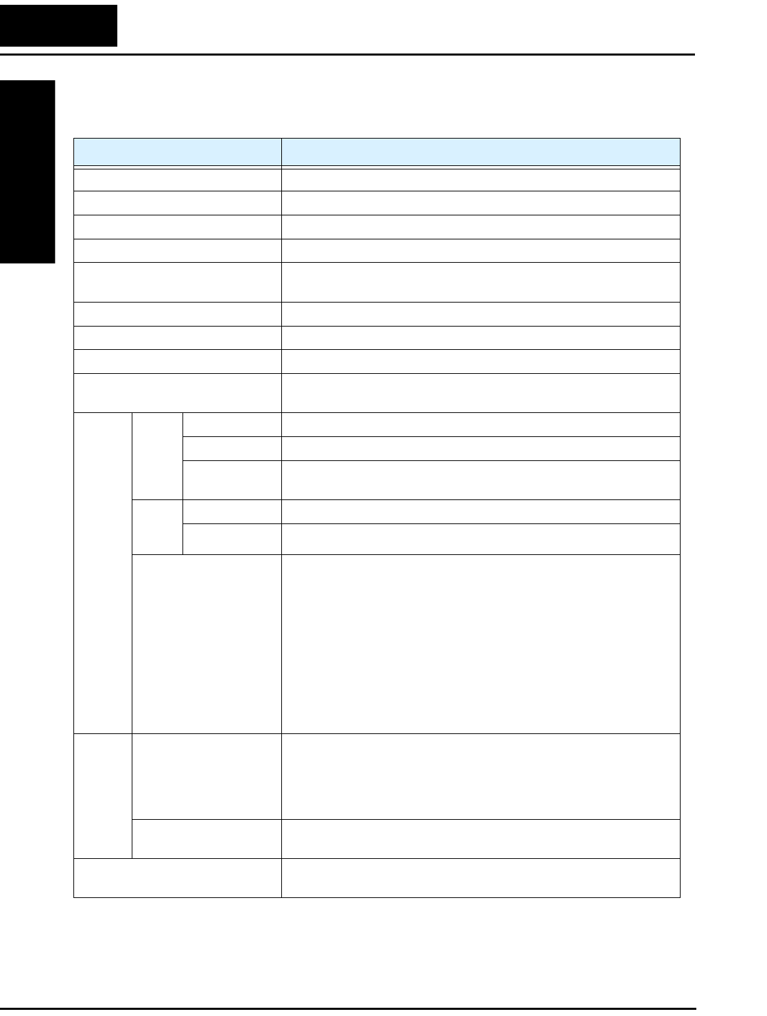
General Specifications
The following table applies to all L2002 inverters.
Item General Specifications
Protective housing *1 IP20
Control method Sinusoidal Pulse Width Modulation (PWM) control
Carrier frequency 2kHz to 14kHz (default setting: 5kHz)
Output frequency range *4 0.5 to 400 Hz
Frequency accuracy Digital command: 0.01% of the maximum frequency
Analog command: 0.1% of the maximum frequency (25°C ± 10°C)
Frequency setting resolution Digital: 0.1 Hz; Analog: max. frequency/1000
Volt./Freq. characteristic V/f optionally variable, V/f control (constant torque, reduced torque)
Overload capacity 150% of rated current for 1 minute
Acceleration/deceleration time 0.01 to 3000 seconds, linear and S-curve accel/decel, second
accel/decel setting available
Input
signal
Freq.
setting
Operator panel Up and Down keys / Value settings
Potentiometer Analog setting
External signal
*9
0 to 10 VDC (input impedance 10k Ohms), 4 to 20 mA (input
impedance 250 Ohms), Potentiometer (1k to 2k Ohms, 2W)
FWD/
REV
Run
Operator panel Run/Stop (Forward/Reverse run change by command)
External signal Forward run/stop, Reverse run/stop
Intelligent input
terminal
FW (forward run command), RV (reverse run command), CF1~CF4
(multi-stage speed setting), JG (jog command), DB (external
braking), SET (set second motor), 2CH (2-stage accel./decel.
command), FRS (free run stop command), EXT (external trip), USP
(startup function), SFT (soft lock), AT (analog current input select
signal), RS (reset), PTC (thermistor thermal protection), STA (start),
STP (stop), F/R (forward/reverse), PID (PID disable), PIDC (PID
reset), UP (remote control up function), DWN (remote control down
function), UDC (remote control data clearing), OPE (operator
control), ADD (ADD frequency enable), F-TM (force terminal
mode), RDY (quick start enable)
Output
signal
Intelligent output
terminal
RUN (run status signal), FA1,2 (frequency arrival signal), OL
(overload advance notice signal), OD (PID error deviation signal),
AL (alarm signal), Dc (analog input disconnect detect), FBV (PID
two-stage control output), NDc (network detection signal), LOG
(logic output), OPDc (option card detection signal)
Frequency monitor PWM output; Select analog output frequency monitor, analog output
current monitor or digital output frequency monitor
Alarm output contact ON for inverter alarm (1C contacts, both normally open or closed
avail.)
L2002 Inverter
Getting Started
1–11
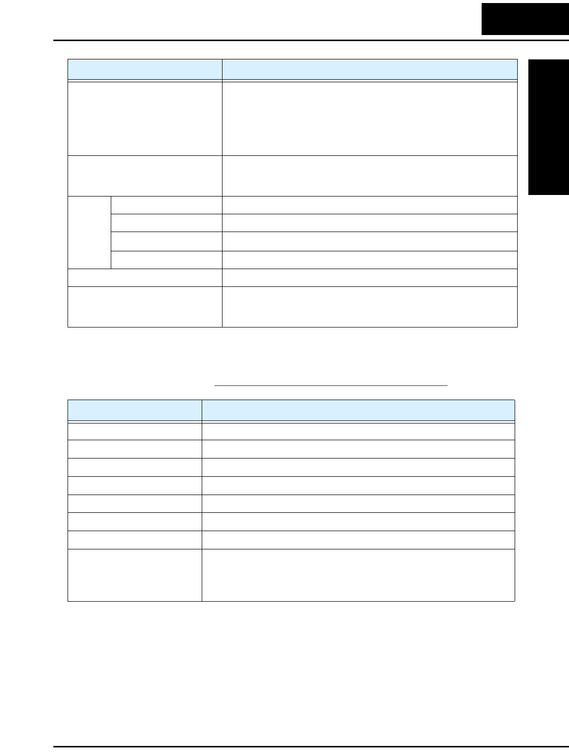
Signal Ratings
Detailed ratings are in “Control Logic Signal Specifications” on page 4–6.
Other functions AVR function, curved accel/decel profile, upper and lower limiters,
16-stage speed profile, fine adjustment of start frequency, carrier
frequency change (2 to 14 kHz) *10, frequency jump, gain and bias
setting, process jogging, electronic thermal level adjustment, retry
function, trip history monitor, 2nd setting selection, fan ON/OFF
selection
Protective function Over-current, over-voltage, under-voltage, overload, extreme high/
low temperature, CPU error, memory error, ground fault detection at
startup, internal communication error, electronic thermal
Operat-
ing
Environ
ment
Temperature Operating (ambient): -10 to 40°C (*10) / Storage: -25 to 60°C (*11)
Humidity 20 to 90% humidity (non-condensing)
Vibration *12 5.9 m/s2 (0.6G), 10 to 55 Hz
Location Altitude 1,000 m or less, indoors (no corrosive gasses or dust)
Coating color Blue (DIC 14 Version No. 436)
Options Remote operator unit, copy unit, cables for the units, braking unit,
braking resistor, AC reactor, DC reactor, noise filter, DIN rail
mounting
Item General Specifications
Signal / Contact Ratings
Built-in power for inputs 24VDC, 30 mA maximum
Discrete logic inputs 27VDC maximum
Discrete logic outputs 50mA maximum ON state current, 27 VDC maximum OFF state voltage
Analog output 0 to 10VDC, 1 mA
Analog input, current 4 to 19.6 mA range, 20 mA nominal
Analog input, voltage 0 to 9.6 VDC range, 10VDC nominal, input impedance 10 kΩ
+10V analog reference 10VDC nominal, 10 mA maximum
Alarm relay contacts 250 VAC, 2.5A (R load) max., 0.2A (I load, P.F.=0.4) max.
100 VAC, 10mA min.
30 VDC, 3.0A (R load) max., 0.7A (I load, P.F.=0.4) max.
5 VDC, 100mA min.

Inverter Specifications
Getting Started
1–12
Derating Curves
The maximum available inverter current output is limited by the carrier frequency and
ambient temperature. The carrier frequency is the inverter’s internal power switching
frequency, settable from 2 kHz to 14 kHz. Choosing a higher carrier frequency tends to
decrease audible noise, but it also increases the internal heating of the inverter, thus
decreasing (derating) the maximum current output capability. Ambient temperature is
the temperature just outside the inverter housing—such as inside the control cabinet
where the inverter is mounted. A higher ambient temperature decreases (derates) the
inverter’s maximum current output capacity.
An inverter may be mounted individually in an enclosure or side-by-side with other
inverter(s) as shown below. Side-by-side mounting causes greater derating than
mounting inverters separately. Graphs for either mounting method are included in this
section. Refer to “Ensure Adequate Ventilation” on page 2–11 for minimum clearance
dimensions for both mounting configurations.
Use the following derating curves to help determine the optimal carrier frequency setting
for your inverter and find the output current derating. Be sure to use the proper curve for
your particular L2002 inverter model number.
EnclosureEnclosure
Individual Mounting Side-by-side Mounting
L2002
12
RUN STOP
RESET
FUNC.
STR
HITACHI
POWER
ALARM
RUN
A
Hz
PRG
5 0.0
L2002
12
RUN STOP
RESET
FUNC.
STR
HITACHI
POWER
ALARM
RUN
A
Hz
PRG
5 0.0
L2002
12
RUN STOP
RESET
FUNC.
STR
HITACHI
POWER
ALARM
RUN
A
Hz
PRG
5 0.0
Ambient temperature 40°C max., individual mounting
Ambient temperature 50°C max., individual mounting
Ambient temperature 40°C max., side-by-side mounting
Legend for Graphs:
L2002 Inverter
Getting Started
1–13
Derating curves:
2468101214
70%
80%
90%
100%
95%
85%
75%
% of rated
output current
Carrier frequency
kHz
L200–002NFE(F)2/NFU2
2468101214
70%
80%
90%
100%
95%
85%
75%
% of rated
output current
Carrier frequency
kHz
L200–004NFE(F)2/
NFU2, –005NFE(F)2
2468101214
40%
60%
80%
100%
90%
70%
50%
% of rated
output current
Carrier frequency
kHz
L200–007NFE(F)2/
NFU2, –011NFE(F)2
Inverter Specifications
Getting Started
1–14
Derating curves, continued...
2468101214
70%
80%
90%
100%
95%
85%
75%
% of rated
output current
Carrier frequency
kHz
2468101214
70%
80%
90%
100%
95%
85%
75%
% of rated
output current
Carrier frequency
kHz
L200–015NFE(F)2/NFU2
L200–022NFE(F)2/NFU2
2468101214
40%
60%
80%
100%
90%
70%
50%
% of rated
output current
Carrier frequency
kHz
L200–037LFU2

L2002 Inverter
Getting Started
1–15
Derating curves, continued...
2468101214
40%
60%
80%
100%
90%
70%
50%
% of rated
output current
Carrier frequency
kHz
2468101214
40%
60%
80%
100%
90%
70%
50%
% of rated
output current
Carrier frequency
kHz
L200–055LFU2
L200–075LFU2
2468101214
40%
60%
80%
100%
90%
70%
50%
% of rated
output current
Carrier frequency
kHz
L200–004HFE(F)2/HFU2

Inverter Specifications
Getting Started
1–16
Derating curves, continued...
2468101214
40%
60%
80%
100%
90%
70%
50%
% of rated
output current
Carrier frequency
kHz
2468101214
40%
60%
80%
100%
90%
70%
50%
% of rated
output current
Carrier frequency
kHz
L200–007HFE(F)2/HFU2
L200–015HFE(F)2/HFU2
2468101214
40%
60%
80%
100%
90%
70%
50%
% of rated
output current
Carrier frequency
kHz
L200–022HFE(F)2/HFU2
L2002 Inverter
Getting Started
1–17
Derating curves, continued...
2468101214
40%
60%
80%
100%
90%
70%
50%
% of rated
output current
Carrier frequency
kHz
2468101214
40%
60%
80%
100%
90%
70%
50%
% of rated
output current
Carrier frequency
kHz
L200–030HFE(F)2,
-040HFE(F)/HFU2
L200–055HFE(F)2/HFU2
2468101214
40%
60%
80%
100%
90%
70%
50%
% of rated
output current
Carrier frequency
kHz
L200–075HFE(F)2/HFU2
Introduction to Variable-Frequency Drives
Getting Started
1–18
Introduction to Variable-Frequency Drives
The Purpose of Motor Speed Control for Industry
Hitachi inverters provide speed control for 3-phase AC induction motors. You connect
AC power to the inverter, and connect the inverter to the motor. Many applications
benefit from a motor with variable speed, in several ways:
• Energy savings - HVAC
• Need to coordinate speed with an adjacent process—textiles and printing presses
• Need to control acceleration and deceleration (torque)
• Sensitive loads - elevators, food processing, pharmaceuticals
What is an Inverter?
The term inverter and variable-frequency drive are related and somewhat interchange-
able. An electronic motor drive for an AC motor can control the motor’s speed by
varying the frequency of the power sent to the motor.
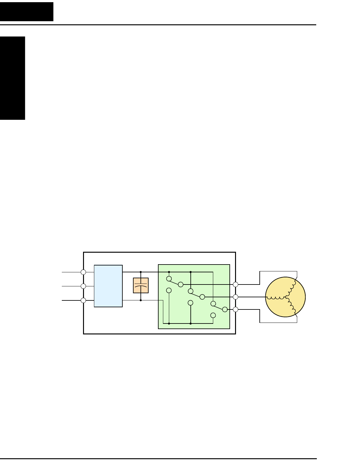
An inverter, in general, is a device that converts DC power to AC power. The figure
below shows how the variable-frequency drive employs an internal inverter. The drive
first converts incoming AC power to DC through a rectifier bridge, creating an internal
DC bus voltage. Then the inverter circuit converts the DC back to AC again to power the
motor. The special inverter can vary its output frequency and voltage according to the
desired motor speed.
The simplified drawing of the inverter shows three double-throw switches. In Hitachi
inverters, the switches are actually IGBTs (insulated gate bipolar transistors). Using a
commutation algorithm, the microprocessor in the drive switches the IGBTs on and off
at a very high speed to create the desired output waveforms. The inductance of the motor
windings helps smooth out the pulses.
Power
Input Inverter
L1 Motor
L2
L3
Rectifier
Variable-frequency Drive
Internal
DC Bus
+
+
–
U/T1
V/T2
W/T3
Converter

L2002 Inverter
Getting Started
1–19
Torque and Constant Volts/Hertz Operation
In the past, AC variable speed drives used an
open loop (scalar) technique to control speed.
The constant-volts-per-hertz operation
maintains a constant ratio between the applied
voltage and the applied frequency. With these
conditions, AC induction motors inherently
delivered constant torque across the operating
speed range. For some applications, this scalar
technique was adequate.
Today, with the advent of sophisticated micro-
processors and digital signal processors (DSPs),
it is possible to control the speed and torque of AC induction motors with unprecedented
accuracy. The L2002 utilizes these devices to perform complex mathematical calcula-
tions required to achieve superior performance. You can choose various torque curves to
fit the needs of your application. Constant torque applies the same torque level across the
frequency (speed) range. Variable torque, also called reduced torque, lowers the torque
delivered at mid-level frequencies. A torque boost setting will add additional torque in
the lower half of the frequency range for the constant and variable torque curves. With
the free-setting torque curve feature, you can specify a series of data points that will
define a custom torque curve to fit your application.
Inverter Input and Three-Phase Power
The Hitachi L2002 Series of inverters includes two sub-groups: the 200V class and the
400V class inverters. The drives described in this manual may be used in either the
United States or Europe, although the exact voltage level for commercial power may be
slightly different from country to country. Accordingly, a 200V class inverter requires
(nominal) 200 to 240VAC, and a 400V class inverter requires from 380 to 480VAC.
Some 200V class inverters will accept single-phase or three-phase power, but all 400V
class inverters require a three-phase power supply.
TIP: If your application only has single phase power available, refer to L2002 inverters
of 3HP or less; they can accept single phase input power.
The common terminology for single phase power is Line (L) and Neutral (N). Three-
phase power connections are usually labeled Line 1 [R/L1], Line 2 [S/L2] and
Line 3 [T/L3]. In any case, the power source should include an earth ground connection.
That ground connection will need to connect to the inverter chassis and to the motor
frame (see “Wire the Inverter Output to Motor” on page 2–21).
Output frequency
Output
voltage
V
100%
0
Constant torque
f

Introduction to Variable-Frequency Drives
Getting Started
1–20
Inverter Output to the Motor
The AC motor must be connected only to the inverter’s
output terminals. The output terminals are uniquely
labeled (to differentiate them from the input terminals)
with the designations U/T1, V/T2, and W/T3. This
corresponds to typical motor lead connection designa-
tions T1, T2, and T3. It is often not necessary to connect
a particular inverter output to a particular motor lead for
a new application. The consequence of swapping any
two of the three connections is the reversal of the motor
direction. In applications where reversed rotation could
cause equipment damage or personnel injury, be sure to verify direction of rotation
before attempting full-speed operation. For safety to personnel, you must connect the
motor chassis ground to the ground connection at the bottom of the inverter housing.
Notice the three connections to the motor do not include one marked “Neutral” or
“Return.” The motor represents a balanced “Y” impedance to the inverter, so there is no
need for a separate return. In other words, each of the three “Hot” connections serves
also as a return for the other connections, because of their phase relationship.
The Hitachi inverter is a rugged and reliable device. The intention is for the inverter to
assume the role of controlling power to the motor during all normal operations. There-
fore, this manual instructs you not to switch off power to the inverter while the motor is
running (unless it is an emergency stop). Also, do not install or use disconnect switches
in the wiring from the inverter to the motor (except thermal disconnect). Of course,
safety-related devices such as fuses must be in the design to break power during a
malfunction, as required by NEC and local codes.
3-Phase AC Motor
U/T1 V/T2
W/T3
Earth
GND
L2002 Inverter
Getting Started
1–21
Intelligent Functions and Parameters
Much of this manual is devoted to describing
how to use inverter functions and how to config-
ure inverter parameters. The inverter is micro-
processor-controlled, and has many independent
functions. The microprocessor has an on-board
EEPROM for parameter storage. The inverter’s
front panel keypad provides access to all
functions and parameters, which you can access
through other devices as well. The general name
for all these devices is the digital operator, or
digital operator panel. Chapter 2 will show you
how to get a motor running, using a minimal set
of function commands or configuring parame-
ters.
The optional read/write programmer will let you
read and write inverter EEPROM contents from
the programmer. This feature is particularly
useful for OEMs who need to duplicate a particu-
lar inverter’s settings in many other inverters in
assembly-line fashion.
Braking
In general, braking is a force that attempts to slow or stop motor rotation. So it is associ-
ated with motor deceleration, but may also occur even when the load attempts to drive
the motor faster than the desired speed (overhauling). If you need the motor and load to
decelerate quicker than their natural deceleration during coasting, we recommend
installing an optional dynamic braking unit. See “Introduction” on page 5–2 and
“Dynamic Braking” on page 5–5 for more information on the BRD–E2 and BRD–EZ2
braking units. The L2002 inverter sends excess motor energy into a resistor in the
dynamic braking unit to slow the motor and load. For loads that continuously overhaul
the motor for extended periods of time, the L2002 may not be suitable (contact your
Hitachi distributor). For loads that continuously overhaul the motor for extended periods
of time, the L2002 may not be suitable (contact your Hitachi distributor).
The inverter parameters include acceleration and deceleration, which you can set to
match the needs of the application. For a particular inverter, motor, and load, there will
be a range of practically achievable accelerations and decelerations.
Introduction to Variable-Frequency Drives
Getting Started
1–22
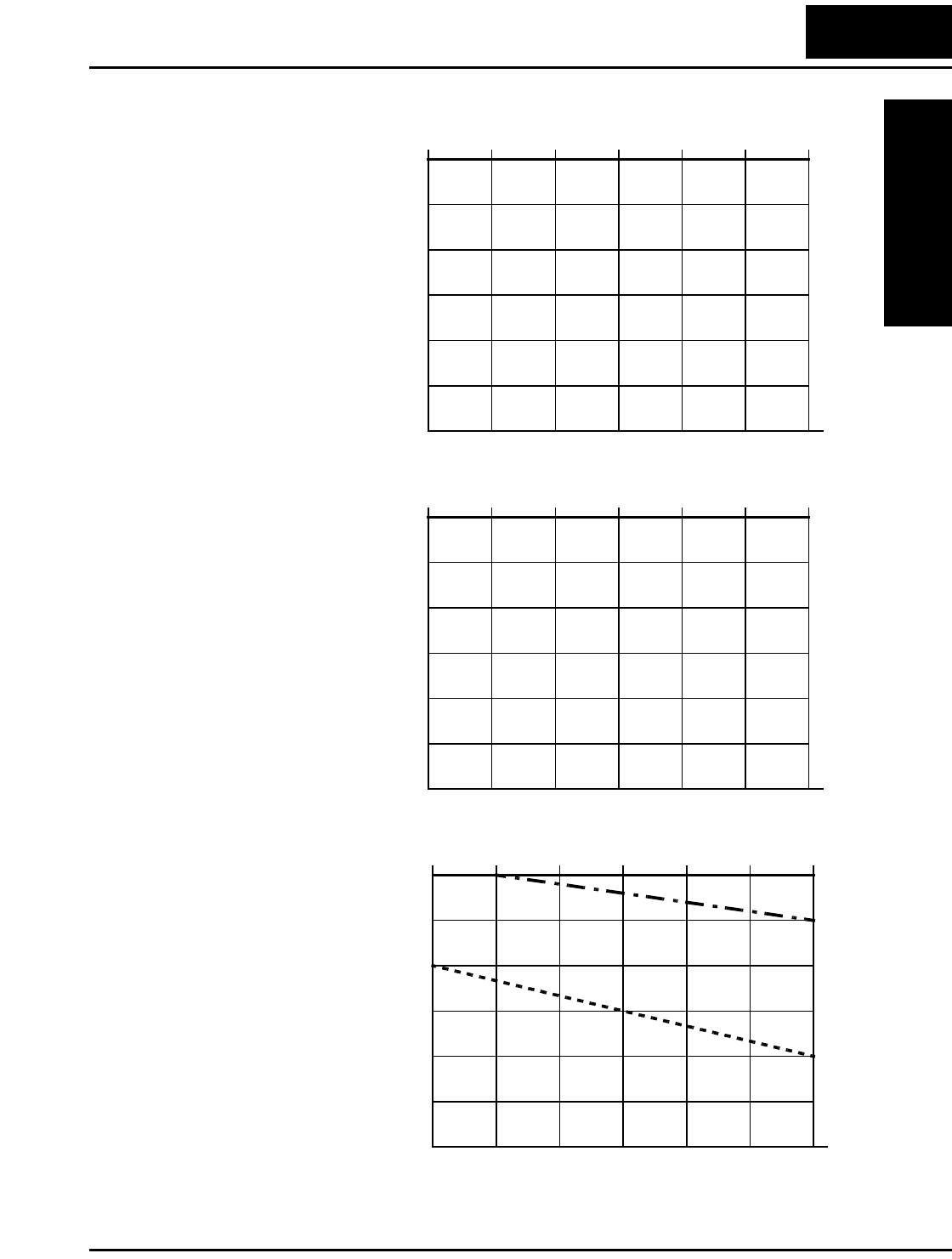
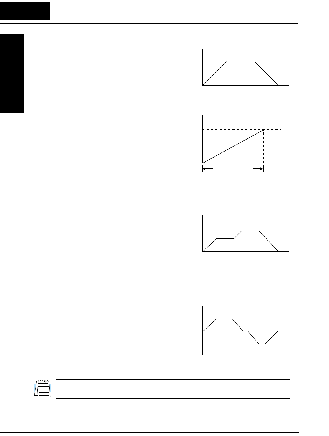
Velocity Profiles
The L2002 inverter is capable of sophisticated
speed control. A graphical representation of
that capability will help you understand and
configure the associated parameters. This
manual makes use of the velocity profile
graph used in industry (shown at right). In the
example, acceleration is a ramp to a set speed,
and deceleration is a decline to a stop.
Acceleration and deceleration settings specify
the time required to go from a stop to
maximum frequency (or visa versa). The
resulting slope (speed change divided by time)
is the acceleration or deceleration. An increase
in output frequency uses the acceleration
slope, while a decrease uses the deceleration
slope. The accel or decel time a particular
speed change depends on the starting and
ending frequencies. However, the slope is constant, corresponding to the full-scale accel
or decel time setting. For example, the full-scale acceleration setting (time) may be 10
seconds—the time required to go from 0 to 60 Hz.
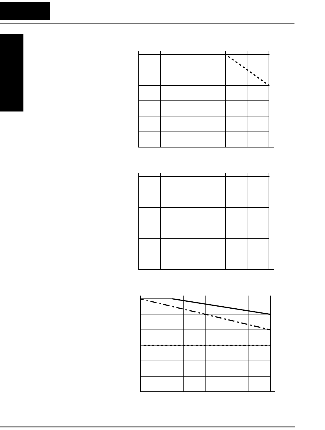
The L2002 inverter can store up to 16 preset
speeds. And, it can apply separate acceleration
and deceleration transitions from any preset to
any other preset speed. A multi-speed profile
(shown at right) uses two or more preset
speeds, which you can select via intelligent
input terminals. This external control can
apply any preset speed at any time. Alterna-
tively, the selected speed is infinitely variable across the speed range. You can use the
potentiometer control on the keypad for manual control. The drive accepts analog 0-10V
signals and 4-20 mA control signals as well.
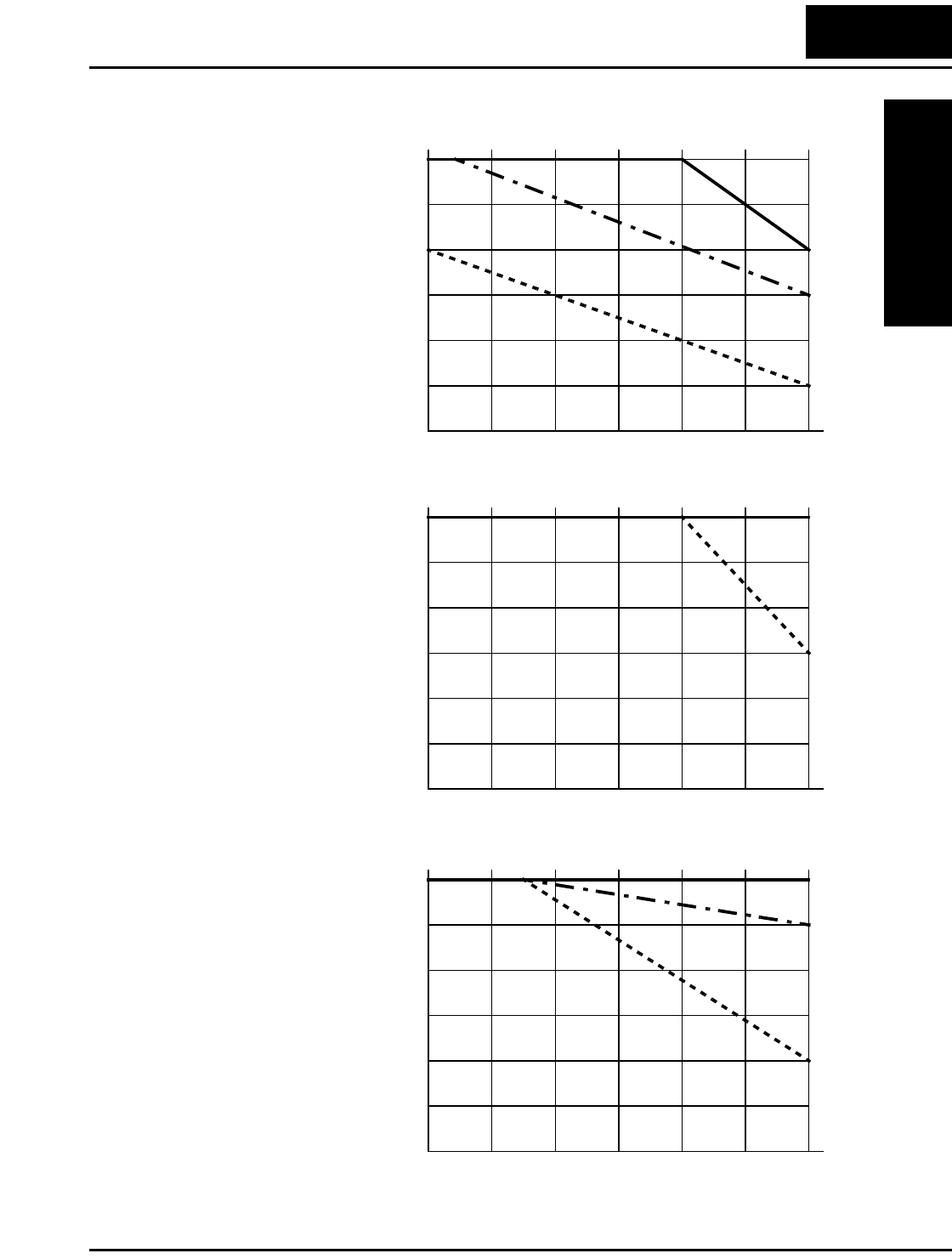
The inverter can drive the motor in either
direction. Separate FW and RV commands
select the direction of rotation. The motion
profile example shows a forward motion
followed by a reverse motion of shorter
duration. The speed presets and analog signals
control the magnitude of the speed, while the
FWD and REV commands determine the
direction before the motion starts.
NOTE: The L2002 can move loads in both directions. However, it is not designed for
use in servo-type applications that use a bipolar velocity signal that determines direction.
Velocity Profile
Speed
t
Set speed
Accel Decel
0
t
Speed Maximum speed
Acceleration
(time setting)
0
Multi-speed Profile
Speed
t
Speed 1
Speed 2
0
Bi-directional Profile
0
Speed
t
Forward move
Reverse move

L2002 Inverter
Getting Started
1–23
Frequently Asked Questions
Q. What is the main advantage in using an inverter to drive a motor, compared to
alternative solutions?
A. An inverter can vary the motor speed with very little loss of efficiency, unlike
mechanical or hydraulic speed control solutions. The resulting energy
savings usually pays for the inverter in a relatively short time.
Q. The term “inverter” is a little confusing, since we also use “drive” and “amplifier”
to describe the electronic unit that controls a motor. What does “inverter” mean?
A. The terms inverter, drive, and amplifier are used somewhat interchangeably
in industry. Nowadays, the terms drive, variable-frequency drive, variable-
speed drive, and inverter are generally used to describe electronic, micropro-
cessor-based motor speed controllers. In the past, variable-speed drive also
referred to various mechanical means to vary speed. Amplifier is a term
almost exclusively used to describe drives for servo or stepper motors.
Q. Although the L2002 inverter is a variable speed drive, can I use it in a fixed-speed
application?
A. Yes, sometimes an inverter can be used simply as a “soft-start” device,
providing controlled acceleration and deceleration to a fixed speed. Other
functions of the L2002 may be useful in such applications, as well. However,
using a variable speed drive can benefit many types of industrial and
commercial motor applications, by providing controlled acceleration and
deceleration, high torque at low speeds, and energy savings over alternative
solutions.
Q. Can I use an inverter and AC induction motor in a positioning application?
A. That depends on the required precision, and the slowest speed the motor will
must turn and still deliver torque. The L2002 inverter will deliver full torque
while turning the motor at only 0.5 Hz (15 RPM). DO NOT use an inverter if
you need the motor to stop and hold the load position without the aid of a
mechanical brake (use a servo or stepper motion control system).
Q. Can the inverter be controlled and monitored via a network?
A. Yes. L2002 inverters have built-in ModBus communications. See
Appendix B for more information on network communications.
Q. Why does the manual or other documentation use terminology such as “200V
class” instead of naming the actual voltage, such as “230 VAC?”
A. A specific inverter model is set at the factory to work across a voltage range
particular to the destination country for that model. The model specifications
are on the label on the side of the inverter. A European 200V class inverter
(“EU” marking) has different parameter settings than a USA 200V class
inverter (“US” marking). The initialization procedure (see “Restoring
Factory Default Settings” on page 6–8) can set up the inverter for European
or US commercial voltage ranges.

Frequently Asked Questions
Getting Started
1–24
Q. Why doesn’t the motor have a neutral connection as a return to the inverter?
A. The motor theoretically represents a “balanced Y” load if all three stator
windings have the same impedance. The Y connection allows each of the
three wires to alternately serve as input or return on alternate half-cycles.
Q. Does the motor need a chassis ground connection?
A. Yes, for several reasons. Most importantly, this provides protection in the
event of a short in the motor that puts a hazardous voltage on its housing.
Secondly, motors exhibit leakage currents that increase with aging. Lastly, a
grounded chassis generally emits less electrical noise than an ungrounded
one.
Q. What type of motor is compatible with the Hitachi inverters?
A. Motor type – It must be a three-phase AC induction motor. Use an inverter-
grade motor that has 800V insulation for 200V class inverters, or 1600V
insulation for 400V class.
Motor size – In practice, it’s better to find the right size motor for your
application; then look for the inverter to match the motor.
NOTE: There may be other factors that will affect motor selection, including heat dissi-
pation, motor operating speed profile, enclosure type, and cooling method.
Q. How many poles should the motor have?
A. Hitachi inverters can be configured to operate motors with 2, 4, 6, or 8 poles.
The greater the number of poles, the slower the top motor speed will be, but
it will have higher torque at the base speed.
Q. Will I be able to add dynamic (resistive) braking to my Hitachi L2002 drive after
the initial installation?
A. Yes. You can connect a dynamic braking unit to the L2002 inverter. The
resistor in the braking unit must be sized to meet the braking requirements.
More information on dynamic braking is located in Chapter 5.

L2002 Inverter
Getting Started
1–25
Q. How will I know if my application will require resistive braking?
A. For new applications, it may be difficult to tell before you actually test a
motor/drive solution. In general, some applications can rely on system losses
such as friction to serve as the decelerating force, or otherwise can tolerate a
long decel time. These applications will not need dynamic braking.
However, applications with a combination of a high-inertia load and a
required short decel time will need dynamic braking. This is a physics
question that may be answered either empirically or through extensive calcu-
lations.
Q. Several options related to electrical noise suppression are available for the Hitachi
inverters. How can I know if my application will require any of these options?
A. The purpose of these noise filters is to reduce the inverter electrical noise so
the operation of nearby electrical devices is not affected. Some applications
are governed by particular regulatory agencies, and noise suppression is
mandatory. In those cases, the inverter must have the corresponding noise
filter installed. Other applications may not need noise suppression, unless
you notice electrical interference with the operation of other devices.
Q. The L2002 features a PID loop feature. PID loops are usually associated with
chemical processes, heating, or process industries in general. How could the PID
loop feature be useful in my application?
A. You will need to determine the particular main variable in your application
the motor affects. That is the process variable (PV) for the motor. Over time,
a faster motor speed will cause a faster change in the PV than a slow motor
speed will. By using the PID loop feature, the inverter commands the motor
to run at the optimal speed required to maintain the PV at the desired value
for current conditions. Using the PID loop feature will require an additional
sensor and other wiring, and is considered an advanced application.


Inverter Mounting
and Installation
In This Chapter.... page
— Orientation to Inverter Features ...................... 2
— Basic System Description ............................... 7
— Step-by-Step Basic Installation........................ 8
— Powerup Test ................................................ 22
— Using the Front Panel Keypad ...................... 24
2
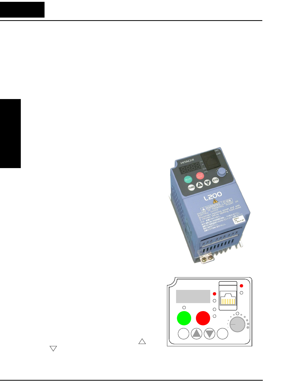
Orientation to Inverter Features
Inverter Mounting
and Installation
2–2
Orientation to Inverter Features
Unpacking and Inspection
Please take a few moments to unpack your new L2002 inverter and perform these steps:
1. Look for any damage that may have occurred during shipping.
2. Verify the contents of the box include:
a. One L2002 inverter
b. One Instruction Manual
c. One L2002 Quick Reference Guide
3. Inspect the specifications label on the side of the inverter. Make sure it matches the
product part number you ordered.
Main Physical Features
The L2002 Series inverters vary in size accord-
ing to the current output rating and motor size
for each model number. All feature the same
basic keypad and connector interface for consis-
tent ease of use. The inverter construction has a
heat sink at the back of the housing. The larger
models include a fan(s) to enhance heat sink
performance. The mounting holes are pre-
drilled in the heat sink for your convenience.
Smaller models have two mounting holes, while
larger ones have four. Be sure to use all the
mounting holes provided.
Two chassis GND screws are located on the
metal tab on the heat sink at the bottom of the
inverter. Never touch the heat sink during or just
after operation; it can be very hot.
The electronics housing and front panel are built
onto the front of the heat sink.
Inverter Keypad - The inverter uses a digital
operator interface, or keypad. The four-digit
display can show a variety of performance
parameters. LEDs indicate whether the display
units are Hertz or Amperes. Other LEDs
indicate Power (external), and Run/Stop Mode
and Program/Monitor Mode status. Membrane
keys Run and Stop/Reset, and an output
frequency potentiometer (speed setting knob)
control motor operation. The FUNC., , and
keys allow an operator to navigate to the
inverter’s functions and parameter values. The
Store key is used when changing a setting.
12
RUN STOP
RESET
FUNC.
STR
HITACHI
POWER
ALARM
RUN
A
Hz
PRG
5 0.0
1
2
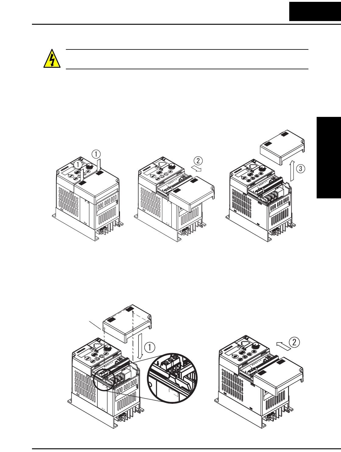
L2002 Inverter
Inverter Mounting
and Installation
2–3
Front Housing Cover
HIGH VOLTAGE: Hazard of electrical shock. Disconnect incoming power before
working on this control. Wait five (5) minutes before removing the front cover.
To remove the cover, follow the steps below (applies to all inverter models):
1. Press downward on the cover at the two areas indicated to release the retaining tabs.
2. Slide the cover forward and away from the keypad until the top edge of the cover
reaches the notch in the inverter chassis.
3. Lift the cover upward to remove it.
To install the cover, follow the steps below (applies to all inverter models):
1. Align the tabs on the front housing cover with the notch on each edge of the inverter
chassis. Then lower the cover into position.
2. Slide the cover toward the keypad, keeping it flush against the inverter chassis.
Continue until the cover latches into place.
Notch on
inverter chassis
Tab
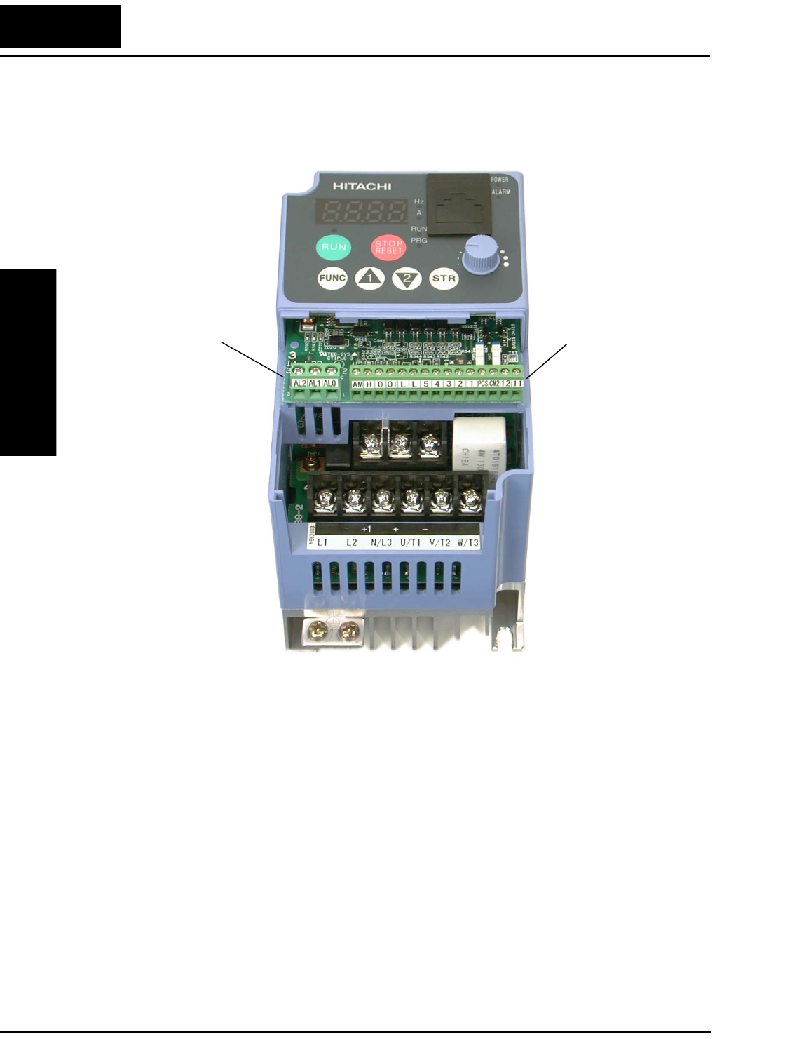
Orientation to Inverter Features
Inverter Mounting
and Installation
2–4
Logic Connector Introduction
After removing the front housing cover, take a moment to become familiar with the
connectors, as shown below.
Logic and analog
signal connections
Relay output
contacts
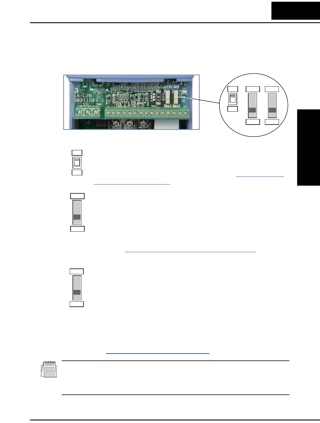
L2002 Inverter
Inverter Mounting
and Installation
2–5
DIP Switch Introduction
The inverter has three (3) internal DIP switches, located to the right of the logic connec-
tors as shown below. This section provides an introduction, and refers you to other
chapters that discuss each DIP switch in depth.
The SR/SK (Source/Sink) DIP switch configures the inverter’s intelligent
inputs for sinking or sourcing type circuit. Note that the installation and
Powerup Test steps in this chapter do not require wiring the input terminals.
The SR/SK switch configuration is covered in detail in “Using Intelligent
Input Terminals” on page 4–9.
The 485/OPE (RS-485/Operator) DIP switch configures the inverter’s RS-
485 serial port. You can use the inverter’s keypad (OPE-SRmini) either on
the inverter, or connected via a cable to the serial port. For the keypad, either
position of the 485/OPE DIP switch will work. However, communication
with “smart” operator devices requires the proper setting. Using digital
operators (such as OPE–SR or OPE–0EX requires the “OPE” setting.
Inverter control via a ModBus network communication requires the “485”
setting. See “Connecting the Inverter to ModBus” on page B–3 for more
details.
The TM/PRG (Terminal/Program) DIP switch affects the inverter’s setting
for control sources. Parameter A001 sets the source selection for the
inverter’s output frequency (motor speed). Parameter A002 selects the Run
command source (for FW and RV). These independently select among
sources such as input terminals, inverter keypad keys and potentiometer,
internal register settings, ModBus network, etc.
When the TM/PRG switch is set to PRG, parameter settings A001 and A002
are in effect. However, when the switch is in the TM (terminal) position, the
inverter uses the analog input terminals for the motor speed setting, and uses
the [FW] and/or [REV] terminals for the Run command. More information
is in “Control Source Settings” on page 3–10.
NOTE: L2002 inverters have built-in ModBus RTU RS-485 communications. Connect-
ing to other networks such as DeviceNet, Ethernet, CANopen, and ProfiBus is possible
by adding optional, external interface devices. Contact your Hitachi distributor for more
information.
SR
SK
OPE
485
PRG
TM
SR
SK
OPE
485
PRG
TM
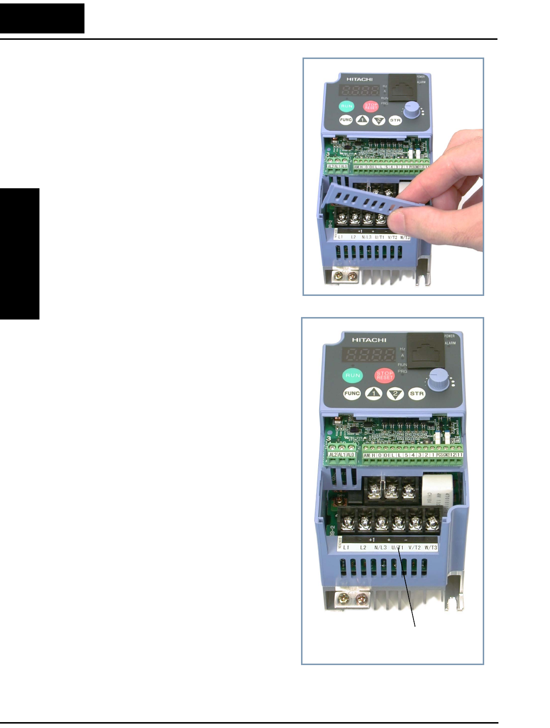
Orientation to Inverter Features
Inverter Mounting
and Installation
2–6
Power Wiring Access - First, ensure no
power source of any kind is connected to the
inverter. If power has been connected, wait
five minutes after powerdown and verify the
Power LED is OFF to proceed. After
removing the front housing cover, the housing
partition that covers the power wiring exit will
be able to slide upward as shown to the right.
Notice the four wire exit slots (on larger
model inverters) in the housing partition. This
helps keep the power wiring (to the left)
separate from signal-level logic or analog
wiring (to the right).
Remove the housing partition and as shown as
set it aside in a secure place while wiring.
Never operate the inverter drive with the parti-
tion removed or the front housing cover
removed.
The power input and motor 3-phase wiring
connect to the lower row of terminals. The
upper row of power terminals connect to
optional dynamic braking components.
The following sections in this chapter will
describe the system design and guide you
through a step-by-step installation process.
After the section on wiring, this chapter will
show how to use the front panel keys to
access functions and edit parameters.
Power and motor
connection terminals
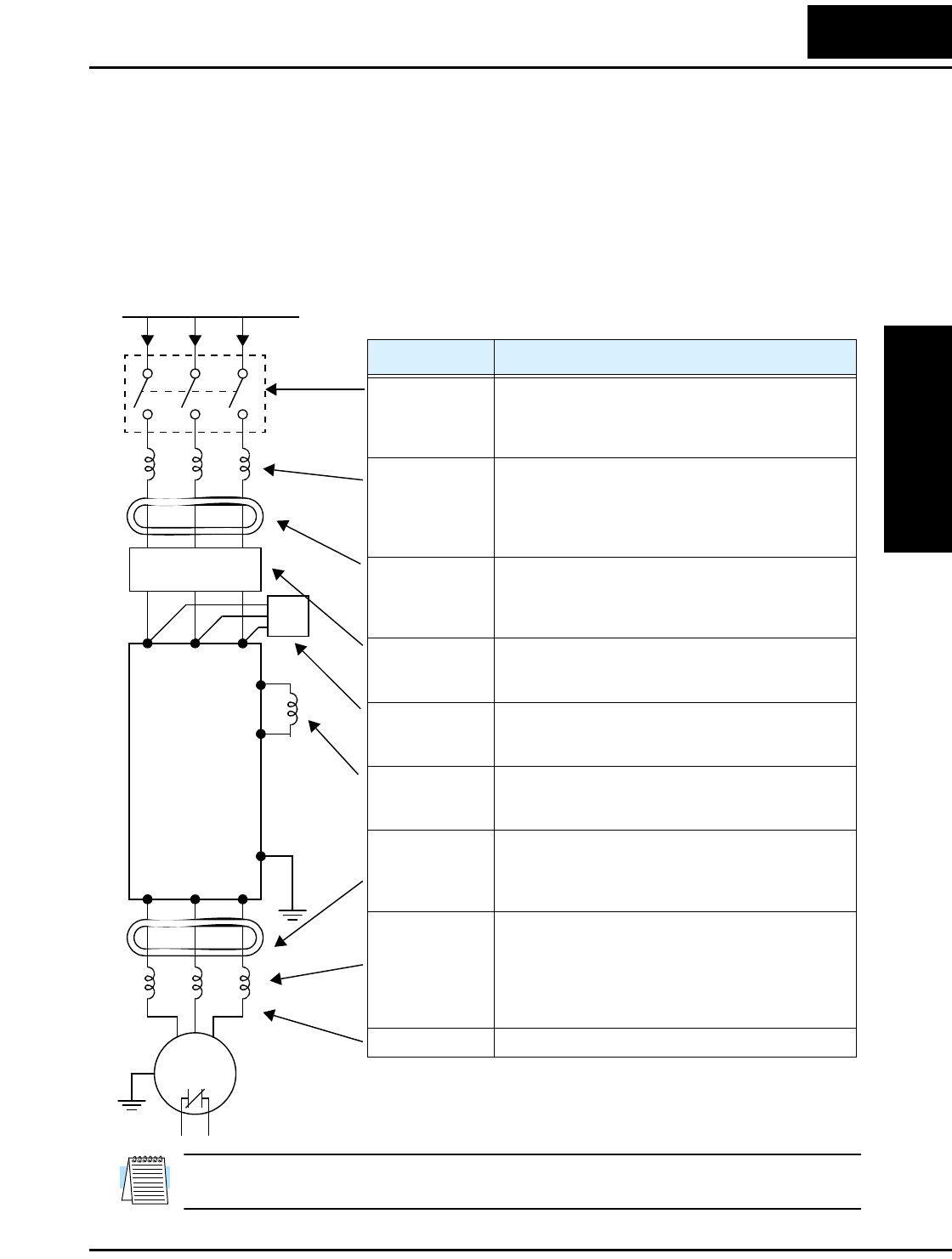
L2002 Inverter
Inverter Mounting
and Installation
2–7
Basic System Description
A motor control system will obviously include a motor and inverter, as well as a breaker
or fuses for safety. If you are connecting a motor to the inverter on a test bench just to get
started, that’s all you may need for now. But a system can also have a variety of
additional components. Some can be for noise suppression, while others may enhance
the inverter’s braking performance. The figure and table below show a system with all
the optional components you may need in your finished application.
NOTE: Note that some components are required for regulatory agency compliance (see
Chapter 5 and Appendix D).
Thermal
switch
Breaker,
MCCB or
GFI
From power supply
Motor
L1 L2 L3
+1
+
Inverter
GND
T1 T2 T3
Name Function
Breaker /
disconnect
A molded-case circuit breaker (MCCB), ground fault
interrupter (GFI), or a fused disconnect device. NOTE:
The installer must refer to the NEC and local codes to
ensure safety and compliance.
Input-side
AC Reactor
This is useful in suppressing harmonics induced on the
power supply lines and for improving the power factor.
WARNING: Some applications must use an input-
side AC reactor to prevent inverter damage. See
Warning on next page.
Radio noise filter Electrical noise interference may occur on nearby
equipment such as a radio receiver. This magnetic
choke filter helps reduce radiated noise (can also be
used on output).
EMI filter (for
CE applications,
see Appendix D)
Reduces the conducted noise on the power supply
wiring between the inverter and the power distribution
system. Connect to the inverter primary (input side).
Radio noise filter
(use in non-CE
applications)
This capacitive filter reduces radiated noise from the
main power wires in the inverter input side.
DC link choke Suppresses harmonics generated by the inverter.
However, it will not protect the input diode bridge
rectifier.
Radio noise filter Electrical noise interference may occur on nearby
equipment such as a radio receiver. This magnetic
choke filter helps reduce radiated noise (can also be
used on input).
Output-side
AC reactor
This reactor reduces the vibrations in the motor caused
by the inverter’s switching waveforms, by smoothing
the waveform to approximate commercial power
quality. It is also useful to reduce harmonics when
wiring from the inverter to the motor is more than 10m
in length.
LCR filter Sine wave shaping filter for output side.
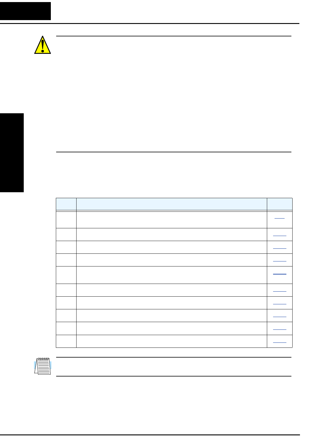
Step-by-Step Basic Installation
Inverter Mounting
and Installation
2–8
WARNING: In the cases below involving a general-purpose inverter, a large peak
current can flow on the power supply side, sometimes destroying the converter module:
1.The unbalance factor of the power supply is 3% or higher.
2.The power supply capacity is at least 10 times greater than the inverter capacity
(or the power supply capacity is 500 kVA or more).
3.Abrupt power supply changes are expected, due to conditions such as:
a. Several inverters are interconnected with a short bus.
b. A thyristor converter and an inverter are interconnected with a short bus.
c. An installed phase advance capacitor opens and closes.
Where these conditions exist or when the connected equipment must be highly reliable,
you MUST install an input-side AC reactor of 3% (at a voltage drop at rated current)
with respect to the supply voltage on the power supply side. Also, where the effects of an
indirect lightning strike are possible, install a lightning conductor.
Step-by-Step Basic Installation
This section will guide you through the following basic steps of installation:
NOTE: If the installation is in an EU country, study the EMC installation guidelines in
Appendix D.
Step Activity Page
1Choose a mounting location in compliance with the Warnings and Cautions.
See NOTE below.
2–9
2Check the mounting location for adequate ventilation. 2–10
3Cover the inverter’s ventilation openings to prevent debris from entering. 2–10
4Check the inverter dimensions for footprint and mounting hole locations. 2–11
5Study the Cautions, Warnings, wire and fuse sizes, and terminal torque
specifications before wiring the inverter.
2–16
6Connect wiring for the inverter power input. 2–18
7Wire the inverter output to the motor. 2–21
8Uncover the inverter’s ventilation openings applied in Step 3. 2–22
9Perform the Powerup Test. (This step includes several substeps.) 2–22
10 Make observations and check your installation. 2–33
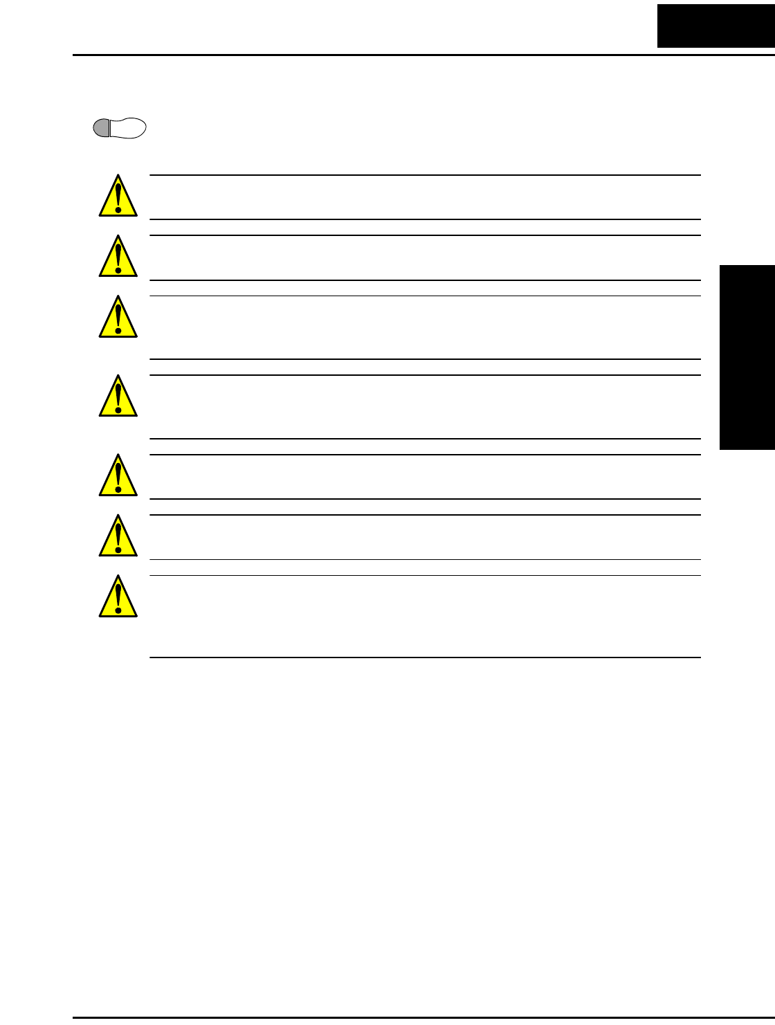
L2002 Inverter
Inverter Mounting
and Installation
2–9
Choosing a Mounting Location
Step 1: Study the following caution messages associated with mounting the inverter.
This is the time when mistakes are most likely to occur that will result in expensive
rework, equipment damage, or personal injury.
CAUTION: Be sure to install the unit on flame-resistant material such as a steel plate.
Otherwise, there is the danger of fire.
CAUTION: Be sure not to place any flammable materials near the inverter. Otherwise,
there is the danger of fire.
CAUTION: Be sure not to let the foreign matter enter vent openings in the inverter
housing, such as wire clippings, spatter from welding, metal shavings, dust, etc. Other-
wise, there is the danger of fire.
CAUTION: Be sure to install the inverter in a place that can bear the weight according
to the specifications in the text (Chapter 1, Specifications Tables). Otherwise, it may fall
and cause injury to personnel.
CAUTION: Be sure to install the unit on a perpendicular wall that is not subject to
vibration. Otherwise, it may fall and cause injury to personnel.
CAUTION: Be sure not to install or operate an inverter that is damaged or has missing
parts. Otherwise, it may cause injury to personnel.
CAUTION: Be sure to install the inverter in a well-ventilated room that does not have
direct exposure to sunlight, a tendency for high temperature, high humidity or dew
condensation, high levels of dust, corrosive gas, explosive gas, inflammable gas,
grinding-fluid mist, salt damage, etc. Otherwise, there is the danger of fire.
1
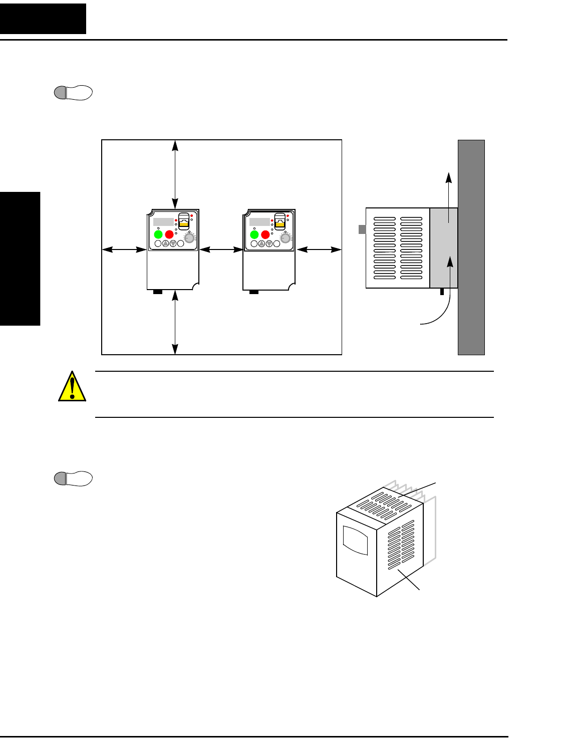
Step-by-Step Basic Installation
Inverter Mounting
and Installation
2–10
Ensure Adequate Ventilation
Step 2: To summarize the caution messages—you will need to find a solid, non-flamma-
ble, vertical surface that is in a relatively clean and dry environment. In order to ensure
enough room for air circulation around the inverter to aid in cooling, maintain the speci-
fied clearance around the inverter specified in the diagram.
CAUTION: Be sure to maintain the specified clearance area around the inverter and to
provide adequate ventilation. Otherwise, the inverter may overheat and cause equipment
damage or fire.
Keep Debris Out of Inverter Vents
Step 3: Before proceeding to the wiring section, it’s
a good time to temporarily cover the inverter’s
ventilation openings. Paper and masking tape are
all that is needed. This will prevent harmful debris
such as wire clippings and metal shavings from
entering the inverter during installation.
Please observe this checklist while mounting the
inverter:
1. The ambient temperature must be in the range of
–10 to 40°C.
2. Keep any other heat-producing equipment as far
away from the inverter as possible.
3. When installing the inverter in an enclosure, maintain the clearance around the
inverter and verify that its ambient temperature is within specification when the
enclosure door is closed.
4. Do not remove the front housing cover at any time during operation.
2
10 cm (3.94”)
minimum
10 cm (3.94”)
minimum
Clear area
Air flow
L2002
12
RUN STOP
RESET
FUNC.
STR
HITACHI
POWER
ALARM
RUN
A
Hz
PRG
5 0.0
2 cm
(0.79”)
min.
2 cm
(0.79”)
min.
2 cm
(0.79”)
min.
L2002
12
RUN STOP
RESET
FUNC.
STR
HITACHI
POWER
ALARM
RUN
A
Hz
PRG
5 0.0
3
Ventilation holes
(both sides)
Ventilation holes
(top)
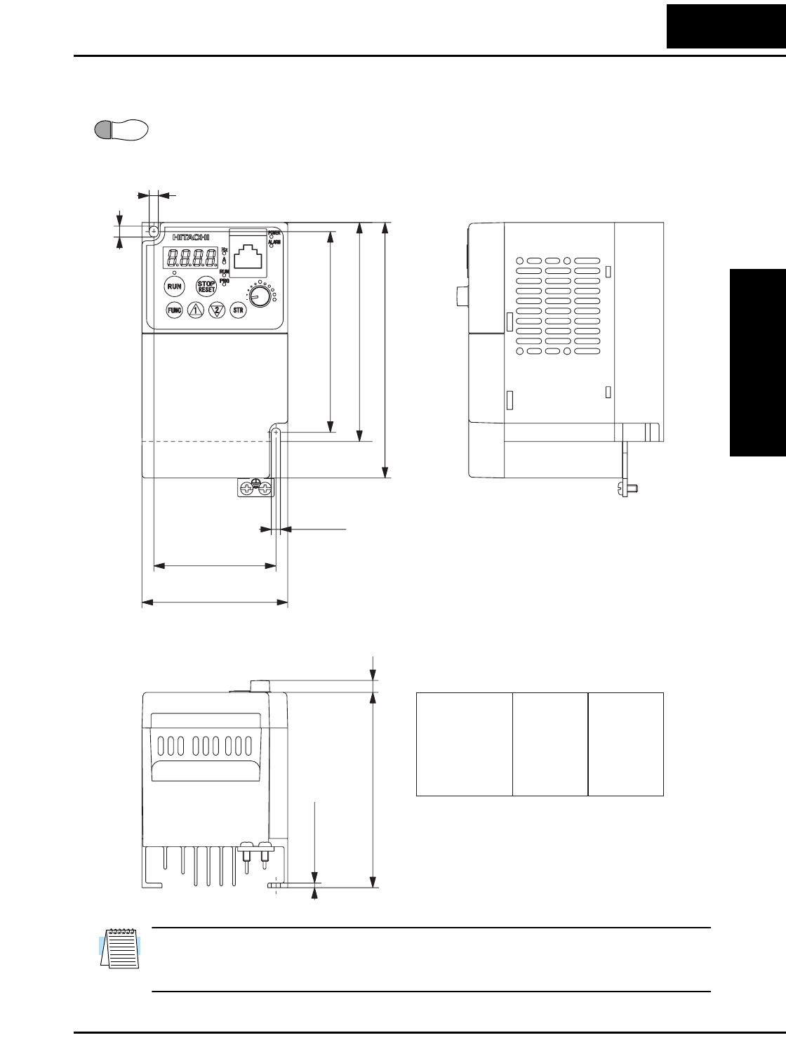
L2002 Inverter
Inverter Mounting
and Installation
2–11
Check Inverter Dimensions
Step 4: Locate the applicable drawing on the following pages for your inverter.
Dimensions are given in millimeters (inches) format.
NOTE: Some inverter housings require two mounting screws, while others require four.
Be sure to use lock washers or other means to ensure screws do not loosen due to
vibration.
4
5(0.20)
6(0.24)
110(4.48)
H=120(4.90)
H=140(5.51)
2.6(0.102)
D=107(4.21)
D=130(5.12)
93(3.66)
93(3.66)
107(4.21)
107(4.21)
130(5.12)
120(4.90)
140(5.51)
120(4.90)
140(5.51)
140(5.51)
-002NFU
-002NFEF2
-004NFU2
-004NFEF2
-005NFEF2
HModel D
67(2.64)
80(3.15)
5(0.20)
7(0.16)
D=93(3.66)
2
L200–002NFU2, -002NFEF2, –004NFU2, -004NFEF2, –005NFEF2

Step-by-Step Basic Installation
Inverter Mounting
and Installation
2–12
Dimensional drawings, continued...
2-φ5(0.20)
118(4.64)
H=130(5.130)
H=155(6.10)
130(5.130)
155(6.10)
155(6.10)
-004HFU2
-004HFEF2
-007NFEF2
HModel
98(3.86)
110(4.33)
7(0.16)
5(0.20)
6(0.24)
129(5.08)
L200–004HFU2, –004HFEF2, –007NFEF2
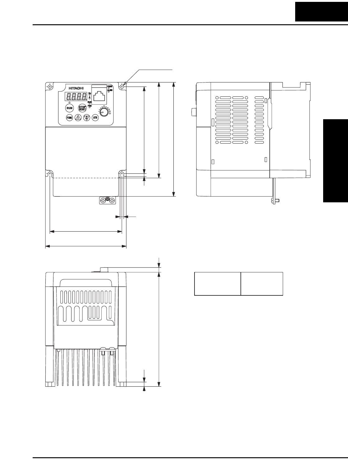
L2002 Inverter
Inverter Mounting
and Installation
2–13
Dimensional drawings, continued...
2-φ5(0.20)
118(4.64)
H=130(5.130)
H=155(6.10)
130(5.130)
155(6.10)
HModel
98(3.86)
110(4.33)
7(0.16)
5(0.20)
6(0.24)
129(5.08)
4(0.16)
-007HFU2
-007HFEF2
L200–007HFU2, –007HFEF2
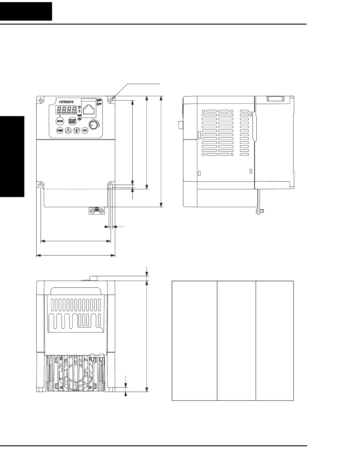
Step-by-Step Basic Installation
Inverter Mounting
and Installation
2–14
Dimensional drawings, continued...
2-φ5(0.20)
118(4.64)
H=130(5.130)
H=155(6.10)
130(5.12)
130(5.12)
130(5.12)
130(5.12)
130(5.12)
130(5.12)
130(5.12)
155(6.10)
155(6.10)
155(6.10)
155(6.10)
155(6.10)
155(6.10)
155(6.10)
-007NFU2
-015NFU2
-015HFU2
-022NFU2
-022HFU2
-037LFU2
-040HFU2
-011NFEF2
-015NFEF2
-015HFEF2
-022NFEF2
-022HFEF2
-030HFEF2
-040HFEF2
HModel
98(3.86)
110(4.33)
7(0.16)
5(0.20)
6(0.24) D=129(5.08)
D=156(6.14)
D
129(5.08)
156(6.14)
156(6.14)
156(6.14)
156(6.14)
156(6.14)
156(6.14)
155(6.10)
155(6.10)
155(6.10)
155(6.10)
155(6.10)
155(6.10)
155(6.10)
L200–007NU2, -015NFU2, 015HFU2,-022NFU2, -022HFU2, -037LFU2, -040HFU2, -
011NFEF2, -015NFEF2, -015HFEF2, -022NFEF2, -022HFEF2, -030HFEF2, -040HFEF2
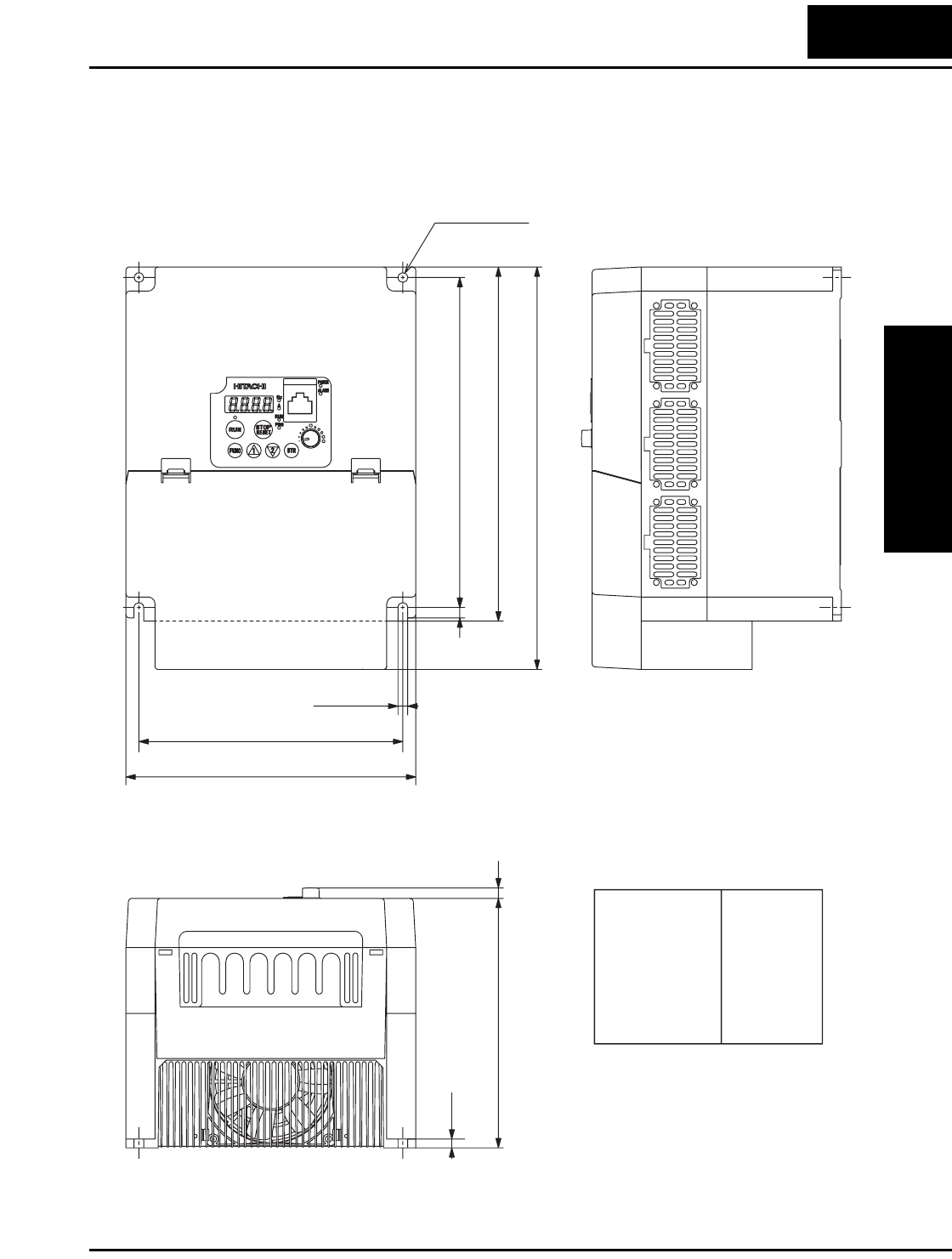
L2002 Inverter
Inverter Mounting
and Installation
2–15
Dimensional drawings, continued...
2-φ5(0.20)
205(8.07)
H=220(8.66)
H=250(9.84)
205(8.07)
205(8.07)
205(8.07)
205(8.07)
250(9.84)
250(9.84)
-055LFU2
-055HFU2
-075LFU2
-075HFU2
-055HFEF2
-075HFEF2
HModel
164(6.46)
180(7.09)
7(0.16)
6.5(0.25)
6(0.24)
5.5(0.22)
155(6.10)
6(0.24)
L200–055LFU2, –055HFU2, –075LFU2, -075HFU2, –055HFEF2, -075HFEF2
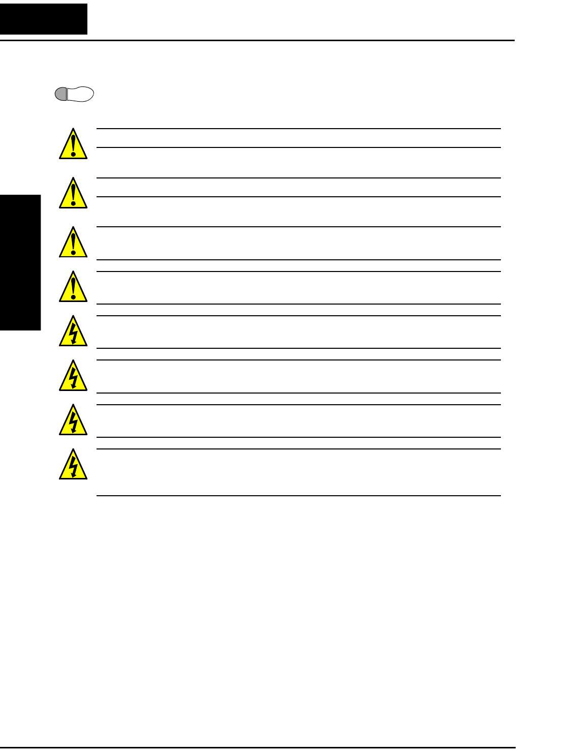
Step-by-Step Basic Installation
Inverter Mounting
and Installation
2–16
Prepare for Wiring
Step 5: It is very important to perform the wiring steps carefully and correctly. Before
proceeding, please study the caution and warning messages below.
WARNING: “Use 60/75°C Cu wire only” or equivalent.
WARNING: “Open Type Equipment.”
WARNING: “Suitable for use on a circuit capable of delivering not more than 100,000
rms symmetrical amperes, 240 V maximum.” For models with suffix N or L.
WARNING: “Suitable for use on a circuit capable of delivering not more than 100,000
rms symmetrical amperes, 480 V maximum.” For models with suffix H.
HIGH VOLTAGE: Be sure to ground the unit. Otherwise, there is a danger of electric
shock and/or fire.
HIGH VOLTAGE: Wiring work shall be carried out only by qualified personnel. Other-
wise, there is a danger of electric shock and/or fire.
HIGH VOLTAGE: Implement wiring after checking that the power supply is OFF. Oth-
erwise, you may incur electric shock and/or fire.
HIGH VOLTAGE: Do not connect wiring to an inverter or operate an inverter that is
not mounted according the instructions given in this manual. Otherwise, there is a danger
of electric shock and/or injury to personnel.
5
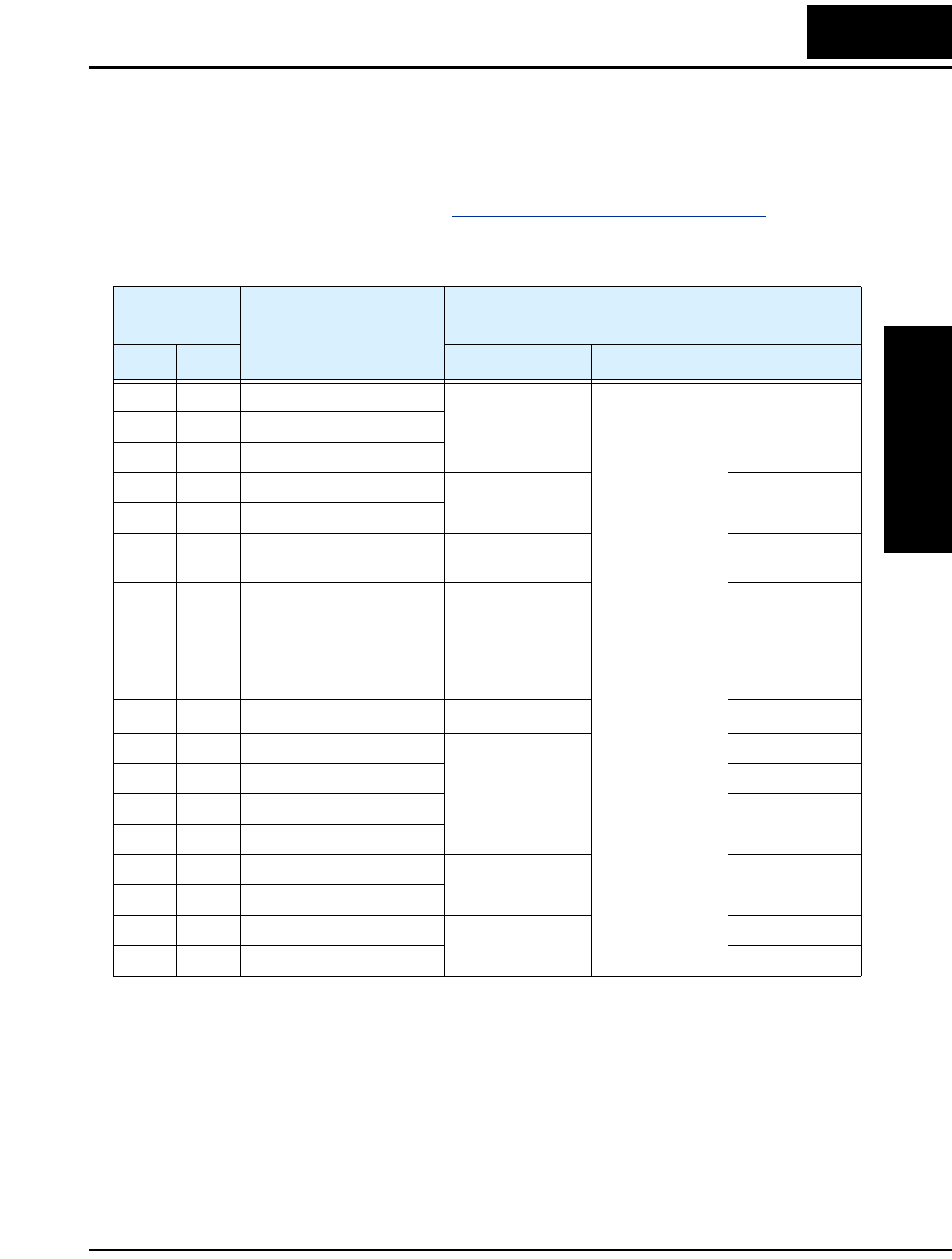
L2002 Inverter
Inverter Mounting
and Installation
2–17
Determining Wire and Fuse Sizes
The maximum motor currents in your application determines the recommended wire
size. The following table gives the wire size in AWG. The “Power Lines” column applies
to the inverter input power, output wires to the motor, the earth ground connection, and
any other component shown in the “Basic System Description” on page 2–7. The
“Signal Lines” column applies to any wire connecting to the two green 8-position
connectors just inside the front panel half-door.
Note 1: Field wiring must be made by a UL-listed and CSA-certified closed-loop
terminal connector sized for the wire gauge involved. Connector must be
fixed by using the crimping tool specified by the connector manufacturer.
Note 2: Be sure to consider the capacity of the circuit breaker to be used.
Note 3: Be sure to use a larger wire gauge if power line length exceeds 66 ft. (20m).
Note 4: Use 18 AWG / 0.75 mm2 wire for the alarm signal wire ([AL0], [AL1], [AL2]
terminals).
Note 5: The inverter’s input power wiring must include UL Listed, dual-element,
600V fuses, or UL Listed, inverse-time, 600V circuit breakers.
Motor Output
(kW/HP) Inverter Model
Wiring Applicable
equipment
kW HP Power Lines Signal Lines Fuse / Breaker
0.2 1/4 L200-002NFE(F)2/NFU2
AWG16 / 1.3 mm2
18 to 28 AWG /
0.14 to 0.75 mm2
shielded wire
(see Note 4)
10A0.4 1/2 L200-004NFE(F)2/NFU2
0.55 3/4 L200-005NFE(F)2
0.75 1 L200-007NFE(F)2/NFU2
AWG14 / 2.1 mm215A
1.1 1 1/2 L200-011NFE(F)2
1.5 2 L200-015NFE(F)2/NFU2 AWG12 / 3.3 mm220A (single ph.)
15A (three ph.)
2.2 3 L200-022NFE(F)2/NFU2 AWG10 / 5.3 mm230A (single ph.)
20A (three ph.)
3.7 5 L200-037LFU2 AWG10 / 5.3 mm230A
5.5 7 1/2 L200-055LFU2 AWG10 / 5.3 mm240A
7.5 10 L200-075LFU2 AWG8 / 8.4 mm250A
0.4 1/2 L200-004HFE(F)2/HFU2
AWG16 / 1.3 mm2
3A
0.75 1 L200-007HFE(F)2/HFU2 6A
1.5 2 L200-015HFE(F)2/HFU2 10A
2.2 3 L200-022HFE(F)2/HFU2
3.0 4 L200-030HFE(F)2
AWG14 / 2.1 mm215A
4.0 5 L200-040HFE(F)2/HFU2
5.5 7 1/2 L200-055HFE(F)2/HFU2
AWG12 / 3.3 mm220A
7.5 10 L200-075HFE(F)2/HFU2 25A
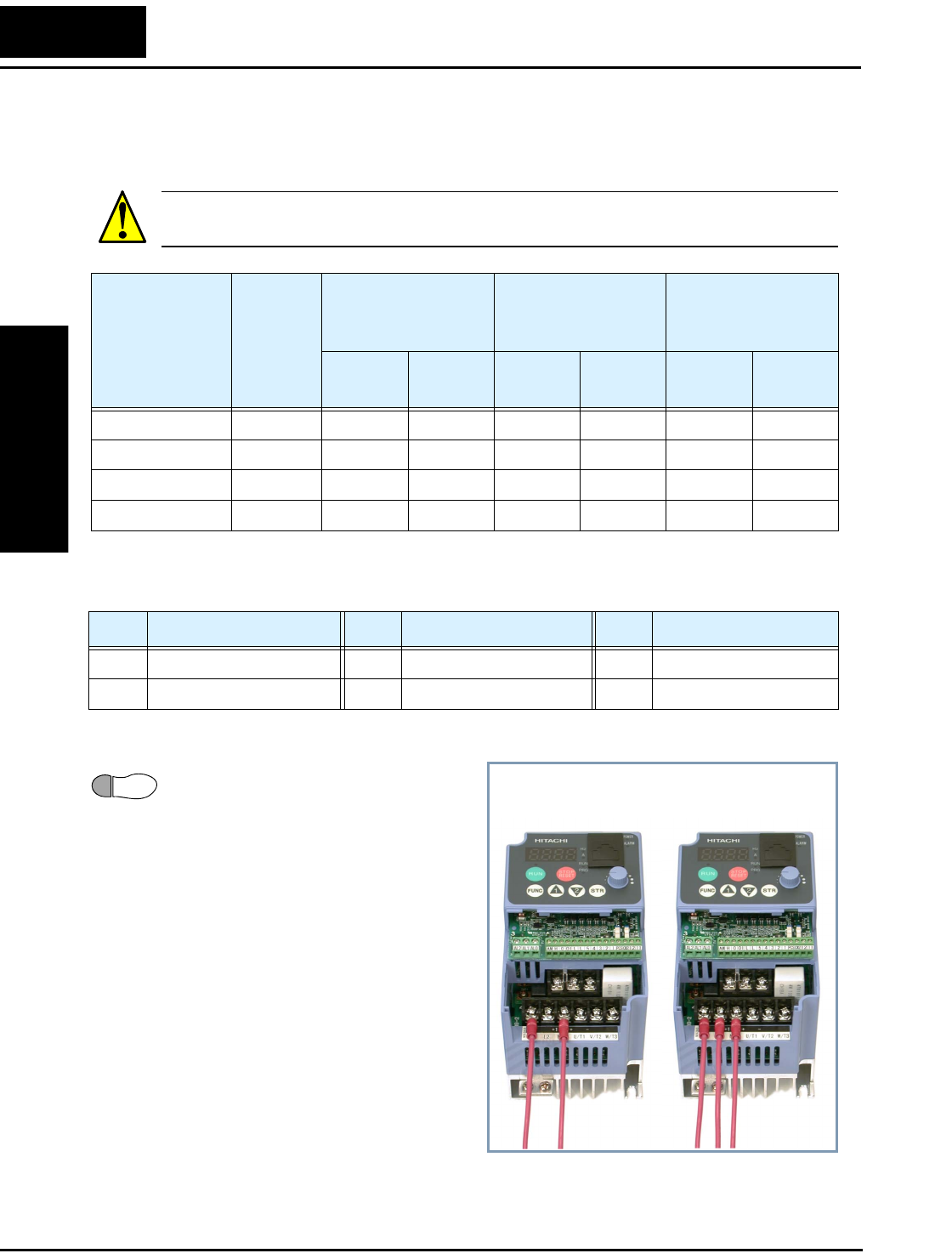
Step-by-Step Basic Installation
Inverter Mounting
and Installation
2–18
Terminal Dimensions and Torque Specs
The terminal screw dimensions for all L2002 inverters are listed in table below. This
information is useful in sizing spade lug or ring lug connectors for wire terminations.
CAUTION: Fasten the screws with the specified fastening torque in the table below.
Check for any loosening of screws. Otherwise, there is the danger of fire.
When connecting wiring, use the tightening torque listed in the following table to safely
attach wiring to the connectors.
Wire the Inverter Input to a Supply
Step 6: In this step, you will connect
wiring to the input of the inverter. First,
you must determine whether the inverter
model you have requires three-phase
power only, or if it can accept either
single-phase or three-phase power. All
models have the same power connector
terminals [R/L1], [S/L2], and [T/L3].
So, you must refer to the specifications
label (on the side of the inverter) for
the acceptable power source types! For
inverters that can accept single-phase
power and are connected that way,
terminal [S/L2] will remain uncon-
nected.
The examples to the right show single-
phase and 3-phase input wiring. Note the
use of ring lug connectors for a secure connection.
Connector
Number
of Screw
Terminals
Models 002NF,
004NF, 005NF
Models 007NF-
022NF, 037LF,
004HF - 040HF
Models 055LF,
075LF, 055HF,
075HF
Screw
Diameter
Width
(mm)
Screw
Diameter
Width
(mm)
Screw
Diameter
Width
(mm)
Power Terminals 12 M3.5 7.1 M4 9 M5 13
Control Signal 16 M2 — M2 — M2 —
Alarm Signal 3 M3—M3—M3—
Ground Terminals 2 M4 — M4 — M5 —
Screw Tightening Torque Screw Tightening Torque Screw Tightening Torque
M2 0.2 N•m (max. 0.25 N•m) M3.5 0.8 N•m (max. 0.9 N•m) M5 2.0 N•m (max. 2.2 N•m)
M3 0.5 N•m (max. 0.6 N•m) M4 1.2 N•m (max. 1.3 N•m) — —
6Single-phase
input wiring
3-phase
input wiring
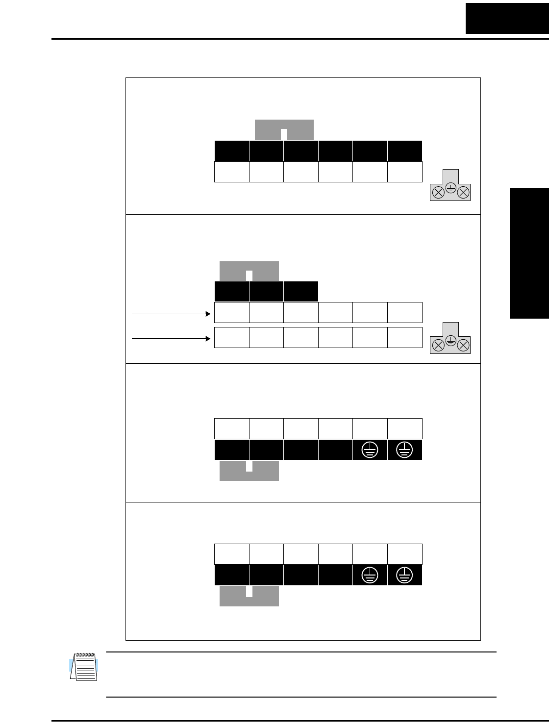
L2002 Inverter
Inverter Mounting
and Installation
2–19
Please use the terminal arrangement below corresponding to your inverter model.
NOTE: An inverter powered by a portable power generator may receive a distorted
power waveform, overheating the generator. In general, the generator capacity should be
five times that of the inverter (kVA).
Inverter models L200–002NFEF2/NFU2, –004NFEF2/NFU2,
–005NFEF2
Inverter models L200–007NFEF2 to –022NFEF2,
–037LFU2, –004HFEF2/HFU2 to –040HFEF2/HFU2
Jumper
Chassis
Ground
U
/T1
V
/T2
W
/T3
Inverter models L200–055LFU2, –055HFE2/HFU2,
–075LFU2, –075HFE2/HFU2
+ –
L1 L2 N/L3
+1
Jumper
Chassis
Ground
U/T1
+1 + –
L1 L2 N/L3
NFEF, NFU
LFU, HFEF, HFU
V/T2
W/T3
U/T1
V/T2
W/T3R/L1
S/L2
T/L3
+1 +–
Jumper Chassis Ground
Inverter models L200–055HFEF2, –075HFEF2
U/T1
L1 L2
V/T2
W/T3
L3
PD/+1
N/–
Jumper
U/T1
V/T2
W/T3
Chassis Ground
R/L1 S/L2 T/L3
P/+
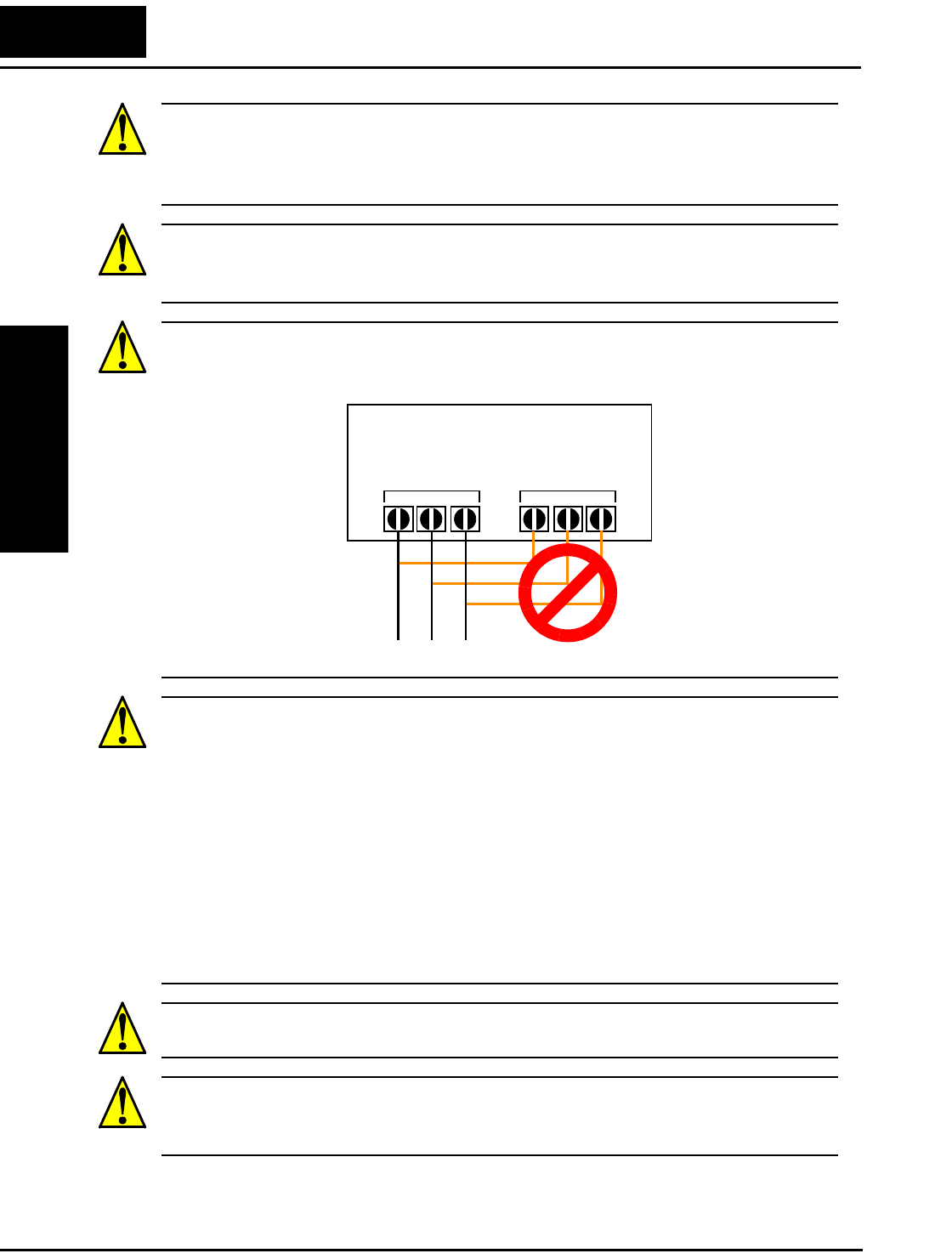
Step-by-Step Basic Installation
Inverter Mounting
and Installation
2–20
CAUTION: Be sure that the input voltage matches the inverter specifications:
• Single/Three phase 200 to 240 V 50/60 Hz (up to 2.2kW) for NFEF/NFU models
• Three phase 200 to 240V 50/60Hz (above 2.2kW) for LFU models
• Three phase 380 to 480 V 50/60Hz for HFEF models
CAUTION: If you power a 3-phase-only inverter with single phase power, you must
derate the output current. Be sure to call your Hitachi distributor for assistence. Other-
wise, there is the possibility of damage to the inverter and the danger of fire.
CAUTION: Be sure not to connect an AC power supply to the output terminals. Other-
wise, there is the possibility of damage to the inverter and the danger of injury and/or
fire.
CAUTION: Remarks for using ground fault interrupter breakers in the main power
supply:
Adjustable frequency inverters with CE-filters (RFI-filter) and shielded (screened) motor
cables have a higher leakage current toward Earth GND. Especially at the moment of
switching ON this can cause an inadvertent trip of ground fault interrupters. Because of
the rectifier on the input side of the inverter there is the possibility to stall the switch-off
function through small amounts of DC current. Please observe the following:
• Use only short time-invariant and pulse current-sensitive ground fault interrupters
with higher trigger current.
• Other components should be secured with separate ground fault interrupters.
• Ground fault interrupters in the power input wiring of an inverter are not an
absolute protection against electric shock.
CAUTION: Be sure to install a fuse in each phase of the main power supply to the
inverter. Otherwise, there is the danger of fire.
CAUTION: For motor leads, ground fault interrupter breakers and electromagnetic
contactors, be sure to size these components properly (each must have the capacity for
rated current and voltage). Otherwise, there is the danger of fire.
Power Input Output to Motor
L2002 Inverter
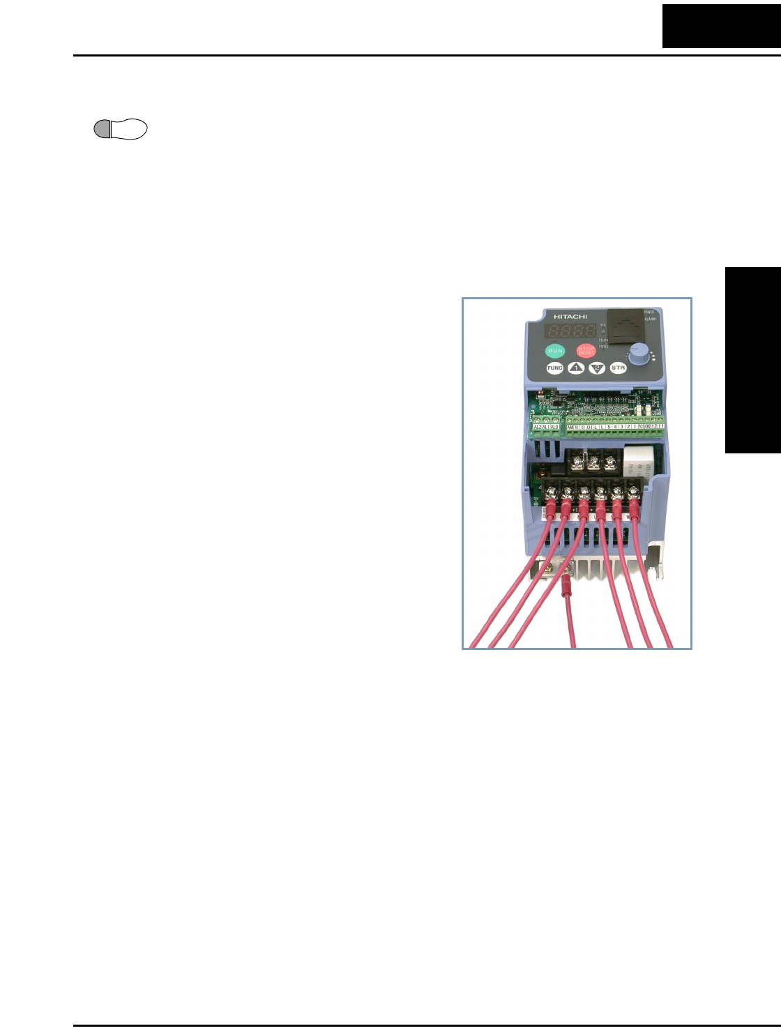
L2002 Inverter
Inverter Mounting
and Installation
2–21
Wire the Inverter Output to Motor
Step 7: The process of motor selection is beyond the scope of this manual. However, it
must be an AC induction motor with three phases. It should also come with a chassis
ground lug. If the motor does not have three power input leads, stop the installation and
verify the motor type. Other guidelines for wiring the motor include:
• Use an inverter-grade motor for maximum motor life (1600V insulation).
• For standard motors, use the AC reactor accessory if the wiring between the inverter
and motor exceeds 10 meters in length.
Simply connect the motor to the terminals
[U/T1], [V/T2], and [W/T3] as shown to the
right. This is a good time to connect the
chassis ground lug on the drive as well. The
motor chassis ground must also connect to
the same point. Use a star ground (single-
point) arrangement, and never daisy-chain the
grounds (point-to-point).
Use the same wire gauge on the motor and
chassis ground wiring as you used on the
power input wiring in the previous step. After
completing the wiring:
• Check the mechanical integrity of each
wire crimp and terminal connection.
• Replace the housing partition that covers
access to the power connections.
• Replace the front housing cover. First,
align the two hinging tabs. Then press the
cover onto the inverter until the locking
tabs click into place.
Logic Control Wiring
After completing the initial installation and powerup test in this chapter, you may need to
wire the logic signal connector for your application. For new inverter users/applications,
we highly recommend that you first complete the powerup test in this chapter without
adding any logic control wiring. Then you will be ready to set the required parameters
for logic control as covered in Chapter 4, Operations and Monitoring.
7
To Po w er
Supply
To M ot orTo Chassis
Ground
L200–004NFU2 Wiring Example
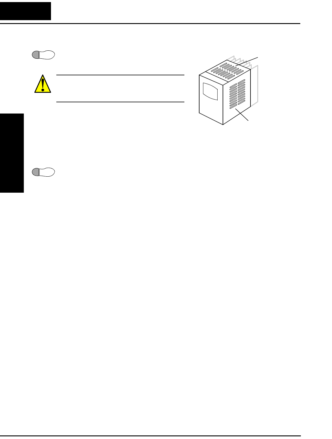
Powerup Test
Inverter Mounting
and Installation
2–22
Uncover the Inverter Vents
Step 8: After mounting and wiring the inverter,
remove any covers from the inverter housing. This
includes material over the side ventilation ports.
WARNING: Make sure the input power to the
inverter is OFF. If the drive has been powered,
leave it OFF for five minutes before continuing.
Powerup Test
Step 9: After wiring the inverter and motor, you’re ready to do a powerup test. The
procedure that follows is designed for the first-time use of the drive. Please verify the
following conditions before conducting the powerup test:
• You have followed all the steps in this chapter up to this step.
• The inverter is new, and is securely mounted to a non-flammable vertical surface
• The inverter is connected to a power source and motor.
• No additional wiring of inverter connectors or terminals has been done.
• The power supply is reliable, and the motor is a known working unit, and the motor
nameplate ratings match the inverter ratings.
• The motor is securely mounted, and is not connected to any load.
Goals for the Powerup Test
If there are any exceptions to the above conditions at this step, please take a moment to
take any measures necessary to reach this basic starting point. The specific goals of this
powerup test are:
1. Verify that the wiring to the power supply and motor is correct.
2. Demonstrate that the inverter and motor are generally compatible.
3. Get an introduction to the use of the built-in operator keypad.
The powerup test gives you an important starting point to ensure a safe and successful
application of the Hitachi inverter. We highly recommend performing this test before
proceeding to the other chapters in this manual.
8
Ventilation holes
(both sides)
Ventilation holes
(top)
9
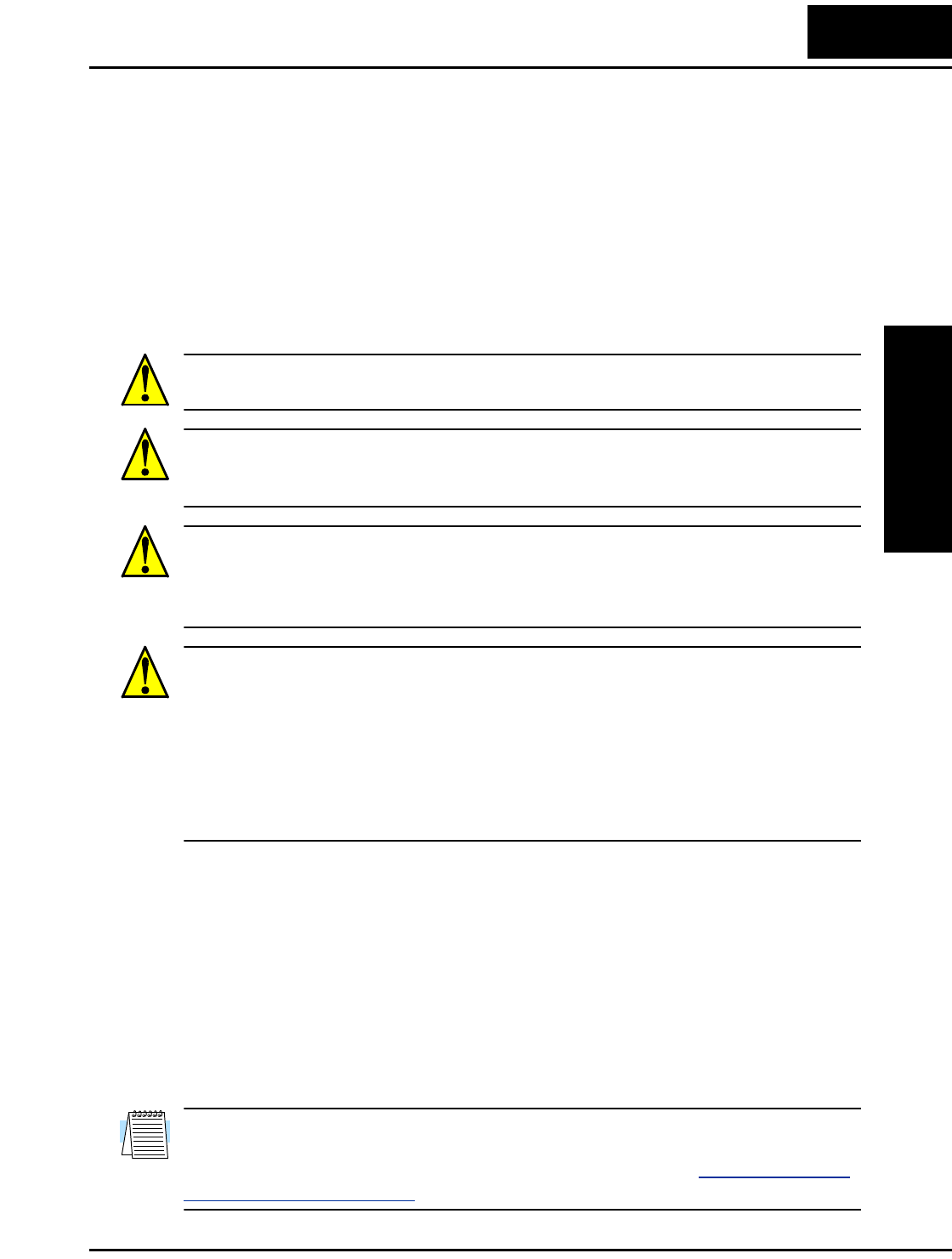
L2002 Inverter
Inverter Mounting
and Installation
2–23
Pre-test and Operational Precautions
The following instructions apply to the powerup test, or to any time the inverter is
powered and operating. Please study the following instructions and messages before
proceeding with the powerup test.
1. The power supply must have fusing suitable for the load. Check the fuse size chart
presented in Step 5, if necessary.
2. Be sure you have access to a disconnect switch for the drive input power if necessary.
However, do not turn OFF power during inverter operation unless it is an emergency.
3. Turn the keypad potentiometer to the minimum position (fully counter-clockwise).
CAUTION: The heat sink fins will have a high temperature. Be careful not to touch
them. Otherwise, there is the danger of getting burned.
CAUTION: The operation of the inverter can be easily changed from low speed to high
speed. Be sure to check the capability and limitations of the motor and machine before
operating the inverter. Otherwise, there is the danger of injury.
CAUTION: If you operate a motor at a frequency higher than the inverter standard
default setting (50Hz/60Hz), be sure to check the motor and machine specifications with
the respective manufacturer. Only operate the motor at elevated frequencies after getting
their approval. Otherwise, there is the danger of equipment damage and/or injury.
CAUTION: Check the following before and during the powerup test. Otherwise, there is
the danger of equipment damage.
• Is the shorting bar between the [+1] and [+] terminals installed? DO NOT power
or operate the inverter if the jumper is removed.
• Is the direction of the motor rotation correct?
• Did the inverter trip during acceleration or deceleration?
• Were the rpm and frequency meter readings as expected?
• Were there any abnormal motor vibrations or noise?
Powering the Inverter
If you have followed all the steps, cautions and warnings up to this point, you’re ready to
apply power. After doing so, the following events should occur:
• The POWER LED will illuminate.
• The numeric (7-segment) LEDs will display a test pattern, then stop at 0.0.
• The Hz LED will be ON.
If the motor starts running unexpectedly or any other problem occurs, press the STOP
key. Only if necessary should you remove power to the inverter as a remedy.
NOTE: If the inverter has been previously powered and programmed, the LEDs (other
than the POWER LED) may illuminate differently than as indicated above. If necessary,
you can initialize all parameters to the factory default settings. See “Restoring Factory
Default Settings” on page 6–8.
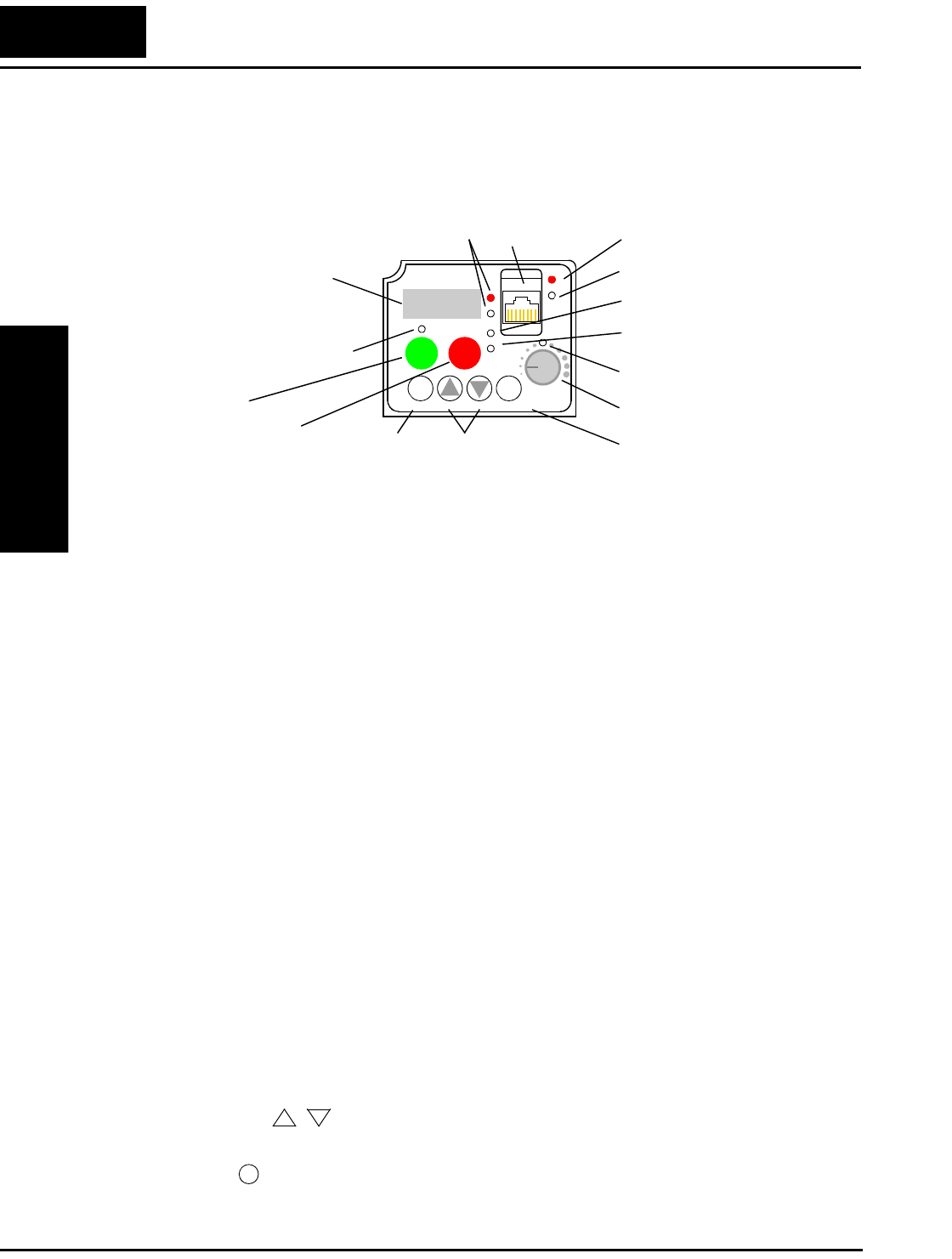
Using the Front Panel Keypad
Inverter Mounting
and Installation
2–24
Using the Front Panel Keypad
Please take a moment to familiarize yourself with the keypad layout shown in the figure
below. The display is used in programming the inverter’s parameters, as well as monitor-
ing specific parameter values during operation.
Key and Indicator Legend
•Run/Stop LED - ON when the inverter output is ON and the motor is developing
torque (Run Mode), and OFF when the inverter output is OFF (Stop Mode).
•Program/Monitor LED - This LED is ON when the inverter is ready for parameter
editing (Program Mode). It is OFF when the parameter display is monitoring data
(Monitor Mode).
•Run Key Enable LED - is ON when the inverter is ready to respond to the Run key,
OFF when the Run key is disabled.
•Run Key - Press this key to run the motor (the Run Enable LED must be ON first).
Parameter F004, Keypad Run Key Routing, determines whether the Run key generates
a Run FWD or Run REV command.
•Stop/Reset Key - Press this key to stop the motor when it is running (uses the
programmed deceleration rate). This key will also reset an alarm that has tripped.
•Potentiometer - Allows an operator to directly set the motor speed when the potenti-
ometer is enabled for output frequency control.
•Potentiometer Enable LED - ON when the potentiometer is enabled for value entry.
•Parameter Display - A 4-digit, 7-segment display for parameters and function codes.
•Display Units, Hertz/Amperes - One of these LEDs will be ON to indicate the units
associated with the parameter display.
•Power LED - This LED is ON when the power input to the inverter is ON.
•Alarm LED - ON when an inverter trip is active (alarm relay contacts will be closed).
•Function Key - This key is used to navigate through the lists of parameters and
functions for setting and monitoring parameter values.
•Up/Down ( , ) Keys - Use these keys alternately to move up or down the lists of
parameter and functions shown in the display, and increment/decrement values.
•Store ( ) Key - When the unit is in Program Mode and you have edited a parameter
value, press the Store key to write the new value to the EEPROM.
12
50.0
RUN STOP
RESET
FUNC.
STR
HITACHI
POWER
ALARM
RUN
A
Hz
PRG
Function key Up/Down keys Store key
Parameter Display
Run/Stop LED
Program/Monitor LED
Run Key Enable LED
Run Key
Stop/Reset Key
Power LED
Display Units (Hertz / Amperes) LEDs
Potentiometer Enable LED
Potentiometer
Alarm LED
Serial port
12
STR
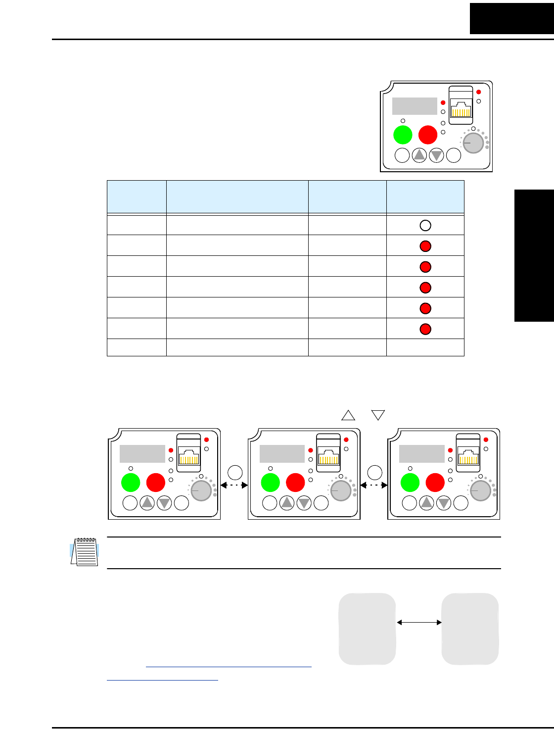
L2002 Inverter
Inverter Mounting
and Installation
2–25
Keys, Modes, and Parameters
The purpose of the keypad is to provide a way to change
modes and parameters. The term function applies to both
monitoring modes and parameters. These are all accessible
through function codes that are primarily 4-character
codes. The various functions are separated into related
groups identifiable by the left-most character, as the table
shows.
For example, function “A004” is the base frequency setting for the motor, typically
50 Hz or 60 Hz. To edit the parameter, the inverter must be in Program Mode (PRG LED
will be ON). You use the front panel keys to first select the function code “A004.” After
displaying the value for “A004,” use the Up/Down ( or ) keys to edit it.
NOTE: The inverter 7-segment display shows lower case “b” and “d,” meaning the same
as the upper case letters “B” and “D” used in this manual (for uniformity “A to F”).
The inverter automatically switches into Monitor
Mode when you access “D” Group functions. It
switches into Program Mode when you access
any other group, because they all have editable
parameters. Error codes use the “E” Group, and
appear automatically when a fault event occurs.
Refer to “Monitoring Trip Events, History, &
Conditions” on page 6–5 for error code details.
Function
Group Type (Category) of Function Mode to Access PRG LED
Indicator
“D” Monitoring functions Monitor
“F” Main profile parameters Program
“A” Standard functions Program
“B” Fine tuning functions Program
“C” Intelligent terminal functions Program
“H” Motor constant functions Program
“E” Error codes — —
12
d
001
RUN STOP
RESET
FUNC.
STR
HITACHI
POWER
ALARM
RUN
A
Hz
PRG
12
12
A- - -
RUN STOP
RESET
FUNC.
STR
HITACHI
POWER
ALARM
RUN
A
Hz
PRG
12
A004
RUN STOP
RESET
FUNC.
STR
HITACHI
POWER
ALARM
RUN
A
Hz
PRG
12
50.0
RUN STOP
RESET
FUNC.
STR
HITACHI
POWER
ALARM
RUN
A
Hz
PRG
FUNC. FUNC.
“D” Group
MONITOR PROGRAM
“A” Group
“B” Group
“C” Group
“F” Group
“H” Group
“D” Group
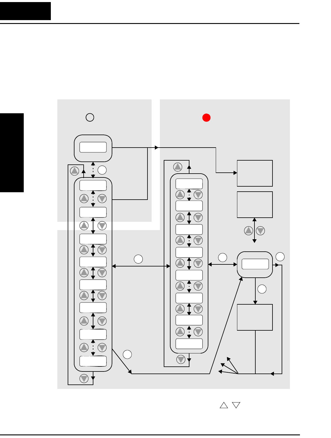
Using the Front Panel Keypad
Inverter Mounting
and Installation
2–26
Keypad Navigational Map
The L2002 Series inverter drives have many programmable functions and parameters.
Chapter 3 will cover these in detail, but you need to access just a few items to perform
the powerup test. The menu structure makes use of function codes and parameter codes
to allow programming and monitoring with only a 4-digit display and a few keys and
LEDs. So, it is important to become familiar with the basic navigational map of parame-
ters and functions in the diagram below. You may later use this map as a reference.
The navigational map shows the relationship of all resources of the inverter in one view.
In general, use the FUNC. key to move left and right, and the (arrow) keys to
move up and down.
12
2
1
Edit
Write
data to
EEPROM
Increment/
decrement
value
2
1
2
1
2
1
2
1
2
1
2
11
Select ParameterDisplay Data
2
Return to
parameter
list
2
1
2
1
2
1
2
1
2
1
2
1
2
1
Edit Parameter
000.0
d
083
d
001
H– – –
C– – –
b
–––
A– – –
F004
F001
A001
A1 55
b
001
C1 49
b
151
C001
H003
H006
123.4
2
1
PRG LED=ONPRG LED=OFF
Program ModeMonitor Mode
Select
Function
or Group
powerdown
Store as
powerup
default
FUNC. FUNC. FUNC.
FUNC.
FUNC.
STR
12
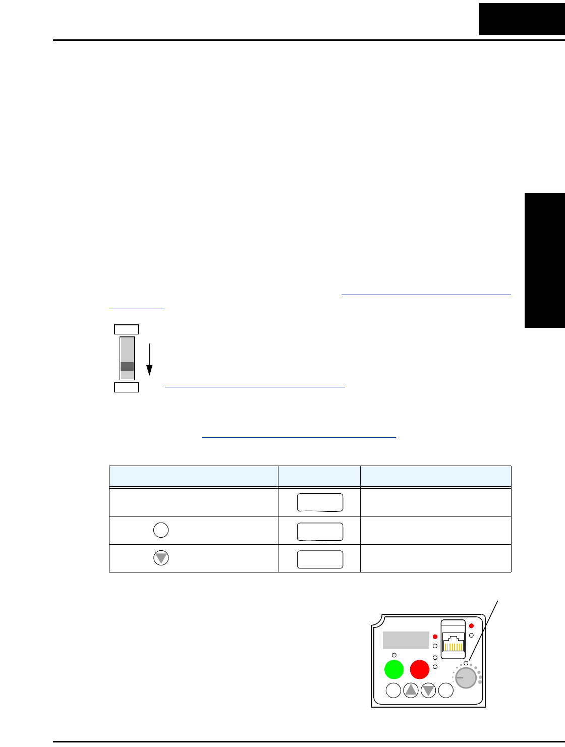
L2002 Inverter
Inverter Mounting
and Installation
2–27
Selecting Functions and Editing Parameters
To prepare to run the motor in the powerup test, this section will show how to configure
the necessary parameters:
1. Confirm the TM/PRG DIP switch setting.
2. Select the keypad potentiometer as the source of motor speed command (A001)
3. Select the keypad as the source of the RUN command (A002)
4. Set the inverter’s maximum output frequency to the motor (A003)
5. Set the motor current for proper thermal protection (B012)
6. Set the inverter’s Automatic Voltage Regulation for the motor (A082)
7. Set the number of poles for the motor (H004)
The following series of programming tables are designed for successive use. Each table
uses the previous table’s final state as the starting point. Therefore, start with the first and
continue programming until the last one. If you get lost or concerned that some of the
other parameters settings may be incorrect, refer to “Restoring Factory Default Settings”
on page 6–8.
TM/PRG DIP Switch Setting - This switch must be in the “PRG” position
(factory default) in order for A001 and A002 settings to be active. Other-
wise, the keypad will be unable to accept a Run command or set the motor
speed with the potentiometer. If the switch setting has been changed, see the
“DIP Switch Introduction” on page 2–5.
Prepare to Edit Parameters - This sequence begins with powering ON the inverter;
then it shows how to navigate to the “A” Group parameters for subsequent settings. You
can also refer to the “Keypad Navigational Map” on page 2–26 for orientation through-
out the steps.
Select the Potentiometer for Speed Command -
The inverter output frequency can be set from several
sources, including an analog input, memory setting,
or the network, for example. The powerup test uses
the keypad potentiometer as the speed control source
for your convenience. In the figure to the right, notice
the Potentiometer Enable LED, just above the knob.
If the LED is ON, the potentiometer is already
selected as the source, and you may skip this step.
Note that the default setting depends on the country.
Action Display Func./Parameter
Turn ON the inverter. Inverter output frequency
displayed (0Hz in Stop Mode).
Press the key. “D” Group selected
Press the key four times. “A” Group selected
PRG
TM
0.0
FUNC.
d
001
2
A– – –
Potentiometer Enable LED
12
50.0
RUN STOP
RESET
FUNC.
STR
HITACHI
POWER
ALARM
RUN
A
Hz
PRG
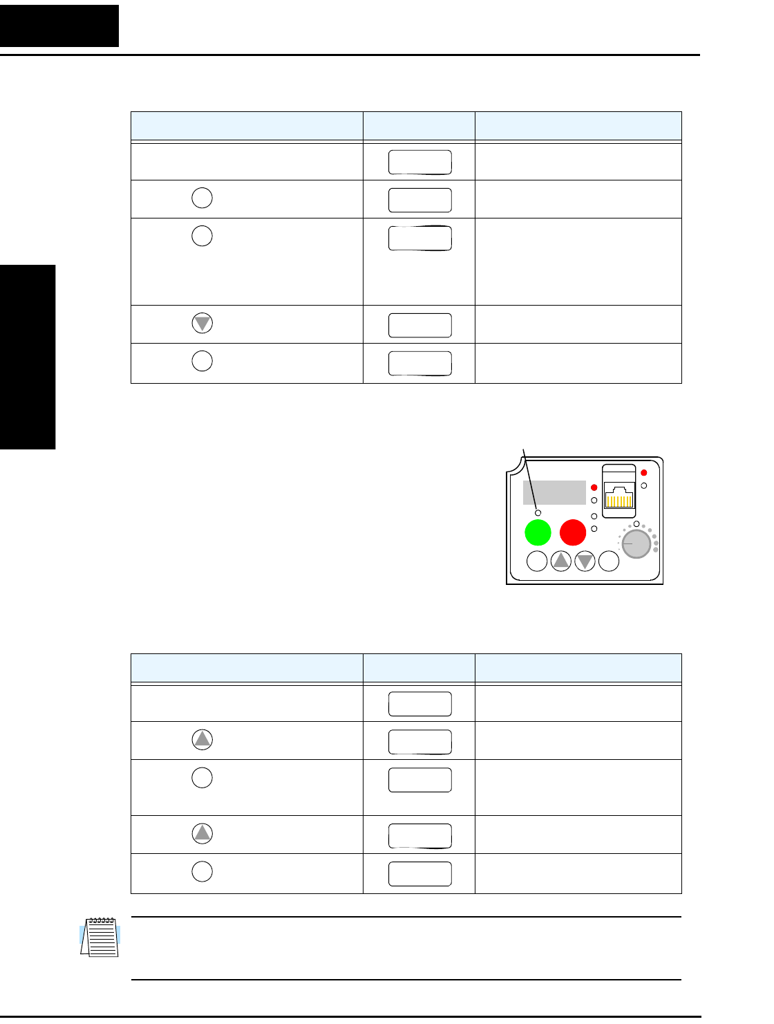
Using the Front Panel Keypad
Inverter Mounting
and Installation
2–28
If the Potentiometer Enable LED is OFF, follow the steps below.
Select the Keypad for the RUN Command - The RUN
command causes the inverter to accelerate the motor to
the selected speed. The Run command can arrive from
various sources, including the control terminals, the Run
key on the keypad, or the network. In the figure to the
right, notice the Run Key Enable LED, just above the
Run key. If the LED is ON, the Run key is already
selected as the source, and you may skip this step. Note
that the default setting depends on the country.
If the Potentiometer Enable LED is OFF, follow the steps below (the table resumes
action from the end of the previous table).
NOTE: After completing the steps above, the Run Key Enable LED will be ON. This
does not mean the motor is trying to run; it means that the RUN key is now enabled.
DO NOT press the RUN key at this time—complete the parameter setup first.
Action Display Func./Parameter
(Starting point) “A” Group selected
Press the key. Speed command source setting
Press the key again. 00 = Keypad potentiometer
01 = Control terminals
02 = Function F001 setting
03 = ModBus network
10 = Calculate function output
Press the key. 00 = potentiometer (selected)
Press the key. Stores parameter, returns to “A”
Group list
Action Display Func./Parameter
(Starting point) Speed command source setting
Press the key once. Run command source setting
Press the key. 01 = control terminals
02 = Run key on keypad
03 = ModBus network input
Press the key. 02 = keypad (selected)
Press the key. Stores parameter, returns to “A”
Group list
A– – –
FUNC.
A001
FUNC.
01
2
00
STR
A001
12
50.0
RUN STOP
RESET
FUNC.
STR
HITACHI
POWER
ALARM
RUN
A
Hz
PRG
Run Key Enable LED
A001
1
A002
FUNC.
01
1
02
STR
A002
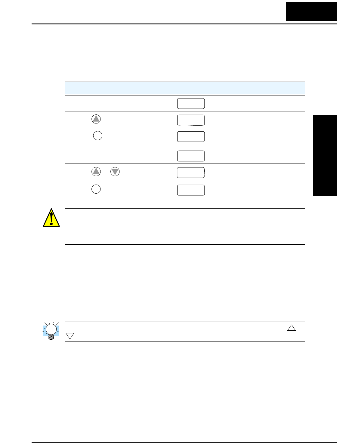
L2002 Inverter
Inverter Mounting
and Installation
2–29
Set the Motor Base Frequency - The motor is designed to operate at a specific AC
frequency. Most commercial motors are designed for 50/60 Hz operation. First, check
the motor specifications. Then follow the steps below to verify the setting or correct it
for your motor. DO NOT set it greater than 50/60 Hz unless the motor manufacturer
specifically approves operation at the higher frequency.
CAUTION: If you operate a motor at a frequency higher than the inverter standard
default setting (50Hz/60Hz), be sure to check the motor and machine specifications with
the respective manufacturer. Only operate the motor at elevated frequencies after getting
their approval. Otherwise, there is the danger of equipment damage.
Set the AVR Voltage Setting - The inverter has an Automatic Voltage Regulation (AVR)
function. It adjusts the output voltage to match the motor’s nameplate voltage rating. The
AVR smooths out fluctuations in the input power source, but note that it does not boost
the voltage in the event of a brown-out. Use the AVR setting (A082) that most closely
matches the one for your motor.
• 200V Class: 200 / 215 / 220 / 230 / 240 VAC
• 400V Class: 380 / 400 / 415 / 440 / 460 / 480 VAC
TIP: If you need to scroll through a function or parameter list, press and hold the or
key to auto-increment through the list.
To set the motor voltage, follow the steps on the following page.
Action Display Func./Parameter
(Starting point) Run command source setting
Press the key once. Base frequency setting
Press the key.
or
Default value for base frequency.
US = 60 Hz, Europe = 50 Hz.
Press the or key as needed. Set to your motor specs (your
display may be different)
Press the key. Stores parameter, returns to “A”
Group list
A002
1
A003
FUNC.
60
50
12
60
STR
A003
1
2
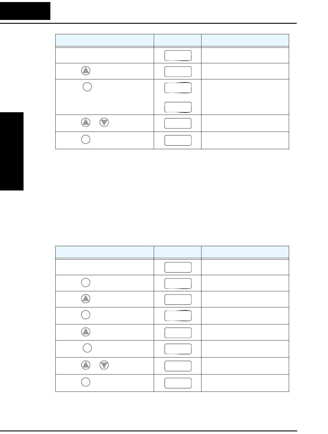
Using the Front Panel Keypad
Inverter Mounting
and Installation
2–30
Set the Motor Current - The inverter has thermal overload protection that is designed
to protect the inverter and motor from overheating due to an excessive load. The
inverter’s uses the motor’s current rating to calculate the time-based heating effect. This
protection depends on using the correct current rating for your motor. The level of
electronic thermal setting, parameter B012, is adjustable from 20% to 120% of the
inverter’s rated current. A proper configuration will also help prevent unnecessary
inverter trip events.
Read the motor’s current rating on its manufacturer’s nameplate. Then follow the steps
below to configure the inverter’s thermal overload protection setting.
Action Display Func./Parameter
(Starting point) Base frequency setting
Press the key and hold until--> AVR voltage select
Press the key.
or
Default values for AVR voltage:
200V class = 230VAC
400V class = 400VAC (–xxxFEF)
400V class = 460VAC (–xxxFU)
Press the or key as needed. Set to your motor specs (your
display may be different)
Press the key. Stores parameter, returns to “A”
Group list
Action Display Func./Parameter
(Starting point) Base frequency setting
Press the key. “A” Group selected
Press the key. “B” Group selected
Press the key. First “B” Group parameter
selected
Press the key and hold until--> Level of electronic thermal setting
Press the key. Default value will be 100% of
inverter rated current.
Press the or key as needed. Set to your motor specs (your
display may be different)
Press the key. Stores parameter, returns to “B”
Group list
A003
1
A082
FUNC.
230
400
12
21 5
STR
A082
A082
FUNC.
A– – –
1
b
–––
FUNC.
b
001
1
b
01 2
FUNC.
1.60
12
1.80
STR
B01 2
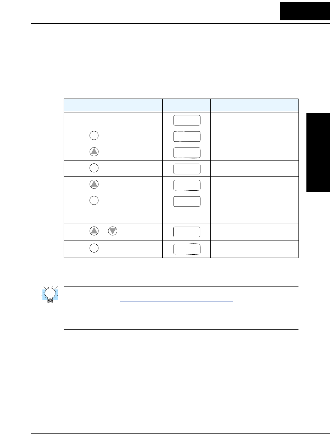
L2002 Inverter
Inverter Mounting
and Installation
2–31
Set the Number of Motor Poles - The motor’s internal winding arrangement deter-
mines its number of magnetic poles. The specifications label on the motor usually
indicates the number of poles. For proper operation, verify the parameter setting matches
the motor poles. Many industrial motors have four poles, corresponding to the default
setting in the inverter (H004).
Follow the steps in the table below to verify the motor poles setting and change it if
necessary (the table resumes action from the end of the previous table).
This step concludes the parameter setups for the inverter. You are almost ready to run the
motor for the first time!
TIP: If you became lost during any of these steps, first observe the state of the PRG
LED. Then study the “Keypad Navigational Map” on page 2–26 to determine the current
state of the keypad controls and display. As long as you do not press the STR key, no
parameters will be changed by keypad entry errors. Note that power cycling the inverter
causes it to power up Monitor Mode, displaying the value for D001 (output frequency).
The next section will show you how to monitor a particular parameter from the display.
Then you will be ready to run the motor.
Action Display Func./Parameter
(Starting point) Level of electronic thermal setting
Press the key. “B” Group selected
Press the key two times. “H” Group selected
Press the key. First “H” parameter
Press the key once. Motor poles parameter
Press the key. 2 = 2 poles
4 = 4 poles (default)
6 = 6 poles
8 = 8 poles
Press the or key as needed. Set to match your motor (your
display may be different)
Press the key. Stores parameter, returns to “H”
Group list
b
01 2
FUNC.
b
–––
1
H– – –
FUNC.
H003
1
H004
FUNC.
4
12
4
STR
H004
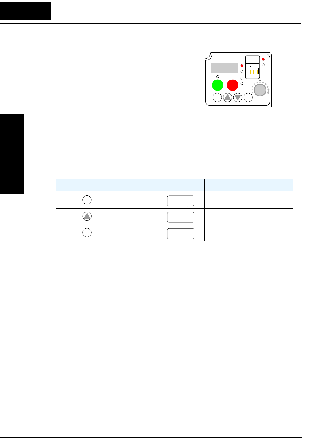
Using the Front Panel Keypad
Inverter Mounting
and Installation
2–32
Monitoring Parameters with the Display
After using the keypad for parameter editing,
it’s a good idea to switch the inverter from
Program Mode to Monitor Mode. The PRG
LED will be OFF, and the Hertz or Ampere
LED indicates the display units.
For the powerup test, monitor the motor
speed indirectly by viewing the inverter’s
output frequency. The output frequency must
not be confused with base frequency (50/
60 Hz) of the motor, or the carrier frequency (switching frequency of the inverter, in the
kHz range). The monitoring functions are in the “D” list, located near the top left of the
“Keypad Navigational Map” on page 2–26.
Output frequency (speed) monitor - Resuming keypad operation from the previous
table, follow the steps below. Or instead, you can simply power cycle the inverter, which
automatically sets the display to D001 (output frequency value).
When the inverter displays a monitor value, the PRG LED is OFF. This confirms the
inverter is not in programming mode, even while you are selecting the particular
monitoring parameter. The display shows the current speed (is zero at this point). The Hz
LED will be ON, indicating the display units. For current, the Amperes LED will be ON.
Running the Motor
If you have programmed all the parameters up to this point, you’re ready to run the
motor! First, review this checklist:
1. Verify the Power LED is ON. If not, check the power connections.
2. Verify the Potentiometer Enable LED is ON. If it is OFF, check the A001 setting.
3. Verify the Run Key Enable LED is ON. If it is OFF, check the A002 setting.
4. Verify the PRG LED is OFF. If it is ON, review the instructions above.
5. Make sure the motor is disconnected from any mechanical load.
6. Turn the potentiometer to the minimum position (completely counter clock-wise).
7. Now, press the RUN key on the keypad. The RUN LED will turn ON.
8. Slowly increase the potentiometer setting in clockwise fashion. The motor should
start turning.
9. Press the STOP key to stop the motor rotation.
Action Display Func./Parameter
Press the key. “H” Group selected
Press the key. Output frequency selected
Press the key. Output frequency displayed
12
50.0
RUN STOP
RESET
FUNC.
STR
HITACHI
POWER
ALARM
RUN
A
Hz
PRG
FUNC.
H– – –
1
d
001
FUNC.
0.0
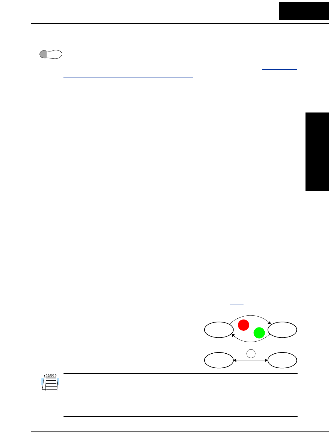
L2002 Inverter
Inverter Mounting
and Installation
2–33
Powerup Test Observations and Summary
Step 10: Reading this section will help you make some useful observations when first
running the motor.
Error Codes - If the inverter displays an error code (format is “E X X”), see “Monitoring
Trip Events, History, & Conditions” on page 6–5 to interpret and clear the error.
Acceleration and Deceleration - The L2002 inverter has programmable acceleration
and deceleration values. The test procedure left these at the default value, 10 seconds.
You can observe this by setting the potentiometer at about half speed before running the
motor. Then press RUN, and the motor will take 5 seconds to reach a steady speed. Press
the STOP key to see a 5 second deceleration to a stop.
State of Inverter at Stop - If you adjust the motor’s speed to zero, the motor will slow to
a near stop, and the inverter turns the outputs OFF. The high-performance L2002 can
rotate at a very slow speed with high torque output, but not zero (must use servo systems
with position feedback for that feature). This characteristic means you must use a
mechanical brake for some applications.
Interpreting the Display - First, refer to the output frequency display readout. The
maximum frequency setting (parameter A004) defaults to 50 Hz or 60 Hz (Europe and
United States, respectively) for your application.
Example: Suppose a 4-pole motor is rated for 60 Hz operation, so the inverter is config-
ured to output 60 Hz at full scale. Use the following formula to calculate the RPM.
The theoretical speed for the motor is 1800 RPM (speed of torque vector rotation).
However, the motor cannot generate torque unless its shaft turns at a slightly different
speed. This difference is called slip. So it’s common to see a rated speed of approxi-
mately 1750 RPM on a 60 Hz, 4-pole motor. Using a tachometer to measure shaft speed,
you can see the difference between the inverter output frequency and the actual motor
speed. The slip increases slightly as the motor’s load increases. This is why the inverter
output value is called “frequency,” since it is not exactly equal to motor speed. You can
program the inverter to display output frequency in units more directly related to the load
speed by entering a constant (discussed more in depth on page 3–41).
Run/Stop Versus Monitor/Program Modes –
The Run LED on the inverter is ON in Run Mode,
and OFF in Stop Mode. The Program LED is ON
when the inverter is in Program Mode, and OFF for
Monitor Mode. All four mode combinations are
possible. The diagram to the right depicts the
modes and the mode transitions via keypad.
NOTE: Some factory automation devices such as PLCs have alternate Run/Program
modes; the device is in either one mode or the other. In the Hitachi inverter, however,
Run Mode alternates with Stop Mode, and Program Mode alternates with Monitor
Mode. This arrangement lets you program some values while the inverter is operating—
providing flexibility for maintenance personnel.
10
Speed in RPM Frequency 60×
Pairs of poles
---------------------------------------- Frequency 120×
# of poles
------------------------------------------- 60 120×
4
---------------------1800RPM== ==
Run Stop
Monitor Program
RUN
STOP
RESET
FUNC.


Configuring
Drive Parameters
In This Chapter.... page
— Choosing a Programming Device ................... 2
— Using Keypad Devices.................................... 3
— “D” Group: Monitoring Functions..................... 6
— “F” Group: Main Profile Parameters................ 9
— “A” Group: Standard Functions ..................... 10
— “B” Group: Fine Tuning Functions................. 33
— “C” Group: Intelligent Terminal Functions...... 47
— “H” Group: Motor Constants Functions ......... 63
— “P” Group: Expansion Card Functions .......... 64
3

Choosing a Programming Device
Configuring
Drive Parameters
3–2
Choosing a Programming Device
Introduction
Hitachi variable frequency drives (inverters) use the latest electronics technology for
getting the right AC waveform to the motor at the right time. The benefits are many,
including energy savings and higher machine output or productivity. The flexibility
required to handle a broad range of applications has required ever more configurable
options and parameters—inverters are now a complex industrial automation component.
And this can make a product seem difficult to use, but the goal of this chapter is to make
this easier for you.
As the powerup test in Chapter 2 demonstrated, you do not have to program very many
parameters to run the motor. In fact, most applications would benefit only from program-
ming just a few, specific parameters. This chapter will explain the purpose of each set of
parameters, and help you choose the ones that are important to your application.
If you are developing a new application for the inverter and a motor, finding the right
parameters to change is mostly an exercise in optimization. Therefore, it is okay to begin
running the motor with a loosely tuned system. By making specific, individual changes
and observing their effects, you can achieve a finely tuned system.
Introduction to Inverter Programming
The front panel keypad is the first and best way to get to know the inverter’s capabilities.
Every function or programmable parameter is accessible from the keypad. The other
devices simply imitate the keypad’s layout and inverter access, while adding another
valuable aspect to the system. For example, the Digital Operator/Copy Unit can transfer
one inverter’s parameter settings to another inverter, while still providing standard
operator keypad control. In this way, you can use a variety of programming devices with
basically the same keypad skills. The following table shows various programming
options, the features unique to each device, and the cables required.
NOTE: When an external digital operator device such as an OPE–SRmini or
SRW–0EX is connected to the inverter, the inverter’s keypad is automatically disabled
(except for the Stop Key).
NOTE: When using the SRW–0EX Copy Unit, you cannot copy parameters between
L200 and L2002 series inverters, nor between SJ2002 and L2002 series inverters.
Device Part
Number
Parameter
Access
Parameter
setting storage
Cables (choose one)
Part number Length
External inverter
keypad
OPE–SRmini Monitor and
program
EEPROM in
inverter
ICS–1 1 meter
ICS–3 3 meters
Digital Operator/
Copy Unit
SRW–0EX Monitor and
program
Read Function
downloads to
EEPROM in
operator unit
ICS–1 1 meter
ICS–3 3 meters

L2002 Inverter
Configuring
Drive Parameters
3–3
Using Keypad Devices
The L2002 Series inverter front keypad contains all the elements for both monitoring and
programming parameters. The keypad layout is pictured below. All other programming
devices for the inverter have a similar key arrangement and function.
Key and Indicator Legend
•Run/Stop LED - ON when the inverter output is ON and the motor is developing
torque (Run Mode), and OFF when the inverter output is OFF (Stop Mode).
•Program/Monitor LED - This LED is ON when the inverter is ready for parameter
editing (Program Mode). It is OFF when the parameter display is monitoring data
(Monitor Mode).
•Run Key Enable LED - is ON when the inverter is ready to respond to the Run key,
OFF when the Run key is disabled.
•Run Key - Press this key to run the motor (the Run Enable LED must be ON first).
Parameter F004, Keypad Run Key Routing, determines whether the Run key generates
a Run FWD or Run REV command.
•Stop/Reset Key - Press this key to stop the motor when it is running (uses the
programmed deceleration rate). This key will also reset an alarm that has tripped.
•Potentiometer - Allows an operator to directly set the motor speed when the potenti-
ometer is enabled for output frequency control.
•Potentiometer Enable LED - ON when the potentiometer is enabled for value entry.
•Parameter Display - A 4-digit, 7-segment display for parameters and function codes.
•Display Units, Hertz/Amperes - One of these LEDs will be ON to indicate the units
associated with the parameter display.
•Power LED - This LED is ON when the power input to the inverter is ON.
•Alarm LED - ON when an inverter trip is active (alarm relay contacts will be closed).
•Function Key - This key is used to navigate through the lists of parameters and
functions for setting and monitoring parameter values.
•Up/Down ( , ) Keys - Use these keys alternately to move up or down the lists of
parameter and functions shown in the display, and increment/decrement values.
•Store ( ) Key - When the unit is in Program Mode and you have edited a parameter
value, press the Store key to write the new value to the EEPROM.
12
50.0
RUN STOP
RESET
FUNC.
STR
HITACHI
POWER
ALARM
RUN
A
Hz
PRG
Function key Up/Down keys Store key
Parameter Display
Run/Stop LED
Program/Monitor LED
Run Key Enable LED
Run Key
Stop/Reset Key
Power LED
Display Units (Hertz / Amperes) LEDs
Potentiometer Enable LED
Potentiometer
Alarm LED
Serial port
12
STR
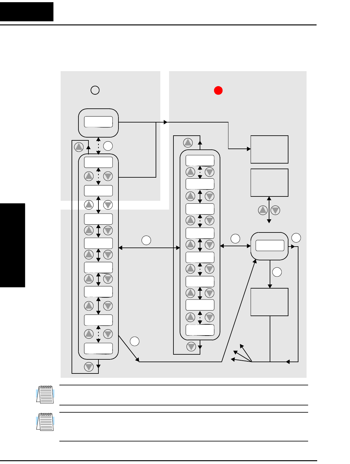
Using Keypad Devices
Configuring
Drive Parameters
3–4
Keypad Navigational Map
You can use the inverter’s front panel keypad to navigate to any parameter or function.
The diagram below shows the basic navigational map to access these items.
NOTE: The inverter 7-segment display shows lower case “b” and “d,” meaning the same
as the upper case letters “B” and “D” used in this manual (for uniformity “A to F”).
NOTE: The Store Key saves the edited parameter (shown in the display) to the inverter’s
EEPROM. Upload or download of parameters to/from external devices is accomplished
through a different command—do not confuse Store with Download or Upload.
12
2
1
Edit
Write
data to
EEPROM
Increment/
decrement
value
2
1
2
1
2
1
2
1
2
1
2
11
Select ParameterDisplay Data
2
Return to
parameter
list
2
1
2
1
2
1
2
1
2
1
2
1
2
1
Edit Parameter
000.0
d
083
d
001
H– – –
C– – –
b
–––
A– – –
F004
F001
A001
A1 55
b
001
C1 49
b
151
C001
H003
H006
123.4
2
1
PRG LED=ONPRG LED=OFF
Program ModeMonitor Mode
Select
Function
or Group
powerdown
Store as
powerup
default
FUNC. FUNC. FUNC.
FUNC.
FUNC.
STR
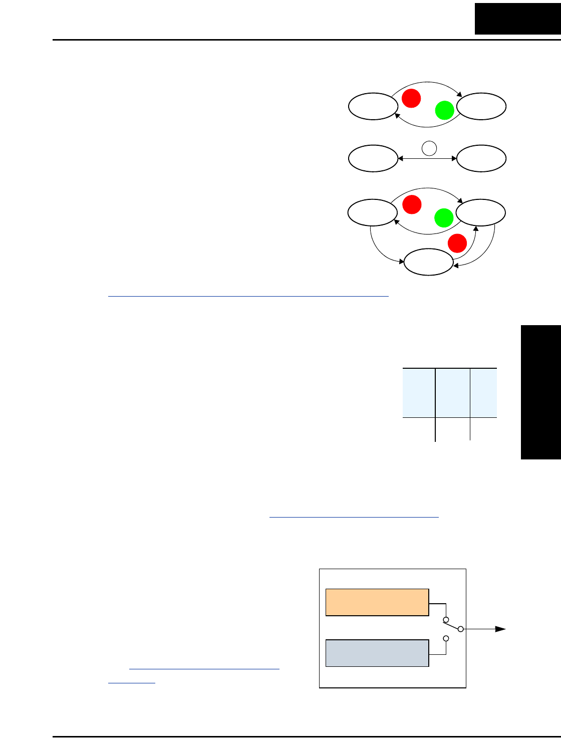
L2002 Inverter
Configuring
Drive Parameters
3–5
Operational Modes
The RUN and PRG LEDs tell just part of the story;
Run Mode and Program Modes are independent
modes, not opposite modes. In the state diagram to
the right, Run alternates with Stop, and Program
Mode alternates with Monitor Mode. This is a very
important ability, for it shows that a technician can
approach a running machine and change some
parameters without shutting down the machine.
The occurrence of a fault during operation will
cause the inverter to enter the Trip Mode as shown.
An event such as an output overload will cause the
inverter to exit the Run Mode and turn OFF its
output to the motor. In the Trip Mode, any request
to run the motor is ignored. You must clear the
error by pressing the Stop/Reset switch. See
“Monitoring Trip Events, History, & Conditions” on page 6–5.
Run Mode Edits
The inverter can be in Run Mode (inverter output is controlling motor) and still allow
you to edit certain parameters. This is useful in applications that must run continuously.
The parameter tables in this chapter have a column titled “Run
Mode Edit.” An Ex mark ✘ means the parameter cannot be
edited; a Check mark ✔ means the parameter can be edited.
The table example to the right contains two adjacent marks
“✘ ✔”. These two marks (that can also be“✘ ✘” or “✔ ✔”)
correspond to low-access or high-access levels to Run Mode
edits (note Lo and Hi in column heading).
The Software Lock Setting (parameter B031) determines when Run Mode access is in
effect and access permission in other conditions, as well. It is the responsibility of the
user to choose a useful and safe software lock setting for the inverter operating condi-
tions and personnel. Please refer to “Software Lock Mode” on page 3–39.
Control Algorithms
The motor control program in the L2002
inverter has two sinusoidal PWM switching
algorithms. The intent is that you select the
best algorithm for the motor characteristics
in your application. Both algorithms
generate the frequency output in a unique
way. Once configured, the algorithm is the
basis for other parameter settings as well
(see “Torque Control Algorithms” on
page 3–18). Therefore, choose the best
algorithm early in your application design
process.
Run Stop
Monitor Program
RUN
STOP
RESET
FUNC.
Run Stop
Trip
Fault
Fault
STOP
RESET
RUN
STOP
RESET
Run
Mode
Edit
Lo Hi
✘ ✔
Output
Variable freq. control,
constant torque
Variable freq. control,
reduced torque
Inverter Control Algorithms
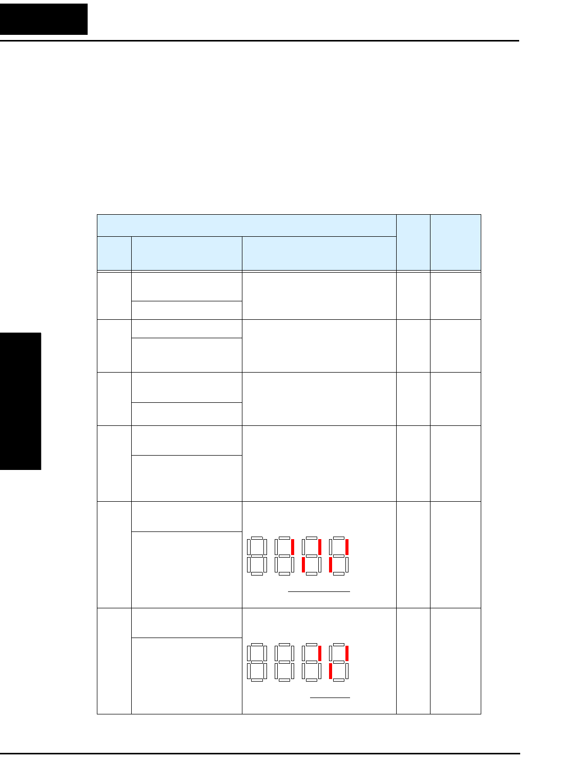
“D” Group: Monitoring Functions
Configuring
Drive Parameters
3–6
“D” Group: Monitoring Functions
You can access important system parameter values with the “D” Group monitoring
functions, whether the inverter is in Run Mode or Stop Mode. After selecting the
function code number for the parameter you want to monitor, press the Function key
once to show the value on the display. In functions D005 and D006, the intelligent termi-
nals use individual segments of the display to show ON/OFF status.
If the inverter display is set to monitor a parameter and powerdown occurs, the inverter
stores the present monitor function setting. For your convenience, the display automati-
cally returns to the previously monitored parameter upon the next powerup.
“D” Function Run
Mode
Edit
Units
Func.
Code
Name /
SRW Display Description
D001 Output frequency
monitor
Real-time display of output
frequency to motor, from
0.0 to 400.0 Hz
—Hz
FM 0000.00Hz
D002 Output current monitor Filtered display of output current
to motor (100 ms internal filter
time constant), range is
0 to 200% of inverter rated current
—A
Iout 0000.0A
D003 Rotation direction
monitor
Three different indications:
“F”..... Forward
“o” .. Stop
“r”..... Reverse
——
Dir STOP
D004 Process variable (PV),
PID feedback monitor
Displays the scaled PID process
variable (feedback) value (A075 is
scale factor),
0.00 to 99.99, 100.0 to 999.9,
1000. to 9999., 1000 to 999,
and 10000 to 99900
— % times
constant
FB 00000.00%
D005 Intelligent input
terminal status
Displays the state of the intelligent
input terminals:
——
IN-TM LLLLL
D006 Intelligent output
terminal status
Displays the state of the intelligent
output terminals:
——
OUT-TM LLL
ON
OFF
12345
Terminal numbers
ON
OFF
1112
Terminal numbers
AL

L2002 Inverter
Configuring
Drive Parameters
3–7
Trip Event and History Monitoring
The trip event and history monitoring feature lets you cycle through related information
using the keypad. See “Monitoring Trip Events, History, & Conditions” on page 6–5 for
more details.
D007 Scaled output frequency
monitor
Displays the output frequency
scaled by the constant in B086.
Decimal point indicates range:
XX.XX 0.00 to 99.99
XXX.X 100.0 to 999.9
XXXX. 1000. to 9999.
XXXX 1000 to 9999 (x10=
10000 to 99999)
— Hz times
constant
F-Cnv 00000.00
D013 Output voltage monitor Voltage of output to motor,
range is 0.0 to 600.0V
—V
Vout 00000V
D016 Cumulative operation
RUN time monitor
Displays total time the inverter has
been in RUN mode in hours.
Range is 0 to 9999 /
1000 to 9999 /
Γ100 to Γ999 (10,000 to 99,900)
— hours
RUN 0000000hr
D017 Cumulative power-on
time monitor
Displays total time the inverter has
been in RUN mode in hours.
Range is 0 to 9999 /
1000 to 9999 /
Γ100 to Γ999 (10,000 to 99,900)
— hours
ON 0000000hr
“D” Function Run
Mode
Edit
Units
Func.
Code
Name /
SRW Display Description
“D” Function Run
Mode
Edit
Units
Func.
Code
Name /
SRW Display Description
D080 Trip counter Number of trip events,
range is 0. to 9999
— events
ERR CNT 00000
D081 Trip monitor 1 Displays trip event informa-
tion:
•Error code
•Output freq. at trip point
•Motor current at trip point
•DC bus voltage at trip point
•Cumulative inverter opera-
tion time at trip point
•Cumulative power-ON time
at trip point
——
ERR 1 ########
D082 Trip monitor 2 — —
ERR 2 ########
D083 Trip monitor 3 — —
ERR 3 ########
“D” Group: Monitoring Functions
Configuring
Drive Parameters
3–8
Local Monitoring During Network Operation
The L2002 inverter’s serial port may be connected to a network or to an external digital
operator. During those times, the inverter keypad keys will not function (except for the
Stop key). However, the inverter’s 4-digit display still provides the Monitor Mode
function, displaying any of the parameters D001 to D007. Function B089, Monitor
Display Select for Networked Inverter, determines the particular D00x parameter
displayed. Refer to the table below.
When monitoring the inverter during network operation, please note the following:
• The inverter display will monitor D00x functions according to B089 setting when...
• the OPE/485 DIP switch is set to the “485” position, or
• a device is already connected to the inverter’s serial port at inverter powerup.
• During network operation, the inverter keypad will also display error codes for
inverter trip events. Use the Stop key or inverter Reset function to clear the error. Refer
to “Error Codes” on page 6–5 to interpret the error codes.
• The Stop key can be disabled, if you prefer, by using function B087.
B089 Monitor Display Select for Networked Inverter
Option
Code
Monitor
Code Monitor Function Name
01 D001 Output frequency monitor
02 D002 Output current monitor
03 D003 Rotation direction monitor
04 D004 Process variable (PV), PID feedback monitor
05 D005 Intelligent input terminal status
06 D006 Intelligent output terminal status
07 D007 Scaled output frequency monitor
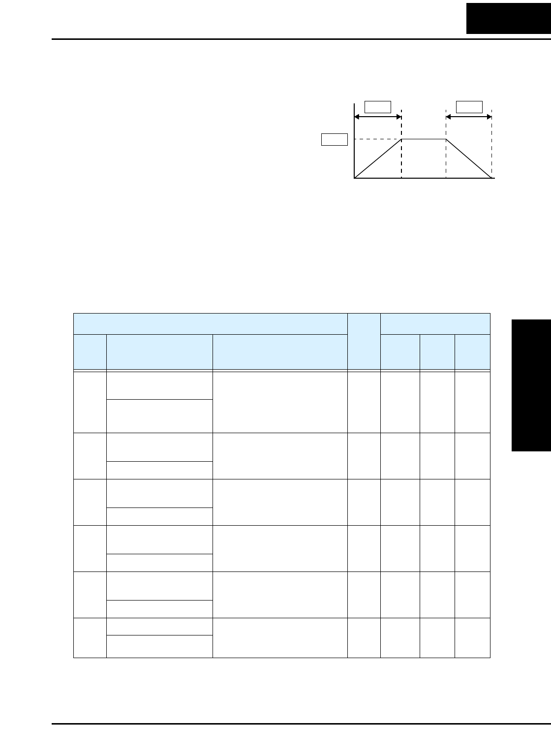
L2002 Inverter
Configuring
Drive Parameters
3–9
“F” Group: Main Profile Parameters
The basic frequency (speed) profile is
defined by parameters contained in the
“F” Group as shown to the right. The set
running frequency is in Hz, but accelera-
tion and deceleration are specified in the
time duration of the ramp (from zero to
maximum frequency, or from maximum
frequency to zero). The motor direction
parameter determines whether the keypad
Run key produces a FWD or REV command. This parameter does not affect the intelli-
gent terminal [FWD] and [REV] functions, which you configure separately.
Acceleration 1 and Deceleration 1 are the standard default accel and decel values for the
main profile. Accel and decel values for an alternative profile are specified by using
parameters Ax92 through Ax93. The motor direction selection (F004) determines the
direction of rotation as commanded only from the keypad. This setting applies to any
motor profile (1st or 2nd) in use at a particular time
Output
frequency
t
0
F002
F001
F003
“F” Function Run
Mode
Edit
Lo Hi
Defaults
Func.
Code
Name /
SRW Display Description –FE(F)
(EU)
–FU
(USA) Units
F001 Output frequency
setting
Standard default target
frequency that determines
constant motor speed,
range is 0.0 / start frequency
to 400 Hz
✔ ✔ 0.0 0.0 Hz
VR 0000.0Hz
F002 Acceleration (1) time
setting
Standard default acceleration,
range is 0.01 to 3000 sec.
✔ ✔ 10.0 10.0 sec.
ACC 1 010.00s
F202 Acceleration (1) time
setting, 2nd motor
Standard default acceleration,
2nd motor,
range is 0.01 to 3000 sec.
✔ ✔ 10.0 10.0 sec.
2ACC1 010.00s
F003 Deceleration (1) time
setting
Standard default deceleration,
range is 0.01 to 3000 sec.
✔ ✔ 10.0 10.0 sec.
DEC 1 010.00s
F203 Deceleration (1) time
setting, 2nd motor
Standard default deceleration,
2nd motor,
range is 0.01 to 3000 sec.
✔ ✔ 10.0 10.0 sec.
2DEC1 010.00s
F004 Keypad Run key routing Two options; select codes:
00 .. Forward
01 .. Reverse
✘ ✘ 00 00 —
DIG-RUN FWD
“A” Group: Standard Functions
Configuring
Drive Parameters
3–10
“A” Group: Standard Functions
Control Source Settings
The inverter provides flexibility in how you control Run/Stop operation and set the
output frequency (motor speed). It has other control sources that can override the A001/
A002 settings. Parameter A001 sets the source selection for the inverter’s output
frequency. Parameter A002 selects the Run command source (for FW or RV Run
commands). The default settings use the input terminals for –FE(F) (European) models,
and the keypad for –FU (USA) models.
Frequency Source Setting - For parameter A001, the following table provides a further
description of each option, and a reference to other page(s) for more information.
“A” Function Run
Mode
Edit
Lo Hi
Defaults
Func.
Code
Name /
SRW Display Description –FE(F)
(EU)
–FU
(USA) Units
A001 Frequency source
setting
Five options; select codes:
00... Keypad potentiometer
01... Control terminal
02... Function F001 setting
03... ModBus network input
10... Calculate function output
✘ ✘ 01 00 —
F-COM VR
A201 Frequency source
setting, 2nd motor
✘ ✘ 01 00 —
2F-COM VR
A002 Run command source
setting
Three options; select codes:
01... Control terminal
02... Run key on keypad, or
digital operator
03... ModBus network input
✘ ✘ 01 02 —
OPE-Mode REM
A202 Run command source
setting, 2nd motor
✘ ✘ 01 02 —
2OPE-Mode REM
Code Frequency Source Refer to page(s)...
00 Keypad potentiometer - The range of rotation of the knob
matches the range defined by B082 (Start frequency adjust-
ment) to A004 (Maximum frequency setting)
2–24
01 Control terminal - The active analog input signal on analog
terminals [O] or [OI] sets the output frequency
4–53, 3–14, 3–59
02 Function F001 setting - The value in F001 is a constant, used
for the output frequency
3–9
03 ModBus network input - The network has a dedicated
register for inverter output frequency
B–19
10 Calculate function output - The Calculate function has user-
selectable analog input sources (A and B). The output can be
the sum, difference, or product (+, –, x) of the two outputs.
3–30
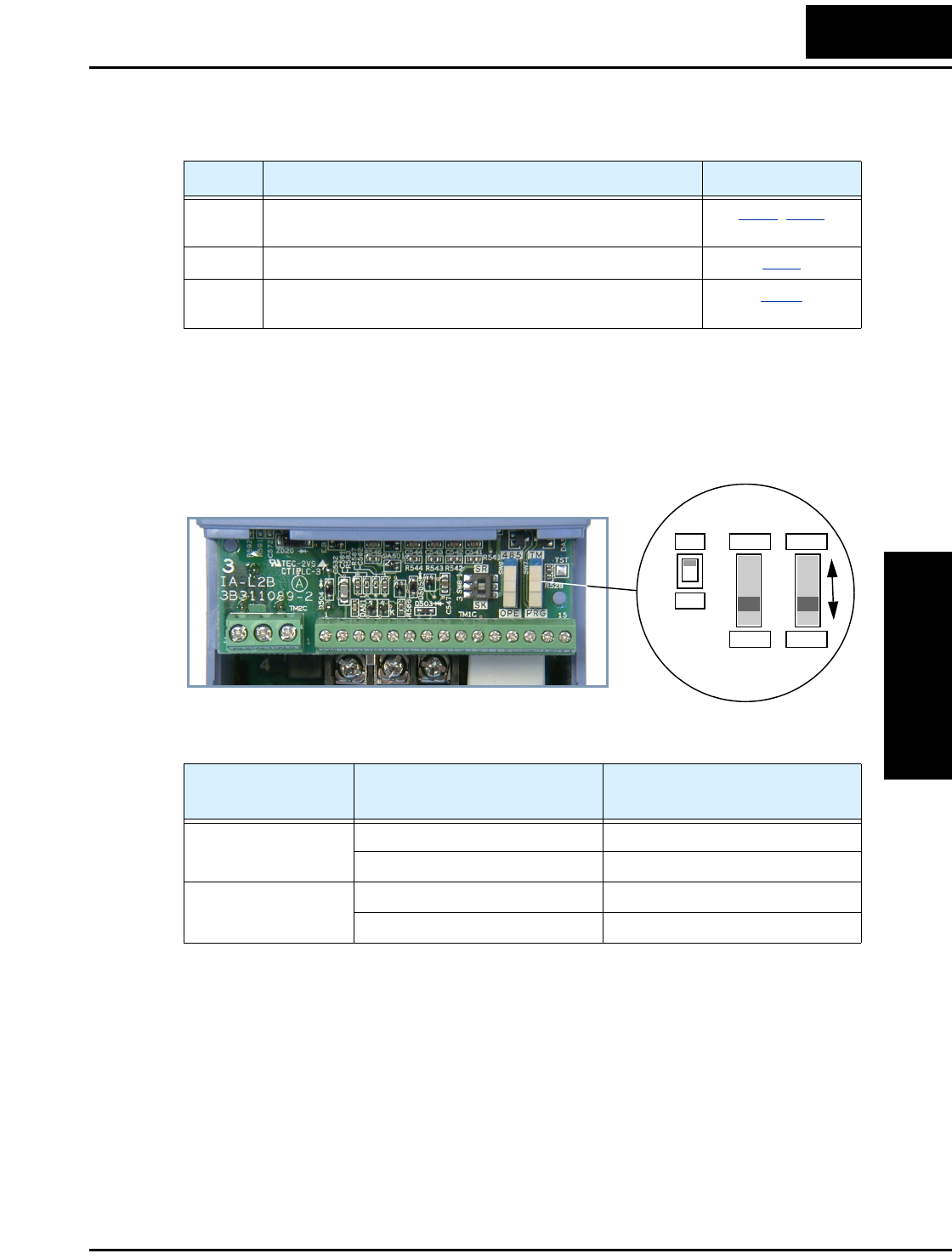
L2002 Inverter
Configuring
Drive Parameters
3–11
Run Command Source Setting - For parameter A002, the following table provides a
further description of each option, and a reference to other page(s) for more information
A001/A002 Override Sources - The inverter allows some sources to override the
settings for output frequency and the Run command in A001 and A002. This provides
flexibility for applications that occasionally need to use a different source, leaving the
standard settings in A001/A002. In particular, note the TM/PRG (Terminal/Program)
DIP switch behind the front panel cover shown below. It is the switch to the right.
The TM/PRG switch setting forces terminal operation, according to the table below:
When A001 = 01 and A002 = 01, the inverter control source is the terminals, regardless
of the TM/PRG switch position. When A001 and A002 setting is not 01, then the
TM/PRG switch can force terminal input control.
Code Run Command Source Refer to page(s)...
01 Control terminal - The [FW] or [RV] input terminals control
Run/Stop operation
4–12, 3–49
02 Keypad Run key - The Run and Stop keys provide control 2–24
03 ModBus network input - The network has a dedicated coil
for Run/ Stop command and a coil for FW/RV
B–19
TM/PRG
Switch Position Item Source
PRG (Program) Output frequency source Specified by A001 setting
Run command source Specified by A002 setting
TM (Terminal) Output frequency source [O] or [OI] analog input terminal
Run command source [FW] and/or [RV] input terminals
SR
SK
OPE
485
PRG
TM
“A” Group: Standard Functions
Configuring
Drive Parameters
3–12
The inverter has other control sources that can temporarily override the parameter A001
setting, forcing a different output frequency source. The following table lists all
frequency source setting methods and their relative priority (“1” is the highest priority).
The inverter also has other control sources that can temporarily override the parameter
A002 setting, forcing a different Run command source. The following table lists all Run
command setting methods and their relative priority (“1” is the highest priority).
Priority A001 Frequency Source Setting Method Refer to page...
1 [CF1] to [CF4] Multi-speed terminals 4–13
2 [OPE] Operator Control intelligent input 4–31
3 [F-TM] intelligent input 4–33
4 [AT] terminal 4–23
5 TM/PRG DIP Switch - (if switch is in “TM” position) 3–11
6 A001 Frequency source setting 3–10
Priority A002 Run Command Setting Method Refer to page...
1 [OPE] Operator Control intelligent input 4–31
2 [F-TM] intelligent input 4–33
3 TM/PRG DIP Switch - (if switch is in “TM” position) 3–11
4 A002 Run command source setting 3–10
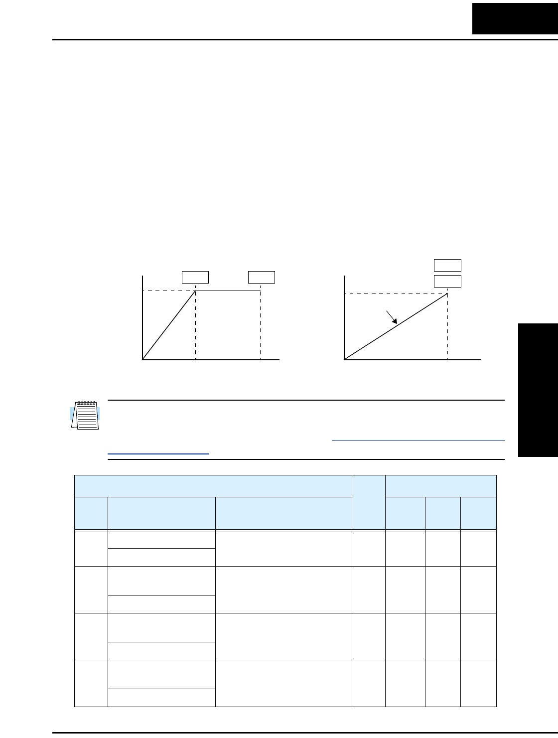
L2002 Inverter
Configuring
Drive Parameters
3–13
Basic Parameter Settings
These settings affect the most fundamental behavior of the inverter—the outputs to the
motor. The frequency of the inverter’s AC output determines the motor speed. You may
select from three different sources for the reference speed. During application develop-
ment you may prefer using the potentiometer, but you may switch to an external source
(control terminal setting) in the finished application, for example.
The base frequency and maximum frequency settings interact according to the graph
below (left). The inverter output operation follows the constant V/f curve until it reaches
the full-scale output voltage at the base frequency. This initial straight line is the
constant-torque part of the operating characteristic. The horizontal line over to the
maximum frequency serves to let the motor run faster, but at a reduced torque. This is the
constant-power operating range. If you want the motor to output constant torque over its
entire operating range (limited to the motor nameplate voltage and frequency rating),
then set the base frequency and maximum frequency equal as shown (below right).
NOTE: The “2nd motor” settings in the tables in this chapter store an alternate set of
parameters for a second motor. The inverter can use the 1st set or 2nd set of parameters
to generate the output frequency to the motor. See “Configuring the Inverter for Multiple
Motors” on page 4–58.
Base
Frequency
Maximum
Frequency
Base frequency =
maximum frequency
VV
100% 100%
ff
Constant torque
00
A003 A004
A003
A004
“A” Function Run
Mode
Edit
Defaults
Func.
Code
Name /
SRW Display Description –FE(F)
(EU)
–FU
(USA) Units
A003 Base frequency setting Settable from 30 Hz to the
maximum frequency
✘ ✘ 50.0 60.0 Hz
F-BASE 00060Hz
A203 Base frequency setting,
2nd motor
Settable from 30 Hz to the 2nd
maximum frequency
✘ ✘ 50.0 60.0 Hz
2F-BASE 00060Hz
A004 Maximum frequency
setting
Settable from the base
frequency up to 400 Hz
✘ ✘ 50.0 60.0 Hz
F-MAX 00060Hz
A204 Maximum frequency
setting, 2nd motor
Settable from the 2nd base
frequency up to 400 Hz
✘ ✘ 50.0 60.0 Hz
2F-MAX 00060Hz
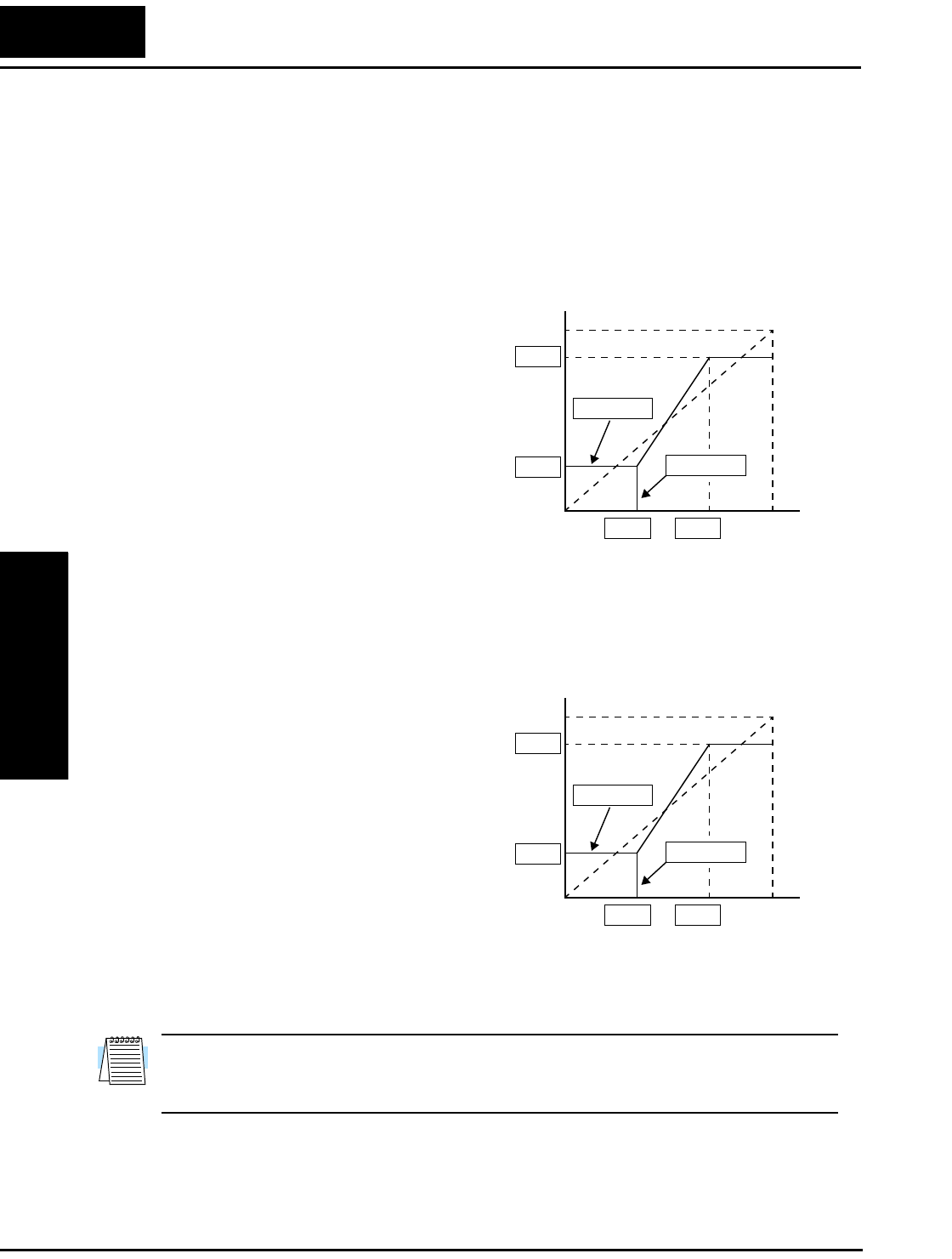
“A” Group: Standard Functions
Configuring
Drive Parameters
3–14
Analog Input Settings
The inverter has the capability to accept an external analog input that can command the
output frequency to the motor. Voltage input (0 –10V) and current input (4–20mA) are
available on separate terminals ([O] and [OI], respectively). Terminal [L] serves as
signal ground for the two analog inputs. The analog input settings adjust the curve
characteristics between the analog input and the frequency output.
Adjusting [O–L] characteristics – In the
graph to the right, A013 and A014 select the
active portion of the input voltage range.
Parameters A011 and A012 select the start
and end frequency of the converted output
frequency range, respectively. Together,
these four parameters define the major line
segment as shown. When the line does not
begin at the origin (A011 and A013 > 0),
then A015 defines whether the inverter
outputs 0Hz or the A011-specified
frequency when the analog input value is
less than the A013 setting. When the input
voltage is greater than the A014 ending
value, the inverter outputs the ending
frequency specified by A012.
Adjusting [OI–L] characteristics – In the
graph to the right, A103 and A104 select the
active portion of the input current range.
Parameters A101 and A102 select the start
and end frequency of the converted output
frequency range, respectively. Together,
these four parameters define the major line
segment as shown. When the line does not
begin at the origin (A101 and A103 > 0),
then A105 defines whether the inverter
outputs 0Hz or the A101-specified
frequency when the analog input value is
less than the A103 setting. When the input
voltage is greater than the A104 ending
value, the inverter outputs the ending
frequency specified by A102.
NOTE: For L2002 series inverters, parameters A011 to A015 affect only the O–L input
range. For the original L200 series inverters, the both the O–L analog input and the
keypad potentiometer are affected.
f
0%
0V
100%
10V
0%
A012
A011
max frequency
A013 A014
A015=00
A015=01
Input scale
f
0%
4mA
100%
20mA
0%
A102
A101
max frequency
A103 A104
A105=00
A105=01
Input scale

L2002 Inverter
Configuring
Drive Parameters
3–15
A016: External Frequency Filter Time Constant – This filter smooths the analog input signal
for the inverter’s output frequency reference.
• A016 sets the filter range n=1 to 16. This is a simple moving average calculation,
where n (number of samples) is variable.
• A016 = 17 is a special value. It configures the inverter to use a moveable deadband
feature. Initially the inverter uses the average of the previous 16 samples. Then, the
deadband is employed for each subsequent average of 16 samples. The deadband
works by ignoring small fluctuations in each new average: less than +0.1Hz or –0.2Hz
change. When a 16-sample average exceeds this deadband, then the inverter applies
that average to the output frequency reference, and it also becomes the new deadband
comparison point for subsequent sample averages.
“A” Function Run
Mode
Edit
Lo Hi
Defaults
Func.
Code
Name /
SRW Display Description –FE(F)
(EU)
–FU
(USA) Units
A005 [AT] selection Four options, select codes:
00 .. Select between [O] and
[OI] at [AT]
01 .. [O] + [OI] ([AT] input is
ignored)
02 .. Select between [O] and
keypad potentiometer
03 .. Select between [OI] and
keypad potentiometer
✘ ✔ 00 00 Hz
AT-Slct O/OI
A011 O–L input active range
start frequency
The output frequency corre-
sponding to the analog input
range starting point,
range is 0.0 to 400.0
✘ ✔ 0.0 0.0 Hz
O-EXS 0000.0Hz
A012 O–L input active range
end frequency
The output frequency corre-
sponding to the analog input
range ending point,
range is 0.0 to 400.0
✘ ✔ 0.0 0.0 Hz
O-EXE 0000.0Hz
A013 O–L input active range
start voltage
The starting point (offset) for
the active analog input range,
range is 0. to 100.
✘ ✔ 0. 0. %
O-EX%S 00000%
A014 O–L input active range
end voltage
The ending point (offset) for
the active analog input range,
range is 0. to 100.
✘ ✔ 100. 100. %
O-EX%E 00100%
A015 O–L input start
frequency enable
Two options; select codes:
00 .. Use offset (A011 value)
01 .. Use 0 Hz
✘ ✔ 01 01 —
O-LVL 0Hz
A016 External frequency
filter time constant
One range plus one setting:
01 to 16... Moving average,
where n=1 to 16 (number of
samples for average)
17 .. Use 16-sample average,
plus deadband +0.1/–0.2Hz.
✘ ✔ 2. 8. Sam-
ples
F-SAMP 00008
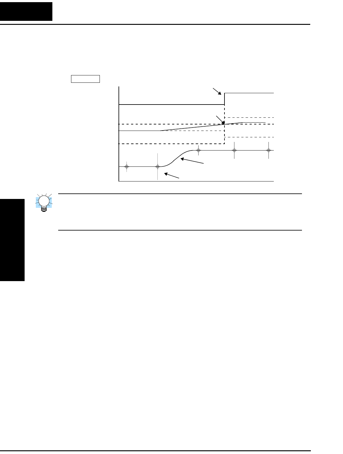
“A” Group: Standard Functions
Configuring
Drive Parameters
3–16
The example graph below shows a typical analog input waveform. The filter removes the
noise spikes. When a speed change (such as level increase) occurs, the filter naturally
has a delayed response. Due to the deadband feature (A016=17), the final output
changes only when the 16-sample average moves past the deadband threshold.
TIP: The deadband feature is useful in applications that require a very stable output
frequency but use an analog input for the speed reference. Example application: A
grinding machine uses a remote potentiometer for operator speed input. After a setting
change, the grinder maintains a very stable speed to deliver a uniform finished surface.
Multi-speed and Jog Frequency Setting
The L2002 inverter has the capability to store and output up to 16 preset frequencies to
the motor (A020 to A035). As in traditional motion terminology, we call this multi-speed
profile capability. These preset frequencies are selected by means of digital inputs to the
inverter. The inverter applies the current acceleration or deceleration setting to change
from the current output frequency to the new one. The first multi-speed setting is dupli-
cated for the second motor settings (the remaining 15 multi-speeds apply only to the first
motor).
The jog speed setting is used whenever the Jog command is active. The jog speed setting
range is arbitrarily limited to 10 Hz, to provide safety during manual operation. The
acceleration to the jog frequency is instantaneous, but you can choose from three modes
for the best method for stopping the jog operation.
Hz
t
“0” Deadband
A016=17
noise spikes
16-sample avg.
+0.1
Output freq.
reference
Analog input
New deadband
speed increase given
–0.2
Threshold exceeded +0.1
“0”
–0.2
Small step-change

L2002 Inverter
Configuring
Drive Parameters
3–17
NOTE: When setting function A039 = 01, the actual jogging deceleration time depends
on the standard Deceleration Time Setting F003/F203.
“A” Function Run
Mode
Edit
Lo Hi
Defaults
Func.
Code
Name /
SRW Display Description –FE(F)
(EU)
–FU
(USA) Units
A020 Multi-speed frequency
setting
Defines the first speed of a
multi-speed profile, range is
0.0 / start frequency to 400 Hz
A020 = Speed 0 (1st motor)
✔ ✔ 0.0 0.0 Hz
SPD 00s 0000.0Hz
A220 Multi-speed frequency
setting, 2nd motor
Defines the first speed of a
multi-speed profile for 2nd
motor, range is 0.0 / start
frequency to 400 Hz
A220 = Speed 0 (2nd motor)
✔ ✔ 0.0 0.0 Hz
2SPD00s 0000.0Hz
A021
to
A035
Multi-speed frequency
settings
(for both motors)
Defines 15 more speeds,
range is 0.0 / start frequency
to 400 Hz.
A021= Speed 1...
A035 = Speed 15
✔ ✔ see
next
row
see
next
row
Hz
SPD 01s 000.0Hz
SPD 02s 000.0Hz
SPD 03s 000.0Hz
SPD 04s 000.0Hz
SPD 05s 000.0Hz
SPD 06s 000.0Hz
SPD 07s 000.0Hz
SPD 08s 000.0Hz
SPD 09s 000.0Hz
SPD 10s 000.0Hz
SPD 11s 000.0Hz
SPD 12s 000.0Hz
SPD 13s 000.0Hz
SPD 14s 000.0Hz
SPD 15s 000.0Hz
A021
A022
A023
A024
A025
A026
A027
A028
A029
A030
A031
A032
A033
A034
A035
0.0
0.0
0.0
0.0
0.0
0.0
0.0
0.0
0.0
0.0
0.0
0.0
0.0
0.0
0.0
0.0
0.0
0.0
0.0
0.0
0.0
0.0
0.0
0.0
0.0
0.0
0.0
0.0
0.0
0.0
A038 Jog frequency setting Defines limited speed for jog,
range is 0.00 / start frequency
to 9.99 Hz
✔ ✔ 1.00 1.00 Hz
Jog-F 001.00Hz
A039 Jog stop mode Define how end of jog stops
the motor; three options:
00 .. Free-run stop
01 .. Controlled deceleration
02 .. DC braking to stop
✘ ✔ 00 00 —
Jog-Mode FRS
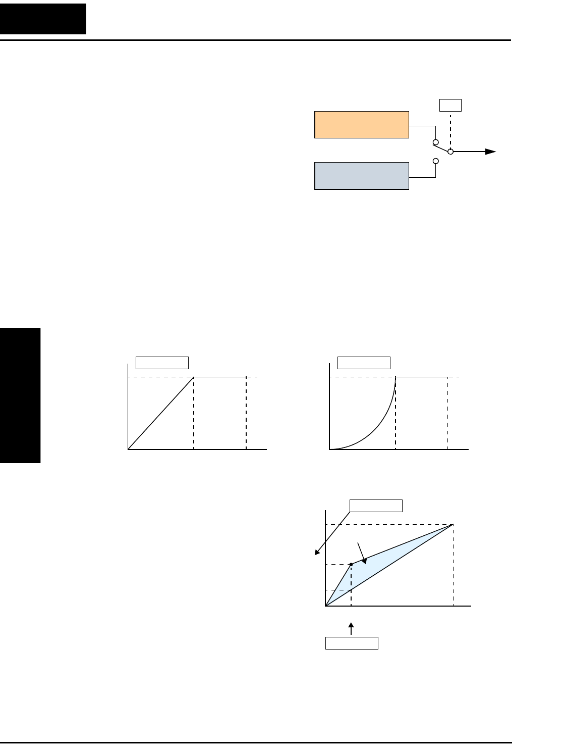
“A” Group: Standard Functions
Configuring
Drive Parameters
3–18
Torque Control Algorithms
The inverter generates the motor output
according to the V/f algorithm selected.
Parameter A044 selects the inverter algorithm
for generating the frequency output, as shown
in the diagram to the right (A244 for 2nd
motor). The factory default is 00 (constant
torque).
Review the following descriptions to help you
choose the best torque control algorithm for
your application.
The built-in V/f curves are oriented toward developing constant torque or variable torque
characteristics (see graphs below). You can select either constant torque or reduced
torque V/f control.
Constant and Variable (Reduced) Torque – The graph below (left) shows the constant
torque characteristic from 0Hz to the base frequency A003. The voltage remains
constant for output frequencies higher than the base frequency. The graph below (right)
shows the general variable (reduced) torque curve. The range from 0Hz to the base
frequency is the variable characteristic.
Manual Torque Boost – The Constant
and Variable Torque algorithms feature an
adjustable torque boost curve. When the
motor load has a lot of inertia or starting
friction, you may need to increase the low
frequency starting torque characteristics
by boosting the voltage above the normal
V/f ratio (shown at right). The function
attempts to compensate for voltage drop in
the motor primary winding in the low
speed range. The boost is applied from
zero to 1/2 the base frequency. You set the
breakpoint of the boost (point A on the
graph) by using parameters A042 and A043. The manual boost is calculated as an
addition to the standard V/f curve.
Output
A44
V/f control,
constant torque
V/f control,
variable torque
00
01
Inverter Torque Control Algorithms
Constant torque
A044 = 00
V
100%
Hz
0
Variable torque
A044 = 01
V
100%
Hz
0
Base
freq.
Max.
freq.
Base
freq.
Max.
freq.
f base =
60Hz
Torque boost
A042 =8
A043 =3(%)
V
Hz
100%
8%
1.8Hz
A
0
(%)
3%
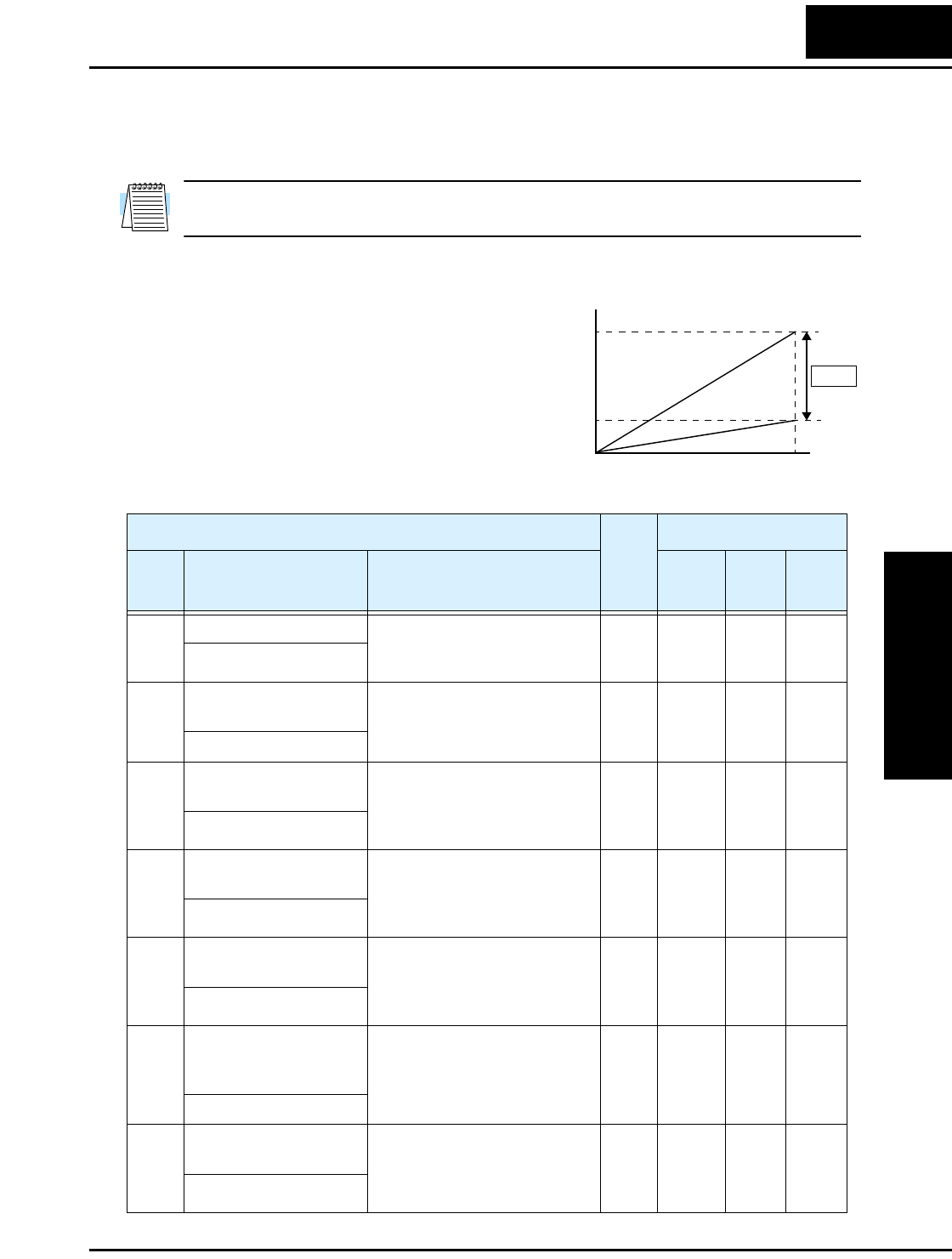
L2002 Inverter
Configuring
Drive Parameters
3–19
Be aware that running the motor at a low speed for a long time can cause motor
overheating. This is particularly true when manual torque boost is ON, or if the motor
relies on a built-in fan for cooling.
NOTE: Manual torque boost applies only to constant torque (A044=00) and variable
torque (A044=01) V/f control.
Voltage Gain – Using parameter A045 you
can modify the voltage gain of the inverter (see
graph at right). This is specified as a percent-
age of the full scale output voltage. The gain
can be set from 20% to 100%. It should be
adjusted in accordance with the motor specifi-
cations.
The following table shows the methods of
torque control selection.
V
1
00%
20%
Hz
Voltage Gain
0
A045
“A” Function Run
Mode
Edit
Lo Hi
Defaults
Func.
Code
Name /
SRW Display Description –FE(F)
(EU)
–FU
(USA) Units
A041 Torque boost select Two options:
00 .. Manual torque boost
01 .. Automatic torque boost
✘ ✘ 00 00 %
V-Bst Slct MN
A241 Torque boost select, 2nd
motor
Two options:
00 .. Manual torque boost
01 .. Automatic torque boost
✘ ✘ 00 00 %
2VBst Slct MN
A042 Manual torque boost
value
Can boost starting torque
between 0 and 20% above
normal V/f curve,
range is 0.0 to 20.0%
✔ ✔ 1.8 1.8 %
V-Bst V 0005.0%
A242 Manual torque boost
value, 2nd motor
Can boost starting torque
between 0 and 20% above
normal V/f curve,
range is 0.0 to 20.0%
✔ ✔ 0.0 0.0 %
2VBst V 0000.0%
A043 Manual torque boost
frequency adjustment
Sets the frequency of the V/f
breakpoint A in graph (top of
previous page) for torque
boost, range is 0.0 to 50.0%
✔ ✔ 10.0 10.0 %
M-Bst F 0003.0%
A243 Manual torque boost
frequency adjustment,
2nd motor
Sets the frequency of the V/f
breakpoint A in graph (top of
previous page) for torque
boost, range is 0.0 to 50.0%
✔ ✔ 0.0 0.0 %
2MBst F 0000.0%
A044 V/f characteristic curve
selection
Two available V/f curves;
three select codes:
00 .. Constant torque
01 .. Reduced torque
✘ ✘ 00 00 —
CTRL C-TRQ

“A” Group: Standard Functions
Configuring
Drive Parameters
3–20
A244 V/f characteristic curve
selection, 2nd motor
Two available V/f curves;
three select codes:
00... Constant torque
01... Reduced torque
✘ ✘ 00 00 —
2CTRL C-TRQ
A045 V/f gain setting Sets voltage gain of the
inverter, range is 20. to 100.%
✔ ✔ 100. 100. %
V-Gain 00100%
A245 V/f gain setting, 2nd
motor
Sets voltage gain of the
inverter, range is 20. to 100.%
✔ ✔ 100. 100. %
2V-Gain 00100%
“A” Function Run
Mode
Edit
Lo Hi
Defaults
Func.
Code
Name /
SRW Display Description –FE(F)
(EU)
–FU
(USA) Units
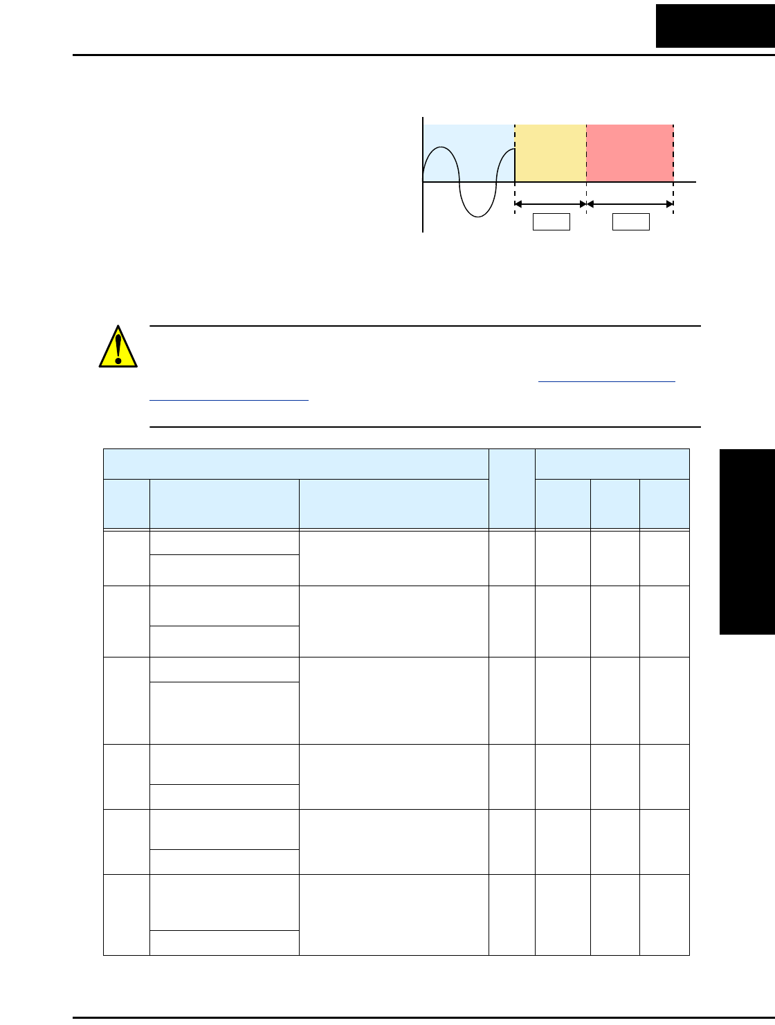
L2002 Inverter
Configuring
Drive Parameters
3–21
DC Braking Settings
The DC braking feature can provide
additional stopping torque when
compared to a normal deceleration to a
stop. DC braking is particularly useful
at low speeds when normal decelera-
tion torque is minimal. When you
enable DC braking, the inverter injects
a DC voltage into the motor windings
during deceleration below a frequency you can specify (A052). The braking power
(A054) and duration (A055) can both be set. You can optionally specify a wait time
before DC braking (A053), during which the motor will free run (coast).
CAUTION: Be careful to avoid specifying a braking time that is long enough to cause
motor overheating. If you use DC braking, we recommend using a motor with a built-in
thermistor, and wiring it to the inverter’s thermistor input (see “Thermistor Thermal
Protection” on page 4–25). Also refer to the motor manufacturer’s specifications for
duty-cycle recommendations during DC braking.
DC brakingFree runRunning
t
0
+
–A053 A055
“A” Function Run
Mode
Edit
Lo Hi
Defaults
Func.
Code
Name /
SRW Display Description –FE(F)
(EU)
–FU
(USA) Units
A051 DC braking enable Two options; select codes:
00 .. Disable
01 .. Enable
✘ ✔ 00 00 —
DCB Mode OFF
A052 DC braking frequency
setting
The frequency at which DC
braking begins,
range is from the start
frequency (B082) to 60 Hz
✘ ✔ 0.5 0.5 Hz
DCB F 0000.5Hz
A053 DC braking wait time The delay from the end of
controlled deceleration to start
of DC braking (motor free runs
until DC braking begins),
range is 0.0 to 5.0 sec.
✘ ✔ 0.0 0.0 sec.
DCB Wait 0000.0s
A054 DC braking force for
deceleration
Level of DC braking force,
settable from 0 to 100%
✘ ✔ 0. 0. %
DCB V 00000%
A055 DC braking time for
deceleration
Sets the duration for DC
braking, range is 0.0 to 60.0
seconds
✘ ✔ 0.0 0.0 sec.
DCB T 0000.0s
A056 DC braking / edge or
level detection for [DB]
input
Two options; select codes:
00 .. Edge detection
01 .. Level detection
✘ ✔ 01 01 —
DCB KIND LEVEL
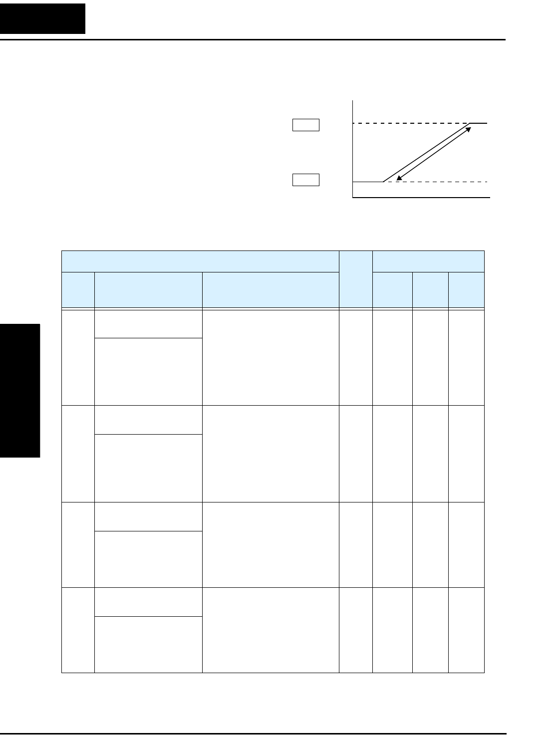
“A” Group: Standard Functions
Configuring
Drive Parameters
3–22
Frequency-related Functions
Frequency Limits – Upper and lower
limits can be imposed on the inverter
output frequency. These limits will apply
regardless of the source of the speed refer-
ence. You can configure the lower
frequency limit to be greater than zero as
shown in the graph. The upper limit must
not exceed the rating of the motor or
capability of the machinery. The
maximum frequency setting (A004/A204)
takes precedence over frequency upper
limit (A061/A261).
Upper
limit
Frequency command
Lower
limit
Settable
range
Output
frequency
0
A061
A062
“A” Function Run
Mode
Edit
Lo Hi
Defaults
Func.
Code
Name /
SRW Display Description –FE(F)
(EU)
–FU
(USA) Units
A061 Frequency upper limit
setting
Sets a limit on output
frequency less than the
maximum frequency (A004).
Range is from frequency lower
limit (A062) to maximum
frequency (A004).
0.0.. setting is disabled
>0.1 setting is enabled
✘ ✔ 0.0 0.0 Hz
Lim H 0000.0Hz
A261 Frequency upper limit
setting, 2nd motor
Sets a limit on output
frequency less than the
maximum frequency (A004).
Range is from frequency lower
limit (A262) to maximum
frequency (A204).
0.0.. setting is disabled
>0.1 setting is enabled
✘ ✔ 0.0 0.0 Hz
2Lim H 0000.0Hz
A062 Frequency lower limit
setting
Sets a limit on output
frequency greater than zero.
Range is start frequency
(B082) to frequency upper
limit (A061).
0.0.. setting is disabled
>0.1 setting is enabled
✘ ✔ 0.0 0.0 Hz
Lim L 0000.0Hz
A262 Frequency lower limit
setting, 2nd motor
Sets a limit on output
frequency greater than zero.
Range is start frequency
(B082) to frequency upper
limit (A261).
0.0.. setting is disabled
>0.1 setting is enabled
✘ ✔ 0.0 0.0 Hz
2Lim L 0000.0Hz
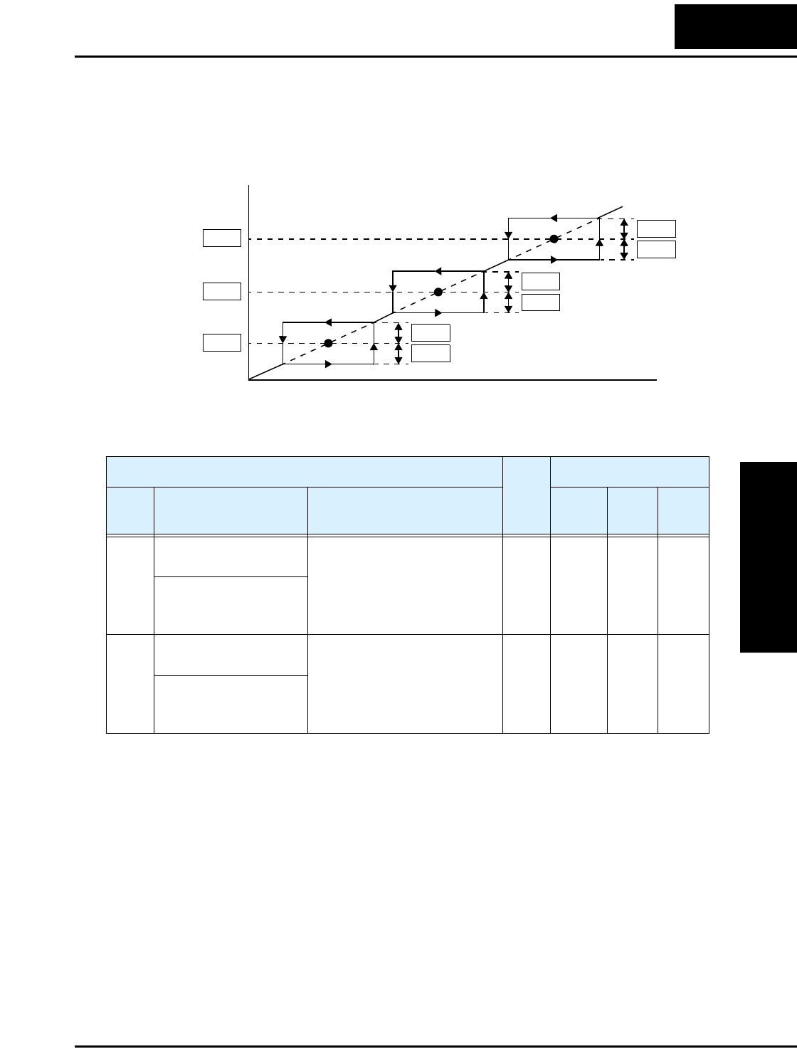
L2002 Inverter
Configuring
Drive Parameters
3–23
Jump Frequencies – Some motors or machines exhibit resonances at particular
speed(s), which can be destructive for prolonged running at those speeds. The inverter
has up to three jump frequencies as shown in the graph. The hysteresis around the jump
frequencies causes the inverter output to skip around the sensitive frequency values.
Jump frequencies
Output
frequency
Frequency command
Hysteresis values
0
A067
A065
A063 A064
A064
A066
A066
A068
A068
“A” Function Run
Mode
Edit
Defaults
Func.
Code
Name /
SRW Display Description –FE(F)
(EU)
–FU
(USA) Units
A063,
A065,
A067
Jump (center) frequency
setting
Up to 3 output frequencies can
be defined for the output to
jump past to avoid motor
resonances (center frequency)
Range is 0.0 to 400.0 Hz
✘ ✔ 0.0
0.0
0.0
0.0
0.0
0.0
Hz
JUMP F1 0000.0Hz
JUMP F2 0000.0Hz
JUMP F3 0000.0Hz
A064,
A066,
A068
Jump (hysteresis)
frequency width setting
Defines the distance from the
center frequency at which the
jump around occurs
Range is 0.0 to 10.0 Hz
✘ ✔ 0.5
0.5
0.5
0.5
0.5
0.5
Hz
JUMP W1 0000.5Hz
JUMP W2 0000.5Hz
JUMP W3 0000.5Hz

“A” Group: Standard Functions
Configuring
Drive Parameters
3–24
PID Control
When enabled, the built-in PID loop calculates an ideal inverter output value to cause a
loop feedback process variable (PV) to move closer in value to the setpoint (SP). The
frequency command serves as the SP. The PID loop algorithm will read the analog input
for the process variable (you specify the current or voltage input) and calculate the
output.
• A scale factor in A075 lets you multiply the PV by a factor, converting it into
engineering units for the process.
• Proportional, integral, and derivative gains are all adjustable.
•See “PID Loop Operation” on page 4–56 for more information.
NOTE: The setting A073 for the integrator is the integrator’s time constant Ti, not the
gain. The integrator gain Ki = 1/Ti. When you set A073 = 0, the integrator is disabled.
“A” Function Run
Mode
Edit
Lo Hi
Defaults
Func.
Code
Name /
SRW Display Description –FE(F)
(EU)
–FU
(USA) Units
A071 PID Enable Enables PID function,
two option codes:
00... PID Disable
01... PID Enable
✘ ✔ 00 00 —
PID Mode OFF
A072 PID proportional gain Proportional gain has a range
of 0.2 to 5.0
✔ ✔ 1.0 1.0 —
PID P 0001.0
A073 PID integral time
constant
Integral time constant has a
range of 0.0 to 150 seconds
✔ ✔ 1.0 1.0 sec.
PID I 0001.0s
A074 PID derivative time
constant
Derivative time constant has a
range of 0.0 to 100 seconds
✔ ✔ 0.0 0.0 sec.
PID D 000.00s
A075 PV scale conversion Process Variable (PV) scale
factor (multiplier), range of
0.01 to 99.99
✘ ✔ 1.00 1.00 —
PID Cnv 001.00%
A076 PV source setting Selects source of Process
Variable (PV), option codes:
00... [OI] terminal (current in)
01... [O] terminal (voltage in)
02... ModBus network
03... Calculate function output
✘ ✔ 00 00 —
PID INP OI
A077 Reverse PID action Two option codes:
00... PID input = SP – PV
01... PID input = –(SP – PV)
✘ ✔ 00 00 —
PID MINUS OFF
A078 PID output limit Sets the limit of PID output as
percent of full scale,
range is 0.0 to 100.0%
✘ ✔ 0.0 0.0 %
PID Vari 0000.0%

L2002 Inverter
Configuring
Drive Parameters
3–25
Automatic Voltage Regulation (AVR) Function
The automatic voltage regulation (AVR) feature keeps the inverter output waveform at a
relatively constant amplitude during power input fluctuations. This can be useful if the
installation is subject to input voltage fluctuations. However, the inverter cannot boost its
motor output to a voltage higher than the power input voltage. If you enable this feature,
be sure to select the proper voltage class setting for your motor.
“A” Function Run
Mode
Edit
Lo Hi
Defaults
Func.
Code
Name /
SRW Display Description –FE(F)
(EU)
–FU
(USA) Units
A081 AVR function select Automatic (output) voltage
regulation, selects from three
type of AVR functions, three
option codes:
00 .. AVR enabled
01 .. AVR disabled
02 .. AVR enabled except
during deceleration
✘ ✘ 00 00 —
AVR Mode ON
A082 AVR voltage select 200V class inverter settings:
...... 200/215/220/230/240
400V class inverter settings:
...... 380/400/415/440/460/480
✘ ✘ 230/
400
230/
460
V
AVR AC 00230V
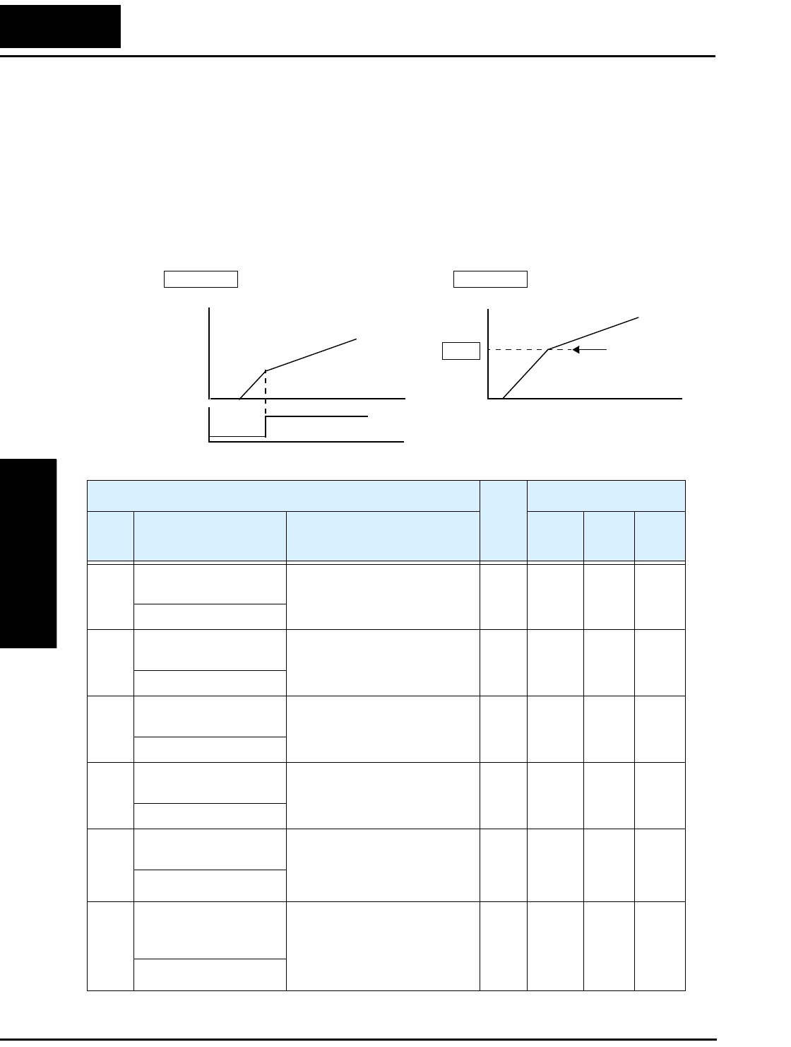
“A” Group: Standard Functions
Configuring
Drive Parameters
3–26
Second Acceleration and Deceleration Functions
The L2002 inverter features two-stage acceleration and deceleration ramps. This gives
flexibility in the profile shape. You can specify the frequency transition point, the point
at which the standard acceleration (F002) or deceleration (F003) changes to the second
acceleration (A092) or deceleration (A093). Or, you can use intelligent input [2CH] to
trigger this transition. These profile options are also available for the second motor
settings. Select a transition method via A094 as depicted below. Be careful not to
confuse the second acceleration/deceleration settings with settings for the second
motor!
Accel 1
Accel 2
2CH
input
Frequency
transition point
A95
A094 =00 A094 =01
Output
frequency
Output
frequency
t
t
Accel 1
Accel 2
t
Transition via 2CH input Transition via freq. level
00
1
0
“A” Function Run
Mode
Edit
Lo Hi
Defaults
Func.
Code
Name /
SRW Display Description –FE(F)
(EU)
–FU
(USA) Units
A092 Acceleration (2) time
setting
Duration of 2nd segment of
acceleration, range is:
0.01 to 3000 sec.
✔ ✔ 15.00 15.00 sec.
ACC 2 0015.00s
A292 Acceleration (2) time
setting, (2nd motor)
Duration of 2nd segment of
acceleration, 2nd motor,
range is: 0.01 to 3000 sec.
✔ ✔ 15.00 15.00 sec.
2ACC2 015.00s
A093 Deceleration (2) time
setting
Duration of 2nd segment of
deceleration, range is:
0.01 to 3000 sec.
✔ ✔ 15.00 15.00 sec.
DEC 2 015.00s
A293 Deceleration (2) time
setting, (2nd motor)
Duration of 2nd segment of
deceleration, 2nd motor,
range is: 0.01 to 3000 sec.
✔ ✔ 15.00 15.00 sec.
2DEC2 015.00s
A094 Select method to switch
to Acc2/Dec2 profile
Two options for switching
from 1st to 2nd accel/decel:
00... 2CH input from terminal
01... transition frequency
✘ ✘ 00 00 —
ACC CHG TM
A294 Select method to switch
to Acc2/Dec2 profile,
2nd motor
Two options for switching
from 1st to 2nd accel/decel:
00... 2CH input from terminal
01... transition frequency
(2nd motor)
✘ ✘ 00 00 —
2ACCCHG TM
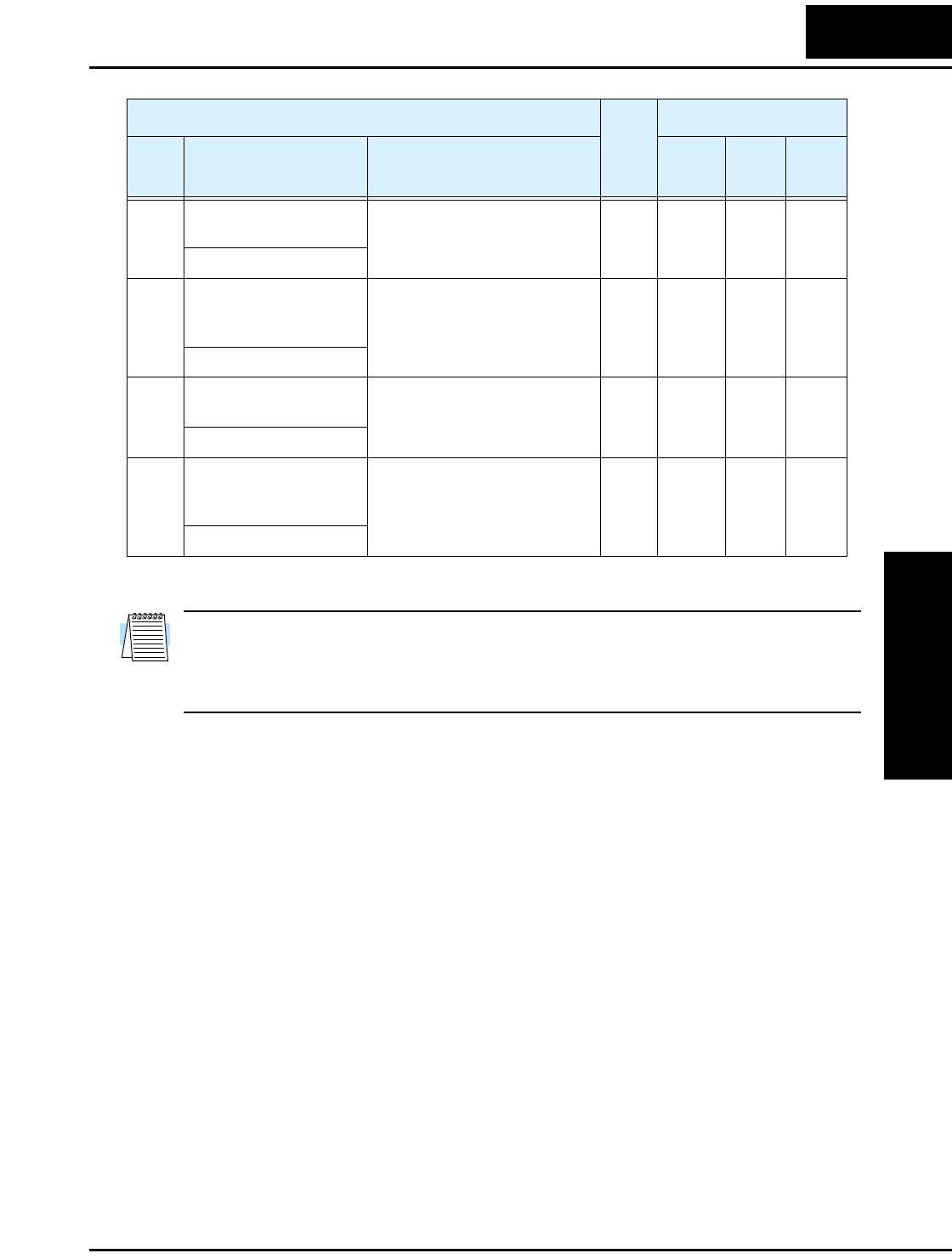
L2002 Inverter
Configuring
Drive Parameters
3–27
NOTE: For A095 and A096 (and for 2nd motor settings), if you set a very rapid Acc1 or
Dec1 time (less than 1.0 second), the inverter may not be able to change rates to Acc2 or
Dec2 before reaching the target frequency. In that case, the inverter decreases the rate of
Acc1 or Dec1 in order to achieve the second ramp to the target frequency.
A095 Acc1 to Acc2 frequency
transition point
Output frequency at which
Accel1 switches to Accel2,
range is 0.0 to 400.0 Hz
✘ ✘ 0.0 0.0 Hz
ACC CHfr0000.0Hz
A295 Acc1 to Acc2 frequency
transition point, 2nd
motor
Output frequency at which
Accel1 switches to Accel2,
range is 0.0 to 400.0 Hz
✘ ✘ 0.0 0.0 Hz
2ACCCHfr0000.0Hz
A096 Dec1 to Dec2 frequency
transition point
Output frequency at which
Decel1 switches to Decel2,
range is 0.0 to 400.0 Hz
✘ ✘ 0.0 0.0 Hz
DEC CHfr0000.0Hz
A296 Dec1 to Dec2 frequency
transition point, 2nd
motor
Output frequency at which
Decel1 switches to Decel2,
range is 0.0 to 400.0 Hz
✘ ✘ 0.0 0.0 Hz
2DECCHfr0000.0Hz
“A” Function Run
Mode
Edit
Lo Hi
Defaults
Func.
Code
Name /
SRW Display Description –FE(F)
(EU)
–FU
(USA) Units
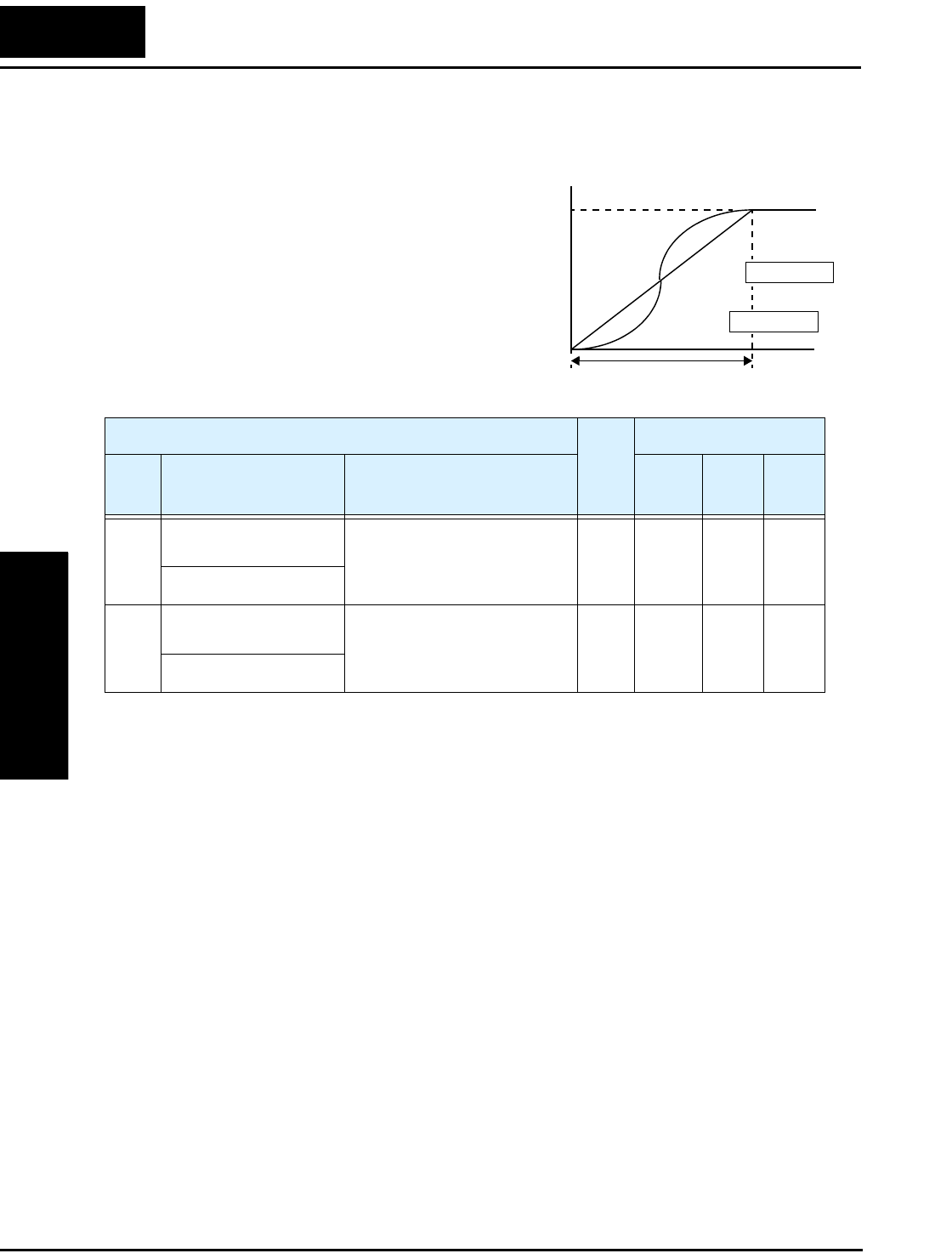
“A” Group: Standard Functions
Configuring
Drive Parameters
3–28
Accel/Decel
Standard acceleration and deceleration is
linear. The inverter CPU can also calculate
an S-curve acceleration or deceleration
curve as shown. This profile is useful for
favoring the load characteristics in particu-
lar applications.
Curve settings for acceleration and decel-
eration are independently selected. To
enable the S-curve, use function A097
(acceleration) and A098 (deceleration).
Acceleration period
S-curve
Linear
Accel. curve selection
Target
freq.
Output
frequency
t
0
A097 =00
A097 =01
“A” Function Run
Mode
Edit
Lo Hi
Defaults
Func.
Code
Name /
SRW Display Description –FE(F)
(EU)
–FU
(USA) Units
A097 Acceleration curve
selection
Set the characteristic curve of
Acc1 and Acc2, two options:
00... linear
01... S-curve
✘ ✘ 00 00 —
ACC LINE L
A098 Deceleration curve
selection
Set the characteristic curve of
Acc1 and Acc2, two options:
00... linear
01... S-curve
✘ ✘ 00 00 —
DEC LINE L

L2002 Inverter
Configuring
Drive Parameters
3–29
Additional Analog Input Settings
Input Range Settings – The parameters in the following table adjust the input charac-
teristics of the analog current input. When using the inputs to command the inverter
output frequency, these parameters adjust the starting and ending ranges for the current,
as well as the output frequency range. Related characteristic diagrams are located in
“Analog Input Settings” on page 3–14.
“A” Function Run
Mode
Edit
Lo Hi
Defaults
Func.
Code
Name /
SRW Display Description –FE(F)
(EU)
–FU
(USA) Units
A101 [OI]–[L] input active
range start frequency
The output frequency corre-
sponding to the current input
range starting point.
Range is 0.00 to 400.0 Hz
✘ ✔ 0.0 0.0 Hz
OI-EXS 0000.0Hz
A102 [OI]–[L] input active
range end frequency
The output frequency corre-
sponding to the current input
range ending point.
Range is 0.00 to 400.0 Hz
✘ ✔ 0.0 0.0 Hz
OI-EXE 0000.0Hz
A103 [OI]–[L] input active
range start current
The starting point for the
current input range.
Range is 0. to 100.%
✘ ✔ 0.0 0.0 %
OI-EX%S 00000%
A104 [OI]–[L] input active
range end current
The ending point for the
current input range.
Range is 0. to 100.%
✘ ✔ 100. 100. %
OI-EX%E 00100%
A105 [OI]–[L] input start
frequency enable
Two options:
00 .. Use A101 start value
01 .. Use 0Hz
✘ ✔ 01 01 —
OI-LVL 0Hz
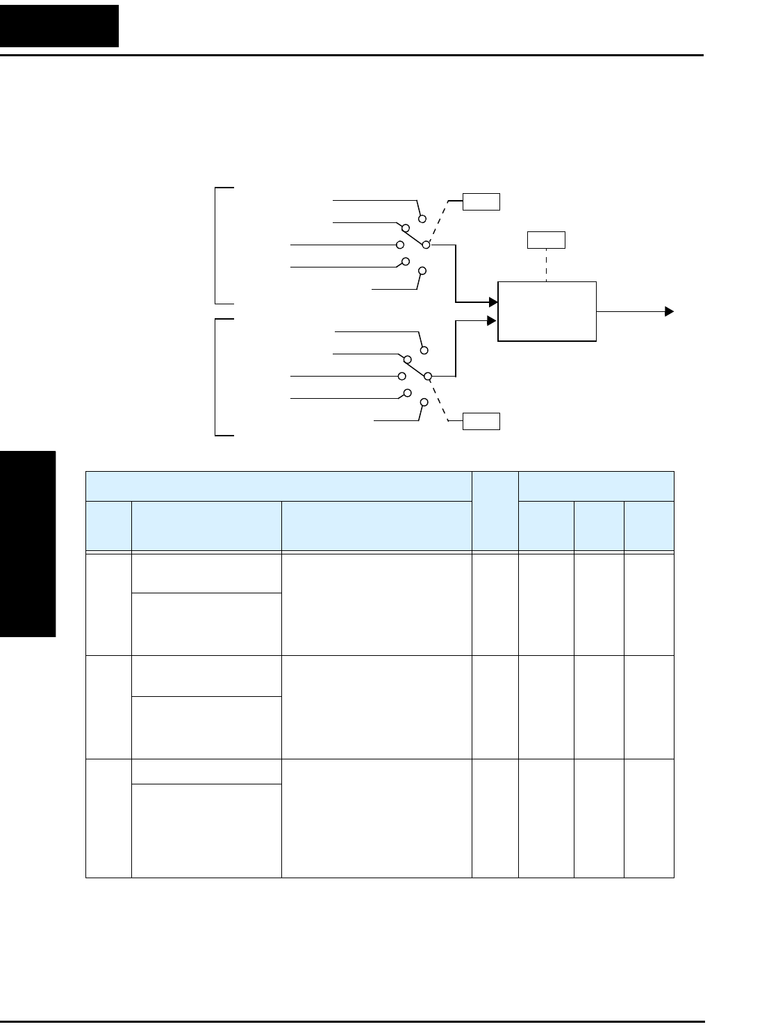
“A” Group: Standard Functions
Configuring
Drive Parameters
3–30
Analog Input Calculate Function – The inverter can mathematically combine two
input sources into one value. The Calculate function can either add, subtract, or multiply
the two selected sources. This provides the flexibility needed by various applica-
tions.You can use the result for the output frequency setting (use A001=10) or for the
PID Process Variable (PV) input (use A075=03).
A141
[O] input
Potentiometer
[OI] input
Network variable F001
Digital operator
[O] input
Potentiometer
[OI] input
Network variable F001
Digital operator
A142
A input
select
A143
• 00 A + B
• 01 A – B
• 02 A x B
A
B
“CAL”
(result)
B input
select
“A” Function Run
Mode
Edit
Lo Hi
Defaults
Func.
Code
Name /
SRW Display Description –FE(F)
(EU)
–FU
(USA) Units
A141 A input select for
calculate function
Five options:
00... Digital operator
01... Keypad potentiometer
02... [O] input
03... [OI] input
04... Network variable
✘ ✔ 02 02 —
CALC Slct1 O
A142 B input select for
calculate function
Five options:
00... Digital operator
01... Keypad potentiometer
02... [O] input
03... [OI] input
04... Network variable
✘ ✔ 03 03 —
CALC Slct2 OI
A143 Calculation symbol Calculates a value based on the
A input source (A141 selects)
and the B input source (A142
selects). Three options:
00... ADD (A input + B input)
01... SUB (A input – B input)
02... MUL (A input x B input)
✘ ✔ 00 00 —
CALC SMBL ADD
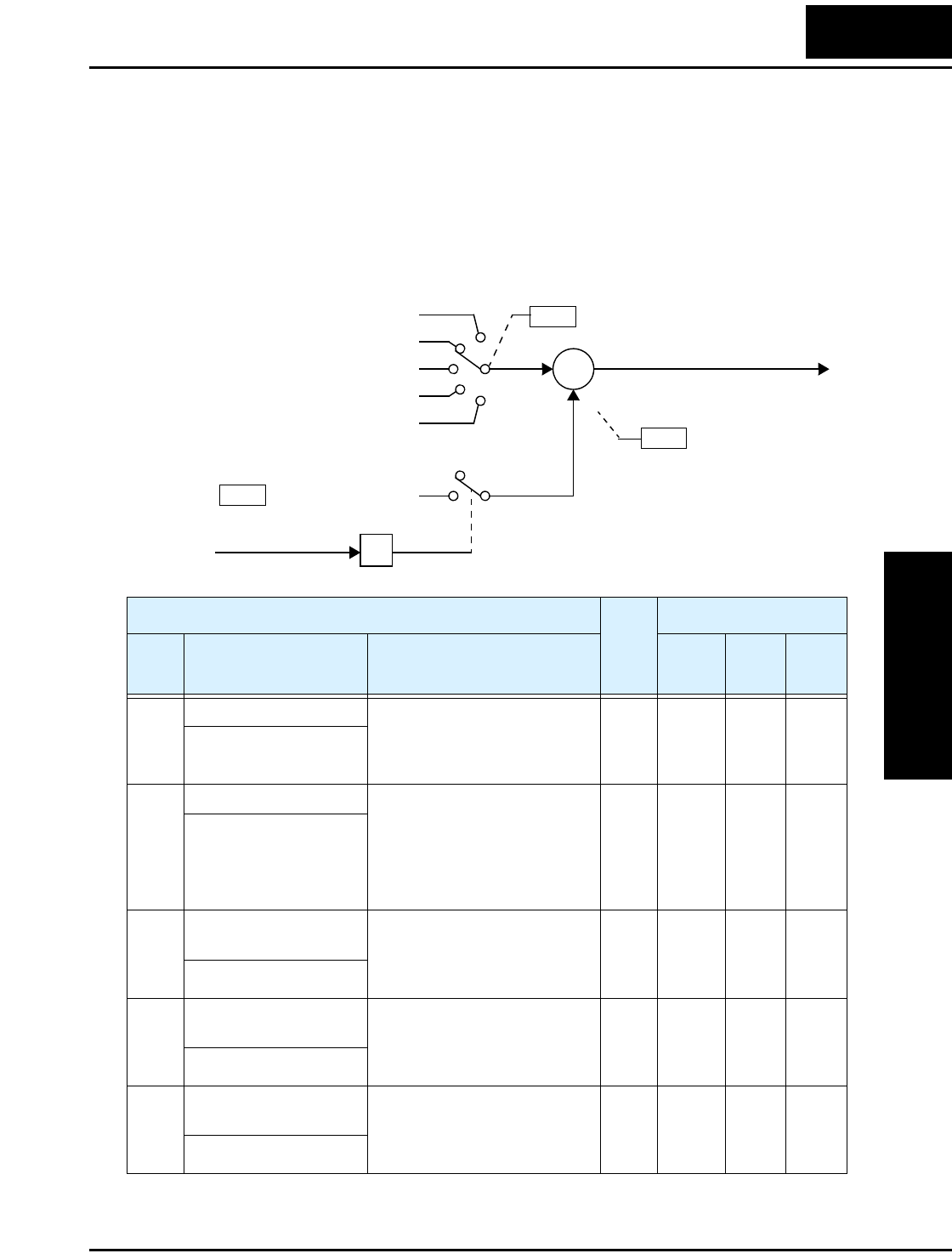
L2002 Inverter
Configuring
Drive Parameters
3–31
ADD Frequency – The inverter can add or subtract an offset value to the output
frequency setting which is specified by A001 (will work with any of the five possible
sources). The ADD Frequency is a value you can store in parameter A145. The ADD
Frequency is summed with or subtracted from the output frequency setting only when
the [ADD] terminal is ON. Function A146 selects whether to add or subtract. By config-
uring an intelligent input as the [ADD] terminal, your application can selectively apply
the fixed value in A145 to offset (positively or negatively) the inverter output frequency
in real time.
A001
Function F001 setting
Control terminal
Network variable F001
Calculate function output
Keypad potentiometer
A145
+
∑
+/–
ADD frequency
Frequency source setting
Output frequency setting
[ADD]Intelligent input
A146 ADD direction select
“A” Function Run
Mode
Edit
Lo Hi
Defaults
Func.
Code
Name /
SRW Display Description –FE(F)
(EU)
–FU
(USA) Units
A145 ADD frequency An offset value that is applied
to the output frequency when
the [ADD] terminal is ON.
Range is 0.0 to 400.0 Hz
✔ ✔ 0.0 0.0 Hz
ST-PNT 0000.0Hz
A146 ADD direction select Two options:
00 .. Plus (adds A145 value to
the output frequency setting)
01 .. Minus (subtracts A145
value from the output
frequency setting)
✘ ✔ 00 00 —
ADD DIR PLUS
A151 Pot. input active range
start frequency
The output frequency corre-
sponding to the potentiometer
range starting point,
range is 0.0 to 400.0
✘ ✔ 0.0 0.0 Hz
POT EXS 0.0
A152 Pot. input active range
end frequency
The output frequency corre-
sponding to the potentiometer
range ending point,
range is 0.0 to 400.0
✘ ✔ 0.0 0.0 Hz
POT EXE 0.0
A153 Pot. input active range
start current
The output frequency corre-
sponding to the potentiometer
range starting point,
range is 0.0 to 100.0
✘ ✔ 0.0 0.0 %
POT EX%S 0.0

“A” Group: Standard Functions
Configuring
Drive Parameters
3–32
A154 Pot. input active range
end current
The output frequency corre-
sponding to the potentiometer
range ending point,
range is 0.0 to 100.0
✘ ✔ 0.0 0.0 %
POT EXS%E 0.0
A155 Pot. input start
frequency enable
Two options:
00... Disable
01... Enable
✘ ✔ 01 01 —
POT LVL 01
“A” Function Run
Mode
Edit
Lo Hi
Defaults
Func.
Code
Name /
SRW Display Description –FE(F)
(EU)
–FU
(USA) Units
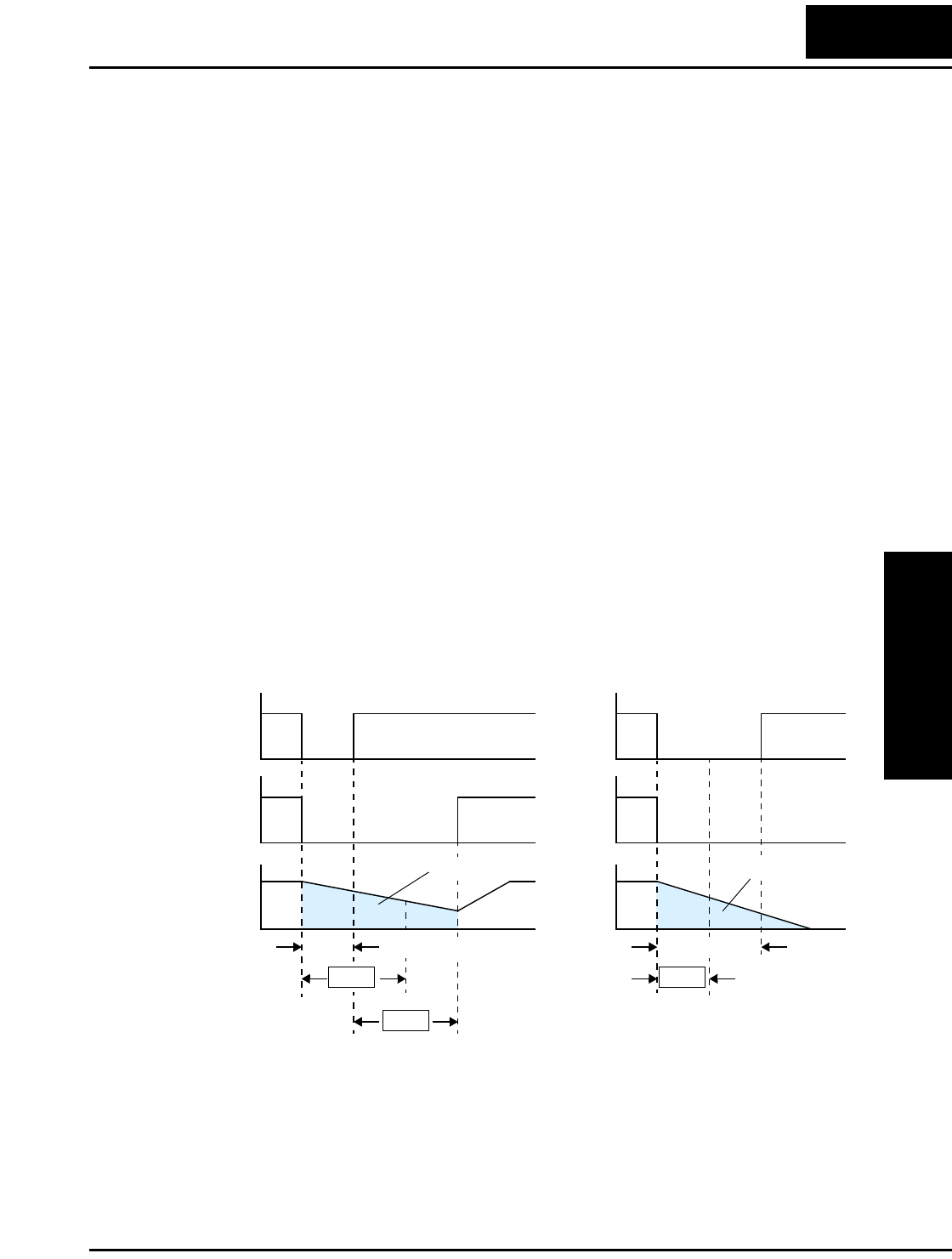
L2002 Inverter
Configuring
Drive Parameters
3–33
“B” Group: Fine Tuning Functions
The “B” Group of functions and parameters adjust some of the more subtle but useful
aspects of motor control and system configuration.
Automatic Restart Mode
The restart mode determines how the inverter will resume operation after a fault causes a
trip event. The four options provide advantages for various situations. Frequency
matching allows the inverter to read the motor speed by virtue of its residual magnetic
flux and restart the output at the corresponding frequency. The inverter can attempt a
restart a certain number of times depending on the particular trip event:
• Over-current trip, restart up to 3 times
• Over-voltage trip, restart up to 3 times
• Under-voltage trip, restart up to 16 times
When the inverter reaches the maximum number of restarts (3 or 16), you must power
cycle the inverter to reset its operation.
Other parameters specify the allowable under-voltage level and the delay time before
restarting. The proper settings depend on the typical fault conditions for your applica-
tion, the necessity of restarting the process in unattended situations, and whether restart-
ing is always safe.
Input
power
Motor
speed
Power fail t
0
0
Power failure < allowable power fail
time (B002), inverter resumes
0
Inverter
output
free-running
Input
power
Motor
speed
t
0
0
Power failure > allowable power fail
time (B002), inverter trips
0
Inverter
output
free-running
Allowable
power fail time
Retry wait time
Power fail
Allowable
power fail time
B002 B002
B003

“B” Group: Fine Tuning Functions
Configuring
Drive Parameters
3–34
Instantaneous Power Failure / Under-voltage Alarm
Use parameter B004 to disable or enable the instantaneous power failure / undervoltage
alarm. When the alarm is enabled, parameter settings B001 (Selection of Automatic
Restart Mode) and B002 (Allowable Under-voltage Power Failure Time) are not valid.
“B” Function Run
Mode
Edit
Lo Hi
Defaults
Func.
Code
Name /
SRW Display Description –FE(F)
(EU)
–FU
(USA) Units
B001 Selection of automatic
restart mode
Select inverter restart method,
four option codes:
00... Alarm output after trip,
no automatic restart
01... Restart at 0Hz
02... Resume operation after
frequency matching
03... Resume previous freq.
after freq. matching, then
decelerate to stop and display
trip info.
✘ ✔ 00 00 —
IPS POWR ALM
B002 Allowable under-
voltage power failure
time
The amount of time a power
input under-voltage can occur
without tripping the power
failure alarm. Range is 0.3 to
25 sec. If under-voltage exists
longer than this time, the
inverter trips, even if the restart
mode is selected.
✘ ✔ 1.0 1.0 sec.
IPS Time 0001.0s
B003 Retry wait time before
motor restart
Time delay after under-voltage
condition goes away, before
the inverter runs motor again.
Range is 0.3 to 100 seconds.
✘ ✔ 1.0 1.0 sec.
IPS Wait 0001.0s
B004 Instantaneous power
failure / under-voltage
trip alarm enable
Two option codes:
00... Disable
01... Enable
✘ ✔ 00 00 sec.
IPS TRIP OFF
B005 Number of restarts on
power failure / under-
voltage trip events
Two option codes:
00... Restart 16 times
01... Always restart
✘ ✔ 00 00 sec.
IPS RETRY 16
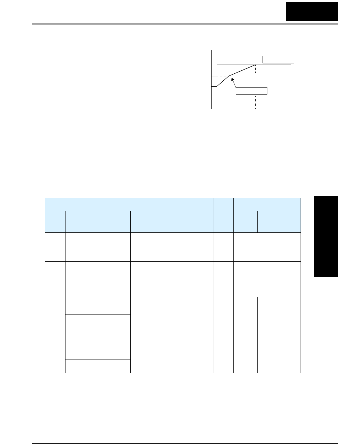
L2002 Inverter
Configuring
Drive Parameters
3–35
Electronic Thermal Overload Alarm Setting
The thermal overload detection protects the
inverter and motor from overheating due to
an excessive load. It uses a current/inverse
time curve to determine the trip point.
First, use B013 to select the torque charac-
teristic that matches your load. This allows
the inverter to utilize the best thermal
overload characteristic for your application.
The torque developed in a motor is directly
proportional to the current in the windings,
which is also proportional to the heat generated (and temperature, over time). Therefore,
you must set the thermal overload threshold in terms of current (amperes) for parameter
B012. The range is 20% to 120% of the rated current for each inverter model. If the
current exceeds the level you specify, the inverter will trip and log an event (error E05) in
the history table. The inverter turns the motor output OFF when tripped. Separate
settings are available for the second motor (if applicable) as shown in the following
table.
Output frequency
Constant torque
Reduced
torque
B013 =01
B013 =00
To r q u e
520 60 120
Hz
100%
80%
60%
0
“B” Function Run
Mode
Edit
Lo Hi
Defaults
Func.
Code
Name /
SRW Display Description –FE(F)
(EU)
–FU
(USA) Units
B012 Level of electronic
thermal setting
Set a level between 20% and
120% for the rated inverter
current.
✘ ✔ Rated current
for each inverter
model *1
A
E-THM LVL001.60A
B212 Level of electronic
thermal setting, 2nd
motor
Set a level between 20% and
120% for the rated inverter
current.
✘ ✔ Rated current
for each inverter
model *1
A
2ETHM LVL 01.60A
B013 Electronic thermal
characteristic
Select from two curves, option
codes:
00 .. Reduced torque 1
01 .. Constant torque
02 .. Reduced torque 2
✘ ✔ 01 01 —
E-THM CHAR CRT
B213 Electronic thermal
characteristic, 2nd
motor
Select from two curves, option
codes:
00 .. Reduced torque 1
01 .. Constant torque
02 .. Reduced torque 2
✘ ✔ 01 01 —
2ETHM CHAR CRT
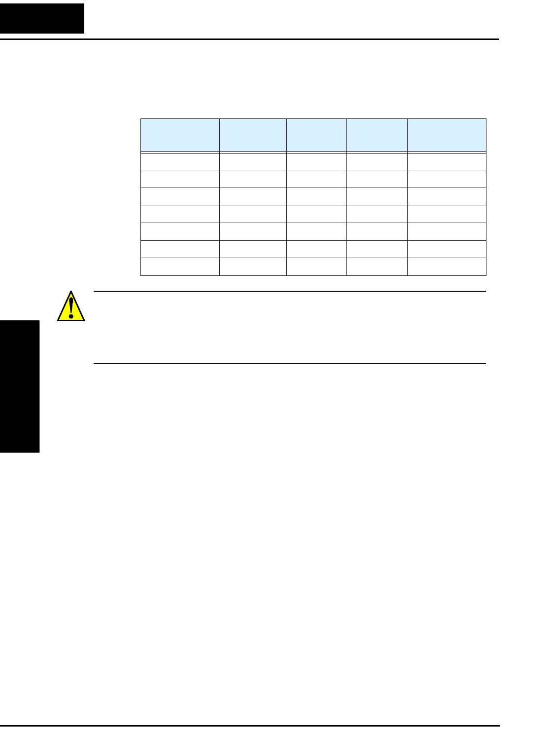
“B” Group: Fine Tuning Functions
Configuring
Drive Parameters
3–36
Note 1: For inverter models 005NFE(F), 011NFE(F), and 030HFE(F), the overload-
related parameter settings are different from the rated amperes. Therefore, be
sure to set the electronic thermal overload according to the actual motor
driven by the particular inverter.
WARNING: When parameter B012, level of electronic thermal setting, is set to motor
FLA rating (Full Load Ampere nameplate rating), the inverter provides solid state motor
overload protection at 115% of motor FLA or equivalent. If parameter B012 exceeds the
motor FLA rating, the motor may overheat and be damaged. Parameter B012, level of
electronic thermal setting, is a variable parameter.
Inverter Model B012/B212
(A)
B022
(A)
C041
(A)
Inverter rated
Amperes (A)
–004NFE(F) 2.60 3.90 2.60 2.60
–005NFE(F) 4.00 6.00 4.00 3.00
–007NFE(F) 4.00 6.00 4.00 4.00
–0011NFE(F) 7.10 10.65 7.10 5.00
–015NFE(F) 7.10 10.65 7.10 7.10
–030NFE(F) 8.60 12.90 8.60 7.80
–040NFE(F) 8.60 12.90 8.60 8.60
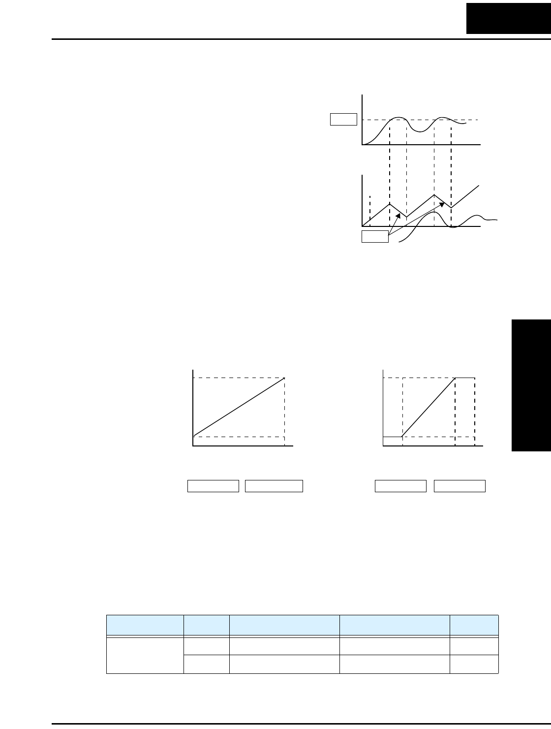
L2002 Inverter
Configuring
Drive Parameters
3–37
Overload Restriction
If the inverter’s output current exceeds a
preset current level you specify during
acceleration or constant speed, the overload
restriction feature automatically reduces the
output frequency to restrict the overload.
This feature does not generate an alarm or
trip event. You can instruct the inverter to
apply overload restriction only during
constant speed, thus allowing higher
currents for acceleration. Or, you may use
the same threshold for both acceleration and
constant speed.
When the inverter detects an overload, it
must decelerate the motor to reduce the current until it is less than the threshold. You can
choose the rate of deceleration that the inverter uses to lower the output current.
The overload restriction level can be set to a constant or to a variable (analog input). For
constant values, use B028/B228 = 00 to select parameters B022/B222. For a variable
overload restriction level, use B028/B228 = 01 to select analog voltage input terminals
[O]–[L]. In this case, parameters A013 and A014 set the start and end points for the
linear range of the graph as shown in the graphs below.
When using the analog input method to set the overload restriction (B028/B228 = 01),
the inverter does not read settings B022/B222 Overload Restriction Level. Instead, the
inverter writes the analog input value (in Ampere units) to parameters B022/B222. In
this way, you can monitor the effective overload restriction value (in Amperes) in real
time. However, you cannot store the value to B022/B222. If you use the second motor
function, the inverter displays “void” for either B022 or B222 if the parameter’s corre-
sponding motor is not selected via Set or Special Set functions.
Input State B022 monitor display B222 monitor display Units
[SET] or [S-ST]
OFF [O] analog input value void A
ON void [O] analog input value A
Motor
Current
Output
frequency
t
t
Restriction area
0
0
B022
B023
Overload
restriction
level
[O]–[L] input
10%
150%
0V 10V
10%
150%
0V 10V
Overload
restriction
level
[O]–[L] input
A013 =0A014 =100 A013 =20 A014 =80
28

“B” Group: Fine Tuning Functions
Configuring
Drive Parameters
3–38
“B” Function Run
Mode
Edit
Lo Hi
Defaults
Func.
Code
Name /
SRW Display Description –FE(F)
(EU)
–FU
(USA) Units
B021 Overload restriction
operation mode
Select the operating mode
during overload conditions,
three options, option codes:
00... Disabled
01... Enabled for acceleration
and constant speed
02... Enabled for constant
speed only
✘ ✔ 01 01 —
OL Mode ON
B221 Overload restriction
operation mode, 2nd
motor
✘ ✔ 01 01 —
2OL Mode ON
B022 Overload restriction
setting
Sets the level for overload
restriction, between 10% and
150% of the rated current of
the inverter, setting resolution
is 1% of rated current. This
parameter monitors (read-only)
the [O]–[L] input when that
input is the overload restriction
source (B028/B228 = 01).
✘ ✔ Rated current x
1.5
A
OL LVL 002.40A
B222 Overload restriction
setting, 2nd motor
✘ ✔ Rated current x
1.5
A
2OL LVL 002.40A
B023 Deceleration rate at
overload restriction
Sets the deceleration rate when
inverter detects overload, range
is 0.1 to 30.0, resolution is 0.1.
✘ ✔ 1.0 30.0 sec.
OL Cnst 0001.0s
B223 Deceleration rate at
overload restriction,
2nd motor
Sets the deceleration rate when
inverter detects overload, range
is 0.1 to 30.0, resolution is 0.1.
✘ ✔ 1.0 30.0 sec.
2OL Cnst 0001.0s
B028 Overload restriction
source selection
Two options; select codes:
00... B022/B222 setting level
01... [O]–[L] analog input
✘ ✔ 00 00 sec.
OL L-Slct C022
B228 Overload restriction
source selection, 2nd
motor
Two options; select codes:
00... B022/B222 setting level
01... [O]–[L] analog input
✘ ✔ 00 00 sec.
2OL L-Slct C022
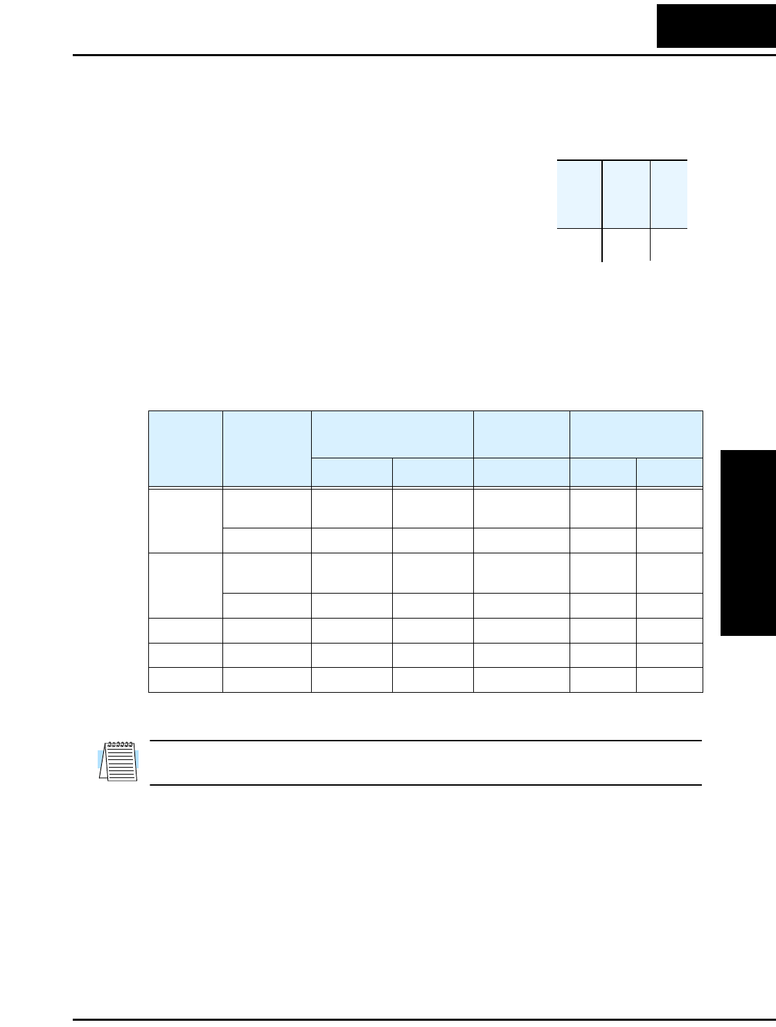
L2002 Inverter
Configuring
Drive Parameters
3–39
Software Lock Mode
The software lock function keeps personnel from accidentally changing parameters in
the inverter memory. Use B031 to select from various protection levels.
The table below lists all combinations of B031 option codes
and the ON/OFF state of the [SFT] input. Each Check ✔ or Ex
✘ indicates whether the corresponding parameter(s) can be
edited. The Standard Parameters column below lists Low and
High level access for some lock modes. These refer to the
parameter tables throughout this chapter, each of which
includes a column titled Run Mode Edit as shown to the right.
The two marks (Check ✔ or Ex ✘) under the “Lo Hi” subtitle indicate whether
Low-level and/or High-level access applies to each parameter as defined in the table
below. In some lock modes, you can edit only F001 and the Multi-speed parameter group
that includes A020, A220, A021–A035, and A038 (Jog). However, it does not include
A019, Multi-speed operation selection. The editing access to B031 itself is unique, and
is specified in the right-most two columns below.
NOTE: Since the software lock function B031 is always accessible, this feature is not
the same as password protection used in other industrial control devices.
B031
Lock
Mode
[SFT]
Intelligent
Input
Standard Parameters F001 and
Multi-Speed B031
Stop Run Stop & Run Stop Run
00 OFF ✔Run mode
edit access
✔✔✘
ON ✘✘ ✘✔✘
01 OFF ✔Run mode
edit access
✔✔✘
ON ✘✘ ✔✔✘
02 (ignored) ✘✘ ✘✔✘
03 (ignored) ✘✘ ✔✔✘
10 (ignored) ✔High-level ✔✔✔
Run
Mode
Edit
Lo Hi
✘ ✔

“B” Group: Fine Tuning Functions
Configuring
Drive Parameters
3–40
NOTE: To disable parameter editing when using B031 lock modes 00 and 01, assign the
[SFT] function to one of the intelligent input terminals.
See “Software Lock” on page 4–22.
“B” Function Run
Mode
Edit
Lo Hi
Defaults
Func.
Code
Name /
SRW Display Description –FE(F)
(EU)
–FU
(USA) Units
B031 Software lock mode
selection
Prevents parameter changes, in
five options, option codes:
00... Low-level access, [SFT]
input blocks all edits
01... Low-level access, [SFT]
input blocks edits (except F001
and Multi-speed parameters)
02... No access to edits
03... No access to edits except
F001 and Multi-speed parame-
ters
10... High-level access, includ-
ing B031
✘ ✔ 01 01 —
S-Lock MD1

L2002 Inverter
Configuring
Drive Parameters
3–41
Miscellaneous Settings
The miscellaneous settings include scaling factors, initialization modes, and others. This
section covers some of the most important settings you may need to configure.
B080: [AM] analog signal gain – This parameter allows you to scale the analog output
[AM] relative to the monitored variable.
B082: Start frequency adjustment – When the inverter starts to run, the output
frequency does not ramp from 0Hz. Instead, it steps directly to the start frequency
(B082), and the ramp proceeds from upward there.
B083: Carrier frequency adjustment – The internal switching frequency of the
inverter circuitry (also called the chopper frequency). It is called the carrier frequency
because the lower AC output frequency of the inverter “rides” the carrier. The faint,
high-pitched sound you hear when the inverter is in Run Mode is characteristic of
switching power supplies in general. The carrier frequency is adjustable from 2.0 kHz to
14 kHz. The audible sound decreases at the higher frequencies, but RFI noise and
leakage current may be increased. Refer to the specification derating curves in Chapter 1
to determine the maximum allowable carrier frequency setting for your particular
inverter and environmental conditions.
NOTE: The carrier frequency setting must stay within specified limits for inverter-motor
applications that must comply with particular regulatory agencies. For example, a
European CE-approved application requires the inverter carrier to be less than 5 kHz.
B084, B085: Initialization codes – These functions allow you to restore the factory
default settings. Please refer to “Restoring Factory Default Settings” on page 6–8.
B086: Frequency display scaling – You can convert the output frequency monitor on
D001 to a scaled number (engineering units) monitored at function D007. For example,
the motor may run a conveyor that is monitored in feet per minute. Use this formula:
Scaled output frequency (D_07) Output frequency (D_01) Factor (B_86)×=

“B” Group: Fine Tuning Functions
Configuring
Drive Parameters
3–42
B091/B088: Stop Mode / Restart Mode Configuration – You can configure how the
inverter performs a standard stop (each time Run FWD and REV signals turn OFF).
Setting B091 determines whether the inverter will control the deceleration, or whether it
will perform a free-run stop (coast to a stop). When using the free-run stop selection, it is
imperative to also configure how you want the inverter to resume control of motor speed.
Setting B088 determines whether the inverter will ensure the motor always resumes at
0 Hz, or whether the motor resumes from its current coasting speed (also called
frequency matching). The Run command may turn OFF briefly, allowing the motor to
coast to a slower speed from which normal operation can resume.
“B” Function Run
Mode
Edit
Lo Hi
Defaults
Func.
Code
Name /
SRW Display Description –FE(F)
(EU)
–FU
(USA) Units
B080 [AM] analog signal
gain
Adjust of analog output at
terminal [AM],
range is 0 to 255
✔ ✔ 100. 100. —
AM-Adj 00100%
B082 Start frequency adjust-
ment
Sets the starting frequency for
the inverter output, range is 0.5
to 9.9 Hz
✘ ✔ 0.5 0.5 Hz
fmin 0000.5Hz
B083 Carrier frequency
setting
Sets the PWM carrier (internal
switching frequency), range is
2.0 to 14.0 kHz
✘ ✘ 5.0 5.0 kHz
Carrier 0005.0
B084 Initialization mode
(parameters or trip
history)
Select the type of initialization
to occur, two option codes:
00... Trip history clear
01... Parameter initialization
02... Trip history clear and
parameter initialization
✘ ✘ 00 00 —
INIT Mode TRP
B085 Country code for initial-
ization
Select default parameter values
for country on initialization,
four options, option codes:
00... Japan version
01... Europe version
02... US version
✘ ✘ 01 02 —
INIT Slct USA
B086 Frequency scaling
conversion factor
Specify a constant to scale the
displayed frequency for D007
monitor, range is 0.1 to 99.9
✔ ✔ 1.0 1.0 —
Cnv Gain 0001.0
B087 STOP key enable Select whether the STOP key
on the keypad is enabled, two
option codes:
00... enabled
01... disabled
✘ ✔ 00 00 —
STP Key ON
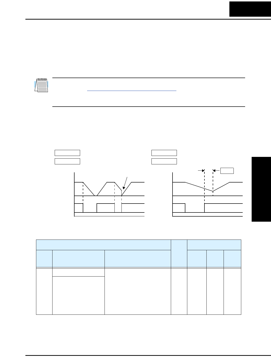
L2002 Inverter
Configuring
Drive Parameters
3–43
In most applications a controlled deceleration is desirable, corresponding to B091=00.
However, applications such as HVAC fan control will often use a free-run stop
(B091=01). This practice decreases dynamic stress on system components, prolonging
system life. In this case, you will typically set B088=01 in order to resume from the
current speed after a free-run stop (see diagram below, right). Note that using the default
setting, B088=00, can cause trip events when the inverter attempts to force the load
quickly to zero speed.
NOTE: Other events can cause (or be configured to cause) a free-run stop, such as
power loss (see “Automatic Restart Mode” on page 3–33), or an intelligent input
terminal [FRS] signal. If all free-run stop behavior is important to your application (such
as HVAC), be sure to configure each event accordingly.
An additional parameter further configures all instances of a free-run stop. Parameter
B003, Retry Wait Time Before Motor Restart, sets the minimum time the inverter will
free-run. For example, if B003 = 4 seconds (and B091=01) and the cause of the free-run-
stop lasts 10 seconds, the inverter will free-run (coast) for a total of 14 seconds before
driving the motor again.
Stop Mode = free-run stop
B091 =01 B091 =01
B088 =00 B088 =01
[FW, RV]
Motor
speed
t
Resume from 0Hz
Zero-frequency start
t
Stop Mode = free-run stop
Resume from current speed
[FW, RV]
Motor
speed
Wait time
B003
“B” Function Run
Mode
Edit
Lo Hi
Defaults
Func.
Code
Name /
SRW Display Description –FE(F)
(EU)
–FU
(USA) Units
B088 Restart mode after FRS Selects how the inverter
resumes operation when the
free-run stop (FRS) is
cancelled, two options:
00 .. Restart from 0Hz
01 .. Restart from frequency
detected from real speed of
motor (frequency matching)
✘ ✔ 00 00 —
RUN FRS ZST

“B” Group: Fine Tuning Functions
Configuring
Drive Parameters
3–44
B089: Monitor display select for networked inverter – When the L2002 inverter is
controlled via network, the inverter’s keypad display can still provide Monitor Mode.
The D00x parameter selected by function B089 will be displayed on the keypad. See
“Local Monitoring During Network Operation” on page 3–8 for more details.
B130/B131: Over-voltage LADSTOP Enable / Over-voltage LADSTOP Level – The over-
voltage LADSTOP function monitors the DC bus voltage and actively changes the
output frequency profile to maintain the DC bus voltage within settable limits. Although
“LAD” refers to “linear acceleration / deceleration,” the inverter only “STOPs” the
deceleration slope so that regenerative voltage will not cause the DC bus to rise enough
to cause an over-voltage trip event. Note that acceleration is not affected.
B089 Monitor display select
for networked inverter
Selects the parameter
displayed on the keypad
display when the inverter is
networked, 7 options:
01... Output frequency monitor
02... Output current monitor
03... Rotation direction
monitor
04... Process variable (PV),
PID feedback monitor
05... Intelligent input terminal
status
06... Intelligent output terminal
status
07... Scaled output frequency
monitor
✔ ✔ 01 01 —
PANEL d001
B091 Stop mode selection Selects how the inverter stops
the motor, two option codes:
00... DEC (decelerate and stop)
01... FRS (free run to stop)
✘ ✘ 00 00 —
STP Slct DEC
“B” Function Run
Mode
Edit
Lo Hi
Defaults
Func.
Code
Name /
SRW Display Description –FE(F)
(EU)
–FU
(USA) Units
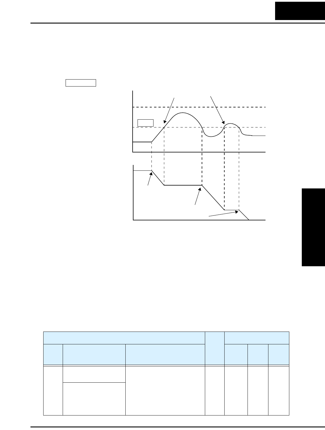
L2002 Inverter
Configuring
Drive Parameters
3–45
The graph below shows an inverter output profile that starts decelerating to a stop. At
two different points during the deceleration, regenerative voltage elevates the DC bus
level, exceeding the LADSTOP threshold set by B131. When the Over-voltage
LADSTOP feature is enabled by B130 = 01, the inverter stops the deceleration ramp in
each case until the DC bus level is again less than the threshold value.
When using the Over-voltage LADSTOP feature, please note the following:
• When the over-voltage LADSTOP feature is enabled (B130 = 01), the actual
deceleration is sometimes longer than the value set by parameters F003/F203.
• The over-voltage LADSTOP feature does not operate by maintaining a constant
DC bus voltage. So, it is still possible to have an over-voltage trip event during
extreme deceleration.
• If B131 is set lower than the normal DC bus voltage (when not in decel) by mistake, or
if the inverter’s input voltage increases enough, then the inverter will apply LADSTOP
(if enabled) all the time. In this case, the inverter can accelerate and run the motor, but
it cannot decelerate. If you are not sure that B131 > DC bus voltage, measure the DC
bus voltage in your installation and verify that the B131 value is higher.
OVLADSTOP = enable
B130 = 01
Output
frequency
t
t
Over-voltage protection
trip threshold
DC bus level
B131
Over-voltage
LADSTOP threshold
VInverter stops
deceleration
Deceleration
resumed
Start
deceleration
“B” Function Run
Mode
Edit
Lo Hi
Defaults
Func.
Code
Name /
SRW Display Description –FE(F)
(EU)
–FU
(USA) Units
B130 Over-voltage
LADSTOP enable
Pauses deceleration ramp when
DC bus voltage rises above
threshold level, in order to
avoid over-voltage trip.
Two option codes:
00 .. Disable
01 .. Enable
✘ ✔ 00 00 —
OVLADSTOP OFF

“B” Group: Fine Tuning Functions
Configuring
Drive Parameters
3–46
B150: Carrier Mode – If B083 Carrier Frequency setting is greater than 4 kHz, then
the B150 Carrier Mode function (if enabled) will reduce the actual carrier frequency
downward to 4 kHz as the inverter’s internal termperature increases.
B151: Quick start enable – This function and the intelligent input [RDY] (option code
52) have the same effect. If you need the inverter output to always have a quick response,
use parameter B151 and do not assign the [RDY] input. Otherwise, disable Quick Start
Enable (set B151=00) and assign the [RDY] input. Then you can enable the Quick Start
feature only when necessary. When the Quick Start feature is enabled, then access to
parameter editing is the same as when the inverter is in Run Mode.
NOTE: Parameter B151 cannot be read and copied to another inverter. This prevents
turning ON another inverter’s output unexpectedly.
B131 Over-voltage
LADSTOP level
Sets the threshold level for
over-voltage LADSTOP. When
the DC bus voltage is above the
threshold value, the inverter
stops deceleration until the DC
bus voltage is less than the
threshold setting again.
Two voltage ranges with 1V
resolution:
200V class: 330 to 390V
400V class: 660 to 780V
✔ ✔ 380 /
760
380 /
760
V
LADST LVL 00380V
“B” Function Run
Mode
Edit
Lo Hi
Defaults
Func.
Code
Name /
SRW Display Description –FE(F)
(EU)
–FU
(USA) Units
“B” Function Run
Mode
Edit
Lo Hi
Defaults
Func.
Code
Name /
SRW Display Description –FE(F)
(EU)
–FU
(USA) Units
B150 Carrier mode Automatically reduces the
actual carrier frequency as
needed to avoid internal
overheating. Two option codes:
00... Disable
01... Enable
✘ ✔ 00 00 —
Cr-DEC OFF
B151 Quick start enable Enables inverter output for
constant ON operation to speed
up response. Two option codes:
00... Disable
01... Enable
✔ ✔ 00 00 —
RDY-Func OFF
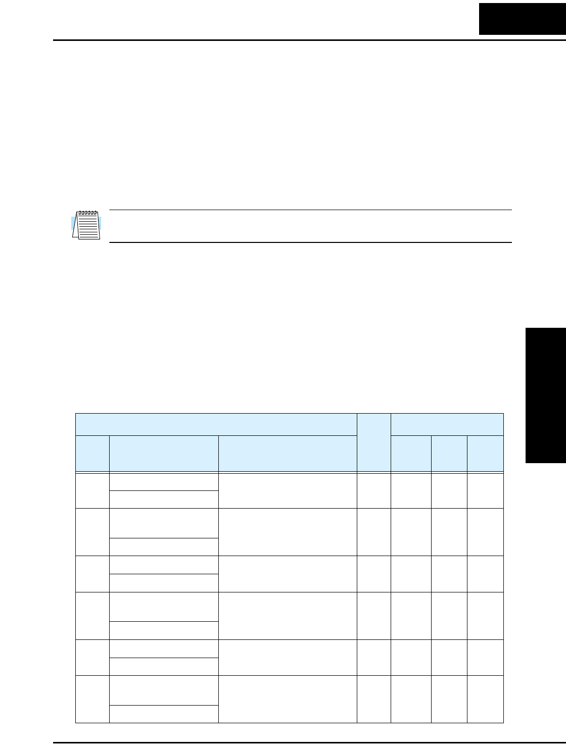
L2002 Inverter
Configuring
Drive Parameters
3–47
“C” Group: Intelligent Terminal Functions
The five input terminals [1], [2], [3], [4], and [5] can be configured for any of 19
different functions. The next two tables show how to configure the five terminals. The
inputs are logical, in that they are either OFF or ON. We define these states as OFF=0,
and ON=1.
The inverter comes with default options for the five terminals. These default settings are
initially unique, each one having its own setting. Note that European and US versions
have different default settings. You can use any option on any terminal, and even use the
same option twice to create a logical OR (though usually not required).
NOTE: Terminal [5] has the ability to be a logical input, and to be an analog input for a
thermistor device when the PTC function (option code 19) is assigned to that terminal.
Input Terminal Configuration
Functions and Options –The function codes in the following table let you assign one of
nineteen options to any of the five logic inputs for the L2002 inverters. The functions
C001through C005 configure the terminals [1] through [5] respectively. The “value” of
these particular parameters is not a scalar value, but it is a discrete number that selects
one option from many available options.
For example, if you set function C001=00, you have assigned option 00 (Forward Run)
to terminal [1]. The option codes and the specifics of how each one works are in
Chapter 4.
“C” Function Run
Mode
Edit
Lo Hi
Defaults
Func.
Code
Name /
SRW Display Description –FE(F)
(EU)
–FU
(USA) Units
C001 Terminal [1] function Select terminal [1] function,
29 options (see next section)
✘ ✘ 00
[FW]
00
[FW]
—
IN-TM 1 FW
C201 Terminal [1] function,
2nd motor
Select terminal [1] function,
29 options (see next section)
✘ ✘ 00
[FW]
00
[FW]
—
2IN-TM 1 FW
C002 Terminal [2] function Select terminal [2] function,
29 options (see next section)
✘ ✘ 01
[RV]
01
[RV]
—
IN-TM 2 RV
C202 Terminal [2] function,
2nd motor
Select terminal [2] function,
29 options (see next section)
✘ ✘ 01
[RV]
01
[RV]
—
2IN-TM 2 RV
C003 Terminal [3] function Select terminal [3] function,
29 options (see next section)
✘ ✘ 02
[CF1]
16
[AT]
—
IN-TM 3 AT
C203 Terminal [3] function,
2nd motor
Select terminal [3] function,
29 options (see next section)
✘ ✘ 02
[CF1]
16
[AT]
—
2IN-TM 3 AT

“C” Group: Intelligent Terminal Functions
Configuring
Drive Parameters
3–48
The input logic convention is programmable for each of the five inputs. Most inputs
default to normally open (active high), but you can select normally closed (active low) in
order to invert the sense of the logic.
C004 Terminal [4] function Select terminal [4] function,
29 options (see next section)
✘ ✘ 03
[CF2]
13
[USP]
—
IN-TM 4 USP
C204 Terminal [4] function,
2nd motor
Select terminal [4] function,
29 options (see next section)
✘ ✘ 03
[CF2]
13
[USP]
—
2IN-TM 4 USP
C005 Terminal [5] function Select terminal [5] function,
30 options (see next section)
✘ ✘ 18
[RS]
09
[2CH]
—
IN-TM 5 2CH
C205 Terminal [5] function,
2nd motor
Select terminal [5] function,
30 options (see next section)
✘ ✘ 18
[RS]
09
[2CH]
—
2IN-TM 5 2CH
“C” Function Run
Mode
Edit
Lo Hi
Defaults
Func.
Code
Name /
SRW Display Description –FE(F)
(EU)
–FU
(USA) Units
“C” Function Run
Mode
Edit
Lo Hi
Defaults
Func.
Code
Name /
SRW Display Description –FE(F)
(EU)
–FU
(USA) Units
C011 Terminal [1] active state Select logic convention, two
option codes:
00... normally open [NO]
01... normally closed [NC]
✘ ✘ 00 00 —
O/C-1 NO
C012 Terminal [2] active state Select logic convention, two
option codes:
00... normally open [NO]
01... normally closed [NC]
✘ ✘ 00 00 —
O/C-2 NO
C013 Terminal [3] active state Select logic convention, two
option codes:
00... normally open [NO]
01... normally closed [NC]
✘ ✘ 00 00 —
O/C-3 NO
C014 Terminal [4] active state Select logic convention, two
option codes:
00... normally open [NO]
01... normally closed [NC]
✘ ✘ 00 01 —
O/C-4 NC
C015 Terminal [5] active state Select logic convention, two
option codes:
00... normally open [NO]
01... normally closed [NC]
✘ ✘ 00 00 —
O/C-5 NO

L2002 Inverter
Configuring
Drive Parameters
3–49
NOTE: An input terminal configured for option code 18 ([RS] Reset command) cannot
be configured for normally closed operation.
Intelligent Input Terminal Overview
Each of the five intelligent terminals may be assigned any of the options in the following
table. When you program one of the option codes for terminal assignments C001 to
C005, the respective terminal assumes the function role of that option code. The terminal
functions have a symbol or abbreviation that we use to label a terminal using that
function. For example the “Forward Run” command is [FW]. The physical label on the
terminal block connector is simply 1, 2, 3, 4, or 5. However, schematic examples in this
manual also use the terminal symbol (such as [FW]) to show the assigned option. The
option codes for C011 to C015 determines the active state of the logical input (active
high or active low).
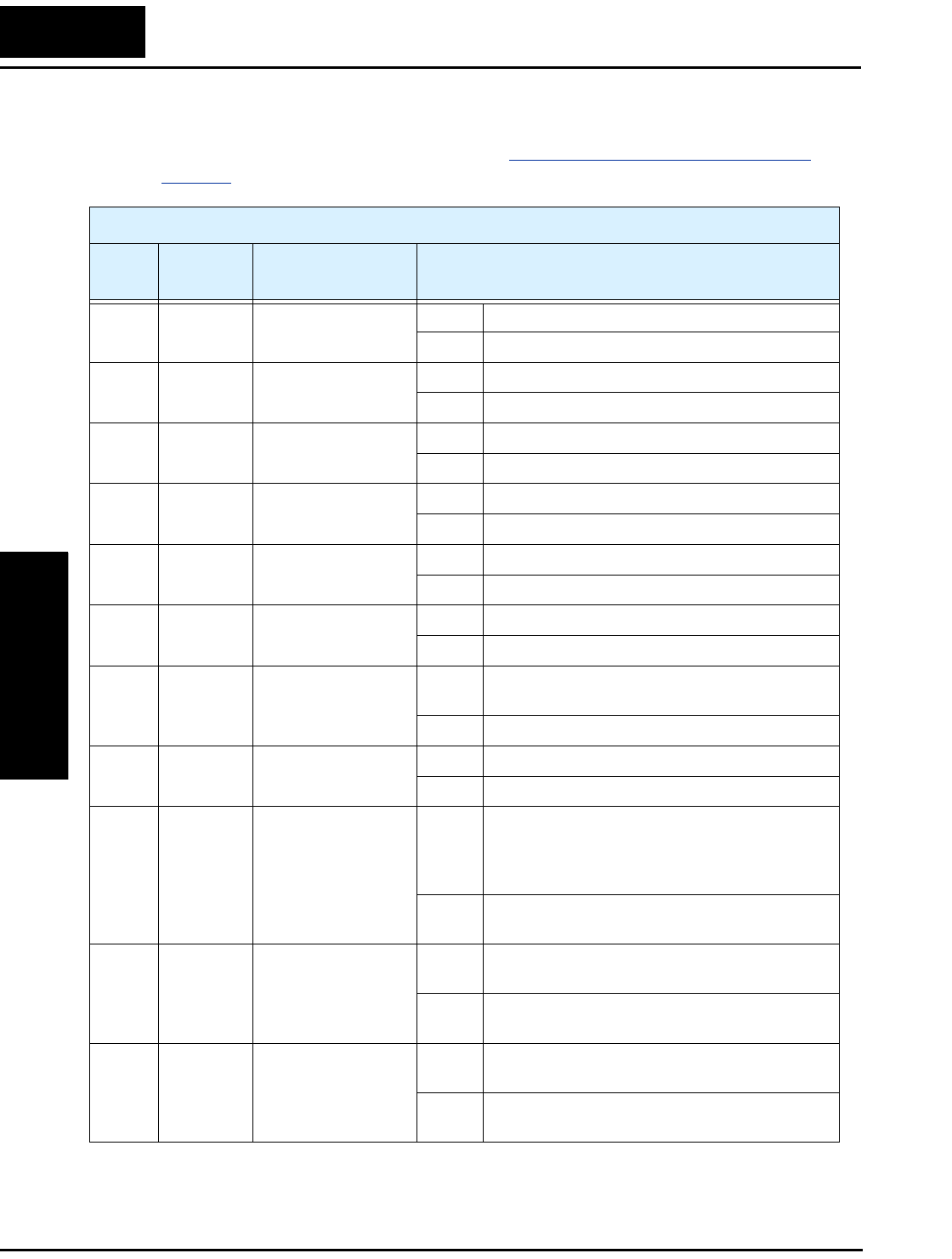
“C” Group: Intelligent Terminal Functions
Configuring
Drive Parameters
3–50
Input Function Summary Table – This table shows all twenty-four intelligent input
functions at a glance. Detailed descriptions of these functions, related parameters and
settings, and example wiring diagrams are in “Using Intelligent Input Terminals” on
page 4–9.
Input Function Summary Table
Option
Code
Terminal
Symbol Function Name Description
00 FW Forward Run/Stop ON Inverter is in Run Mode, motor runs forward
OFF Inverter is in Stop Mode, motor stops
01 RV Reverse Run/Stop ON Inverter is in Run Mode, motor runs reverse
OFF Inverter is in Stop Mode, motor stops
02 CF1 *1 Multi-speed Select,
Bit 0 (LSB)
ON Binary encoded speed select, Bit 0, logical 1
OFF Binary encoded speed select, Bit 0, logical 0
03 CF2 Multi-speed Select,
Bit 1
ON Binary encoded speed select, Bit 1, logical 1
OFF Binary encoded speed select, Bit 1, logical 0
04 CF3 Multi-speed Select,
Bit 2
ON Binary encoded speed select, Bit 2, logical 1
OFF Binary encoded speed select, Bit 2, logical 0
05 CF4 Multi-speed Select,
Bit 3 (MSB)
ON Binary encoded speed select, Bit 3, logical 1
OFF Binary encoded speed select, Bit 3, logical 0
06 JG Jogging ON Inverter is in Run Mode, output to motor runs at
jog parameter frequency
OFF Inverter is in Stop Mode
07 DB External DC Braking ON DC braking will be applied during deceleration
OFF DC braking will not be applied
08 SET Set (select) 2nd
Motor Data
ON The inverter uses 2nd motor parameters for
generating frequency output to motor. The selec-
tion of 1st or 2nd motor is available only during
Stop Mode.
OFF The inverter uses 1st (main) motor parameters
for generating frequency output to motor
09 2CH 2-stage Acceleration
and Deceleration
ON Frequency output uses 2nd-stage acceleration
and deceleration values
OFF Frequency output uses standard acceleration and
deceleration values
11 FRS Free-run Stop ON Causes output to turn OFF, allowing motor to
free run (coast) to stop
OFF Output operates normally, so controlled deceler-
ation stops motor

L2002 Inverter
Configuring
Drive Parameters
3–51
12 EXT External Trip ON When assigned input transitions OFF to ON,
inverter latches trip event and displays E12
OFF No trip event for ON to OFF, any recorded trip
events remain in history until Reset
13 USP Unattended Start
Protection
ON On powerup, the inverter will not resume a Run
command (mostly used in the US)
OFF On powerup, the inverter will resume a Run
command that was active before power loss
15 SFT Software Lock ON The keypad and remote programming devices
are prevented from changing parameters
OFF The parameters may be edited and stored
16 AT Analog Input
Voltage/current
Select
ON Terminal [OI] is enabled for current input (uses
terminal [L] for power supply return)
OFF Terminal [O] is enabled for voltage input (uses
terminal [L] for power supply return)
18 RS Reset Inverter ON The trip condition is reset, the motor output is
turned OFF, and powerup reset is asserted
OFF Normal power-ON operation
19 PTC PTC Thermistor
Thermal Protection
ANLG When a thermistor is connected to terminals [5]
and [L], the inverter checks for over-
temperature and will cause trip event and turn
OFF output to motor
OPEN A disconnect of the thermistor causes a trip
event, and the inverter turns OFF the motor
20 STA Start
(3-wire interface)
ON Starts the motor rotation
OFF No change to present motor status
21 STP Stop
(3-wire interface)
ON Stops the motor rotation
OFF No change to present motor status
22 F/R FWD, REV
(3-wire interface)
ON Selects the direction of motor rotation: ON =
FWD. While the motor is rotating, a change of
F/R will start a deceleration, followed by a
change in direction.
OFF Selects the direction of motor rotation: OFF =
REV. While the motor is rotating, a change of F/
R will start a deceleration, followed by a change
in direction.
Input Function Summary Table
Option
Code
Terminal
Symbol Function Name Description

“C” Group: Intelligent Terminal Functions
Configuring
Drive Parameters
3–52
23 PID PID Disable ON Temporarily disables PID loop control. Inverter
output turns OFF as long as PID Enable is active
(A071=01).
OFF Has no effect on PID loop operation, which
operates normally if PID Enable is active
(A071=01).
24 PIDC PID Reset ON Resets the PID loop controller. The main conse-
quence is that the integrator sum is forced to
zero.
OFF No effect on PID loop controller
27 UP Remote Control
UP Function (motor-
ized speed pot.)
ON Accelerates (increases output frequency) motor
from current frequency
OFF Output to motor operates normally
28 DWN Remote Control
DOWN Function
(motorized speed
pot.)
ON Decelerates (decreases output frequency) motor
from current frequency
OFF Output to motor operates normally
29 UDC Remote Control Data
Clearing
ON Clears the UP/DWN frequency memory by
forcing it to equal the set frequency parameter
F001. Setting C101 must be set=00 to enable this
function to work.
OFF UP/DWN frequency memory is not changed
31 OPE Operator Control ON Forces the source of the output frequency setting
(A001) and the source of the RUN command
(A002) to be from the digital operator
OFF Source of output frequency set by (A001) and
source of run command set by (A002) is used
50 ADD ADD frequency
enable
ON Adds the A145 value (Add Frequency) to the
output frequency
OFF Does not add the A145 value to the output
frequency
51 F-TM Force Terminal
Mode
ON Force inverter to use input terminals for output
frequency and Run command sources
OFF Source of output frequency set by (A001) and
source of Run command set by (A002) is used
52 RDY Quick Start Enable ON Inverter output is always ON (even when motor
rotation has stopped) to improve motor startup
time.
OFF Inverter output turns OFF normally in Stop
Mode.
Input Function Summary Table
Option
Code
Terminal
Symbol Function Name Description

L2002 Inverter
Configuring
Drive Parameters
3–53
Note 1: When using the Multi-speed Select settings CF1 to CF4, do not display
parameter F001 or change the value of F001 while the inverter is in Run Mode
(motor running). If it is necessary to check the value of F001 during Run
Mode, please monitor D001 instead of F001.
53 S-ST Special-Set (select)
2nd Motor Data
ON The inverter uses 2nd motor parameters for
generating frequency output to motor. The selec-
tion of 1st or 2nd motor is available during Stop
Mode or Run Mode.
OFF The inverter uses 1st (main) motor parameters
for generating frequency output to motor
255 —Not selected ON (input ignored)
OFF (input ignored)
Input Function Summary Table
Option
Code
Terminal
Symbol Function Name Description
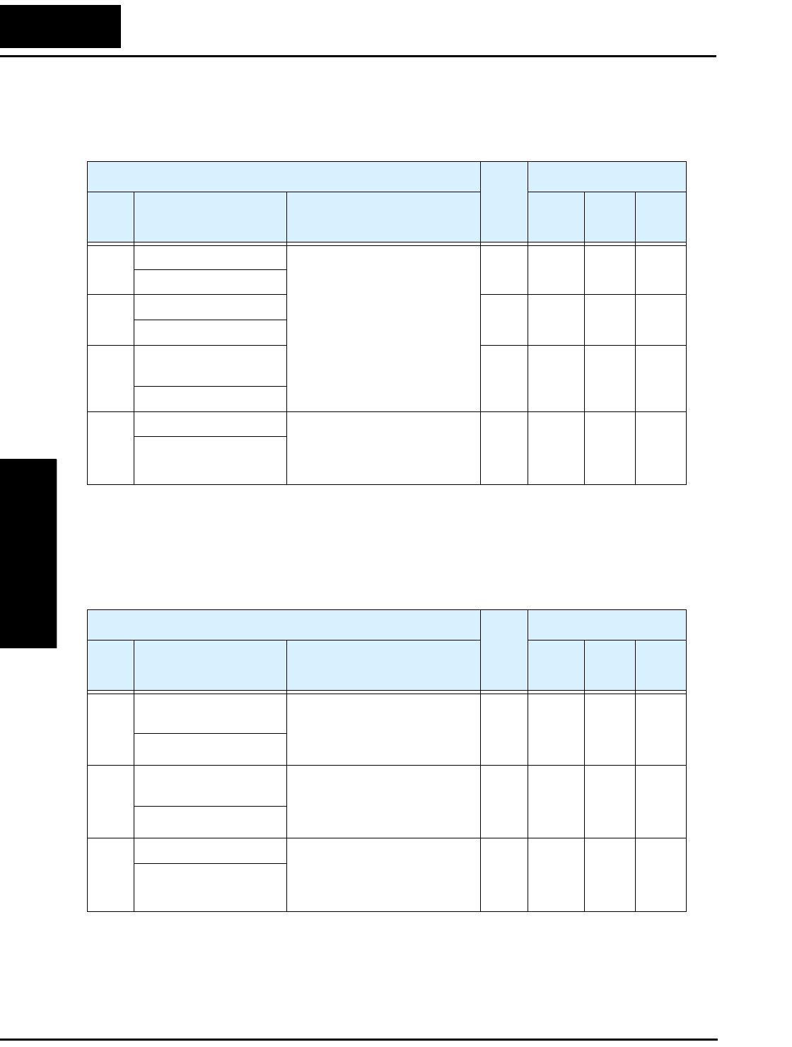
“C” Group: Intelligent Terminal Functions
Configuring
Drive Parameters
3–54
Output Terminal Configuration
The inverter provides configuration for logic (discrete) and analog outputs, shown in the
table below.
The output logic convention is programmable for terminals [11], [12], and the alarm
relay terminals. The open-collector output terminals [11] and [12] default to normally
open (active low), but you can select normally closed (active high) for these terminals in
order to invert the sense of the logic. You can invert the logical sense of the alarm relay
output as well.
“C” Function Run
Mode
Edit
Lo Hi
Defaults
Func.
Code
Name /
SRW Display Description –FE(F)
(EU)
–FU
(USA) Units
C021 Terminal [11] function
11 programmable functions
available for logic (discrete)
outputs (see next section)
✘ ✘ 01
[FA1]
01
[FA1]
—
OUT-TM 11 FA1
C022 Terminal [12] function ✘ ✘ 00
[RUN]
00
[RUN]
—
OUT-TM 12 RUN
C026 Alarm relay terminal
function
✘ ✘ 05
[AL]
05
[AL]
—
OUT-TM RY AL
C028 [AM] signal selection Two available functions:
00... Actual motor speed
01... Motor current
(see after next section)
✘ ✔ 00
output
freq.
00
output
freq.
—
AM-KIND F
“C” Function Run
Mode
Edit
Lo Hi
Defaults
Func.
Code
Name /
SRW Display Description –FE(F)
(EU)
–FU
(USA) Units
C031 Terminal [11] active
state
Select logic convention, two
option codes:
00... normally open (NO)
01... normally closed (NC)
✘ ✘ 00 00 —
O/C-11 NO
C032 Terminal [12] active
state
Select logic convention, two
option codes:
00... normally open (NO)
01... normally closed (NC)
✘ ✘ 00 00 —
O/C-12 NO
C036 Alarm relay active state Select logic convention, two
option codes:
00... normally open (NO)
01... normally closed (NC)
✘ ✘ 01 01 —
O/C-RY NC

L2002 Inverter
Configuring
Drive Parameters
3–55
Output Function Summary Table – This table shows all eleven functions for the
logical outputs (terminals [11], [12]) at a glance. Detailed descriptions of these
functions, related parameters and settings, and example wiring diagrams are in “Using
Intelligent Output Terminals” on page 4–35.
Output Function Summary Table
Option
Code
Terminal
Symbol Function Name Description
00 RUN Run Signal ON when inverter is in Run Mode
OFF when inverter is in Stop Mode
01 FA1 Frequency Arrival
Type 1 – Constant
Speed
ON when output to motor is at the set frequency
OFF when output to motor is OFF, or in any accelera-
tion or deceleration ramp
02 FA2 Frequency Arrival
Type 2 – Over-
frequency
ON when output to motor is at or above the FA2
threshold (C042) during accel
OFF when output to motor is below the FA2 threshold
(C043) during decel
03 OL Overload Advance
Notice Signal
ON when output current is more than the set thresh-
old for the overload signal
OFF when output current is less than the set threshold
for the overload signal
04 OD Output Deviation for
PID Control
ON when PID error is more than the set threshold for
the deviation signal
OFF when PID error is less than the set threshold for
the deviation signal
05 AL Alarm Signal ON when an alarm signal has occurred and has not
been cleared
OFF when no alarm has occurred since the last
clearing of alarm(s)
06 Dc Analog Input
Disconnect Detect
ON when the [O] input value < B082 setting (signal
loss detected), or the [OI] input current < 4mA
OFF when no signal loss is detected
07 FBV PID Second Stage
Output
ON Transitions to ON when the inverter is in RUN
Mode and the PID Process Variable (PV) is less
than the Feedback Low Limit (C053)
OFF Transitions to OFF the PID Feedback Value (PV)
exceeds the PID High Limit (C052), and transi-
tions to OFF when the inverter goes from Run
Mode to Stop Mode.
08 NDc ModBus Network
Detection Signal
ON when the communications watchdog timer
(period specified by C077) has timed out
OFF when the communications watchdog timer is
satisfied by regular communications activity
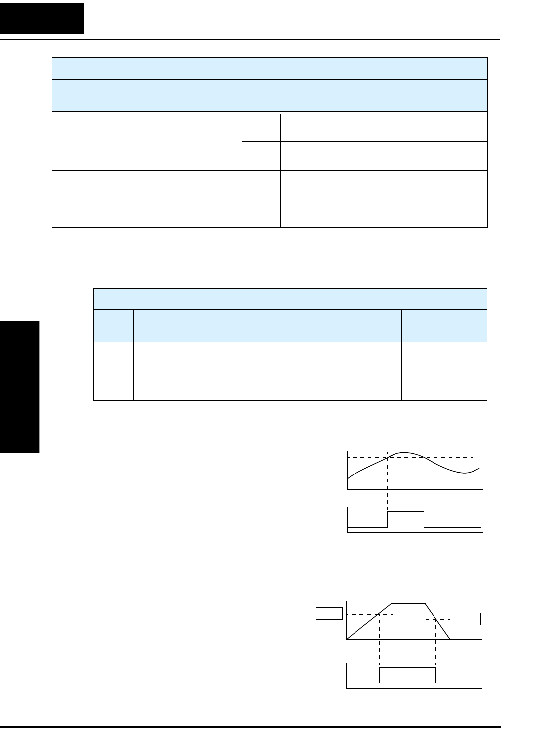
“C” Group: Intelligent Terminal Functions
Configuring
Drive Parameters
3–56
Analog Function Summary Table – This table shows both functions for the analog
voltage output [AM] terminal, configured by C028. More information on using and
calibrating the [AM] output terminal is in “Analog Output Operation” on page 4–55.
Output Function Adjustment Parameters
The following parameters work in
conjunction with the intelligent output
function, when configured. The overload
level parameter (C041) sets the motor
current level at which the overload signal
[OL] turns ON. The range of settings is
from 0% to 200% of the rated current for
the inverter. This function is for generating
an early warning logic output, without
causing either a trip event or a restriction
of the motor current (those effects are available on other functions).
The frequency arrival signal, [FA1] or
[FA2], is intended to indicate when the
inverter output has reached (arrived at) the
target frequency. You can adjust the timing
of the leading and trailing edges of the
signal via two parameters specific to accel-
eration and deceleration ramps, C042 and
C043.
09 LOG Logic Output
Function
ON when the Boolean operation specified by C143
has a logical “1” result
OFF when the Boolean operation specified by C143
has a logical “0” result
10 ODc Option Card
Detection Signal
ON when the communications watchdog timer
(period specified by P044) has timed out
OFF when the communications watchdog timer is
satisfied by regular communications activity
Output Function Summary Table
Option
Code
Terminal
Symbol Function Name Description
Analog Function Summary Table
Option
Code Function Name Description Range
00 Analog Frequency
Monitor
Actual motor speed 0 to max.
frequency in Hz
01 Analog Current Output
Monitor
Motor current (% of maximum rated
output current)
0 to 200%
Motor current
Overload
signal
t
t
0
1
0
C041
Output
frequency
Arrival
signal
t
t
0
1
0
C042 C043
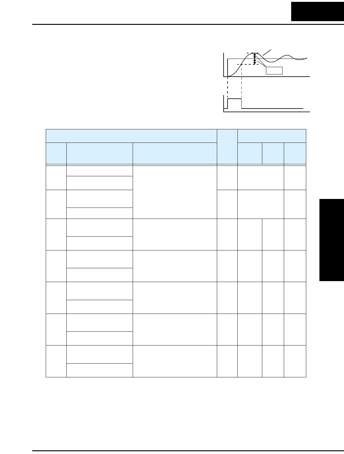
L2002 Inverter
Configuring
Drive Parameters
3–57
The Error for the PID loop is the magni-
tude (absolute value) of the difference
between the Setpoint (desired value) and
Process Variable (actual value). The PID
output deviation signal [OD] (output
terminal function option code 04)
indicates when the error magnitude has
exceeded a magnitude you define.
PID Error (PV–SP) deviation threshold
Deviation
signal
t
t
SP
Output PV
0
1
0
C044
“C” Function Run
Mode
Edit
Lo Hi
Defaults
Func.
Code
Name /
SRW Display Description –FE(F)
(EU)
–FU
(USA) Units
C041 Overload level setting Sets the overload signal level
between 0% and 200% (from 0
to two times the rated current
of the inverter)
✘ ✔ Rated current
for each inverter
model
A
OL LVL 001.60A
C241 Overload level setting,
2nd motor
✘ ✔ Rated current
for each inverter
model
A
2OLLVL 001.60A
C042 Frequency arrival
setting for acceleration
Sets the frequency arrival
setting threshold for the output
frequency during acceleration,
range is 0.0 to 400.0 Hz
✘ ✔ 0.0 0.0 Hz
ARV ACC 0000.0Hz
C043 Arrival frequency
setting for deceleration
Sets the frequency arrival
setting threshold for the output
frequency during deceleration,
range is 0.0 to 400.0 Hz
✘ ✔ 0.0 0.0 Hz
ARV DEC 0000.0Hz
C044 PID deviation level
setting
Sets the allowable PID loop
error magnitude (absolute
value), SP - PV, range is 0.0 to
100%, resolution is 0.1%
✘ ✔ 3.0 3.0 %
ARV PID 003.0%
C052 PID FBV function
high limit
When the PV exceeds this
value, the PID loop turns OFF
the PID Second Stage Output,
range is 0.0 to 100.0%
✘ ✔ 100.0 100.0 %
PID LtU 0100.0%
C053 PID FBV function
variable low limit
When the PV goes below this
value, the PID loop turns ON
the PID Second Stage Output,
range is 0.0 to 100.0%
✘ ✔ 0.0 0.0 %
PID LtL 0000.0%

“C” Group: Intelligent Terminal Functions
Configuring
Drive Parameters
3–58
Network Communication Settings
The following table lists parameters that configure the inverter’s serial communications
port. The settings affect how the inverter communicates with a digital operator (such as
SRW–0EX), as well as a ModBus network (for networked inverter applications). The
settings cannot be edited via the network, in order to ensure network reliability. Refer to
“ModBus Network Communications” on page B–1 for more information on controlling
and monitoring your inverter from a network.
“C” Function Run
Mode
Edit
Lo Hi
Defaults
Func.
Code
Name /
SRW Display Description –FE(F)
(EU)
–FU
(USA) Units
C071 Communication speed
selection
Three option codes:
04... 4800 bps
05... 9600 bps
06... 19200 bps
✘ ✔ 06 04 baud
COM BAU 4800
C072 Node allocation Set the address of the inverter
on the network. Range is 1 to
32.
✘ ✔ 1. .1 —
COM ADR 00001
C074 Communication parity
selection
Three option codes:
00... No parity
01... Even parity
02... Odd parity
✘ ✔ 00 00 —
COM PRTY NON
C075 Communication stop bit
selection
Range is 1 to 2 ✘ ✔ 11—
COM STP 1BIT
C076 Communication error
select
Selects inverter response to
communications error.
Five options:
00... Trip (error code E60)
01... Decelerate to a stop and
trip (error code E60)
02... Disable
03... Free run stop (coasting)
04... Decelerate to a stop
✘ ✔ 02 02 —
COM ESlct None
C077 Communication error
time-out
Sets the communications
watchdog timer period.
Range is 0.00 to 99.99 sec.
✘ ✔ 0.00 0.00 sec.
COM ETIM 000.00s
C078 Communication wait
time
Time the inverter waits after
receiving a message before it
transmits.
Range is 0. to 1000. ms
✘ ✔ 0. 0. msec.
COM Wait 00000ms

L2002 Inverter
Configuring
Drive Parameters
3–59
Analog Signal Calibration Settings
The functions in the following table configure the signals for the analog output termi-
nals. Note that these settings do not change the current/voltage or sink/source character-
istics—only the zero and span (scaling) of the signals.
NOTE: When you restore factory default settings, the values will change to those listed
above. Be sure to manually reconfigure the values for your application, if needed, after
restoring factory defaults.
“C” Function Run
Mode
Edit
Lo Hi
Defaults
Func.
Code
Name /
SRW Display Description –FE(F)
(EU)
–FU
(USA) Units
C081 O input span calibration Scale factor between the
external frequency command
on terminals L – O (voltage
input) and the frequency
output, range is 0.0 to 200.0%
✔ ✔ 100.0 100.0 %
O-ADJ 0100.0%
C082 OI input span calibra-
tion
Scale factor between the
external frequency command
on terminals L – OI (current
input) and the frequency
output, range is 0.0 to 200.0%
✔ ✔ 100.0 100.0 %
OI-ADJ 0100.0%
C085 Thermistor input tuning Range is 0.0 to 200.0% ✔ ✔ 100.0 100.0 %
PTC Adj 0100.0%
C086 [AM] terminal offset
tuning
Range is 0.0 to 10.0V ✔ ✔ 0.0 0.0 V
AM-OFFST 0000.0V

“C” Group: Intelligent Terminal Functions
Configuring
Drive Parameters
3–60
Miscellaneous Functions
The following table contains miscellaneous functions not in other function groups.
“C” Function Run
Mode
Edit
Lo Hi
Defaults
Func.
Code
Name /
SRW Display Description –FE(F)
(EU)
–FU
(USA) Units
C091 Debug mode enable Displays debug parameters.
Two option codes:
00... Disable
01... Enable
✔ ✔ 00 00 —
DBG Slct OFF
C101 Up/Down memory
mode selection
Controls speed setpoint for the
inverter after power cycle. Two
option codes:
00... Clear last frequency
(return to default frequency
F001)
01... Keep last frequency
adjusted by UP/DWN
✘ ✔ 00 00 —
UP/DWN NO-STR
C102 Reset selection Determines response to Reset
input [RST].
Three option codes:
00... Cancel trip state at input
signal ON transition, stops
inverter if in Run Mode
01... Cancel trip state at signal
OFF transition, stops inverter if
in Run Mode
02... Cancel trip state at input
signal ON transition, no effect
if in Run Mode
✘ ✔ 00 00 —
RS Slct ON
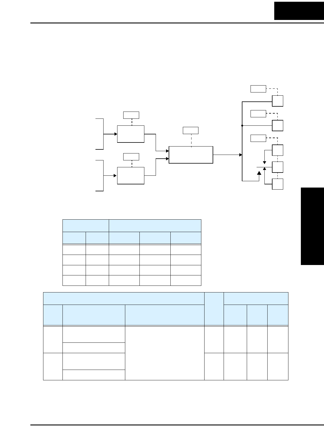
L2002 Inverter
Configuring
Drive Parameters
3–61
Output Logic and Timing
Logic Output Function – The inverter has a built-in logic output feature. You can select
any two of the other nine intelligent output options for internal inputs. Then, configure
the logic function to apply the logical AND, OR, or XOR (exclusive OR) operator as
desired to the two inputs. The terminal symbol for the new output is [LOG]. Use C021,
C022, or C026 to route the logical result to terminal [11], [12], or the relay terminals.
The following table shows all four possible logic input combinations with each of the
three available logical operations.
Input States [LOG] Output State
A B AND OR XOR
00000
01011
10011
11110
C141
Logic function
AND, OR, XOR
Input A
RUN, FA1,
FA2, OL,
OD, AL, Dc,
FBV, NDc
Intelligent out-
puts used as
internal inputs:
C142
Input B
RUN, FA1,
FA2, OL,
OD, AL, Dc,
FBV, NDc
C143
12
11
AL1
AL0
AL2
C021
C022
C026
[LOG]
“C” Function Run
Mode
Edit
Lo Hi
Defaults
Func.
Code
Name /
SRW Display Description –FE(F)
(EU)
–FU
(USA) Units
C141 Input A select for logic
output
9 programmable functions
available for logic (discrete)
outputs
✘ ✘ 00 00 —
LogicOut1 RUN
C142 Input B select for logic
output
✘ ✘ 01 01 —
LogicOut2 FA1
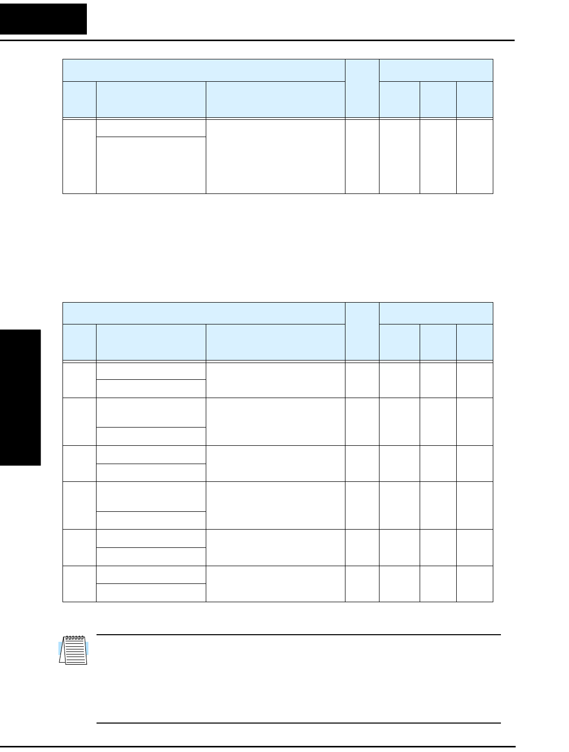
“C” Group: Intelligent Terminal Functions
Configuring
Drive Parameters
3–62
Output Signal ON/OFF Delay Function - Intelligent outputs including terminals [11],
[12], and the output relay, have configurable signal transition delays. Each output can
delay either the OFF-to-ON or ON-to-OFF transitions, or both. Signal transition delays
are variable from 0.1 to 100.0 seconds. This feature is useful in applications that must
tailor inverter output signals to meet timing requirements of certain external devices.
NOTE: If you are using the output terminal OFF delay feature (any of C145, C147,
C149 > 0.0 sec.), the [RS] (Reset) terminal affects the ON-to-OFF transition slightly.
Normally (without using OFF delays), the [RS] input causes the motor output and the
logic outputs to turn OFF together, immediately. However, when any output uses an OFF
delay, then after the [RS] input turns ON, that output will remain ON for an additional 1
sec. period (approximate) before turning OFF.
C143 Logic function select Applies a logic function to
calculate [LOG] output state,
three options:
00... [LOG] = A AND B
01... [LOG] = A OR B
02... [LOG] = A XOR B
✘ ✘ 00 00 —
LogicOPE AND
“C” Function Run
Mode
Edit
Lo Hi
Defaults
Func.
Code
Name /
SRW Display Description –FE(F)
(EU)
–FU
(USA) Units
“C” Function Run
Mode
Edit
Lo Hi
Defaults
Func.
Code
Name /
SRW Display Description –FE(F)
(EU)
–FU
(USA) Units
C144 Terminal [11] ON delay Range is 0.0 to 100.0 sec. ✘ ✔ 0.0 0.0 sec.
DLAY 11 0000.0s
C145 Terminal [11] OFF
delay
Range is 0.0 to 100.0 sec. ✘ ✔ 0.0 0.0 sec.
HOLD 11 0000.0s
C146 Terminal [12] ON delay Range is 0.0 to 100.0 sec. ✘ ✔ 0.0 0.0 sec.
DLAY 12 0000.0s
C147 Terminal [12] OFF
delay
Range is 0.0 to 100.0 sec. ✘ ✔ 0.0 0.0 sec.
HOLD 12 0000.0s
C148 Output relay ON delay Range is 0.0 to 100.0 sec. ✘ ✔ 0.0 0.0 sec.
DLAY RY 0000.0s
C149 Output relay OFF delay Range is 0.0 to 100.0 sec. ✘ ✔ 0.0 0.0 sec.
HOLD RY 0000.0s
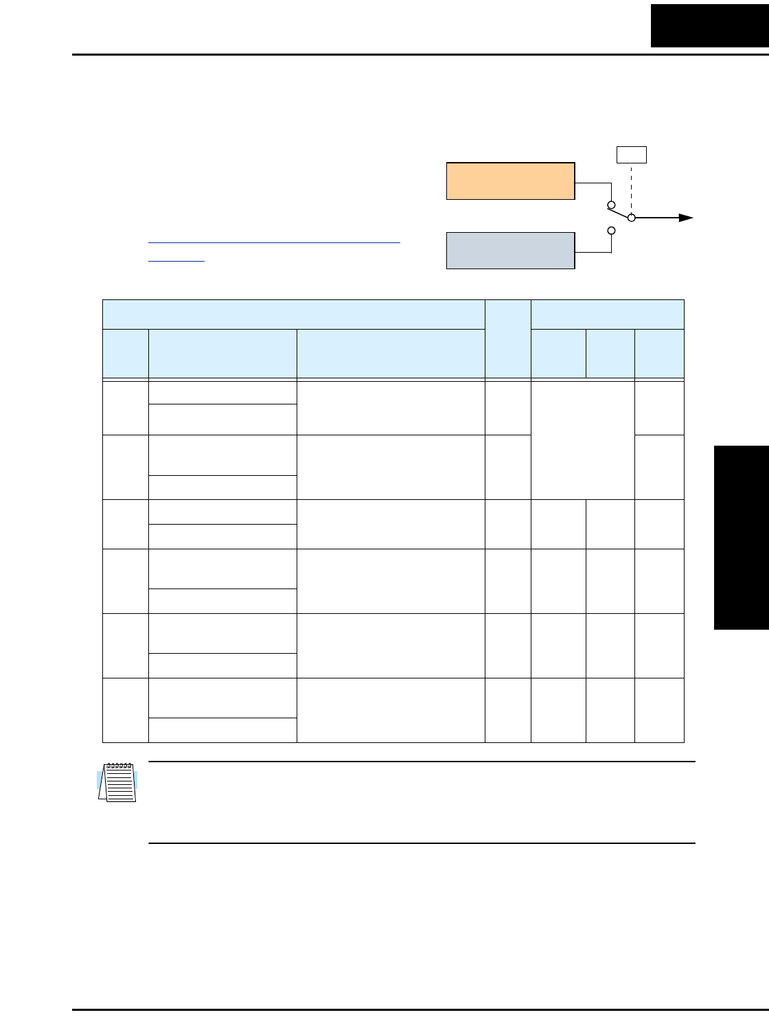
L2002 Inverter
Configuring
Drive Parameters
3–63
“H” Group: Motor Constants Functions
The “H” Group parameters configure the
inverter for the motor characteristics. You
must manually set H003 and H004 values to
match the motor. Parameter H006 is factory-
set. If you want to reset the parameters to the
factory default settings, use the procedure in
“Restoring Factory Default Settings” on
page 6–8. Use A044 to select the torque
control algorithm as shown in the diagram.
NOTE: If you are using automatic torque boost (A041/A241 = 01) and the output
current is unstable in the low frequency range, be sure to adjust A042/A242 and
A043/A243 with H006/H206 in order to decrease the boost voltage as an addition to the
standard V/f curve.
Output
A44
V/f control,
constant torque
V/f control,
variable torque
00
01
Inverter Torque Control Algorithms
“H” Function Run
Mode
Edit
Lo Hi
Defaults
Func.
Code
Name /
SRW Display Description –FE(F)
(EU)
–FU
(USA) Units
H003 Motor capacity Nine selections:
0.2 / 0.4 / 0.75 / 1.5 / 2.2 / 3.7
5.5 / 7.5 / 11
✘ ✘ Specified by the
capacity of each
inverter model
kW
AUX K 0.4 kW
H203 Motor capacity, 2nd
setting
Nine selections:
0.2 / 0.4 / 0.75 / 1.5 / 2.2 / 3.7
5.5 / 7.5 / 11
✘ ✘ kW
2AUXK 0.4 kW
H004 Motor poles setting Four selections:
2 / 4 / 6 / 8
✘ ✘ 4 4 poles
AUX P 4p
H204 Motor poles setting, 2nd
motor
Four selections:
2 / 4 / 6 / 8
✘ ✘ 4 4 poles
2AUXP 4p
H006 Motor stabilization
constant
Motor constant (factory set),
range is 0 to 255
✔ ✔ 100 100 —
AUX KCD 100
H206 Motor stabilization
constant, 2nd motor
Motor constant (factory set),
range is 0 to 255
✔ ✔ 100 100 —
2AUXKCD 100

“P” Group: Expansion Card Functions
Configuring
Drive Parameters
3–64
“P” Group: Expansion Card Functions
The (optional) expansion card for the L2002 inverter has assiciated configuration data.
The following table defines the functions and their value ranges. Please refer to the
expansion card manual for more details.
NOTE: The “P” Group parameters do not appear in the parameter list shown on the
keypad display unless the expansion card is installed on the inverter.
“P” Function Run
Mode
Edit
Lo Hi
Defaults
Func.
Code
Name /
SRW Display Description –FE(F)
(EU)
–FU
(USA) Units
P044 Network comm
watchdog timer
Range is 0.00 to 99.99 ✘ ✘ 1.00 1.00 sec.
TIMER 01.00s
P045 Inverter action on
network comm error
Five options:
00... Trip (Error Code E70)
01... Decelerate to stop and trip
(Error Code E70)
02... Hold last speed
03... Free run stop
04... Decelerate and stop
✘ ✘ 01 01 —
T-OUT FTP
P046 Polled I/O output
instance number
Three settings:
20, 21, 100
✘ ✘ 21 21 —
O-AS-INS 021
P047 Polled I/O input
instance number
Three settings:
70, 71, 101
✘ ✘ 71 71 —
O-AS-INS 071
P048 Inverter action on
network idle mode
Five options:
00... Trip (Error Code E70)
01... Decelerate to stop and trip
(Error Code E70)
02... Hold last speed
03... Free run stop
04... Decelerate and stop
✘ ✘ 01 01 —
IDLE FTP
P049 Network motor poles
setting for RPM
Range is 00 to 38 (even
numbers only)
✘ ✘ 00—
P 00P

Operations
and Monitoring
In This Chapter.... page
— Introduction ..................................................... 2
— Connecting to PLCs and Other Devices ......... 4
— Control Logic Signal Specifications................. 6
— Intelligent Terminal Listing............................... 7
— Using Intelligent Input Terminals ..................... 9
— Using Intelligent Output Terminals ................ 35
— Analog Input Operation ................................. 53
— Analog Output Operation .............................. 55
— PID Loop Operation ...................................... 56
— Configuring the Inverter for Multiple Motors .. 58
4

Introduction
Operations
and Monitoring
4–2
Introduction
The previous material in Chapter 3 gave a reference listing of all the programmable
functions of the inverter. We suggest that you first scan through the listing of inverter
functions to gain a general familiarity. This chapter will build on that knowledge in the
following ways:
1. Related functions – Some parameters interact with or depend on the settings in other
functions. This chapter lists “required settings” for a programmable function to serve
as a cross-reference and an aid in showing how functions interact.
2. Intelligent terminals – Some functions rely on an input signal on a control logic
connector terminal, or generate output signals in other cases.
3. Electrical interfaces – This chapter shows how to make connections between the
inverter and other electrical devices.
4. PID Loop Operation – The L2002 has a built-in PID loop that calculates the optimal
inverter output frequency to control an external process. This chapter shows the
parameters and input/output terminals associated with PID loop operation.
5. Multiple motors – A single L2002 inverter may be used with two or more motors in
some types of applications. This chapter shows the electrical connections and inverter
parameters involved in multiple-motor applications.
The topics in this chapter can help you decide the features that are important to your
application, and how to use them. The basic installation covered in Chapter 2 concluded
with the powerup test and running the motor. Now, this chapter starts from that point and
shows how to make the inverter part of a larger control or automation system.
Caution Messages for Operating Procedures
Before continuing, please read the following Caution messages.
CAUTION: The heat sink fins will have a high temperature. Be careful not to touch
them. Otherwise, there is the danger of getting burned.
CAUTION: The operation of the inverter can be easily changed from low speed to high
speed. Be sure check the capability and limitations of the motor and machine before
operating the inverter. Otherwise, it may cause injury to personnel.
CAUTION: If you operate a motor at a frequency higher than the inverter standard
default setting (50Hz/60Hz), be sure to check the motor and machine specifications with
the respective manufacturer. Only operate the motor at elevated frequencies after getting
their approval. Otherwise, there is the danger of equipment damage.

L2002 Inverter
Operations
and Monitoring
4–3
Warning Messages for Operating Procedures
Before continuing, please read the following Warning messages.
WARNING: Be sure to turn ON the input power supply only after closing the front case.
While the inverter is energized, be sure not to open the front case. Otherwise, there is the
danger of electric shock.
WARNING: Be sure not to operate electrical equipment with wet hands. Otherwise,
there is the danger of electric shock.
WARNING: While the inverter is energized, be sure not to touch the inverter terminals
even when the motor is stopped. Otherwise, there is the danger of electric shock.
WARNING: If the Retry Mode is selected, the motor may suddenly restart after a trip
stop. Be sure to stop the inverter before approaching the machine (be sure to design the
machine so that safety for personnel is secure even if it restarts.) Otherwise, it may cause
injury to personnel.
WARNING: If the power supply is cut OFF for a short period of time, the inverter may
restart operation after the power supply recovers if the Run command is active. If a
restart may pose danger to personnel, so be sure to use a lock-out circuit so that it will
not restart after power recovery. Otherwise, it may cause injury to personnel.
WARNING: The Stop Key is effective only when the Stop function is enabled. Be sure
to enable the Stop Key separately from the emergency stop. Otherwise, it may cause
injury to personnel.
WARNING: During a trip event, if the alarm reset is applied and the Run command is
present, the inverter will automatically restart. Be sure to apply the alarm reset only after
verifying the Run command is OFF. Otherwise, it may cause injury to personnel.
WARNING: Be sure not to touch the inside of the energized inverter or to put any
conductive object into it. Otherwise, there is a danger of electric shock and/or fire.
WARNING: If power is turned ON when the Run command is already active, the motor
will automatically start and injury may result. Before turning ON the power, confirm that
the RUN command is not present.
WARNING: When the Stop key function is disabled, pressing the Stop key does not
stop the inverter, nor will it reset a trip alarm.
WARNING: Be sure to provide a separate, hard-wired emergency stop switch when the
application warrants it.
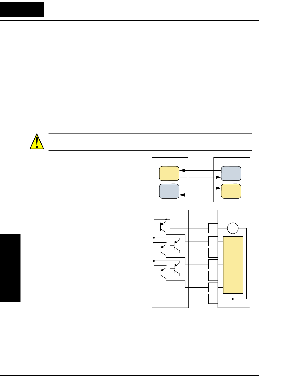
Connecting to PLCs and Other Devices
Operations
and Monitoring
4–4
Connecting to PLCs and Other Devices
Hitachi inverters (drives) are useful in many types of applications. During installation,
the inverter keypad (or other programming device) will facilitate the initial configura-
tion. After installation, the inverter will generally receive its control commands through
the control logic connector or serial interface from another controlling device. In a
simple application such as single-conveyor speed control, a Run/Stop switch and poten-
tiometer will give the operator all the required control. In a sophisticated application,
you may have a programmable logic controller (PLC) as the system controller, with
several connections to the inverter.
It is not possible to cover all the possible types of application in this manual. It will be
necessary for you to know the electrical characteristics of the devices you want to
connect to the inverter. Then, this section and the following sections on I/O terminal
functions can help you quickly and safely connect those devices to the inverter.
CAUTION: It is possible to damage the inverter or other devices if your application
exceeds the maximum current or voltage characteristics of a connection point.
The connections between the inverter and
other devices rely on the electrical input/
output characteristics at both ends of each
connection, shown in the diagram to the
right. The inverter’s configurable inputs
accept either a sourcing or sinking output
from an external device (such as a PLC).
This chapter shows the inverter’s internal
electrical component(s) at each I/O termi-
nal. In some cases, you will need to insert
a power source in the interface wiring.
In order to avoid equipment damage and
get your application running smoothly, we
recommend drawing a schematic of each
connection between the inverter and the
other device. Include the internal compo-
nents of each device in the schematic, so
that it makes a complete circuit loop.
After making the schematic, then:
1. Verify that the current and voltage for
each connection is within the operating
limits of each device.
2. Make sure that the logic sense (active high or active low) of any ON/OFF connection
is correct.
3. Check the zero and span (curve end points) for analog connections, and be sure the
scale factor from input to output is correct.
4. Understand what will happen at the system level if any particular device suddenly
loses power, or powers up after other devices.
Other device
Input
circuit
Output
circuit
Inverter
Input
circuit
Output
circuit
PCS
1
2
3
4
5
L
Input
circuits
+–
signal
signal
return
return
PLC Inverter
24V
GND
+Com
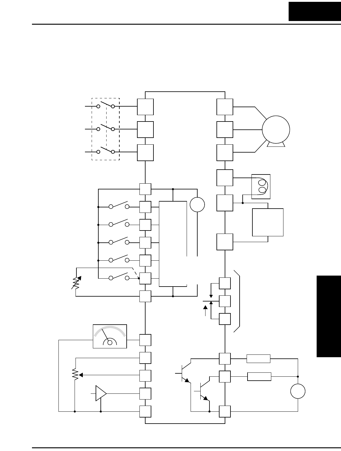
L2002 Inverter
Operations
and Monitoring
4–5
Example Wiring Diagram
The schematic diagram below provides a general example of logic connector wiring, in
addition to basic power and motor wiring covered in Chapter 2. The goal of this chapter
is to help you determine the proper connections for the various terminals shown below
for your specific application needs.
12
11
1
2
3
4
5
L
L
H
O
OI
AM
CM2
L2002
PCS
AL1
AL0
AL2
Relay contacts,
type 1 Form C
Open collector outputs
Analog reference
Power source,
3-phase or
1-phase, per
inverter model
R
(L1)
S
(L2)
T
N(L3)
U
(T1)
V
(T2)
W
(T3)
Motor
Forward
Reverse
Intelligent inputs,
5 terminals
4–20mA
0–10VDC
NOTE: For the wir-
ing of intelligent I/O
and analog inputs, be
sure to use twisted
pair / shielded cable.
Attach the shield wire
for each signal to its
respective common
terminal at the
inverter end only.
Thermistor
Meter
GND for analog signals
Load
Freq. arrival signal
Run signal
Load
+
–
GND for logic outputs
Input
circuits
[5] configurable as
discrete input or
thermistor input
GND for logic inputs
+
–
24V
PD/+1
PD/+
N/–
Braking
unit
(optional)
DC reactor
(optional)
Output
circuits
Breaker,
MCCB or GFI
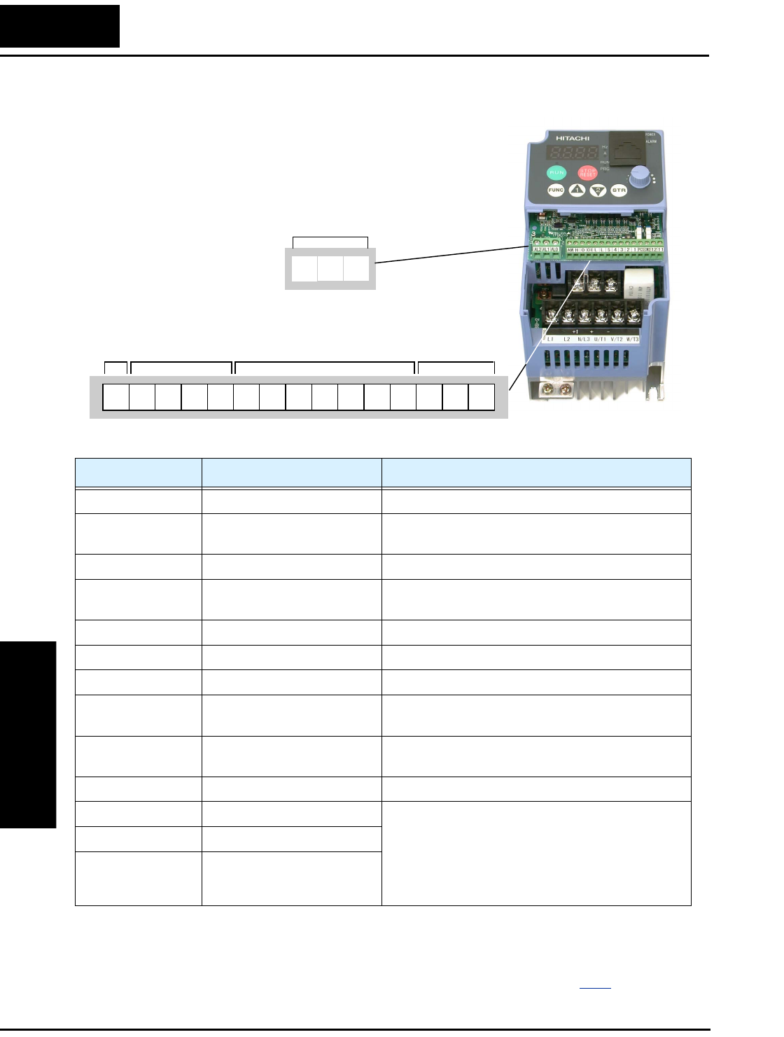
Control Logic Signal Specifications
Operations
and Monitoring
4–6
Control Logic Signal Specifications
Specifications for the logic connection terminals are in the following table:
Note 1: The two terminals [L] are electrically connected together inside the inverter.
Note 2: We recommend using [L] logic GND (to the right) for logic input circuits and
[L] analog GND (to the left) for analog I/O circuits.
Note 3: Default relay N.O./N.C. configuration is reversed. See page 4–36.
Relay contacts
Logic inputs
Analog
inputs
Analog
output
Logic
outputs
12 1112345LLH O
OIAM
CM2PCS
AL2 AL0AL1
The control logic connectors are located just
behind the front housing cover. The relay contacts
are just to the left of the logic connectors.
Connector labeling is shown below.
Terminal Name Description Ratings
[PCS] +24V for logic inputs 24VDC, 100 mA max. (do not short to terminal L)
[1], [2], [3], [4], [5] Discrete logic inputs 27VDC max. (use PCS or an external supply refer-
enced to terminal L)
[L] (right) *1 GND for logic inputs sum of input [1]—[5] currents (return)
[11], [12] Discrete logic outputs 50mA maximum ON state current,
27 VDC maximum OFF state voltage
[CM2] GND for logic outputs 100 mA: sum of 11 and 12 currents (return)
[AM] Analog voltage output 0 to 10VDC, 1mA maximum
[L] (left) *2 GND for analog signals sum of OI, O, H, and AM currents (return)
[OI] Analog input, current 4 to 19.6 mA range, 20 mA nominal,
input impedance 250 Ω
[O] Analog input, voltage 0 to 9.8 VDC range, 10VDC nominal,
input impedance 10 kΩ
[H] +10V analog reference 10VDC nominal, 10 mA max
[AL0] Relay common contact 250 VAC, 2.5A (R load) max.,
250 VAC, 0.2A (I load, P.F.=0.4) max.
100 VAC, 10mA min.
30 VDC, 3.0A (R load) max.
30 VDC, 0.7A (I load, P.F.=0.4) max.
5 VDC, 100mA min.
[AL1] *3 Relay contact, normally open
[AL2] *3 Relay contact, normally
closed
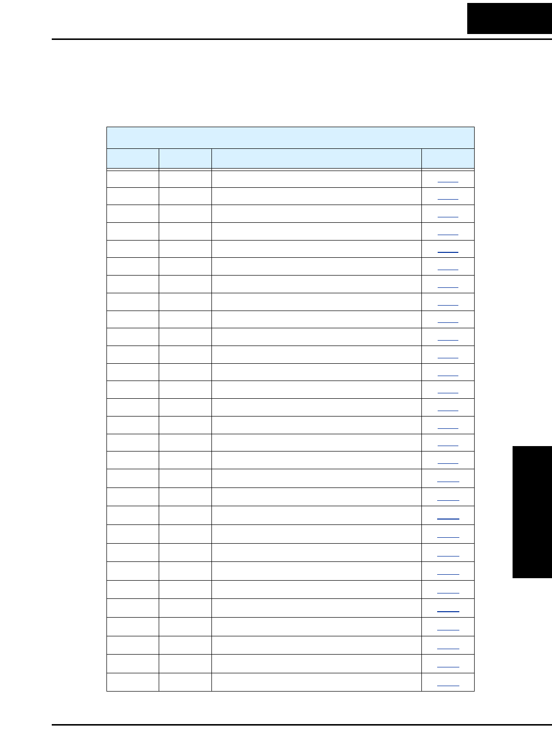
L2002 Inverter
Operations
and Monitoring
4–7
Intelligent Terminal Listing
Intelligent Inputs
Use the following table to locate pages for intelligent input material in this chapter.
Intelligent INPUTS
Symbol Code Name Page
FW 00 Forward Run/Stop 4–12
RV 01 Reverse Run/Stop 4–12
CF1 02 Multi-speed Select, Bit 0 (LSB) 4–13
CF2 03 Multi-speed Select, Bit 1 4–13
CF3 04 Multi-speed Select, Bit 2 4–13
CF4 05 Multi-speed Select, Bit 3 4–13
JG 06 Jogging 4–15
DB 07 External DC Braking 4–16
SET 08 Set Second Motor 4–17
2CH 09 2-stage Acceleration and Deceleration 4–18
FRS 11 Free-run Stop 4–19
EXT 12 External Trip 4–20
USP 13 Unattended Start Protection 4–21
SFT 15 Software Lock 4–22
AT 16 Analog Input Voltage/current Select 4–23
RS 18 Reset Inverter 4–24
PTC 19 Thermistor Thermal Protection 4–25
STA 20 Start (3-wire interface) 4–26
STP 21 Stop (3-wire interface) 4–26
F/R 22 FWD, REV (3-wire interface) 4–26
PID 23 PID Disable 4–28
PIDC 24 PID Reset 4–28
UP 27 Remote Control UP Function 4–29
DWN 28 Remote Control DOWN Function 4–29
UDC 29 Remote Control Data Clearing 4–29
OPE 31 Operator Control 4–31
ADD 50 ADD Frequency Enable 4–32
F-TM 51 Force Terminal Mode 4–33
RDY 52 Quick Start Enable 4–34
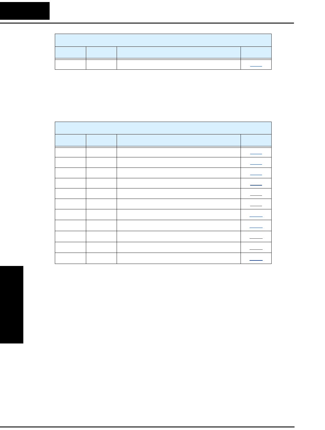
Intelligent Terminal Listing
Operations
and Monitoring
4–8
Intelligent Outputs
Use the following table to locate pages for intelligent output material in this chapter.
S-ST 53 Special-Set Second Motor 4–17
Intelligent INPUTS
Symbol Code Name Page
Intelligent OUTPUTS
Symbol Code Name Page
RUN 00 Run Signal 4–38
FA1 01 Frequency Arrival Type 1 – Constant Speed 4–39
FA2 02 Frequency Arrival Type 2 – Over-frequency 4–39
OL 03 Overload Advance Notice Signal 4–41
OD 04 Output Deviation for PID Control 4–42
AL 05 Alarm Signal 4–43
Dc 06 Analog Input Disconnect Detect 4–45
FBV 07 Feedback Value Check 4–46
NDc 08 Network Detection Signal 4–49
LOG 09 Logic Output 4–50
ODc 10 Option Card Detection Signal 4–52
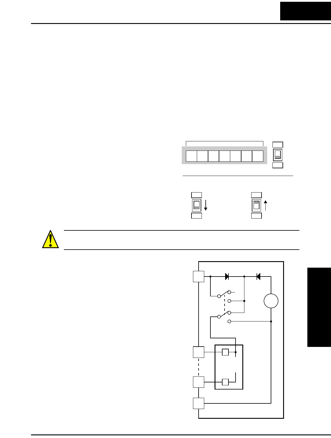
L2002 Inverter
Operations
and Monitoring
4–9
Using Intelligent Input Terminals
Terminals [1], [2], [3], [4], and [5] are identical, programmable inputs for general use.
The input circuits can use the inverter’s internal (isolated) +24V field supply or an
external power supply. This section describes input circuits operation and how to
connect them properly to switches or transistor outputs on field devices.
The L2002 inverter features selectable sinking or sourcing inputs. These terms refer to
the connection to the external switching device—it either sinks current (from the input to
GND) or sources current (from a power source) into the input. Note that the sink/source
naming convention may be different in your particular country or industry. In any case,
the just follow the wiring diagrams in this section for your application.
The inverter has a DIP switch for config-
uring the choice of sinking or sourcing
inputs. To access it, you must remove the
front cover of the inverter housing. In the
figure to the right, the SR/SK switch
(“source/sink switch”) is shown as
located on the circuit board, at the right
end of the logic signal connector.
DO NOT confuse it with the two, larger
configuration switches nearby. The circuit
board has the SR and SK markings above
and below the switch as shown.
CAUTION: Be sure to turn OFF power to the inverter before changing the SR/SK
switch position. Otherwise, damage to the inverter circuitry may occur.
[PCS] Terminal Wiring - The [PCS]
terminal (Programmable Control System
terminal) is named to include various
devices that can connect to the inverter’s
logic inputs. In the figure to the right,
note the [PCS] terminal and the nearby
diodes and DPDT switch. The upper part
of the SR/SK switch selects between
connecting the inverter’s +24V internal
supply to [PCS] or allowing an external
supply power to connect. The lower part
of the SR/SK switch selects between
connecting the input circuit common node
to either Logic GND or the +24V supply.
The wiring diagrams on the following
pages show the four combinations of
using sourcing or sinking inputs, and
using the internal or an external DC
supply.
SR
SK
SR
SK
Legend:
Source
(default)
SR
SK
Sink
Logic inputs
12345L
PCS
L2002
L
24V
+
–
SK
SR
SK
SR
PCS
Input
circuits
1
5
Logic GND
Input common
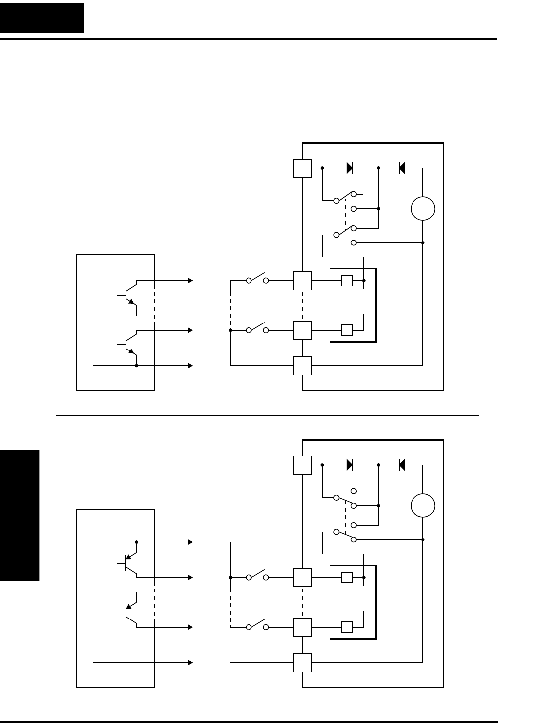
Using Intelligent Input Terminals
Operations
and Monitoring
4–10
The two diagrams below show input wiring circuits using the inverter’s internal +24V
supply. Each diagram shows the connection for simple switches, or for a field device
with transistor outputs. Note that in the lower diagram, it is necessary to connect
terminal [L] only when using the field device with transistors. Be sure to use the correct
SR/SK switch position shown for each wiring diagram.
L2002
L
24V
+
–
SK
SR
SK
SR
PCS
Input
circuits
1
5
Logic GND
1
5
GND
Open collector outputs,
NPN transistors Input
switches
Sinking Inputs, Internal Supply
SR/SK switch = SK position
Field device
L2002
L
24V
+
–
SK
SR
SK
SR
PCS
Input
circuits
1
5
Common,
to [PCS]
1
5
GND
PNP transistor
sourcing outputs
Input
switches
Sourcing Inputs, Internal Supply
SR/SK switch = SR position
Field device
to PNP bias
circuits Logic GND
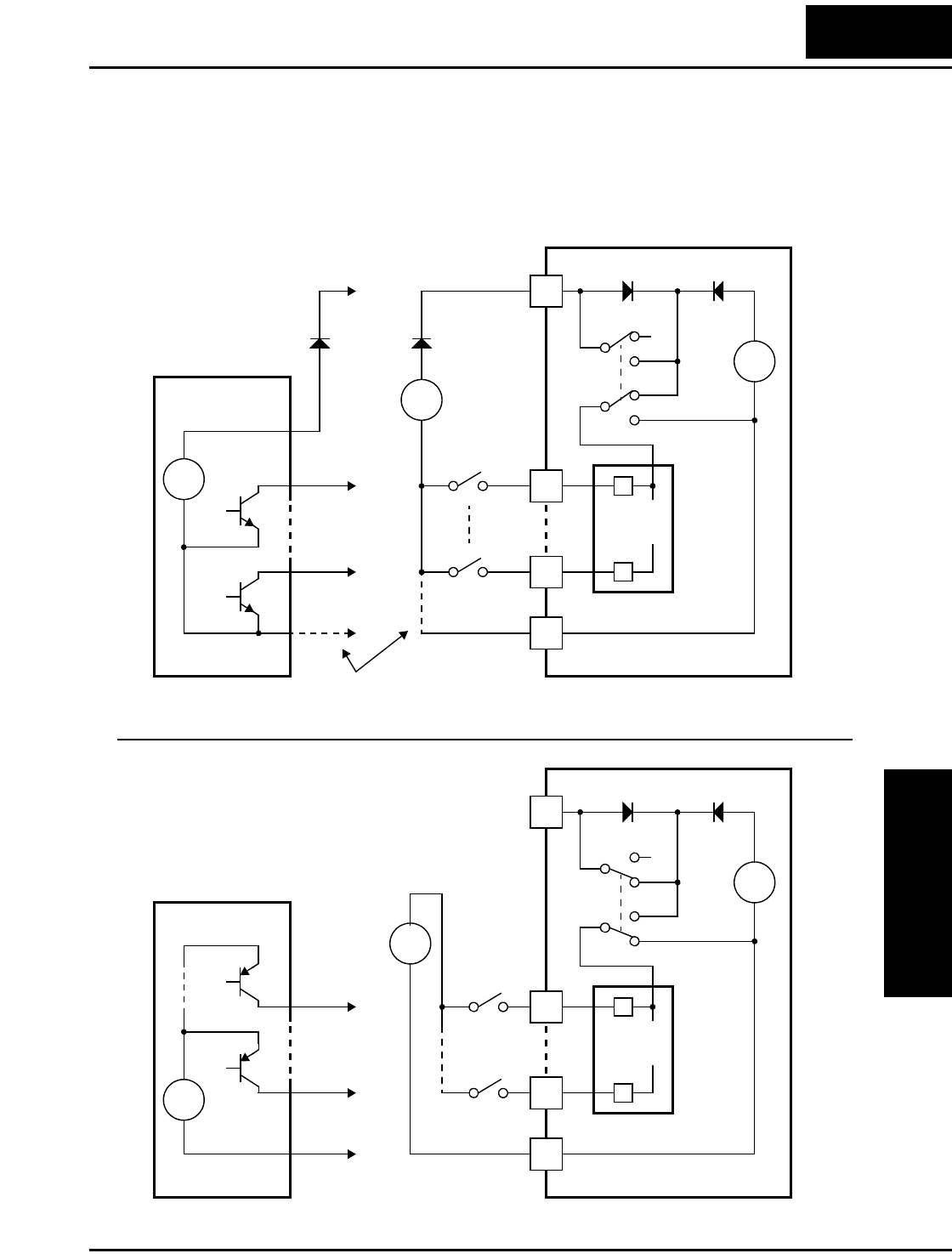
L2002 Inverter
Operations
and Monitoring
4–11
The two diagrams below show input wiring circuits using an external supply. If using the
upper wiring diagram, be sure to use a diode with the external supply. This will prevent a
power supply contention in case the SR/SK switch is accidentally placed in the incorrect
position. Be sure to use the correct SR/SK switch position shown for each wiring
diagram.
L2002
L
24V
+
–
SK
SR
SK
SR
PCS
Input
circuits
1
5
Logic GND
1
5
GND
Open collector outputs,
NPN transistors
Input
switches
Sinking Inputs, External Supply
SR/SK switch = SK position
Field device
L2002
L
24V
+
–
SK
SR
SK
SR
PCS
Input
circuits
1
5
1
5
GND
PNP transistor
sourcing outputs
Input
switches
Sourcing Inputs, External Supply
SR/SK switch = SR position
Field device
Logic GND
24V
+
–
+
–
+V
**
* Note: If the external power supply GND is (optionally)
connected to [L], then install the above diode.
24V
+
–
+
–
24V
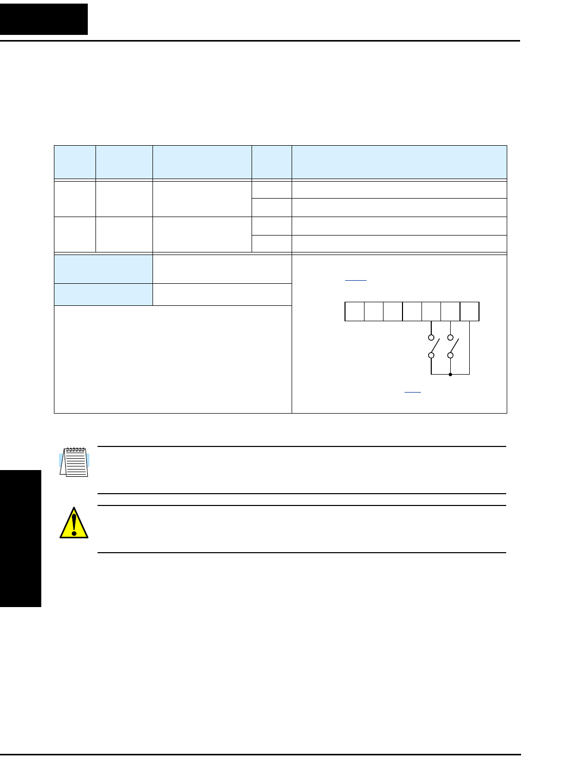
Using Intelligent Input Terminals
Operations
and Monitoring
4–12
Forward Run/Stop and Reverse Run/Stop Commands:
When you input the Run command via the terminal [FW], the inverter executes the
Forward Run command (high) or Stop command (low). When you input the Run
command via the terminal [RV], the inverter executes the Reverse Run command (high)
or Stop command (low).
NOTE: The parameter F004, Keypad Run Key Routing, determines whether the single
Run key issues a Run FWD command or Run REV command. However, it has no effect
on the [FW] and [RV] input terminal operation.
WARNING: If the power is turned ON and the Run command is already active, the
motor starts rotation and is dangerous! Before turning power ON, confirm that the Run
command is not active.
Option
Code
Terminal
Symbol Function Name State Description
00 FW Forward Run/Stop ON Inverter is in Run Mode, motor runs forward
OFF Inverter is in Stop Mode, motor stops
01 RV Reverse Run/Stop ON Inverter is in Run Mode, motor runs reverse
OFF Inverter is in Stop Mode, motor stops
Valid for inputs: C001, C002, C003, C004,
C005
Required settings: A002 = 01
Notes:
•When the Forward Run and Reverse Run
commands are active at the same time, the inverter
enters the Stop Mode.
•When a terminal associated with either [FW] or
[RV] function is configured for normally closed,
the motor starts rotation when that terminal is
disconnected or otherwise has no input voltage.
Example (default input configuration shown—
see page 3–47):
See I/O specs on page 4–6.
FWRV
12345L
PCS
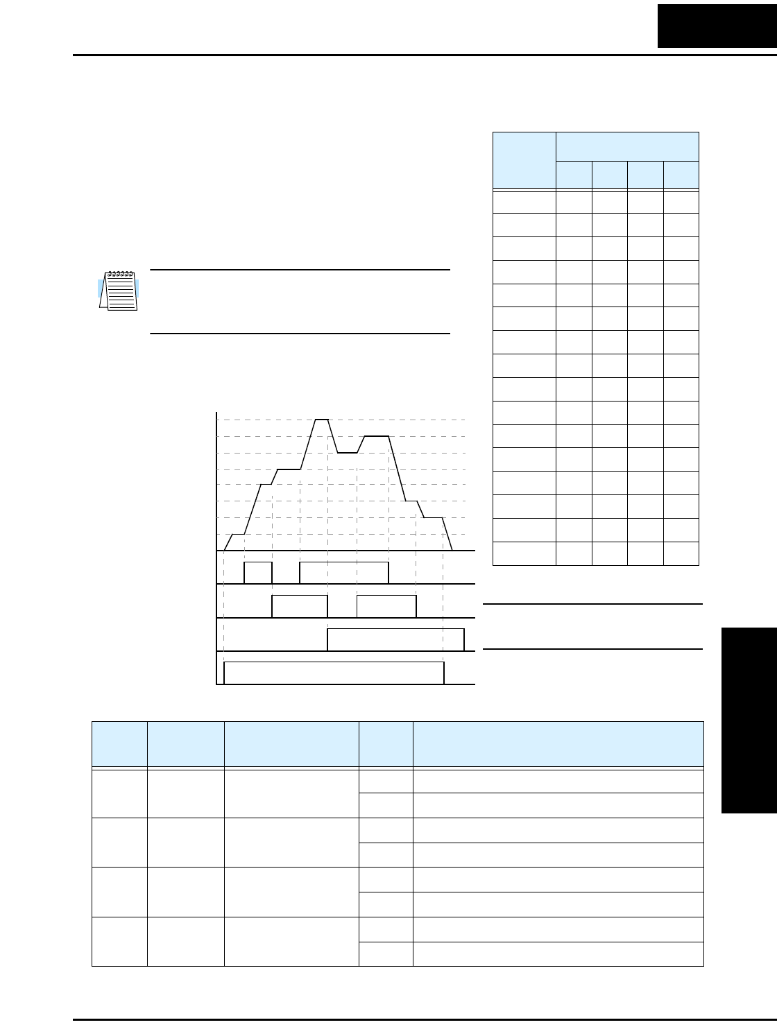
L2002 Inverter
Operations
and Monitoring
4–13
Multi-Speed Select
The inverter can store up to 16 different target
frequencies (speeds) that the motor output uses for
steady-state run condition. These speeds are acces-
sible through programming four of the intelligent
terminals as binary-encoded inputs CF1 to CF4 per
the table to the right. These can be any of the six
inputs, and in any order. You can use fewer inputs
if you need eight or fewer speeds.
Note: When choosing a subset of speeds to use,
always start at the top of the table, and with the
least-significant bit: CF1, CF2, etc.
The example with eight speeds in the figure below
shows how input switches configured for CF1–CF3
functions can change the motor speed in real time.
NOTE: Speed 0 is set by the A020
parameter value.
Multi-
speed
Input Function
CF4 CF3 CF2 CF1
Speed 0 0000
Speed 1 0001
Speed 2 0010
Speed 3 0011
Speed 4 0100
Speed 5 0101
Speed 6 0110
Speed 7 0111
Speed 8 1000
Speed 9 1001
Speed 101010
Speed 111011
Speed 121100
Speed 131101
Speed 141110
Speed 151111
[CF1]
[CF2]
[CF3]
[FWD]
t
Speed
0th
4th
6th
1st
2nd
5th
7th
3rd
1
0
1
0
1
0
1
0
Option
Code
Terminal
Symbol Function Name Input
State Description
02 CF1 Multi-speed Select,
Bit 0 (LSB)
ON Binary encoded speed select, Bit 0, logical 1
OFF Binary encoded speed select, Bit 0, logical 0
03 CF2 Multi-speed Select,
Bit 1
ON Binary encoded speed select, Bit 1, logical 1
OFF Binary encoded speed select, Bit 1, logical 0
04 CF3 Multi-speed Select,
Bit 2
ON Binary encoded speed select, Bit 2, logical 1
OFF Binary encoded speed select, Bit 2, logical 0
05 CF4 Multi-speed Select,
Bit 3 (MSB)
ON Binary encoded speed select, Bit 3, logical 1
OFF Binary encoded speed select, Bit 3, logical 0
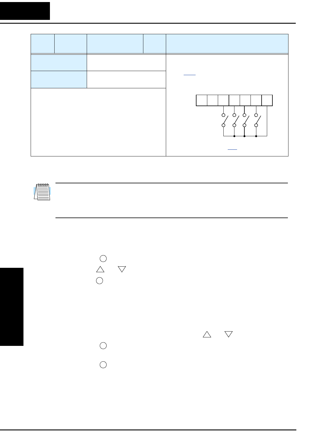
Using Intelligent Input Terminals
Operations
and Monitoring
4–14
While using the multi-speed capability, you can monitor the present frequency with
monitor function D001 during each segment of a multi-speed operation.
NOTE: When using the Multi-speed Select settings CF1 to CF4, do not display parame-
ter F001 or change the value of F001 while the inverter is in Run Mode (motor running).
If it is necessary to check the value of F001 during Run Mode, please monitor D001
instead of F001.
There are two ways to program the speeds into the registers A020 to A035:
1. Standard keypad programming:
a. Select each parameter A020 to A035.
b. Press the key to view the parameter value.
c. Use the and keys to edit the value.
d. Use the key to save the data to memory.
2. Programming using the CF switches. Set the speed by following these steps:
a. Turn the Run command OFF (Stop Mode).
b. Turn inputs ON to select desired Multi-speed. Display the value of F001 on the
digital operator.
c. Set the desired output frequency by pressing the and keys.
d. Press the key once to store the set frequency. When this occurs, F001
indicates the output frequency of Multi-speed n.
e. Press the key once to confirm that the indication is the same as the set
frequency.
f. Repeat operations in 2. a) to 2. e) to set the frequency of other Multi-speeds. It
can be set also by parameters A020 to A035 in the first procedure 1. a) to 1. d).
Valid for inputs: C001, C002, C003, C004,
C005
Required settings: F001, A001 = 02,
A020 to A035
Notes:
•When programming the multi-speed settings, be
sure to press the Store key each time and then set
the next multi-speed setting. Note that when the key
is not pressed, no data will be set.
•When a multi-speed setting more than 50Hz(60Hz)
is to be set, it is necessary to program the maximum
frequency A004 high enough to allow that speed.
Option
Code
Terminal
Symbol Function Name Input
State Description
Example (some CF inputs require input
configuration; some are default inputs—see
page 3–47):
See I/O specs on page 4–6.
CF2
CF3
CF4 CF1
(LSB)(MSB)
12345L
PCS
FUNC.
12
STR
12
STR
FUNC.
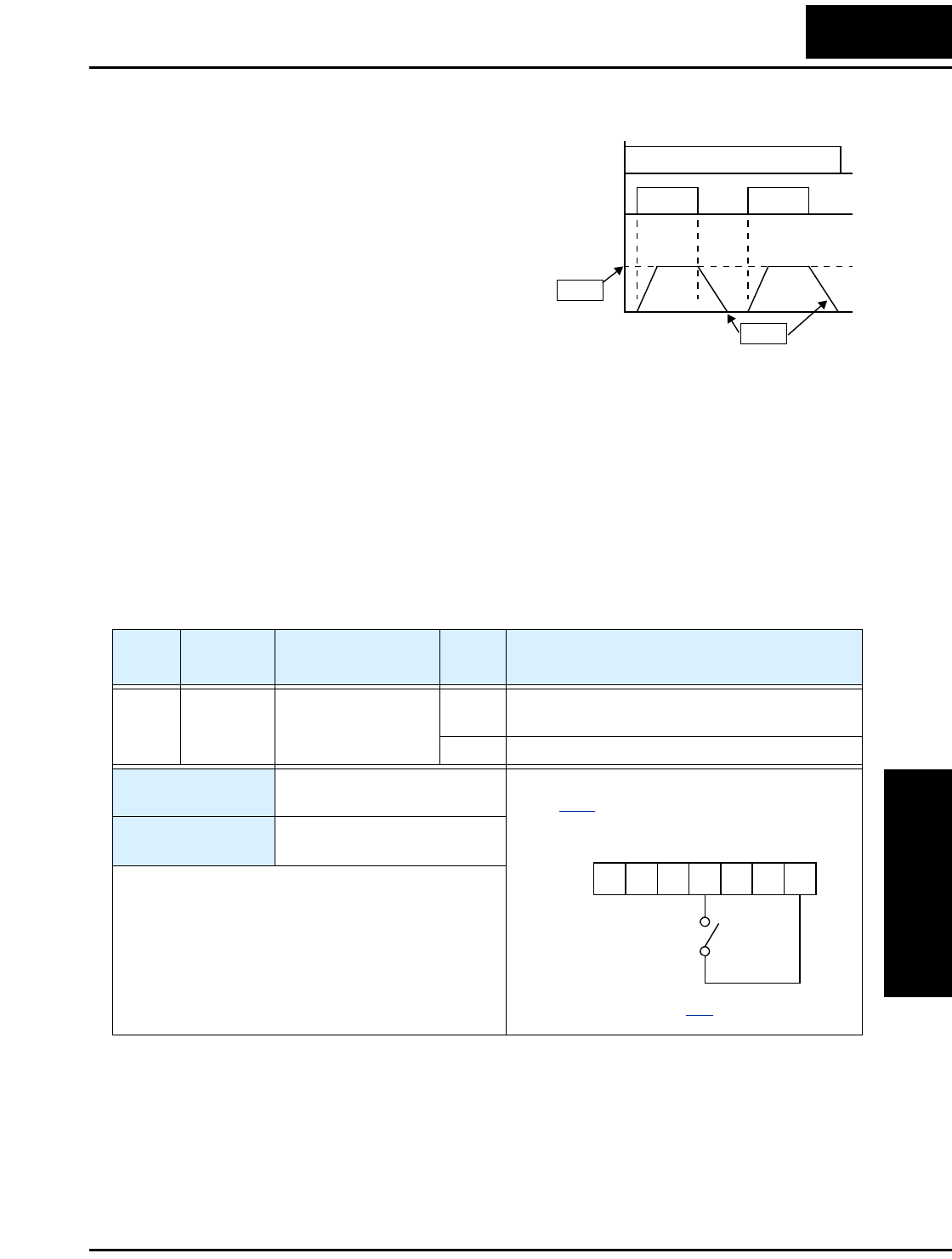
L2002 Inverter
Operations
and Monitoring
4–15
Jogging Command
The Jog input [JG] is used to command the
motor to rotate slowly in small increments for
manual operation. The speed is limited to
10 Hz. The frequency for the jogging opera-
tion is set by parameter A038. Jogging does
not use an acceleration ramp, so we recom-
mend setting the jogging frequency A038 to
5 Hz or less to prevent tripping.
When the terminal [JG] is turned ON and the
Run command is issued, the inverter outputs
the programmed jog frequency to the motor.
To enable the Run key on the digital operator
for jog input, set the value 01(terminal mode)
in A002 (Run command source).
The type of deceleration used to end a motor jog operation is selectable by programming
function A039. The options are:
• 00 Free-run stop (coasting)
• 01 Deceleration (normal level) and stop
• 02 Use DC braking and stop
[JG]
[FW],
[RV]
Jog decel type
Jog
speed
1
0
1
0
t
A038
A039
Option
Code
Terminal
Symbol Function Name Input
State Description
06 JG Jogging ON Inverter is in Run Mode, output to motor runs at
jog parameter frequency
OFF Inverter is in Stop Mode
Valid for inputs: C001, C002, C003, C004,
C005
Required settings: A002= 01, A038 > B082,
A038 > 0, A039
Notes:
•No jogging operation is performed when the set
value of jogging frequency A038 is smaller than the
start frequency B082, or the value is 0 Hz.
•Be sure to stop the motor when switching the
function [JG] ON or OFF.
Example (requires input configuration—see
page 3–47):
See I/O specs on page 4–6.
JG
12345L
PCS
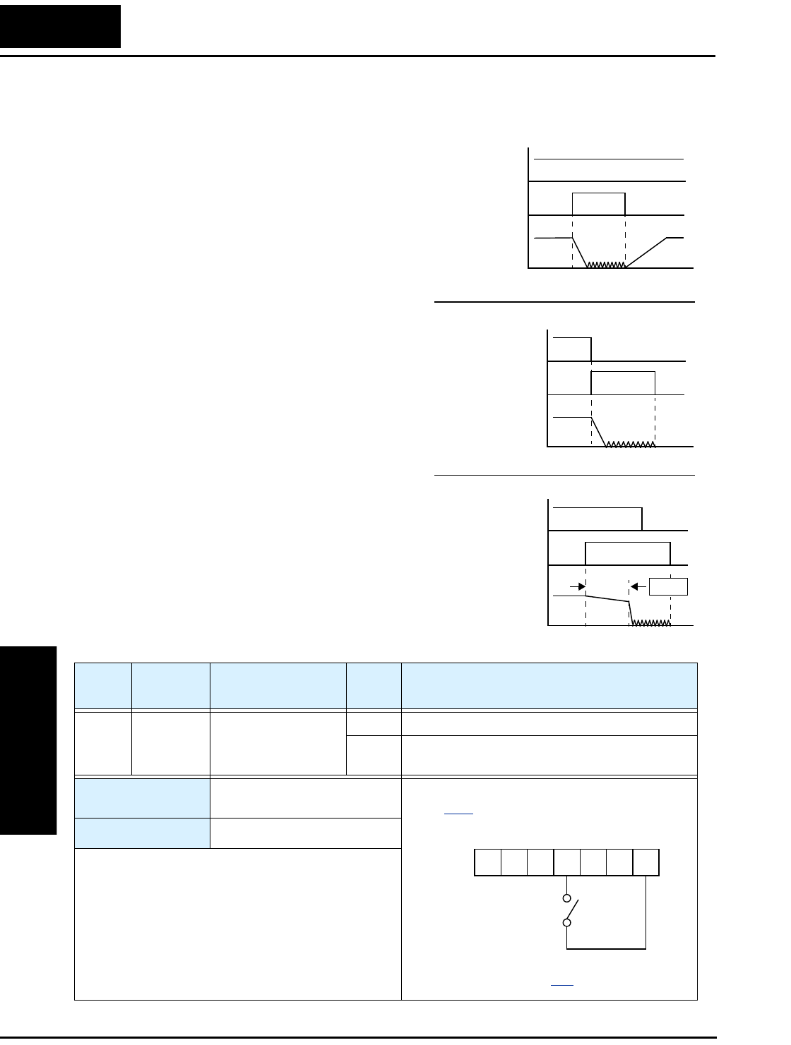
Using Intelligent Input Terminals
Operations
and Monitoring
4–16
External Signal for DC Braking
When the terminal [DB] is turned ON, the
DC braking feature is enabled. Set the follow-
ing parameters when the external DC braking
terminal [DB] is to be used:
• A053 – DC braking delay time setting. The
range is 0.1 to 5.0 seconds.
• A054 – DC braking force setting. The
range is 0 to 100%.
The scenarios to the right help show how DC
braking works in various situations.
1. Scenario 1 – The [FW] or [RV] terminal is
ON. When [DB] is ON, DC braking is
applied. When [DB] is OFF again, the
output frequency ramps to the prior level.
2. Scenario 2 – The Run command is applied
from the operator keypad. When the [DB]
terminal is ON, DC braking is applied.
When the [DB] terminal is OFF again, the
inverter output remains OFF.
3. Scenario 3 – The Run command is applied
from the operator keypad. When the [DB]
terminal is ON, DC braking is applied
after the delay time set by A053 expires.
The motor is in a free-running (coasting)
condition. When the [DB] terminal is OFF
again, the inverter output remains OFF.
Output
frequency
[FW, RV]
[DB]
Scenario 1
Output
frequency
Run command
from operator
Scenario 2
Output
frequency
Scenario 3
[DB]
[DB]
Run command
(from operator)
1
0
1
0
t
t
t
delay
1
0
1
0
1
0
1
0
A053
Option
Code
Terminal
Symbol Function Name Input
State Description
07 DB External DC Braking ON applies DC injection braking during deceleration
OFF does not apply DC injection braking during
deceleration
Valid for inputs: C001, C002, C003, C004,
C005
Required settings: A053, A054
Notes:
•Do not use the [DB] input continuously or for a
long time when the DC braking force setting A054
is high (depends on the motor application).
•Do not use the [DB] feature for continuous or high
duty cycle as a holding brake. The [DB] input is
designed to improve stopping performance. Use a
mechanical brake for holding a stop position.
Example (requires input configuration—see
page 3–47):
See I/O specs on page 4–6.
DB
12345L
PCS
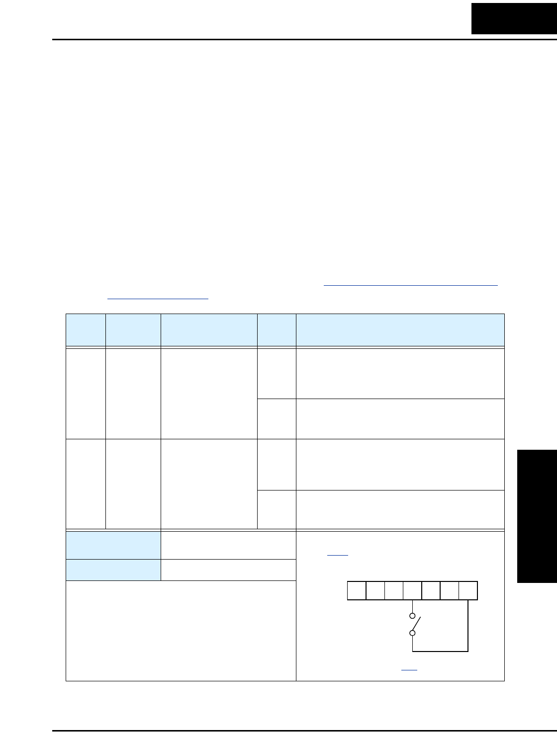
L2002 Inverter
Operations
and Monitoring
4–17
Set Second Motor and Special-Set Second Motor
If you assign the [SET] or [S-ST] function to an intelligent input terminal, you can select
between two sets of motor parameters. The second parameters store an alternate set of
motor characteristics. Two type of inputs are available:
• Set Second Motor - The inverter can select a different motor only in Stop Mode.
• Special-Set Second Motor - The inverter can select a different motor in either Stop
Mode or Run Mode. The following parameter pairs can be alternately selected during
Run Mode: A020/A220, F002/F202, F003/F203, A042/A242, A043/A243, A061/
A261, A062/A262, A092/A292, A093/A293, A094/A294, A095/A295, A096/A296
When the terminal [SET] or [S-ST] is turned ON, the inverter will use the second set of
parameters to generate the frequency output to the motor. When changing the state of the
[SET] input terminal, the change will not take effect until the inverter is stopped.
When you turn ON the [SET] or [S-ST] input, the inverter operates per the second set of
parameters. When the terminal is turned OFF, the output function returns to the original
settings (first set of motor parameters). Refer to “Configuring the Inverter for Multiple
Motors” on page 4–58 for details.
Option
Code
Terminal
Symbol Function Name Input
State Description
08 SET Set (select) 2nd
Motor Data
ON causes the inverter to use the 2nd set of motor
parameters for generating the frequency output
to motor. The selection of 1st or 2nd motor is
available only in Stop Mode.
OFF causes the inverter to use the 1st (main) set of
motor parameters for generating the frequency
output to motor
53 S-ST Special-Set (select)
2nd Motor Data
ON causes the inverter to use the 2nd set of motor
parameters for generating the frequency output
to motor. The selection of 1st or 2nd motor is
available in Stop Mode or Run Mode.
OFF causes the inverter to use the 1st (main) set of
motor parameters for generating the frequency
output to motor
Valid for inputs: C001, C002, C003, C004,
C005
Required settings: (none)
Notes:
•If the terminal state for [SET] is changed while the
inverter is running, the inverter continues using the
current set of parameters until the inverter is
stopped.
•You cannot configure the inverter to use [SET] and
[S-ST] terminals at the same time.
Example (requires input configuration—see
page 3–47):
See I/O specs on page 4–6.
12345L
PCS
SET
(or S-ST)
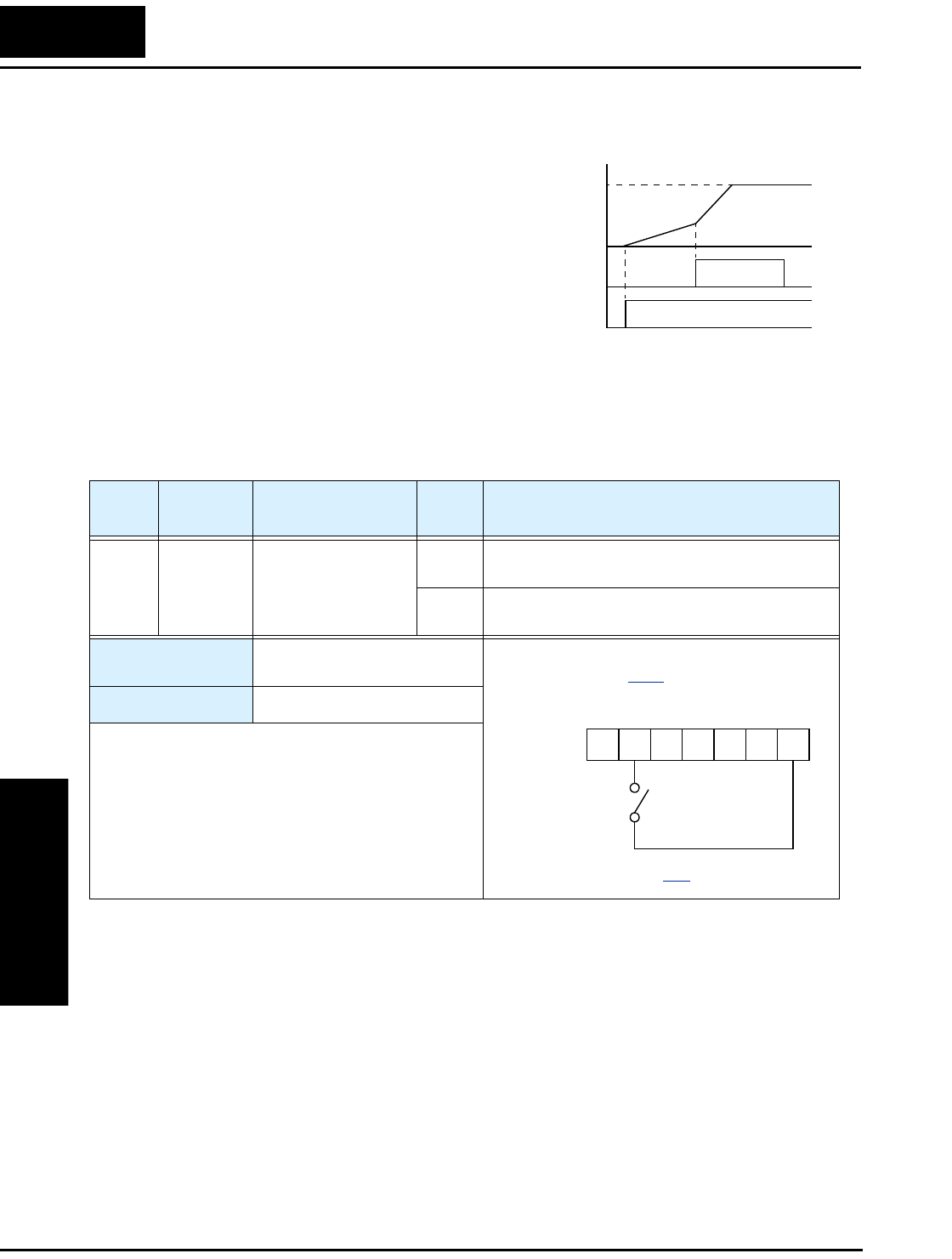
Using Intelligent Input Terminals
Operations
and Monitoring
4–18
Two-stage Acceleration and Deceleration
When terminal [2CH] is turned ON, the
inverter changes the rate of acceleration and
deceleration from the initial settings (F002
and F003) to use the second set of accelera-
tion/deceleration values. When the terminal is
turned OFF, the inverter is returned to the
original acceleration and deceleration time
(F002 acceleration time 1, and F003 decelera-
tion time 1). Use A092 (acceleration time 2)
and A0093 (deceleration time 2) to set the
second stage acceleration and deceleration
times.
In the graph shown above, the [2CH] becomes active during the initial acceleration. This
causes the inverter to switch from using acceleration 1 (F002) to acceleration 2 (A092).
Output
frequency
[FW],
[RV]
[2CH]
t
target
frequency
second
initial
1
0
1
0
Option
Code
Terminal
Symbol Function Name Input
State Description
09 2CH Two-stage Accelera-
tion and Deceleration
ON Frequency output uses 2nd-stage acceleration
and deceleration values
OFF Frequency output uses the initial acceleration 1
and deceleration 1 values
Valid for inputs: C001, C002, C003, C004,
C005
Required settings: A092, A093, A094=00
Notes:
•Function A094 selects the method for second stage
acceleration. It must be set = 00 to select the input
terminal method in order for the [2CH] terminal
assignment to operate.
Example (default input configuration
shown—see page 3–47):
See I/O specs on page 4–6.
–FU models
2CH
12345L
PCS
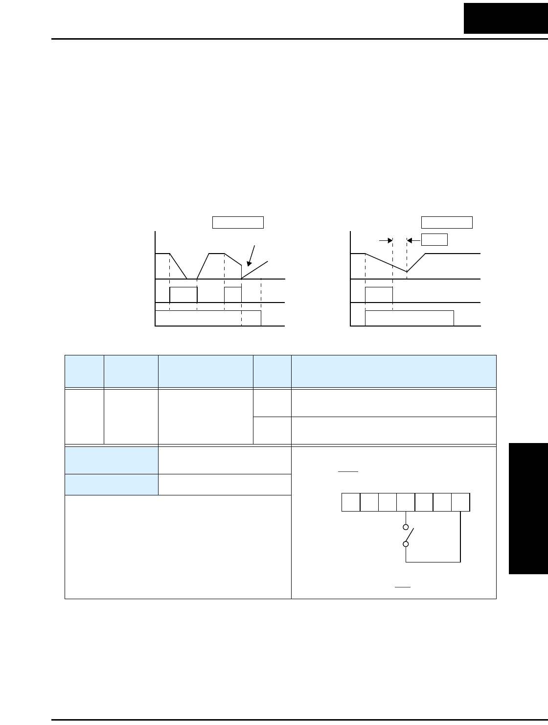
L2002 Inverter
Operations
and Monitoring
4–19
Free-run Stop
When the terminal [FRS] is turned ON, the inverter stops the output and the motor enters
the free-run state (coasting). If terminal [FRS] is turned OFF, the output resumes sending
power to the motor if the Run command is still active. The free-run stop feature works
with other parameters to provide flexibility in stopping and starting motor rotation.
In the figure below, parameter B088 selects whether the inverter resumes operation from
0 Hz (left graph) or the current motor rotation speed (right graph) when the [FRS]
terminal turns OFF. The application determines the best setting.
Parameter B003 specifies a delay time before resuming operation from a free-run stop.
To disable this feature, use a zero delay time.
Motor
speed
[FW],
[RV]
Zero-frequency start
Motor
speed
Resume from motor speed
wait time
B088 =00 B088 =01
1
0tt
FRS FRS
[FW],
[RV]
1
0
1
0
1
0
B003
Option
Code
Terminal
Symbol Function Name Input
State Description
11 FRS Free-run Stop ON Causes output to turn OFF, allowing motor to
free run (coast) to stop
OFF Output operates normally, so controlled deceler-
ation stops motor
Valid for inputs: C001, C002, C003, C004,
C005
Required settings: B003, B088, C011 to C015
Notes:
•When you want the [FRS] terminal to be active low
(normally closed logic), change the setting (C011
to C015) that corresponds to the input (C001 to
C005) that is assigned the [FRS] function.
Example (requires input configuration—
see page 3–47):
See I/O specs on page 4–6.
FRS
12345L
PCS
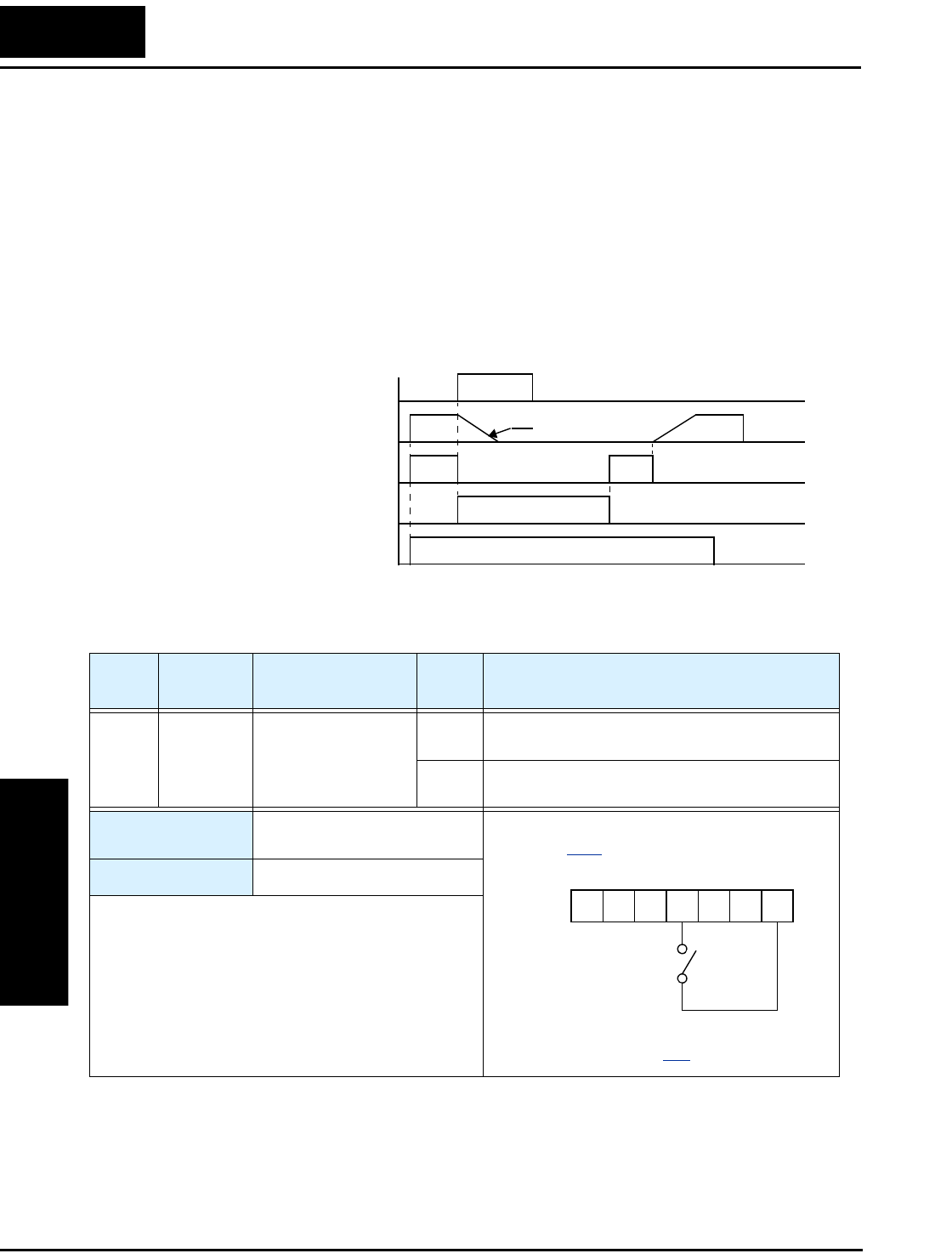
Using Intelligent Input Terminals
Operations
and Monitoring
4–20
External Trip
When the terminal [EXT] is turned ON, the inverter enters the trip state, indicates error
code E12, and stops the output. This is a general purpose interrupt type feature, and the
meaning of the error depends on what you connect to the [EXT] terminal. Even if the
[EXT] input is turned OFF, the inverter remains in the trip state. You must reset the
inverter or cycle power to clear the error, returning the inverter to the Stop Mode.
In the graph below, the [EXT] input turns ON during normal Run Mode operation. The
inverter lets the motor free-run to a stop, and the alarm output turns ON immediately.
When the operator initiates a Reset command, the alarm and error are cleared. When the
Reset is turned OFF, the motor begins rotation since the Run command is already active.
[EXT] terminal
RUN command [FW, RV]
[RS] terminal
Motor revolution speed
Alarm output terminal
t
free run
1
0
1
0
1
0
1
0
1
0
Option
Code
Terminal
Symbol Function Name Input
State Description
12 EXT External Trip ON When assigned input transitions OFF to ON,
inverter latches trip event and displays E12
OFF No trip event for ON to OFF, any recorded trip
events remain in history until Reset
Valid for inputs: C001, C002, C003, C004,
C005
Required settings: (none)
Notes:
•If the USP (Unattended Start Protection) feature is
in use, the inverter will not automatically restart
after cancelling the EXT trip event. In that case, it
must receive either another Run command (OFF-to-
ON transition), a keypad Reset command, or an
[RS] intelligent terminal input signal.
Example (requires input configuration—
see page 3–47):
See I/O specs on page 4–6.
EXT
12345L
PCS
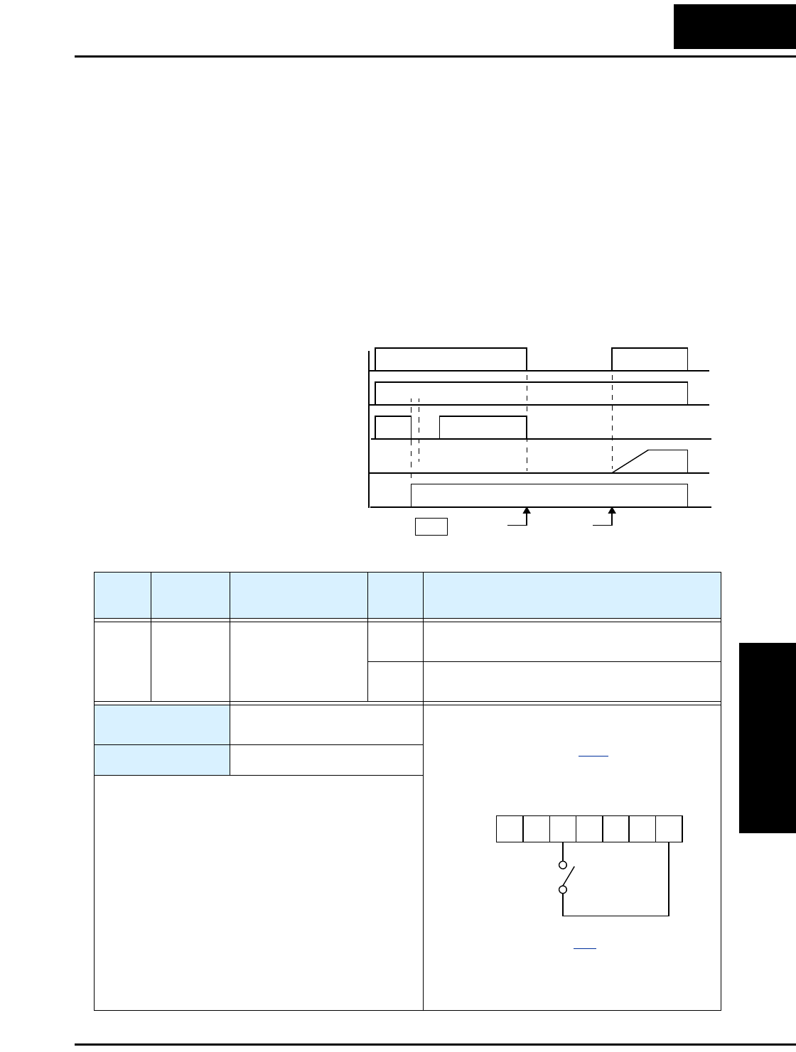
L2002 Inverter
Operations
and Monitoring
4–21
Unattended Start Protection
If the Run command is already set when power is turned ON, the inverter starts running
immediately after powerup. The Unattended Start Protection (USP) function prevents
that automatic startup, so that the inverter will not run without outside intervention.
When USP is active and you need to reset an alarm and resume running, either turn the
Run command OFF, or perform a reset operation by the terminal [RS] input or the
keypad Stop/reset key.
In the figure below, the [UPS] feature is enabled. When the inverter power turns ON, the
motor does not start, even though the Run command is already active. Instead, it enters
the USP trip state, and displays E13 error code. This requires outside intervention to
reset the alarm by turning OFF the Run command per this example (or applying a reset).
Then the Run command can turn ON again and start the inverter output.
Inverter output frequency
Inverter power supply
[USP] terminal
Alarm output terminal
RUN command [FW, RV]
Run
command
Alarm
cleared
Alarm
display E13 t
1
0
1
0
1
0
1
0
1
0
Events:
Option
Code
Terminal
Symbol Function Name Input
State Description
13 USP Unattended Start
Protection
ON On powerup, the inverter will not resume a Run
command (mostly used in the US)
OFF On powerup, the inverter will resume a Run
command that was active before power loss
Valid for inputs: C001, C002, C003, C004,
C005
Required settings: (none)
Notes:
•Note that when a USP error occurs and it is
canceled by a reset from a [RS] terminal input, the
inverter restarts running immediately.
•Even when the trip state is canceled by turning the
terminal [RS] ON and OFF after an under voltage
protection E09 occurs, the USP function will be
performed.
•When the running command is active immediately
after the power is turned ON, a USP error will
occur. When this function is used, wait for at least
three (3) seconds after the powerup to generate a
Run command.
Example (default input configuration shown for
–FU models; –FE and –FR models require input
configuration—see page 3–47):
See I/O specs on page 4–6.
USP
12345L
PCS
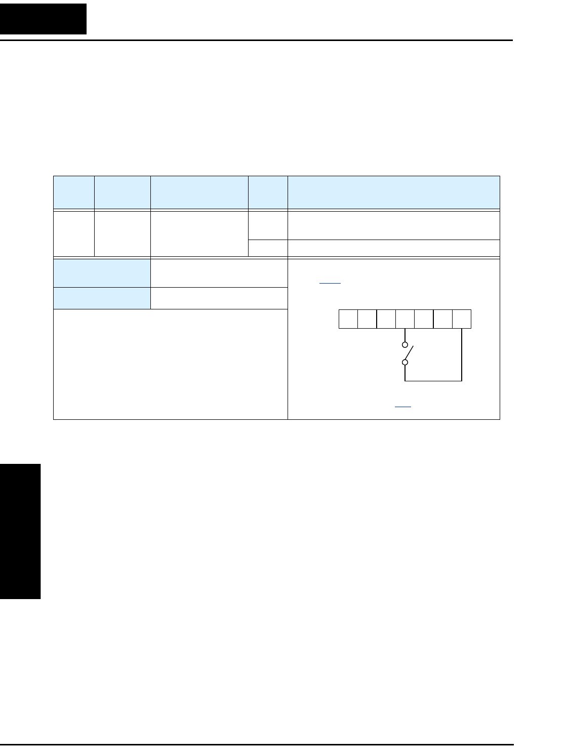
Using Intelligent Input Terminals
Operations
and Monitoring
4–22
Software Lock
When the terminal [SFT] is turned ON, the data of all the parameters and functions
(except the output frequency, depending on the setting of B031) is locked (prohibited
from editing). When the data is locked, the keypad keys cannot edit inverter parameters.
To edit parameters again, turn OFF the [SFT] terminal input.
Use parameter B031 to select whether the output frequency is excluded from the lock
state or is locked as well.
Option
Code
Terminal
Symbol Function Name Input
State Description
15 SFT Software Lock ON The keypad and remote programming devices
are prevented from changing parameters
OFF The parameters may be edited and stored
Valid for inputs: C001, C002, C003, C004,
C005
Required settings: B031 (excluded from lock)
Notes:
•When the [SFT] terminal is turned ON, only the
output frequency can be changed.
•Software lock can include the output frequency by
setting B031.
•Software lock by the operator is also possible
without the [SFT] terminal being used (B031).
Example (requires input configuration—see
page 3–47):
See I/O specs on page 4–6.
SFT
12345L
PCS

L2002 Inverter
Operations
and Monitoring
4–23
Analog Input Current/Voltage Select
The [AT] terminal selects whether the inverter uses the voltage [O] or current [OI] input
terminals for external frequency control. When intelligent input [AT] is ON, you can set
the output frequency by applying a current input signal at [OI]-[L]. When the [AT] input
is OFF, you can apply a voltage input signal at [O]-[L] to set the output frequency. Note
that you must also set parameter A001 = 01 to enable the analog terminal set for control-
ling the inverter frequency.
Option
Code
Terminal
Symbol Function Name Input
State Description
16 AT Analog Input
Voltage/current
Select
ON Terminal OI is enabled for current input (uses
terminal L for power supply return)
OFF Terminal O is enabled for voltage input (uses
terminal L for power supply return)
Valid for inputs: C001, C002, C003, C004,
C005
Required settings: A001 = 01
Notes:
•If the [AT] option is not assigned to any intelligent
input terminal, then inverter uses the algebraic sum
of both the voltage and current inputs for the
frequency command (and A001=01).
•When using either the analog current and voltage
input terminal, make sure that the [AT] function is
allocated to an intelligent input terminal.
•Be sure to set the frequency source setting
A001=01 to select the analog input terminals.
Example (default input configuration shown
for –FU models; –FE models require input
configuration—see page 3–47):
See I/O specs on page 4–6.
AT
12345L
PCS
+ –
4-20 mA, AT=ON
0-10 V, AT=OFF
LH O
OIAM
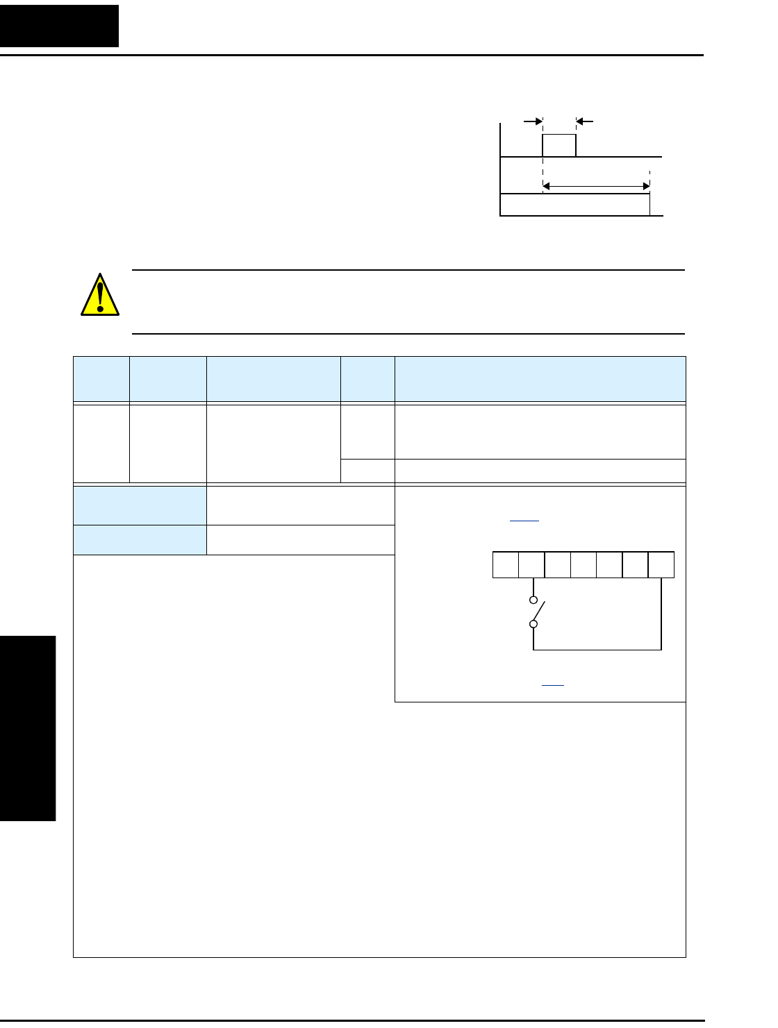
Using Intelligent Input Terminals
Operations
and Monitoring
4–24
Reset Inverter
The [RS] terminal causes the inverter to
execute the reset operation. If the inverter is
in Trip Mode, the reset cancels the Trip state.
When the signal [RS] is turned ON and OFF,
the inverter executes the reset operation. The
minimum pulse width for [RS] must be 12 ms
or greater. The alarm output will be cleared
within 30 ms after the onset of the Reset command.
WARNING: After the Reset command is given and the alarm reset occurs, the motor
will restart suddenly if the Run command is already active. Be sure to set the alarm reset
after verifying that the Run command is OFF to prevent injury to personnel.
[RS]
Alarm
signal
12 ms
minimum
t
1
0
approx. 30 ms
1
0
Option
Code
Terminal
Symbol Function Name Input
State Description
18 RS Reset Inverter ON The motor output is turned OFF, the Trip Mode
is cleared (if it exists), and powerup reset is
applied
OFF Normal power-ON operation
Valid for inputs: C001, C002, C003, C004,
C005
Required settings: (none)
Notes:
•When the control terminal [RS] input is already ON
at powerup for more than 4 seconds, the remote
operator display is “R-ERROR COMM<2>” (the
display of the digital operator is – – –. However,
the inverter has no error. To clear the digital
operator error, turn OFF the terminal [RS] input
and press one of the operator keys.
•Pressing the Stop/Reset key of the digital operator can generate a reset operation only when an alarm
occurs.
•A terminal configured with the [RS] function can only be configured for normally open operation. The
terminal cannot be used in the normally closed contact state.
•When input power is turned ON, the inverter performs the same reset operation as it does when a pulse
on the [RS] terminal occurs.
•The Stop/Reset key on the inverter is only operational for a few seconds after inverter powerup when a
hand-held remote operator is connected to the inverter.
•If the [RS] terminal is turned ON while the motor is running, the motor will be free running (coasting).
•If you are using the output terminal OFF delay feature (any of C145, C147, C149 > 0.0 sec.), the [RS]
terminal affects the ON-to-OFF transition slightly. Normally (without using OFF delays), the [RS]
input causes the motor output and the logic outputs to turn OFF together, immediately. However, when
any output uses an OFF delay, then after the [RS] input turns ON, that output will remain ON for an
additional 1 sec. period (approximate) before turning OFF.
Example (default input configurations
shown—see page 3–47):
See I/O specs on page 4–6.
–FE
models
RS
12345L
PCS
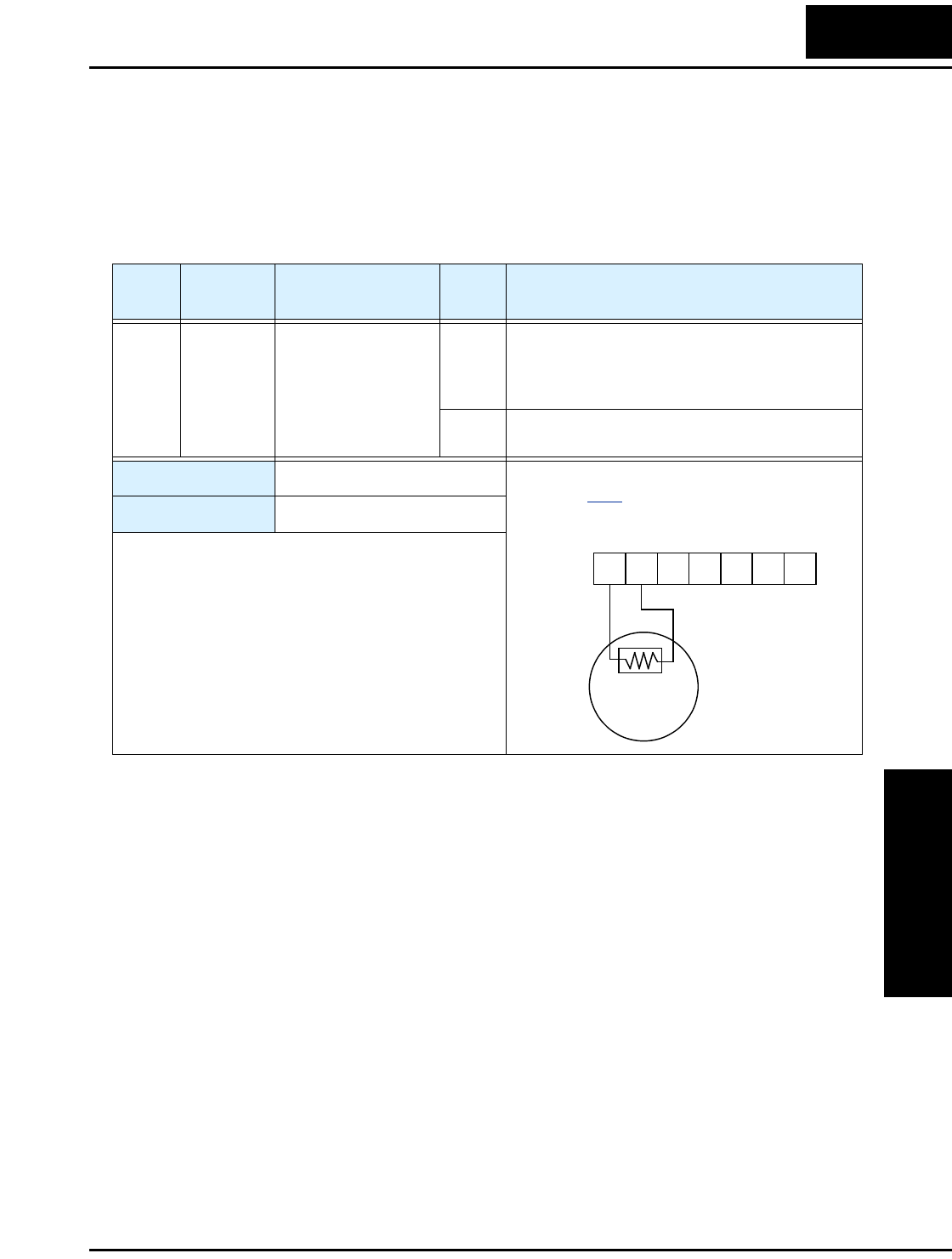
L2002 Inverter
Operations
and Monitoring
4–25
Thermistor Thermal Protection
Motors that are equipped with a PTC thermistor can be protected from overheating.
Input terminal [5] has the unique ability to sense a thermistor resistance. When the resis-
tance value of the thermistor connected to terminal [PTC] at [5] and [L] is more than
3k Ω ±10%, the inverter enters the Trip Mode, turns OFF the output to the motor, and
indicates the trip status E35. Use this function to protect the motor from overheating
Option
Code
Terminal
Symbol Function Name Input
State Description
19 PTC Thermistor Thermal
Protection
Sensor When a thermistor is connected to terminals [5]
and [L], the inverter checks for over-temperature
and will cause trip (E35) and turn OFF the
output to the motor
Open An open circuit in the thermistor causes a trip,
and the inverter turns OFF the output
Valid for inputs: C005 only
Required settings: C085
Notes:
•Be sure the thermistor is connected to terminals [5]
and [L]. If the resistance is above the threshold the
inverter will trip. When the motor cools down
enough, the thermistor resistance will change
enough to permit you to clear the error. Press the
STOP/Reset key to clear the error.
Example (requires input configuration—
see page 3–47):
PTC
thermistor
MOTOR
12345L
PCS
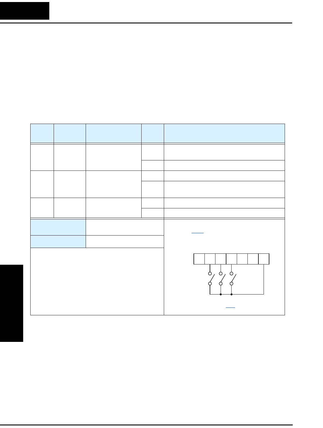
Using Intelligent Input Terminals
Operations
and Monitoring
4–26
Three-wire Interface Operation
The 3-wire interface is an industry standard motor control interface. This function uses
two inputs for momentary contact start/stop control, and a third for selecting forward or
reverse direction. To implement the 3-wire interface, assign 20 [STA] (Start), 21 [STP]
(Stop), and 22 [F/R] (Forward/Reverse) to three of the intelligent input terminals. Use a
momentary contact for Start and Stop. Use a selector switch, such as SPST for the
Forward/Reverse input. Be sure to set the operation command selection A002=01 for
input terminal control of motor.
If you have a motor control interface that needs logic-level control (rather than momen-
tary pulse control), use the [FW] and [RV] inputs instead.
Option
Code
Terminal
Symbol Function Name Input
State Description
20 STA Start Motor ON Start motor rotation on momentary contact (uses
acceleration profile)
OFF No change to motor operation
21 STP Stop Motor ON No change to motor operation
OFF Stop motor rotation on momentary contact (uses
deceleration profile)
22 F/R Forward/Reverse ON Select reverse direction of rotation
OFF Select forward direction of rotation
Valid for inputs: C001, C002, C003, C004,
C005
Required settings: A002 = 01
Notes:
•The STP logic is inverted. Normally the switch will
be closed, so you open the switch to stop. In this
way, a broken wire causes the motor to stop
automatically (safe design).
•When you configure the inverter for 3-wire inter-
face control, the dedicated [FW] terminal is
automatically disabled. The [RV] intelligent
terminal assignment is also disabled.
Example (requires input configuration—
see page 3–47):
See I/O specs on page 4–6.
STP
STAF/R
12345L
PCS
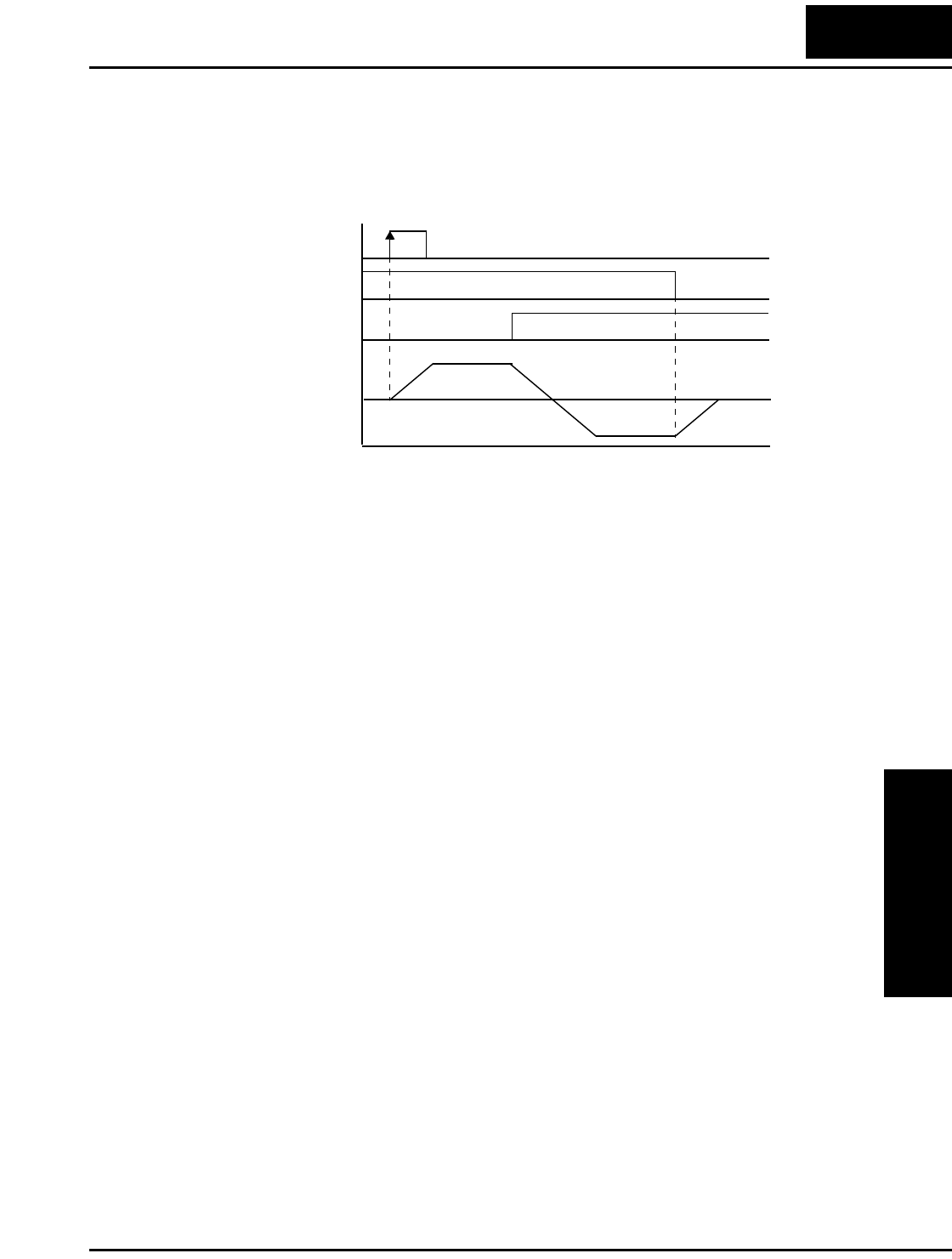
L2002 Inverter
Operations
and Monitoring
4–27
The diagram below shows the use of 3-wire control. STA (Start Motor) is an edge-sensi-
tive input; an OFF-to-ON transition gives the Start command. The control of direction is
level-sensitive, and the direction may be changed at any time. STP (Stop Motor) is also a
level-sensitive input.
Motor revolu-
tion speed
[STA] terminal
[F/R] terminal
[STP terminal]
1
0
t
1
0
1
0
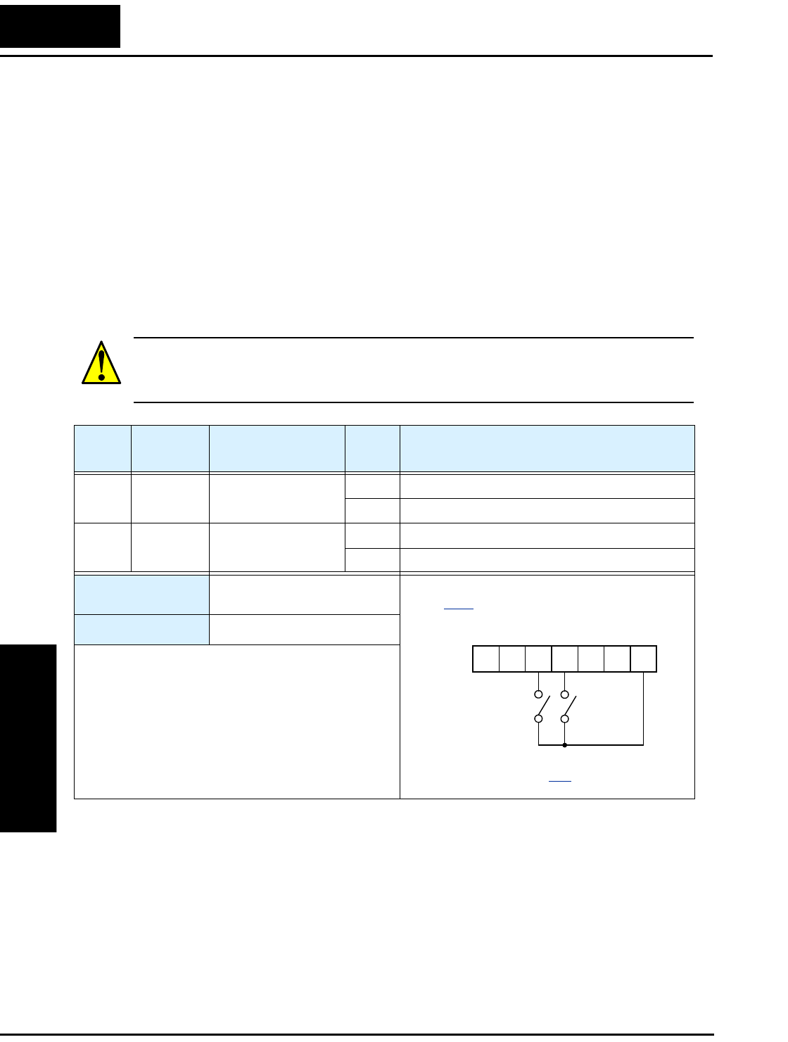
Using Intelligent Input Terminals
Operations
and Monitoring
4–28
PID ON/OFF and PID Clear
The PID loop function is useful for controlling motor speed to achieve constant flow,
pressure, temperature, etc. in many process applications. The PID Disable function
temporarily suspends PID loop execution via an intelligent input terminal. It overrides
the parameter A071 (PID Enable) to stop PID execution and return to normal motor
frequency output characteristics. the use of PID Disable on an intelligent input terminal
is optional. Of course, any use of the PID loop control requires setting PID Enable
function A071=01.
The PID Clear function forces the PID loop integrator sum = 0. So, when you turn ON
an intelligent input configured as [PIDC], the integrator sum is reset to zero. This is
useful when switching from manual control to PID loop control and the motor is
stopped.
CAUTION: Be careful not to turn PID Clear ON and reset the integrator sum when the
inverter is in Run Mode (output to motor is ON). Otherwise, this could cause the motor
to decelerate rapidly, resulting in a trip.
Option
Code
Terminal
Symbol Function Name Input
State Description
23 PID PID Disable ON Disables PID loop execution
OFF Allows PID loop execution if A71=01
24 PIDC PID Clear ON Force the value of the integrator to zero
OFF No change to PID loop execution
Valid for inputs: C001, C002, C003, C004,
C005
Required settings: A071
Notes:
•The use of [PID] and [PIDC] terminals are
optional. Use A071=01 if you want PID loop
control enabled all the time.
•Do not enable/disable PID control while the motor
is running (inverter is in Run Mode).
•Do not turn ON the [PIDC] input while the motor is
running (inverter is in Run Mode).
Example (requires input configuration—see
page 3–47):
See I/O specs on page 4–6.
PID
PIDC
12345L
PCS
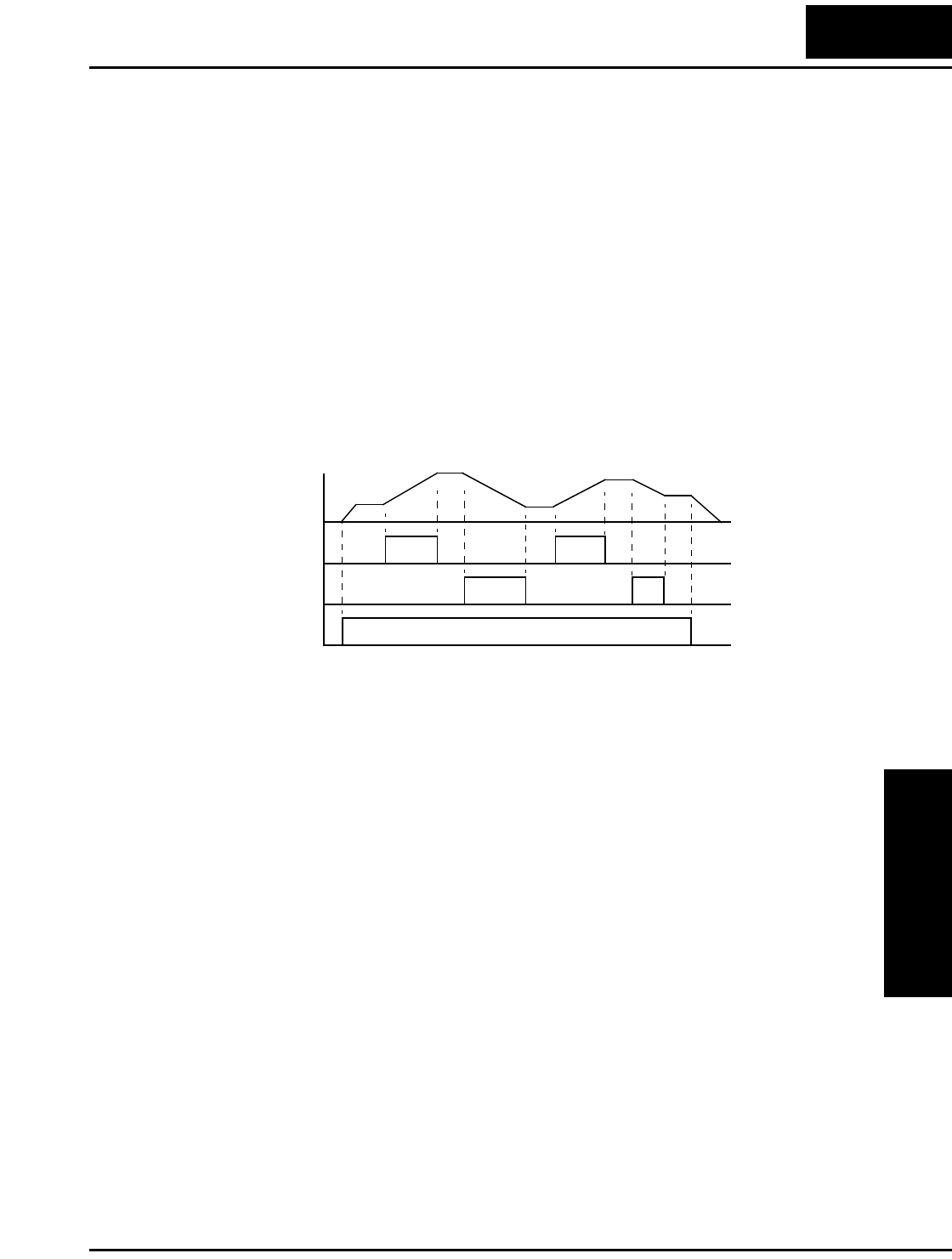
L2002 Inverter
Operations
and Monitoring
4–29
Remote Control Up and Down Functions
The [UP] [DWN] terminal functions can adjust the output frequency for remote control
while the motor is running. The acceleration time and deceleration time of this function
is same as normal operation ACC1 and DEC1 (2ACC1,2DEC1). The input terminals
operate according to these principles:
• Acceleration - When the [UP] contact is turned ON, the output frequency accelerates
from the current value. When it is turned OFF, the output frequency maintains its
current value at that moment.
• Deceleration - When the [DWN] contact is turned ON, the output frequency deceler-
ates from the current value. When it is turned OFF, the output frequency maintains its
current value at that moment.
In the graph below, the [UP] and [DWN] terminals activate while the Run command
remains ON. The output frequency responds to the [UP] and [DWN] commands.
Output
frequency
[UP]
[FW], [RV]
[DWN]
1
0
t
1
0
1
0
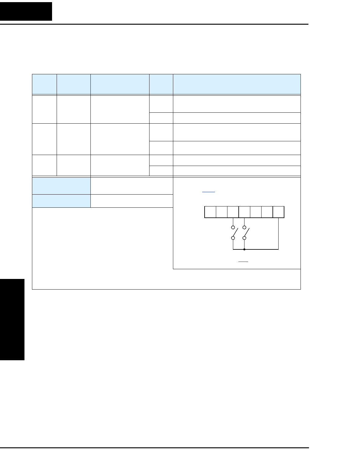
Using Intelligent Input Terminals
Operations
and Monitoring
4–30
It is possible for the inverter to retain the frequency set from the [UP] and [DWN] termi-
nals through a power loss. Parameter C101 enables/disables the memory. If disabled, the
inverter retains the last frequency before an UP/DWN adjustment. Use the [UDC]
terminal to clear the memory and return to the original set output frequency.
Option
Code
Terminal
Symbol Function Name Input
State Description
27 UP Remote Control
UP Function (motor-
ized speed pot.)
ON Accelerates (increases output frequency) motor
from current frequency
OFF Output to motor operates normally
28 DWN Remote Control
DOWN Function
(motorized speed
pot.)
ON Decelerates (decreases output frequency) motor
from current frequency
OFF Output to motor operates normally
29 UDC Remote Control Data
Clear
ON Clears the Up/down frequency memory
OFF No effect on Up/down memory
Valid for inputs: C001, C002, C003, C004,
C005
Required settings: A001 = 02
Notes:
•This feature is available only when the frequency
command source is programmed for operator
control. Confirm A001 is set to 02.
•This function is not available when [JG] is in use.
•The range of output frequency is 0 Hz to the value
in A004 (maximum frequency setting).
•The minimum ON time of [UP] and [DWN] is 50 ms.
•This setting modifies the inverter speed from using F001 output frequency setting as a starting point.
Example (requires input configuration—
see page 3–47):
See I/O specs on page 4–6.
DWN UP
12345L
PCS
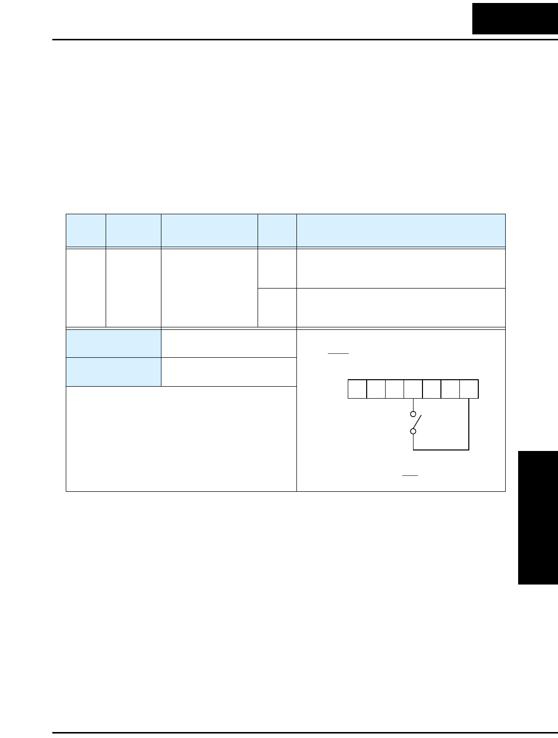
L2002 Inverter
Operations
and Monitoring
4–31
Force Operation from Digital Operator
This function permits a digital operator interface to override the following two settings
in the inverter:
• A001 - Frequency source setting
• A002 - Run command source setting
When using the [OPE] terminal input, typically A001 and A002 are configured for
sources other than the digital operator interface for the output frequency and Run
command sources, respectively. When the [OPE] input is ON, then user has immediate
command of the inverter, to start or stop the motor and to set the speed.
Option
Code
Terminal
Symbol Function Name Input
State Description
31 OPE Force Operation
from Digital
Operator
ON Forces the operator interface to override:
A001 - Frequency Source Setting, and
A002 - Run Command Source Setting
OFF Parameters A001 and A002 are in effect again,
for the frequency source and the Run command
source, respectively
Valid for inputs: C001, C002, C003, C004,
C005
Required settings: A001 (set not equal to 00)
A002 (set not equal to 02)
Notes:
•When changing the [OPE] state during Run Mode
(inverter is driving the motor), the inverter will stop
the motor before the new [OPE] state takes effect.
•If the [OPE] input turns ON and the digital operator
gives a Run command while the inverter is already
running, the inverter stops the motor. Then the
digital operator can control the motor.
Example (requires input configuration—see
page 3–47):
See I/O specs on page 4–6.
OPE
12345L
PCS
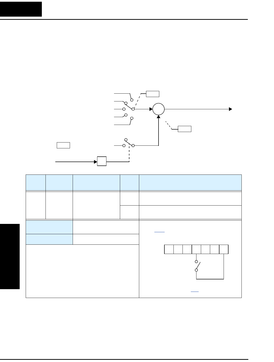
Using Intelligent Input Terminals
Operations
and Monitoring
4–32
ADD Frequency Enable
The inverter can add or subtract an offset value to the output frequency setting which is
specified by A001 (will work with any of the five possible sources). The ADD
Frequency is a value you can store in parameter A145. The ADD Frequency is summed
with or subtracted from the output frequency setting only when the [ADD] terminal is
ON. Function A146 selects whether to add or subtract. By configuring an intelligent
input as the [ADD] terminal, your application can selectively apply the fixed value in
A145 to offset (positively or negatively) the inverter output frequency in real time.
A001
Function F001 setting
Control terminal
Network variable F001
Calculate function output
Keypad potentiometer
A145
+
∑
+/–
ADD frequency
Frequency source setting
Output frequency setting
[ADD]Intelligent input
A146 ADD direction select
Option
Code
Terminal
Symbol Function Name Input
State Description
50 ADD ADD Frequency
Enable
ON Applies the A145 Add Frequency value to the
output frequency.
OFF Does not apply the Add Frequency. The output
frequency retains its normal value.
Valid for inputs: C001, C002, C003, C004,
C005
Required settings: A001, A145, A146
Notes:
•A001 may specify any source; the Add Frequency
will be added to or subtracted from that value to
yield the output frequency value.
Example (requires input configuration—see
page 3–47):
See I/O specs on page 4–6.
ADD
12345L
PCS
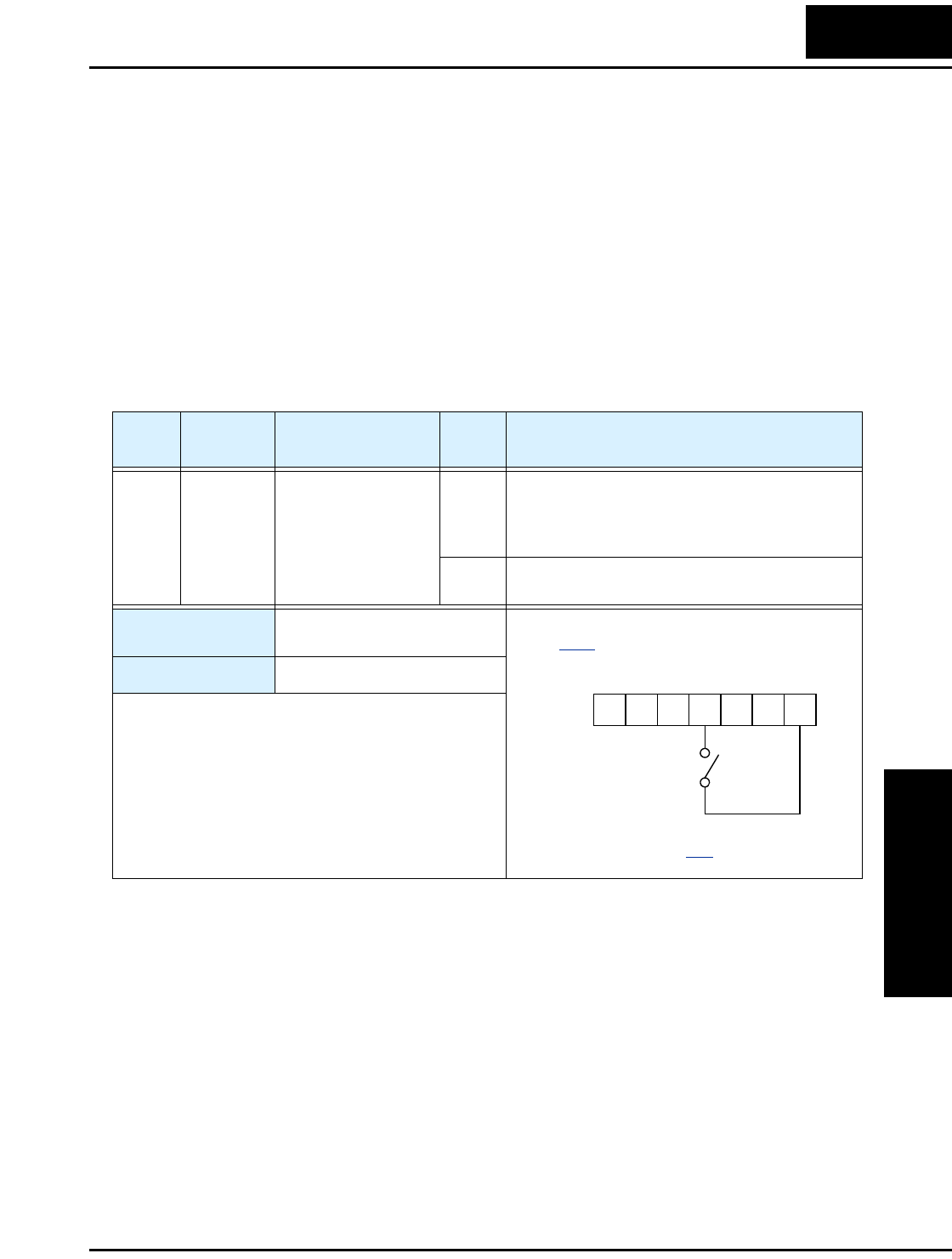
L2002 Inverter
Operations
and Monitoring
4–33
Force Terminal Mode
The purpose of this intelligent input is to allow a device to force the inverter to allow
control of the following two parameters via the control terminals:
• A001 - Frequency source setting (01 = control terminals [FW] and [RV])
• A002 - Run command source setting (01 = control terminals [O] or [OI])
Some applications will require one or both settings above to use a source other than the
terminals. You may prefer to normally use the inverter’s keypad and potentiometer, or to
use the ModBus network for control, for example. However, an external device can turn
ON the [F-TM] input to force the inverter to (temporarily) allow control (frequency
source and Run command) via control terminals. When the [F-TM] input is OFF, then
the inverter uses the regular sources specified by A001 and A002 again.
Option
Code
Terminal
Symbol Function Name Input
State Description
51 F-TM Force Terminal
Mode
ON Forces A001=01 (frequency source setting =
control terminal), and
A002=01(Run command source setting = control
terminal)
OFF Inverter applies the user setting for A001 and
A002 normally
Valid for inputs: C001, C002, C003, C004,
C005
Required settings: A001, A002
Notes:
•When changing the [F-TM] state during Run Mode
(inverter is driving the motor), the inverter will stop
the motor before the new [F-TM] state takes effect.
Example (requires input configuration—see
page 3–47):
See I/O specs on page 4–6.
F-TM
12345L
PCS
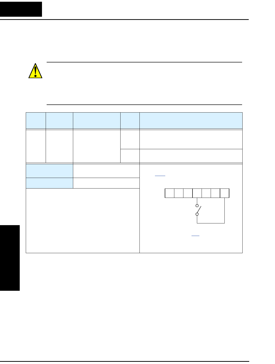
Using Intelligent Input Terminals
Operations
and Monitoring
4–34
Quick Start Enable
When the [RDY] input is ON, the inverter is always in Run Mode, even when the motor
rotation has stopped. The pupose of the quick start feature is to improve (decrease) the
startup time of the motor in response to a Run Command.
CAUTION: While the [RDY] input is ON, voltage will be present on the output of the
inverter, even when the motor is still. In this case:
• Do not touch the motor output terminals. Otherwise, there is the danger of electric
shock.
• Do not short the motor leads together or to ground. Otherwise, you may damage the
inverter output circuit
Option
Code
Terminal
Symbol Function Name Input
State Description
52 RDY Quick Start Enable ON Inverter output is always ON (even when motor
rotation has stopped) to improve motor startup
time.
OFF Inverter output turns OFF normally in Stop
Mode.
Valid for inputs: C001, C002, C003, C004,
C005
Required settings: B151=00
Notes:
•When the [RDY] input is ON, the inverter output is
energized the Run LED is always ON.
•When the [RDY] input is ON, you may edit only
parameters that can be edited in Run Mode. To edit
any parameter, turn OFF the [RDY] input and the
Run Command to put the inverter in Stop Mode.
•Function B151 can also enable the Quick Start
function (B151=01). In that case, the [RDY] input
should not be used, because the inverter ignores it.
Example (requires input configuration—see
page 3–47):
See I/O specs on page 4–6.
RDY
12345L
PCS
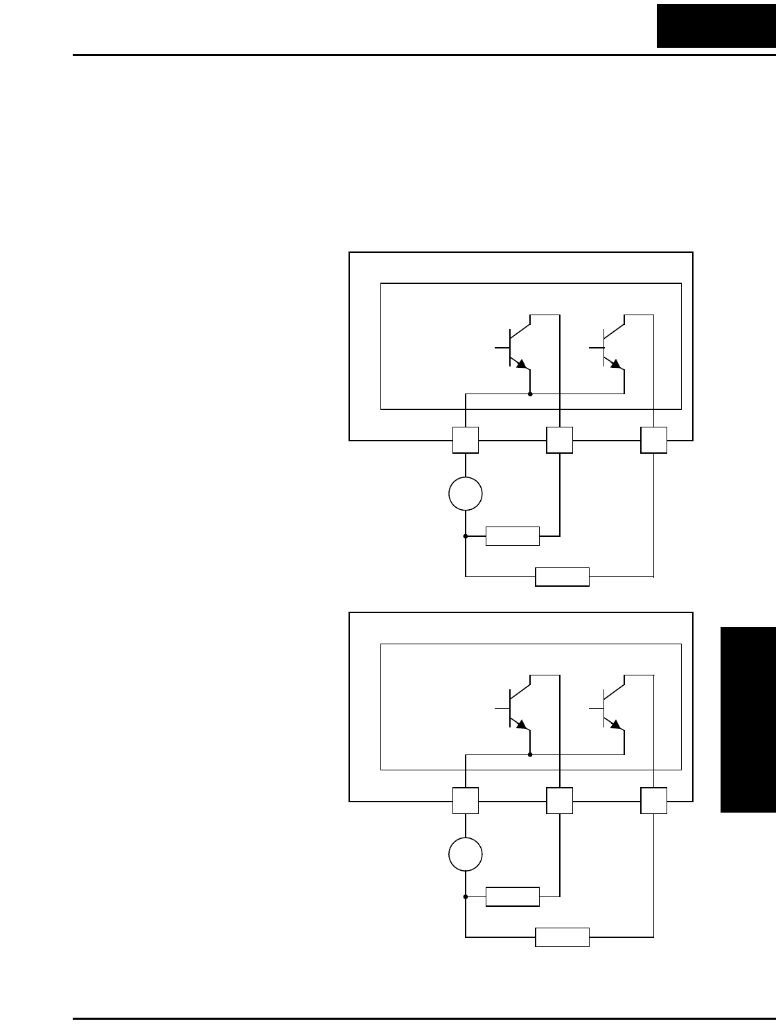
L2002 Inverter
Operations
and Monitoring
4–35
Using Intelligent Output Terminals
The intelligent output terminals are programmable in a similar way to the intelligent
input terminals. The inverter has several output functions that you can assign individu-
ally to three physical logic outputs. Two of the outputs are open-collector transistors, and
the third output is the alarm relay (form C – normally open and normally closed
contacts). The relay is assigned the alarm function by default, but you can assign it to
any of the functions that the open-collector outputs use.
Sinking Outputs,
Open Collector
Sinking Outputs,
Open Collector with
External Relays
L2002 Inverter
12 11
CM2
Open collector outputs
Load
Load
–
+
Logic output
common
The open-collector transistor
outputs can handle up to
50mA each. We highly recom-
mend that you use an external
power source as shown. It
must be capable of providing
at least 100mA to drive both
outputs at full load. To drive
loads that require more than
50mA, use external relay
circuits as shown to the right.
L2002 Inverter
12 11
CM2
Open collector outputs
Load
Load
–
+
Logic output
common
If you need output current
greater than 50mA, use the
inverter output to drive a small
relay. Be sure to use a diode
across the coil of the relay as
shown (reverse-biased) in
order to suppress the turn-off
spike, or use a solid-state
relay.

Using Intelligent Output Terminals
Operations
and Monitoring
4–36
Internal Relay Output
The inverter has an internal relay output with
normally open and normally closed contacts (Type
1 form C). The output signal that controls the relay
is configurable; the Alarm Signal is the default
setting. Thus, the terminals are labeled [AL0],
[AL1], [AL2], as shown to the right. However, you
can assign any one of the nine intelligent outputs to
the relay. For wiring purposes, the general terminal
function are:
• [AL0] – Common contact
• [AL1] – Normally open contact
• [AL2] – Normally closed contact
The relay itself can be configured as “normally open or closed.” Parameter C036, Alarm
Relay Active State, is the setting. This setting determines whether or not the relay coil is
energized when its output signal is OFF:
• C036=00 – “Normally open” (relay coil is de-energized when output signal is OFF)
• C036=01 – “Normally closed” (relay coil is energized when the output signal is OFF)
Since the relay already has normally open [AL1]
and normally closed [AL2] contacts, the purpose of
the ability to invert the relay coil’s active state may
not be obvious. It allows you to determine whether
or not an inverter power loss causes the relay to
change state. The default relay configuration is the
Alarm Signal (C026=05), as shown to the right.
And, C036=01 sets the relay to “normally closed”
(relay coil normally energized). The reason for this
is that a typical system design will require an
inverter power loss to assert an alarm signal to
external devices.
The relay can be used for other intelligent output
signals, such as the Run Signal (set C026=00). For
these remaining output signal types, the relay coil
typically must NOT change state upon inverter
power loss (set C036=00). The figure to the right
shows the relay settings for the Run Signal output.
If you assign the relay an output signal other than
the Alarm Signal, the inverter can still have an
Alarm Signal output. In this case, you can assign it
to either terminal [11] or [12], providing an open
collector output.
AL0 AL2AL1
Inverter logic
circuit board
AL0 AL2AL1
Inverter logic
circuit board AL
C026=05
C036=01
Relay shown with inverter
power ON, Alarm Signal OFF
AL0 AL2AL1
Inverter logic
circuit board RUN
C026=00
C036=00
Relay shown with inverter
power ON, Run Signal OFF
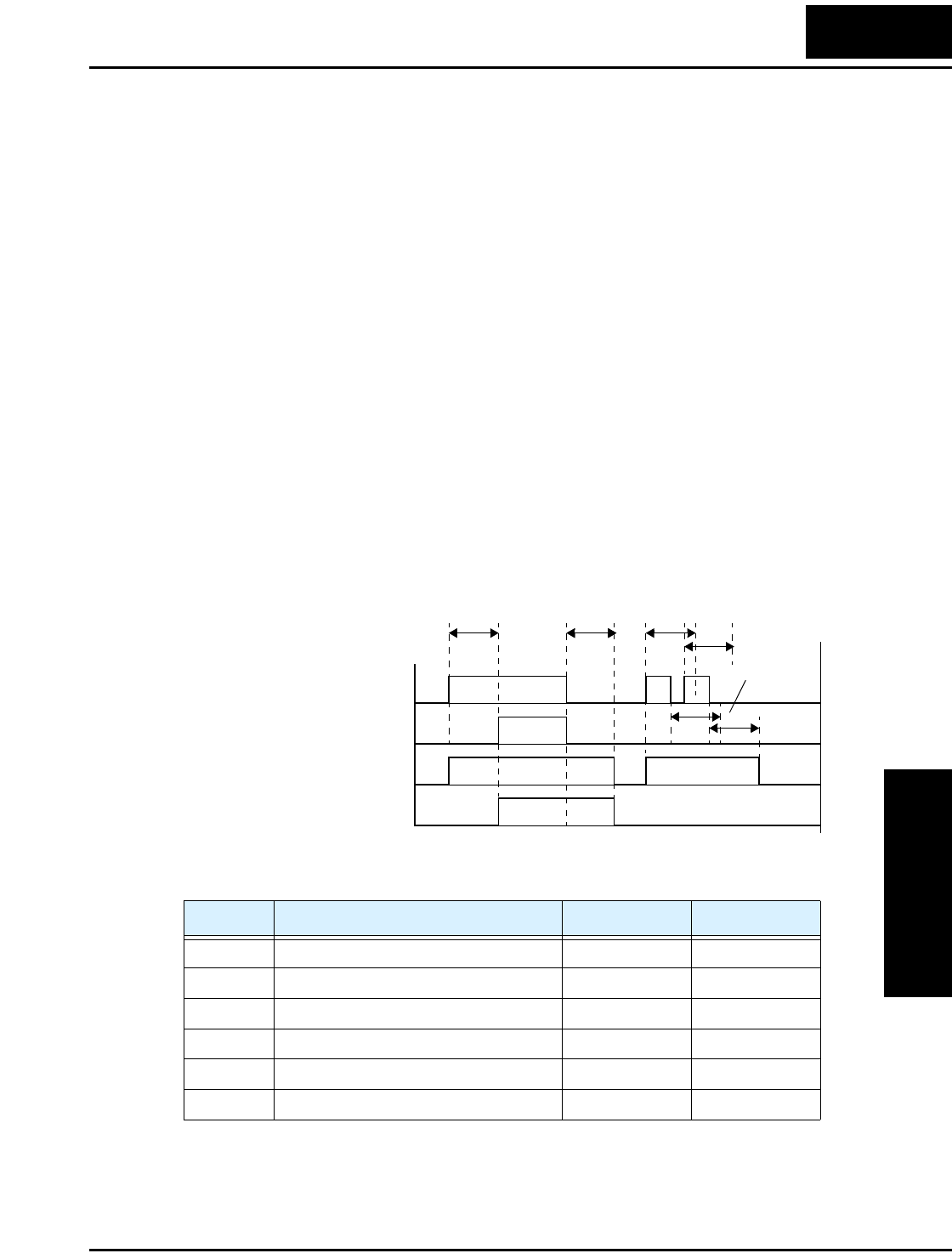
L2002 Inverter
Operations
and Monitoring
4–37
Output Signal ON/OFF Delay Function
Intelligent outputs including terminals [11], [12], and the output relay, have configurable
signal transition delays. Each output can delay either the OFF-to-ON or ON-to-OFF
transitions, or both. Signal transition delays are variable from 0.1 to 100.0 seconds. This
feature is useful in applications that must tailor inverter output signals to meet timing
requirements of certain external devices.
The timing diagram below shows a sample output signal (top line) and the results of
various ON/OFF delay configurations.
•Original signal - This example signal waveform consists of three separate pulses
named “A,” “B,” and “C.”
•...with ON delay - Pulse A is delayed by the duration of the ON delay time. Pulses B
and C do not appear at the output, because they are shorter than the ON delay.
•...with OFF delay - Pulse A is lengthened by the amount of the OFF delay time. The
separation between pulses B and C does not appear at the output, because it is shorter
than the OFF delay time.
•...with ON/OFF delays - Pulse A is delayed on both leading and trailing edges by the
amounts of the ON and OFF delay times, respectively. Pulses B and C do not appear at
the output, because they are shorter than the ON delay time.
To configure ON and OFF delays, use the following table to set the desired delay times.
Use of the ON/OFF signal delay functions are optional. Note that any of the
intelligent output assignments in this section can be combined with ON/OFF signal
timing delay configurations.
Func. Description Range Default
C144 Terminal [11] ON delay 0.0 to 100.0 sec. 0.0
C145 Terminal [11] OFF delay 0.0 to 100.0 sec. 0.0
C146 Terminal [12] ON delay 0.0 to 100.0 sec. 0.0
C147 Terminal [12] OFF delay 0.0 to 100.0 sec. 0.0
C148 Output relay ON delay 0.0 to 100.0 sec. 0.0
C149 Output relay OFF delay 0.0 to 100.0 sec. 0.0
original (no delays)
1
0
t
1
0
1
0
...with ON delay
1
0
Output Signals:
...with OFF delay
...with ON/OFF delays
ABC
ON
delay
OFF
delay
ON
delays
OFF
delays
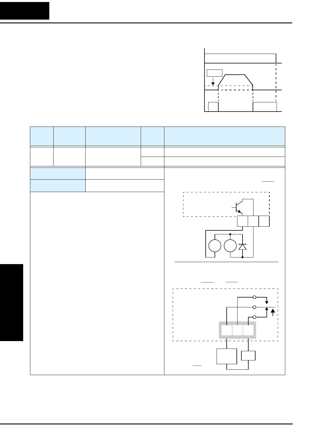
Using Intelligent Output Terminals
Operations
and Monitoring
4–38
Run Signal
When the [RUN] signal is selected as an
intelligent output terminal, the inverter
outputs a signal on that terminal when it is in
Run Mode. The output logic is active low, and
is the open collector type (switch to ground).
[FW],
[RV]
Output
freq.
Run
Signal
start freq.
t
ON
1
0
1
0
B082
Option
Code
Terminal
Symbol Function Name Output
State Description
00 RUN Run Signal ON when inverter is in Run Mode
OFF when inverter is in Stop Mode
Valid for outputs: 11, 12, AL0 – AL2
Required settings: (none)
Notes:
•The inverter outputs the [RUN] signal whenever the
inverter output exceeds the start frequency specified
by parameter B082. The start frequency is the initial
inverter output frequency when it turns ON.
•The example circuit for terminal [12] drives a relay
coil. Note the use of a diode to prevent the negative-
going turn-off spike generated by the coil from
damaging the inverter’s output transistor.
RY
+
–
Example for terminals [11] and [12] (default
output configuration shown—see page 3–54):
Inverter output
terminal circuit
RUN
Example for terminals [AL0], [AL1], [AL2]
(requires output configuration—
see pages 4–36 and 3–54):
AL0 AL2AL1
Inverter logic
circuit board
See I/O specs
on page 4–6.
RUN
Load
Power
supply
12 11
CM2

L2002 Inverter
Operations
and Monitoring
4–39
Frequency Arrival Signals
The Frequency Arrival group of outputs help coordinate external systems with the
current velocity profile of the inverter. As the name implies, output [FA1] turns ON
when the output frequency arrives at the standard set frequency (parameter F001).
Output [FA2] relies on programmable accel/ decel thresholds for increased flexibility.
For example, you can have an output turn ON at one frequency during acceleration, and
have it turn OFF at a different frequency during deceleration. All transitions have hyster-
esis to avoid output chatter if the output frequency is near one of the thresholds.
Option
Code
Terminal
Symbol Function Name Output
State Description
01 FA1 Frequency Arrival
Type 1 – Constant
Speed
ON when output to motor is at the set frequency
OFF when output to motor is OFF, or in any accelera-
tion or deceleration ramp
02 FA2 Frequency Arrival
Type 2 – Over-
frequency
ON when output to motor is at or above the FA2
threshold (C042) during accel
OFF when output to motor is below the FA2 threshold
(C043) during decel
Valid for outputs: 11, 12, AL0 – AL2
Required settings: (none)
Notes:
•For most applications you will need to use only one
type of frequency arrival outputs (see examples).
However, it is possible assign both output terminals
to output functions [FA1] and [FA2].
•For each frequency arrival threshold, the output
anticipates the threshold (turns ON early) by 1.5Hz.
•The output turns OFF as the output frequency
moves away from the threshold, delayed by 0.5Hz.
•The delay time of the output signal is 60 ms
(nominal).
•The example circuit for terminal [12] drives a relay
coil. Note the use of a diode to prevent the negative-
going turn-off spike generated by the coil from
damaging the inverter’s output transistor.
Example (default output configuration
shown—see page 3–54):
Inverter output
terminal circuit
RY
+
–
FA1
Example for terminals [AL0], [AL1], [AL2]
(requires output configuration—
see pages 4–36 and 3–54):
AL0 AL2AL1
Inverter logic
circuit board
See I/O specs
on page 4–6.
FA1
Load
Power
supply
12 11
CM2

Using Intelligent Output Terminals
Operations
and Monitoring
4–40
Frequency arrival output [FA1] uses the
standard output frequency (parameter
F001) as the threshold for switching. In
the figure to the right, Frequency Arrival
[FA1] turns ON when the output
frequency gets within 0.5 Hz below or
1.5 Hz above the target constant
frequency. This provides hysteresis that
prevents output chatter near the threshold
value.The hysteresis effect causes the
output to turn ON slightly early as the
speed approaches the threshold. Then the
turn-OFF point is slightly delayed. The
timing is further modified by a small
60 ms delay. Note the active low nature of
the signal, due to the open collector output.
Frequency arrival output [FA2] works the
same way; it just uses two separate
thresholds as shown in the figure to the
right. These provide for separate acceler-
ation and deceleration thresholds to
provide more flexibility than for [FA1].
[FA2] uses C042 during acceleration for
the ON threshold, and C0043 during
deceleration for the OFF threshold. This
signal also is active low and has a 60 ms
delay after the frequency thresholds are
crossed. Having different accel and decel
thresholds provides an asymmetrical
output function. However, you can use
equal ON and OFF thresholds, if desired.
FA1
signal
Output
freq.
60 ms 60 ms
ON ON
t
0.5 Hz
0.5 Hz 1.5 Hz
1.5 Hz
0
t
F001 F001
FA2
signal
Output
freq.
t
ON
0.5 Hz 1.5 Hz
60 ms
accel.
decel.
Thresholds
60 ms
0
C043
C042
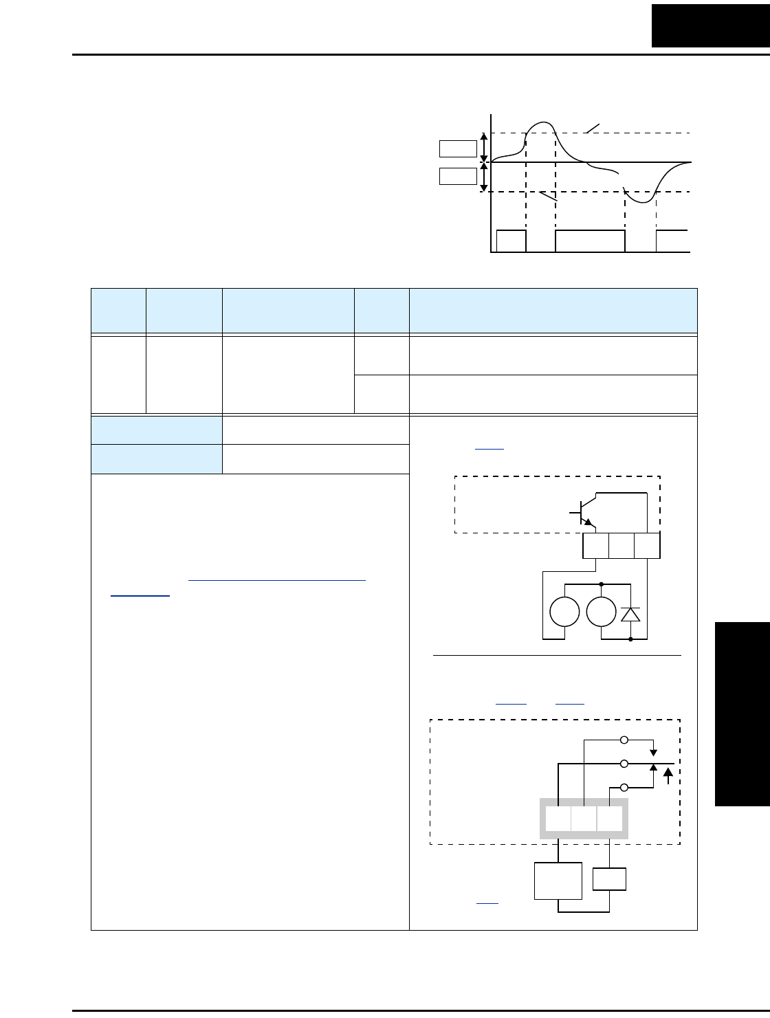
L2002 Inverter
Operations
and Monitoring
4–41
Overload Advance Notice Signal
When the output current exceeds a preset
value, the [OL] terminal signal turns ON.
The parameter C041 sets the overload
threshold. The overload detection circuit
operates during powered motor opera-
tion and during regenerative braking. The
output circuits use open-collector
transistors, and are active low.
[OL]
Signal
1
0ON
t
ON
Current
threshold
regeneration
power running
threshold
C041
C041
Option
Code
Terminal
Symbol Function Name Output
State Description
03 OL Overload Advance
Notice Signal
ON when output current is more than the set thresh-
old for the overload signal
OFF when output current is less than the set threshold
for the overload signal
Valid for outputs: 11, 12, AL0 – AL2
Required settings: C041
Notes:
•The default value is 100%. To change the level
from the default, set C041 (overload level).
•The accuracy of this function is the same as the
function of the output current monitor on the [FM]
terminal (see “Analog Output Operation” on
page 4–55).
•The example circuit for terminal [12] drives a relay
coil. Note the use of a diode to prevent the negative-
going turn-off spike generated by the coil from
damaging the inverter’s output transistor.
RY
+
–
Example (requires output configuration—
see page 3–54):
Inverter output
terminal circuit
OL
Example for terminals [AL0], [AL1], [AL2]
(requires output configuration—
see pages 4–36 and 3–54):
AL0 AL2AL1
Inverter logic
circuit board
See I/O specs
on page 4–6.
OL
Load
Power
supply
12 11
CM2
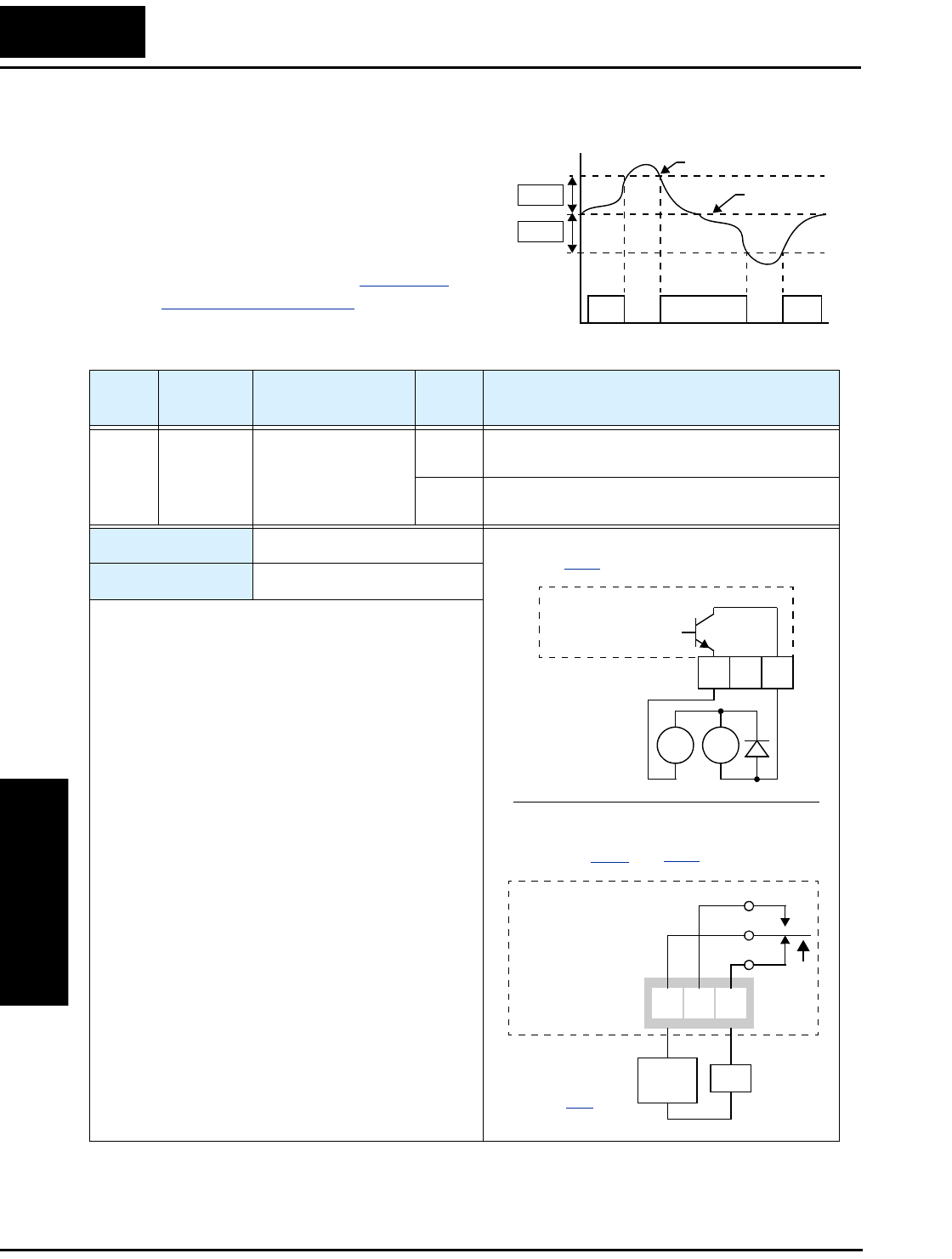
Using Intelligent Output Terminals
Operations
and Monitoring
4–42
Output Deviation for PID Control
The PID loop error is defined as the
magnitude (absolute value) of the differ-
ence between the Setpoint (target value)
and the Process Variable (actual value).
When the error magnitude exceeds the
preset value for C044, the [OD] terminal
signal turns ON. Refer to “PID Loop
Operation” on page 4–56.[OD]
Signal
SP, PV
1
0
t
ONON
Setpoint
Process variable
C044
C044
Option
Code
Terminal
Symbol Function Name Output
State Description
04 OD Output Deviation for
PID Control
ON when PID error is more than the set threshold for
the deviation signal
OFF when PID error is less than the set threshold for
the deviation signal
Valid for outputs: 11, 12, AL0 – AL2
Required settings: C044
Notes:
•The default difference value is set to 3%. To change
this value, change parameter C044 (deviation
level).
•The example circuit for terminal [12] drives a relay
coil. Note the use of a diode to prevent the negative-
going turn-off spike generated by the coil from
damaging the inverter’s output transistor.
RY
+
–
Example (requires output configuration—
see page 3–54):
Inverter output
terminal circuit
OD
Example for terminals [AL0], [AL1], [AL2]
(requires output configuration—
see pages 4–36 and 3–54):
AL0 AL2AL1
Inverter logic
circuit board
See I/O specs
on page 4–6.
OD
Load
Power
supply
12 11
CM2
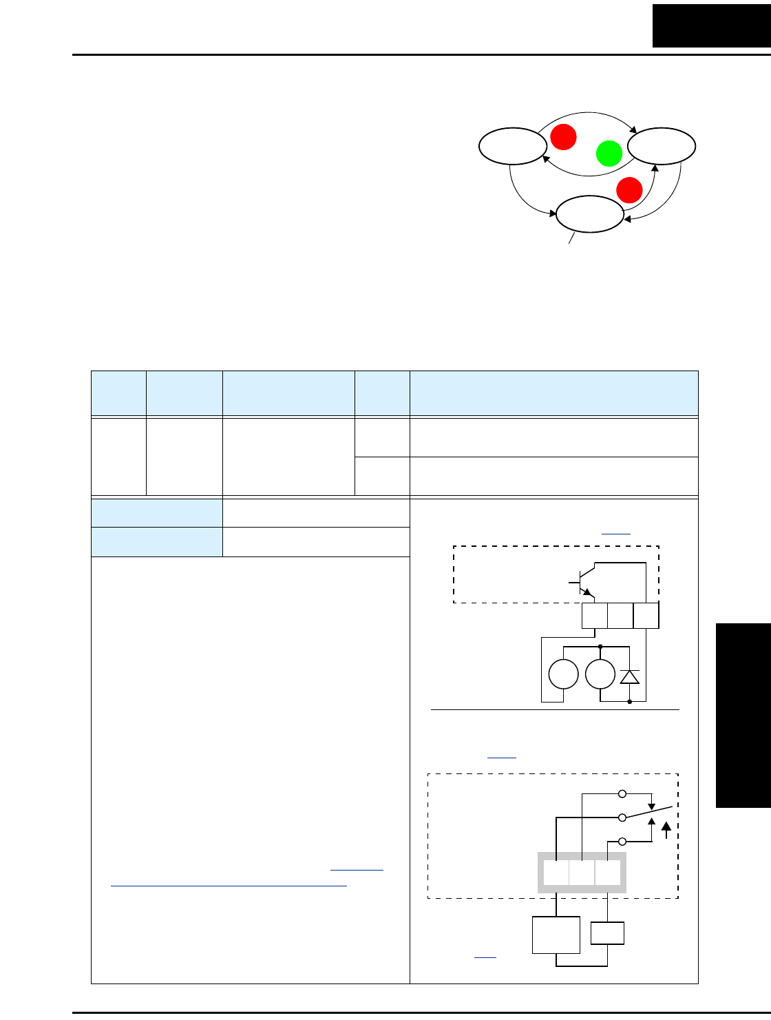
L2002 Inverter
Operations
and Monitoring
4–43
Alarm Signal
The inverter alarm signal is active when a fault has
occurred and it is in the Trip Mode (refer to the
diagram at right). When the fault is cleared the
alarm signal becomes inactive.
We must make a distinction between the alarm
signal AL and the alarm relay contacts [AL0],
[AL1] and [AL2]. The signal AL is a logic
function, which you can assign to the open collec-
tor output terminals [11] or [12] or the relay
outputs. The most common (and default) use of the relay is for AL, thus the labeling of
its terminals. Use an open collector output (terminal [11] or [12]) for a low-current logic
signal interface or to energize a small relay (50 mA maximum). Use the relay output to
interface to higher voltage and current devices (10 mA minimum).
Run Stop
Trip
Fault
Fault
Alarm signal active
STOP
RESET
STOP
RESET
RUN
Option
Code
Terminal
Symbol Function Name Output
State Description
05 AL Alarm Signal ON when an alarm signal has occurred and has not
been cleared
OFF when no alarm has occurred since the last
clearing of alarm(s)
Valid for outputs: 11, 12, AL0 – AL2
Required settings: C026, C036
Notes:
•By default, the relay is configured as normally
closed (C036=01). Refer to the next page for an
explanation.
•In the default relay configuration, an inverter power
loss turns ON the alarm output. the alarm signal
remains ON as long as the external control circuit
has power.
•When the relay output is set to normally closed, a
time delay of less than 2 seconds occurs after
powerup before the contact is closed.
•Terminals [11] and [12] are open collector outputs,
so the electric specifications of [AL] are different
from the contact output terminals [AL0], [AL1],
[AL2].
•This signal output has the delay time (300 ms
nominal) from the fault alarm output.
•The relay contact specifications are in “Control
Logic Signal Specifications” on page 4–6. The
contact diagrams for different conditions are on the
next page.
RY
+
–
Example for terminals [AL0], [AL1], [AL2]
(default output configuration shown—
see page 3–54):
Relay position
shown is for
normal opera-
tion (no alarm).
Example for terminal [11] or [12] (requires
output configuration—see page 3–54):
AL0 AL2AL1
Inverter logic
circuit board
Inverter output
terminal circuit
See I/O specs
on page 4–6.
AL
AL
Load
Power
supply
12 11
CM2
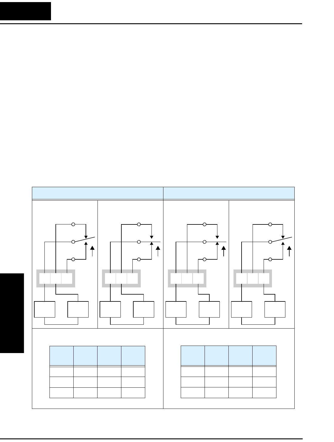
Using Intelligent Output Terminals
Operations
and Monitoring
4–44
The alarm relay output can be configured in two main ways:
•Trip/Power Loss Alarm – The alarm relay is configured as normally closed
(C036=1) by default, shown below (left). An external alarm circuit that detects broken
wiring also as an alarm connects to [AL0] and [AL1]. After powerup and short delay
(< 2 seconds), the relay energizes and the alarm circuit is OFF. Then, either an inverter
trip event or an inverter power loss will de-energize the relay and open the alarm
circuit.
•Trip Alarm – Alternatively, you can configure the relay as normally open (C036=0),
shown below (right). An external alarm circuit that detects broken wiring also as an
alarm connects to [AL0] and [AL2]. After powerup, the relay energizes only when an
inverter trip event occurs, opening the alarm circuit. However, in this configuration, an
inverter power loss does not open the alarm circuit.
Be sure to use the relay configuration that is appropriate for your system design. Note
that the external circuits shown assume that a closed circuit = no alarm condition (so that
a broken wire also causes an alarm). However, some systems may require a closed
circuit = alarm condition. In that case, then use the opposite terminal [AL1] or [AL2]
from the ones shown.
N.C. contacts (C036=01) N.O. contact (C036=00)
During normal operation When an alarm occurs
or when power is OFF
During normal operation
or when power is OFF
When an alarm occurs
AL0 AL2AL1
Power
supply
Alarm
device
AL0 AL2AL1
Power
supply
Alarm
device
AL0 AL2AL1
Power
supply
Alarm
device
AL0 AL2AL1
Power
supply
Alarm
device
Power Run
Mode
AL0–
AL1
AL0–
AL2
ON Normal Closed Open
ON Trip Open Closed
OFF — Open Closed
Power Run
Mode
AL0–
AL1
AL0–
AL2
ON Normal Open Closed
ON Trip Closed Open
OFF — Open Closed
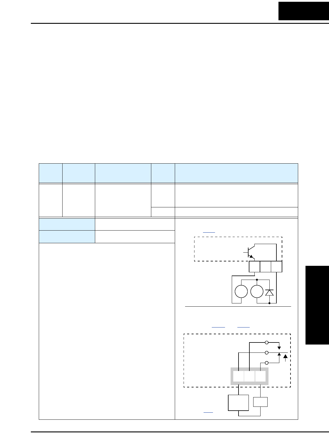
L2002 Inverter
Operations
and Monitoring
4–45
Analog Input Disconnect Detect
This feature is useful when the inverter receives a speed reference from an external
device. Upon input signal loss at either the [O] or [OI] terminal, the inverter normally
just decelerates the motor to a stop. However, the inverter can use the intelligent output
terminal [Dc] to signal other machinery that a signal loss has occurred.
Voltage signal loss at [O] terminal - Parameter B082 is the Start Frequency Adjust-
ment. It sets the beginning (minimum) output frequency when the speed reference
source is greater than zero. If the analog input at terminal [O] is less than the Start
Frequency, the inverter turns ON the [Dc] output to indicate a signal loss condition.
Current signal loss at [OI] terminal - The [OI] terminal accepts a 4mA to 20mA
signal, with 4mA representing the beginning of the input range. If the input current falls
below 4mA, the inverter applies a threshold to detect signal loss.
Note that a signal loss is not an inverter trip event. When the analog input value is again
above the B082 value, the [Dc] output turns OFF. There is no error condition to clear.
Option
Code
Terminal
Symbol Function Name Output
State Description
06 Dc Analog Input
Disconnect Detect
ON when the [O] input value < B082 Start
Frequency Adjustment (signal loss detected), or
when the [OI input current is less than 4mA
OFF when no signal loss is detected
Valid for outputs: 11, 12, AL0 – AL2
Required settings: A001=01, B082
Notes:
•The [Dc] output can indicate an analog signal
disconnect when the inverter is in Stop Mode, as
well as Run Mode.
•The example circuit for terminal [12] drives a relay
coil. Note the use of a diode to prevent the negative-
going turn-off spike generated by the coil from
damaging the inverter’s output transistor.
RY
+
–
Example (requires output configuration—
see page 3–54):
Inverter output
terminal circuit
Dc
Example for terminals [AL0], [AL1], [AL2]
(requires output configuration—
see pages 4–36 and 3–54):
AL0 AL2AL1
Inverter logic
circuit board
See I/O specs
on page 4–6.
Dc
Load
Power
supply
12 11
CM2
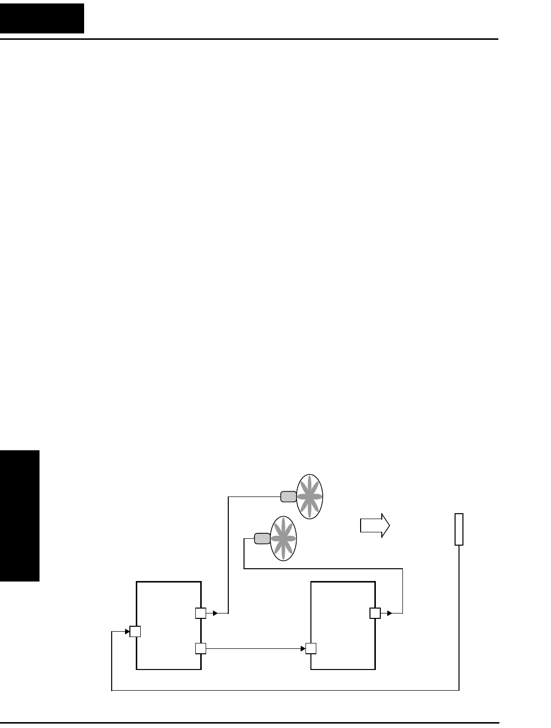
Using Intelligent Output Terminals
Operations
and Monitoring
4–46
PID Second Stage Output
The inverter has a built-in PID loop feature for two-stage control, useful for certain
applications such as building ventilation or heating and cooling (HVAC). In an ideal
control environment, a single PID loop controller (stage) would be adequate. However,
in certain conditions, the maximum output energy from the first stage is not enough to
maintain the Process Variable (PV) at or near the Setpoint (SP). And, the output of the
first stage is in saturation. A simple solution is to add a second stage, which puts an
additional and constant amount of energy into the system under control. When sized
properly, the boost from the second stage brings the PV toward the desired range,
allowing the first stage PID control to return to its linear range of operation.
The two-stage method of control has some advantages for particular applications.
• The second stage is only ON in adverse conditions, so there is an energy savings
during normal conditions.
• Since the second stage is simple ON/OFF control, it is less expensive to add than just
duplicating the first stage.
• At powerup, the boost provided by the second stage helps the process variable reach
the desired setpoint sooner than it would if the first stage acted alone.
• Even though the second stage is simple ON/OFF control, when it is an inverter you
can still adjust the output frequency to vary the boost it provides.
Refer to the example diagram below. Its two stages of control are defined as follows:
• Stage 1 - Inverter #1 operating in PID loop mode, with motor driving a fan
• Stage 2 - Inverter #2 operating as an ON/OFF controller, with motor driving a fan
Stage #1 provides the ventilation needs in a building most of the time. On some days,
there is a change in the building’s air volume because large warehouse doors are open. In
that situation, Stage #1 alone cannot maintain the desired air flow (PV sags under SP).
Inverter #1 senses the low PV and its PID Second Stage Output at [FBV] terminal turns
ON. This gives a Run FWD command to Inverter #2 to provide the additional air flow.
Sensor
Inverter#2Inverter #1
[FBV] [FW]
[O or [OI]] PID Second
Stage Output
PV
Process Variable
[U, V, W] [U, V, W]
Fan#1
Fan#2
Air flow
Stage #1 Stage #2
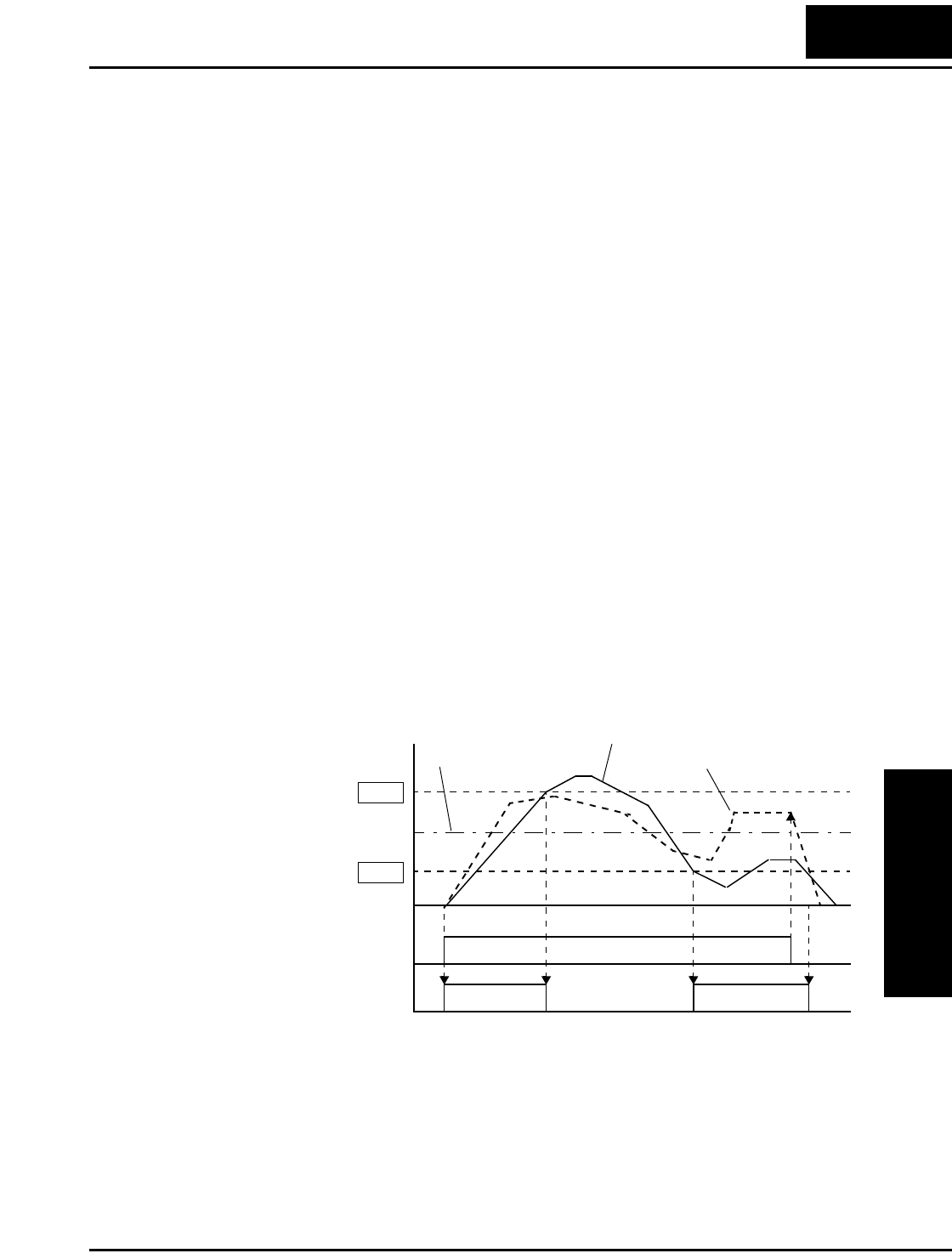
L2002 Inverter
Operations
and Monitoring
4–47
To use the PID Second Stage Output feature, you will need to choose upper and lower
limits for the PV, via C053 and C052 respectively. As the timing diagram below shows,
these are the thresholds Stage #1 inverter uses to turn ON or OFF Stage #2 inverter via
the [FBV] output. The vertical axis units are percent (%) for the PID setpoint, and for the
upper and lower limits. The output frequency, in Hz, is superimposed onto the same
diagram.
When the system control begins, the following events occur (in sequence in the timing
diagram):
1. Stage #1 inverter turns ON via the [FW] Run command.
2. Stage #1 inverter turns ON the [FBV] output, because the PV is below the PV low
limit C053. So, Stage #2 is assisting in loop error correction from the beginning.
3. The PV rises and eventually exceeds the PV high limit C052. Stage #1 inverter then
turns OFF the [FBV] output to Stage #2, since the boost is no longer needed.
4. When the PV begins decreasing, only Stage #1 is operating, and it is in the linear
control range. This region is where a properly configured system will operate most
often.
5. The PV continues to decrease until it crosses under the PV low limit (apparent
external process disturbance). Stage #1 inverter turns ON the [FBV] output, and Stage
#2 inverter is assisting again.
6. After the PV rises above the PV low limit, the [FW] Run command to Stage #1
inverter turns OFF (as in a system shutdown).
7. Stage #1 inverter enters Stop Mode and automatically turns OFF the [FBV] output,
which causes Stage #2 inverter to also stop.
The terminal [FBV] configuration table is on the following page.
%/Hz
[FBV] to Stage #2 [FW]
Stage #1 [FW] 1
0
t
1
0
C053
C052
PV high limit
PV low limit
PID feedback (PV)
Output frequency
Events: 1,2 3 4 5 6 7
PID setpoint (SP)
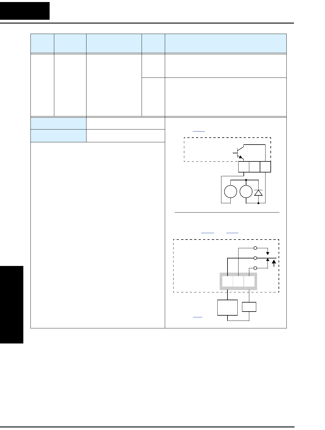
Using Intelligent Output Terminals
Operations
and Monitoring
4–48
Option
Code
Terminal
Symbol Function Name Output
State Description
07 FBV Feedback Value
Check
ON •Transitions to ON when the inverter is in RUN
Mode and the PID Process Variable (PV) is
less than the Feedback Low Limit (C053)
OFF •Transitions to OFF when the PID Feedback
Value (PV) exceeds the PID High Limit
(C052)
•Transitions to OFF when the inverter goes
from Run Mode to Stop Mode
Valid for outputs: 11, 12, AL0 – AL2
Required settings: A076, C052, C053
Notes:
•The [FBV] is designed for implementing two-stage
control. The PV high limit and PV low limit param-
eters, C052 and C053, do not function as process
alarm thresholds. Terminal [FBV] does not provide
a PID alarm function.
•The example circuit for terminal [12] drives a relay
coil. Note the use of a diode to prevent the negative-
going turn-off spike generated by the coil from
damaging the inverter’s output transistor.
RY
+
–
Example (requires output configuration—
see page 3–54):
Inverter output
terminal circuit
FBV
Example for terminals [AL0], [AL1], [AL2]
(requires output configuration—
see pages 4–36 and 3–54):
AL0 AL2AL1
Inverter logic
circuit board
See I/O specs
on page 4–6.
FBV
Load
Power
supply
12 11
CM2
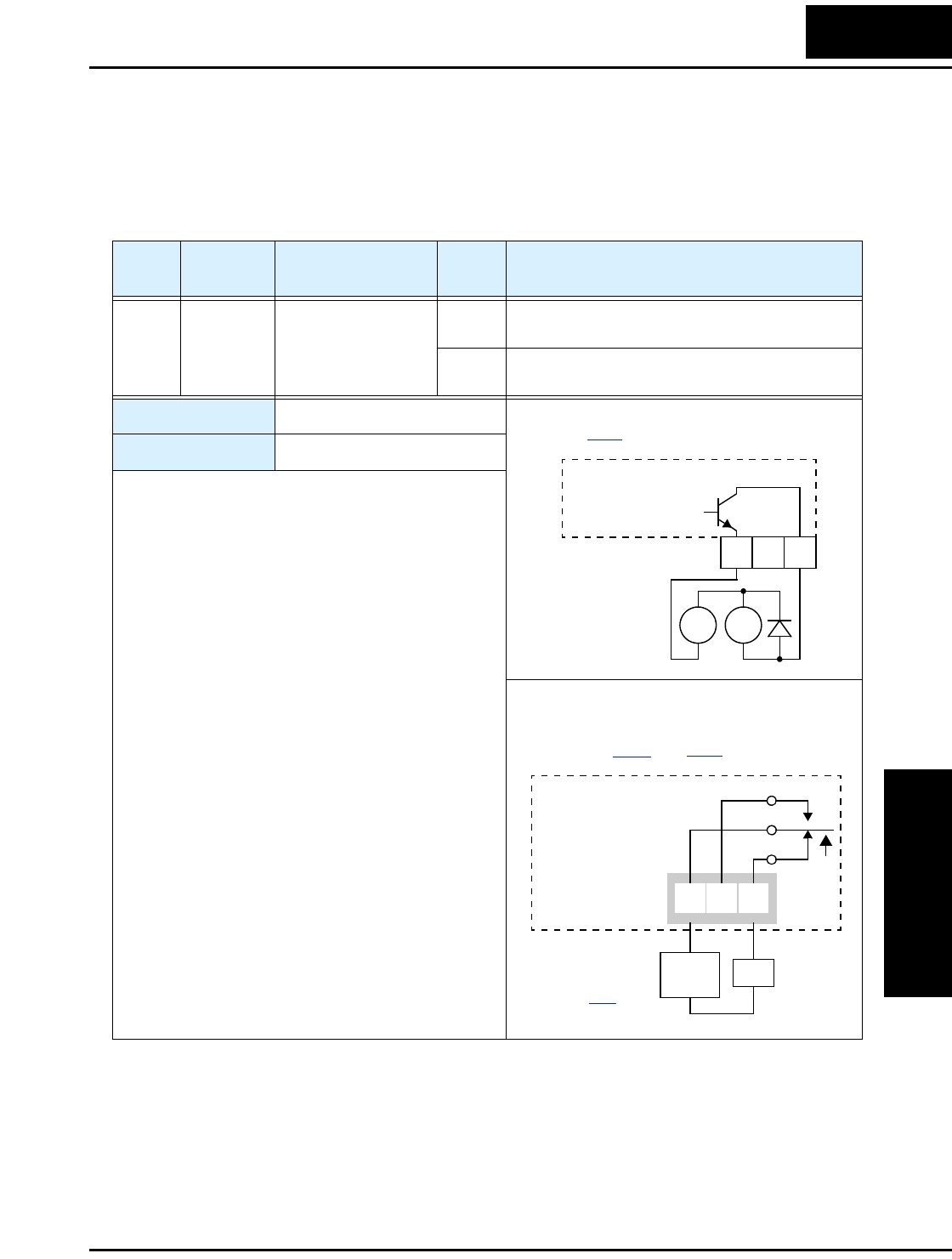
L2002 Inverter
Operations
and Monitoring
4–49
Network Detection Signal
The Network Detection Signal output indicates the general status of network communi-
cations. The inverter has a programmable watchdog timer to monitor network activity.
Parameter C077 sets the time-out period. If communications stop or pause longer than
the specified time-out period, the Ndc output turns ON.
Additionally, the inverter can respond to a communications time-out in various ways.
Refer to the following diagram (top of next page). You configure the desired response
via function C076, Communications Error Select. This selects whether or not you want
the inverter to trip (alarm with error code E60) and whether to stop the motor or just let it
coast. Together, parameters C076 and C077 set the network detection watchdog time-out
and the inverter’s response.
Option
Code
Terminal
Symbol Function Name Output
State Description
08 NDc Network Detection
Signal
ON when the communications watchdog timer
(period specified by C077) has timed out
OFF when the communications watchdog timer is
satisfied by regular communications activity
Valid for outputs: 11, 12, AL0 – AL2
Required settings: C076, C077
Notes:
•To disable the communications watchdog timer, set
C077=00.00 sec.
•If you set Communications Error Select to
“Disable” (C076=02), you still have the option of
using the Network Detection Signal and setting the
watchdog time-out period with C077.
RY
+
–
Example (requires output configuration—
see page 3–54):
Inverter output
terminal circuit
NDc
12 11
CM2
Example for terminals [AL0], [AL1], [AL2]
(requires output configuration—
see pages 4–36 and 3–54):
AL0 AL2AL1
Inverter logic
circuit board
See I/O specs
on page 4–6.
NDc
Load
Power
supply
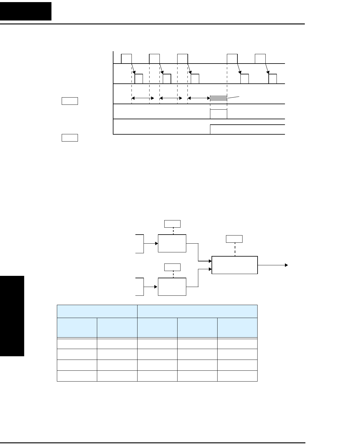
Using Intelligent Output Terminals
Operations
and Monitoring
4–50
Logic Output Function
The Logic Output Function uses the inverter’s built-in logic feature. You can select any
two of the other nine intelligent output options for internal inputs (use C141 and C142).
Then, use C143 to configure the logic function to apply the logical AND, OR, or XOR
(exclusive OR) operator as desired to the two inputs.
[NDc]
t
C076
Master
Watchdog timer
Slave
Time-out
Alarm
=00 or 01
C077 =xx.xx sec.
Input States [LOG] Output State
A Input
(C141 select)
B Input
(C142 select)
AND
(C143=00)
OR
(C143=01)
XOR
(C143=02)
00000
01011
10011
11110
C141
Logic function
AND, OR, XOR
Input A
RUN, FA1, FA2, OL, OD,
AL, Dc, FBV, NDc
Intelligent outputs used
as internal inputs:
C142
Input B
RUN, FA1, FA2, OL, OD,
AL, Dc, FBV, NDc
C143
[LOG]
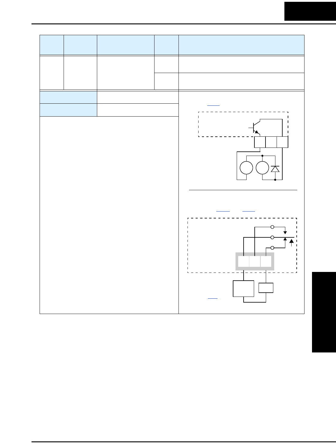
L2002 Inverter
Operations
and Monitoring
4–51
Option
Code
Terminal
Symbol Function Name Output
State Description
09 LOG Logic Output
Function
ON when the Boolean operation specified by C143
has a logical “1” result
OFF when the Boolean operation specified by C143
has a logical “0” result
Valid for outputs: 11, 12, AL0 – AL2
Required settings: C141, C142, C143
Notes:
RY
+
–
Example (requires output configuration—
see page 3–54):
Inverter output
terminal circuit
LOG
Example for terminals [AL0], [AL1], [AL2]
(requires output configuration—
see pages 4–36 and 3–54):
AL0 AL2AL1
Inverter logic
circuit board
See I/O specs
on page 4–6.
LOG
Load
Power
supply
12 11
CM2
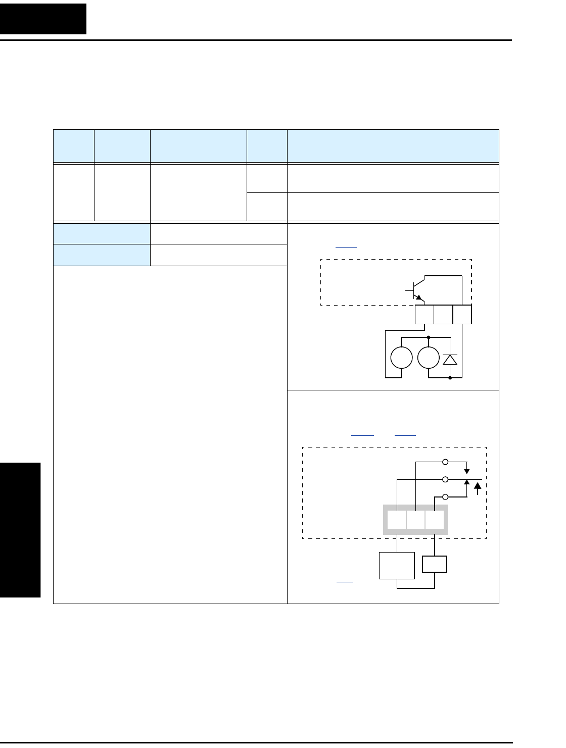
Using Intelligent Output Terminals
Operations
and Monitoring
4–52
Option Card Detection Signal
The expansion card provides a CANopen network interface for the inverter. When the
card is installed, you can configure an intelligent input to indicate the network status.
The watchdog timer value is set by parameter P044.
Option
Code
Terminal
Symbol Function Name Output
State Description
10 ODc Option Card Detec-
tion Signal
ON when the network is detected and operating
normally
OFF when the network is not detected or not operat-
ing normally
Valid for outputs: 11, 12, AL0 – AL2
Required settings: P044
Notes:
RY
+
–
Example (requires output configuration—
see page 3–54):
Inverter output
terminal circuit
ODc
12 11
CM2
Example for terminals [AL0], [AL1], [AL2]
(requires output configuration—
see pages 4–36 and 3–54):
AL0 AL2AL1
Inverter logic
circuit board
See I/O specs
on page 4–6.
ODc
Load
Power
supply
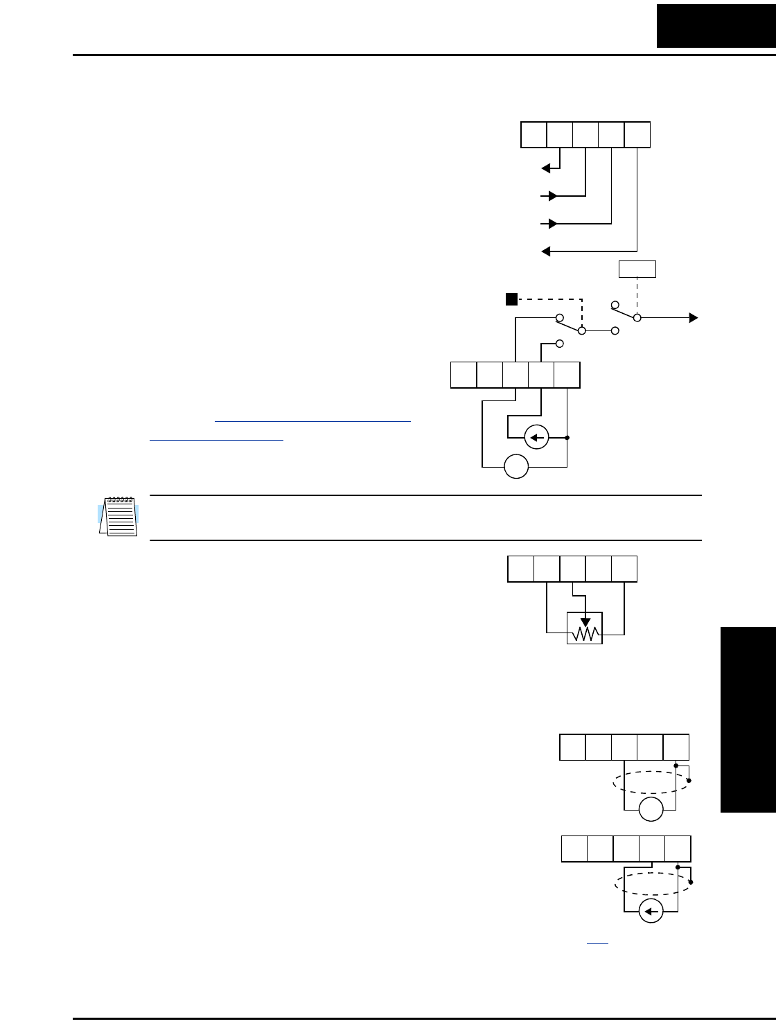
L2002 Inverter
Operations
and Monitoring
4–53
Analog Input Operation
The L2002 inverters provide for analog input
to command the inverter frequency output
value. The analog input terminal group
includes the [L], [OI], [O], and [H] terminals
on the control connector, which provide for
Voltage [O] or Current [OI] input. All analog
input signals must use the analog ground [L].
If you use either the voltage or current analog
input, you must select one of them using the
logic input terminal function [AT] analog
type. If terminal [AT] is OFF, the voltage
input [O] can command the inverter output
frequency. If terminal [AT] is ON, the current
input [OI] can command the inverter output
frequency. The [AT] terminal function is
covered in“Analog Input Current/Voltage
Select” on page 4–23. Remember that you
must also set A001 = 01 to select analog input
as the frequency source.
NOTE: If no logic input terminal is configured for the [AT] function, then inverter sums
the voltage and current input to determine the desired input value.
Using an external potentiometer is a common
way to control the inverter output frequency
(and a good way to learn how to use the
analog inputs). The potentiometer uses the
built-in 10V reference [H] and the analog
ground [L] for excitation, and the voltage
input [O] for the signal. By default, the [AT]
terminal selects the voltage input when it is OFF. Take care to use the proper resistance
for the potentiometer, which is 1 to 2 k Ohms, 2 Watts.
Voltage Input – The voltage input circuit uses
terminals [L] and [O]. Attach the signal
cable’s shield wire only to terminal [L] on the
inverter. Maintain the voltage within specifi-
cations (do not apply negative voltage).
Current Input – The current input circuit
uses terminals [OI] and [L]. The current
comes from a sourcing type transmitter; a
sinking type will not work! This means the
current must flow into terminal [OI], and
terminal [L] is the return back to the transmit-
ter. The input impedance from [OI] to [L] is
250 Ohms. Attach the cable shield wire only to terminal [L] on the inverter.
+V Ref.
A GND
Voltage input
Current input
LH O
OIAM
+ –
4-20 mA, AT=ON
0-10 V, AT=OFF
[AT]
V/I input
select Freq.
setting
LH O
OIAM
A001
1 to 2kΩ, 2W
LH O
OIAM
+ –
4 to 19.6 mA DC,
4 to 20 mA nominal
0 to 9.6 VDC,
0 to 10V nominal
See I/O specs on page 4–6.
LH O
OIAM
LH O
OIAM

Analog Input Operation
Operations
and Monitoring
4–54
The following table shows the available analog input settings. Parameter A005 and the
input terminal [AT] determine the External Frequency Command input terminals that are
available, and how they function. The analog inputs [O] and [OI] use terminal [L] as the
reference (signal return).
Other Analog Input-related topics:
•“Analog Input Settings” on page 3–14
•“Additional Analog Input Settings” on page 3–29
•“Analog Signal Calibration Settings” on page 3–59
•“Analog Input Current/Voltage Select” on page 4–23
•“ADD Frequency Enable” on page 4–32
•“Analog Input Disconnect Detect” on page 4–45
A005 [AT] Input Analog Input Configuration
00 OFF [O]
ON [OI]
01 (ignored) Sum ([O] + [OI])
02 OFF [O]
ON Keypad potentiometer
03 OFF [OI]
ON Keypad potentiometer
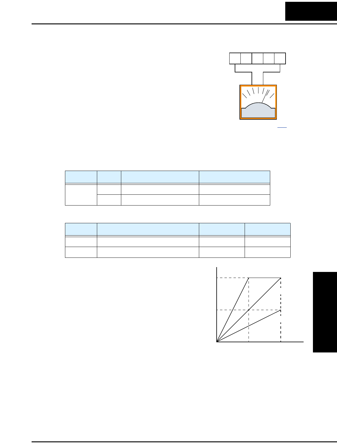
L2002 Inverter
Operations
and Monitoring
4–55
Analog Output Operation
In inverter applications it is useful to monitor
the inverter operation from a remote location or
from the front panel of an inverter enclosure. In
some cases, this requires only a panel-mounted
volt meter. In other cases, a controller such as a
PLC may provide the inverter’s frequency
command, and require inverter feedback data
(such as output frequency or output current) to
confirm actual operation. The analog output
terminal [AM] serves these purposes.
The inverter provides an analog voltage output on terminal [AM] with terminal [L] as
analog GND reference. The [AM] can output inverter frequency or current output value.
Note that the voltage range is 0 to +10V (positive-going only), regardless of forward or
reverse motor rotation. Use C028 to configure terminal [FM] as indicated below.
The [AM] signal offset and gain are adjustable, as indicated below.
The graph to the right shows the effect of the
gain setting. To calibrate the [AM] output for
your application, follow the steps below:
1. Verify that the inverter is in Stop Mode.
2. Use C086 to adjust the offset voltage. The
factory default (0V) is the correct value for
most cases. Otherwise, you can have a
positive voltage at zero speed or current.
3. Run the motor at the full scale speed.
a. If [AM] represents output frequency, use
B080 to set the voltage for full scale
output (up to 10V).
b. If [AM] represents motor current, use B080 to set the voltage for full scale
output. Remember to leave room at the upper end of the range for increased
current when the motor is under heavier loads.
Func. Code Description Range
C028 00 Output frequency 0 – Max. frequency (Hz)
01 Output current 0 – 200%
Func. Description Range Default
B080 [AM] analog signal gain 0 to 255 100
C086 [AM] terminal offset tuning 0 – 10V 0.0
A GND
Analog
Voltage
Output
See I/O specs on page 4–6.
+–
10VDC
full scale,
1mA max
LH O
OIAM
[AM]
Hz
or
A
0
1/2 full
scale
Full
scale
output
B080=200%
B080=100%
B080=50%
10V
5V

PID Loop Operation
Operations
and Monitoring
4–56
PID Loop Operation
In standard operation, the inverter uses a reference source selected by parameter A001
for the output frequency, which may be a fixed value (F001), a variable set by the front
panel potentiometer, or value from an analog input (voltage or current). To enable PID
operation, set A071 = 01. This causes the inverter to calculate the target frequency, or
setpoint.
A calculated target frequency can have a lot of advantages. It lets the inverter adjust the
motor speed to optimize some other process of interest, potentially saving energy as
well. Refer to the figure below. The motor acts upon the external process. To control that
external process, the inverter must monitor the process variable. This requires wiring a
sensor to either the analog input terminal [O] (voltage) or terminal [OI] (current).
When enabled, the PID loop calculates the ideal output frequency to minimize the loop
error. This means we no longer command the inverter to run at a particular frequency, but
we specify the ideal value for the process variable. That ideal value is called the setpoint,
and is specified in the units of the external process variable. For a pump application it
may be gallons/minute, or it could be air velocity or temperature for an HVAC unit.
Parameter A075 is a scale factor that relates the external process variable units to motor
frequency. The figure below is a more detailed diagram of the PID function.
∑
PID
Calculation
Setpoint
SP
Error Freq. Inverter Motor External
Process
Process Variable (PV) Sensor
PV
Monitor
P gain
I gain
D gain
∑
Analog input scaling
∑
Voltage
O
OI
L
Current
A GND
PID V/I input select
Process Variable
(Feedback)
Scale factor
Frequency
setting
Scale factor
Setpoint
(Target)
Scale factor
reciprocal
Multi-speed
settings
Standard
setting
Frequency
source select
Potentiometer
on keypad Error
[AT]
V/I input
select PV
SP
to
1
A075 F001
F001
A020 A035
A012
A011
A015 A013 A014
A076
A072
A073
A074
A075 D004
A075 A001
PV
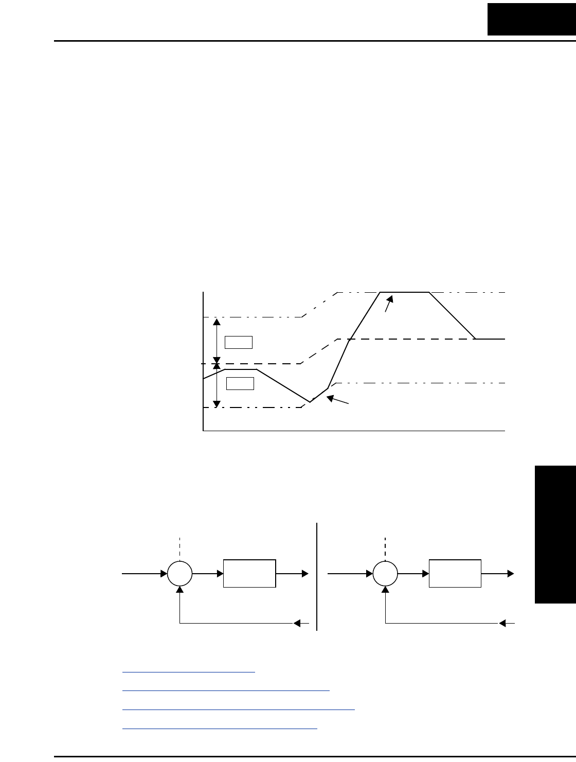
L2002 Inverter
Operations
and Monitoring
4–57
PID Loop Configuration
The inverter’s PID loop algorithm is configurable for various applications.
PID Output Limit - The PID loop controller has a built-in output limit function. This
function monitors the difference between the PID setpoint and the loop output (inverter
output frequency), measured as a percentage of the full scale range of each. The limit is
specified by parameter A078.
• When the difference |(Setpoint – loop output)| is smaller than or equal to the A078
limit value, the loop controller operates in its normal linear range.
• When the difference |(Setpoint – loop output)| is larger than the A078 limit value, the
loop controller changes the output frequency as needed so that the difference does not
exceed the limit.
The diagram below shows PID setpoint changes and the related output frequency
behavior when a limit value in A078 exists.
Error Inversion - In typical heating loops or ventilation loops, an increase in energy
into the process results in an increasing PV. In this case, the Loop Error = (SP – PV). For
cooling loops, an increase in energy into the process results in a decreasing PV. In this
case, the Loop Error = –(SP – PV). Use A077 to configure the error term.
Other PID-related topics:
•“PID Control” on page 3–24
•“PID ON/OFF and PID Clear” on page 4–28
•“Output Deviation for PID Control” on page 4–42
•“PID Second Stage Output” on page 4–46
Limit value
PID Setpoint
t
A078
Limit value
A078
Output limit
Output limit
%
Limit imposed
on output
Limit imposed
on output
Output frequency
∑
PID
Calculation
SP Error Freq.
PV from process with
positive correlation
PV
+
–
A077 = 00
∑
PID
Calculation
SP Error Freq.
PV from process with
negative correlation
PV
–
+
A077 = 01
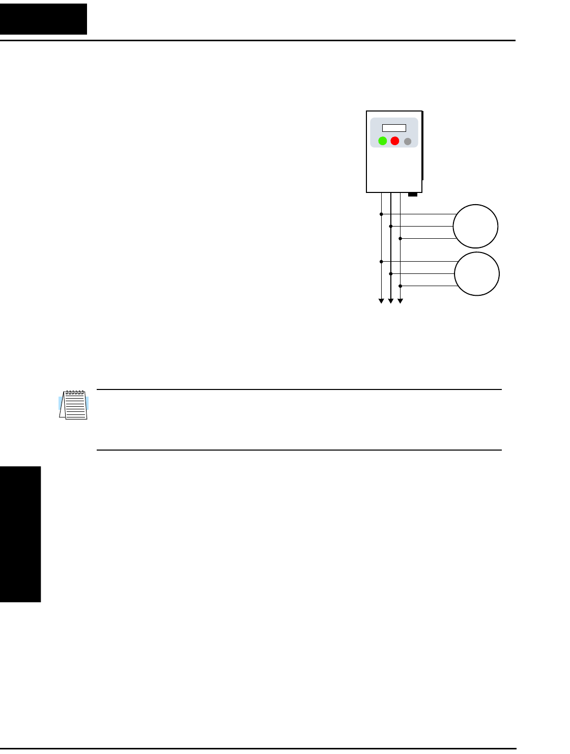
Configuring the Inverter for Multiple Motors
Operations
and Monitoring
4–58
Configuring the Inverter for Multiple Motors
Simultaneous Connections
For some applications, you may need to connect two
or more motors (wired in parallel) to a single inverter’s
output. For example, this is common in conveyor
applications where two separate conveyors need to
have approximately the same speed. The use of two
motors may be less expensive than making the
mechanical link for one motor to drive multiple
conveyors.
Some of the characteristics of using multiple motors
with one drive are:
• The inverter output must be rated to handle the sum
of the currents from the motors.
• You must use separate thermal protection switches
or devices to protect each motor. Locate the device
for each motor inside the motor housing or as close
to it as possible.
• The wiring for the motors must be permanently connected in parallel (do not remove
one motor from the circuit during operation).
NOTE: The motor speeds are identical only in theory. That is because slight differences
in their loads will cause one motor to slip a little more than another, even if the motors
are identical. Therefore, do not use this technique for multi-axis machinery that must
maintain a fixed position reference between its axes.
Inverter Configuration for Two Motor Types
Some equipment manufacturers may have a single type of machine that has to support
two different motor types—and only one motor will be connected at a time. For
example, an OEM may sell basically the same machine to the US market and the
European market. Some reasons why the OEM needs two motor profiles are:
• The inverter power input voltage is different for these markets.
• The required motor type is also different for each destination.
In other cases, the inverter needs two profiles because the machine characteristics vary
according to these situations:
• Sometimes the motor load is very light and can move fast. Other times the motor load
is heavy and must move slower. Using two profiles allows the motor speed, accelera-
tion and deceleration to be optimal for the load and avoid inverter trip (fault) events.
• Sometimes the slower version of the machine does not have special braking options,
but a higher performance version does have braking features.
to Nth motor
U/T1
V/T2
W/T3 Motor 1
Motor 2
L2002
U/T1
V/T2
W/T3
L2002 Inverter
Operations
and Monitoring
4–59
Having two motor profiles lets you store two “personalities” for motors in one inverter’s
memory. The inverter allows the final selection between the two motor types to be made
in the field through the use of an intelligent input terminal function [SET]. This provides
an extra level of flexibility needed in particular situations. See the following table.
Parameters for the second motor have a function code of the form x2xx. They appear
immediately after the first motor’s parameter in the menu listing order. The following
table lists the parameters that have the second parameter register for programming.
Function Name
Parameter Codes
1st motor 2nd motor
Multi-speed frequency setting A020 A220
Acceleration (1) time setting F002 F202
Deceleration (1) time setting F003 F203
Acceleration (2) time setting A092 A292
Deceleration (2) time setting A093 A293
Select method to use Acc2/Dec2 A094 A294
Acc1 to Acc2 frequency transition point A095 A295
Dec1 to Dec2 frequency transition point A096 A296
Level of electronic thermal setting B012 B212
Electronic thermal characteristic B013 B213
Torque boost select A041 A241
Manual torque boost value A042 A242
Manual torque boost frequency adjustment A043 A243
V/f characteristic curve selection A044 A244
iSLV voltage gain A046 A246
iSLV slip compensation A047 A247
Base frequency setting A003 A203
Maximum frequency setting A004 A204
Frequency upper limit setting A061 A261
Frequency lower limit setting A062 A262
Motor capacity H003 H203
Motor poles setting H004 H204
Motor stabilization constant H006 H206


Introduction
Motor Control
Accessories
5–2
Introduction
A motor control system will obviously include a motor and inverter, as well as fuses for
safety. If you are connecting a motor to the inverter on a test bench just to get started,
that’s all you may need for now. But a fully developed system can also have a variety of
additional components. Some can be for noise suppression, while others may enhance
the inverter’s braking performance. The figure below shows a system with several
possible optional components, and the table gives part number information.
Thermal
switch
Breaker,
MCCB or
GFI
From power supply
Motor
L1 L2 L3
+1
+
Inverter
GND
T1 T2 T3
Note: The Hitachi part number series for accesso-
ries includes different sizes of each part type,
specified by the –x suffix. Hitachi product litera-
ture can help match size and rating of your
inverter to the proper accessory size.
Each inverter accessory comes with its own printed
instruction manual. Please refer to those manuals for
complete installation details. This chapter gives only an
overview of these optional system devices.
Name
Part No. Series
See
page
Europe,
Japan USA
AC reactor, input side ALI–xxx2 HRL–x 5–3
RF noise filter, input
side
ZCL–xxx ZCL–xxx 5–4
EMI filter (for CE) FFL100–xxx FFL100–xxx 5–4
Capacitive filter CFI–x CFI–x 5–4
DC link choke DCL–x–xx HDC–xxx 5–4
Braking resistor JRB–xxx–x
SRB–xxx–x
JRB–xxx–x
SRB–xxx–x
5–5
Braking resistor,
NEMA-rated
—HRB-x,
NSRBx00–x
NJRB–xxx
5–5
Resistance braking
unit
BRD–xxx BRD–xxx 5–5
RF noise filter, output
side
ZCL–xxx ZCL–xxx 5–4
AC reactor, output
side
ALI–x2–xxx HRL–xxx 5–3
LCR filter Combination:
ALI–x2–xxx
LPF–xxx
R–2–xxx
HRL–xxC 5–3
AC reactor
RF noise filter
EMI filter
Capacitive filter
–
DC link choke
Braking
unit
RF noise
filter
AC reactor, or
LCR filter

L2002 Inverter
Motor Control
Accessories
5–3
Component Descriptions
AC Reactors, Input Side
This is useful in suppressing harmonics induced on the power supply lines, or when the
main power voltage imbalance exceeds 3% (and power source capacity is more than
500 kVA), or to smooth out line fluctuations. It also improves the power factor.
In the following cases for a general-purpose inverter, a large peak current flows on the
main power supply side, and is able to destroy the inverter module:
• If the unbalanced factor of the power supply is 3% or higher
• If the power supply capacity is at least 10 times greater than the inverter capacity (the
power supply capacity is 500 kVA or more)
• If abrupt power supply changes are expected
Examples of these situations include:
1. Several inverters are connected in parallel, sharing the same power bus
2. A thyristor converter and an inverter are connected in parallel, sharing the same
power bus
3. An installed phase-advance (power factor correction) capacitor opens and closes
Where these conditions exist or when the connected equipment must be highly reliable,
you MUST install an input-side AC reactor of 3% (at a voltage drop at rated current)
with respect to the supply voltage on the power supply side. Also, where the effects of an
indirect lightning strike are possible, install a lightning conductor.
Example calculation:
VRS = 205V, VST = 203V, VTR = 197V,
where VRS is R-S line voltage, VST is S-T line voltage, VTR is T-R line voltage
Please refer to the documentation that comes with the AC reactor for installation instruc-
tions.
AC Reactors, Output Side
This reactor reduces the vibrations in the motor caused by the inverter’s switching
waveforms, by smoothing the waveforms to approximate commercial power quality. It is
also useful to reduce the reflected voltage wave phenomenon when wiring from the
inverter to the motor is more than 10m in length. Please refer to the documentation that
comes with the AC reactor for installation instructions.
Unbalance factor of voltage Max. line voltage (min.) Mean line voltage–
Meanline voltage
----------------------------------------------------------------------------------------------------------- 100×=
VRS VRS VST VTR
++()3⁄–
VRS VST VTR
++()3⁄
-------------------------------------------------------------------100×=205 202–
202
------------------------100×1.5%==
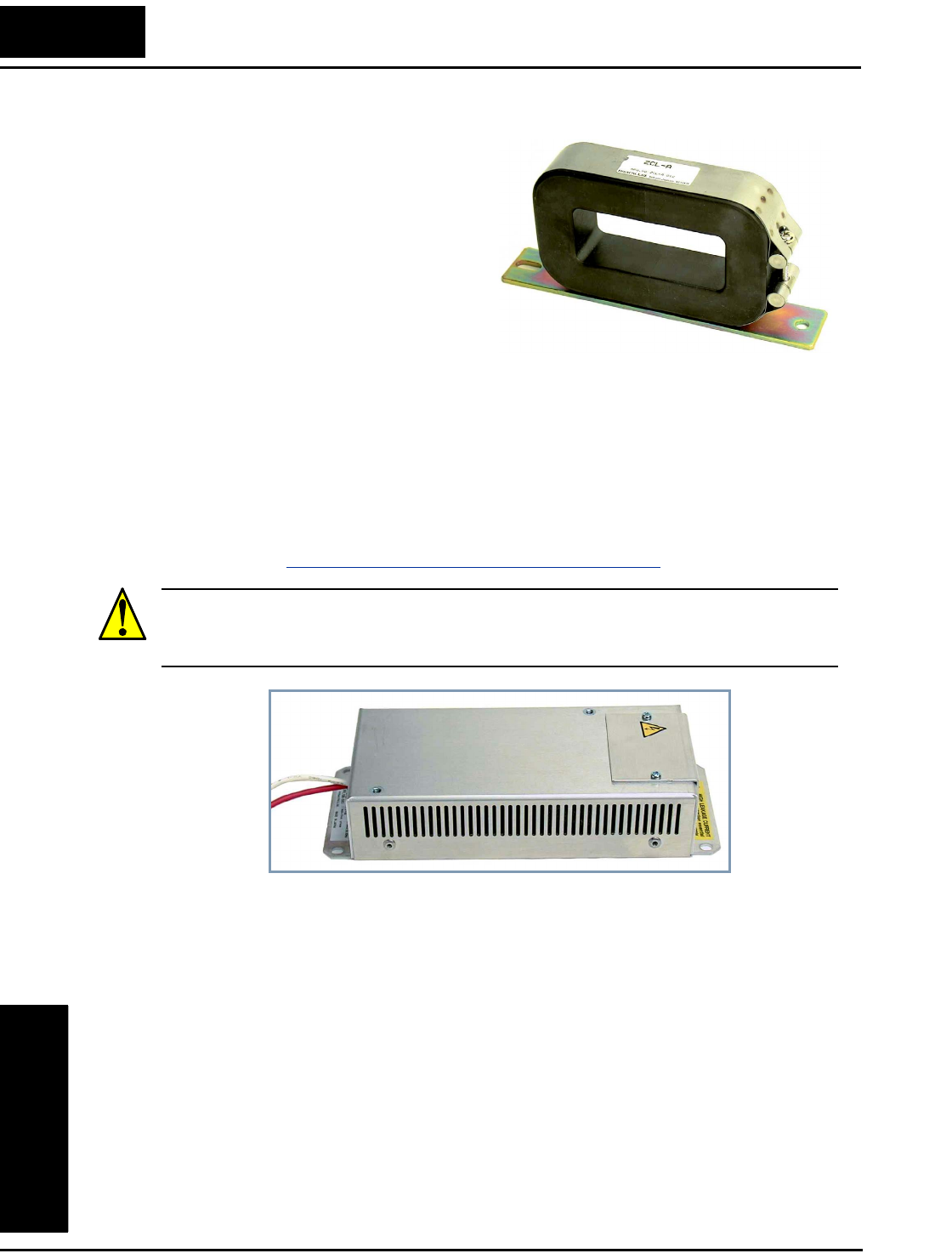
Component Descriptions
Motor Control
Accessories
5–4
Zero-phase Reactor (RF Noise Filter)
The zero-phase reactor helps reduce
radiated noise from the inverter wiring. It
can be used on the input or output side of
the inverter. The example zero-phase
reactor shown to the right comes with a
mounting bracket. The wiring must go
through the opening to reduce the RF
component of the electrical noise. Loop
the wires three times (four turns) to attain
the full RF filtering effect. For larger wire
sizes, place multiple zero-phase reactors
(up to four) side-by-side for a greater
filtering effect.
EMI Filter
The EMI filter reduces the conducted noise on the power supply wiring generated by the
inverter. Connect the EMI filter to the inverter primary (input side). The FFL100 series
filter is required for compliance to the EMC Class A directive (Europe) and C-TICK
(Australia). See “CE–EMC Installation Guidelines” on page D–2.
WARNING: The EMI filter has high internal leakage current from power wiring to the
chassis. Therefore, connect the chassis ground of the EMI filter before making the power
connections to avoid danger of shock or injury.
RF Noise Filter (Capacitive)
This capacitive filter reduces radiated noise from the main power wires in the inverter
input side. This filter is not for achieving CE compliance and is applicable to the input
side only of the inverter. It comes in two versions—for 200V class inverters or 400V
class inverters. Please refer to the documentation that comes with the radio noise filter
for installation instructions.
DC Link Choke
The DC choke (reactor) suppresses harmonics generated by the inverter. It attenuates the
high-frequency components on the inverter’s internal DC bus (link). However, note that
it does not protect the diode rectifiers in the inverter input circuit.
ZCL–xxx
FFL100–xxx

L2002 Inverter
Motor Control
Accessories
5–5
Dynamic Braking
Introduction
The purpose of dynamic braking is to improve the ability of the inverter to stop (deceler-
ate) the motor and load. This becomes necessary when an application has some or all of
the following characteristics:
• High load inertia compared to the available motor torque
• The application requires frequent or sudden changes in speed
• System losses are not great enough to slow the motor as needed
When the inverter reduces its output frequency to decelerate the load, the motor can
temporarily become a generator. This occurs when the motor rotation frequency is
higher than the inverter output frequency. This condition can cause the inverter DC bus
voltage to rise, resulting in an over-voltage trip. In many applications, the over-voltage
condition serves as a warning signal that we have exceeded the deceleration capabilities
of the system. The L2002 inverter can connect to an external braking unit, which sends
the regenerative energy from the motor during deceleration to the optional braking resis-
tor(s). The dynamic braking resistor serves as a load, developing heat to stop the motor
just as brakes on an automobile develop heat during braking.
A switching circuit and power resistor are the main components of the dynamic braking
unit that includes a fuse and thermally activated alarm relay for safety. However, be
careful to avoid overheating its resistor. The fuse and thermal relay are safeguards for
extreme conditions, but the inverter can maintain braking usage in a safe zone.
Dynamic Braking Usage
Dynamic braking usage must follow guide-
lines to avoid overheating. The timing diagram
to the right shows the output frequency versus
time. Dynamic braking is in effect during the
deceleration ramp, and has the following
constraints:
• Dynamic braking maximum duty cycle
= 10%, where Tb/Tc ≤ 0.1 sec.
Dynamic braking maximum continuous ON
time Tb ≤ 10 sec.
Selecting Braking Resistors for External Braking Units
200V Class Inverters – The following tables
specify the braking options for 200V class
L2002 inverters and the braking torque for
each option. You can connect a single braking
unit to the inverter, or two braking units for
additional stopping torque.
Output
freq.
Tbt
Tc
Dynamic braking
Inverter
+
–
Braking
unit
Braking
unit
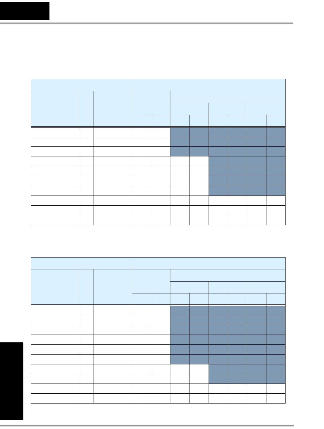
Dynamic Braking
Motor Control
Accessories
5–6
Use one BRD–E2 braking unit for the braking torque listed in the following table.
Note the column meanings in the tables:
• Column “A” = Average braking torque from 60 Hz to 3 Hz.
• Column “B” = Average braking torque from 120 Hz to 3 Hz
Connect a second braking unit in parallel for additional braking torque listed in the
following table.
L2002 Inverter 200V Models Braking Torque with BRD–E2 Braking Unit
Model Number HP
Braking
torque
without
braking unit
Using built-in
resistor only
External resistor added
HRB1 HRB2 HRB3
A B A B A B A B
002NFE(F)2/NFU2 1/4 50% 150% 120%
004NFE(F)2/NFU2 1/2 50% 150% 120%
005NFE(F)2/NFU2 3/4 50% 150% 120%
007NFE(F)2/NFU2 1 50% 100% 80% 150% 120%
011NFE(F)2/NFU2 1.5 50% 60% 60% 100% 80%
015NFE(F)2/NFU2 2 50% 50% 50% 100% 80%
022NFE(F)2/NFU2 3 20% 50% 50% 100% 80%
037LFU2 5 20% 40% 40% 60% 60% 100% 100% 150% 120%
055LFU2 7.5 20% 30% 30% 50% 50% 70% 70% 100% 80%
075LFU2 10 20% 20% 20% 40% 40% 50% 50% 80% 80%
L2002 Inverter 200V Models Braking Torque with TWO (2) BRD–E2 Braking Units
Model Number HP
Braking
torque
without
braking unit
Using built-in
resistor only
External resistor added
HRB1 HRB2 HRB3
A B A B A B A B
002NFE(F)2/NFU2 1/4 50% 150% 120%
004NFE(F)2/NFU2 1/2 50% 150% 120%
005NFE(F)2/NFU2 3/4 50% 150% 120%
007NFE(F)2/NFU2 1 50% 150% 120%
011NFE(F)2/NFU2 1.5 50% 100% 80%
015NFE(F)2/NFU2 2 50% 100% 80%
022NFE(F)2/NFU2 3 20~40% 70% 70% 150% 120%
037LFU2 5 20~40% 50% 50% 110% 90%
055LFU2 7.5 20% 30% 30% 80% 80% 100% 100% 150% 150%
075LFU2 10 20% 30% 30% 60% 60% 80% 80% 100% 100%
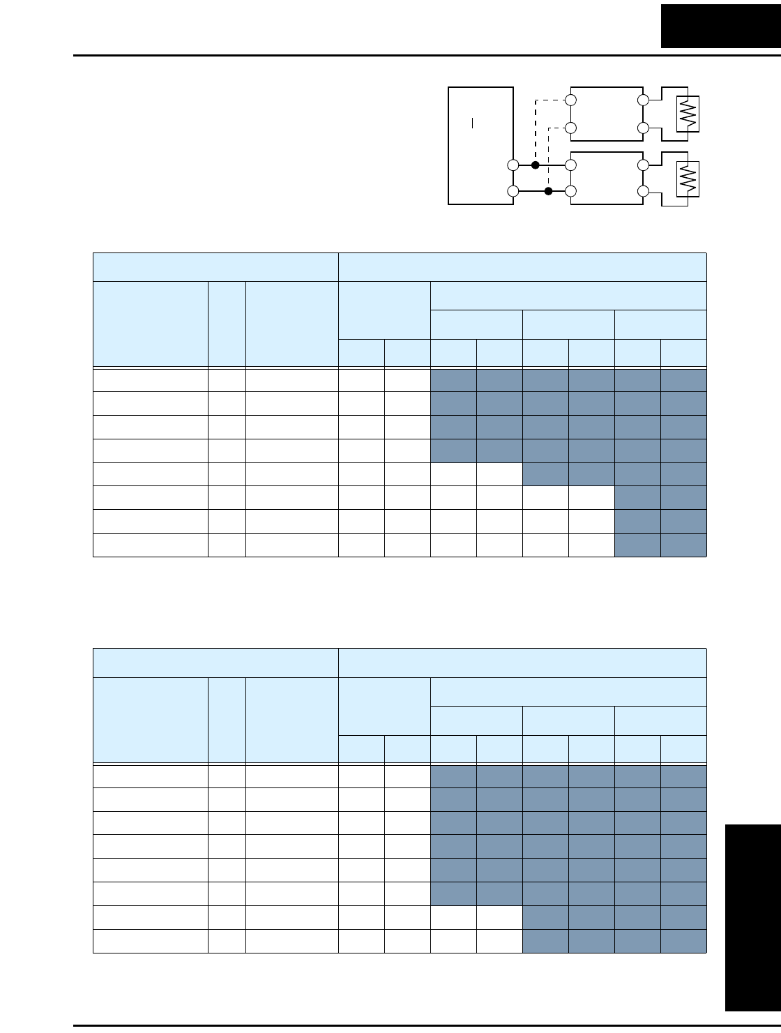
L2002 Inverter
Motor Control
Accessories
5–7
400V Class Inverters – The following tables
specify the braking options for 400V class
L2002 inverters and the braking torque for
each option. You can connect a single braking
unit to the inverter, or two braking units for
additional braking torque.
Use one BRD–EZ2 braking unit for the
braking torque listed in the following table.
Connect a second braking unit in parallel for additional braking torque listed in the
following table.
Inverter
+
–
Braking
unit
Braking
unit
L2002 Inverter 400V Models Braking Torque with BRD–EZ2 Braking Unit
Model Number HP
Braking
torque
without
braking unit
Using built-in
resistor only
External resistor added
HRB1 x (2) HRB2 x (2) HRB3 x (2)
A B A B A B A B
004HFE(F)2/HFU2 1/2 50% 150% 150%
007HFE(F)2/HFU2 1 50% 150% 150%
015HFE(F)2/HFU2 2 50% 100% 100%
022HFE(F)2/HFU2 3 20% 60% 60%
030HFE(F)2/HFU2 4 20% 50% 50% 150% 150%
040HFE(F)2/HFU2 5 20% 40% 40% 130% 130% 150% 150%
055HFE(F)2/HFU2 7.5 20% 30% 30% 100% 100% 130% 130%
075HFE(F)2/HFU2 10 20% 20% 20% 70% 70% 100% 100%
L2002 Inverter 400V Models Braking Torque with TWO (2)BRD–EZ2 Braking Units
Model Number HP
Braking
torque
without
braking unit
Using built-in
resistor only
External resistor added
HRB1 x (2) HRB2 x (2) HRB3 x (2)
A B A B A B A B
004HFE(F)2/HFU2 1/2 50% 150% 150%
007HFE(F)2/HFU2 1 50% 150% 150%
015HFE(F)2/HFU2 2 50% 150% 150%
022HFE(F)2/HFU2 3 20% 130% 130%
030HFE(F)2/HFU2 4 20% 100% 100%
040HFE(F)2/HFU2 5 20% 70% 70%
055HFE(F)2/HFU2 7.5 20% 50% 50% 150% 150%
075HFE(F)2/HFU2 10 20% 40% 40% 140% 140%


Troubleshooting
and Maintenance
In This Chapter.... page
— Troubleshooting............................................... 2
— Monitoring Trip Events, History, & Conditions . 5
— Restoring Factory Default Settings ................. 8
— Maintenance and Inspection ........................... 9
— Warranty........................................................ 16
6

Troubleshooting
Troubleshooting
and Maintenance
6–2
Troubleshooting
Safety Messages
Please read the following safety messages before troubleshooting or performing mainte-
nance on the inverter and motor system.
WARNING: Wait at least five (5) minutes after turning OFF the input power supply
before performing maintenance or an inspection. Otherwise, there is the danger of
electric shock.
WARNING: Make sure that only qualified personnel will perform maintenance, inspec-
tion, and part replacement. Before starting to work, remove any metallic objects from
your person (wristwatch, bracelet, etc.). Be sure to use tools with insulated handles.
Otherwise, there is a danger of electric shock and/or injury to personnel.
WARNING: Never remove connectors by pulling on its wire leads (wires for cooling
fan and logic P.C.board). Otherwise, there is a danger of fire due to wire breakage and/or
injury to personnel.
General Precautions and Notes
• Always keep the unit clean so that dust or other foreign matter does not enter the
inverter.
• Take special care in regard to breaking wires or making connection mistakes.
• Firmly connect terminals and connectors.
• Keep electronic equipment away from moisture and oil. Dust, steel filings and other
foreign matter can damage insulation, causing unexpected accidents, so take special
care.
Inspection Items
This chapter provides instructions or checklists for these inspection items:
• Daily inspection
• Periodic inspection (approximately once a year)
• Insulation resistance test

L2002 Inverter
Troubleshooting
and Maintenance
6–3
Troubleshooting Tips
The table below lists typical symptoms and the corresponding solution(s).
Symptom/condition Probable Cause Solution
The motor
will not run.
The inverter
outputs [U], [V],
[W] are not
supplying
voltage.
•Is the frequency command source
A001 parameter setting correct?
•Is the Run command source A002
parameter setting correct?
•Make sure the parameter
setting A001 is correct.
•Make sure the parameter
setting A002 is correct.
•Is power being supplied to termi-
nals [L1], [L2], and [L3/N]? If so,
the POWER lamp should be ON.
•Check terminals [L1], [L2],
and [L3/N], then [U/T1],
[V/T2], and [W/T3].
•Turn ON the power supply
or check fuses.
•Is there an error code E X X
displayed?
•Press the Func. key and
determine the error type.
Eliminate the error cause,
then clear the error (Reset).
•Are the signals to the intelligent
input terminals correct?
•Is the Run Command active?
•Is the [FW] terminal (or [RV])
connected to [PCS] (via switch,
etc.)
•Verify the terminal functions
for C001 – C005 are correct.
•Turn ON Run Command
enable.
•Supply 24V to [FW] or [RV]
terminal, if configured.
•Has the frequency setting for F001
been set greater than zero?
•Are the control circuit terminals
[H], [O], and [L] connected to the
potentiometer?
•Set the parameter for F001
to a safe, non-zero value.
•If the potentiometer is the
frequency setting source,
verify voltage at [O] > 0V.
•Is the RS (reset) function or FRS
(free-run stop) function ON?
•Turn OFF the command(s).
Inverter outputs
[U], [V], [W]
are supplying
voltage.
•Is the motor load too heavy? •Reduce load, and test the
motor independently.
The optional
remote operator
is used (SRW).
•Are the operational settings
between the remote operator and
the inverter unit correct?
•Check the operator type
setting.
The direction of the motor is
reversed.
•Are the connections of output
terminals [U/T1], [V/T2], and
[W/T3] correct?
•Is the phase sequence of the motor
forward or reverse with respect to
[U/T1], [V/T2], and [W/T3]?
•Make connections according
to the phase sequence of the
motor. In general:
FWD = U-V-W, and
REV=U-W-V.
•Are the control terminals [FW] and
[RV] wired correctly?
•Is parameter F004 properly set?
•Use terminal [FW] for
forward, and [RV] for
reverse.
•Set motor direction in F004.

Troubleshooting
Troubleshooting
and Maintenance
6–4
The motor speed will not reach
the target frequency (desired
speed).
•If using the analog input, is the
current or voltage at [O] or [OI]?
•Check the wiring.
•Check the potentiometer or
signal generating device.
•Is the load too heavy? •Reduce the load.
•Heavy loads activate the
overload restriction feature
(reduces output as needed).
•Is the inverter internally limiting
the output frequency?
•Check max frequency
setting (A004)
•Check frequency upper limit
setting (A061)
The rotation is unstable.
•Is the load fluctuation too great?
•Is the supply voltage unstable?
•Is the problem occurring at a partic-
ular frequency?
•Increase the motor capacity
(both inverter and motor).
•Fix power supply problem.
•Change the output frequency
slightly, or use the jump
frequency setting to skip the
problem frequency.
The RPM of the motor does not
match the inverter output
frequency setting.
•Is the maximum frequency setting
A004 correct?
•Does the monitor function D001
display the expected output
frequency?
•Verify the V/f settings match
motor specifications.
•Make sure all scaling (such
as A011 to A014) is
properly set.
Inverter data
is not
correct.
No downloads
have occurred.
•Was power turned OFF after a
parameter edit but before pressing
the Store key?
•Edit the data and press the
Store key once.
•Edits to data are permanently
stored at power down. Was the time
from power OFF to power ON less
than six seconds?
•Wait six seconds or more
before turning power OFF
after editing data.
A download to
the inverter was
attempted.
•Was the power turned OFF within
six seconds after the display
changed from REMT to INV?
•Copy the data to the inverter
again, and keep power ON
for six seconds or more after
copying.
A parameter
will not
change after
an edit
(reverts to
old setting).
True for certain
parameters
•Is the inverter in Run Mode? Some
parameters cannot be edited during
Run Mode.
•Put inverter in Stop Mode
(press the Stop/reset key).
Then edit the parameter.
True for all
parameters
•If you’re using the [SFT] intelligent
input (software lock function)—is
the [SFT] input ON?
•Change the state of the SFT
input, and check the B031
parameter (SFT mode).
Symptom/condition Probable Cause Solution
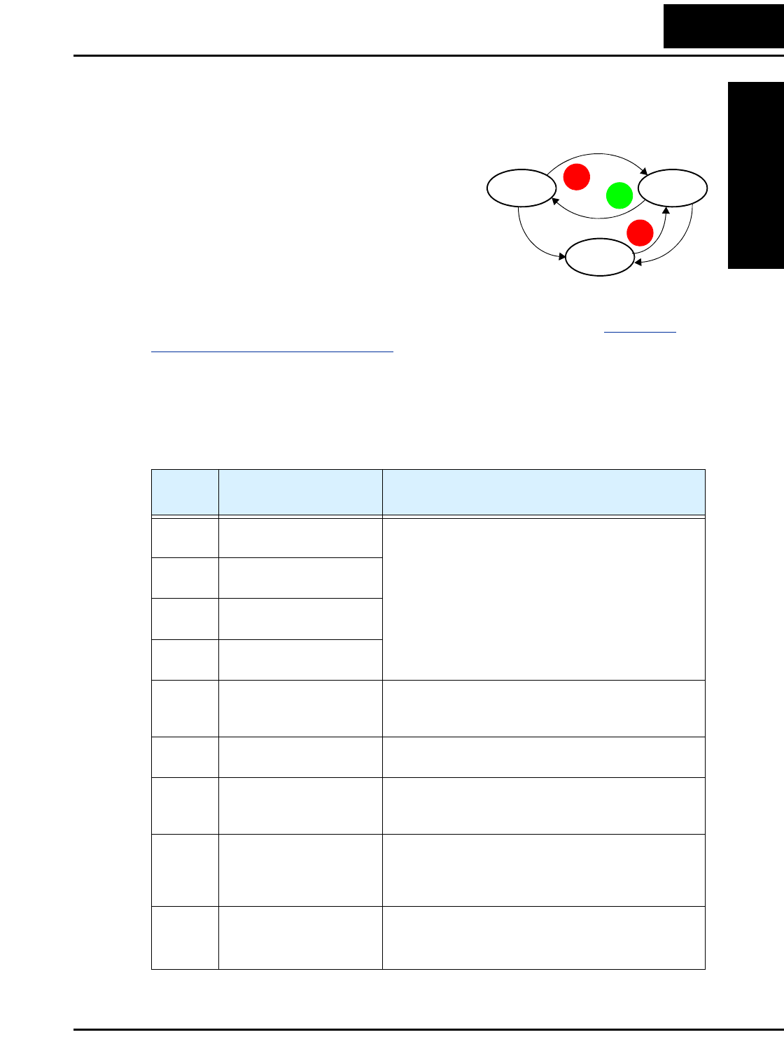
L2002 Inverter
Troubleshooting
and Maintenance
6–5
Monitoring Trip Events, History, & Conditions
Fault Detection and Clearing
The microprocessor in the inverter detects a variety
of fault conditions and captures the event, record-
ing it in a history table. The inverter output turns
OFF, or “trips” similar to the way a circuit breaker
trips due to an over-current condition. Most faults
occur when the motor is running (refer to the
diagram to the right). However, the inverter could
have an internal fault and trip in Stop Mode. In
either case, you can clear the fault by pressing the Stop/Reset key. Additionally, you can
clear the inverter’s cumulative trip history by performing the procedure “Restoring
Factory Default Settings” on page 6–8 (setting B084=00 will clear the trip history but
leave inverter settings intact).
Error Codes
An error code will appear on the display automatically when a fault causes the inverter to
trip. The following table lists the cause associated with the error.
Run Stop
Trip
Fault
Fault
STOP
RESET
STOP
RESET
RUN
Error
Code Name Cause(s)
E01 Over-current event while
at constant speed
The inverter output was short-circuited, or the motor
shaft is locked or has a heavy load. These conditions
cause excessive current for the inverter, so the inverter
output is turned OFF.
The dual-voltage motor is wired incorrectly.
E02 Over-current event during
deceleration
E03 Over-current event during
acceleration
E04 Over-current event during
other conditions
E05 Overload protection When a motor overload is detected by the electronic
thermal function, the inverter trips and turns OFF its
output.
E07 Over-voltage protection When the DC bus voltage exceeds a threshold, due to
regenerative energy from the motor.
E08 EEPROM error When the built-in EEPROM memory has problems
due to noise or excessive temperature, the inverter
trips and turns OFF its output to the motor.
E09 Under-voltage error A decrease of internal DC bus voltage below a thresh-
old results in a control circuit fault. This condition can
also generate excessive motor heat or cause low
torque. The inverter trips and turns OFF its output.
E1 1
E22
CPU error A malfunction in the built-in CPU has occurred, so
the inverter trips and turns OFF its output to the
motor.
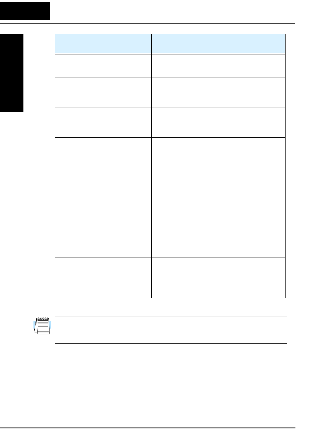
Monitoring Trip Events, History, & Conditions
Troubleshooting
and Maintenance
6–6
NOTE: If an EEPROM error (E08) occurs, be sure to confirm the parameter data values
are still correct. If the power is turned OFF while the [RS] (Reset) intelligent input
terminal is ON, an EEPROM error will occur when power is restored.
E1 2 External trip A signal on an intelligent input terminal configured as
EXT has occurred. The inverter trips and turns OFF
the output to the motor.
E1 3 USP When the Unattended Start Protection (USP) is
enabled, an error occurred when power is applied
while a Run signal is present. The inverter trips and
does not go into Run Mode until the error is cleared.
E1 4 Ground fault The inverter is protected by the detection of ground
faults between the inverter output and the motor upon
during powerup tests. This feature protects the
inverter, and does not protect humans.
E1 5 Input over-voltage The inverter tests for input over-voltage after the
inverter has been in Stop Mode for 100 seconds. If an
over-voltage condition exists, the inverter enters a
fault state. After the fault is cleared, the inverter can
enter Run Mode again.
E21 Inverter thermal trip When the inverter internal temperature is above the
threshold, the thermal sensor in the inverter module
detects the excessive temperature of the power
devices and trips, turning the inverter output OFF.
E30 Driver error An internal inverter error has occurred at the safety
protection circuit between the CPU and main driver
unit. Excessive electrical noise may be the cause. The
inverter has turned OFF the IGBT module output.
E35 Thermistor When a thermistor is connected to terminals [6] and
[L] and the inverter has sensed the temperature is too
high, the inverter trips and turns OFF the output.
E60 Communications error The inverter’s watchdog timer for the communica-
tions network has timed out.
--- Under-voltage (brown-
out) with output shutoff
Due to low input voltage, the inverter turns its output
OFF and tries to restart. If it fails to restart, then the
alarm trips to record the under-voltage error event.
Error
Code Name Cause(s)
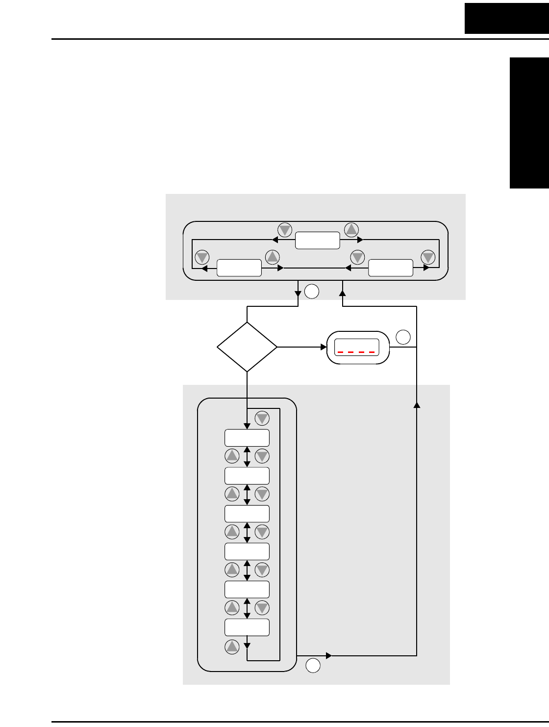
L2002 Inverter
Troubleshooting
and Maintenance
6–7
Trip History and Inverter Status
We recommend that you first find the cause of the fault before clearing it. When a fault
occurs, the inverter stores important performance data at the moment of the fault. To
access the data, use the monitor functions (Dxxx) and select D081 for details about the
present fault (En). The previous two faults are stored in D082 and D083, with D(En-1 and
En-2). Each error shifts D081–D082 to D082–D083, and writes the new error to D081.
The following Monitor Menu map shows how to access the error codes. When fault(s)
exist, you can review their details by first selecting the proper function: D081 is the most
recent, and D083 is the oldest.
2
1
Error Code
Output frequency
at trip point
Motor current
at trip point
DC bus voltage
at trip point
No error
Ye s
No
2
1
2
2
d
081
d
083
d
082
284.0
Monitor Menu
Trip
Conditions
Error
exists?
2
1
2
1
2
1
15
2
1
2
1
18
2
1
Cumulative inverter
operation time at
trip point
Cumulative power-
ON time at trip point
FUNC.
FUNC.
FUNC.
2.5
10.0
E09
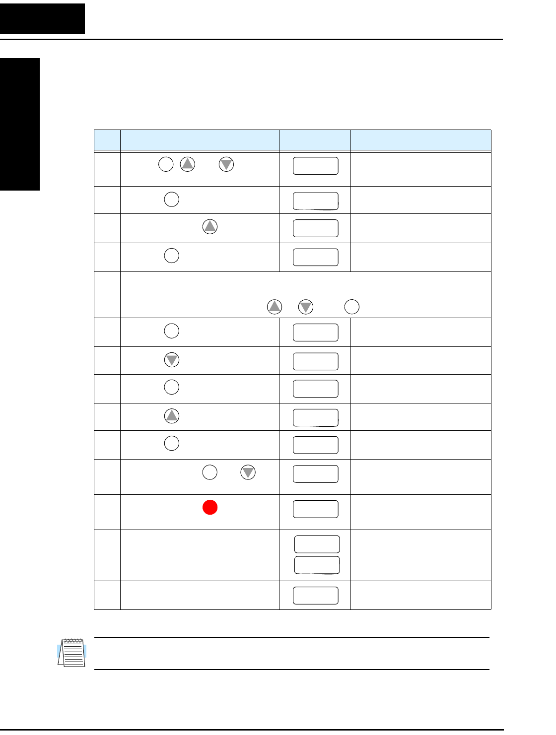
Restoring Factory Default Settings
Troubleshooting
and Maintenance
6–8
Restoring Factory Default Settings
You can restore all inverter parameters to the original factory (default) settings for the
intended country of use. After initializing the inverter, use the powerup test in Chapter 2
to get the motor running again. To initialize the inverter, follow the steps below.
NOTE: Initialization cannot be performed with a remote operator panel. Disconnect the
device and use the inverter’s front panel keypad.
No. Action Display Func./Parameter
1Use the , , and keys to
navigate to the “B” Group.
“B” Group selected
2Press the key. First “B” parameter selected
3Press and hold the key until -> Country code for initialization
selected
4Press the key. 00 = Japan, 01 = Europe,
02 = USA
5 Confirm the country code is correct. Do not change it unless you are absolutely sure the
power input voltage range and frequency match the country code setting.
To change the country code, press or to set, to store.
6Press the key. Country code for initialization
selected
7Press the key. Initialization function selected
8Press the key. 00 = initialization disabled,
clear trip history only
9Press the key. 01 = initialization enabled
10 Press the key. Initialization now enabled to
restore all defaults
11 Press and hold the and
keys. Do not release yet.
First part of special key
sequence
12 Press and hold the key for 3
seconds and then release.
Final part of key sequence;
display is blinking
13 After the display “D000” is blinking,
only then release all the keys.
Default parameter country code
shown during initialization
process (left-most char displays
alternating pattern)
14 Initialization is complete. Function code for output
frequency monitor shown
FUNC.
12
b
–––
FUNC.
b
001
1
b
085
FUNC.
02
12
STR
FUNC.
b
085
2
b
084
FUNC.
00
1
01
STR
b
084
FUNC.
2
b
084
STOP
RESET
d
000
EU
USA
d
001

L2002 Inverter
Troubleshooting
and Maintenance
6–9
Maintenance and Inspection
Monthly and Yearly Inspection Chart
Note 1: The life of a capacitor is affected by the ambient temperature. See “Capacitor
Life Curve” on page 6–11.
Note 2: The inverter must be cleaned periodically. If dust accumulates on the fan and
heat sink, it can cause overheating of the inverter.
Item Inspected Check for...
Inspection Cycle Inspection
Method Criteria
Month Ye a r
Overall
Ambient
environment
Extreme
temperatures
& humidity
✔Thermometer,
hygrometer
Ambient temperature
between -10 to 40°C,
non-condensing
Major devices Abnormal
noise & vib.
✔Visual and aural Stable environment for
electronic controls
Power supply
voltage
Voltage
tolerance
✔Digital volt meter,
measure between
inverter terminals
[L1], [L2], [L3]
200V class:
200 to 240V 50/60 Hz
400V class:
380 to 460V 50/60 Hz
Main
circuit
Ground
Insulation
Adequate
resistance
✔Digital volt meter,
GND to terminals
5 Meg. Ohms or greater
Mounting No loose
screws
✔Torque wrench M3: 0.5 – 0.6 Nm
M4: 0.98 – 1.3 Nm
M5: 1.5 – 2.0 Nm
Components Overheating ✔Thermal trip events No trip events
Housing Dirt, dust ✔Visual Vacuum dust and dirt
Terminal block Secure
connections
✔Visual No abnormalities
Smoothing
capacitor
Leaking,
swelling
✔Visual No abnormalities
Relay(s) Chattering ✔Aural Single click when
switching ON or OFF
Resistors Cracks or
discoloring
✔Visual Check Ohms of
optional braking res.
Cooling fan Noise ✔Power down,
manually rotate
Rotation must be
smooth
Dust ✔Visual Vacuum to clean
Control
circuit
Overall No odor,
discoloring,
corrosion
✔Visual No abnormalities
Capacitor No leaks or
deformation
✔Visual Undistorted appearance
Display LEDs Legibility ✔Visual All LED segments work
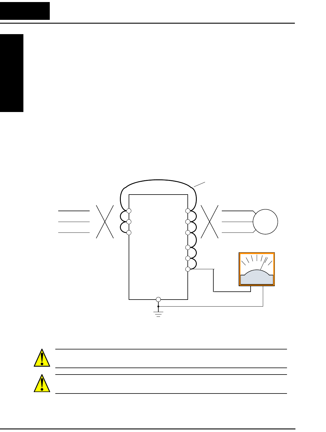
Maintenance and Inspection
Troubleshooting
and Maintenance
6–10
Megger Test
The megger is a piece of test equipment that uses a high voltage to determine if an
insulation degradation has occurred. For inverters, it is important that the power termi-
nals be isolated from the Earth GND terminal via the proper amount of insulation.
The circuit diagram below shows the inverter wiring for performing the megger test. Just
follow the steps to perform the test:
1. Remove power from the inverter and wait at least 5 minutes before proceeding.
2. Open the front housing panel to access the power wiring.
3. Remove all wires to terminals [R, S, T, PD/+1, PD/+, N/–, U, V, and W]. Most impor-
tantly, the input power and motor wires will be disconnected from the inverter.
4. Use a bare wire and short terminals [R, S, T, PD/+1, PD/+, N/–, U, V, and W] together
as shown in the diagram.
5. Connect the megger to the inverter Earth GND and to the shorted power terminals as
shown. Then perform the megger test at 500 VDC and verify 5MΩ or greater resis-
tance.
6. After completing the test, disconnect the megger from the inverter.
7. Reconnect the original wires to terminals [R, S, T, PD/+1, PD/+, N/–, U, V, and W].
CAUTION: Do not connect the megger to any control circuit terminals such as intelli-
gent I/O, analog terminals, etc. Doing so could cause damage to the inverter.
CAUTION: Never test the withstand voltage (HIPOT) on the inverter. The inverter has a
surge protector between the main circuit terminals above and the chassis ground.
Megger, 500VDC
L2002
Disconnect
power source
R
S
T
U
V
W
Disconnect
motor wires
Motor
Earth GND
PD/+1
PD/+
N/–
Add test jumper wire
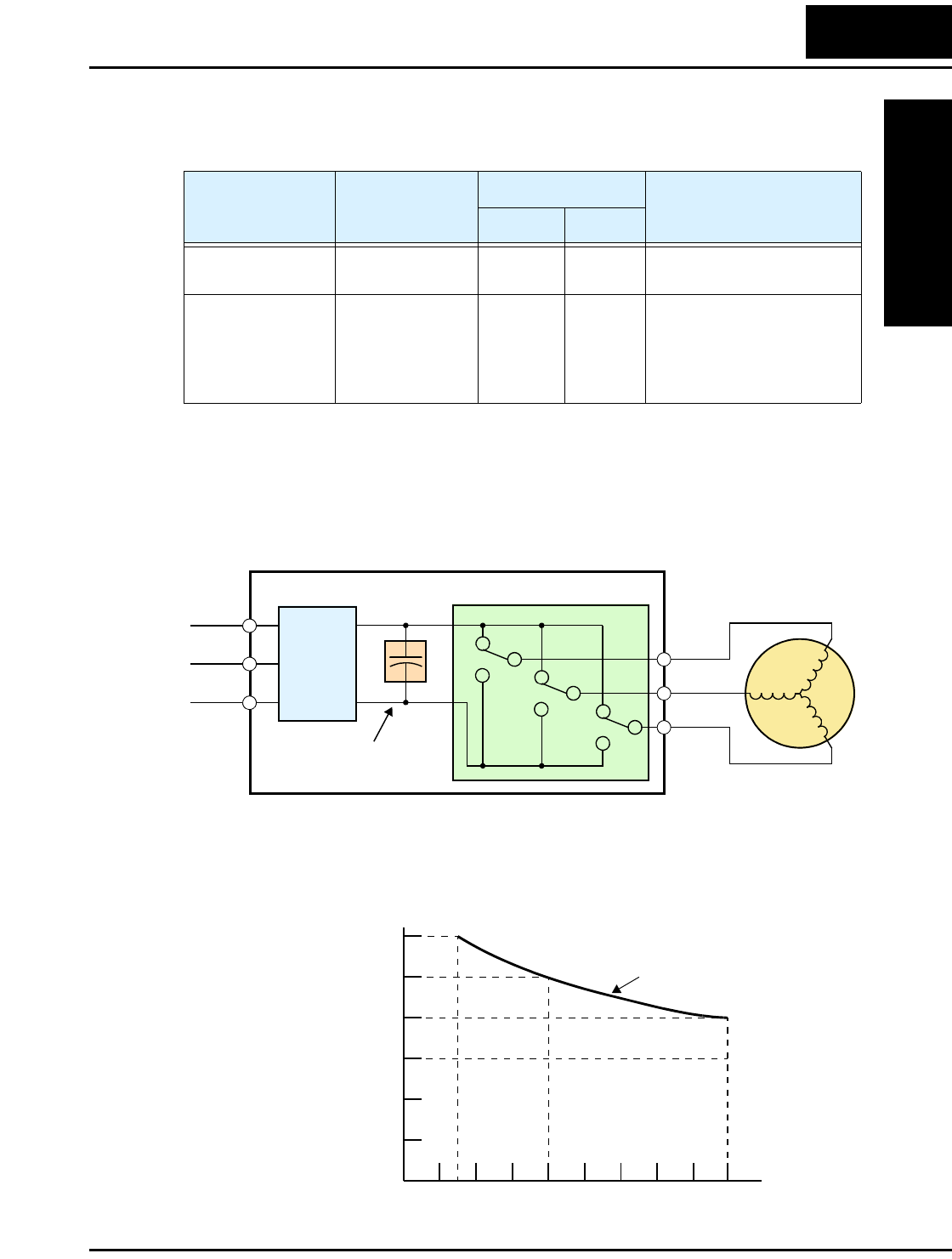
L2002 Inverter
Troubleshooting
and Maintenance
6–11
Spare parts
We recommend that you stock spare parts to reduce down time, including these parts:
Capacitor Life Curve
The DC bus inside the inverter uses a large capacitor as shown in the diagram below. The
capacitor handles high voltage and current as it smooths the power for use by the
inverter. So, any degradation of the capacitor will affect the performance of the inverter.
Capacitor life is reduced in higher ambient temperatures, as the graph below demon-
strates. Be sure to keep the ambient temperature at acceptable levels, and perform
maintenance inspections on the fan, heat sink, and other components. If the inverter is
installed on a cabinet, the ambient temperature is the temperature inside the cabinet.
Part description Symbol
Quantity
Notes
Used Spare
Cooling fan FAN 1 1 015NF, 022NF, 037LF,
015HF to 075HF
Case CV 1 1 •Front case
•Key cover
•Case
•Bottom cover
Power
Input Inverter
L1 Motor
L2
L3
Rectifier
Variable-frequency Drive
Internal
DC Bus
+
+
–
U/T1
V/T2
W/T3
Converter
Capacitor
Ambient
temperature, °C
Ye a r s
Capacitor Life Curve
Operation for 12 hours/day
40
30
20
10
0
-10
1234 5678910
50
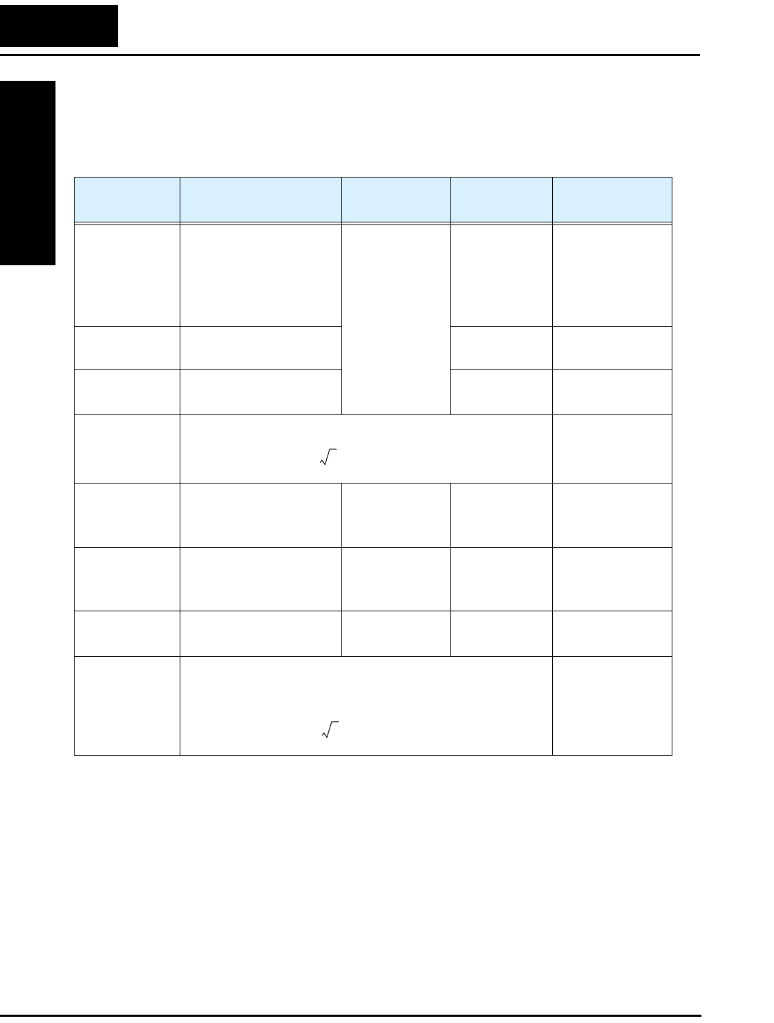
Maintenance and Inspection
Troubleshooting
and Maintenance
6–12
General Inverter Electrical Measurements
The following table specifies how to measure key system electrical parameters. The
diagrams on the next page show inverter-motor systems and the location of measurement
points for these parameters.
Note 1: Use a meter indicating a fundamental wave effective value for voltage, and
meters indicating total effective values for current and power.
Note 2: The inverter output has a distorted waveform, and low frequencies may cause
erroneous readings. However, the measuring instruments and methods listed
above provide comparably accurate results.
Note 3: A general-purpose digital volt meter (DVM) is not usually suitable to measure
a distorted waveform (not pure sinusoid).
Parameter Circuit location
of measurement
Measuring
instrument Notes Reference Value
Supply voltage
E1
ER – across L1 and L2
ES – across L2 and L3
ET – across L3 and L1
Moving-coil
type voltmeter or
rectifier type
voltmeter
Fundamental
wave effective
value
Commercial
supply voltage
(200V class) 200–
240V, 50/60 Hz
400V class 380–
460V, 50/60 Hz
Supply current
I1
Ir – L1, Is – L2, It – L3 Total effective
value
—
Supply power
W1
W11 – across L1 and L2
W12 – across L2 and L3
Total effective
value
—
Supply power
factor Pf1
—
Output voltage
E0
EU – across U and V
EV – across V and W
EW – across W and U
Rectifier type
voltmeter
Total effective
value
—
Output current
Io
IU – U
IV – V
IW – W
Moving-coil
ammeter
Total effective
value
—
Output power
Wo
W01 – across U and V
W02 – across V and W
Electronic type
wattmeter
Total effective
value
—
Output power
factor Pfo
Calculate the output power factor from the output voltage E,
output current I, and output power W.
—
Pf1
W1
3E
1
×I1
×
------------------------------100%×=
Pf0
W0
3E
0
×I0
×
------------------------------100%×=
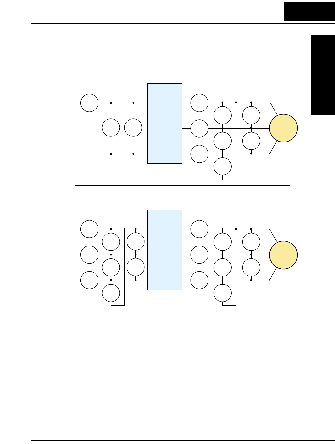
L2002 Inverter
Troubleshooting
and Maintenance
6–13
The figures below show measurement locations for voltage, current, and power measure-
ments listed in the table on the previous page. The voltage to be measured is the funda-
mental wave effective voltage. The power to be measured is the total effective power.
E1W1
I1I1
I1
I1
EU-V
EU-V
EU-V
W01
W02
E1
I1I1
I1
I1
EU-V
EU-V
EU-V
W01
W02
W01
W02
E1
E1
I2
I3
Single-phase Measurement Diagram
Three-phase Measurement Diagram
L1
N
L1
N
U
V
W
T1
T2
T3
Inverter
Motor
T1
T2
T3
U
V
W
R
S
T
Inverter
Motor
L1
L2
L3
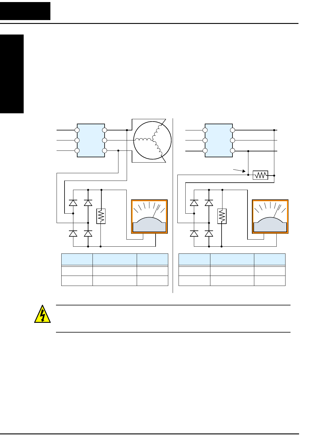
Maintenance and Inspection
Troubleshooting
and Maintenance
6–14
Inverter Output Voltage Measurement Techniques
Taking voltage measurements around drives equipment requires the right equipment and
a safe approach. You are working with high voltages and high-frequency switching
waveforms that are not pure sinusoids. Digital voltmeters will not usually produce
reliable readings for these waveforms. And, it is usually risky to connect high voltage
signals to oscilloscopes. The inverter output semiconductors have some leakage, and
no-load measurements produce misleading results. So, we highly recommend using the
following circuits to measure voltage for performing the equipment inspections.
HIGH VOLTAGE: Be careful not to touch wiring or connector terminals when working
with the inverters and taking measurements. Be sure to place the measurement circuitry
components above in an insulated housing before using them.
220 kΩ
2W
+–
220 kΩ
2W
+–
Voltage measurement with load
Inverter
Voltage measurement without load
Additional resistor
Inverter
5 kΩ
30W
V Class Diode Bridge Vo l t m et e r
200V Class 600V 0.01A min. 300V range
400V Class 100V 0.1A min. 600V range
V Class Diode Bridge Voltmeter
200V Class 600V 0.01A min. 300V range
400V Class 100V 0.1A min. 600V range
L1/R
L2/S
L3/T
U/T1
V/T2
W/T3
L1/R
L2/S
L3/T
U/T1
V/T2
W/T3
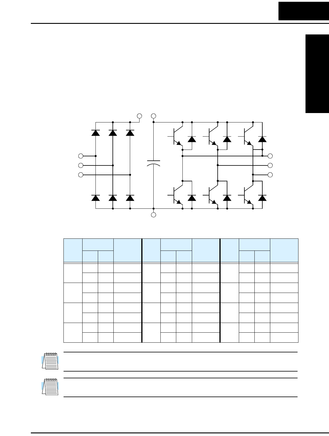
L2002 Inverter
Troubleshooting
and Maintenance
6–15
IGBT Test Method
The following procedure will check the inverter transistors (IGBTs) and diodes:
1. Disconnect input power to terminals [R, S, and T] and motor terminals [U, V, and W].
2. Disconnect any wires from terminals [+] and [–] for regenerative braking.
3. Use a Digital Volt Meter (DVM) and set it for 1Ω resistance range. You can check the
status of the charging state of terminals [R, S, T, U, V, W, +, and –] of the inverter and
the probe of the DVM by measuring the charging state.
Table Legend – Almost infinite resistance: ≅ ∞ Ω Almost zero resistance: ≅ 0 Ω
NOTE: The resistance values for the diodes or the transistors will not be exactly the
same, but they will be close. If you find a significant difference, a problem may exist.
NOTE: Before measuring the voltage between [+] and [–] with the DC current range,
confirm that the smoothing capacitor is discharged fully, then execute the tests.
Part
DVM Measured
Valu e Part
DVM Measured
Val ue Part
DVM Measured
Valu e
+ – + – + –
D1 [R] +1 ≅ ∞ Ω D5 [S] [N] ≅ 0 ΩTR3 [W] [+] ≅ ∞ Ω
+1 [R] ≅ 0 Ω[N] [S] ≅ ∞ Ω [+] [W] ≅ 0 Ω
D2 [S] +1 ≅ ∞ Ω D6 [T] [N] ≅ 0 ΩTR4 [U] [–] ≅ 0 Ω
+1 [S] ≅ 0 Ω[N] [T] ≅ ∞ Ω [–] [U] ≅ ∞ Ω
D3 [T] +1 ≅ ∞ Ω TR1 [U] [+] ≅ ∞ Ω TR5 [V] [–] ≅ 0 Ω
+1 [T] ≅ 0 Ω[+] [U] ≅ 0 Ω[–] [V] ≅ ∞ Ω
D4 [R] [N] ≅ 0 ΩTR2 [V] [+] ≅ ∞ Ω TR6 [W] [–] ≅ 0 Ω
[N] [R] ≅ ∞ Ω [+] [V] ≅ 0 Ω[–] [W] ≅ ∞ Ω
[R]
[S]
[T]
TR1 TR2 TR3
[U]
[V]
[W]
[–]
D1 D2 D3
D4 D5 D6
+
[+][+1]
TR4 TR5 TR6

Warranty
Troubleshooting
and Maintenance
6–16
Warranty
Warranty Terms
The warranty period under normal installation and handling conditions
shall be two (2) years from the date of manufacture (“DATE” on product
nameplate), or one (1) year from the date of installation, whichever occurs
first. The warranty shall cover the repair or replacement, at Hitachi's sole
discretion, of ONLY the inverter that was installed.
1. Service in the following cases, even within the warranty period, shall
be charged to the purchaser:
a. Malfunction or damage caused by mis-operation or modification
or improper repair
b. Malfunction or damage caused by a drop after purchase and
transportation
c. Malfunction or damage caused by fire, earthquake, flood,
lightening, abnormal input voltage, contamination, or other natural
disasters
2. When service is required for the product at your work site, all expenses
associated with field repair shall be charged to the purchaser.
3. Always keep this manual handy; please do not lose it. Please contact
your Hitachi distributor to purchase replacement or additional manuals.


Glossary
Appendix A
A–2
Glossary
Ambient Temperature The air temperature in the chamber containing a powered electronic
unit. A unit’s heat sinks rely on a lower ambient temperature in
order to dissipate heat away from sensitive electronics.
Arrival Frequency The arrival frequency refers to the set output frequency of the
inverter for the constant speed setting. The arrival frequency feature
turns on an output when the inverter reaches the set constant speed.
The inverter has various arrival frequencies and pulsed or latched
logic options.
Auto-tuning The ability of a controller to execute a procedure that interacts with
a load to determine the proper coefficients to use in the control
algorithm. Auto-tuning is a common feature of process controllers
with PID loops. Hitachi inverters feature auto tuning to determine
motor parameters for optimal commutation. Auto-tuning is avail-
able as a special command from a digital operator panel. See also
Digital Operator Panel.
Base Frequency The power input frequency for which an AC induction motor is
designed to operate. Most motors will specify a 50 to 60 Hz value.
The Hitachi inverters have a programmable base frequency, so you
must ensure that parameter matches the attached motor. The term
base frequency helps differentiate it from the carrier frequency. See
also Carrier Frequency and Frequency Setting.
Braking Resistor An energy-absorbing resistor that dissipates energy from a deceler-
ating load. Load inertia causes the motor to act as a generator
during deceleration. For the L2002 inverter models, the braking unit
and braking resistor are optional (external) components. See also
Four-quadrant Operation and Dynamic Braking.
Break-away Torque The torque a motor must produce to overcome the static friction of a
load, in order to start the load moving.
Carrier Frequency The frequency of the constant, periodic, switching waveform that
the inverter modulates to generate the AC output to the motor. See
also PWM.
CE A regulatory agency for governing the performance of electronic
products in Europe. Drive installations designed to have CE
approval must have particular filter(s) installed in the application.
Choke An inductor that is tuned to react at radio frequencies is called a
“choke,” since it attenuates (chokes) frequencies above a particular
threshold. Tuning is often accomplished by using a movable
magnetic core. In variable-frequency drive systems, a choke
positioned around high-current wiring can help attenuate harmful
harmonics and protect equipment. See also Harmonics.

L2002 Inverter
Appendix A
A–3
DC Braking The inverter DC braking feature stops the AC commutation to the
motor, and sends a DC current through the motor windings in order
to stop the motor. Also called “DC injection braking,” it has little
effect at high speed, and is used as the motor is nearing a stop.
Deadband In a control system, the range of input change for which there is no
perceptible change in the output. In PID loops, the error term may
have a dead band associated with it. Deadband may or may not be
desirable; it depends on the needs of the application.
Digital Operator Panel For Hitachi inverters, “digital operator panel” (DOP) refers first to
the operator keypad on the front panel of the inverter. It also
includes hand-held remote keypads, which connect to the inverter
via a cable. Finally, the DOP Professional is a PC-based software
simulation of the keypad devices.
Diode A semiconductor device that has a voltage-current characteristic
that allows current to flow only in one direction, with negligible
leakage current in the reverse direction. See also Rectifier.
Duty Cycle 1. The percent of time a square wave of fixed frequency is ON
(high) versus OFF (low). 2. The ratio of operating time of a device
such as a motor to its resting time. This parameter usually is speci-
fied in association with the allowable thermal rise for the device.
Dynamic Braking For the L2002 inverter models, the braking unit and braking resistor
are optional (external) components. The dynamic braking feature
shunts the motor-generated EMF energy into a special braking
resistor. The added dissipation (braking torque) is effective at
higher speeds, having a reduced effect as the motor nears a stop.
Error In process control, the error is the difference between the desired
value or setpoint (SP) and the actual value of a the process variable
(PV). See also Process Variable and PID Loop.
EMI Electromagnetic Interference - In motor/drive systems, the switch-
ing of high currents and voltages creates the possibility of generat-
ing radiated electrical noise that may interfere with the operation of
nearby sensitive electrical instruments or devices. Certain aspects of
an installation, such as long motor lead wire lengths, tend to
increase the chance of EMI. Hitachi provides accessory filter
components you can install to decrease the level of EMI.
Four-quadrant
operation
Referring to a graph of torque versus direction, a four-quadrant
drive can turn the motor either forward or reverse, as well as decel-
erate in either direction (see also reverse torque). A load that has a
relatively high inertia and must move in both directions and change
directions rapidly requires four-quadrant capability from its drive.

Glossary
Appendix A
A–4
Free-run Stop A method of stopping a motor, caused when the inverter simply
turns OFF its motor output connections. This may allow the motor
and load to coast to a stop, or a mechanical brake may intervene and
shorten the deceleration time.
Frequency Setting While frequency has a broad meaning in electronics, it typically
refers to motor speed for variable-frequency drives (inverters). This
is because the output frequency of the inverter is variable, and is
proportional to the attained motor speed. For example, a motor with
a base frequency of 60 Hz can be speed controlled with an inverter
output varying form 0 to 60 Hz. See also Base Frequency, Carrier
Frequency, and Slip.
Harmonics A harmonic is a whole number multiple of a base of fundamental
frequency. The square waves used in inverters produce high-
frequency harmonics, even though the main goal is to produce
lower-frequency sine waves. These harmonics can be harmful to
electronics (including motor windings) and cause radiated energy
that interferes with nearby electronic devices. Chokes, line reactors,
and filters are sometimes used to suppress the transmission of
harmonics in an electrical system. See also Choke.
Horsepower A unit of physical measure to quantify the amount of work done per
unit of time. You can directly convert between horsepower and
Watts as measurements of power.
IGBT Insulated Gate Bipolar Transistor (IGBT) – A semiconductor
transistor capable of conducting very large currents when in satura-
tion and capable of withstanding very high voltages when it is OFF.
This high-power bipolar transistor is the type used in Hitachi invert-
ers.
Inertia The natural resistance a stationary object to being moved by an
external force. See also Momentum.
Intelligent Terminal A configurable input or output logic function on the Hitachi invert-
ers. Each terminal may be assigned one of several functions.
Inverter A device that electronically changes DC to AC current through an
alternating process of switching the input to the output, inverted and
non-inverted. A variable speed drive such as the Hitachi L2002 is
also called an inverter, since it contains three inverter circuits to
generate 3-phase output to the motor.
Isolation Transformer A transformer with 1:1 voltage ratio that provides electrical isola-
tion between its primary and secondary windings. These are
typically used on the power input side of the device to be protected.
An isolation transformer can protect equipment from a ground fault
or other malfunction of nearby equipment, as well as attenuate
harmful harmonics and transients on the input power.

L2002 Inverter
Appendix A
A–5
Jogging Operation Usually done manually, a jog command from an operator’s panel
requests the motor/drive system to run indefinitely in a particular
direction, until the machine operator ends the jog operation.
Jump Frequency A jump frequency is a point on the inverter output frequency range
that you want the inverter to skip around. This feature may be used
to avoid a resonant frequency, and you can program up to three
jump frequencies in the inverter.
Line Reactor A three-phase inductor generally installed in the AC input circuit of
an inverter to minimize harmonics and to limit short-circuit current.
Momentum The physical property of a body in motion that causes it to remain
in motion. In the case of motors, the rotor and attached load are
rotating and possesses angular momentum.
Multi-speed Operation The ability of a motor drive to store preset discrete speed levels for
the motor, and control motor speed according to the currently
selected speed preset. The Hitachi inverters have 16 preset speeds.
Motor Load In motor terminology, motor load consists of the inertia of the
physical mass that is moved by the motor and the related friction
from guiding mechanisms. See also Inertia.
NEC The National Electric Code is a regulatory document that governs
electrical power and device wiring and installation in the United
States.
NEMA The National Electric Manufacturer’s Association. NEMA Codes
are a published series of device ratings standards. Industry uses
these to evaluate or compare the performance of devices made by
various manufacturers to a known standard.
Open-collector Outputs A common logic-type discrete output that uses an NPN transistor
that acts as a switch to a power supply common, usually ground.
The transistor’s collector is open for external connection (not
connected internally). Thus, the output sinks external load current to
ground.
Power Factor A ratio that expresses a phase difference (timing offset) between
current and voltage supplied by a power source to a load. A perfect
power factor = 1.0 (no phase offset). Power factors less than one
cause some energy loss in power transmission wiring (source to
load).
PID Loop Proportional - Integral-Derivative - A mathematical model used for
process control. A process controller maintains a process variable
(PV) at a setpoint (SP) by using its PID algorithm to compensate for
dynamic conditions and vary its output to drive the PV toward the
desired value. For variable-frequency drives, the process variable is
the motor speed. See also Error.

Glossary
Appendix A
A–6
Process Variable A physical property of a process that is of interest because it affects
the quality of the primary task accomplished by the process. For an
industrial oven, temperature is the process variable. See also PID
Loop and Error.
PWM Pulse-width modulation: A type of AC adjustable frequency drive
that accomplishes frequency and voltage control at the output
section (inverter) of the drive. The drive output voltage waveform is
at a constant amplitude, and by “chopping” the waveform (pulse-
width-modulating), the average voltage is controlled. The chopping
frequency is sometimes called the Carrier Frequency.
Reactance The impedance of inductors and capacitors has two components.
The resistive part is constant, while the reactive part changes with
applied frequency. These devices have a complex impedance
(complex number), where the resistance is the real part and the
reactance is the imaginary part.
Rectifier An electronic device made of one or more diodes that converts AC
power into DC power. Rectifiers are usually used in combination
with capacitors to filter (smooth) the rectified waveform to closely
approximate a pure DC voltage source.
Regenerative Braking A particular method of generating reverse torque to a motor, an
inverter will switch internally to allow the motor to become a gener-
ator and will either store the energy internally, deliver the braking
energy back to the main power input, or dissipate it with a resistor.
Regulation The quality of control applied to maintain a parameter of interest at
a desired value. Usually expressed as a percent (±) from the
nominal, motor regulation usually refers to its shaft speed.
Reverse Torque The torque applied in the direction opposite to motor shaft rotation.
As such, reverse torque is a decelerating force on the motor and its
external load.
Rotor The windings of a motor that rotate, being physically coupled to the
motor shaft. See also Stator.
Saturation Voltage For a transistor semiconductor device, it is in saturation when an
increase in input current no longer results in an increase in the
output current. The saturation voltage is the voltage drop across the
device. The ideal saturation voltage is zero.
Sensorless Vector
Control
A technique used in some variable-frequency drives (featured in
some other Hitachi inverter model families) to rotate the force
vector in the motor without the use of a shaft position sensor
(angular). Benefits include an increase in torque at the lowest speed
and the cost savings from the lack of a shaft position sensor.

L2002 Inverter
Appendix A
A–7
Setpoint (SP) The setpoint is the desired value of a process variable of interest.
See also Process Variable (PV) and PID Loop.
Single-phase power An AC power source consisting of Hot and Neutral wires. An Earth
Ground connection usually accompanies them. In theory, the
voltage potential on Neutral stays at or near Earth Ground, while
Hot varies sinusoidally above and below Neutral. This power source
is named Single Phase to differentiate it from three-phase power
sources. Some Hitachi inverters can accept single phase input
power, but they all output three-phase power to the motor. See also
Three-phase.
Slip The difference between the theoretical speed of a motor at no load
(determined by its inverter output waveforms) and the actual speed.
Some slip is essential in order to develop torque to the load, but too
much will cause excessive heat in the motor windings and/or cause
the motor to stall.
Squirrel Cage A “nick-name” for the appearance of the rotor frame assembly for
an AC induction motor.
Stator The windings in a motor that are stationary and coupled to the
power input of the motor. See also Rotor.
Tachometer 1. A signal generator usually attached to the motor shaft for the
purpose of providing feedback to the speed controlling device of the
motor. 2. A speed-monitoring test meter that may optically sense
shaft rotation speed and display it on a readout.
Thermal Switch An electromechanical safety device that opens to stop current flow
when the temperature at the device reaches a specific temperature
threshold. Thermal switches are sometimes installed in the motor in
order to protect the windings from heat damage. The inverter can
use thermal switch signals to trip (shut down) if the motor
overheats. See also Trip.
Thermistor A type of temperature sensor that changes its resistance according
to its temperature. The sensing range of thermistors and their
ruggedness make them ideal for motor overheating detection.
Hitachi inverters have built-in thermistor input circuits, which can
detect an overheated motor and shut off (trip) the inverter output.
Three-phase power An AC power source with three Hot connections that have phase
offsets of 120 degrees is a 3-phase power source. Usually, Neutral
and Earth Ground wires accompany the three Hot connections.
Loads may be configured in a delta or Y configuration. A Y-
connected load such as an AC induction motor will be a balanced
load; the currents in all the Hot connections are the same. There-
fore, the Neutral connection is theoretically zero. This is why
inverters that generate 3-phase power for motors do not generally
have a Neutral connection to the motor. However, the Earth Ground
connection is important for safety reasons, and is provided.
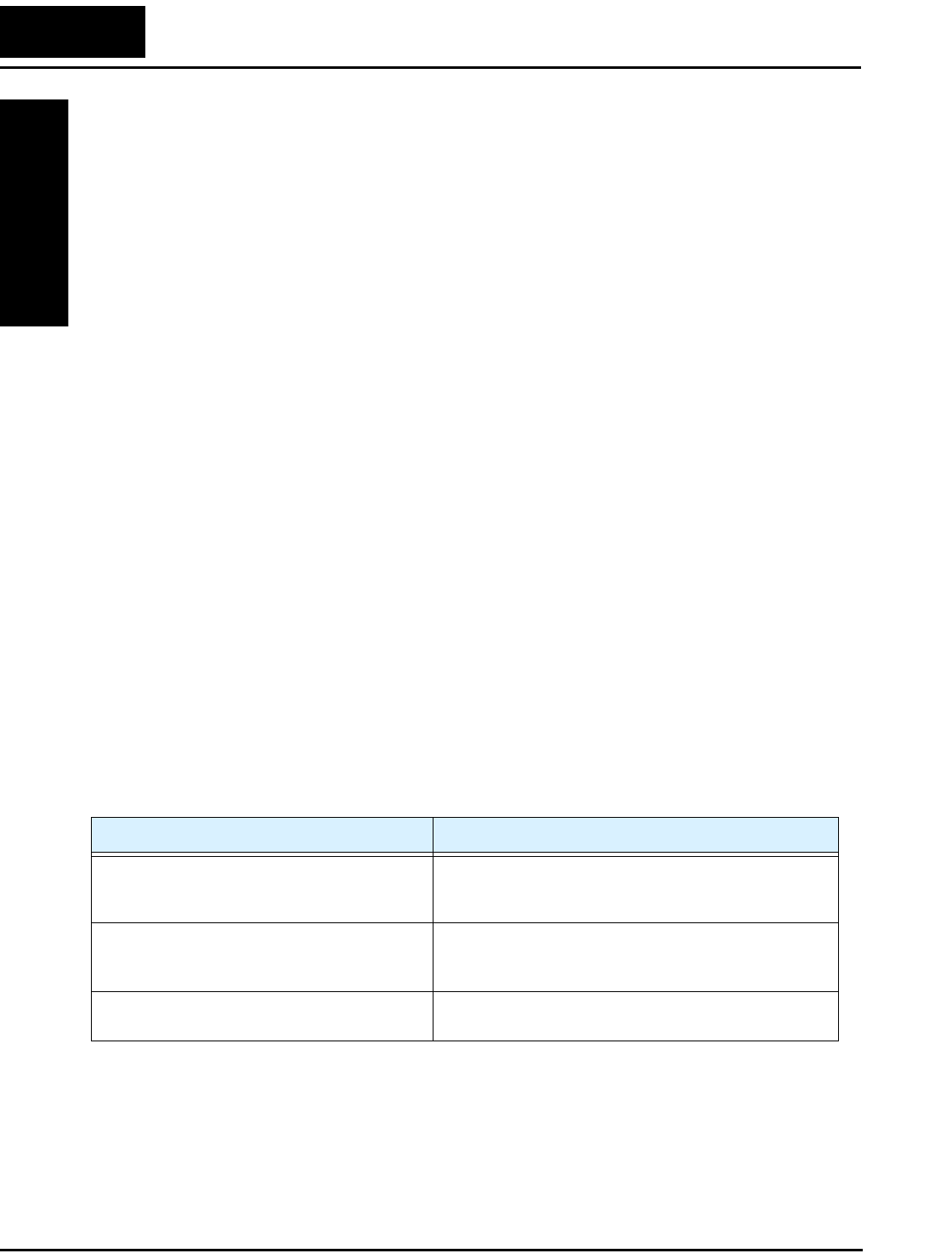
Bibliography
Appendix A
A–8
Torque The rotational force exerted by a motor shaft. The units of measure-
ment consist of the distance (radius from shaft center axis) and
force (weight) applied at that distance. Units are usually given as
pound-feet, ounce-inches, or Newton-meters.
Transistor A solid state, three-terminal device that provides amplification of
signals and can be used for switching and control. While transistors
have a linear operating range, inverters use them as high-powered
switches. Recent developments in power semiconductors have
produced transistors capable of handling high voltages and currents,
all with high reliability. The saturation voltage has been decreasing,
resulting in less heat dissipation. Hitachi inverters use state-of-the-
art semiconductors to provide high performance and reliability in a
compact package. See also IGBT and Saturation Voltage.
Trip Event An event that causes the inverter to stop operation is called a “trip”
event (as in tripping a circuit breaker). The inverter keeps a history
log of trip events. They also require an action to clear.
Watt Loss A measure of the internal power loss of a component, the difference
between the power it consumes and what its output delivers. An
inverter’s watt loss is the input power minus the power delivered to
the motor. The watt loss is typically highest when an inverter is
delivering its maximum output. Therefore, watt loss is usually
specified for a particular output level. Inverter watt loss specifica-
tions are important when designing enclosures.
Bibliography
Title Author and Publisher
Variable Speed Drive Fundamentals, 2nd Ed. Phipps, Clarence A.
The Fairmont Press, Inc. / Prentice-Hall, Inc. 1997
ISBN 0-13-636390-3
Electronic Variable Speed Drives Brumbach, Michael E.
Delmar Publishers 1997
ISBN 0-8273-6937-9
Hitachi Inverter Technical Guide Book Published by Hitachi, Ltd. Japan 1995
Publication SIG-E002

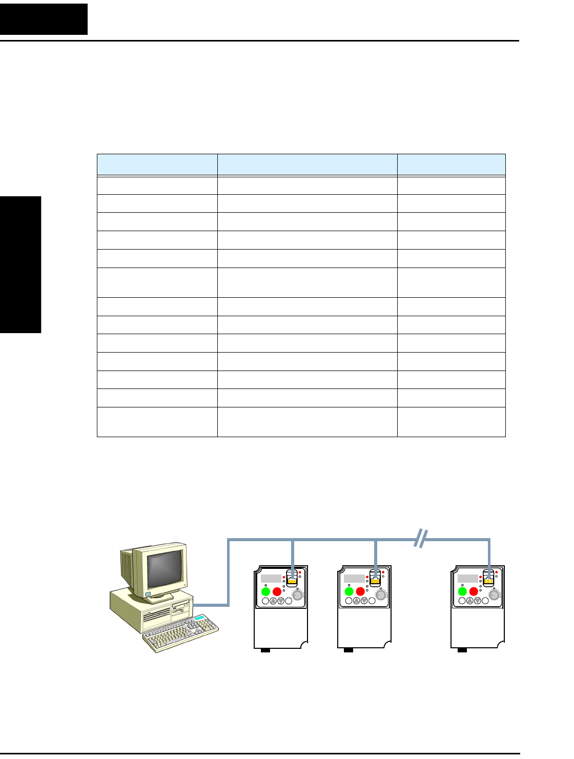
Introduction
Appendix B
B–2
Introduction
L2002 Series inverters have built-in RS-485 serial communications, featuring the
ModBus RTU protocol. The inverters can connect directly to existing factory networks
or work with new networked applications, without any extra interface equipment. The
specifications for L2002 serial communications are in the following table.
The network diagram below shows a series of inverters communicating with a host
computer. each inverter must have a unique address, from 1 to 32, on the network. In a
typical application, a host computer or controller is the master and each of the inverter(s)
or other devices is a slave.
Item Specifications User-selectable
Transmission speed 4800 / 9600 / 19200 bps ✔
Communication mode Asynchronous ✘
Character code Binary ✘
LSB placement Transmits LSB first ✘
Electrical interface RS-485 differential transceiver ✘
Data bits 8-bit (ModBus RTU mode) (ASCII mode not
available)
Parity None / even / odd ✔
Stop bits 1 or 2 bits ✔
Startup convention One-way start from host device ✘
Wait time for response 0 to 1000 msec. ✔
Connections Station address numbers from 1 to 32 ✔
Connector RJ45 modular jack —
Error check Overrun, Fleming block check code,
CRC-16, or horizontal parity
—
L2002
12
RUN STOP
RESET
FUNC.
STR
HITACHI
POWER
ALARM
RUN
A
Hz
PRG
5 0.0
L2002
12
RUN STOP
RESET
FUNC.
STR
HITACHI
POWER
ALARM
RUN
A
Hz
PRG
5 0.0
L2002
12
RUN STOP
RESET
FUNC.
STR
HITACHI
POWER
ALARM
RUN
A
Hz
PRG
5 0.0
1
ModBus Network
232
Host computer
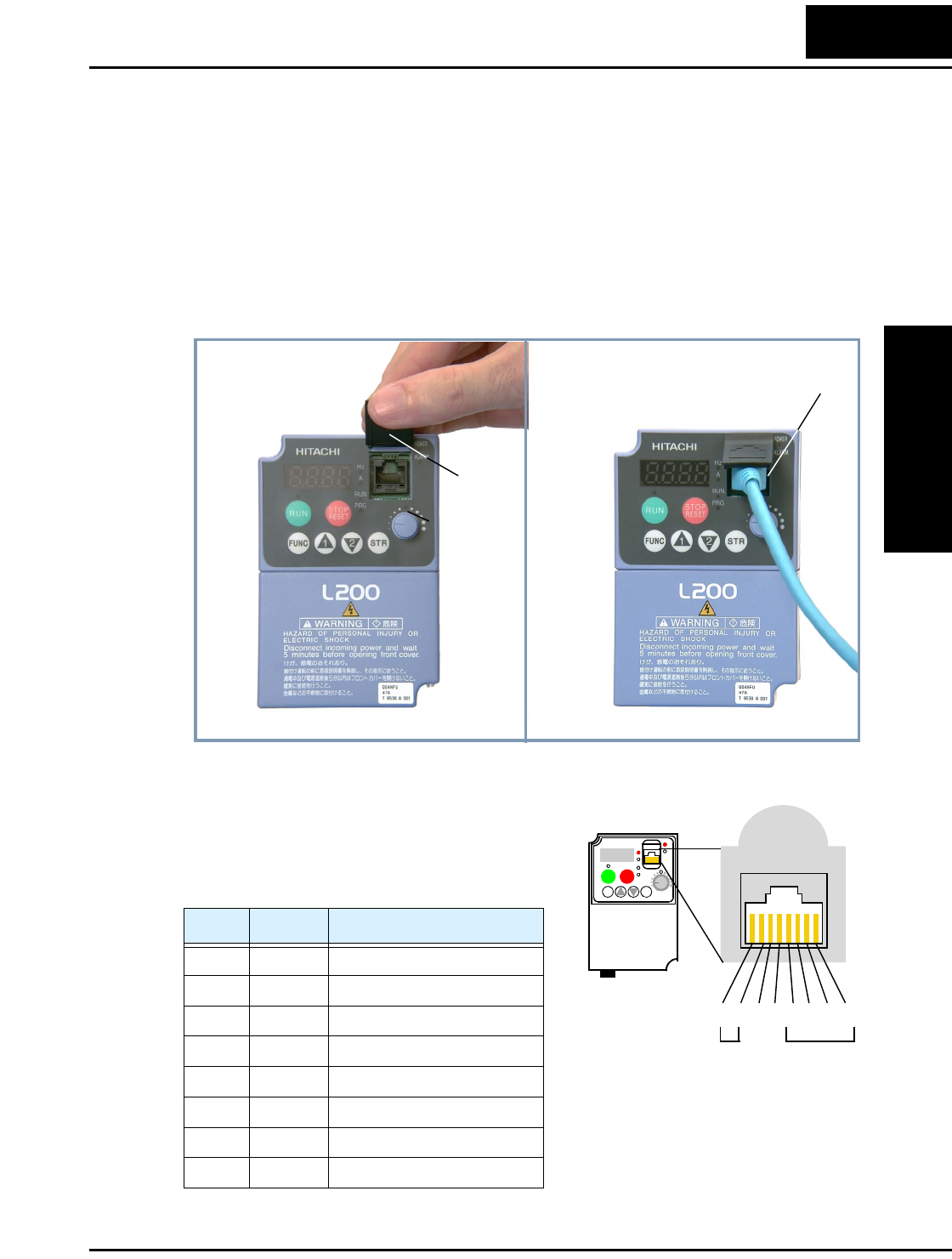
L2002 Inverter
Appendix B
B–3
Connecting the Inverter to ModBus
Follow the steps in this section to connect the inverter to the ModBus network.
1. Open Serial Port Cover - The inverter keypad has a hinged dust cover protecting the
serial port connector. Lift the cover from the bottom edge, and tilt upward as shown
(below left).
2. Modular Interconnect Removal - With the serial port cover opened, notice the RJ45
modular connector behind it. Connect the serial cable and engage the locking tab in
the connector as shown (below right).
3. Cable Wiring - The inverter communications
port uses RS485 differential transceiver. The
pinout is shown to the right and listed below. Be
sure the cable connection you make matches the
diagram.
Pin Symbol Description
1 — Not used. Do not connect
2 — Not used. Do not connect
3 — Not used. Do not connect
4 — Not used. Do not connect
5 SP Send/Receive data Positive
6 SN Send/Receive data Negative
7 — Not used. Do not connect
8 — Not used. Do not connect
RJ45 modular
communications
connector
Dust
cover
Serial cable with RJ45 end
L2002
12
RUN STOP
RESET
FUNC.
STR
HITACHI
POWER
ALARM
RUN
A
Hz
PRG
5 0.0
S
N
1
S
P
2345678
Not usedNot used
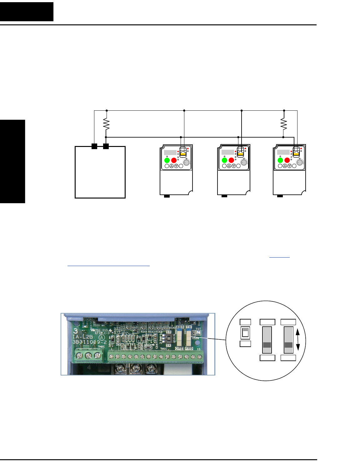
Connecting the Inverter to ModBus
Appendix B
B–4
4. Terminate Network Wiring - The RS-485 wiring must be terminated at each
physical end to suppress electrical reflections and help decrease transmission errors.
The L2002 communications port does not include a termination resistor. Therefore,
you will need to add termination to the inverter if it is at the end of the network
wiring. Select termination resistors that match the characteristic impedance of the
network cable. The diagram below shows a network with the needed termination
resistor at each end.
5. Set Inverter OPE/485 Switch - The inverter serial port accepts a connection to either
a remote keypad device or to the network. You will need to set the DIP switch on the
inverter to configure the port for ModBus communications. Setting the switch will
require removing the front housing cover. Remember to power OFF the inverter
before removing the cover or changing the DIP switch setting. Refer to “Front
Housing Cover” on page 2–3 for detailed instructions.
Locate the OPE/485 DIP switch as shown in the figure below. Carefully move the
switch to the upper position labeled “485” (slide in direction of arrow). Then replace
the front housing cover.
At this point the electrical network connection is complete. The next step will show
how to configure parameters and settings related to ModBus communications.
L2002
12
RUN STOP
RESET
FUNC.
STR
HITACHI
POWER
ALARM
RUN
A
Hz
PRG
5 0.0
L2002
12
RUN STOP
RESET
FUNC.
STR
HITACHI
POWER
ALARM
RUN
A
Hz
PRG
5 0.0
L2002
12
RUN STOP
RESET
FUNC.
STR
HITACHI
POWER
ALARM
RUN
A
Hz
PRG
5 0.0
ModBus
Network
Host device
SP SN
SR
SK
OPE
485
PRG
TM

L2002 Inverter
Appendix B
B–5
6. Inverter Parameter Setup - The inverter has several settings related to ModBus
communications. The table below lists them together. The Required column indicates
which parameters must be set properly to allow communications. You may need to
refer to the host computer documentation in order to match some of its settings.
NOTE: When you edit and store any of the parameters above, the inverter causes it to
take effect immediately. ModBus transmission occurs only after you set the OPE/485
DIP switch to the “485” position and turn on the inverter. Note that parameters C071 to
C078 cannot be changed via the network. To edit them, reconnect the inverter keypad (or
other digital operator) and edit the parameters.
Func.
Code Name Required Settings
A001 Frequency source setting ✔00... Keypad potentiometer
01... Control terminal
02... Function F001 setting
03... ModBus network input
10... Calculate function output
A002 Run command source setting ✔01...Control terminal
02... Run key on keypad, or digital operator
03... ModBus network input
B089 Monitor display select for
networked inverter
— 01... Output frequency monitor
02... Output current monitor
03... Rotation direction monitor
04... Process variable (PV), PID feedback
monitor
05... Intelligent input terminal status
06... Intelligent output terminal status
07... Scaled output frequency monitor
C071 Communication speed selection ✔04... 4800 bps
05... 9600 bps
06... 19200 bps
C072 Node allocation ✔Network address, range is 1 to 32
C074 Communication parity selection ✔00... No parity
01... Even parity
02... Odd parity
C075 Communication stop bit selection ✔Range is 1 to 2
C076 Communication error select — 00... Trip (error code E60)
01... Decelerate to a stop and trip (error code
E60)
02... Disable
03... Free run stop (coasting)
04... Decelerate to a stop
C077 Communication error time-out — Comm. watchdog timer period,
range is 0.00 to 99.99 sec.
C078 Communication wait time ✔Time the inverter waits after receiving a
message before it transmits.
Range is 0. to 1000. ms
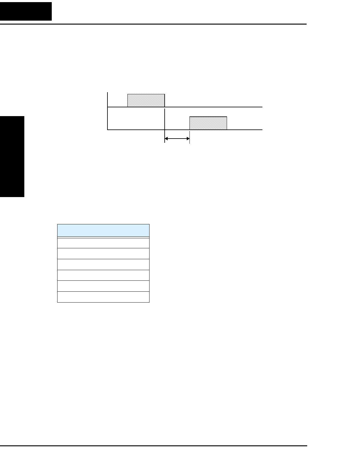
Network Protocol Reference
Appendix B
B–6
Network Protocol Reference
Transmission procedure
The transmission between the external control equipment and the inverter takes the
procedure below
• Query - A frame sent from the external control equipment to the inverter
• Response - A frame returned from inverter to the external control equipment
The inverter returns the response only after the inverter receives a query from the
external control equipment and does not output the response positively. Each frame is
formatted (with commands) as follows:
Message Configuration: Query
Slave address:
• This is a number of 1 to 32 assigned to each inverter (slave). (Only the inverter having
the address given as a slave address in the query can receive the query.)
• When slave address “0” is specified, the query can be addressed to all inverters simul-
taneously. (Broadcasting)
• In broadcasting, you cannot call and loop back data.
Frame Format
Header (silent interval)
Slave address
Function code
Data
Error check
trailer (silent interval)
Query
t
External control
equipment
Response
Inverter
Latency time
(silent interval plus C078 setting)

L2002 Inverter
Appendix B
B–7
Data:
• A function command is set here.
• The data format used in the L2002 series is corresponding to the Modbus data format
below.
Function code:
Specify a function you want to make the inverter execute. Function codes available to the
L2002 series are listed below.
Error check:
Modbus-RTU uses CRC (Cyclic Redundancy Check) for error checking.
• The CRC code is 16-bit data that is generated for 8-bit blocks of arbitrary length.
• The CRC code is generated by a generator polynomial CRC-16 (X16+ X15+ X2+ 1).
Header and trailer (silent interval):
Latency is the time between the reception of a query from the master and transmission of
a response from the inverter.
• 3.5 characters (24 bits) are always required for latency time. If the latency time shorter
than 3.5 characters, the inverter returns no response.
• The actual transmission latency time is the sum of silent interval (3.5 characters long)
+ C078 (transmission latency time).
Name of Data Description
Coil Binary data that can be referenced and changed (1 bit long)
Holding Register 16-bit data that can be referenced and changed
Function
Code Function
Maximum data size
(bytes available per
message)
Maximum number of
data elements available
per message
0 1 h Read Coil Status 4 32 coils (in bits)
0 3 h Read Holding Register 4 4 registers (in bytes)
0 5 h Write in Coil 1 1 coil (in bits)
0 6 h Write in Holding Register 1 1registers (in bytes)
0 8 h Loopback Test — —
0 F h Write in Coils 4 32 coils (in bits)
1 0 h Write in Registers 4 4 registers (in bytes)
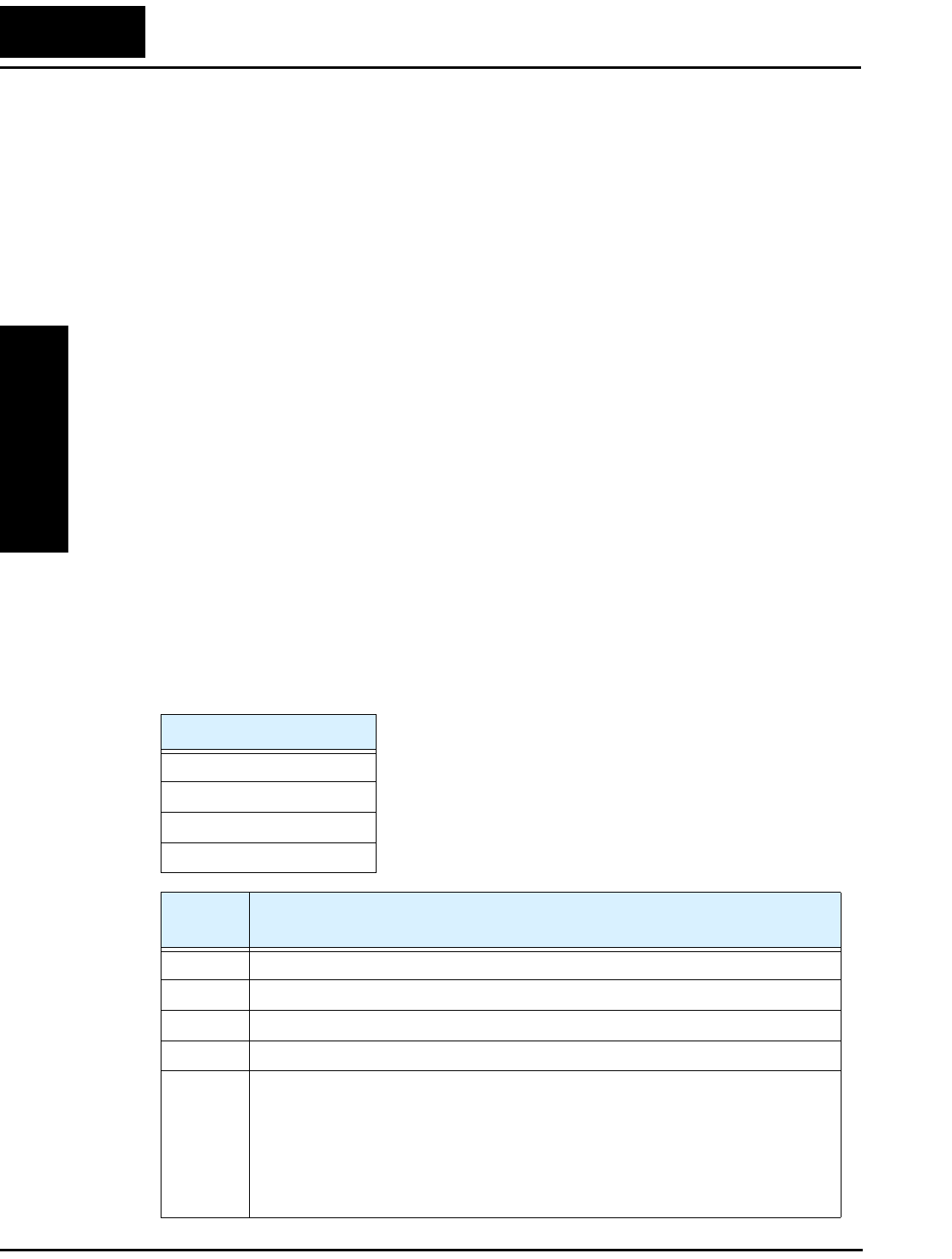
Network Protocol Reference
Appendix B
B–8
Message Configuration: Response
Transmission time required:
• A time period between reception of a query from the master and transmission of a
response from the inverter is the sum of the silent interval (3.5 characters long) + C078
(transmission latency time).
• The master must provide a time period of the silent interval (3.5 characters long or
longer) before sending another query to an inverter after receiving a response from the
inverter.
Normal response:
• When receiving a query that contains a function code of Loopback (08h), the inverter
returns a response of the same content of the query.
• When receiving a query that contains a function code of Write in Register or Coil
(05h, 06h, 0Fh, or 10h), the inverter directly returns the query as a response.
• When receiving a query that contains a function code of Read Register or Coil (01h or
03h), the inverter returns, as a response, the read data together with the same slave
address and function code as those of the query.
Response when an error occurs:
• When finding any error in a query (except for a transmission error), the inverter
returns an exception response without executing anything.
• You can check the error by the function code in the response. The function code of the
exception response is the sum of the function code of the query and 80h.
• The content of the error is known from the exception code.
Field Configuration
Slave address
Function code
Exception code
CRC–16
Exception
Code Description
0 1 h The specified function is not supported
0 2 h The specified address is not found.
0 3 h The format of the specified data is not acceptable.
2 1 h The data to be written in a holding register is outside the inverter.
2 2 h The specified functions are not available to the inverter.
•Function to change the content of a register that cannot be changed while the
inverter is in service
•Function to submit an ENTER command during running (UV)
•Function to write in a register during tripping (UV)
•Function to write in a read-only register (or coil)

L2002 Inverter
Appendix B
B–9
No response occurs:
In the cases below, the inverter ignores a query and returns no response.
• When receiving a broadcasting query
• When detecting a transmission error in reception of a query
• When the slave address set in the query is not equal to the slave address of the inverter
• When a time interval between data elements constituting a message is shorter than 3.5
characters
• When the data length of the query is invalid
NOTE: Provide a timer in the master and make the master retransmit the same query
when no response is made within a preset time period after the preceding query was sent.
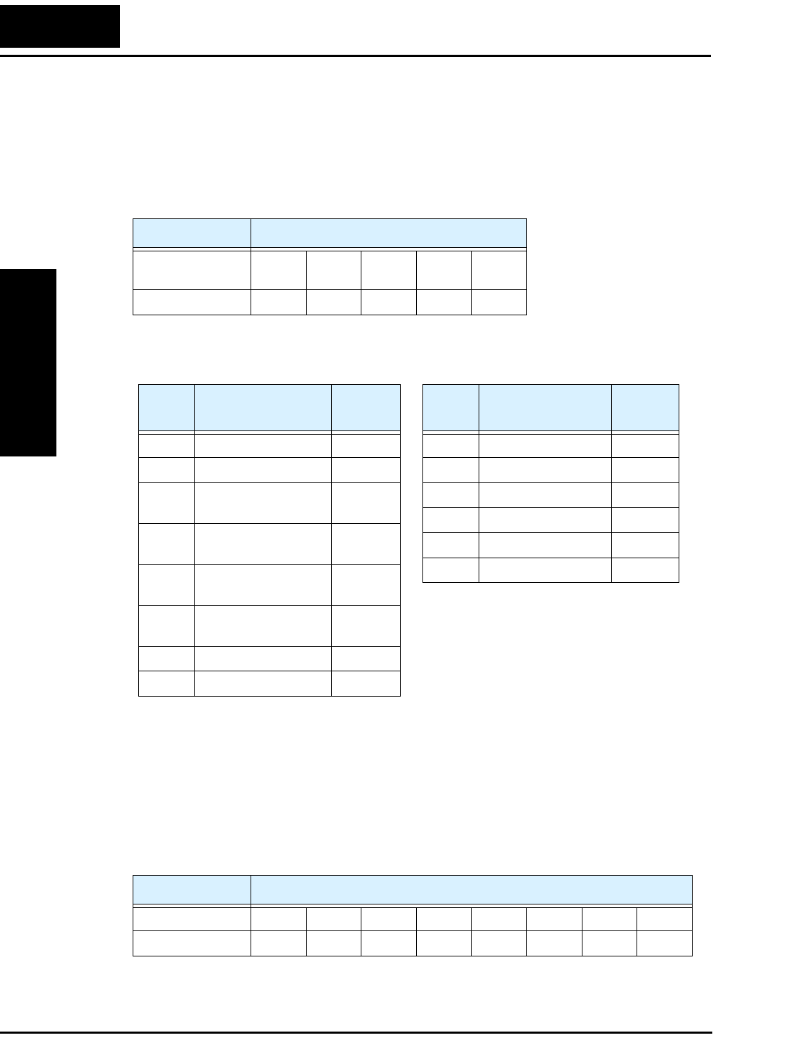
Network Protocol Reference
Appendix B
B–10
Explanation of function codes
Read Coil Status [01h]:
This function reads the status (ON/OFF) of selected coils. An example follows below.
• Read intelligent input terminals [1] to [5] of an inverter having a slave address “8.”
• This example assumes the intelligent input terminals have terminal states listed below.
• The data set in the response shows terminal states of coils 7 to 14.
• Data “17h = 00010111b” indicates the following assuming coil 7 is the LSB.
Item Data
Intelligent input
terminal
[1] [2] [3] [4] [5]
Coil Status ON ON ON OFF ON
Item Data
Coil Number 14 13 12 11 10 9 8 7
Coil Status OFF OFF OFF ON OFF ON ON ON
Query:
Note 1: Broadcasting is disabled.
Note 2: When 0 or more than 32 is
specified as a number of coils,
error code “03h” is returned.
Response:
Note 3: Data is transferred by the
specified number of data bytes
(data size).
No. Field Name Example
(Hex)
1 Slave address *1 08
2 Function code 01
3 Coil start number
(high order)
00
4 Coil start number
(low order)
07
5 Number of coils
(high order) *2
00
6 Number of coils (low
order) *2
06
7 CRC-16 (high order) 0D
8 CRC-16 (low order) 50
No. Field Name Example
(Hex)
1 Slave address 08
2 Function code 01
3 Data size (in bytes) 01
4 Coil data *3 17
5 CRC-16 (high order) 12
6 CRC-16 (low order) 1A

L2002 Inverter
Appendix B
B–11
• When a read coil is outside the defined coils, the final coil data to be transmitted
contains “0“as the status of the coil outside the range.
• When the Read Coil Status command cannot be executed normally, see the exception
response.
Read Holding Register [03h]:
This function reads the contents of the specified number of consecutive holding registers
(of specified register addresses). An example follows below.
• Reading previous three trip factors from an inverter having a slave address “5”
• This example assumes the previous three trip factors are as follows:
L2002 Command D081 (N) D082 (N-1) D083 (N-2)
Coil Number 0019h 001Ah 0018h
Trip factor Over-voltage (E07) Under-voltage (E09) No trip
Query:
Note 1: Broadcasting is disabled.
.Response:
Note 2: Data is transferred by the
specified number of data bytes
(data size). In this case, 6 bytes
are used to return the content
of three holding registers.
No. Field Name Example
(Hex)
1 Slave address *1 05
2 Function code 03
3 Register start number
(high order)
00
4 Register start number
(low order)
19
5 Number of holding
registers (high order)
00
6 Number of holding
registers (low order)
03
7 CRC-16 (high order) D5
8 CRC-16 (low order) 88
No. Field Name Example
(Hex)
1 Slave address 05
2 Function code 03
3 Data size (in bytes) *2 06
4 Register start number
(high order)
00
5 Register start number
(low order)
07
6 Register start number + 1
(high order)
00
7 Register start number +1
(low order)
09
8 Register start number + 2
(high order)
00
9 Register start number +2
(low order)
FF
10 CRC-16 (high order) 36
11 CRC-16 (low order) 37
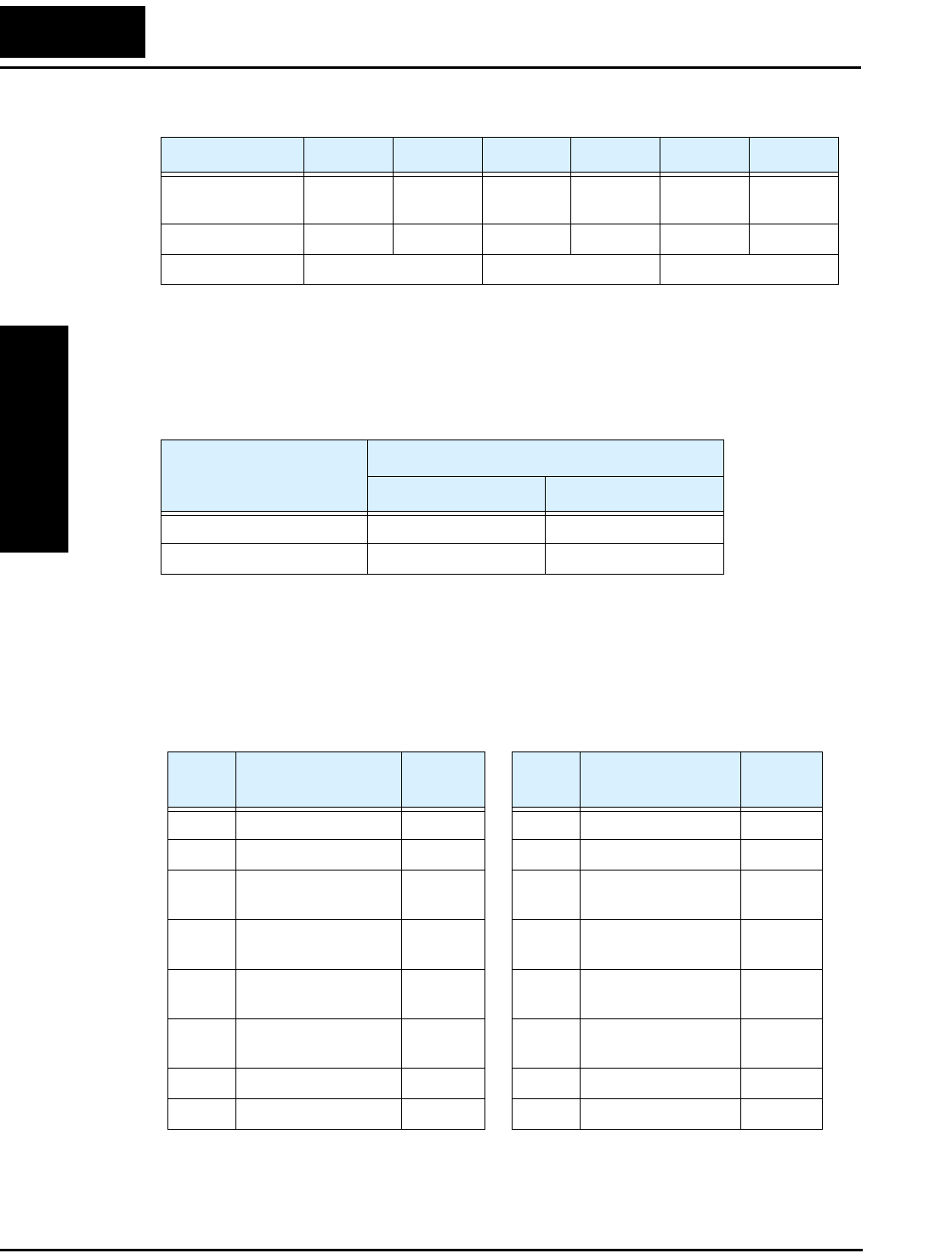
Network Protocol Reference
Appendix B
B–12
The data set in the response is as follows:
When the Read Coil Status command cannot be executed normally, refer to the
exception response.
Write in Coil [05h]:
This function writes data in a single coil. Coil status changes are as follows:
An example follows (note that to command the inverter, set A002=03):
• Sending a RUN command to an inverter having slave address “10”
• This example writes in coil number “1.”
Response Buffer 4 5 6 7 8 9
Coil Number + 0 (high
order)
+ 0 (low
order)
+ 1 (high
order)
+ 1 (low
order)
+ 2 (high
order)
+ 2 (low
order)
Coil Status 00h 07h 00h 09h 00h FFh
Trip data Over-voltage trip Under-voltage trip No trip
Data
Coil Status
OFF to ON ON to OFF
Change data (high order) FFh 00h
Change data (low order) 00h 00h
Query:
Note 1: No response is made for a
broadcasting query.
Response:
No. Field Name Example
(Hex)
1 Slave address *1 0A
2 Function code 05
3 Coil start number
(high order)
00
4 Coil start number
(low order)
01
5 Change data
(high order)
FF
6 Change data
(low order)
00
7 CRC-16 (high order) DC
8 CRC-16 (low order) 81
No. Field Name Example
(Hex)
1 Slave address 0A
2 Function code 05
3 Coil start number
(high order)
00
4 Coil start number
(low order)
01
5 Change data
(high order)
FF
6 Change data
(low order)
00
7 CRC-16 (high order) DC
8 CRC-16 (low order) 81

L2002 Inverter
Appendix B
B–13
When writing in a selected coil fails, see the exception response.
Write in Holding Register [06h]:
This function writes data in a specified holding register. An example follows:
• Write “50Hz” as the first Multi-speed 0 (A020) in an inverter having slave address
“5.”
• This example uses change data “500(1F4h)” to set “50Hz” as the data resolution of the
register “003Ah” holding the first Multi-speed 0 (A020) is 0.1Hz
When writing in a selected holding register fails, see the exception response.
Query:
Note 1: No response is made for a
broadcasting query.
Response:
No. Field Name Example
(Hex)
1 Slave address *1 05
2 Function code 06
3 Register start number
(high order)
00
4 Register start number
(low order)
3A
5 Change data
(high order)
01
6 Change data
(low order)
F4
7 CRC-16 (high order) A8
8 CRC-16 (low order) 54
No. Field Name Example
(Hex)
1 Slave address 05
2 Function code 06
3 Register start
number (high order)
00
4 Register start
number (low order)
3A
5 Change data
(high order)
01
6 Change data
(low order)
F4
7 CRC-16 (high order) A8
8 CRC-16 (low order) 54
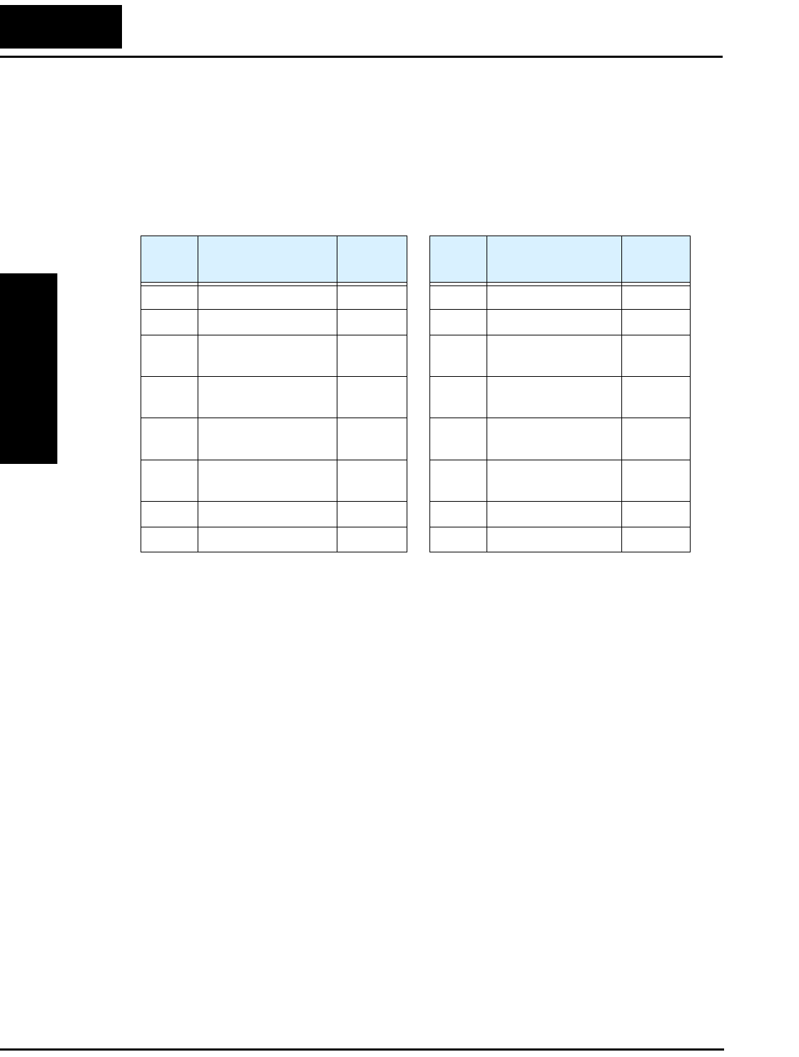
Network Protocol Reference
Appendix B
B–14
Loopback Test [08h]:
This function checks a master-slave transmission using any test data. An example
follows:
• Send test data to an inverter having slave address “1” and receiving the test data from
the inverter (as a loopback test).
The test subcode is for echo (00h,00h) only and not available to the other commands.
Query:
Note 1: Broadcasting is disabled.
Response:
No. Field Name Example
(Hex)
1 Slave address *1 01
2 Function code 08
3 Test subcode
(high order)
00
4 Test subcode
(low order)
00
5Data
(high order)
Any
6Data
(low order)
Any
7 CRC-16 (high order) CRC
8 CRC-16 (low order) CRC
No. Field Name Example
(Hex)
1 Slave address 01
2 Function code 08
3 Test subcode
(high order)
00
4 Test subcode
(low order)
00
5Data
(high order)
Any
6Data
(low order)
Any
7 CRC-16 (high order) CRC
8 CRC-16 (low order) CRC
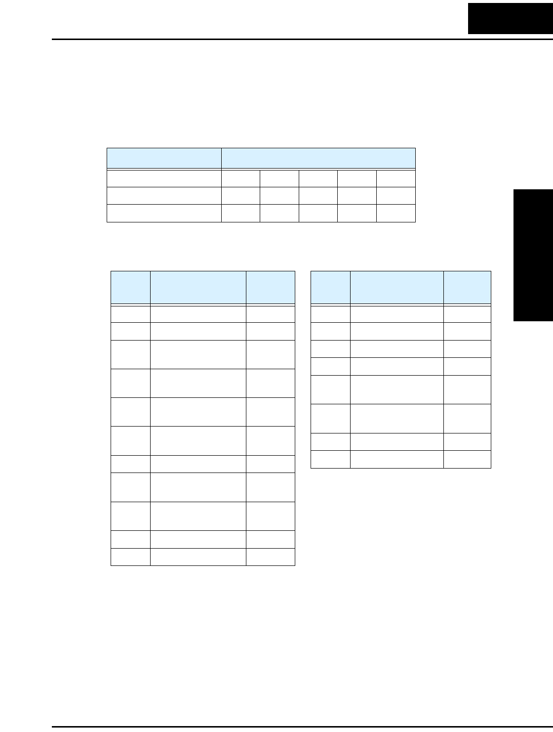
L2002 Inverter
Appendix B
B–15
Write in Coils [0Fh]:
This function writes data in consecutive coils. An example follows:
• Change the state of intelligent input terminal [1] to [5] of an inverter having a slave
address “5.”
• This example assumes the intelligent input terminals have terminal states listed below.
Item Data
Intelligent input terminal [1] [2] [3] [4] [5]
Coil number 7 8 9 10 11
Terminal status ON ON ON OFF ON
Query:
Note 1: Broadcasting is disabled.
Note 2: The change data is a set of
high-order data and low-order
data. So when the size (in
bytes) of data to be changed is
an odd number, add “1” to the
data size (in bytes) to make it
an even number.
Response:
No. Field Name Example
(Hex)
1 Slave address *1 05
2 Function code 0F
3 Coil start number
(high order)
00
4 Coil start number
(low order)
07
5 Number of coils
(high order)
00
6 Number of coils (low
order)
06
7 Byte number *2 02
8 Change data
(high order) *2
17
9 Change data
(low order) *2
00
10 CRC-16 (high order) DA
11 CRC-16 (low order) EF
No. Field Name Example
(Hex)
1 Slave address 05
2 Function code 0F
3 Data size (in bytes) 00
4 Coil data *3 07
5 Number of coils
(high order)
00
6 Number of coils
(low order)
06
7 CRC-16 (high order) 65
8 CRC-16 (low order) 8C
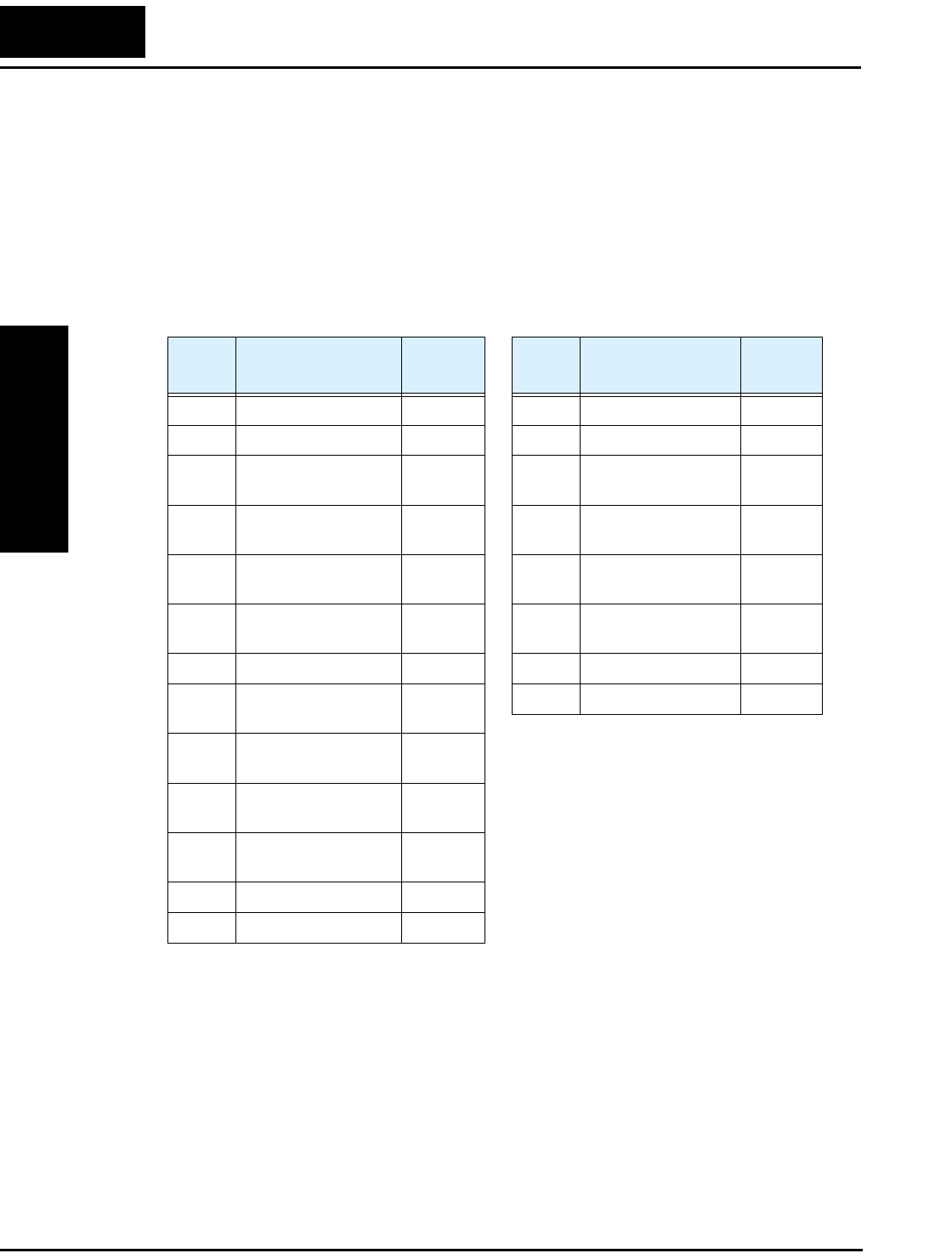
Network Protocol Reference
Appendix B
B–16
Writing in Holding Registers [10h]:
This function writes data in consecutive holding registers. An example follows:
• Write “3000 seconds” as the first acceleration time 1 (F002) in an inverter having a
slave address “1.”
• This example uses change data “300000(493E0h)” to set “3000 seconds” as the data
resolution of the registers “0024h” and “0025h” holding the first acceleration time 1
(F002) is 0.01 second.
When writing in selected holding registers fails, see the exception response.
Query:
Note 1: Broadcasting is disabled.
Note 2: This is not the number of
holding registers. Specify the
number of bytes of data to be
changed.
Response:
No. Field Name Example
(Hex)
1 Slave address *1 01
2 Function code 10
3 Start address (high
order)
00
4 Start address (low
order)
24
5 Number of holding
registers (high order)
00
6 Number of holding
registers (low order)
02
7 Byte number *2 04
8 Change data 1
(high order)
00
9 Change data 1
(low order)
04
10 Change data 2
(high order)
93
11 Change data 2
(low order)
E0
12 CRC-16 (high order) DC
13 CRC-16 (low order) FD
No. Field Name Example
(Hex)
1 Slave address 01
2 Function code 10
3 Start address (high
order)
00
4 Start address (low
order)
24
5 Number of holding
registers (high order)
00
6 Number of holding
registers (low order)
02
7 CRC-16 (high order) 01
8 CRC-16 (low order) C3
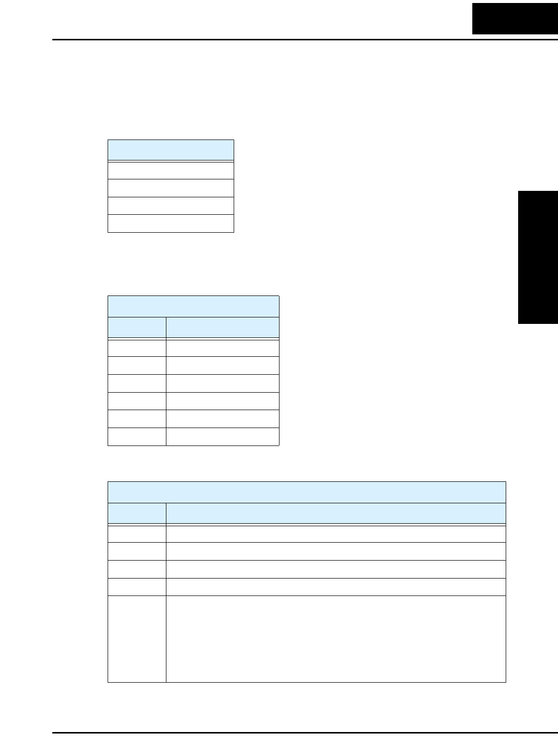
L2002 Inverter
Appendix B
B–17
Exception Response:
When sending a query (excluding a broadcasting query) to an inverter, the master always
requests a response from the inverter. Usually, the inverter returns a response according
to the query. However, when finding an error in the query, the inverter returns an excep-
tion response. The exception response consists of the fields shown below.
The content of each field is explained below. The function code of the exception
response is the sum of the function code of the query and 80h. The exception code
indicates the factor of the exception response.
Field Configuration
Slave address
Function code
Exception code
CRC–16
Function Code
Query Exception Response
0 1 h 8 1 h
0 3 h 8 3 h
0 5 h 8 5 h
0 6 h 8 6 h
0 F h 8 F h
1 0 h 9 0 h
Exception Code
Code Description
0 1 h The specified function is not supported.
0 2 h The specified address is not found.
0 3 h The format of the specified data is not acceptable.
2 1 h The data to be written in a holding register is outside the inverter
2 2 h These specified functions are not available to the inverter:
•Function to change the content of a register that cannot be changed while the
inverter is in service
•Function to submit an ENTER command during running (UV)
•Function to write in a register during tripping (UV)
•Function to write in a read-only register (or coil)

Network Protocol Reference
Appendix B
B–18
Store New Register Data (ENTER command)
After being written in a selected holding register by the Write in Holding Register
command (06h) or in selected holding registers by the Write in Holding Registers
command (10h), new data is temporary and still outside the storage element of the
inverter. If power to the inverter is shut off, this new data is lost and the previous data
returns. The ENTER command is used to store this new data in the storage element of
the inverter. Follow the instructions below to submit the ENTER command.
Submitting an ENTER Command:
• Write any data in all memory (of a holding register at 0900h) by the Write in Holding
Register command [06h].
NOTE: The ENTER command takes much time to run. You can check its progress by
monitoring the Data Writing signal (of a coil at 001Ah).
NOTE: The service life of the storage element of the inverter is limited (to about
100,000 write operations). Frequent use of the ENTER command may shorten its service
life.
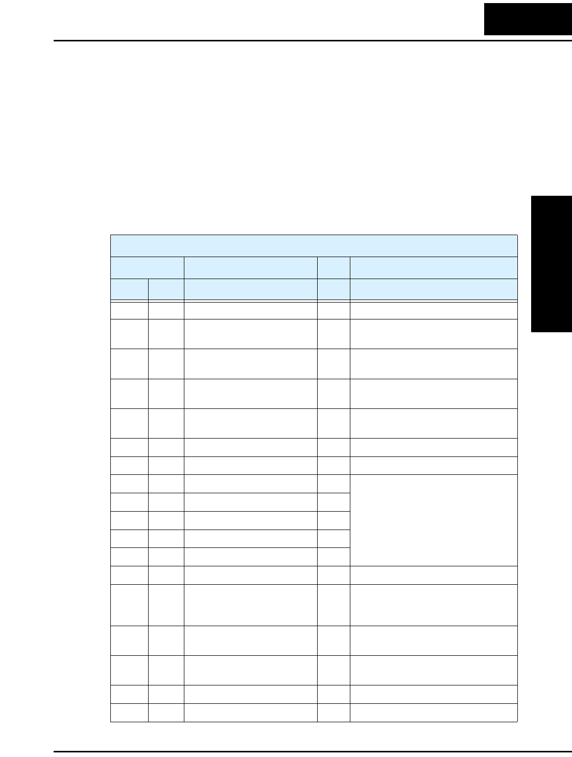
L2002 Inverter
Appendix B
B–19
ModBus Data Listing
ModBus Coil List
The following tables list the primary coils for the inverter interface to the network. The
table legend is given below.
•Coil Number - The network register address offset for the coil, in hex and decimal.
Actual network address is 30001 + offset. The coil data is a single bit (binary) value.
•Name - The functional name of the coil
•R/W - The read-only (R) or read-write (R/W) access permitted to the inverter data
•Description - The meaning of each of the states of the coils
List of Coil Numbers
Coil Number Name R/W Description
hex dec.
0000h 00000 (Reserved) R —
0001h 00001 Run command R/W 0 .... Stop
1 .... Run (enabled when A003=03)
0002h 00002 FW/REV command R/W 0 .... REV
1 .... FW (enabled when A003=03)
0003h 00003 External trip (EXT) R/W 0 .... No trip event
1 .... Trip occurred
0004h 00004 Trip reset (RS) R/W 0 .... No reset condition
1 .... Reset
0005h 00005 (Reserved) R —
0006h 00006 (Reserved) R —
0007h 00007 Intelligent input terminal 1 R/W 0 .... OFF *1
1 .... ON
0008h 00008 Intelligent input terminal 2 R/W
0009h 00009 Intelligent input terminal 3 R/W
000Ah 00010 Intelligent input terminal 4 R/W
000Bh 00011 Intelligent input terminal 5 R/W
000Dh 00013 (Not used) — —
000Eh 00014 Run/Stop status R 0 .... Stop (corresponds to D003
monitor)
1 .... Run
000Fh 00015 FW/REV status R 0 .... FW
1 .... RV
0010h 00016 Inverter ready R 0 .... Not ready
1 .... Ready
0011h 00017 (Reserved) R —
0012h 00018 (Reserved) R —
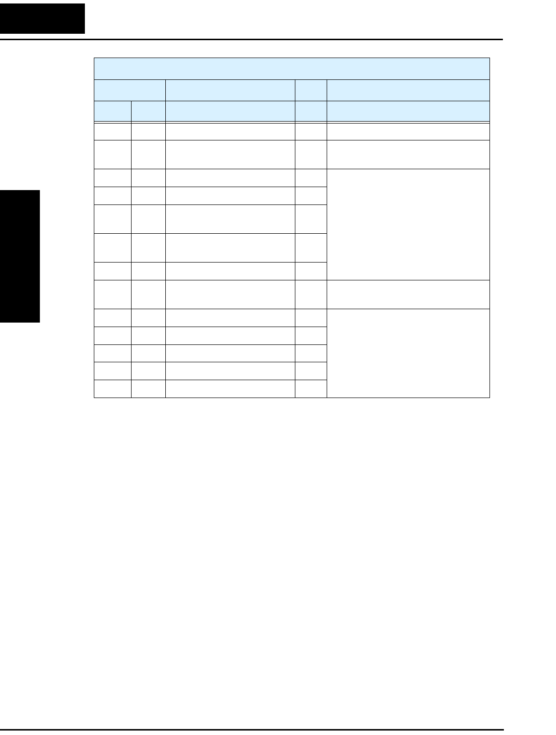
ModBus Data Listing
Appendix B
B–20
Note 1: ON usually when either the control circuit terminal board or a coil is ON.
Among intelligent input terminals, the control circuit terminal board is a high-
priority terminal. If the master cannot reset the coil ON status due to a trans-
mission line break, turn ON and OFF the control circuit terminal board to
make the coil OFF status.
Note 2: The content of a transmission error is held until the error is reset. (The error
can be reset while the inverter is running.)
0013h 00019 (Reserved) R —
0014h 00020 Alarm signal R 0..... Normal
1..... Trip
0015h 00021 PID deviation signal R 0..... OFF
1..... ON
0016h 00022 Overload signal R
0017h 00023 Frequency arrival signal
(set frequency or above)
R
0018h 00024 Frequency arrival signal
(at constant speed)
R
0019h 00025 Run Mode signal R
001Ah 00026 Data writing R 0..... Normal status
1..... Writing
001Bh 00027 CRC error R 0..... No error *2
1..... Error
001Ch 00028 Overrun error R
001Dh 00029 Framing error R
001Eh 00030 Parity error R
001Fh 00031 Check sum error R
List of Coil Numbers
Coil Number Name R/W Description
hex dec.
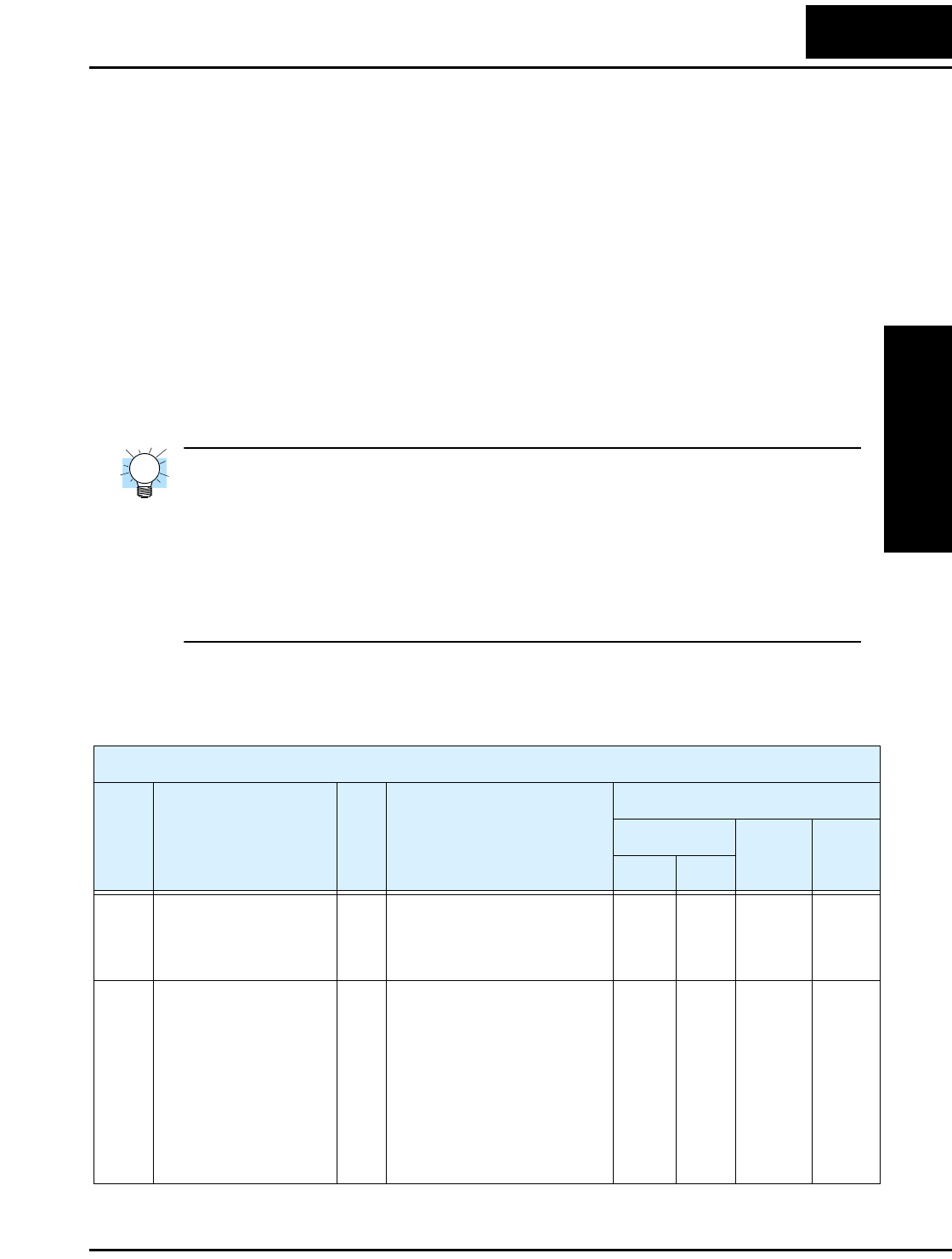
L2002 Inverter
Appendix B
B–21
ModBus Holding Registers
The following tables list the holding registers for the inverter interface to the network.
The table legend is given below.
•Function Code - The inverter’s reference code for the parameter or function (same as
inverter keypad display)
•Name - The standard functional name of the parameter or function for the inverter
•R/W - The read-only or read-write access permitted to the data in the inverter
•Description - How the parameter or setting works (same as Chapter 3 description).
•Register - The network register address offset for the value, in hex and decimal.
Actual network address is 40001 + offset. Some values have a high-byte and low-byte
address.
•Range - The numerical range for the network value that is sent and/or received
TIP: The network values are binary integers. Since these values cannot have an
embedded decimal point, for many parameters it represents the actual value (in engineer-
ing units) multiplied by a factor of 10 or 100. Network communications must use the
listed range for network data. The inverter automatically divides received values by the
appropriate factor in order to establish the decimal point for internal use. Likewise, the
network host computer must apply the same factor when it needs to work in engineering
units. However, when sending data to the inverter, the network host computer must scale
values to the integer range listed for network communications.
• Resolution - This is the quantity represented by the LSB of the network value, in
engineering units. When the network data range is greater than the inverter’s internal
data range, this 1-bit resolution will be fractional.
List of Holding Registers
Func.
Code Name R/W Description
Network Data
Reg.ister
Range Res.
hex dec.
— Output frequency
command
Inverter output frequency (set
A001=03 to enable this
network register),
range is 0.0 to 400.0 Hz
0002h 00002 0 to
4000
0.1 Hz
— Inverter status R/W 00 ...Initial status
01 ...(Reserved)
02 ...Stop Mode
03 ...Run Mode
04 ...Free-run stop (FRS)
05 ...Jogging
06 ...DC braking
07 ...Retry
08 ...Trip alarm
09 ...Under-voltage
0003h 00003 0 to 9 —

ModBus Data Listing
Appendix B
B–22
— Process Variable (PV) RW PID loop PV value from the
network (set A076=02 to
enable this setting), range is
0.0 to 100.0%
0005h 00005 0 to
1000
0.1%
D001 Output frequency
monitor
R Real-time display of output
frequency to motor, from
0.0 to 400.0 Hz
1002h 04098 0 to
4000
0.1 Hz
D002 Output current monitor
*1
R Filtered display of output
current to motor (100 ms
internal filter time constant),
range is 0 to 200% of inverter
rated current
1003h 04099 0 to
2000
0.1%
D003 Rotation direction
monitor
R Three different indications:
00 ...Stop
01 ...Forward
02 ...Reverse
1004h 04100 0, 1, 2 —
D004
(high)
Process variable (PV),
PID feedback monitor
R Displays the scaled PID
process variable (feedback)
value (A075 is scale factor),
range is 0.00 to 99900
1005h 04101 0 to
999900
0.00%
times
const.
D004
(low)
R 1006h 04102
D005 Intelligent input
terminal status
R Displays the state of the intel-
ligent input terminals [x],
Bit 0 = [1] to Bit 4 = [5]
1007h 04103 0 to 31 —
D006 Intelligent output
terminal status
R Displays the state of the intel-
ligent output terminals [x],
Bit 0 = [11], Bit 1 = [12],
Bit 2 = [AL]
1008h 04104 0 to 7 —
D007
(high)
Scaled output frequency
monitor
R Displays the output frequency
scaled by the constant in
B086. Decimal point indicates
range:
0.00 to 99999
1009h 04105 0 to
999999
0.01 Hz
times
const.
D007
(low)
R 100Ah 04106
D013 Output voltage monitor R Voltage of output to motor,
range is 0.00 to 200.00%
100Ch 04108 0 to
20000
0.01%
D016
(high)
Cumulative operation
RUN time monitor
R Displays total time the
inverter has been in RUN
mode in hours.
Range is 0 to 999000
100Eh 04110 0 to
999999
1 hour
D016
(low)
R 100Fh 04111
D017
(high)
Cumulative power-on
time monitor
R Displays total time the
inverter has been in RUN
mode in hours.
Range is 0 to 999000
1010h 04112 0 to
999999
1 hour
D017
(low)
R 1011h 04113
List of Holding Registers
Func.
Code Name R/W Description
Network Data
Reg.ister
Range Res.
hex dec.
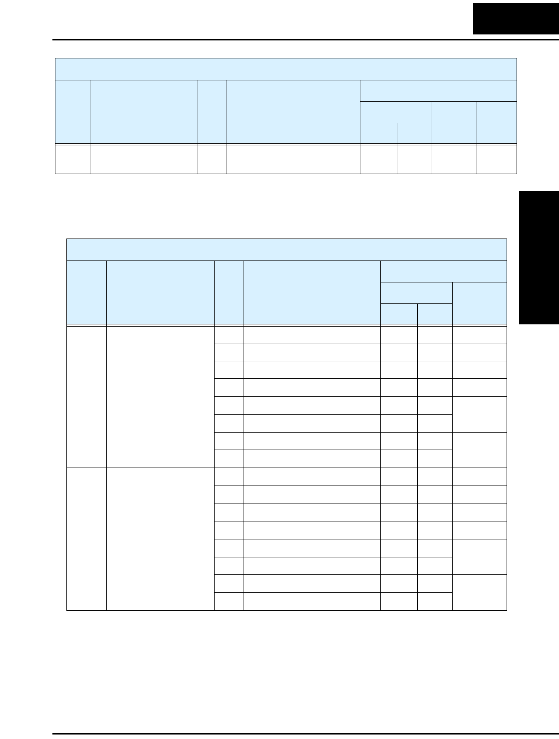
L2002 Inverter
Appendix B
B–23
Note 1: Assume that the inverter current rating is 1000 (for D002).
The following table lists holding registers for the “D” Group Monitor Functions.
D080 Trip counter R Number of trip events,
range is 0 to 65535
0011h 00024 0 to
65535
1 trip
event
List of Holding Registers
Func.
Code Name R/W Description
Network Data
Reg.ister
Range Res.
hex dec.
Holding Registers, “D” Group Monitor Functions
Func.
Code Name R/W Description
Network Data
Register
Res.
hex dec.
D081 Trip monitor 1
R Trip monitor 1: factor code 0012h 00018 —
R Frequency 0014h 00020 0.1 Hz
R Current 0016h 00022 0.1 %
R Voltage 0017h 00023 0.1 V
R Run time (high) 0018h 00024 1. h
R Run time (low) 0019h 00025
R ON time (high) 001Ah 00026 1. h
R ON time (low) 001Bh 00027
D082 Trip monitor 2
R Trip monitor 1: factor code 001Ch 00028 —
R Frequency 001Eh 00030 0.1 Hz
R Current 0020h 00032 0.1 %
R Voltage 0021h 00033 0.1 V
R Run time (high) 0022h 00034 1. h
R Run time (low) 0023h 00035
R ON time (high) 0024h 00036 1. h
R ON time (low) 0025h 00037
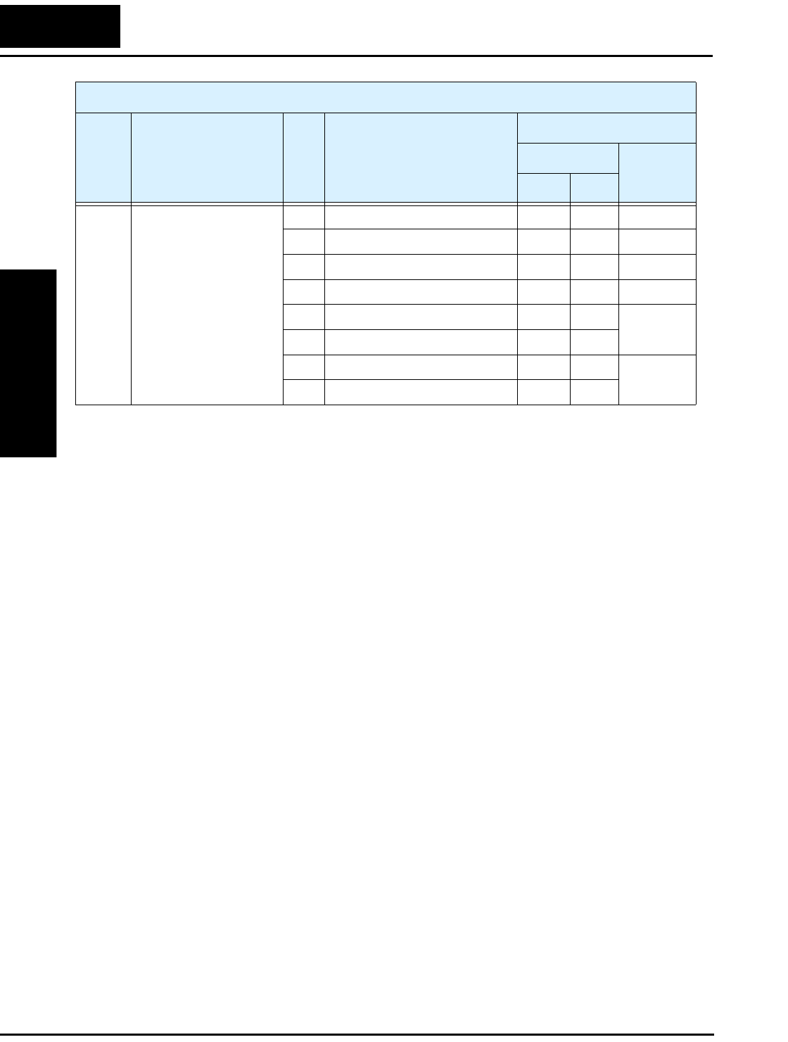
ModBus Data Listing
Appendix B
B–24
D083 Trip monitor 3
R Trip monitor 1: factor code 0026h 00272 —
R Frequency 0028h 00273 0.1 Hz
R Current 002Ah 00274 0.1 %
R Voltage 002Bh 00275 0.1 V
R Run time (high) 002Ch 00276 1. h
R Run time (low) 002Dh 00277
R ON time (high) 002Eh 00278 1. h
R ON time (low) 002Fh 00279
Holding Registers, “D” Group Monitor Functions
Func.
Code Name R/W Description
Network Data
Register
Res.
hex dec.

L2002 Inverter
Appendix B
B–25
The table below lists the holding registers for the “F” Group Main Profile Parameters.
Note 1: When the value is 10000 (100.0 seconds), a value in the second decimal place
is ignored.
Holding Registers, “F” Group Main Profile Parameters
Func.
Code Name R/W Description
Network Data
Register
Range Res.
hex dec.
F002
(high)
Acceleration (1) time
setting *1
R/W Standard default acceleration,
range is 0.01 to 3000 sec.
1014h 04116 1 to
300000
0.01
sec
F002
(low)
R/W 1015h 04117
F202
(high)
Acceleration (1) time
setting, 2nd motor *1
R/W Standard default acceleration,
2nd motor,
range is 0.01 to 3000 sec.
1501h 05377 1 to
300000
0.01
sec
F202
(low)
R/W 1502h 05378
F003
(high)
Deceleration (1) time
setting *1
R/W Standard default deceleration,
range is
0.01 to 3000 sec.
1016h 04118 1 to
300000
0.01
sec
F003
(low)
R/W 1017h 04119
F203
(high)
Deceleration (1) time
setting, 2nd motor *1
R/W Standard default deceleration,
2nd motor,
range is 0.01 to 3000 sec.
1503h 05379 1 to
300000
0.01
sec
F203
(low)
R/W 1504h 05380
F004 Keypad Run key routing R/W Two options; select codes:
00 ...Forward
01 ...Reverse
1018h 04120 0, 1 —

ModBus Data Listing
Appendix B
B–26
The following table lists the holding registers for the “A” Group Standard Functions.
Holding Registers for “A” Group Standard Functions
Func.
Code Name R/W Description
Network Data
Register
Range Res.
hex dec.
A001 Frequency source
setting
R/W Five options; select codes:
00... Keypad potentiometer
01... Control terminal
02... Function F001 setting
03... ModBus network input
10... Calculate function output
1019h 04121 0 to 3, 10 —
A002 Run command source
setting
R/W Three options; select codes:
01... Control terminal
02... Run key on keypad, or
digital operator
03... ModBus network input
101Ah 04122 1, 2, 3 —
A003 Base frequency setting R/W Settable from 30 Hz to the
maximum frequency
101Bh 04123 30 to
max. freq.
1 Hz
A203 Base frequency setting,
2nd motor
R/W Settable from 30 Hz to the
2nd maximum frequency
150Ch 05388 30 to
max. freq.
2
1 Hz
A004 Maximum frequency
setting
R/W Settable from the base
frequency up to 400 Hz
101Ch 04124 30 to 400 1 Hz
A204 Maximum frequency
setting, 2nd motor
R/W Settable from the 2nd base
frequency up to 400 Hz
150Dh 05389 30 to 400 1 Hz
A005 [AT] selection R/W Four options, select codes:
00... Select between [O] and
[OI] at [AT]
01... [O] + [OI] ([AT] input is
ignored)
02... Select between [O] and
keypad potentiometer
03... Select between [OI] and
keypad potentiometer
101Dh 04125 0, 1, 2, 3 —
A011 O–L input active range
start frequency
R/W The output frequency corre-
sponding to the analog input
range starting point,
range is 0.0 to 400.0
1020h 04128 0 to 4000 0.1 Hz
A012 O–L input active range
end frequency
R/W The output frequency corre-
sponding to the analog input
range ending point,
range is 0.0 to 400.0
1022h 04130 0 to 4000 0.1 Hz
A013 O–L input active range
start voltage
R/W The starting point (offset) for
the active analog input range,
range is 0. to 100
1023h 04131 0 to 100 1 %

L2002 Inverter
Appendix B
B–27
A014 O–L input active range
end voltage
R/W The ending point (offset) for
the active analog input range,
range is 0. to 100.
1024h 04132 0 to 100 1 %
A015 O–L input start
frequency enable
R/W Two options; select codes:
00... Use offset (A011 value)
01... Use 0 Hz
1025h 04133 0, 1 —
A016 External frequency
filter time constant
R/W Range n = 1 to 16, where n =
number of samples for avg.
Set = 17 to use 16-sample avg.
1026h 04134 1 to 17 1
sample
A020 Multi-speed 0 setting R/W Defines the first speed of a
multi-speed profile, range is
0.0 / start frequency to 400 Hz
A020 = Speed 0 (1st motor)
1029h 04137 0 / start
freq. to
4000
0.1 Hz
A220 Multi-speed 0 setting,
2nd motor
R/W Defines the first speed of a
multi-speed profile, range is
0.0 / start frequency to 400 Hz
A220 = Speed 0 (2nd motor)
150Fh 00059 0 / start
freq. to
4000
0.1 Hz
A021 Multi-speed 1 setting R/W
Defines 15 more speeds,
range is 0.0 / start frequency
to 400 Hz.
A021= Speed 1...
A035 = Speed 15
102Bh 04139 0 / start
freq. to
4000
0.1 Hz
A022 Multi-speed 2 setting R/W 102Dh 04141
A023 Multi-speed 3 setting R/W 102Fh 04143
A024 Multi-speed 4 setting R/W 1031h 04145
A025 Multi-speed 5 setting R/W 1033h 04147
A026 Multi-speed 6 setting R/W 1035h 04149
A027 Multi-speed 7 setting R/W 1037h 04151
A028 Multi-speed 8 setting R/W 1039h 04153
A029 Multi-speed 9 setting R/W 103Bh 04155
A030 Multi-speed 10 setting R/W 103Dh 04157
A031 Multi-speed 11 setting R/W 103Fh 04159
A032 Multi-speed 12 setting R/W 1041h 04161
A033 Multi-speed 13 setting R/W 1043h 04163
A034 Multi-speed 14 setting R/W 1045h 04165
A035 Multi-speed 15 setting R/W 1047h 04167
A038 Jog frequency setting R/W Defines limited speed for jog,
range is 0.00 / start frequency
to 9.99 Hz
1048h 04168 0 / start
freq. to
999
0.01 Hz
Holding Registers for “A” Group Standard Functions
Func.
Code Name R/W Description
Network Data
Register
Range Res.
hex dec.

ModBus Data Listing
Appendix B
B–28
A039 Jog stop mode R/W Define how end of jog stops
the motor; three options:
00... Free-run stop
01... Controlled deceleration
02... DC braking to stop
1049h 04169 0, 1, 2 —
A041 Torque boost select R/W Two options:
00... Manual torque boost
01... Automatic torque boost
104Ah 04170 0, 1 —
A241 Torque boost select, 2nd
motor
R/W 1510h 05392
A042 Manual torque boost
value
R/W Can boost starting torque
between 0 and 20% above
normal V/f curve,
range is 0.0 to 20.0%
104Bh 04171 0 to 200 0.1 %
A242 Manual torque boost
value, 2nd motor
R/W 1511h 05393
A043 Manual torque boost
frequency adjustment
R/W Sets the frequency of the V/f
breakpoint A in graph (top of
previous page) for torque
boost, range is 0.0 to 50.0%
104Ch 04172 0 to 500 0.1 %
A243 Manual torque boost
frequency adjustment,
2nd motor
R/W 1512h 05394
A044 V/f characteristic curve
selection
R/W Two available V/f curves;
two select codes:
00... Constant torque
01... Reduced torque
104Dh 04173 0, 1, 2 —
A244 V/f characteristic curve
selection, 2nd motor
R/W 1513h 05395
A045 V/f gain setting R/W Sets voltage gain of the
inverter, range is 20. to 100.%
104Eh 04174 20 to 100 1 %
A051 DC braking enable R/W Two options; select codes:
00... Disable
01... Enable
1051h 04177 0, 1 —
A052 DC braking frequency
setting
R/W The frequency at which DC
braking begins,
range is from the start
frequency (B082) to 60 Hz
1052h 04178 (B082 x
10) to 600
0.1 Hz
A053 DC braking wait time R/W The delay from the end of
controlled deceleration to start
of DC braking (motor free
runs until DC braking begins),
range is 0.0 to 5.0 sec.
1053h 04179 0, 1 —
A054 DC braking force for
deceleration
R/W Level of DC braking force,
settable from 0 to 100%
1054h 04180 0 to 100 1 %
A055 DC braking time for
deceleration
R/W Sets the duration for DC
braking, range is 0.0 to 60.0
seconds
1055h 04181 0 to 600 0.1 sec
Holding Registers for “A” Group Standard Functions
Func.
Code Name R/W Description
Network Data
Register
Range Res.
hex dec.

L2002 Inverter
Appendix B
B–29
A056 DC braking / edge or
level detection for [DB]
input
R/W Two options; select codes:
00... Edge detection
01... Level detection
1056h 04182 0, 1 —
A061 Frequency upper limit
setting
R/W Sets a limit on output
frequency less than the
maximum frequency (A004).
Range is from frequency
lower limit (A062) to
maximum frequency (A004).
0.0.. setting is disabled
>0.1 setting is enabled
105Ah 04186 (A062 x
10) to
(A004 x
10),
0=disable
>1=enabl
e
0.1 Hz
A261 Frequency upper limit
setting, 2nd motor
R/W 1517h 05399
A062 Frequency lower limit
setting
R/W Sets a limit on output
frequency greater than zero.
Range is start frequency
(B082) to frequency upper
limit (A061).
0.0.. setting is disabled
>0.1 setting is enabled
105Bh 04187 (B082 x
10) to
(A061 x
10),
0=disable
>1=enabl
e
0.1 Hz
A262 Frequency lower limit
setting, 2nd motor
R/W 1518h 05400
A063,
A065,
A067
Jump (center) frequency
setting
R/W Up to 3 output frequencies
can be defined for the output
to jump past to avoid motor
resonances (center frequency)
Range is 0.0 to 400.0 Hz
105Dh
1060h
1063h
04189
04192
04195
0 to 4000 0.1 Hz
A064,
A066,
A068
Jump (hysteresis)
frequency width setting
R/W Defines the distance from the
center frequency at which the
jump around occurs
Range is 0.0 to 10.0 Hz
105Eh
1061h
1064h
04190
04193
04196
0 to 100 0.1 Hz
A071 PID Enable R/W Enables PID function,
two option codes:
00... PID Disable
01... PID Enable
1068h 04200 0, 1 —
A072 PID proportional gain R/W Proportional gain has a range
of 0.2 to 5.0
1069h 04201 2 to 50 0.1
A073 PID integral time
constant
R/W Integral time constant has a
range of 0.0 to 150 seconds
106Ah 04202 0 to 1500 0.1 sec
A074 PID derivative time
constant
R/W Derivative time constant has a
range of 0.0 to 100 seconds
106Bh 04203 0 to 1000 0.1 sec
A075 PV scale conversion R/W Process Variable (PV) scale
factor (multiplier), range of
0.01 to 99.99
106Ch 04204 1 to 9999 0.01
Holding Registers for “A” Group Standard Functions
Func.
Code Name R/W Description
Network Data
Register
Range Res.
hex dec.

ModBus Data Listing
Appendix B
B–30
A076 PV source setting R/W Selects source of Process
Variable (PV), option codes:
00... [OI] terminal (current in)
01... [O] terminal (voltage in)
02... Network
03... Calculate function output
106Dh 04205 0, 1, 2, 3 —
A077 Reverse PID action R/W Two option codes:
00... PID input = SP – PV
01... PID input = –(SP – PV)
106Eh 04206 0, 1 —
A078 PID output limit R/W Sets the limit of PID output as
percent of full scale,
range is 0.0 to 100.0%
106Fh 04207 0 to 1000 0.1 %
A081 AVR function select R/W Automatic (output) voltage
regulation, selects from three
type of AVR functions, three
option codes:
00... AVR enabled
01... AVR disabled
02... AVR enabled except
during deceleration
1070h 04208 0, 1, 2 —
A082 AVR voltage select R/W 200V class inverter settings:
00... 200
01... 215
02... 220
03... 230
04... 240
400V class inverter settings:
00... 380
01... 400
02... 415
03... 440
04... 460
05... 480
1071h 04209 0 to 5 —
A092
(high)
Acceleration (2) time
setting
R/W Duration of 2nd segment of
acceleration, range is:
0.01 to 3000 sec.
1074h 04212 1 to
300000
*1
0.1 sec
A092
(low)
R/W 1075h 04213
A292
(high)
Acceleration (2) time
setting, (2nd motor)
R/W Duration of 2nd segment of
acceleration, 2nd motor,
range is: 0.01 to 3000 sec
1518h 05400 1 to
300000
*1
0.1 sec
A292
(low)
R/W 1519h 05401
Holding Registers for “A” Group Standard Functions
Func.
Code Name R/W Description
Network Data
Register
Range Res.
hex dec.

L2002 Inverter
Appendix B
B–31
A093
(high)
Deceleration (2) time
setting
R/W Duration of 2nd segment of
deceleration, range is:
0.01 to 3000 sec.
1076h 04214 1 to
300000
*1
0.1 sec
A093
(low)
R/W 1077h 04215
A293
(high)
Deceleration (2) time
setting, (2nd motor)
R/W Duration of 2nd segment of
deceleration, range is:
0.01 to 3000 sec.
151Ah 00122 1 to
300000
*1
0.1 sec
A293
(low)
R/W 151Bh 00123
A094 Select method to switch
to Acc2/Dec2 profile
R/W Two options for switching
from 1st to 2nd accel/decel:
00... 2CH input from terminal
01... transition frequency
1078h 04216 0, 1 —
A294 Select method to switch
to Acc2/Dec2 profile,
2nd motor
R/W 151Ch 05404
A095 Acc1 to Acc2 frequency
transition point
R/W Output frequency at which
Accel1 switches to Accel2,
range is 0.0 to 400.0 Hz
107Ah 04218 0 to 4000 0.1 Hz
A295 Acc1 to Acc2 frequency
transition point, 2nd
motor
R/W 151Eh 05406
A096 Dec1 to Dec2 frequency
transition point
R/W Output frequency at which
Decel1 switches to Decel2,
range is 0.0 to 400.0 Hz
107Ch 04220 0 to 4000 0.1 Hz
A296 Dec1 to Dec2 frequency
transition point, 2nd
motor
R/W 1520h 05408
A097 Acceleration curve
selection
R/W Set the characteristic curve of
Acc1 and Acc2, two options:
00... linear
01... S-curve
107Dh 04221 0, 1 —
A098 Deceleration curve
selection
R/W Set the characteristic curve of
Acc1 and Acc2, two options:
00... linear
01... S-curve
107Eh 04222 0, 1 —
A101 [OI]–[L] input active
range start frequency
R/W The output frequency corre-
sponding to the current input
range starting point.
Range is 0.00 to 400.0 Hz
1080h 04224 0 to 4000 0.1 Hz
A102 [OI]–[L] input active
range end frequency
R/W The output frequency corre-
sponding to the current input
range ending point.
Range is 0.00 to 400.0 Hz
1082h 04226 0 to 4000 0.1 Hz
Holding Registers for “A” Group Standard Functions
Func.
Code Name R/W Description
Network Data
Register
Range Res.
hex dec.

ModBus Data Listing
Appendix B
B–32
A103 [OI]–[L] input active
range start current
R/W The starting point for the
current input range.
Range is 0. to 100.%
1083h 04227 0 to 100 1 %
A104 [OI]–[L] input active
range end current
R/W The ending point for the
current input range.
Range is 0. to 100.%
1084h 04228 0 to 100 1 %
A105 [OI]–[L] input start
frequency enable
R/W Two options:
00... Use A101 start value
01... Use 0Hz
1085h 04229 0, 1 —
A141 A input select for calcu-
late function
R/W Five options:
00... Digital operator
01... Keypad potentiometer
02... [O] input
03... [OI] input
04... Network variable
108Eh 04238 0 to 4 —
A142 B input select for calcu-
late function
R/W Five options:
00... Digital operator
01... Keypad potentiometer
02... [O] input
03... [OI] input
04... Network variable
108Fh 04239 0 to 4 —
A143 Calculation symbol R/W Calculates a value based on
the A input source (A141
selects) and the B input source
(A142 selects). Three options:
00... ADD (A input + B
input)
01... SUB (A input – B input)
02... MUL (A input x B input)
1090h 04240 0 1, 2 —
A145 ADD frequency R/W An offset value that is applied
to the output frequency when
the [ADD] terminal is ON.
Range is 0.0 to 400.0 Hz
1091h 04241 0 to 4000 0.1 Hz
A146 ADD direction select R/W Two options:
00... Plus (adds A145 value to
the output frequency setting)
01... Minus (subtracts A145
value from the output
frequency setting)
1093h 04243 0, 1 —
A151 Pot. input active range
start frequency
R/W The output frequency corre-
sponding to the potentiometer
range starting point,
range is 0.0 to 400.0
1095h 4245 0 to 4000 0.1 Hz
Holding Registers for “A” Group Standard Functions
Func.
Code Name R/W Description
Network Data
Register
Range Res.
hex dec.

L2002 Inverter
Appendix B
B–33
Note 1: When the value is 10000 (100.0 seconds), a value in the second decimal place
is ignored (for A092/A292 and A093/A293).
A152 Pot. input active range
end frequency
R/W The output frequency corre-
sponding to the potentiometer
range ending point,
range is 0.0 to 400.0
1097h 4247 0 to 4000 0.1 Hz
A153 Pot. input active range
start current
R/W The output frequency corre-
sponding to the potentiometer
range starting point,
range is 0 to 100
1098h 4248 0 to 100 1%
A154 Pot. input active range
end current
R/W The output frequency corre-
sponding to the potentiometer
range ending point,
range is 0 to 100
1099h 4249 0 to 100 1%
A155 Pot. input start
frequency enable
R/W Two options:
00... Disable
01... Enable
109Ah 4250 0, 1 —
Holding Registers for “A” Group Standard Functions
Func.
Code Name R/W Description
Network Data
Register
Range Res.
hex dec.

ModBus Data Listing
Appendix B
B–34
The following table lists the holding registers for the “B” Group Fine Tuning Functions.
“B” Group Fine Tuning Functions
Func.
Code Name R/W Description
Network Data
Register
Range Res.
hex dec.
B001 Selection of automatic
restart mode
R/W Select inverter restart method,
four option codes:
00... Alarm output after trip,
no automatic restart
01... Restart at 0Hz
02... Resume operation after
frequency matching
03... Resume previous freq.
after freq. matching, then
decelerate to stop and display
trip info.
10A5h 04261 0, 1, 2, 3 —
B002 Allowable under-
voltage power failure
time
R/W The amount of time a power
input under-voltage can occur
without tripping the power
failure alarm. Range is 0.3 to
25 sec. If under-voltage exists
longer than this time, the
inverter trips, even if the
restart mode is selected.
10A6h 04262 3 to 250 0.1 sec
B003 Retry wait time before
motor restart
R/W Time delay after under-
voltage condition goes away,
before the inverter runs motor
again.
Range is 0.3 to 100 seconds.
10A7h 04263 3 to
1000
0.1 sec
B004 Instantaneous power
failure / under-voltage
trip alarm enable
R/W Two option codes:
00... Disable
01... Enable
10A8h 04264 0, 1 —
B005 Number of restarts on
power failure / under-
voltage trip events
R/W Two option codes:
00... Restart 16 times
01... Always restart
10A9h 04265 0, 1 —
B012 Level of electronic
thermal setting
R/W Set a level between 20% and
120% for the rated inverter
current
10AD
h
04269 2000 to
12000
0.01%
B212 Level of electronic
thermal setting, 2nd
motor
R/W 1526h 05414
B013 Electronic thermal
characteristic
R/W Select from two curves,
option codes: *1
00... Reduced torque 1
01... Constant torque
02... Reduced torque 2
10AEh 04270 0, 1, 2 —
B213 Electronic thermal
characteristic, 2nd
motor
R/W 1527h 05415

L2002 Inverter
Appendix B
B–35
B021 Overload restriction
operation mode
R/W Select the operating mode
during overload conditions,
three options, option codes:
00... Disabled
01... Enabled for acceleration
and constant speed
02... Enabled for constant
speed only
10B5h 04277 0, 1, 2 —
B022 Overload restriction
setting
R/W Sets the level for overload
restriction, between 20% and
150% of the rated current of
the inverter, setting resolution
is 1% of rated current
10B6h 04278 2000 to
15000
0.01%
B023 Deceleration rate at
overload restriction
R/W Sets the deceleration rate
when inverter detects
overload, range is 0.1 to 30.0,
resolution is 0.1
10B7h 04279 1 to 300 0.1 sec
B028 Overload restriction
source selection
R/W Two options; select codes:
00... B022/B222 setting level
01... [O]–[L] analog input
10BBh 04283 0, 1 —
B228 Overload restriction
source selection, 2nd
motor
R/W Two options; select codes:
00... B022/B222 setting level
01... [O]–[L] analog input
152Bh 05419 0, 1 —
B031 Software lock mode
selection
R/W Prevents parameter changes,
in four options, option codes:
00... all parameters except
B031 are locked when [SFT]
terminal is ON
01... all parameters except
B031 and output frequency
F001 when [SFT] terminal is
ON
02... all parameters except
B031 are locked
03... all parameters except
B031 and output frequency
F001 setting are locked
10BCh 04284 0, 1, 2, 3 —
B080 [AM] analog signal
gain
R/W Adjust of analog output at
terminal [AM],
range is 0 to 255
10CFh 04303 0 to 255 —
B082 Start frequency adjust-
ment
R/W Sets the starting frequency for
the inverter output, range is
0.5 to 9.9 Hz
10D1h 04305 5 to 99 0.1 Hz
“B” Group Fine Tuning Functions
Func.
Code Name R/W Description
Network Data
Register
Range Res.
hex dec.

ModBus Data Listing
Appendix B
B–36
B083 Carrier frequency
setting
R/W Sets the PWM carrier (inter-
nal switching frequency),
range is 2.0 to 14.0 kHz
10D2h 04306 20 to
140
0.1 Hz
B084 Initialization mode
(parameters or trip
history)
R/W Select the type of initializa-
tion to occur, two option
codes:
00... Trip history clear
01... Parameter initialization
02... Trip history clear and
parameter initialization
10D3h 04307 0, 1, 2 —
B085 Country code for initial-
ization (not accessible
to ModBus)
— Select default parameter
values for country on initial-
ization. Note: Write not
allowed from network.
10D4h 04308 — —
B086 Frequency scaling
conversion factor
R/W Specify a constant to scale the
displayed frequency for D007
monitor, range is 0.1 to 99.9
10D5h 04309 1 to 999 0.1
B087 STOP key enable R/W Select whether the STOP key
on the keypad is enabled, two
option codes:
00... enabled
01... disabled
10D6h 04310 0, 1 —
B088 Restart mode after FRS R/W Selects how the inverter
resumes operation when the
free-run stop (FRS) is
cancelled, two options:
00... Restart from 0Hz
01... Restart from frequency
detected from real speed of
motor (frequency matching)
10D7h 04311 0, 1 —
“B” Group Fine Tuning Functions
Func.
Code Name R/W Description
Network Data
Register
Range Res.
hex dec.

L2002 Inverter
Appendix B
B–37
B089 Monitor display select
for networked inverter
R/W Selects the parameter
displayed on the keypad
display when the inverter is
networked, 7 options:
01... Output frequency
monitor
02... Output current monitor
03... Rotation direction
monitor
04... Process variable (PV),
PID feedback monitor
05... Intelligent input terminal
status
06... Intelligent output
terminal status
07... Scaled output frequency
monitor
10D8h 04312 1 to 7 —
B091 Stop mode selection R/W Selects how the inverter stops
the motor, two option codes:
00... DEC (decelerate and
stop)
01... FRS (free run to stop)
10DA
h
04314 0, 1 —
B130 Over-voltage
LADSTOP enable
R/W Pauses deceleration ramp
when DC bus voltage rises
above threshold level, in order
to avoid over-voltage trip.
Two option codes:
00... Disable
01... Enable
10F5h 04341 0, 1 —
B131 Over-voltage
LADSTOP level
R/W Sets the threshold level for
over-voltage LADSTOP.
When the DC bus voltage is
above the threshold value, the
inverter stops deceleration
until the DC bus voltage is
less than the threshold setting
again.
10F6h 04342 330 to
390,
660 to
780
1 V
B150 Carrier mode (not
accessible to ModBus)
— Automatically reduces the
carrier frequency as the
ambient temperature
increases.
Two option codes:
00... Disable
01... Enable
10F8h 04344 0, 1 —
“B” Group Fine Tuning Functions
Func.
Code Name R/W Description
Network Data
Register
Range Res.
hex dec.

ModBus Data Listing
Appendix B
B–38
Note 1: Assume that the inverter current rating is 10000 (for B013/B213).
B151 Quick-start enable R/W Enables inverter output for
constant ON operation to
speed up response, two option
codes:
00... Disable
01... Enable
10F9 4345 0, 1 —
“B” Group Fine Tuning Functions
Func.
Code Name R/W Description
Network Data
Register
Range Res.
hex dec.
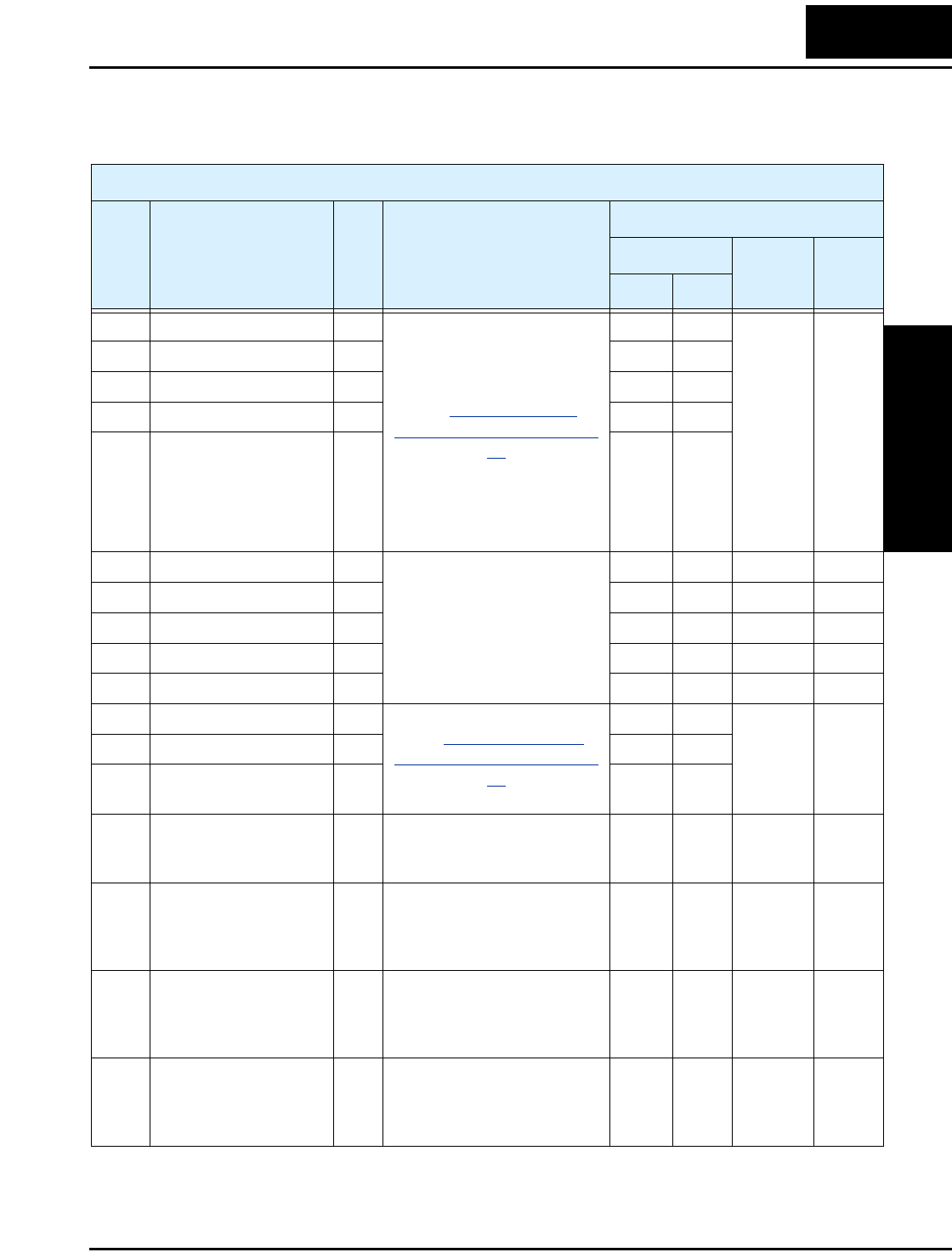
L2002 Inverter
Appendix B
B–39
The following table lists the holding registers for the “C” Group Intelligent Input
Functions.I
“C” Group Intelligent Terminal Functions
Func.
Code Name R/W Description
Network Data
Register
Range Res.
hex dec.
C001 Terminal [1] function R/W
See “Input Terminal
Configuration” on page 3–
47
1103h 04355 0, 1, 2, 3,
4, 5, 6, 7,
8, 9, 11,
12, 13,
15, 16,
18, 19,
20, 21,
22, 23,
24, 27,
28, 29,
31, 50,
51, 255
—
C002 Terminal [2] function R/W 1104h 04356
C003 Terminal [3] function R/W 1105h 04357
C004 Terminal [4] function R/W 1106h 04358
C005 Terminal [5] function R/W 1107h 04359
C011 Terminal [1] active state R/W Select logic convention, two
option codes:
00...normally open [NO]
01...normally closed [NC]
110Bh 04363 0, 1 —
C012 Terminal [2] active state R/W 110Ch 04364 0, 1 —
C013 Terminal [3] active state R/W 110Dh 04365 0, 1 —
C014 Terminal [4] active state R/W 110Eh 04366 0, 1 —
C015 Terminal [5] active state R/W 110Fh 04367 0, 1 —
C021 Terminal [11] function R/W
See “Output Terminal
Configuration” on page 3–
54
1114h 04372
0, 1, 2, 3,
4, 5, 6, 7,
8, 9
—
C022 Terminal [12] function R/W 1115h 04373
C026 Alarm relay terminal
function
R/W 1119h 04377
C028 [AM] signal selection R/W Two available functions:
00...Actual motor speed
01...Motor current
111Bh 04379 0, 1 —
C031 Terminal [11] active
state
R/W Select logic convention, two
option codes:
00...normally open (NO)
01...normally closed (NC)
111Dh 04381 0, 1 —
C032 Terminal [12] active
state
R/W Select logic convention, two
option codes:
00...normally open (NO)
01...normally closed (NC)
111Eh 04382 0, 1 —
C036 Alarm relay active state R/W Select logic convention, two
option codes:
00...normally open (NO)
01...normally closed (NC)
1122h 04370 0, 1 —

ModBus Data Listing
Appendix B
B–40
C041 Overload level setting R/W Sets the overload signal level
between 0% and 200% (from
0 to two times the rated
current of the inverter)
1124h 04388 0 to
20000
0.01 %
C042 Frequency arrival
setting for acceleration
R/W Sets the frequency arrival
setting threshold for the
output frequency during
acceleration, range is 0.0 to
400.0 Hz
1126h 04390 0 to 4000
*1
0.1 Hz
C043 Arrival frequency
setting for deceleration
R/W Sets the frequency arrival
setting threshold for the
output frequency during
deceleration, range is 0.0 to
400.0 Hz
1128h 04392 0 to 4000 0.1 Hz
C044 PID deviation level
setting
R/W Sets the allowable PID loop
error magnitude (absolute
value), SP - PV, range is 0.0 to
100%, resolution is 0.1%
1129h 04393 0 to 1000 0.1 %
C052 PID FBV function high
limit
R/W When the PV exceeds this
value, the PID loop turns OFF
the PID Second Stage Output,
range is 0.0 to 100.0%
112Eh 04398 0 to 1000 0.1 %
C053 PID FBV function low
limit
R/W When the PV goes below this
value, the PID loop turns ON
the PID Second Stage Output,
range is 0.0 to 100.0%
112Fh 04399 0 to 1000 0.1 %
C071 Communication speed
selection
—
NOTE: These network
settings are not accessible to
ModBus. Use the inverter
keypad or digital operator to
edit. Refer to “Network
Communication Settings”
on page 3–58.
1138h 04408 — —
C072 Node allocation — 1139h 04409 — —
C074 Communication parity
selection
— 113Bh 04411 — —
C075 Communication stop bit
selection
— 113Ch 04412 — —
C076 Communication error
select
— 113Dh 04413 — —
C077 Communication error
time-out
— 113Eh 04414 — —
C078 Communication wait
time
— 113Fh 04415 — —
“C” Group Intelligent Terminal Functions
Func.
Code Name R/W Description
Network Data
Register
Range Res.
hex dec.

L2002 Inverter
Appendix B
B–41
C081 O input span calibration R/W Scale factor between the
external frequency command
on terminals L – O (voltage
input) and the frequency
output, range is 0.0 to 200.0%
1141h 04417 0 to 2000 0.1 %
C082 OI input span calibra-
tion
R/W Scale factor between the
external frequency command
on terminals L – OI (current
input) and the frequency
output, range is 0.0 to 200.0%
1142h 04418 0 to 2000 0.1 %
C085 Thermistor input tuning R/W Range is 0.0 to 200.0% 1144h 04420 0 to 2000 0.1 %
C086 [AM] terminal offset
tuning
R/W Range is 0.0 to 10.0V 1145h 04421 0 to 100 0.1 V
C091 Debug mode enable R Displays debug parameters.
Two option codes:
00...Disable
01...Enable
1148h 04424 0, 1 —
C101 Up/Down memory
mode
selection
R/W Controls speed setpoint for
the inverter after power cycle.
Two option codes:
00...Clear last frequency
(return to default frequency
F001)
01...Keep last frequency
adjusted by UP/DWN
1149h 04425 0, 1 —
C102 Reset selection R/W Determines response to Reset
input [RST].
Three option codes:
00...Cancel trip state at input
signal ON transition, stops
inverter if in Run Mode
01...Cancel trip state at signal
OFF transition, stops inverter
if in Run Mode
02...Cancel trip state at input
signal ON transition, no effect
if in Run Mode
114Ah 04426 0, 1, 2 —
C141 Input A select for logic
output
R/W
See “Output Logic and
Timing” on page 3–61
1150h 04432 0, 1, 2, 3,
4, 5, 6, 7,
8, 9
—
C142 Input B select for logic
output
R/W 1151h 04433
“C” Group Intelligent Terminal Functions
Func.
Code Name R/W Description
Network Data
Register
Range Res.
hex dec.

ModBus Data Listing
Appendix B
B–42
Note 1: Assume that the inverter current rating is 10000 (for C041).
C143 Logic function select R/W Applies a logic function to
calculate [LOG] output state,
three options:
00 ... [LOG] = A AND B
01 ...[LOG] = A OR B
02 ...[LOG] = A XOR B
1152h 04434 0, 1, 2 —
C144 Terminal [11] ON delay R/W Range is 0.0 to 100.0 sec. 1153h 04435 0 to 1000 0.1 sec
C145 Terminal [11] OFF
delay
R/W Range is 0.0 to 100.0 sec. 1154h 04436 0 to 1000 0.1 sec
C146 Terminal [12] ON delay R/W Range is 0.0 to 100.0 sec. 1155h 04437 0 to 1000 0.1 sec
C147 Terminal [12] OFF
delay
R/W Range is 0.0 to 100.0 sec. 1156h 04438 0 to 1000 0.1 sec
C148 Output relay ON delay R/W Range is 0.0 to 100.0 sec. 1157h 04439 0 to 1000 0.1 sec
C149 Output relay OFF delay R/W Range is 0.0 to 100.0 sec. 1158h 04340 0 to 1000 0.1 sec
“C” Group Intelligent Terminal Functions
Func.
Code Name R/W Description
Network Data
Register
Range Res.
hex dec.

L2002 Inverter
Appendix B
B–43
The following table lists the holding registers for the “H” Group Motor Constants.
“H” Group Motor Constants
Func.
Code Name R/W Description
Network Data
Register
Range Res.
hex dec.
H003 Motor capacity R/W Thirteen selections:
0 .....0.20 kW
1 .....0.37 kW
2 .....0.40 kW
3 .....0.55 kW
4 .....0.75 kW
5 .....1.10 kW
6 .....1.50 kW
7 .....2.2 kW
8 .....3.0 kW
9 .....3.7 kW
10 ...4.0 kW
11 ...5.5 kW
12 ...7.5 kW
1165h 04453 0 to 12 —
H203 Motor capacity, 2nd
setting
R/W 1540h 05440 0 to 12 —
H004 Motor poles setting R/W Four selections:
2 / 4 / 6 / 8
1166h 04454 2, 4, 6,
8
1 pole
H204 Motor poles setting, 2nd
motor
R/W 1541h 05441 2, 4, 6,
8
1 pole
H006 Motor stabilization
constant
R/W Motor constant (factory set),
range is 0 to 255
1168h 04456 0 to 255 1
H206 Motor stabilization
constant, 2nd motor
R/W 1543h 05443 0 to 255 1


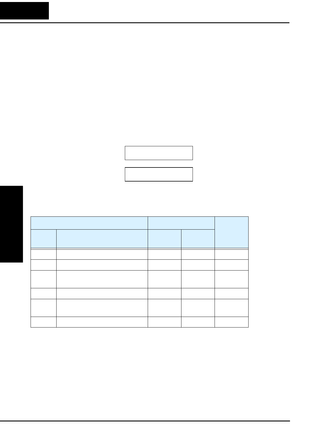
Introduction
Appendix C
C–2
Introduction
This appendix lists the user-programmable parameters for the L2002 series inverters and
the default values for European and U.S. product types. The right-most column of the
tables is blank, so you can record values you have changed from the default. This
involves just a few parameters for most applications. This appendix presents the parame-
ters in a format oriented toward the keypad on the inverter.
Parameter Settings for Keypad Entry
L2002 series inverters provide many functions and parameters that can be configured by
the user. We recommend that you record all parameters that have been edited, in order to
help in troubleshooting or recovery from a loss of parameter data.
Main Profile Parameters
}This information is printed
on the specification label
located on the right side of
the inverter.
L2002Inverter model
MFG. No.
“F” Group Parameters Default Setting
User
Setting
Func.
Code Name –FE(F)
(Europe)
–FU
(USA)
F001 Output frequency setting 0.0 0.0
F002 Acceleration (1) time setting 10.0 10.0
F202 Acceleration (1) time setting, 2nd
motor
10.0 10.0
F003 Deceleration (1) time setting 10.0 10.0
F203 Deceleration (1) time setting, 2nd
motor
10.0 10.0
F004 Keypad Run key routing 00 00
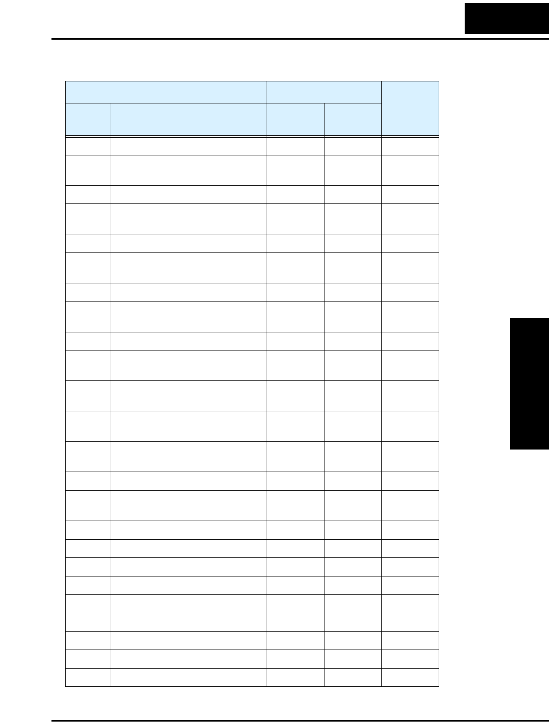
L2002 Inverter
Appendix C
C–3
Standard Functions
“A” Group Parameters Default Setting
User
Setting
Func.
Code Name -FE(F)
(EU)
-FU
(USA)
A001 Frequency source setting 01 00
A201 Frequency source setting, 2nd
motor
01 00
A002 Run command source setting 01 02
A202 Run command source setting,
2nd motor
01 02
A003 Base frequency setting 50.0 60.0
A203 Base frequency setting, 2nd
motor
50.0 60.0
A004 Maximum frequency setting 50.0 60.0
A204 Maximum frequency setting, 2nd
motor
50.0 60.0
A005 [AT] selection 00 00
A011 O–L input active range start
frequency
0.0 0.0
A012 O–L input active range end
frequency
0.0 0.0
A013 O–L input active range start
voltage
0.0 0.0
A014 O–L input active range end
voltage
100. 100.
A015 O–L input start frequency enable 01 01
A016 External frequency filter time
constant
2. 8.
A020 Multi-speed 0 setting 0.0 0.0
A220 Multi-speed 0 setting, 2nd motor 0.0 0.0
A021 Multi-speed 1 setting 0.0 0.0
A022 Multi-speed 2 setting 0.0 0.0
A023 Multi-speed 3 setting 0.0 0.0
A024 Multi-speed 4 setting 0.0 0.0
A025 Multi-speed 5 setting 0.0 0.0
A026 Multi-speed 6 setting 0.0 0.0
A027 Multi-speed 7 setting 0.0 0.0
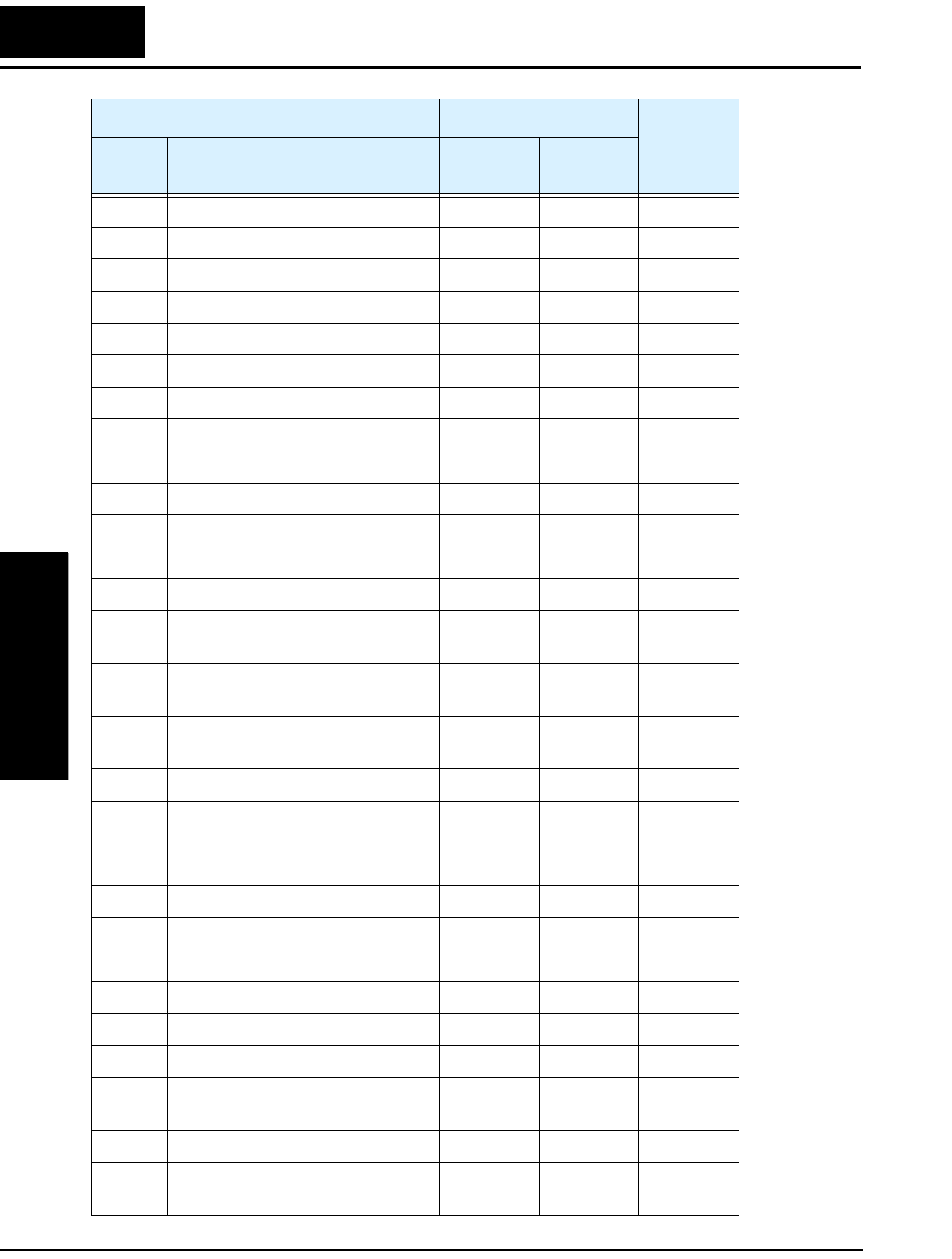
Parameter Settings for Keypad Entry
Appendix C
C–4
A028 Multi-speed 8 setting 0.0 0.0
A029 Multi-speed 9 setting 0.0 0.0
A030 Multi-speed 10 setting 0.0 0.0
A031 Multi-speed 11 setting 0.0 0.0
A032 Multi-speed 12 setting 0.0 0.0
A033 Multi-speed 13 setting 0.0 0.0
A034 Multi-speed 14 setting 0.0 0.0
A035 Multi-speed 15 setting 0.0 0.0
A038 Jog frequency setting 1.00 1.00
A039 Jog stop mode 00 00
A041 Torque boost select 00 00
A241 Torque boost select, 2nd motor 00 00
A042 Manual torque boost value 1.8 1.8
A242 Manual torque boost value, 2nd
motor
0.0 0.0
A043 Manual torque boost frequency
adjustment
10.0 10.0
A243 Manual torque boost frequency
adjustment, 2nd motor
0.0 0.0
A044 V/f characteristic curve selection 00 00
A244 V/f characteristic curve selec-
tion, 2nd motor
00 00
A045 V/f gain setting 100. 100.
A245 V/f gain setting, 2nd motor 100. 100.
A051 DC braking enable 00 00
A052 DC braking frequency setting 0.5 0.5
A053 DC braking wait time 0.0 0.0
A054 DC braking force for deceleration 0 0
A055 DC braking time for deceleration 0.0 0.0
A056 DC braking / edge or level detec-
tion for [DB] input
01 01
A061 Frequency upper limit setting 0.0 0.0
A261 Frequency upper limit setting,
2nd motor
0.0 0.0
“A” Group Parameters Default Setting
User
Setting
Func.
Code Name -FE(F)
(EU)
-FU
(USA)

L2002 Inverter
Appendix C
C–5
A062 Frequency lower limit setting 0.0 0.0
A262 Frequency lower limit setting,
2nd motor
0.0 0.0
A063,
A065,
A067
Jump (center) frequency setting 0.0 0.0
A064,
A066,
A068
Jump (hysteresis) frequency
width setting
0.5 0.5
A071 PID Enable 00 00
A072 PID proportional gain 1.0 1.0
A073 PID integral time constant 1.0 1.0
A074 PID derivative time constant 0.0 0.0
A075 PV scale conversion 1.00 1.00
A076 PV source setting 00 00
A077 Reverse PID action 00 00
A078 PID output limit 0.0 0.0
A081 AVR function select 00 00
A082 AVR voltage select 230/400 230/460
A092 Acceleration (2) time setting 15.00 15.00
A292 Acceleration (2) time setting,
(2nd motor)
15.00 15.00
A093 Deceleration (2) time setting 15.00 15.00
A293 Deceleration (2) time setting,
(2nd motor)
15.00 15.00
A094 Select method to switch to Acc2/
Dec2 profile
00 00
A294 Select method to switch to Acc2/
Dec2 profile, 2nd motor
00 00
A095 Acc1 to Acc2 frequency transi-
tion point
0.0 0.0
A295 Acc1 to Acc2 frequency transi-
tion point, 2nd motor
0.0 0.0
A096 Dec1 to Dec2 frequency transi-
tion point
0.0 0.0
“A” Group Parameters Default Setting
User
Setting
Func.
Code Name -FE(F)
(EU)
-FU
(USA)

Parameter Settings for Keypad Entry
Appendix C
C–6
A296 Dec1 to Dec2 frequency transi-
tion point, 2nd motor
0.0 0.0
A097 Acceleration curve selection 00 00
A098 Deceleration curve selection 00 00
A101 [OI]–[L] input active range start
frequency
0.0 0.0
A102 [OI]–[L] input active range end
frequency
0.0 0.0
A103 [OI]–[L] input active range start
current
0.0 0.0
A104 [OI]–[L] input active range end
current
100. 100.
A105 [OI]–[L] input start frequency
enable
01 01
A141 A input select for calculate
function
02 02
A142 B input select for calculate
function
03 03
A143 Calculation symbol 00 00
A145 ADD frequency 0.0 0.0
A146 ADD direction select 00 00
A151 Pot. input active range start
frequency
0.0 0.0
A152 Pot. input active range end
frequency
0.0 0.0
A153 Pot. input active range start
current
0.0 0.0
A154 Pot. input active range end
current
0.0 0.0
A155 Pot. input start frequency enable 01 01
“A” Group Parameters Default Setting
User
Setting
Func.
Code Name -FE(F)
(EU)
-FU
(USA)

L2002 Inverter
Appendix C
C–7
Fine Tuning Functions
“B” Group Parameters Default Setting
User
Setting
Func.
Code Name -FE(F)
(EU)
-FU
(USA)
B001 Selection of automatic restart
mode
00 00
B002 Allowable under-voltage power
failure time
1.0 1.0
B003 Retry wait time before motor
restart
1.0 1.0
B004 Instantaneous power failure /
under-voltage trip alarm enable
00 00
B005 Number of restarts on power
failure / under-voltage trip events
00 00
B012 Level of electronic thermal
setting
Rated
current for
each
inverter
Rated
current for
each
inverter
B212 Level of electronic thermal
setting, 2nd motor
Rated
current for
each
inverter
Rated
current for
each
inverter
B013 Electronic thermal characteristic 01 01
B213 Electronic thermal characteristic,
2nd motor
01 01
B021 Overload restriction operation
mode
01 01
B221 Overload restriction operation
mode, 2nd motor
01 01
B022 Overload restriction setting Rated
current x
1.5
Rated
current x
1.5
B222 Overload restriction setting, 2nd
motor
Rated
current x
1.5
Rated
current x
1.5
B023 Deceleration rate at overload
restriction
1.0 30.0
B223 Deceleration rate at overload
restriction, 2nd motor
1.0 30.0
B028 Overload restriction source
selection
00 00
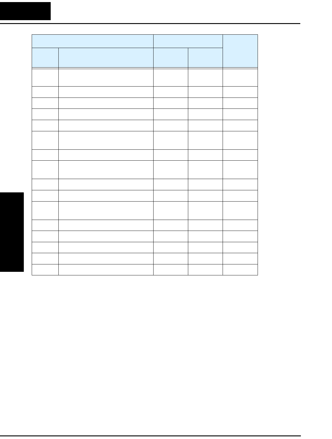
Parameter Settings for Keypad Entry
Appendix C
C–8
B228 Overload restriction source
selection, 2nd motor
00 00
B031 Software lock mode selection 01 01
B080 [AM] analog signal gain 100. 100.
B082 Start frequency adjustment 0.5 0.5
B083 Carrier frequency setting 5.0 5.0
B084 Initialization mode (parameters
or trip history)
00 00
B085 Country code for initialization 01 02
B086 Frequency scaling conversion
factor
1.0 1.0
B087 STOP key enable 00 00
B088 Restart mode after FRS 00 00
B089 Monitor display select for
networked inverter
01 01
B091 Stop mode selection 00 00
B130 Over-voltage LADSTOP enable 00 00
B131 Over-voltage LADSTOP level 380 / 760 380 / 760
B150 Carrier mode 00 00
B151 Quick start enable 00 00
“B” Group Parameters Default Setting
User
Setting
Func.
Code Name -FE(F)
(EU)
-FU
(USA)

L2002 Inverter
Appendix C
C–9
Intelligent Terminal Functions
“C” Group Parameters Default Setting
User
Setting
Func.
Code Name -FE(F)
(EU)
-FU
(USA)
C001 Terminal [1] function 00 00
C201 Terminal [1] function, 2nd motor 00 00
C002 Terminal [2] function 01 01
C202 Terminal [2] function, 2nd motor 01 01
C003 Terminal [3] function 02 16
C203 Terminal [3] function, 2nd motor 02 16
C004 Terminal [4] function 03 13
C204 Terminal [4] function, 2nd motor 03 13
C005 Terminal [5] function 18 09
C205 Terminal [5] function, 2nd motor 18 09
C011 Terminal [1] active state 00 00
C012 Terminal [2] active state 00 00
C013 Terminal [3] active state 00 00
C014 Terminal [4] active state 00 01
C015 Terminal [5] active state 00 00
C021 Terminal [11] function 01 01
C022 Terminal [12] function 00 00
C026 Alarm relay terminal function 05 05
C028 [AM] signal selection 00 00
C031 Terminal [11] active state 00 00
C032 Terminal [12] active state 00 00
C036 Alarm relay active state 01 01
C041 Overload level setting Inverter
rated
current
Inverter
rated
current
C241 Overload level setting, 2nd motor Inverter
rated
current
Inverter
rated
current
C042 Frequency arrival setting for
acceleration
0.0 0.0
C043 Arrival frequency setting for
deceleration
0.0 0.0

Parameter Settings for Keypad Entry
Appendix C
C–10
C044 PID deviation level setting 3.0 3.0
C052 PID FBV function high limit 100.0 100.0
C053 PID FBV function low limit 0.0 0.0
C071 Communication speed selection 06 04
C072 Node allocation 1. 1.
C074 Communication parity selection 00 00
C075 Communication stop bit selection 1 1
C076 Communication error select 02 02
C077 Communication erorr time-out 0.00 0.00
C078 Communication wait time 0. 0.
C081 O input span calibration 100.0 100.0
C082 OI input span calibration 100.0 100.0
C085 Thermistor input tuning 100.0 100.0
C086 [AM] terminal offset tuning 0.0 0.0
C091 Debug mode enable 00 00
C101 Up/Down memory mode
selection
00 00
C102 Reset selection 00 00
C141 Input A select for logic output 00 00
C142 Input B select for logic output 01 01
C143 Logic function select 00 00
C144 Terminal [11] ON delay 0.0 0.0
C145 Terminal [11] OFF delay 0.0 0.0
C146 Terminal [12] ON delay 0.0 0.0
C147 Terminal [12] OFF delay 0.0 0.0
C148 Output relay ON delay 0.0 0.0
C149 Output relay OFF delay 0.0 0.0
“C” Group Parameters Default Setting
User
Setting
Func.
Code Name -FE(F)
(EU)
-FU
(USA)

L2002 Inverter
Appendix C
C–11
Motor Constants Functions
“H” Group Parameters Default Setting
User
Setting
Func.
Code Name -FE(F)
(EU)
-FU
(USA)
H003 Motor capacity Specified
by the
inverter
capacity
Specified
by the
inverter
capacity
H203 Motor capacity, 2nd setting Specified
by the
inverter
capacity
Specified
by the
inverter
capacity
H004 Motor poles setting 4 4
H204 Motor poles setting, 2nd motor 4 4
H006 Motor stabilization constant 100 100
H206 Motor stabilization constant, 2nd
motor
100 100

Parameter Settings for Keypad Entry
Appendix C
C–12
Expansion Card Functions
“P” Group Parameters Default Setting
User
Setting
Func.
Code Name -FE(F)
(EU)
-FU
(USA)
P044 Network comm watchdog timer 1.00 1.00
P045 Inverter action on network comm
error
01 01
P046 Polled I/O output instance
number
21 21
P047 Polled I/O input instance number 71 71
P048 Inverter action on network idle
mode
01 01
P049 Network motor poles setting for
RPM
00


CE–EMC Installation Guidelines
Appendix D
D–2
CE–EMC Installation Guidelines
You are required to satisfy the EMC directive (89/336/EEC) when using an L2002
inverter in an EU country. To satisfy the EMC directive and to comply with standard,
follow the guidelines in this section.
1. As user you must ensure that the HF (high frequency) impedance between adjustable
frequency inverter, filter, and ground is as small as possible.
• Ensure that the connections are metallic and have the largest possible contact
areas (zinc-plated mounting plates).
2. Avoid conductor loops that act like antennas, especially loops that encompass large
areas.
• Avoid unnecessary conductor loops.
• Avoid parallel arrangement of low-level signal wiring and power-carrying or
noise-prone conductors.
3. Use shielded wiring for the motor cable and all analog and digital control lines.
• Allow the effective shield area of these lines to remain as large as possible; i.e., do
not strip away the shield (screen) further away from the cable end than absolutely
necessary.
• With integrated systems (for example, when the adjustable frequency inverter is
communicating with some type of supervisory controller or host computer in the
same control cabinet and they are connected at the same ground + PE-potential),
connect the shields of the control lines to ground + PE (protective earth) at both
ends. With distributed systems (for example the communicating supervisory
controller or host computer is not in the same control cabinet and there is a
distance between the systems), we recommend connecting the shield of the
control lines only at the end connecting to the adjustable frequency inverter. If
possible, route the other end of the control lines directly to the cable entry section
of the supervisory controller or host computer. The shield conductor of the motor
cables always must connected to ground + PE at both ends.
• To achieve a large area contact between shield and ground + PE-potential, use a
PG screw with a metallic shell, or use a metallic mounting clip.
• Use only cable with braided, tinned copper mesh shield (type “CY”) with 85%
coverage.
• The shielding continuity should not be broken at any point in the cable. If the use
of reactors, contactors, terminals, or safety switches in the motor output is neces-
sary, the unshielded section should be kept as short as possible.
• Some motors have a rubber gasket between terminal box and motor housing. Very
often, the terminal boxes, and particularly the threads for the metal PG screw
connections, are painted. Make sure there is always a good metallic connection
between the shielding of the motor cable, the metal PG screw connection, the
terminal box, and the motor housing. If necessary, carefully remove paint between
conducting surfaces.

L2002 Inverter
Appendix D
D–3
4. Take measures to minimize interference that is frequently coupled in through installa-
tion cables.
• Separate interfering cables with 0.25m minimum from cables susceptible to inter-
ference. A particularly critical point is laying parallel cables over longer distances.
If two cables intersect (one crosses over the other), the interference is smallest if
they intersect at an angle of 90°. Cables susceptible to interference should there-
fore only intersect motor cables, intermediate circuit cables, or the wiring of a
rheostat at right angles and never be laid parallel to them over longer distances.
5. Minimize the distance between an interference source and an interference sink (inter-
ference-threatened device), thereby decreasing the effect of the emitted interference
on the interference sink.
• You should use only interference-free devices and maintain a minimum distance
of 0.25 m from the adjustable frequency inverter.
6. Follow safety measures in the filter installation.
• Ensure that the ground terminal (PE) of the filter is properly connected to the
ground terminal of the adjustable frequency inverter. An HF ground connection
via metal contact between the housings of the filter and the adjustable frequency
inverter, or solely via cable shield, is not permitted as a protective conductor
connection. The filter must be solidly and permanently connected with the ground
potential so as to preclude the danger of electric shock upon touching the filter if a
fault occurs.
To achieve a protective ground connection for the filter:
• Ground the filter with a conductor of at least 10 mm2 cross-sectional area.
• Connect a second grounding conductor, using a separate grounding terminal
parallel to the protective conductor. (The cross section of each single protective
conductor terminal must be sized for the required nominal load.)
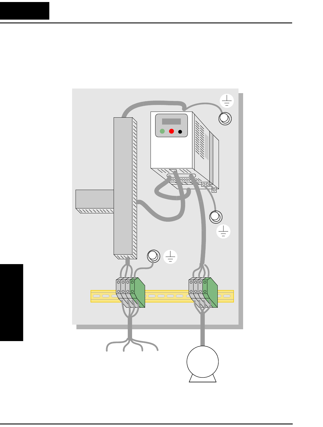
CE–EMC Installation Guidelines
Appendix D
D–4
Some L2002 inverters designed for use in Europe (–xxxLFEF/xxxHFEF models) have
built-in line filters. Inverter models –xxxLFE/xxxHFE do not have built-in line filters. In
the event your application needs additional filtering, the following diagrams show
control panel mounting and wiring examples for different filter types.
L1 L2L3 PE M
3~
L2002 inverter with footprint-type filter
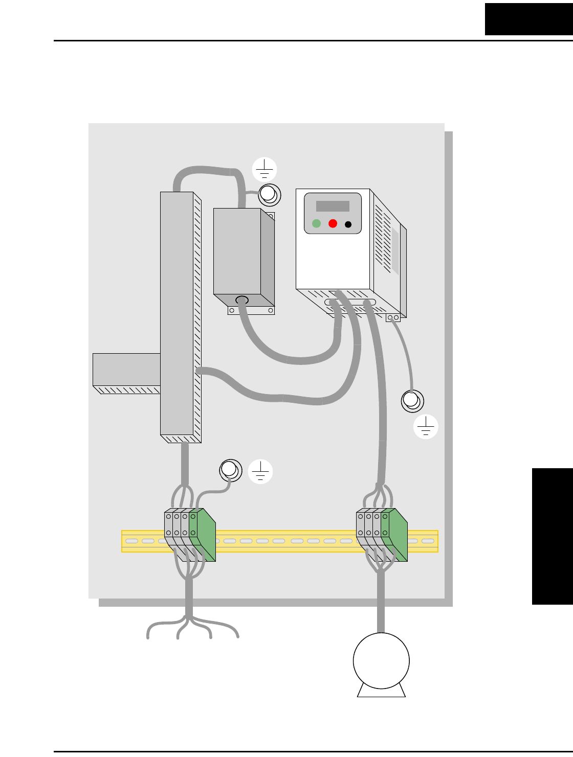
L2002 Inverter
Appendix D
D–5
L1 L2L3 PE
L2002 inverter with book-type filter
M
3~

Hitachi EMC Recommendations
Appendix D
D–6
Hitachi EMC Recommendations
WARNING: This equipment should be installed, adjusted, and serviced by qualified
personal familiar with construction and operation of the equipment and the hazards
involved. Failure to observe this precaution could result in bodily injury.
Use the following checklist to ensure the inverter is within proper operating ranges and
conditions.
1. The power supply to L2002 inverters must meet these specifications:
• Voltage fluctuation ±10% or less
• Voltage imbalance ±3% or less
• Frequency variation ±4% or less
• Voltage distortion THD = 10% or less
2. Installation measure:
• Use a filter designed for L2002 inverter.
3. Wiring:
• Shielded wire (screened cable) is required for motor wiring, and the length must
be less than 5 meters.
• The carrier frequency setting must be less than 5 kHz to satisfy EMC require-
ments.
• Separate the power input and motor wiring from the signal/process circuit wiring.
4. Environmental conditions—when using a filter, follow these guidelines:
• Ambient temperature: –10 to 40 °C
• Humidity: 20 to 90% RH (non-condensing)
• Vibration: 5.9 m/sec2 (0.6 G) 10 ~ 55Hz
• Location: 1000 meters or less altitude, indoors (no corrosive gas or dust)

Index
A
A Group functions 3–10
AC reactors 5–3
Acceleration 1–22, 3–9
characteristic curves 3–28
second function 3–26
two-stage 4–18
Access levels 3–5, 3–39, 4–22
Accessories 5–2
ADD frequency 3–31
enable input 4–32
Alarm signal 4–36, 4–43
Algorithms, torque control 3–5, 3–63
Ambient temperature 2–10, A–2
Analog inputs
calibration settings 3–59
current/voltage select 4–23
disconnect detect 4–45
operation 4–53
settings 3–14, 3–29
wiring examples 4–53
Analog outputs
configuration 3–56
operation 4–55
Arrival frequency A–2
Automatic restart 3–33
Automatic voltage regulation 2–29, 3–25
Auto-tuning A–2
AVR 2–29, 3–25
B
B Group functions 3–33
Base frequency 2–29, A–2
setting 3–13
Bibliography A–8
Braking 1–21
dynamic 5–5
resistive 1–24
settings 3–21
Braking resistor 2–7, A–2
Braking resistor selection
external braking units 5–5
Braking unit 2–7
Break-away torque A–2
C
C Group functions 3–47
Calculate function 3–30
Capacitor life curve 6–11
Carrier frequency 3–41, A–2
Catching a spinning motor 3–42
Cautions
general ix
index to... iv
inverter mounting 2–9
operating procedures 4–2
CE approval A–2
CE-EMC guidelines D–2
Chassis ground connection 1–24, 2–21
error code 6–6

Index–2
Choke 2–7, 5–4, A–2
Chopper frequency 3–41
Circuit breaker sizes xiv, 2–17
Clearance for ventilation 2–10
Coasting 3–42
Connectors
logic terminals 2–4
removal 2–4
serial port B–3
Constant torque 3–18
Constant volts/hertz operation 1–19
Contact information xviii
Control algorithms 3–18
Copy unit 1–3, 3–2
Cover removal 2–3
Current input 3–14
Current overload 2–30, 3–37
Current/voltage analog input select 4–23
D
D Group parameters 3–6
DC braking 3–21, 4–15, 4–16, A–3
Deadband A–3
Deceleration 1–22, 3–9, 4–15
characteristic curves 3–28
second function 3–26
two-stage 4–18
Default settings
listing C–2
restoring 6–8
Delay function, output circuits 3–62, 4–37
Derating curves 1–12
Derivative gain 3–24
Digital operator 1–3, 2–24, 3–3, A–3
Dimensions
inverter 2–11
terminals 2–18
Diode A–3
DIP switch configuration 2–5, 2–27, 3–11, 4–
9, B–4
Disconnect detect, analog input 4–45
Duty cycle A–3
Dynamic braking 1–21, 5–5, A–3
usage 5–5
E
Editing parameters 2–24, 2–27
in Run Mode 3–5, 3–39, 4–22
Electromagnetic compatibility D–2
Electronic thermal overload xiv
configuration 3–35
error code 6–5
EMC installation
guidelines D–2
recommendations D–6
EMI A–3
EMI filter xi, 5–4
Environmental specs 1–10
Error codes, trip events 6–5
Error, PID loop 4–42, A–3
Event clearing 4–24
Expansion card functions 3–64
External trip 4–20
error code 6–6
F
F Group functions 3–9
Factory default settings 3–41
restoring 6–8
Fan outlet 2–10, 2–22
FAQ 1–23
Features 1–2, 2–2
Filters, noise suppression 5–2
Fine-tuning functions 3–33
Force operation from digital operator 4–31
Force terminal mode 4–33
Forward run command 4–12
Four-quadrant operation A–3
Free-run stop 3–42, 4–15, 4–19, A–4
Frequency arrival signals 4–39
Frequency display scaling 3–41
Frequency limits 3–22
Frequency matching 3–42
Frequency setting A–4
Frequency source setting 3–10, 4–31, 4–33
Frequency-related functions 3–22
Frequently asked questions 1–23
Functions 1–21, 2–25
Fuse sizes xiv, 2–17

L2002 Inverter Index–3
G
Glossary of terms A–2
H
H Group parameters 3–63
Harmonics A–4
History of trip events 3–7
Horsepower A–4
I
IGBT 1–18, A–4
test method 6–15
Index of terminal functions 4–7
Inertia A–4
Initialization 6–8
codes 3–41
Input circuits 4–4, 4–9
Inspection
electrical measurements 6–12
IGBT test method 6–15
measurement techniques 6–14
procedures 6–9
unpacking 2–2
Installation instructions 2–8
Instantaneous power failure alarm 3–34
Insulation test 6–10
Integral gain 3–24
Intelligent input terminals 3–47, 4–9
Intelligent output terminals 3–54, 4–35
Intelligent terminals
definition A–4
functions 3–47
index 4–7
Inverter 1–23, A–4
dimensions 2–11
specifications 1–5
iSLV 3–18
Isolation transformer A–4
J
Jog command 4–15
Jog frequency settings 3–16
Jogging operation A–5
Jump frequencies 3–23, A–5
K
Keypad 1–3, 2–2, 3–2
features 2–24, 3–3
navigation 2–26, 3–4
navigation, trip events 6–7
L
LEDs 2–23, 2–24, 2–32, 3–3
Line reactor A–5
Linear accel/decel 3–28
Logic output function 3–61, 4–50
Logic terminals 2–4, 3–47, 3–54, 4–6
M
Main profile parameters 3–9
Maintenance procedures 6–9
Manual torque boost 3–18
Maximum frequency setting 3–13
Megger test 6–10
ModBus
data listing B–19
introduction to network B–2
Model number
convention 1–4
on nameplate 1–4
Momentum A–5
Monitor mode 2–26, 2–32, 2–33, 3–4, 3–5, 6–
5
Monitoring functions 3–6
Motor
constants 3–63
load A–5
poles 1–24, 2–31, 3–63
speed 2–33
voltage selection 3–63
wiring 2–21
Mounting
clearance for ventilation 2–10
dimensions 2–11
location 2–9
Multiple motors, configuration 4–58
Multi-speed
operation 4–13, A–5
profiles 1–22
settings 3–16

Index–4
N
Nameplate 1–4
Navigational map 2–26, 3–4
trip events 6–7
NEC A–5
NEMA
definition A–5
rated installation 1–3
Network communications 1–23, B–2
detection signal 4–49, 4–52
error code 6–6
local monitoring 3–8
ModBus data listing B–19
parameter settings B–5
protocol reference B–6
termination resistor B–4
Noise filters 5–2
AC reactor 2–7
O
OPE/485 serial port configuration 2–5, B–4
Open-collector outputs 4–35, A–5
Operational modes 3–5
Operator interfaces 1–3
Option card detection signal 4–52
Optional components 1–2, 2–7
Orientation 2–2
Output circuits 4–4, 4–35
delay function 3–62, 4–37
Output deviation for PID control 4–42
Output frequency 2–32
setting 3–9
Output function adjustment parameters 3–56
Output overload 3–37
Output terminals 2–21
Over-current trip 3–33
Overload advance notice signal 4–41
Overload protection xiv
configuration 3–35
error code 6–5
Overload restriction 3–37
Override, source settings 3–12
Over-voltage LADSTOP functions 3–44
Over-voltage trip 3–33
error code 6–5, 6–6
P
P Group functions 3–64
Parameter editing 2–24, 2–27
Parameter settings 1–21, 2–25
listings C–2
PID loop 1–25
clear input 4–28
configuration 4–57
definition A–5
error 4–42, A–3
error inversion 4–57
ON/OFF input 4–28
operation 4–56
output limit 4–57
process variable, definition A–6
second stage output 4–46
settings 3–24
PLC, connecting to 4–4
Poles of motor 1–24, 2–31, 3–63
Potentiometer 2–27, 3–10, 4–53
Power factor A–5
Power fail 3–33
Powerup Test 2–22
observations 2–33
Powerup, unattended start 4–21
error code 6–6
Preventative maintenance 6–9
Process variable A–6
Program mode 2–26, 2–33, 3–4, 3–5
Programming device 3–2
Proportional gain 3–24
PV source setting 3–24
PWM A–6
Q
Quick start enable 4–34

L2002 Inverter Index–5
R
Ratings label 1–4
Reactance A–6
Read/write copy unit 1–3
Ready input 4–34
Rectifier A–6
Reduced torque 3–18
Regenerative braking A–6
Regulation A–6
Regulatory agency approvals 1–4
Relay
alarm signal contacts 4–43
as intelligent output 4–36
Remote control 4–29
Reset function 3–60, 4–24
Restart Mode configuration 3–42
Reverse run command 4–12
Reverse torque A–6
Revision history xvii
RF noise filter 5–4
RJ-45 modular connector B–3
Rotor A–6
RPM 2–33
Run command 4–12
Run command source setting 2–28, 3–10, 4–
31, 4–33
Run mode 2–33, 3–5
Run signal 4–38
Running the motor 2–32
Run-time edits 3–5, 3–39, 4–22
S
Safety messages i
Saturation voltage A–6
Scaling 3–41
S-curve accel/decel 3–28
Second accel and decel 3–26
Second motor 4–17
Second stage output 4–46
Sensorless vector control A–6
Sepcial-Set 2nd motor 4–17
Serial port B–3
Service, warranty 6–16
Set 2nd motor 4–17, 4–58
Setpoint A–7
Single-phase power A–7
Sink/source input configuration 4–9
Slip
definition A–7
Software lock 3–5, 3–39, 4–22
Source/sink input configuration 2–5
Spare parts 6–11
Specifications
control logic signals 1–11, 4–6
derating curves 1–12
general 1–10
inverter 1–5
inverter label 1–4
Speed control 1–18, 1–22, 4–13
Speed pot 2–27
Squirrel cage A–7
Standard functions 3–10
Start frequency 3–41
Stator A–7
Stop command 4–12
Stop Mode configuration 3–42
Supply wiring 2–18
Switches, configuration 2–5
Switching frequency 3–41
Symbol definitions i
System description 2–7

Index–6
T
Tachometer A–7
Technical support xviii
Term definitions A–2
Terminal/program source configuration 2–5,
2–27, 3–11
Terminals
arrangement 2–19
listing 4–7
torque specs xiii, 2–18
Termination resistor, network B–4
Thermal protection
inverter, error code 6–6
motor 4–25
Thermal switch A–7
Thermistor
definition A–7
error code 6–6
input terminal 4–25
input tuning 3–59
Three-phase power
definition A–7
motor phase connections 1–19
wiring precautions 2–20
Three-wire interface operation 4–26
Torque 1–19, A–8
Torque boost 3–18
Torque control algorithms 3–5, 3–18, 3–63
Torque specs, terminals xiii, 2–18
Transistor A–8
Trip events 3–7, 4–24
clearing 6–5
definition A–8
error codes 6–5
external input 4–20
history of 6–7
monitoring 6–5
Troubleshooting tips 6–3
Two-stage accel/decel 4–18
U
UL instructions xii
Unattended start protection 4–21
error code 6–6
Under-voltage alarm 3–34
Under-voltage trip 3–33
error code 6–5, 6–6
Unpacking 2–2
Up/Down functions 4–29
V
V/f control 3–18
Variable torque 3–18
Variable-frequency drives
introduction 1–18
Velocity profile 1–22
Ventilation 2–10, 2–22
Voltage gain 3–19
Voltage input 3–14
W
Warnings
general ix
index to... iv
operating procedures 4–3
troubleshooting 6–2
Warranty 6–16
Watt loss A–8
Wiring
access 2–6
analog inputs 4–53
gauge xiii, 2–17
inverter output 2–21
logic connectors 2–21, 4–6
power input 2–18
preparation 2–16
relay contacts 4–6
system diagram 4–5
Z
Zero-phase reactor 5–4
