Hitec RCD ECL7PRO24G 2.4GHz RADIO CONTROL SYSTEM User Manual
Hitec RCD Inc. 2.4GHz RADIO CONTROL SYSTEM Users Manual
Users Manual
ECLIPSE 7 PRO 2.4G
2.4GHz Radio Control System
USER MANUAL
Hitec RCD KOREA INC.
Introducing the ECLIPSE 7 PRO 2.4G
Congratulations and welcome to the R/C world! You now own a basic, but unusually versatile and
powerful, 5-Channel beginner’s RC transmitter.
The ECLIPSE 7 PRO 2.4G is all the radio you need to fly the most of 5-Channel fixed-wings aircraft
models. Standard features include servo-reversing for all channels, trim adjustments on all control
channels, ATV (Adjustable Travel Volume) on Aileron (CH.1) and Elevator (CH.2).
The ECLIPSE 7 PRO 2.4G features:
Pre-mixed Flight Control Functions:
The ECLIPSE 7 PRO 2.4G computer automatically mixes rudder and elevator outputs to control a V-
tail or mixes aileron and elevator outputs to create elevons for tail-less flying wings, eliminating the
need for on-board mixing systems.
Trim Adjustment Function:
This computerized radio allows you to easily tune and coordinate the control surfaces (such as
keeping a rudder centered or two ailerons-each on their own servo-moving the same amount) without
having to physically re-adjust linkages.
Buddy-Box Function:
For those learning to fly, the transmitter has a "buddy-box" capability so that you can use the optional
trainer cord to connect your ECLIPSE 7 PRO 2.4G to another Hitec transmitter (Master)*. This
function allows one transmitter to be used by an instructor as the primary flight control while the other
is controlled by the student pilot.
*Note: ECLIPSE 7 PRO 2.4G only can be used as a Pupil (Slave) transmitter.
If you are new to Computerized RC Transmitters
If ECLIPSE 7 PRO 2.4G is your first radio control transmitter, you're probably feeling a bit overwhelmd.
However, if you take little time to read this manual and follow the programming steps as you watch
your model's control surfaces respond, handling the ECLIPSE 7 PRO 2.4G will soon become quite
comfortable. So stick with it. Learning the programming basics won't take any longer or require any
more brain power than it takes to do the average crossword or Sudoku puzzle.
You'll discover that the rewards for mastering this simple radio are well worth the effort.
TIP:
Throughout the manual you will see our "Tip Sheet" notes.
These highlight specific function details we didn't want you to miss within the body of the manual.
Check these out; they can make programming the Optic Sport easier.
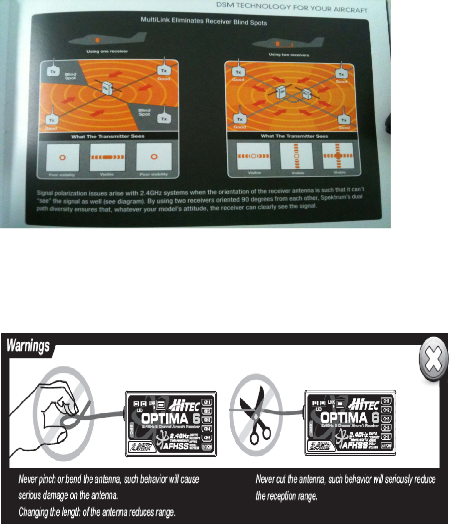
Hitec AFHSS 2.4GHz Technology
Most of Hitec’s 2.4GHz product uses AFHSS (Advanced Frequency Hopping Spread Spectrum)
technology which gives you highly stable one-way and telemetric signals for ensure safe flight of your
model aircrafts.
Equipment Mounting
When you mount each servo, use the supplied rubber grommets and insert an eyelet up through the
bottom. Be sure not to over tighten the screws.
If any portion of the servo case directly contacts the fuselage or the servo rails, the rubber grommets
will not be able to attenuate vibration, which can lead to mechanical wear and possible servo failure.
Servo Throw
Once you have installed the servos, operate each one over its full travel and check that the pushrod
and output arms do not bind or collide with each other, even at extreme trim settings.
Check to see that each control linkage does not require undue force to move (if you hear a servo
buzzing when there is no transmitter control motion, most likely there is too much friction in the control
or pushrod).
Even though the servo will tolerate loads like this, they will drain the battery pack much more rapidly
Receiver Installation and Setup Note:
Vibration and Water
The receiver contains precision electronic parts. Be sure to avoid vibration, shock, and temperature
extremes.
For protection, wrap the receiver in the provided "Flight Preserver" foam rubber, or use some other
vibration-absorbing materials.
If you are flying near bodies of water, it's also a good idea to protect the receiver by placing it in a
plastic bag and securing the open end of the bag with a rubber band before wrapping it with foam. If
you accidentally get moisture inside the receiver, you may experience intermittent operation or a crash.
Switch Harness Installation
When you are ready to install the receiver's switch harness, remove the switch cover and use it as a
template to cut screw holes and a rectangular hole slightly larger than the full stroke of the switch.
Choose a switch location on the opposite side of the fuselage from the engine exhaust, and choose a
location where it can't be inadvertently turned on or off during handling or storage. Install the switch so
that it moves without restriction and "snaps" from ON to OFF and vice versa.
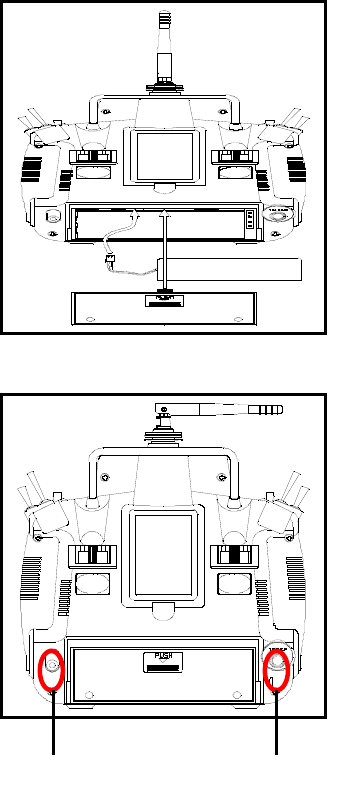
Charging the Eclipse 7 Pro Ni-MH Batteries
Connect the transmitter charging cord into the charging socket
(on the rear of the case, left side) and airborne Ni-MH batteries
to the receiver connector on the charger. Connect the receiver
battery to the charging cord. Plug the charger into a wall socket.
The charger's LEDs should light, indicating charging current is
flowing. The batteries should be left on charge for about 15 hours.
Try to charge the batteries with the charger supplied with your
system exclusively. The use of a fast-charger may damage the
batteries by overheating and dramatically reduce their lifetime.
NOTE: If you need to remove or replace the transmitter battery,
do not pull on its wires to remove it. Instead, gently pull on the
connector's plastic housing where it plugs in to the transmitter.
The battery must be removed to charge it properly with a "peak"
charger.
Operating With A Trainer Cord
An optional training cord is available from your dealer.
The cord may be used to help a beginning pilot learn to f ly easily
by allowing a second transmitter, operated by an experienced
instructor, to be connected to this system.
The instructor may override the beginning pilot at any time to
Bring the model back under safe control.
For training To use the trainer cord:
Set up both the student's and instructor's transmitters to have
identical trim and control motions. If the instructor's transmitter
is on a different frequency than the student's, use the student's
transmitter as the master (held by the instructor) and the other
transmitter should be held by the student.
Collapse the student's antenna, and fully extend the instructor's
antenna. If the student's transmitter has aremovable RF module,
remove it from the transmitter.
The Hitec cord is specifically marked at one end as the "master"
the other end as "student". Plug it accordingly into each transmitter,
with power switched off. The trainer jack is on the back of the
transmitter. Turn the connector until its notches line up and it fits
without having to be forced. Turn on the instructor's transmitter.
DO NOT turn on the student transmitter power. Move the controls on the instructor's transmitter, and
verify each control moves the proper direction. Now verify that the student's trims and control travels
match the instructor's by using the trainer switch (the momentary Trainer switch on the top left of the
transmitter case) and switching back and forth while leaving the control sticks and trims alone,
Charge Jack Trainer Jack
then moving the control sticks.The instructor's transmitter has normal control over the model unless
the trainer switch is pulled, passing control to the student's transmitter. If the student loses control, the
instructor can quickly "take over" by releasing the trainer switch and controlling the model.
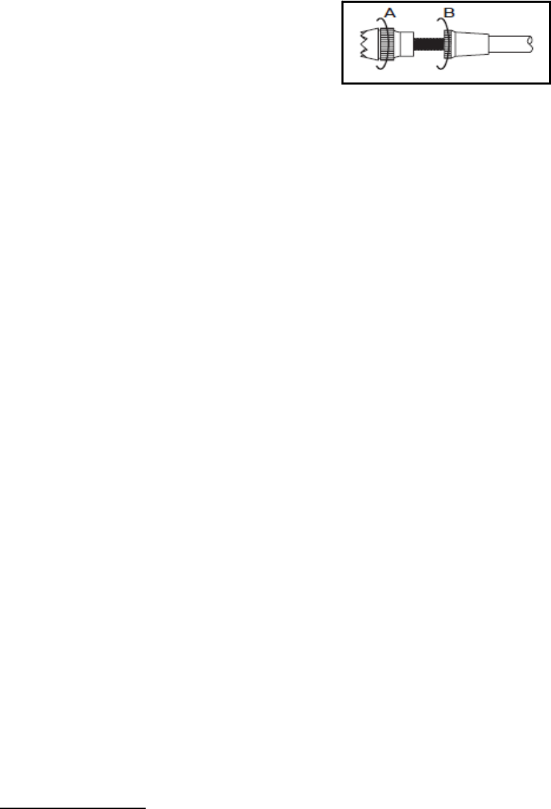
Other Adjustments
Adjustable length control sticks
You may change the length of the control sticks to make your
transmitter more comfortable to hold and operate.
To lengthen or shorten your transmitter sticks, first unlock the
stick tip by holding locking piece B and turning stick tip A
counterclockwise. Next, move the locking piece B up or down
(to lengthen or shorten).
When the length feels comfortable, lock the position by
turning locking piece B counterclockwise.
Stick lever tension adjustment
You may adjust the stick tension of your sticks to provide the "feel" that you like for flying. To adjust
your springs, you'll have to remove the rear case of the transmitter. Using a screwdriver, remove the
six screws that hold the transmitter rear cover into position, and put them in a safe place. Place some
padding under the front of the transmitter and place it face-down on the pad. Gently ease off the
transmitter rear cover and move it to the right side of the transmitter, carefully turning it as you
would turn the page of a book. Now you'll see the view shown. Using a small cross-point screwdriver,
rotate the adjusting screw for each stick for the desired spring tension. The tension increases when
the adjusting screw is turned clockwise, and decreases for counterclockwise motion. When you are
satisfied with the spring tensions, you may close the transmitter. Very carefully reinstall the rear
cover. When the cover is properly in place, tighten the six screws.
Ratchet change
Some pilots, especially those flying helicopters, prefer a "softer" or "smoother" ratchet action on the
throttle stick. An alternate ratchet that provides a smoother ratcheting action is included as an
accessory with your Eclipse 7 system. To change the throttle ratchet, remove the back of the
transmitter case as directed above in the "stick lever tension adjustment" section. Then, unscrew the
ratchet retaining screw, remove the old ratchet, and replace with the new one. Tighten the retaining
screw gently but firmly. Then, replace the transmitter rear cover.
Changing the Eclipse 7 transmitter's mode
If you wish to change the mode of the transmitter, say from Mode 2 to Mode 1, return the radio to
Hitec for conversion. If you don't know what this means, you don't need to worry about it!
Factory Service Repair Information (for U.S.& Canada only)
Please read the warranty card supplied with your system, and return it so your system will be under
warranty. Before you decide to have your system repaired, if there is no apparent physical damage,
read this instruction manual again and check to be sure that you are operating the system as it is
supposed to be operated. If you are still having trouble, pack up your system in its original shipping
materials and send it to the factory or the nearest authorized Hitec R/C Service Center. Be sure to
include a note in your package that describes the trouble in as much detail as possible, including:
Symptoms of the problem in as much detail as you can provide, including any unusual mounting
conditions or equipment orientation A list of items you are sending, and what you want to be repaired.
Your name, address, and telephone number If you have any questions regarding this product, please
consult with Hitec's service center. The address and telephone numbers of our service center is given
below. Telephone inquiries are accepted from 8:00 AM to 4:30 PM weekdays (closed on holidays).
Hitec-RCD, Inc.
12115 Paine St.
Poway, CA 92064
TEL: 1-858-748-6948
FAX: 1-858-748-1767
Web site: http://www.hitecrcd.com
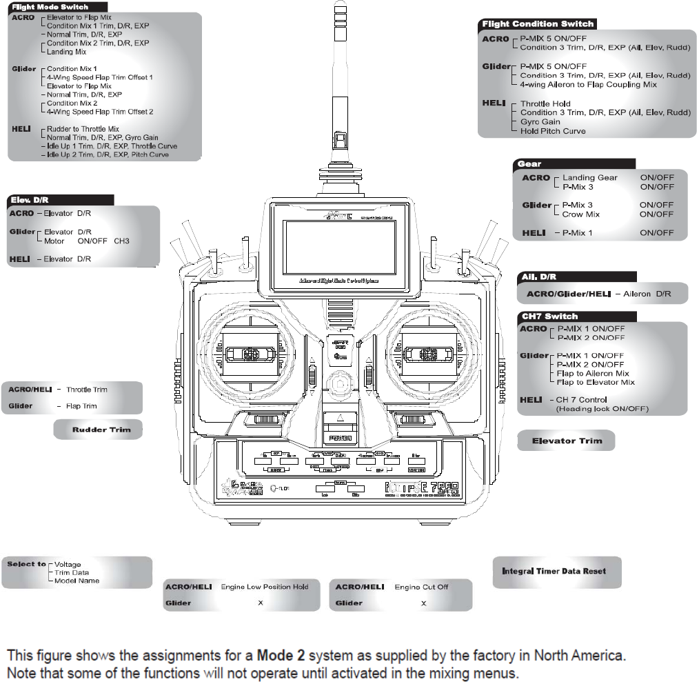
Eclipse 7 Pro “Mode2” Control and Switch Assignments
ECLIPSE 7 PRO MODE 2 TYPE
SWITCH CONFIGURATION LIST FRONT
ECLIPSE 7 PRO MODE 2 TYPE
SWITCH CONFIGURATION LIST REAR
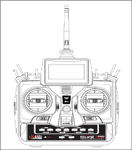
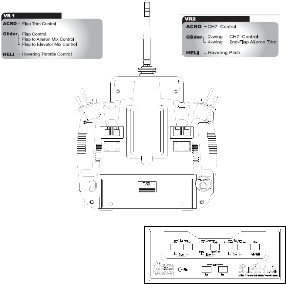
Transmitter Input Buttons
The buttons are used for different things as follows:
1. The Edit/Display Up & Down buttons (1)allow
you to move up and down within the model
menus, and move within the regular display.
select options within a particular function, and
control the timer function.
2. The Data +Increase & -Decrease buttons (3)
allow you to increase or decrease the numerical
settings for a function.
3. The Clear Active/Inhibit button (4)resets numbers, and turns functions on and off.
4. The Engine Lock button (5)holds the throttle channel while other channels may respond to the
transmitter.
5. The Engine Cut button (6)closes the throttle so that you can kill the engine without touching the trim
lever.
You'll learn how to use these buttons in the setup sections that follow
6.the link button Can be used for link process between ECLIPSE 7 PRO to a Optima series receivers,
entering the power down mode for range checks, and the Normal/Scan Mode set-up.
Receiver-Servo Connection List
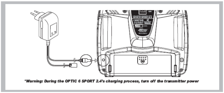
You may run the antenna inside of a non-metallic housing within the fuselage (a plastic outer pushrod
housing works well for this), but range may suffer if the antenna is located near metal pushrods or
cables. Be sure to perform a range check before flying. With the 2.4GHz radio system,
the range check method is different from the conventional frequency radio system.
During the range check period, you should be able to walk away at least 75 feet from the model
without losing control or seeing "jitter" in the servos. The range check should be done with the motor
running and the model should be securely restrained in case of loss of control.
Connectors
Be sure the alignment of a servo or battery connector is correct before inserting it into the receiver. To
remove a connector from the receiver, try to pull on the connector's plastic housing rather than pulling
on the wires. Pulling the wires can ruin the connector pins and break wires.
Using Servo Wire Extensions
If any of your servos are located too far away to plug directly into the receiver (like the aileron servo),
or you need to unplug the servo each time you disassemble the model, use a servo extension cord to
extend the length of the servo lead.
Additional Hitec extension cords of varying lengths are available from your hobby dealer.
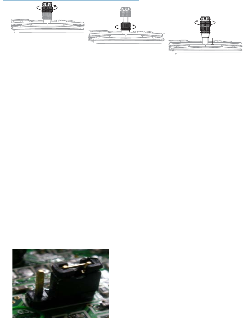
Charge the Batteries
Before we dive into the use of the Optic 5 2.4, let's charge the batteries.
Connect the transmitter charging cord to the transmitter's charging socket
(on the rear of the case, left side).
If your aircraft uses a receiver battery, connect it to the receiver connector on the charging cord.
Plug the charger into a wall socket.
The charger's LEDs should light, indicating charging is in progress.
If either light does not turn on, verify that the transmitter and receiver power switches are OFF.
The batteries should be left on charge for about 15 hours.
Try to charge the batteries with the charger supplied with your system exclusively.
The use of a fast-charger may damage the batteries by overheating and dramatically reduce their
lifetime.
Note
If you need to remove or replace the transmitter battery, do not pull on its wires to remove it.
Instead, gently pull on the connector's plastic housing where it plugs in to the transmitter.
The battery must be removed to charge it properly with a "peak" charger.
Be careful if you do choose to use a field charger on your batteries.
A fast-charger may overcharge the batteries, causing overheating and a premature failure. Never
charge your transmitter or receiver battery at a rate higher than the batteries capacity.
For example, the capacity of your Optic 6 Sport's 7.2 volt NIMH battery is 1300mAh and, therefore,
should not be charged at a rate any higher than 1.3 amps.
Caution: Stop flying and bring back your aircraft and land at once, when your transmitter start beeps
for low battery warning. (L.B.W. activates when battery level hits below 6.6V)
A training cable may be used to help a beginning pilot learn to fly safer by allowing a second
transmitter, operated by an experienced instructor, to be connected to the Optic 6 Sport 2.4 transmitter.
The instructor may override the beginner at any time to bring the model back under safe control. For
training, the transmitter may be connected to another Hitec 2.4GHz system using the Hitec cord part
No. #58320 TRAINER CABLE (between 6 cell transmitter battery systems) or #58321 TRAINER CABLE
FULL PACKAGE (#58320 + Slave DIN + Master DIN) - For use between a 6 cell transmitter battery
system and 8 cell transmitter battery system.
Operating with a Trainer Cord
Note1
To use the trainer system between STEREO Jack Transmitter and STEREO Jack Transmitter
(Needs #58320 between 6 cell Battery Radios)
1) Set up both the student's and instructor's transmitter to have identical trim and control motions.
If the instructor's transmitter is on a different frequency than the student's, use the student's
transmitter as the master transmitter, and the other transmitter as the student's.
2) Turn on the instructor's transmitter and DO NOT turn on the student's transmitter power.
Plug Trainer Cord (#58320 Stereo Jack) accordingly into each transmitter. The trainer jack is on the
back of the transmitter.
Then you can see "MAS MODE" on the LCD screen of Instructor's transmitter and "SLV MODE" on
the Student's transmitter screen.
3) Move the controls on the instructor's transmitter, and verify each control moves the proper direction.
Now verify that the student's trims and control travels match the instructor's by using the trainer
button (the momentary ENG CUT/TRAINER button on the top right of the transmitter case) and
switching on and off while leaving the control sticks and trims alone, then moving the control sticks.
4) The instructor's transmitter has normal control over the model unless the trainer button is pressed,
passing control to the student's transmitter.
If the student loses control, the instructor can quickly "take over" by releasing the trainer button and
then controlling the model.
To use the trainer system between a STEREO Jack Transmitter and a DIN Jack Transmitter.
(Needs trainer cable package #58321 between 6 cell Battery Radio and 8 cell Battery Radio system)
ease read the following instruction carefully for using transmitters with DIN Jack and/or stereo jack for
the trainer system. You will need the Trainer cable full package (#58321).
This full package is consists of a STEREO Jack trainer cable(#58320), Instructor DIN Jack and
Student DIN Jack Adapter.
This package allows the proper connection between a 6 cell battery system radio (ex. Optic 6 Sport
2.4, Aurora 9) and 8 cell battery system radios (ex. Optic 6 2.4 / Eclipse 7 2.4).
Note 2
This section tells you how to connect the transmitters only.
Please read the prior sections for the full information needed to properly operate the trainer cable
system.
Between the Transmitter having a STEREO jack as INSTRUCTOR and Transmitter having DIN jack
as STUDENT.
1) Power on the INSTRUCTORS Transmitter having the STEREO Jack.
2) Plug the STEREO Jack trainer cable (#58320) into the Master, or INSTRUCTORS transmitter.
Note3
You will see "MAS MODE" on LCD screen which means the transmitter is recognized as the
INSTRUCTOR or "Master".
Connect the DIN Jack adapter marked "STUDENT" from the cable package #58320 to the other end
of the stereo connector cable.
This combination enables you to connect the cable to the STUDENT transmitter with a DIN Jack
connector.
Plug the DIN connector into the socket on the STUDENT transmitter.
Finally, power on the STUDENT transmitter. Though it is powered on, the STUDENT transmitter will
not transmit the radio signal as long as the trainer cable is connected properly.
Note4
There is no sign of recognition on the LCD screen of the Transmitter using the DIN jack.
Between the Transmitter having a DIN jack as INSTRUCTOR and a Transmitter having a STEREO
jack as STUDENT.
1) Connect the INSTRUCTOR or DIN Jack adapter marker "Master" with #58320 stereo jack Trainer
cable.
2) Power on the INSTRUCTOR transmitter.
3) Plug the combined trainer cable into the INSTRUCTOR transmitter DIN jack connection.
4) The STUDENT transmitter should be turned off.
5) Plug the trainer cable into the STUDENT transmitter with the stereo jack.
The power to the STUDENT transmitter will turn on automatically and you will see "SLV MODE" on
the LCD screen which means the transmitter is recognized as STUDENT or "Slave".
6) Though the STUDENT transmitter is powered on automatically, it will not transmit a radio signal as
long as the trainer cable is connected properly.
Note5
1) Do NOT turn on the power of the STUDENT transmitter having the STEREO Jack.
Once you plug the trainer cable into the STUDENT Transmitter using the STEREO Jack, it will be
powered on automatically.
2) All Transmitters in the trainer system use their own batteries. Both batteries in both the Instructor
and Student Transmitters should be properly charged and installed when flying in the trainer mode.
3) You may wish to use a simple "contractors cord" knot on the cable to adaptor connection to keep it
from coming "unplugged" when using it. Heat shrink tubing or electrical tape can also be used.
Stick Length Adjustment
Hands come in all sizes so to accommodate everyone we use a two piece stick “top” that can be
adjusted to fit a wide variety of users.
Separate the top from the bottom piece and adjust the top piece to the length required.
Screw the bottom up against the top piece to “jam” lock everything into position.
Stick Lever Tension Adjustment / Mode Change
Stick Lever Tension Adjustment
You may adjust the stick tension of your sticks to provide the "feel" that you like for flying. To adjust
your springs, you'll have to remove the case of the transmitter. Using a screwdriver, remove the six
screws that hold the transmitter's rear cover into position, and put them in a safe place. Now, place
some padding under the front of the transmitter and set it face-down on the pad.
Gently ease off the transmitter's rear cover. Now you'll see the view shown. Use a small cross-point
screwdriver, rotate the adjusting screw for each stick for the desired spring tension.
The tension increases when the adjusting screw is turned clockwise, and decreases for
counterclockwise motion.
Note: Please use M2 (2mm) or 5/64inch Hex key for tension adjustment and mode changes.
When you are satisfied with the spring tensions, you may close the transmitter. Very carefully reinstall
the rear cover. When the cover is properly in place, tighten the six screws.
Change to ‘Mode 1’ Configuration
All Optic 6 Sport 2.4 systems sold in US are in ‘Mode 2’ format. However, you may wish to use Optic 6
Sport in ‘mode 1’ format. There is a menu choice for this option in the Initial Set-Up function menu
described on Page 15.
After selecting ‘Mode 1’ in the Initial Set-Up Menu, you must do the following hardware set-up in order
to change the transmitter
1. Carefully remove the plastic side panels from the transmitter.
2. Remove all the six philips screws from the back of the case.
3. Unscrew a hex screw to remove the Copper Ratchet from where it is located and move it to the
other side.
4. Allocate the “Mode Selection Jumper” to be connected with the other two.
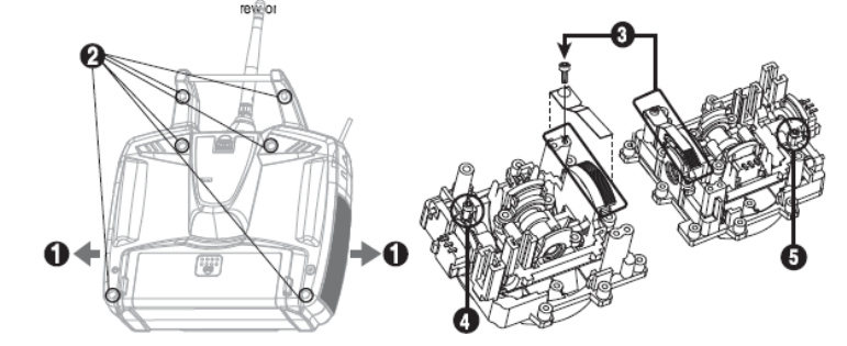
5. Tighten up the tension spring hex screw on the new location, and try control the stick and feel it first
if you like the tension of control stick.
6. Loosen up the tension spring hex screw on the original location.
7. Re-assemble the case.
Flying Safety
To ensure your own safety and the safety of others, please observe the following precautions:
Flying field
We recommend that you fly at a recognized model airplane flying field.
You can find model clubs and fields by asking the nearest hobby dealer, or contacting the Academy of
Model Aeronautics.
Always pay particular attention to the flying field's rules, as well as the presence and location of
spectators, the wind direction, and any obstacles on the field.
Be very careful flying in areas near power lines, tall buildings, or communication facilities as there may
be radio interference in their vicinity.
Once you arrive at the flying field...
Before you fly, perform a range check to confirm your radio system is responding correctly.
To do a range check, Power-up the aircraft and either ask a friend to help hold the aircraft or secure it
somehow.
Walk away from the aircraft until the aircraft "glitches" or you notice intermittent control loss.
Walk back to the aircraft, pacing out the distance.
Note: We want a good range check to be at least 75 feet or so.
When you are ready to fly your model, position the throttle stick or switch to its low speed or off
position.
Then, you may turn on the transmitter power followed by the receiver power.
When you have finished flying, turn off the receiver power first then turn off the transmitter power.
If you do not follow these procedures, the receiver has no information to hold the servos steady and
you may damage your servos or control surfaces or flood your motor.
In case of electric-powered models the motor may unexpectedly turn on and cause a severe injury if
the transmitter is switched off before the receiver.
Before starting the engine, power up the transmitter and receiver, and check to be sure that the
servos follow the movement of the sticks.
If a servo operates abnormally, don't attempt to fly until you determine the cause of the problem.
Before starting the engine, be sure to check that the transmitter model memory is correct for the
chosen model.
While you're getting ready to fly, if you place your transmitter on the ground, be sure that the wind
won't tip it over.
If it is knocked over, the throttle stick may accidentally get moved causing the engine to race
unexpectedly, causing damage or injury to anyone nearby.
Finally, don't fly in the rain! Water or moisture may enter the transmitter through the antenna or stick

openings and cause erratic operation or loss of control.
If you must fly in wet weather during a contest, be sure to protect your transmitter with a plastic bag or
waterproof barrier.
FCC Information to User
This equipment has been tested and found to comply with the limits for a Class B digital device,
pursuant to Part 15 of the FCC Rules. These limits are designed to provide reasonable
protection against harmful interference in a residential installation. This equipment generates,
uses and can radiate radio frequency energy and, if not installed and used in accordance with
the instructions, may cause harmful interference to radio communications. However, there is no
guarantee that interference will not occur in a particular installation. If this equipment does
cause harmful interference to radio or television reception, which can be determined by turning
the equipment off and on, the user is encouraged to try to correct the interference by one of the
following measures:
• Reorient or relocate the receiving antenna.
• Increase the separation between the equipment and receiver.
• Connect the equipment into an outlet on a circuit different from that to which the receiver is
con-nected.
• Consult the dealer or an experienced radio/TV technician for help.
Caution
Modifications not expressly approved by the party responsible for compliance could void the
user’s authority to operate the equipment.
FCC Compliance Information : This device complies with Part 15 of the FCC Rules.
Operation is subject to the following two conditions: (1) This device may not cause harmful
interference, and (2) this device must accept any interference received, including interference
that may cause undesired operation
IMPORTANT NOTE:
FCC RF Radiation Exposure Statement:
This equipment complies with FCC RF radiation exposure limits set forth for an uncontrolled
environment. This equipment should be installed and operated with a minimum distance of 20
centimeters between the radiator and your body.This transmitter must not be co-located or
operating in conjunction with any other antenna or transmitter.
IMPORTANT Safety Instruction:
1) Read these instructions.
2) Keep these instructions.
3) Heed all warnings.
4) Follow all instructions.
5) Do not use this equipment near water.
6) Do not using near any heat sources such as radiators, heat resisters, stove, or other
equipment that produce heat.
CONTACT INFORMATION
Manufacturer Address : 653, YangCheong-Ri, Ochang-Eup, CheongWon-Gun, Chung Buk Province, Korea
To locate in-country Hitec RCD KOREA, INC. distributors of the ECLIPSE 7 PRO 2.4G
please refer to the Hitec RCD KOREA, INC. Website http://www.hitecrcd.co.kr/
These distributor(s) represent local contacts for this product.
CORPORATE HEADQUARTERS:
Hitec RCD KOREA, INC.
653, YangCheong-Ri, Ochang-Eup, CheongWon-Gun, Chung Buk Province, Korea
Tel: 82-43-717-2071
Fax:
82-43-717-2193
Web: http://www.hitecrcd.co.kr/

EUROPEAN UNION “DECLARATION OF CONFORMITY”
DECLARATION OF CONFORMITY
Hitec RCD KOREA, INC.
653, YangCheong-Ri, Ochang-Eup, CheongWon-Gun,
Chung Buk Province, Korea
declare under our sole responsibility that the product(s)
2.4GHz Radio Control System – ECLIPSE 7 PRO 2.4G
to which this declaration relate(s) is in conformance with the following standards:
EN 301 489-1 V1.8.1:2008
EN 301 489-17 V2.1.1 :2009
EN60950-1:2006
EN 300 328 V1.7.1:2006
following the provisions of the 1999/5/EC Directives.