Hitec RCD FLASH8 2.4GHz Radio Control System User Manual
Hitec RCD Inc. 2.4GHz Radio Control System
User Manual
Intro.
Thank you for purchasing the FLASH 8 transmitter. FLASH 8 is composed of diverse features to maximize customer’s R/C experiences. Please read
carefully to become familiar with FLASH 8 under your control. After reading this, please keep this manual for easy reference.
Product Specifications
- Frequency Range : 2.4056GHz~2.4776GHz(Opti-Mini), 2.406GHz~2.480GHz(S.L.T)
- Modulation : Frequency Hopping Spread Spectrum (FHSS)
- Tx Power : Max. 100mW
- Channel : 121Ch(Opti-Mini), 75Ch(S.L.T)
- Operating Temperature : -10℃ ~ +50℃
- Power : 4.4V ~ 7.2V
Features
- Signal communication protocol
: Optima FHSS 2.4GHz receiver is used with the Hitec FHSS 2.4GHz module.
- New Gimbals Stick
: The Gimbal of FLASH 8 is used the four ball bearings for high-end controller so you can feel very smooth stick experience.
Gimbals sense of this soft key will pass to the user’s object immediately then offer the best control touch to you.
- Switch Settings
: User can use the variety switches that given the special features on the FLASH 8 to suit for convenience.
The role of switch is very important to set the variety Mixing function of the plane and FLASH 8 designed on intuitive environment for
setting that function. Please read carefully this manual from the beginning to the end.
- Channel and function settings
: FLASH 8 set to suitable primary channel functions automatically when you select the models such as Helicopter, Airplane and Glider and this
user-friendly features will make you fun while you are using FLASH 8.
- Display RGB LED status
: This function displays the LED status or indicate the Code in progress Set-up.
- Function Button
: Use this button when to combine the OPTIMA receiver and the built-in FHSS 2.4GHz module or to Set normal/scan mode or Power off when check
the range.
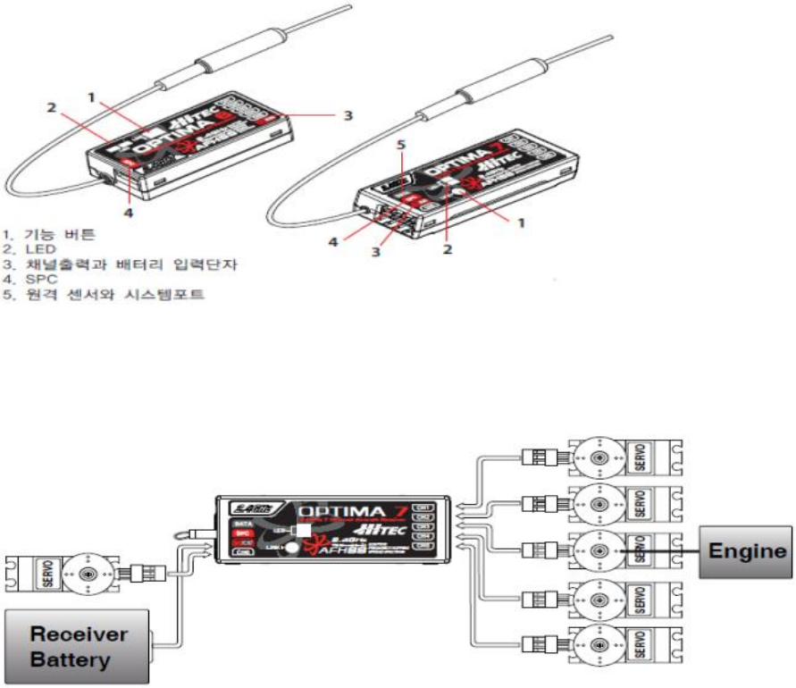
Features of OPTIMA Series Rx
OPTIMA 6, 7 receivers are compatible with built-in FHSS 2.4GHz module of FLASH 8 and They have many necessary functions for the 2-way
communication radio control.
- 2-way communication sensor and System terminal
: The sensor station collect the data that 2-way communication sensor sent and Data is transferred to the FLASH 8 through the data 3pin of
OPTIMA7 receiver. You can upgrade the software of your Tx or send data of your sensor station to the PC if you extra purchase the HPP-22.
- Function Button
: OPTIMA receiver and built-in FHSS 2.4GHz module are used to set Fail-Safe/Hold function.
- Display Dual LED status
: This function displays the LED status or indicate the Code in progress Set-up.
- SPC auxiliary power connection
: SPC auxiliary power connection can supply motor power until 35V to OPTIMA Rx. Please refer to the detailed description about SPC function.
- Channel output and input terminals of batteries
: The OPTIMA is connected batteries, servos, gyro and other equipments.
- Jumper
: A Jumper of Rx is mounted in the factory and It is used to supply power by the general BEC(Battery Eliminator Circuit) of electronic
transmission or 4.8 to 6 volt Ni-MH battery pack or battery Li-PO 2Cell.
(Warning – The Servo ability is different according to the part of regulator capacity and stable power supply of receiver. Please check this
always.)
- Normal / Scan mode selection
: You can select Normal / Scan mode by 2.4GHz signal type..
- Fail-Safe Specifications
: This function is operating servo or peripheral on Fail-Safe status if signal of Tx is quit.
- Low voltage warning function of Rx battery
: OPTIMA Rx is mounted the 2-way function that send the occurred low voltage data of Rx to Tx during the flight.
OPTIMA receiver wiring
Glow engine / Petrol engine / Electric wiring diagram of the Plane.
- The following figure illustrates the battery wiring that is used Li-Po 2Cell or 4.8 ~ 6V Ni-MH.
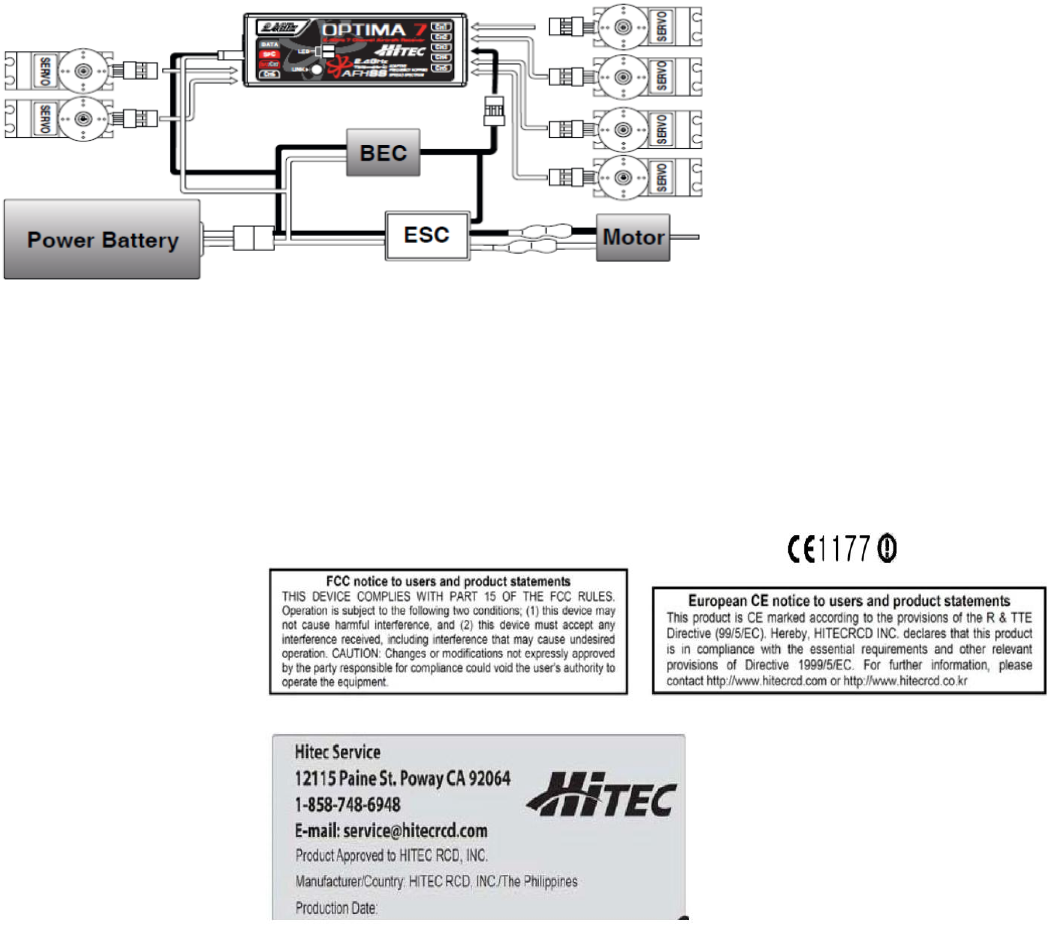
- The following figure illustrates the wiring that BEC supply power to Rx and servo also the Electronic transmission supply power to the motor.
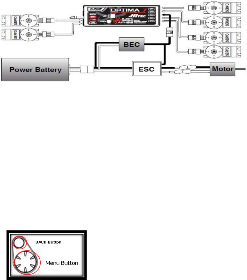
- Use the BEC when servo current consumption exceeds the current that supplied by ESC.
- (Warning – Please following this procedures whenever put the power to the transceiver system.
- Power ON: Power on the Tx first then power on the Rx next.
- Power OFF: Power off the Rx first then power off the Tx next.)
Pre-flight checks
Please put the power to follow above warning order before use the engine or motor. And flight after check that all servos operate smoothly.
Range Check
Please check the range for verifying that transceiver operate normally.
(Warning – Transceiver Pre-set the ID for user’s convenience when it comes from factory. Please follow the procedure below if you extra purchase
OPTIMA Rx due to additional planes.)
How to connect transceivers (ID setting) and set methods
1. Press and hold the Back button and Menu button at the same time then go to the menu screen after turn on the power.
2. Turn the Menu button then go into SPECTRA Menu, then select the type of Rx, then make sure the RGB LED colors changes after BINDING.
3. Please turn on the power while Rx’s LINK button is pressing. Release the LINK button after check that red and green LED of Rx are turned
on. Rx will show you to turn on the red and green LED if Rx operating is normal.
4. Turn off the power of Rx then press the back button of FLASH 8 a few times then go to Main screen.
5. Red LED keeps condition after turn on the Receiver’s power. (LED color may vary depending on the receiver.)
6. Now, you can steer object in normal mode that Tx and Rx are connected.
(Warning – Available LINK range of Tx and Rx is between 45cm and 5M. If LINK cut off more than 1 second because of the external
environment in the Scan Mode or one of transceiver’s power is turned off, you have to turn off both the Tx and Rx then LINK again.)
Transmitter Scan Mode
1. Press and hold the Back button and Menu button at the same time then go to the menu screen after turn on the power of FLASH 8.
2. Turn the Menu button then go into SPECTRA Menu then select the type of Rx then Scanning.
3. Look for the cleanest frequency in the complex environment.
4. Process again after complete to BINDING of the transceiver.
Fail safe and hold mode
When Rx signal take effect on external influence if you set the Fail - safe mode, the servo will go to Fail–safe position you stored already. The servo
will turn off the power for 1 second in hold time if you didn’t enable the Fail–safe mode. Then the servo will keep no-load condition and move to the
position that is ordered last time until it detects a normal signal again. Always, the Fail-safe mode must be enable for safe flight and the Fail-safe
mode is required safe flight status like the engine idling, the motor stop, extended air brake, etc.
- Fail-safe set-up
1. Please check the transmission system works perfectly after power on the transceiver.
2. The red LED will turn off after press and hold Rx’s LINK button for 6 seconds then the red and green LED will flash in turn after release a
LINK button then you must move all of sticks to the Fail-safe position then fix in 5 seconds,
3. The red and green LED will flash in turn faster then only red LED will turn on lastly. You must fix sticks in the Fail-safe position until this
status.
4. Complete to save the Fail-safe position.
5. Power off the Rx first then power off the Tx next.
6. Enable the transmission system then turn off the transceiver.
7. Check the servo move to the Fail-safe position.
- Fail-safe Setting TEST
1. The flight move to the any place that is not the Fail-safe setting.
2. It is the normal Fail-safe setting if the servo moves to the Fail-safe position you set lastly after you turn off the Tx.
- The way to re-enable the Hold mode in Fail-safe mode.
1. Turn on Tx then check the transmission system works perfectly to the model.
2. The red LED will turn off after press and hold Rx’s LINK button for 6 seconds then the red and green LED will flash in turn after release a
LINK button
3. Press the LINK button one more time when the red and green LED flash in turn.
4. The Fail-safe mode is disabled and The Hold mode is enabled.
5. Power off the Rx first then power off the Tx next.
6. You can use the transceiver in the Hold mode.
(Warning – The Fail-safe setting will delete you set lastly if the Fail-safe mode is disabled. Always check the Fail-safe mode work normally
before you turn on the engine or motor.)
Transmission Range Checks.
Always, It is very important to check the transceiver’s signal and range are normal or not before flight. Unlike FM/PPM and PCM, It is impossible to
verify the range of transmission to fold the antenna because the 2.4GHz antenna of Transceiver is short and fixed. Hitec 2.4GHz system can reduce the
signal strength of transmitter by force to use the Power-down mode. The Power-down mode reduces the range up to 30 meters. Please check the
minimum distance more than 30 meters between the Tx and Rx then make sure the Tx and Rx work normally in the Power-down time.

How work the Power-down mode?
1. Turn of the power of FLASH 8 then Press and hold the back and menu button at the same time then go to the Menu screen.
2. Turn the menu button then go into the SPECTRA menu. Select the Yes after press the menu button on the Range check.
3. Check the minimum distance more than 30 meters between the Tx and Rx then make sure the Tx and Rx work normally in the Power-down
time.
4. Press the menu button if you want to change to the Normal mode.
2-way communication wireless remote control system
Receivers of Hitec FLASH 8 and OPTIMA series built in the 2-way communication model to detect the voltage level automatically after Power on.
And there are GPS, temperature, oil flow and RPM sensors in 2-way communication product (However, OPIMA6 can not mount 2-way communication
Option sensor.)
If you want to get more new information please refer the Hitec web site. www.hitecrcd.co.kr
Low Battery Warning
- The battery voltage is normal, there is no change in the module.
- The battery voltage is low, the alarm sounds. Please check the battery voltage immediately if you here a beep in flight.
SPC System
You can enjoy this SPC system only in Hitec Products. This auxiliary power system will supply the battery power to the SPC directly so the receiver
can always keep stable status in emergency situation. The SPC can be supplied up to 35 volts directly from the power battery. Never supply the power
to the Main Battery terminal of Rx. This is a description about the auxiliary power system that to supply power to the SPC terminal of the OPTIMA
receiver. Usually almost Servos will burn if the Main Battery terminal is supplied 35 volts.
( Note – Some of the High voltage servos need 7.4 volts in Hitec Products. Therefore you need 4 cell Ni-MH or 2 cell Li-Po receiver batteries and
Rectifier device for setting. SPC System is applied partially to the Hitec 2-way communication wireless remote control system.
If you want to get more information about 2-way communication products, please refer the Hitec web site. www.hitecrcd.co.kr )
Warnings and Precautions
- Don’t steer this in the busy street.
- Don’t steer this in the rain and on the standing water.
- Don’t steer this after drink alcohol.
- Always check the remaining battery power.
- Always power on the Tx first then power on the Rx next to prevent failure.
WARNING & SAFETY INFORMATION 7
WARNING & SAFETY INFORMATION
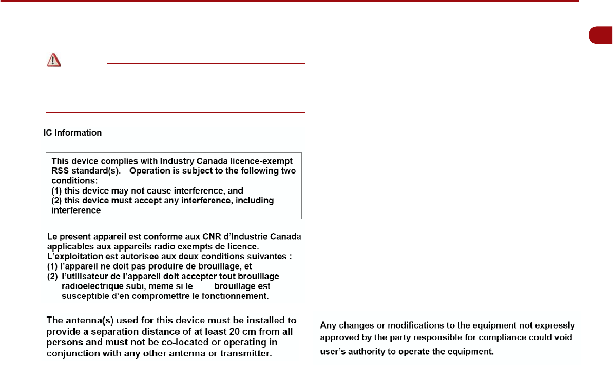
Safety Symbols
FCC Information
6JKUFGXKEGEQORNKGUYKVJRCTVQHVJG(%%4WNGU1RGTCVKQPKUUWDLGEV
VQVJGHQNNQYKPIVYQEQPFKVKQPU
6JKUFGXKEGOC[PQVECWUGJCTOHWNKPVGTHGTGPEGCPF
6JKU FGXKEGOWUVCEEGRVCP[KPVGTHGTGPEGTGEGKXGFKPENWFKPI
KPVGTHGTGPEGVJCVOC[ECWUGWPFGUKTGFQRGTCVKQP
FCC notification to users
6JKUGSWKROGPVJCUDGGPVGUVGFCPFHQWPFVQEQORN[YKVJVJGNKOKVUHQTC
%.#55 $ FKIKVCN FGXKEG RWTUWCPV VQ 2CTV QH VJG (%% 4WNGU 6JGUG
NKOKVUCTGFGUKIPGFVQRTQXKFGTGCUQPCDNGRTQVGEVKQPCICKPUVJCTOHWN
KPVGTHGTGPEG YJGPVJGGSWKROGPVKUQRGTCVGFKPCEQOOGTEKCN
GPXKTQPOGPV 6JKU GSWKROGPV IGPGTCVGU WUGU CPF ECP TCFKCVG TCFKQ
HTGSWGPE[GPGTI[ CPF KH PQVKPUVCNNGF CPF WUGF KPCEEQTFCPEG YKVJ VJG
KPUVTWEVKQPU OC[ ECWUG JCTOHWN KPVGTHGTGPEG VQ TCFKQ EQOOWPKECVKQPU
*QYGXGTVJGTG KUPQ IWCTCPVGGVJCVKPVGTHGTGPEGYKNNPQV QEEWT KP C
RCTVKEWNCTKPUVCNNCVKQP+HVJKUGSWKROGPVFQGUECWUGJCTOHWNKPVGTHGTGPEG
VJG WUGT KU GPEQWTCIGF VQ VT[ VQ EQTTGEV VJG KPVGTHGTGPEG D[ EQPUWNVKPI
YKVJC-+#FGCNGTQTCPGZRGTKGPEGFVGEJPKEKCPHQTVGEJPKECNCUUKUVCPEG
㿋#
9JGPGPEQWPVGTKPIVJKUU[ODQNKPVJGOCPWCN[QWOWUVHQNNQYVJGUG
TGEQOOGPFCVKQPUVQCXQKFKTTGRCTCDNGFCOCIGVQ[QWTECTU[UVGOQT
EQPPGEVGFFGXKEGUQTVQCXQKFCEEKFGPVUYKVJKPLWTKGUQTFGCVJ
㿋#
9JGPGPEQWPVGTKPI VJKUU[ODQN KPVJGOCPWCN[QWOWUV DGXGT[
ECTGHWNCPFHQNNQYVJGTGEQOOGPFCVKQPUVQCXQKFFCOCIGVQ[QWTECT
U[UVGOQTEQPPGEVGFFGXKEGUQTVQCXQKFKPLWT[
㿋#
+PHQTOCVKQPYJKEJ[QWOWUVDGCYCTGQHQTTGEQOOGPFCVKQPUHQT[QWT
EQPXGPKGPEGCPFHQTQRVKOCNQRGTCVKQPQH[QWTU[UVGO
Note
Caution
Warning