Hitec RCD HFMS-CAR-75 REMOTE CONTROL - TRANSMITTER User Manual Car GB2
Hitec RCD Inc. REMOTE CONTROL - TRANSMITTER Car GB2
UserManual.wiki
>
Hitec RCD
>
HFMS CAR 75 User Manual
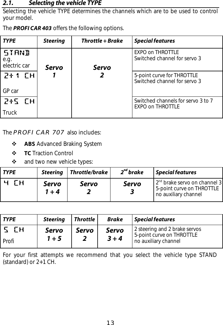
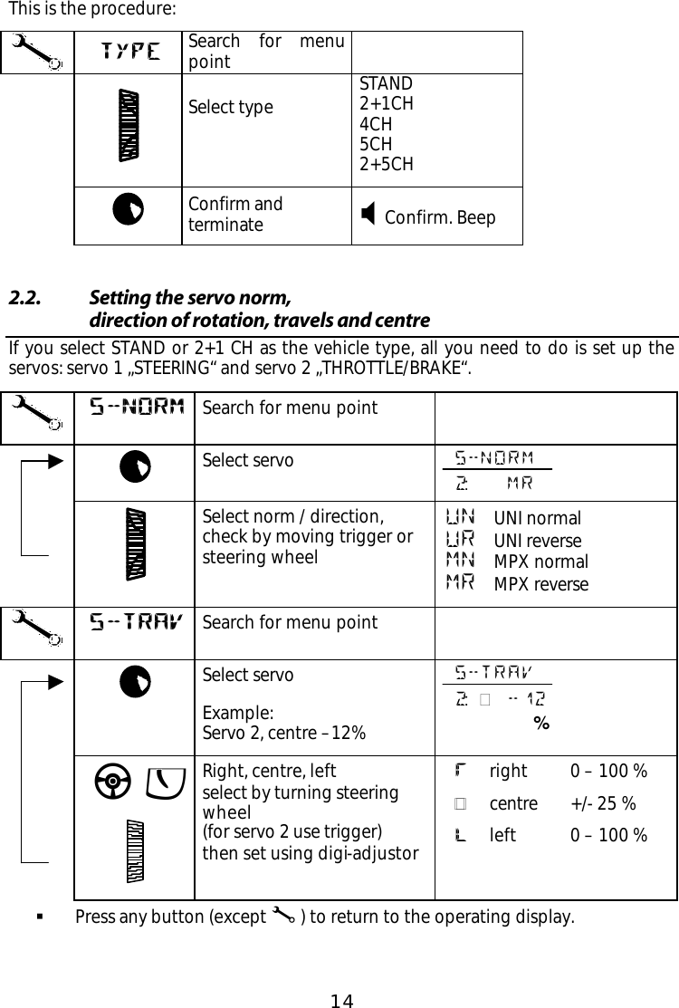
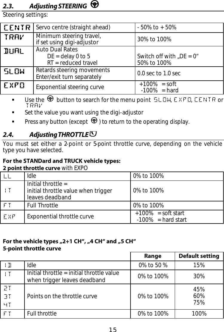
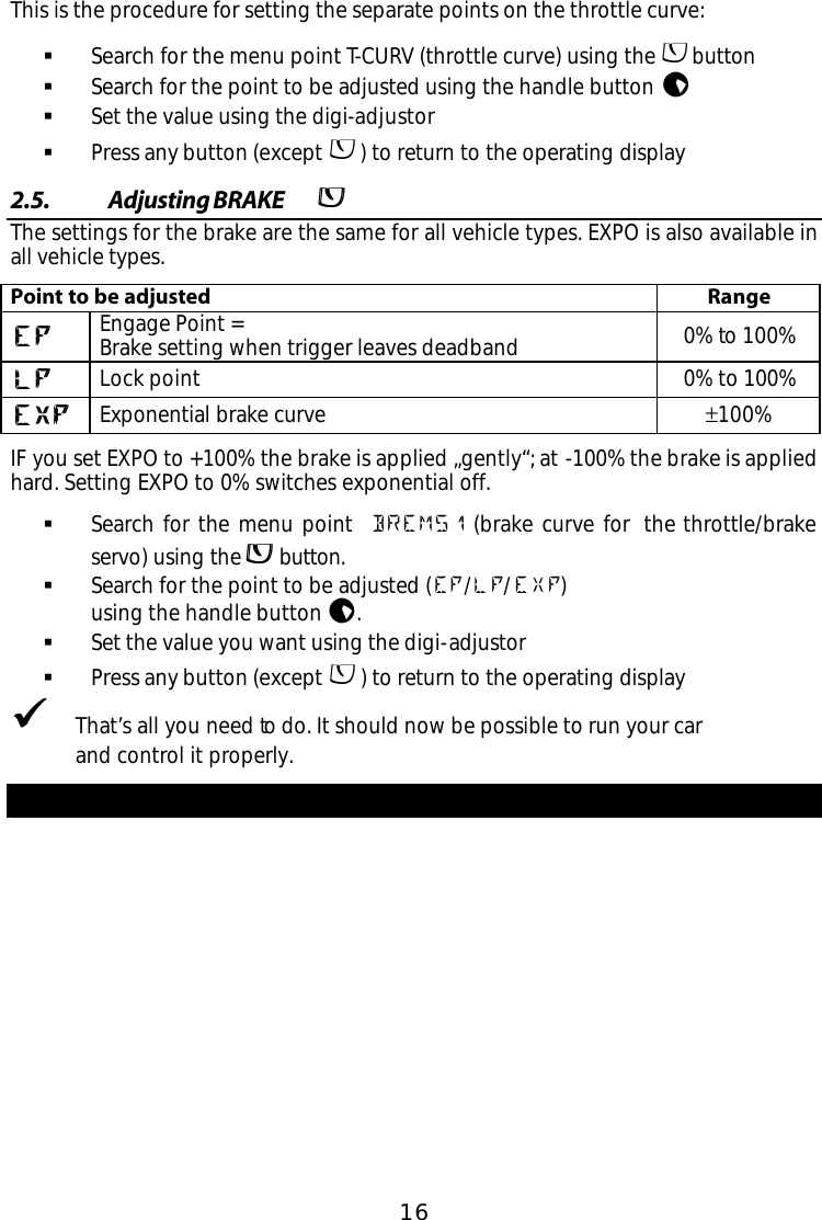
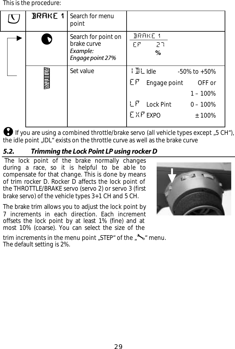
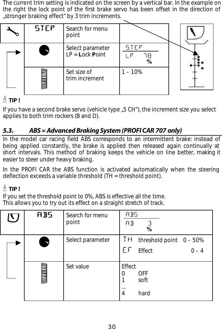
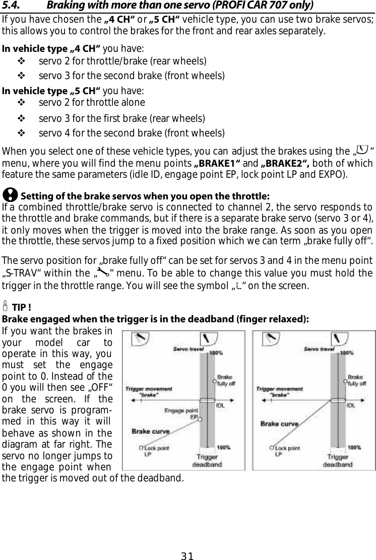
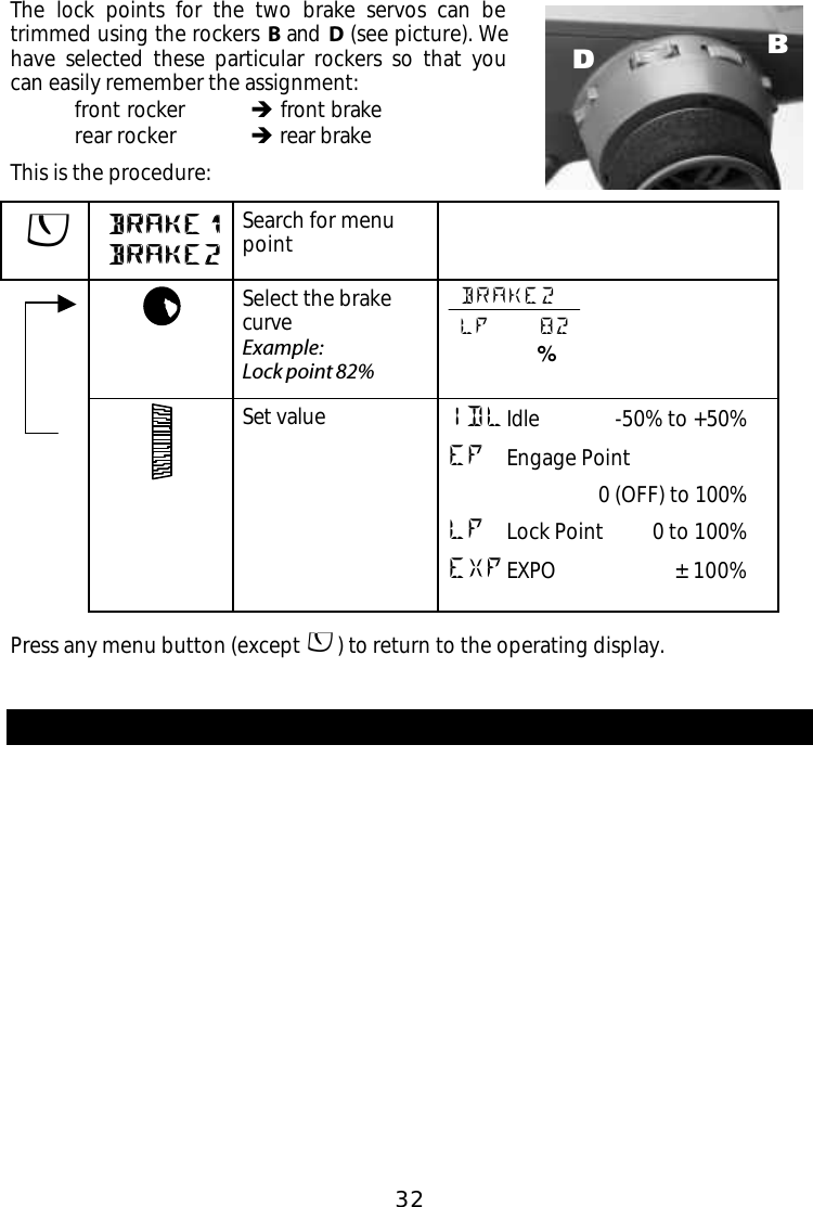
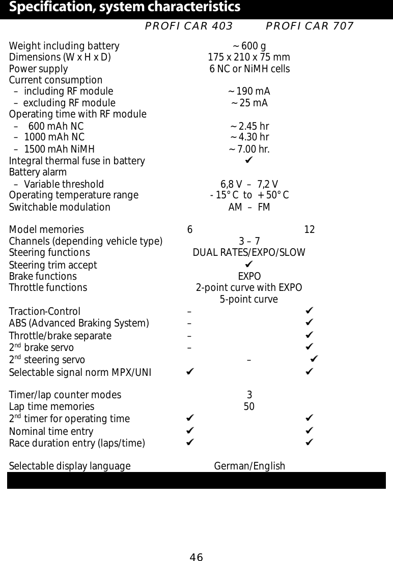
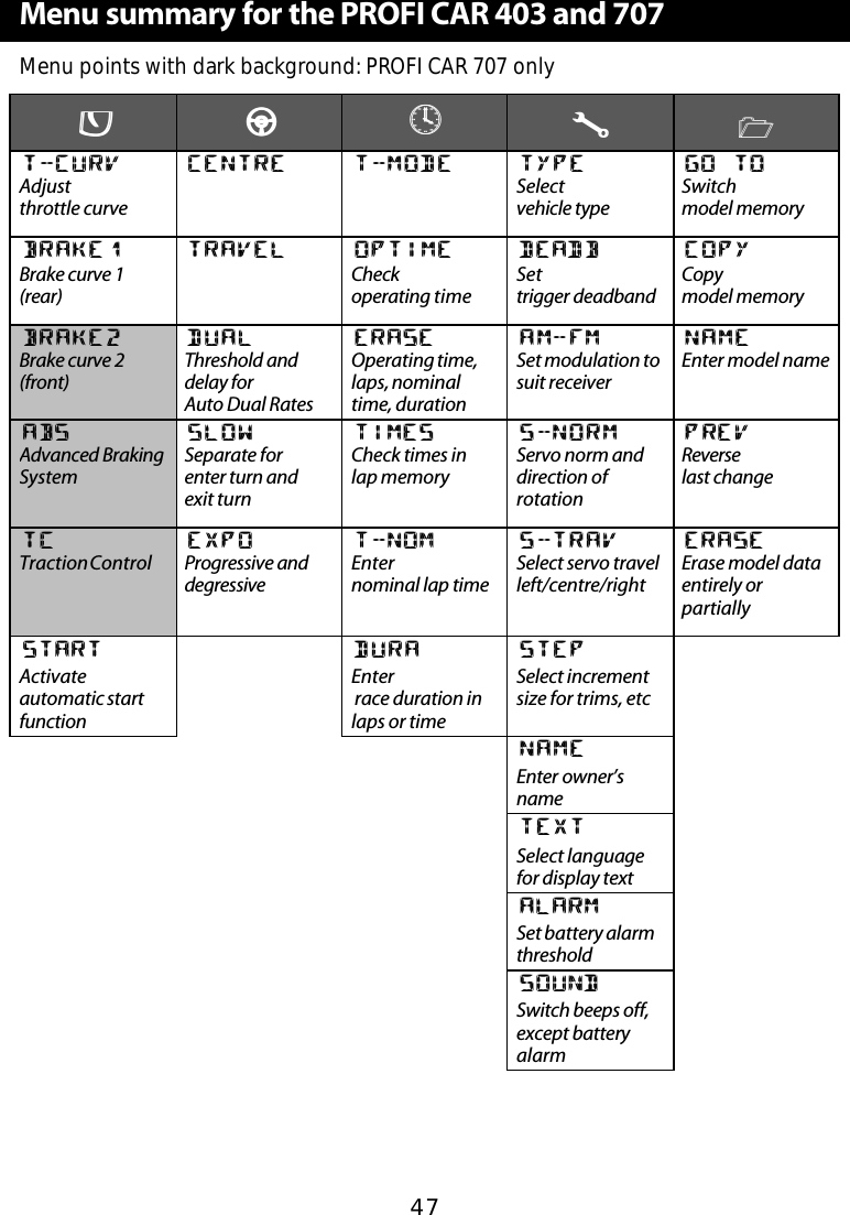
USERS MANUAL
Navigation menu
Upload a User Manual
Namespaces
Wiki Guide
HTML
PDF
Info
Views
User Manual
Discussion / Help
Navigation