Hitec RCD LITE4 2.4GHz RADIO CONTROL SYSTEM User Manual LITE4 Manual
Hitec RCD Inc. 2.4GHz RADIO CONTROL SYSTEM LITE4 Manual
Users Manual
Instruction Manual

2
Thank you for purchasing the LITE4 2.4 digital proportional radio control system.
LITE4 2.4 is easy to use and utilizes the latest in solid-state components for unsurpassed reliability
and performance.
It is important that you read and understand this manual before you attempt to operate your system.
*NOTE : LITE4 2.4 is Compatible With all Minima Series Receivers. (Not Compatible With Optima Series Receivers)
Introduction
Introduction
Table of Contents
1. Transmitter
2. Battery Installation
3. Operation
4. Set-up and Use of LITE4 2.4
5. Precautions
6. Mode Change
7. Service & Support
Page 2.
Page 3.
Page 4.
Page 5.
Page 6.
Page 7.
Page 8.
Page 10.
Page 11.
Page 12.
Page 13.
Page 14.
Page 15.
Table of Contents
LITE4 2.4 Instruction Manual
A. Features
B. Layout
C. Specifications
D. Servo Reversing
E. Control Stick Adjustment
F. Stick Lever Tension Adjustment
G. Trim Levers
H. Reading the LED Battery Indicator
A. Connection Diagrams
B. Equipment Mounting
C. Vibration and Water
D. Antenna Installation (Minima 6S)
E. Operating with a Trainer Cord
A. ID-Set up A.K.A, Link or Bind
B. SmartScan Function
C. Range Check Function
D. Min. and Max. Range for Binding
E. Receiver-Servo Connection List
F. Trim Adjustment
G. ELVN (Elevon Mix)
H. S. REV (Servo Reverse)
I. V.TAIL (V-Tail)
B. Layout
3
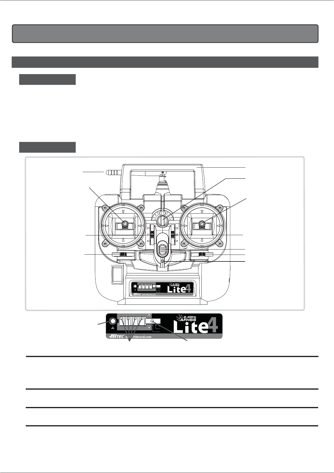
1. TRANSMITTER
- Ergonomically designed 4 channel 2.4GHz(AFHSS) transmitter.
- High quality precision gimbals with adjustable stick length and tension.
- Servo reversing on all channels.
- V-tail and Elevon Mixing
- Trainer system. (Slave mode only)
- Dry battery pack for 4cells for Alkaline battery
- Easy to read 1 LED battery indicators.
- SIC (Simulator Interface Cable) Compatible
FRONT
Handle
LED indicator
Aileron trim
Power switch
Elevator trim
Aileron/
Elevator stick
in MODE II
Neck-strap
connector
Transmitter
antenna
Throttle/Rudder stick
in MODE II
Throttle trim
Rudder trim
LITE4 2.4 Instruction Manual
The Link button can be used for the Link (ID setting) process between the LITE 4 2.4 radio and Hitec minima receiver, entering the power down mode
for range check, activating SmartScan function. The LED indicator shows current working status of the radio with red lights.
For more detailed information, please read pages 10 and 11.
"LINK" button and LED Indicator
The Mixing switch is used for mixing the function of servos with different wing types. ( V-TAIL and ELEVON )
"Mixing ( V-TAIL and ELEVON )" slide switch
The REV switch is used for reversing the direction of the servos.
"REV (Servo Reverse)” slide switch
When the transmitter battery power descends to 4.4v or lower, Red color LED will be blinking.
"Low Battery Warning”
Link
V-TAIL
OFF
ELEVON
CH1 CH2 CH3 CH4
REV
NOR
2.4GHz 4 Channel Aircraft Radio
LINK
Button
REV (Servo Reverse)”slide switch (Mixing V-TAIL and ELEVON)”slide switch
Link
V-TAIL
OFF
ELEVON
CH1 CH2 CH3 CH4
REV
NOR
2.4GHz 4 Channel Aircraft Radio
A. Features
- Power supply : 6V 4cell Dry battery
- Current drain : 100mA
- Output power : 100mw
- Modulation : 2.4G AFHSS Single Directional
- LITE4 2.4 transmitter is equipped with servo reversing on all channels.
- If you need to change travel direction of rotation, open the battery case and
move the servo reversing switch.
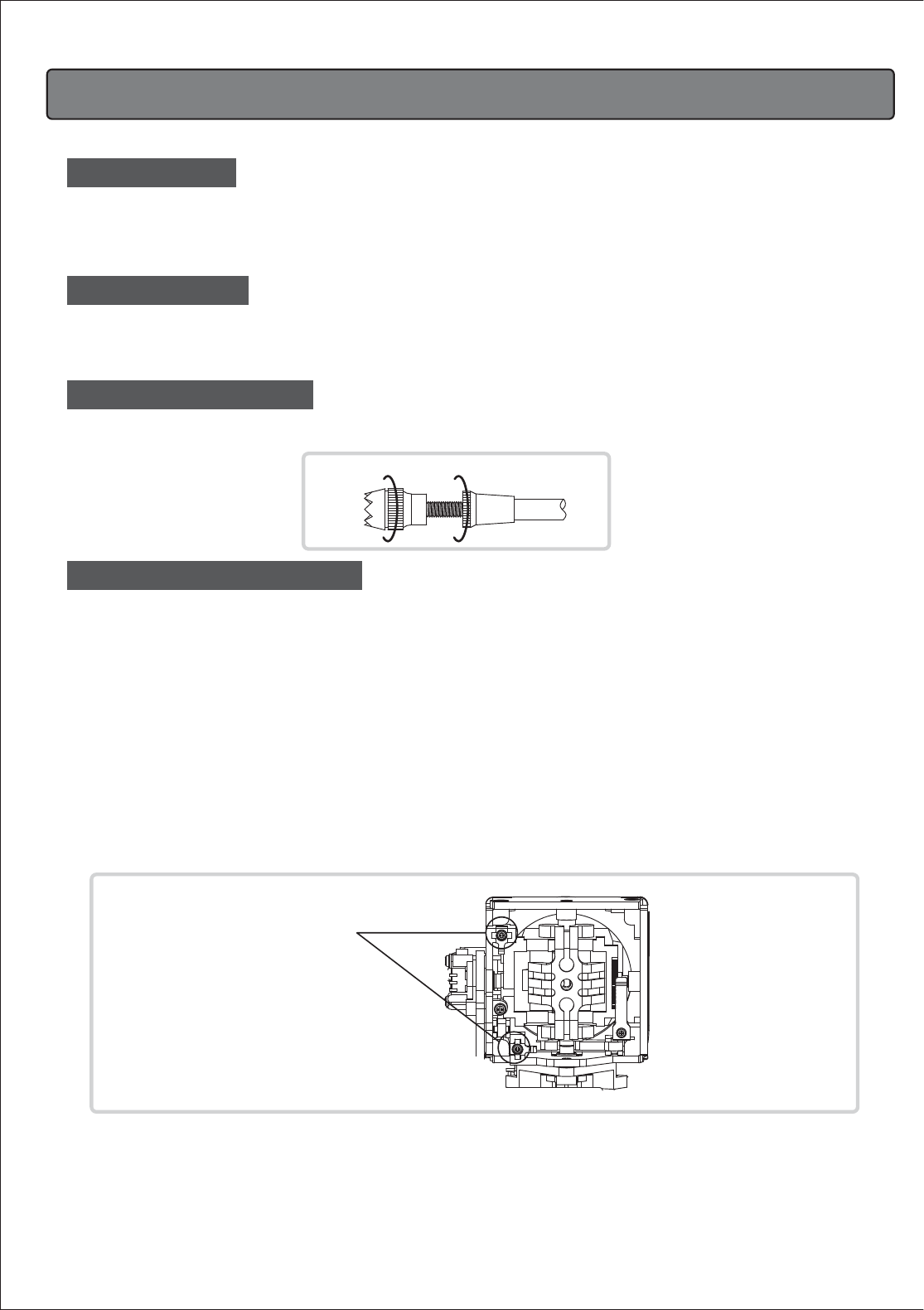
- The unique open-stick assembly provides fully adjustable stick tension to adjust
the feel of the sticks in your hands.
- You may adjust the stick tension of your sticks to provide the feel that you like for flying.
To adjust your springs, you'll have to remove the rear case of the transmitter.
Using a screwdriver, remove the six screws that hold the transmitter's rear cover into position,
and put them in a safe place. Gently ease off the transmitter's rear cover and move it to the
under side of the transmitter, carefully turning it as you would turn the page of a book.
Now you'll see the view shown in the illustration.
Using a small Philips screwdriver, rotate the adjusting screw for each stick for the desired spring tension.
The tension increases when the adjusting screw is turned clockwise,
and decreases for counterclockwise motion.
When you are satisfied with the spring tensions, you may close the transmitter.
Very carefully reinstall the rear cover. When the cover is properly in place, tighten the six screws.
- The length of the non-slip control sticks can be adjusted to suit the requirements of the user.
AB
LITE4 2.4 Lever Tension
Tension adjusting
screw
4
LITE4 2.4 Instruction Manual
C. Specifications
D. Servo Reversing
E. Control Stick Adjustment
F. Stick Lever Tension Adjustment
- The trim levers associated with each control stick are used to correct or (trim-out) the
tracking of the aircraft.
- (Caution) Make sure the trims will move the surface past neutral when moved to their extremes.
This will assure you have adequate trim control.
- After your plane's first test flight, note the positions of the control surfaces that required trim.
Next, center the trims and turn the receiver off. Now adjust the control linkage on the plane
so the surfaces are in the same position before the trim levers were re-centered.
- Turn on the radio and receiver and recheck the control surfaces to ensure that all
the corrections were applied in the proper direction.
-There is one indicator lights on the face of the radio marked High and Low (blinking).
-These relate to the condition of your transmitter battery and the other setups.
Please pay attention to these LED lights and stop flying when the LED light is blinking.
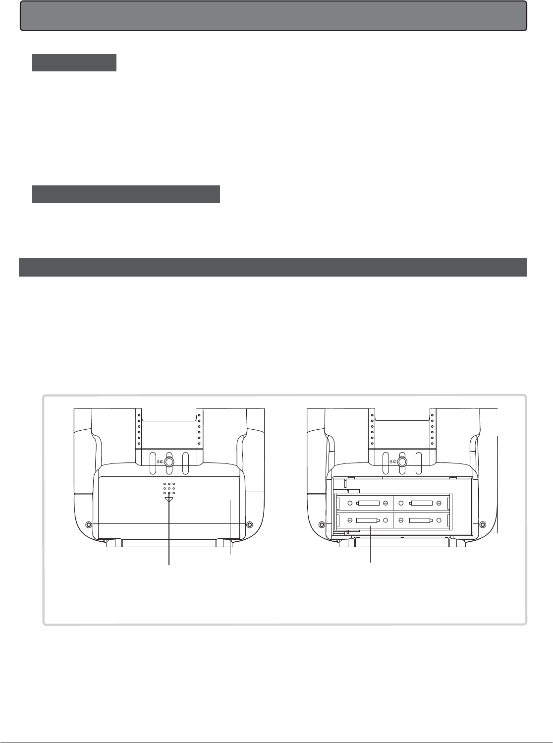
2. BATTERY INSTALLATION
- The transmitter requires four and the receiver battery pack needs four AA size batteries.
These can be Alkaline cells
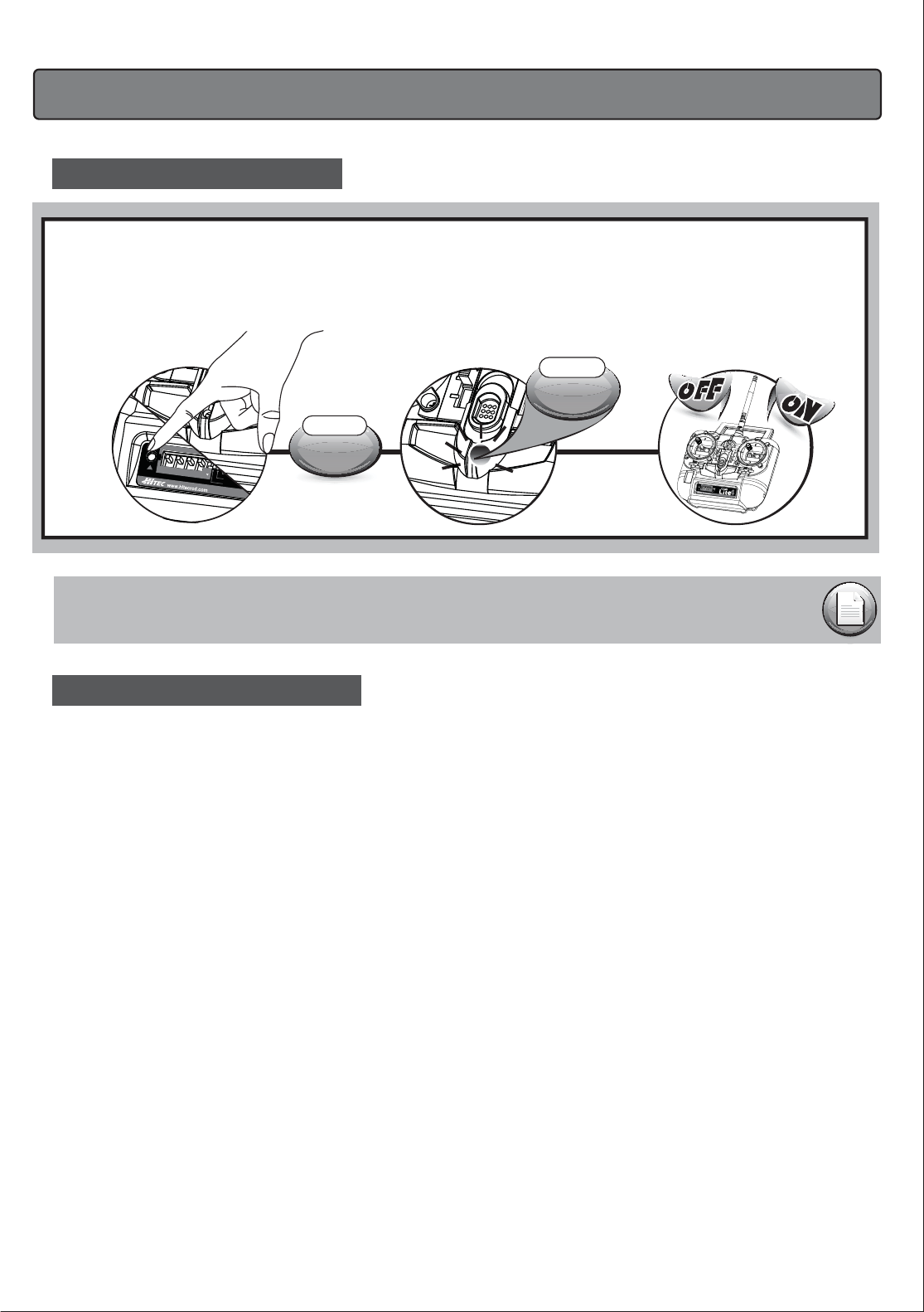
- When loading the batteries, make sure the receiver and transmitter switches are in the "off" position.
- Open the battery door in the back of the transmitter by pressing the tab on the
bottom of the battery door and lifting up.
- Load batteries into the appropriate slots, taking care to install according to the
proper polarity.
- Replace the battery door and turn the power "on".
5
BATTERY COVER
4 AA SIZE BATTERY.BE
CAREFUL TO LOAD RIGHT
DIRECTION OF BATTERIES (+ -)
TO OPEN THE BATTERY COVER
OF THE LITE4 2.4 YOU NEED TO
PRESS THIS AND PUSH IT DOWNWARD.
LITE4 2.4 Instruction Manual
G. Trim Levers
H. Reading the LED Battery Indicator
3. Operation
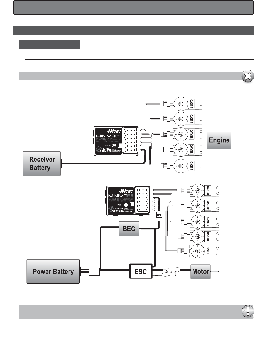
Follow this connection diagram when using a dedicated 4.8 to 6.0V NiMH battery pack.
Warning : Verify your servos are rated for use with higher voltage(7.4V) batteries or a regulator.
Glow, Gas, Nitro or Electric-Powered Aircraft Using a Separate Receiver Battery.
2.4GHz 6 Channel
Aircraft Receiver
6
Optional BEC shown in diagram. It is recommended to use a large capacity BEC when a number of high torque
servos are used and power requirements exceed that which the ESC provides.
2.4GHz 6 Channel
Aircraft Receiver
LITE4 2.4 Instruction Manual
A. Connection Diagrams
Mounting
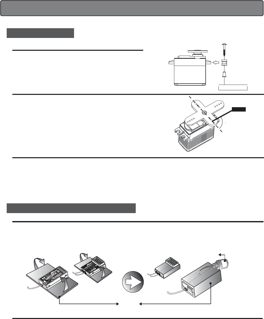
B. Equipment Mounting
When you mount each servo, use the supplied rubber grommets and insert an
eyelet up through the bottom. Be sure not to over tighten the screws.
If any portion of the servo case directly contacts the fuselage or the servo rails,
the rubber grommets will not be able to attenuate vibration, which can lead to
mechanical wear and possible servo failure.
Servo Throw
Factory Repair Service Information
Once you have installed the servos, operate each one over its full travel and
check that the pushrod and output arms do not bind or collide with each other,
even at extreme trim settings.
Check to see that each control linkage does not require undue force to move
(if you hear a servo buzzing when there is no transmitter control motion,
most likely there is too much friction in the control or pushrod).
Even though the servo will tolerate loads like this, they will drain the battery pack
much more rapidly.
Please read the warranty card supplied with your system and return it. Before you decide to have your system repaired, if there is no apparent physical
damage, read this instruction manual again and check to be sure that you are operating the system as it was designed to be operated.
If you are still having trouble, pack up your system in its original shipping materials and send it to the nearest authorized Hitec R/C Service Center.
Be sure to include a note in your package that describes the trouble in as much detail as possible, including: symptoms of the problem in as much detail
as you can provide, including any unusual mounting conditions or equipment orientation, a list of items you are sending, and what you want to be repaired.
Make sure you also provide your name, address and telephone number.
Pushrod
90
Vibration and Water
C. Vibration and Water (OPTIMA & MINIMA Series)
The receiver contains precision electronic parts. Be sure to avoid vibration, shock, and temperature extremes.
For protection, wrap the receiver in the "Flight Preserver" foam rubber, or use some other vibration-absorbing materials.
If you are flying near bodies of water, it's also a good idea to protect the receiver by placing it in a plastic bag and securing the open end of the bag with a
rubber band before wrapping it with foam. If you accidentally get moisture inside the receiver, you may experience intermittent operation or a possible crash.
Switch Harness Installation
When you are ready to install the receiver's switch harness, remove the switch cover and use it as a template to cut screw holes and a rectangular hole
slightly larger than the full stroke of the switch.
Choose a switch location on the opposite side of the fuselage from the engine exhaust, and choose a location where it can't be inadvertently turned on
or off during handling or storage. Install the switch so that it moves without restriction and "snaps" from ON to OFF and vice versa.
Sponge Pad
Cyanoacrylate
or or
2.4GHz 6 Channel
Aircraft Receiver
7
LITE4 2.4 Instruction Manual
NOTE
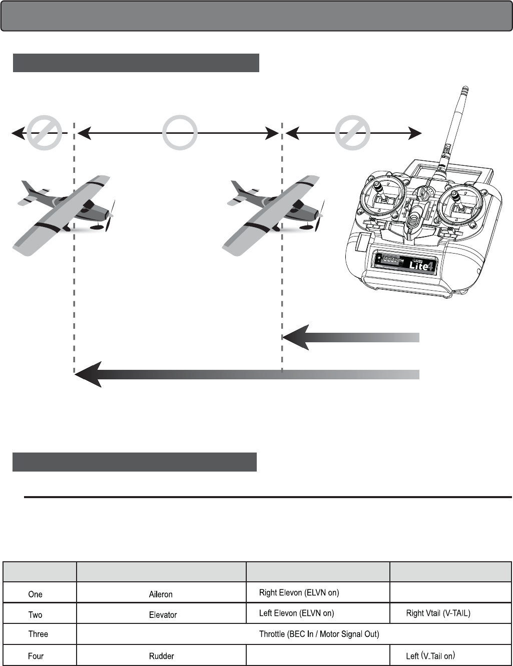
*Detailed range check mothod can be found on page 19. During the range check period, you should be able
to walk away at least 75 feet from the model without losing control or seeing "jitter" in the servos.
The range check should be done with the motor running and the model should be securely restrained in
case of loss of control.
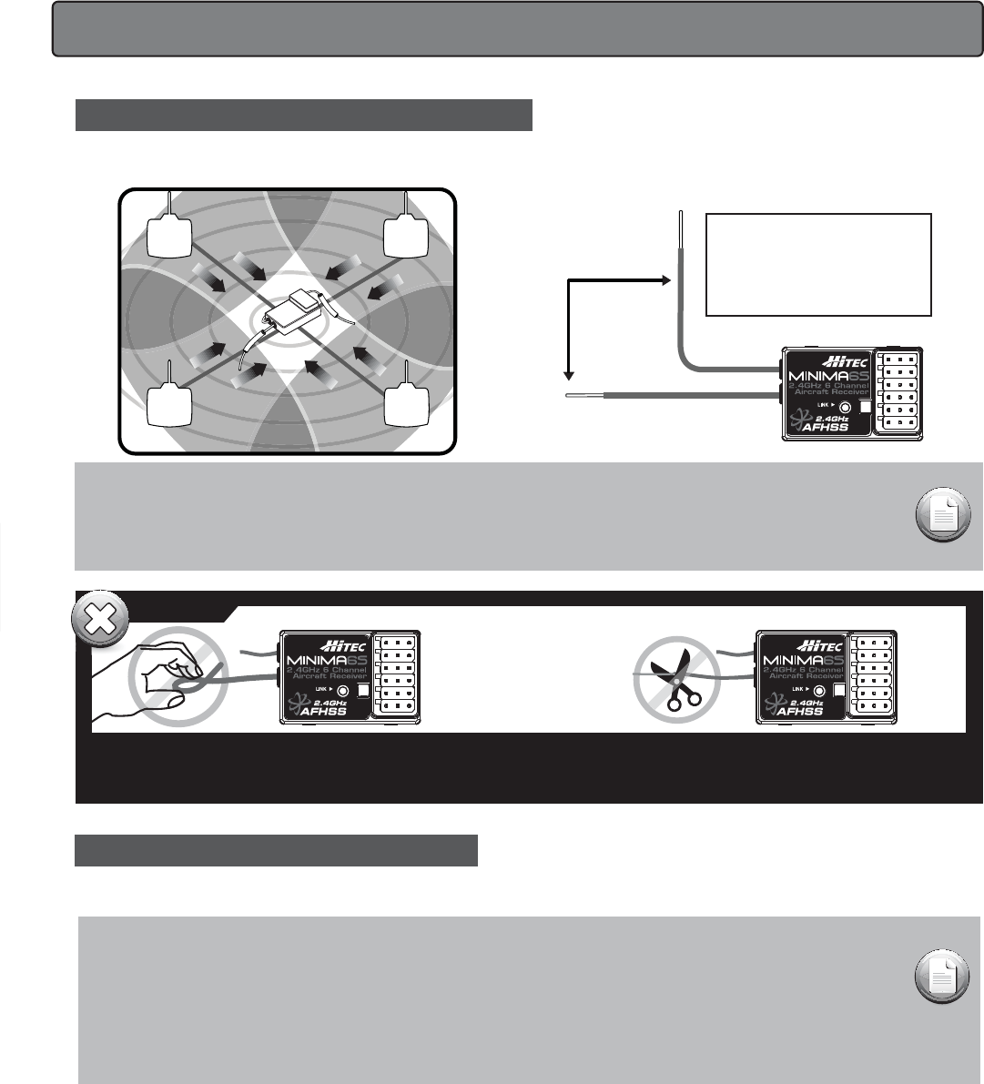
D. Antenna Installation (MINIMA 6S)
Never cut the antenna, such behavior will seriously reduce
the reception range.
Never pinch or bend the antenna, such behavior will cause
serious damage to the antenna.
Changing the length of the antenna reduces range.
Warnings
The Minima 6S antenna system is made for high directivity consisting of two antennas. In order to maximize the functions of the
Minimas, please install as shown below.
TX
TX TX
TX
RX
90˚Recommended installation
method to optimize
receiver performance
1. To use the trainer system between STEREO Jack Transmitter and STEREO Jack Transmitter (Needs #58320 between 6-cell and 4 cellbattery radios).
1) Set up both the student's and instructor's transmitter to have identical trim and control motions. If the instructor's transmitter is on a different
frequency than the student's, use the student's transmitter as the master transmitter, and the other transmitter as the student's.
2) Turn on the instructor's transmitter and DO NOT turn on the student's transmitter power.
Plug Trainer Cord (#58320 Stereo Jack) accordingly into each transmitter. The trainer jack is on the back of the transmitter.
3) Move the controls on the instructor's transmitter, and verify each control moves the proper direction. Now verify that the student's trims and control
travels match the instructor's by switching the trainer button on and off while leaving the control sticks and trims alone then move the control sticks.
4) The instructor's transmitter has normal control over the model unless the trainer button is pressed, passing control to the student's transmitter.
If the student loses control, the instructor can quickly "take over" by releasing the trainer button and then controlling the model.
NOTE:
1. WHEN USING THE TRAINER SYSTEM IN THE STEREO JACK TO STEREO JACK FORMAT AS NOTED IN
THE NEXT SEVERAL PARAGRAPHS, BOTH TRANSMITTERS ARE GOING TO TRANSMIT.
2. IF THE STUDENT TRANSMITTER HAS A REMOVABLE MODULE, REMOVE IT.
THEN, IT WILL NOT BE TRANSMITTING. OTHERWISE, IF YOU ARE FLYING AT A CLUB FIELD USING
FREQUENCY CONTROL, BE SURE YOU HAVE THE OK TO USE BOTH FREQUENCIES.
3. IF THERE IS NO REMOVABLE MODULE ON THE STUDENT TRANSMITTER, BOTH TRANSMITTERS MUST BE ON
DIFFERENT FREQUENCIES.
When used as a student radio, the LITE4 2.4 supports the trainer system. Instructions below provide general information about the trainer system
and which method may work for you.
8
E. Operating with a Trainer Cord
LITE4 2.4 Instruction Manual

4. To use the trainer system between the Transmitter having a DIN jack as INSTRUCTOR and a Transmitter having a STEREO jack as STUDENT.
1) Connect the INSTRUCTOR or DIN Jack adapter marker "Master" with #58320 stereo jack Trainer cable.
2) Power on the INSTRUCTOR transmitter.
3) Plug the combined trainer cable into the INSTRUCTOR transmitter DIN jack connection.
4) The STUDENT transmitter should be turned off.
5) Plug the trainer cable into the STUDENT transmitter with the stereo jack. The power to the STUDENT transmitter will turn on automatically
(OPTIC 5 2.4 has no LCD screen and “SLV MODE” only)
6) Though the STUDENT transmitter is powered on automatically, it will not transmit a radio signal as long as the trainer cable is connected properly.
3. To use the trainer system between the Transmitter having a STEREO jack as INSTRUCTOR and Transmitter having DIN jack as STUDENT.
1) Power on the INSTRUCTORS Transmitter having the STEREO Jack.
2) Plug the STEREO Jack trainer cable (#58320) into the Master, or INSTRUCTOR’S transmitter . Note you will see "MAS MODE" on the LCD
screen which means the transmitter is recognized as the INSTRUCTOR or "Master".
3) Connect the DIN Jack adapter marked "STUDENT" from the cable package #58320 to the other end of the stereo connector cable.
This combination enables you to connect the cable to the STUDENT transmitter with a DIN Jack connector.
4) Plug the DIN connector into the socket on the STUDENT transmitter.
5) Finally, power on the STUDENT transmitter. Though it is powered on, the STUDENT transmitter will not transmit the radio signal as long as
the trainer cable is connected properly.
NOTE
This section tells you how to connect the transmitters only.
Please read the prior sections for the full information needed to properly operate the trainer cable system.
NOTE
1) Do NOT turn on the power of the STUDENT transmitter having the STEREO Jack. Once you plug the
trainer cable into the STUDENT Transmitter using the STEREO Jack, it will be powered on automatically.
2) All Transmitters in the trainer system use their own batteries. Both batteries in both the Instructor and Student
Transmitters should be properly charged and installed when flying in the trainer mode.
3) You may wish to use a simple "contractors cord" knot on the cable to connect the adapter and to keep it from
coming "unplugged" when using it. Heat shrink tubing or electrical tape can also be used.
2. To use the trainer system between a STEREO Jack Transmitter and a DIN Jack Transmitter.
(Needs trainer cable package #58321 between 6-cell battery radio and 8-cell battery radio systems). Please read the following instructions
carefully for using transmitters with DIN Jack and/or stereo jack for the trainer system. You will need the Trainer cable full package (#58321).
This full package consists of a STEREO Jack trainer cable(#58320), Instructor DIN Jack and Student DIN Jack Adapter.
This package allows the proper connection between a 6-cell battery system radio (ex. Optic 5 2.4, Optic 6 Sport 2.4, Aurora 9) and 8-cell battery
system radio (ex. Optic 6 2.4 / Eclipse 7 2.4).
9
LITE4 2.4 Instruction Manual
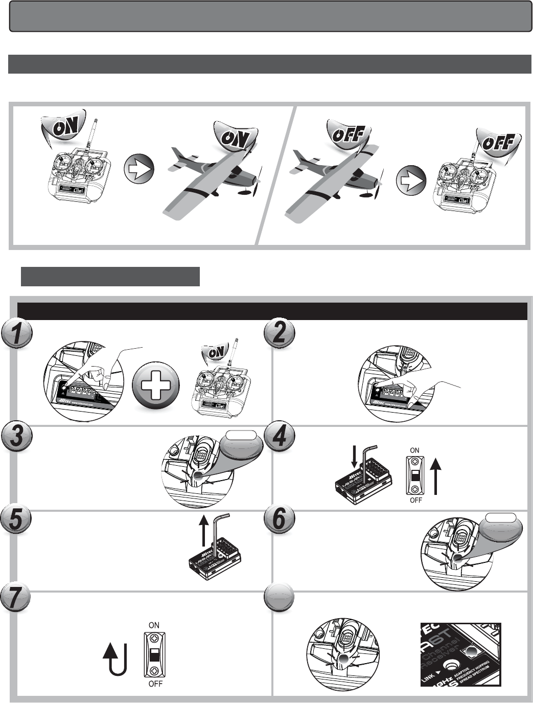
To turn the system on and off, use the following sequence at all times.
Turning Off -Turn off the receiver, then turn off the transmitter.Turning On -Turn on the transmitter, then turn on the receiver.
4. Set-up and Use of the LITE4 2.4
A. ID-Setup A.K.A, Link or Bind
Non-telemetry RXs (MINIMA & MICRO Series)
Press and hold the link button on Receiver and turn on the power.
Press and hold the button on the module, and turn on the transmitter.
BLUE LEDs will blink rapidly
to find the transmitter signal.
Release the link button when
BLUE LED on receiver glows steady.
When the link is completed, RED LED
on the module will blink.
Release the link button.
Check if RED LED is blinking.
press the link button for 2 sec.
2.4GHz 6 Channel
Aircraft Receiver
2.4GHz 6 Channel
Aircraft Receiver
Link
V-TAIL
OFF
ELEVON
CH1 CH2 CH3 CH4
REV
NOR
2.4GHz 4 Channel Aircraft Radio
Link
V-TAIL
OFF
ELEVON
CH1 CH2 CH3 CH4
REV
NOR
2.4GHz 4 Ch
NOR
Link
V-TAIL
OFF
ELEVON
CH1 CH2 CH3 CH4
REV
NOR
2.4GHz 4 Ch
NOR
10
To save the setting, please reboot both transmitter and receiver. When they are turned on again, RED LED on the module(or radio)
and BLUE LED on the receiver will glow steady.
6
Channel
R
eceiver
8
RED
LED
RED
LED
CH1CH2CH3CH4
REV
NOR
Link
V-TAIL
OFF
ELEVON
CH1 CH2CH3 CH4
REV
NOR
2.4GHz 4 Channel Aircraft Radio
Link
V-TAIL
OFF
ELEVON
CH1 CH2 CH3 CH4
REV
NOR
2.4GHz 4 Channel Aircraft Radio
CH1 CH2CH3CH4
REV
NOR
CH1 CH2 CH3 CH4
REV
CH1 CH2 CH3 CH4
REV
LITE4 2.4 Instruction Manual
B. SmartScan Function
C. Range Check Function
11
NOTE
After “Scanning,” you need to do the link process again for all your receivers as receivers need new
frequency hopping codes from the LITE4 2.4
It is critical that before each flight session you perform a range check that confirms the signal between the receiver and transmitter is
appropriate.
Unlike the FM/PPM or PCM signal radios, 2.4GHz systems use a fixed shorter, stubby transmitter antenna so the traditional method of range
checking your system by lowering the transmitter antenna will not work.
We instead use a power-down mode to reduce the transmitter signal strength. Once the power-down mode is activated when LINK button is
pressed, shortening the effective range 100 feet (30 m).
During this power-down mode, you should walk away from the secured aircraft, carrying the transmitter to a distance of approx. 30 meters
in order to test the effective range.
When release LINK button, power-down mode is finished and return to normal range mode.
Turn on the transmitter with pressing and holding the LINK button on the LITE4 2.4 for about 5sec.
When RED LED is blinking rapidly, release the Link button.
The LITE4 2.4 will automatically scan the frequency to find the cleanest and the most stable frequency in any area.
When the scan is completed, the RED LED on the module stops blinking. Re-boot the transmitter (turn Off and On)
and follow the link process with your receiver.
LITE4 2.4 Instruction Manual
Link
V-TAIL
OFF
ELEVON
CH1 CH2 CH3 CH4
REV
NOR
2.4GHz 4 Ch
NOR
CH1 CH2 CH3 CH4
REV
Link
V-TAIL
OFF
ELEVON
CH1 CH2 CH3 CH4
REV
NOR
2.4GHz 4 Channel Aircraft Radio
RED
LED
2Sec.
Push
&
D. Min. and Max. Range for Binding
12
E. Receiver-Servo Connection List
Receiver-Servo Connection List W/ LITE4 2.4
The table below shows where the aircraft's servos should plug into a receiver. Note that some functions shown will not operate until they are activated
in the transmitter. The standard function is listed first for each channel.
- Binding must be done within 15ft. (5m) of the transmitter and receiver.
- The Transmitter and receiver need to be at least 18in. (45cm) from each other to bind properly.
50Cm(18in)5M(15ft)
MAX RANGE
MIN RANGE
RX CH ACRO(Normal) ACRO(Elevon) ACRO(V-Tail)
Link
V-TAIL
OFF
ELEVON
CH1 CH2 CH3 CH4
REV
NOR
2.4GHz 4 Channel Aircraft Radio
CH1 CH2 CH3 CH4
REV
NOR
LITE4 2.4 Instruction Manual
V-TAIL
OFF
ELEVON
H
3 CH4
REV
NOR
2
.4GHz 4 Ch
F. Trim Adjustment
This is a function for setting the trim values for each of the servos, allowing you to make adjustments to each individual servo independently of the
trim switches located near the control stick of the radio (which can be adjusted in flight).
We recommend that you first set up the model's servo pushrods so that the control surfaces are as centered as possible mechanically before
attempting to adjust them in the trim switch. We also recommend that you try to keep all the trim values at the center position. If the values are
skewed to once side, the servo's full range of travel may be restricted.
ELVN (Elevon mix)
Setting Up Elevons
If you are setting up a tail-less delta or flying wing aircraft, you can use this program to activate the pre-programmed elevon mix that mixes the output
on the CH 1 aileron and CH 2 elevator servo channels.
As you will notice in the servo connection chart, you plug one aileron servo in the receiver's channel 1 slot and the other aileron servo into channel
2-the slot that usually feeds the elevator.
This is necessary because on these wing types, the ailerons must double as elevators.
G. ELVN (Elevon Mix)
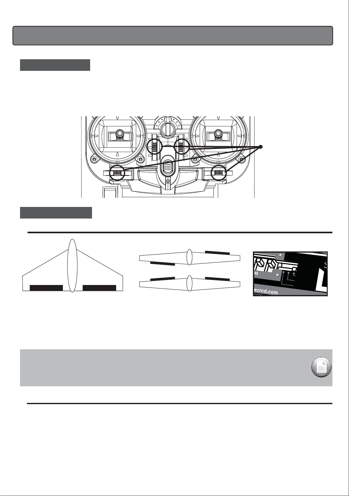
1) Activate the elevon function by pushing the pre-programmed switch to the left. Now check your model to see what happens when you move the
right-hand joystick side to-side. The ailerons should go up and down appropriately.
Move the joystick forward and back to see if the ailerons both respond correctly as elevators.
If necessary, use the REV function to reverse an offending servo.
2) Now set the amount (and direction if necessary as noted above) of each servo-both as ailerons and as elevators.
Because flying wings are extraordinarily pitch sensitive (because the elevator control surface is so close to the airframe's center of gravity),
you generally need the elevator travel and adjust horn linkage hole to be much less than that of the ailerons.
Front view
CH1 CH2
Aileron Operation
Elevator Operation
NOTE:
When you activate ELVN, note that the V-tail mixing is rendered unavailable by the radio.
When you change the function of ELVN to V.TAIL or V.TAIL to ELVN,
Please TURN OFF THE TRANSMITTER FIRST and then change the function.
If you change the ELVN and V-TAIL functions when the transmitter is ON, nothing will be changed.
13
Trim Switch
CH4
REV
NOR
LITE4 2.4 Instruction Manual
14
H. S. REV (Servo Reverse)
S. REV (Servo Reverse)
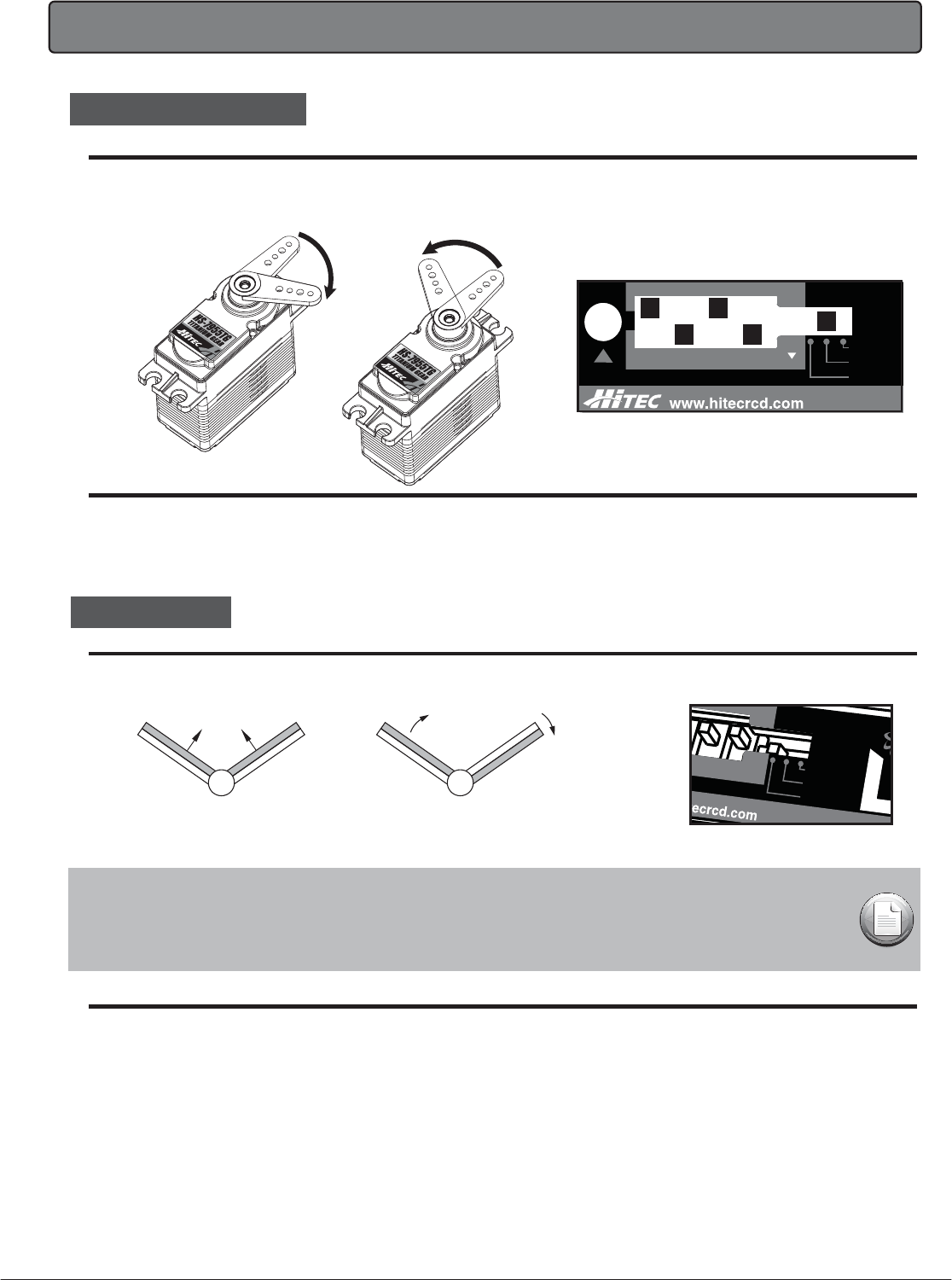
When you first turn on your model, you will immediately see whether all the control surfaces are moving in the correct direction when you wiggle the controls.
If any are moving in reverse, you can come to this screen to reverse the throw of the offending servo.
Normal Reversed
Reversing a Servo
Let's say your elevator is going down when you pull back on the joystick, that is definitely not going to be a good situation when you go to fly your plane!
To reverse the elevator servo, come to the switch in front of the radio’s front panel. You'll notice that the symbol NOR and REV,
move the switch either NOR or REV to make the servo operate in the proper direction.
V.TAIL (V-Tail)
I. V.TAIL (V-Tail)
This is another built-in mixing program available on the LITE4 2.4 that mixes the rudder and elevator servos for controlling V-tailed aircraft.
Similar to elevon programming, the two surfaces can move up and down together (for elevator control) or opposite (for rudder control in this case).
Setting Up a V-Tail
1) Activate the function by pushing the pre-programmed switch to the right.
2) With your model turned on, check your servo travel directions (both rudder and elevator channels) to be sure they are correct.
Use the REV switch if necessary to make the correction.
Surfaces can move up and down together (for elevator control) or opposite (for rudder control in this case).
CH2 CH4 CH2 CH4
Up Elevator Right Rudder (view from rear)
NOTE:
When you select V.TAIL, the ELVN program is rendered unavailable.
When you change the function of ELVN to V.TAIL or V.TAIL to ELVN,
Please TURN OFF THE TRANSMITTER FIRST and then change the function.
If you change the ELVN and V-TAIL functions when the transmitter is ON, nothing will be changed.
V-TAIL
OFF
ELEVON
H
3 CH4
REV
NOR
2
.4GHz 4 Ch
Link
V-TAIL
OFF
ELEVON
CH1 CH2 CH3 CH4
REV
NOR
2.4GH
z
LITE4 2.4 Instruction Manual

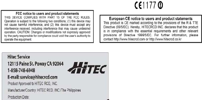
7. Service & Support
Hitec Service
12115 Paine St. Poway CA 92064
1-858-748-6948
E-mail: service@hitecrcd.com
Hitec Customer Service
Help is available from Hitec customer service through phone support and e-mail inquiries.
Our US oce is generally open Monday thru Friday, 8:00AM to 4:30PM PST. These hours and days may vary by season. Every attempt is made to answer
all incoming service calls. Should you get our voice mail, leave your name and number and a sta member will return your call.
Hitec Website
Make plans to visit the Hitec website, www.hitecrcd.com, on a regular basis. Not only is it full of specs and other information about the entire Hitec
product line, our FAQ pages will eventually hold valuable information and updates regarding about the Spectra 2.4 module and Optima series of receivers.
The On-Line Community
One of the benets of the extensive R/C online community is the vast wealth of archived knowledge available. Hitec sponsors forums on most of the
popular R/C websites where a Hitec sta member or representative tries to answer all manner of product related questions. Bringing together strangers
with common interests is proving to be one of the greatest gifts of
the internet. If past history is any guide to the future, we are certain forums will be
started about
the Hitec 2.4GHz system and several are certain to stand out as valuable archives of information.
Warranty and Non-Warranty Service
All Hitec products carry a two year from date-of-purchase warranty against manufacturer's defects.
Our trained and professional service representative will
determine if the item will be repaired or replaced. To provide all the necessary information we need to administrate your repair, visit our website at
www.hitecrcd.com and download the repair form, ll it out and send in your item for repair.
- Always turn your transmitter on first and off last.
- Never fly your airplane without first performing a proper range check.
- FCC regulation in the USA prohibits consumers from changing the crystal in the transmitter.
For channel changes send your system to an authorized service/repair center.
- Never fly around or over houses, people or power lines.
- Always charge your batteries before you fly.
- Always fly responsibly and respect the rights of others.
- Make sure your frequency is clear before turning on your system.
5. Precautions
The mode can be changed by distributor in your country if you wish to change the mode. (mode 1 and2)
It is not allowed to change the mode by yourself at your discretion.
6. Mode Change
15
LITE4 2.4 Instruction Manual
openings and cause erratic operation or loss of control.
If you must fly in wet weather during a contest, be sure to protect your transmitter with a plastic bag or
waterproof barrier.
FCC Information to User
This equipment has been tested and found to comply with the limits for a Class B digital device,
pursuant to Part 15 of the FCC Rules. These limits are designed to provide reasonable
protection against harmful interference in a residential installation. This equipment generates,
uses and can radiate radio frequency energy and, if not installed and used in accordance with
the instructions, may cause harmful interference to radio communications. However, there is no
guarantee that interference will not occur in a particular installation. If this equipment does
cause harmful interference to radio or television reception, which can be determined by turning
the equipment off and on, the user is encouraged to try to correct the interference by one of the
following measures:
• Reorient or relocate the receiving antenna.
• Increase the separation between the equipment and receiver.
• Connect the equipment into an outlet on a circuit different from that to which the receiver is
con-nected.
• Consult the dealer or an experienced radio/TV technician for help.
Caution
Modifications not expressly approved by the party responsible for compliance could void the
user’s authority to operate the equipment.
FCC Compliance Information : This device complies with Part 15 of the FCC Rules.
Operation is subject to the following two conditions: (1) This device may not cause harmful
interference, and (2) this device must accept any interference received, including interference
that may cause undesired operation
IMPORTANT NOTE:
FCC RF Radiation Exposure Statement:
This equipment complies with FCC RF radiation exposure limits set forth for an uncontrolled
environment. This equipment should be installed and operated with a minimum distance of 20
centimeters between the radiator and your body.This transmitter must not be co-located or
operating in conjunction with any other antenna or transmitter.
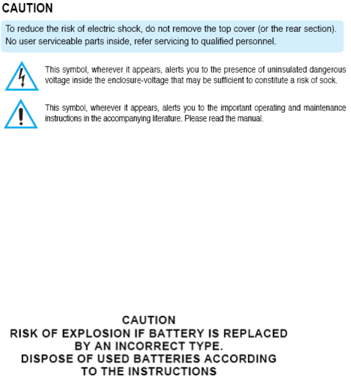
IMPORTANT Safety Instruction:
1) Read these instructions.
2) Keep these instructions.
3) Heed all warnings.
4) Follow all instructions.
5) Do not use this equipment near water.
6) Do not using near any heat sources such as radiators, heat resisters, stove, or other
equipment that produce heat.
CONTACT INFORMATION
Manufacturer Address : Lot 6 and 8, Blk. 24, Phase 4 CEPZ, Rosario, Cavite, Philippines
To locate in-country Hitec RCD KOREA, INC. distributors of the LITE4
please refer to the Hitec RCD KOREA, INC. Website http://www.hitecrcd.co.kr/
These distributor(s) represent local contacts for this product.
CORPORATE HEADQUARTERS:
Hitec RCD KOREA, INC.
653, YangCheong-Ri, Ochang-Eup, CheongWon-Gun, Chung Buk Province, Korea
Tel: 82-43-717-2071
Fax:
82-43-717-2193
Web: http://www.hitecrcd.co.kr/
This device complies with Industry Canada license-exempt RSS standard(s).
Operation is Subject to the following two condition: (1) this device may not cause interference,
and (2) this device must accept any interference, including interference that may cause undesired
operation of the device.

EUROPEAN UNION “DECLARATION OF CONFORMITY”
DECLARATION OF CONFORMITY
Hitec RCD KOREA, INC.
653, YangCheong-Ri, Ochang-Eup, CheongWon-Gun,
Chung Buk Province, Korea
declare under our sole responsibility that the product(s)
2.4GHz Radio Control System – LITE4
to which this declaration relate(s) is in conformance with the following standards:
EN 301 489-1 V1.8.1:2008
EN 301 489-17 V2.1.1 :2009
EN60950-1:2006
EN 300 328 V1.7.1:2006
following the provisions of the 1999/5/EC Directives.

Congratulations again and have fun!
2.4GHz 4 Channel Aircraft Radio