Hitec RCD LYNX4S 2.4GHz Radio Control System User Manual
Hitec RCD Inc. 2.4GHz Radio Control System Users Manual
User Manual

Intro.
Thank you for purchasing the LYNX 4S transmitter. LYNX 4S is composed of diverse features to maximize customer’s R/C experiences. Please read
carefully to become familiar with LYNX 4S under your control. After reading this, please keep this manual for easy reference.
Product Specifications
- Frequency Range : 2.4092GHz~2.474GHz
- Modulation : Frequency Hopping Spread Spectrum (FHSS)
- Tx Power : Max. 100mW
- Channel : 109Ch(random 21 ch among 109 ch)
- Operating Temperature : -10℃ ~ +50℃
- Power : 4.8VDC
Features
- 4096 Resolution
- Intenna Surface FHSS 2.4GHz
- HHR (HITEC HIGH Resolution) SYSTEM 4ms (ONLY AXION 2)
- Backlight Graphic LCD Screen
- Six Colors LED(RED/GREEN/BLUE/YELLOW/MAGENTA/CYAN)
- CAR / Boat / 4WD / Crawler Channel Mixing
- Spring Tension Control(Steering / Throttle)
- Three step Mixing Switch
- Steering / Throttle Gimbal ballbearing
- Vibration motor Warning Mode
- Music play Mode(ONLY wav file)
- Warning voice file(ONLY wav file)
- Two-way Telemetry(RPM , SPEED , TEMP , VOLT)
- Micro SD

- 30 – Model Memory(Micro SD - Add 30 memory, Total 60 memory)
- 12 letter model name
- Easy Left-hander change Mode
- PC link and Upgrade
- Earphone connection
- Extension Mountain Mode
- Various Battery Compatibility(Lipo / Life / NiMH / NiCD)
Transceiver Binding(ID setting)
<TX>
1. Power ON_(Get off down SW_ Displayed in the upper right corner of the screen, you must have a RF.)
2. Dial SW press once(Go to the menu screen.)
3. Dial SW keep turning down the SYSTEM menu.
4. RX-BIND Position the cursor in the menu, press the Dial SW.(Go to the RX-BIND screen.)
5. RX-MODEL Dial SW Position the cursor on by pressing Receiver, so you can choose the right move the cursor.
6. AXION 2 Position the cursor, press ESC on. (Go to the RX-MODEL.)
7. Dial SW Turn down the the START position
8. START is pressed, the LED color will change BINDING runs.
<Dial SW>
<RX>
1. RX-click the Link button on the power (4.8V) is applied to the link SW release.
2. RX intersection Blinks the LED on the end of the BLUE color.
3. The power OFF and then ON.
<TX>
9. RX and press ESC SW BINDING is complete.
10. For about 5 seconds, then press ESC SW twice more, go to the main menu screen.
(Warning – Available LINK range of Tx and Rx is between 45cm and 5M. If LINK cut off more than 1 second because of the external
environment in the Scan Mode or one of transceiver’s power is turned off, you have to turn off both the Tx and Rx then LINK again.)
Servo Monitor Mode(TX and RX are available in the state BINDING)
1. From the main screen, press the Dial SW, entry menu screen.
2. Dial SW keep turning down the SYSTEM menu.
3. SERVO menu, position the cursor, press the Dial SW. (Go to the MONITOR screen.)
4. Dial SW Lift up again, go to the TEST menu, press the Dial SW.
(Go to the Speed adjustment menu.)
5. Dial SW by turning the variable speed servo (up to make it faster.)
6. ESC twice while pressing the stop menu.
Transmitter Scan Mode
1. LYNX 4S Power ON, Move to SYSTEM TAB.
2. RX-SCAN Menu button entered will appear asking if you want to scan.
"You will run a scan is it? Then all you need to rebind RX! "
3. YES by pressing SCAN is executed.
4. Process again after complete to BINDING of the transceiver.
Fail safe and hold mode
When Rx signal take effect on external influence if you set the Fail - safe mode, the servo will go to Fail–safe position you stored already. The servo
will turn off the power for 1 second in hold time if you didn’t enable the Fail–safe mode. Then the servo will keep no-load condition and move to the
position that is ordered last time until it detects a normal signal again. Always, the Fail-safe mode must be enable for safe flight and the Fail-safe
mode is required safe flight status like the engine idling, the motor stop, extended air brake, etc.
- Fail-safe set-up
1. After the transmitter power ON SET 1/2 TAB to select the FAILSAFE.
2. If you select SET on each channel can be set as the FAILSAFE mode.
3. ST & TH moves and the number at the bottom of the current value is displayed.
4. After setting the desired value, press SET to save the value.
5. May set the value stored for each channel by pressing the SEND Data is sent to the receiver.
6. Once the receiver is receiving Data ON after the power is turned OFF.
7. Check the servo move to the Fail-safe position.
- Fail-safe Setting TEST
1. The flight move to the any place that is not the Fail-safe setting.
2. It is the normal Fail-safe setting if the servo moves to the Fail-safe position you set lastly after you turn off the Tx.
- The way to re-enable the Hold mode in Fail-safe mode.
1. After the transmitter power ON SET 1/2 TAB to select the FAILSAFE.
2. Each channel is HOLD selected, HOLD mode can be set.
3. ST & TH moves and the number at the bottom of the current value is displayed.
4. After setting the desired value, press SET to save the value.
5. May set the value stored for each channel by pressing the SEND Data is sent to the receiver.
6. Once the receiver is receiving Data ON after the power is turned OFF.
7. Check the servo move to the Fail-safe position.

(Warning – The Fail-safe setting will delete you set lastly if the Fail-safe mode is disabled. Always check the Fail-safe mode work normally
before you turn on the engine or motor.)
Low Battery Warning
- The battery voltage is normal, there is no change in the module.
- The battery voltage is low, the alarm sounds. Please check the battery voltage immediately if you here a beep in flight.
Range Check
Please check the range for verifying that transceiver operate normally.
(Warning – Transceiver Pre-set the ID for user’s convenience when it comes from factory.)
Warnings and Precautions
- Don’t steer this in the busy street.
- Don’t steer this in the rain and on the standing water.
- Don’t steer this after drink alcohol.
- Always check the remaining battery power.
- Always power on the Tx first then power on the Rx next to prevent failure.

WARNING & SAFETY INFORMATION 7
WARNING & SAFETY INFORMATION
Safety Symbols
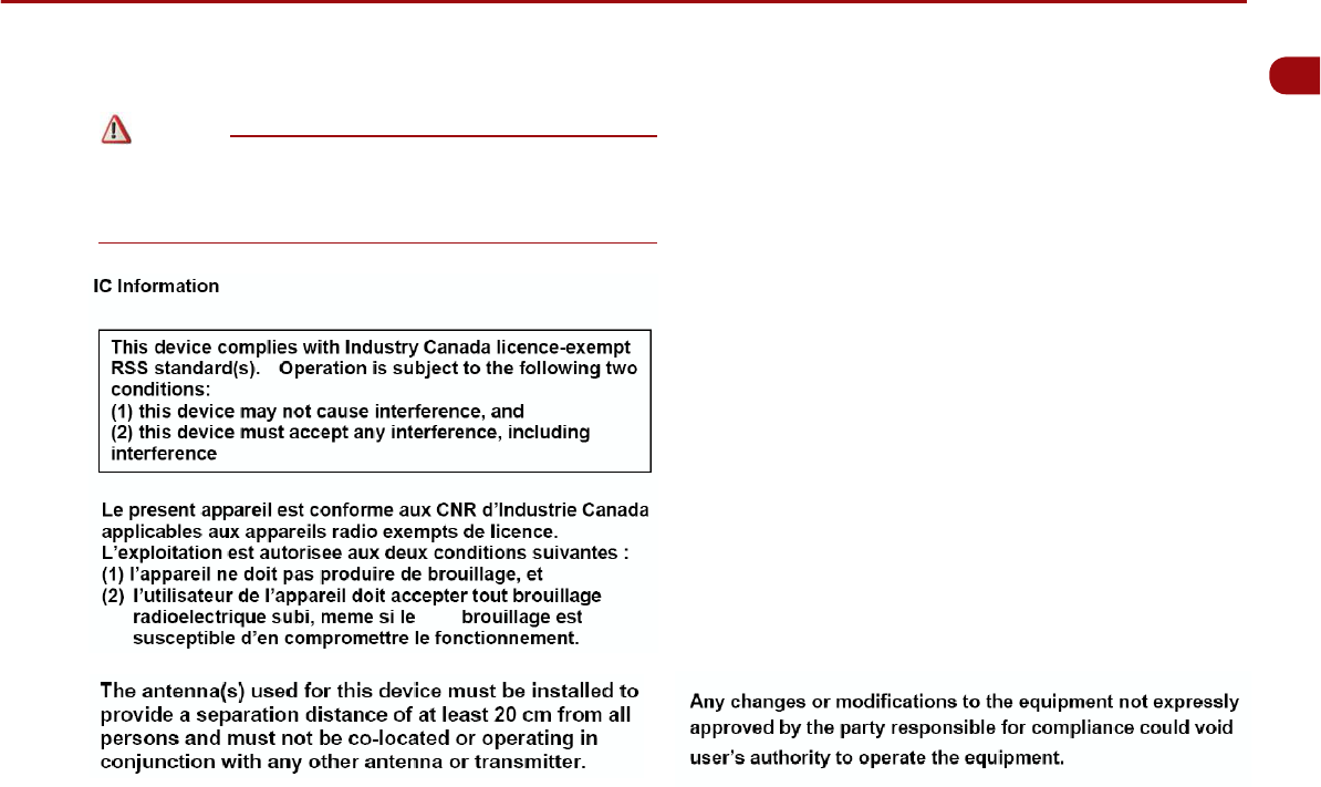
FCC Information
6JKUFGXKEGEQORNKGUYKVJRCTVQHVJG(%%4WNGU1RGTCVKQPKUUWDLGEV
VQVJGHQNNQYKPIVYQEQPFKVKQPU
6JKUFGXKEGOC[PQVECWUGJCTOHWNKPVGTHGTGPEGCPF
6JKUFGXKEGOWUVCEEGRVCP[KPVGTHGTGPEGTGEGKXGFKPENWFKPI
KPVGTHGTGPEGVJCVOC[ECWUGWPFGUKTGFQRGTCVKQP
FCC notification to users
6JKUGSWKROGPVJCUDGGPVGUVGFCPFHQWPFVQEQORN[YKVJVJGNKOKVUHQTC
%.#55 $ FKIKVCN FGXKEG RWTUWCPV VQ 2CTV QH VJG (%% 4WNGU 6JGUG
NKOKVUCTGFGUKIPGFVQ RTQXKFGTGCUQPCDNGRTQVGEVKQPCICKPUVJCTOHWN
KPVGTHGTGPEGYJGPVJGGSWKROGPVKUQRGTCVGFKPCEQOOGTEKCN
GPXKTQPOGPV 6JKU GSWKROGPV IGPGTCVGU WUGU CPF ECP TCFKCVG TCFKQ
HTGSWGPE[GPGTI[ CPFKH PQVKPUVCNNGF CPFWUGF KPCEEQTFCPEG YKVJVJG
KPUVTWEVKQPU OC[ ECWUG JCTOHWN KPVGTHGTGPEG VQ TCFKQ EQOOWPKECVKQPU
*QYGXGTVJGTGKUPQIWCTCPVGGVJCVKPVGTHGTGPEGYKNNPQVQEEWT KP C
RCTVKEWNCTKPUVCNNCVKQP+HVJKUGSWKROGPVFQGUECWUGJCTOHWNKPVGTHGTGPEG
VJG WUGT KU GPEQWTCIGF VQ VT[ VQ EQTTGEV VJG KPVGTHGTGPEG D[ EQPUWNVKPI
YKVJC-+#FGCNGTQTCPGZRGTKGPEGFVGEJPKEKCPHQTVGEJPKECNCUUKUVCPEG
㿋#
9JGPGPEQWPVGTKPIVJKUU[ODQNKPVJGOCPWCN[QWOWUVHQNNQYVJGUG
TGEQOOGPFCVKQPUVQCXQKFKTTGRCTCDNGFCOCIGVQ[QWTECTU[UVGOQT
EQPPGEVGFFGXKEGUQTVQCXQKFCEEKFGPVUYKVJKPLWTKGUQTFGCVJ
㿋#
9JGPGPEQWPVGTKPIVJKUU[ODQNKPVJGOCPWCN[QWOWUVDGXGT[
ECTGHWNCPFHQNNQYVJGTGEQOOGPFCVKQPUVQCXQKFFCOCIGVQ[QWTECT
U[UVGOQTEQPPGEVGFFGXKEGUQTVQCXQKFKPLWT[
㿋#
+PHQTOCVKQPYJKEJ[QWOWUVDGCYCTGQHQTTGEQOOGPFCVKQPUHQT[QWT
EQPXGPKGPEGCPFHQTQRVKOCNQRGTCVKQPQH[QWTU[UVGO
Note
Caution
Warning