Hitec RCD LYNXSP2A75 75 MHz Remote Control Transmitter User Manual users instructions
Hitec RCD Inc. 75 MHz Remote Control Transmitter users instructions
users instructions

1
CONTENTS
INTRODUCTION
LAY-OUT DIAGRAM
FEATURES AND SPECS
SETTING AND OPERATION
1. TRANSMITTER
a. Loading batteries:
b. Reading the LED Battery Indicators
c. Recharging NiCad Batteries
d. Transmitter Antenna
e. Changing X-Tals
2. Installation of Receiver and Servos
a. Using separate power source for the receiver
b. Battery Eliminator Circuitry (B.E.C.) with Mechanical Speed Control
c. Connection with Electronic Speed Control
3. Transmitter, Receiver and servo settings
a. Checking operation of the servo
- Steering Servo Settings
- Steering servo trim setting
b. Throttle Servo Settings
- Using Mechanical Speed Control
- Using electronic speed control
- Using throttle servo for Gas powered vehicles

2
INTRODUCTION
Thank you for purchasing the LYNX Sport 2 Channel FM Radio System. The LYNX Sport
Radio is made of high quality, technically advanced components designed to achieve top
performance from your RC vehicle. Team up with Hitec Racing and see that quality and
performance doesn’t have to cost a fortune!
LAY-OUT DIAGRAM
(Illustration)

3
FEATURES AND SPECS
* Pistol Grip 2 Channel AM Proportional System
* Servo Reversing Switches (Both Channels)
* 2 L.E.D. Battery Status Indicator
* NiCad Battery Charging Jack
* Power Output : 500mW
* Current Drain : 180 mA
SETTING AND OPERATION
1. TRANSMITTER
a. Loading batteries:
You may use either Alkaline or NiCad “AA” size batteries.
* Push the bottom battery cover in the direction of the arrow then lift up the cover
* Load 8 AA batteries (Be sure the polarity is correct)
* Reinstall battery cover
* NiCads should be charged with CG-25 charger for aproximately 12 hours before use
b. Reading the LED Battery Indicators
* Normal: Green
* Warning: Flashing Red
With new alkaline or freshly charged nicads the Green light should be brightly lit; as the
green light starts to fade the Red begin illuminate and eventually light completely as the
green light goes out. Once this occures, operation should be stopped immediately, and the
batteries should be recharged or replaced. (Warning: Recharge nicads batteries only.
Alkaline batteries can not be recharged)
c. Recharging NiCad Batteries
The LYNX Sport is equipped with an external charging jack so there is no need to remove the
batteries from the transmitter to charge them. The Hitec CG-22 or 25A can be used to charge
the batteries overnight, or for approximately 12-15 hours. Please refer to the following
diagram, check to see that the charge lights lit after the connection is complete.
d. Transmitter Antenna
Always make sure your antenna is attached before use or you operating range will be greatly
reduced and could result in damage to your vehicle and or injuries to yourself and others.
e. Changing X-Tals
Changing X-Tal to avoid conflicts with other vehicles is possible where permitted.(You must
check your local rules before doing so. For example in the US the FCC prohibits the changing
of transmitter X-Tals on 72 and 75mhz) . If you are eligible to change X-tals both the
transmitter and receiver X-tals must be changed together. You must change within the same
band, i.e. 75 MHz to 75 MHz , 27 MHz to 27 MHz, different bands can not be intermixed if
your radio is on 75 MHz then 27 MHz X-tals cannot be used. Use only Hitec X-tal when
changing frequencies.

4
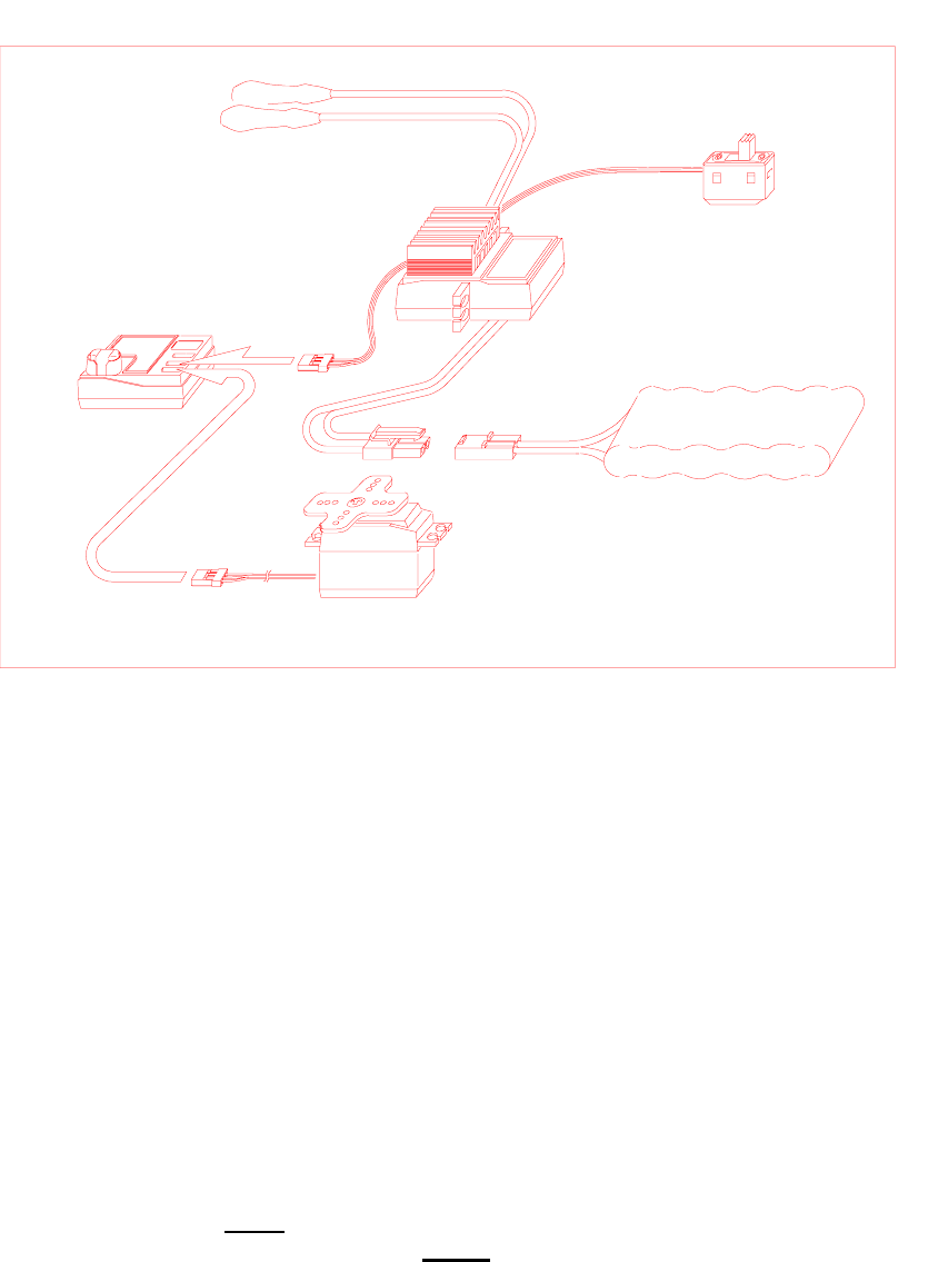
2. Installation of Receiver and Servos
a. Using separate power source for the receiver
When using a separate power pack for the receiver instead of sharing the main power source
for running , please refer to the following diagram. After installation, turn on the power to the
transmitter first then turn the receiver on (Warning: Always turn the transmitter ON first and
OFF last to prevent your vehical from running away.) This will prevent the receiver from
picking up stray signals and going out of control. Now, move the controls to see if the servos
are moving properly. If not, check your wiring or X-tals if the servos do not move at all.
(Illustration)
3. Battery Eliminator Circuitry (B.E.C.)
The Battery Eliminator Circuit allows the user to power the receiver from the main power
source for the motor. Most cars that use B.E.C. will have a plug coming off the mechanical
speed control. This plug is connected to the switch harness and then plugged directly in to the
receiver Batt/BEC slot. (Warning control may be lossed as the battery dies and the voltage
drops below the operating voltage of the reciever but still has enough power to sun the
motor) To be safe do not run the motor battery completely dead, stop it as it starts to slow.
4. Connection with Electronic Speed Control
Electronic Speed Control such as the Hitec HFX has a built in B.E.C. system inside the speed
control circuit. Plug the receiver connector from the speed control into the “THROTTLE” or
#2 channel on the receiver, and the steering servo into the “STEERING” or #1 channel on the
receiver. Now you can connect the main power to the speed control and when the power
switch is turned on the speed control will regulate the power that the receivers can use.
5
5. Transmitter, Receiver and servo settings
Now we come to the critical part as proper installation of these three main components is
essential.
a. Checking operation of the servo
* After installation of the servo and receiver into your model is complete, turn the power
“ON” the transmitter (fully extend the antenna) now turn on the receiver. (It is advisable
to remove the pinion gear from your car so that the wheels do not engage for this test)
* Check to see if both servos and/or speed control are working properly. If not check the
connections and/or make sure the main battery pack is charged.
* Check to see if the servos are moving in the correct direction. If not, change the servo
reversing switch located on the top of the transmitter to achieve the correct direction.
* If everything checks out then turn the receiver “OFF” first, then the transmitter
(Always remember Never have the receiver “ON” with out the transmitter being “ON” this
means when turning you model “ON” always turn the transmitter “ON” first and “OFF”
last)
Warning!!! : Do not shorten the length of the receiver antenna by cutting off any excess
wire this will severely affect the operating range and could result in injury to yourself and
others.

6
7
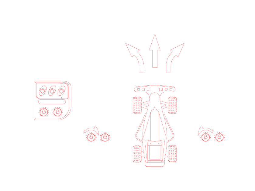
b. Steering servo trim setting
After verifying that the steering direction is correct, then set the steering trim knob to
the center if the servo horn or arm should be at 90 degrees and the wheels should be
straight. If not then make the horn or arm 90 degrees by removing it and replacing it
correctly. If the arm is at 90 degrees and the wheels are not straight adjust the linkage
to compensate. Once you’ve got these two setting correct the use the steering trim for
fine tuning. Note: (Always Trim your car before you run or race) This is a common
mistake made by beginners, if you have to steer your car to go straight, you are
fighting a loosing battle. Make sure it goes straight before you run and driving will
become much easier.
c. Throttle Servo Settings
- Using Mechanical Speed Control

8
Adjust the servo link rod so that point ”B” will come to the neutral position. Also
when the trigger is pulled to the maximum point “C” should be as illustrated and at
point “A” when the trigger is pushed to the limit. Check to see if the vehicle moves
forward when the trigger is pulled. If the vehicle moves backwards then the “Throttle”
reversing switch will need to be switched. If the model moves forward or reverse at
the neutral position then use the throttle servo trim to fine tune. If the servo moves the
speed control farther than is needed you will need limit the travel by moving the
linkage into a different mounting hole on the horn, closer to center will give less
travel and further from center will give more travel.
- Using electronic speed control
* Set the throttle trim in the center the adjust the ESC neutral point then the trim can
be used for fine tune adjustments.
Hint : Set a little drag brake in cars that are Understeering into the corners, and
no drag brake or a little “creep” for cars that Oversteer into the corners. This
means the car will “creep “ forward when the throttle is neutral, so you must push
the trigger forward to keep the car from moving when stopped. This can only be
done with forward only electronic speed controls, and is used in 4 wheel drive sedan
cars quite frequently to allow them to carry more speed into and through the
corner.
9
(Illustration)
* Adjust the full power position of the ESC (forward only) when the trigger is
pulled approximately 90% of the way. If the vehicle does not move forward when
the trigger is pulled and does when the trigger is pushed, check the motor
connection first, if that is correct then switch the “throttle” reversing switch to
correct.
* Adjusting the full power position of the ESC (Reversible version) is the same as
the forward only version, except you must make sure you are adjusting the forward
not the reverse. If the trigger is pulled and the full power adjustment does not effect
the speed but does when the trigger is pushed, the servo reversing switch for the
“throttle” needs to be switched. After this is determined, use the same 90% as
discussed previously for forward. Reverse on most speed controls is not adjustable.
(Illustration)
- Using throttle servo for Gas powered vehicles
Gas powered vehicles require the throttle servo to be set up to operate the carburetor and the
brakes together. The position of the control horn in the horn will determan the amount of
travel, this must be set up properly to get the proper throw for the throttle and brakes. Setups
are different for individual applications so consult the manufactures manual for the proper set
up procedure.