Hitec RCD OPTIC6SP-24G 2.4GHz 6CHANNEL RADIO CONTROL SYSTEM User Manual optic 6 sp
Hitec RCD Inc. 2.4GHz 6CHANNEL RADIO CONTROL SYSTEM optic 6 sp
UserManual.wiki
>
Hitec RCD
>
OPTIC6SP 24G User Manual
Users Manual
Navigation menu
Upload a User Manual
Namespaces
Wiki Guide
HTML
PDF
Info
Views
User Manual
Discussion / Help
Navigation
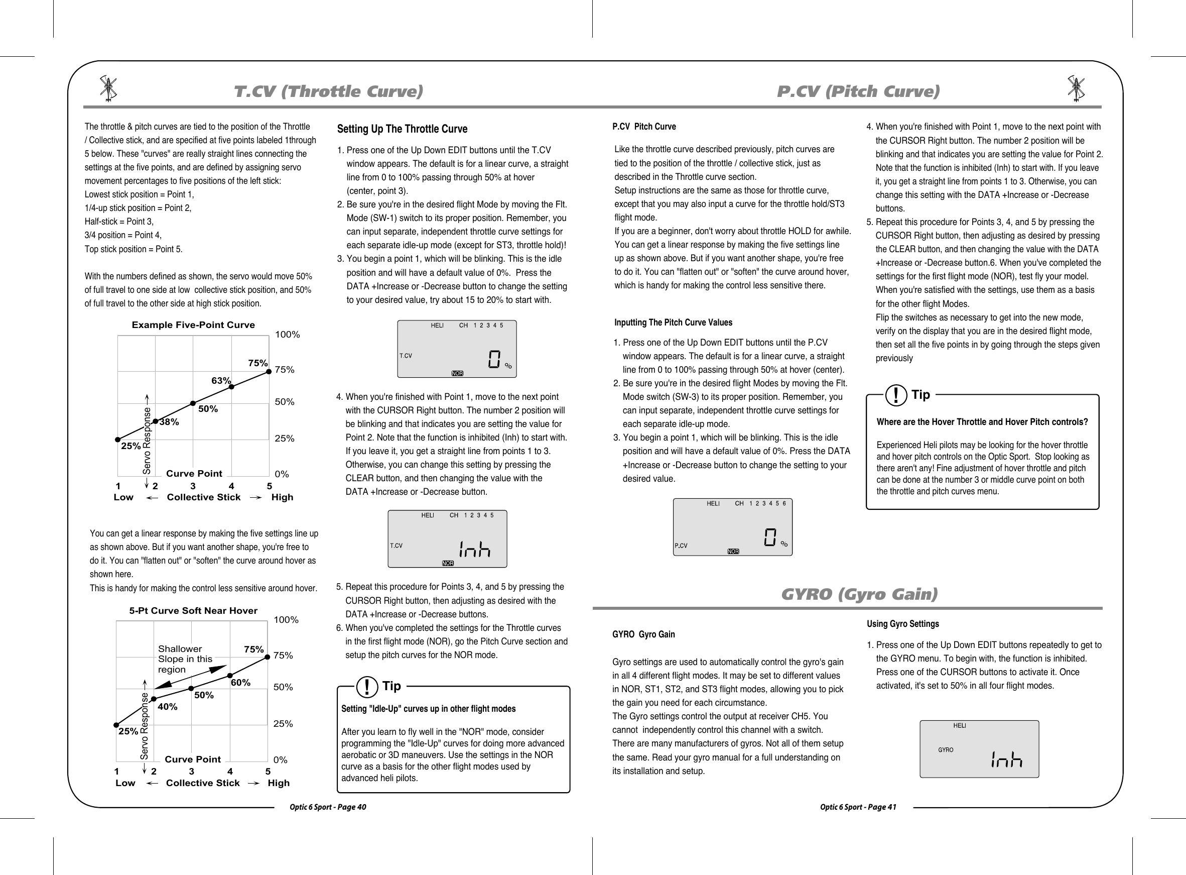
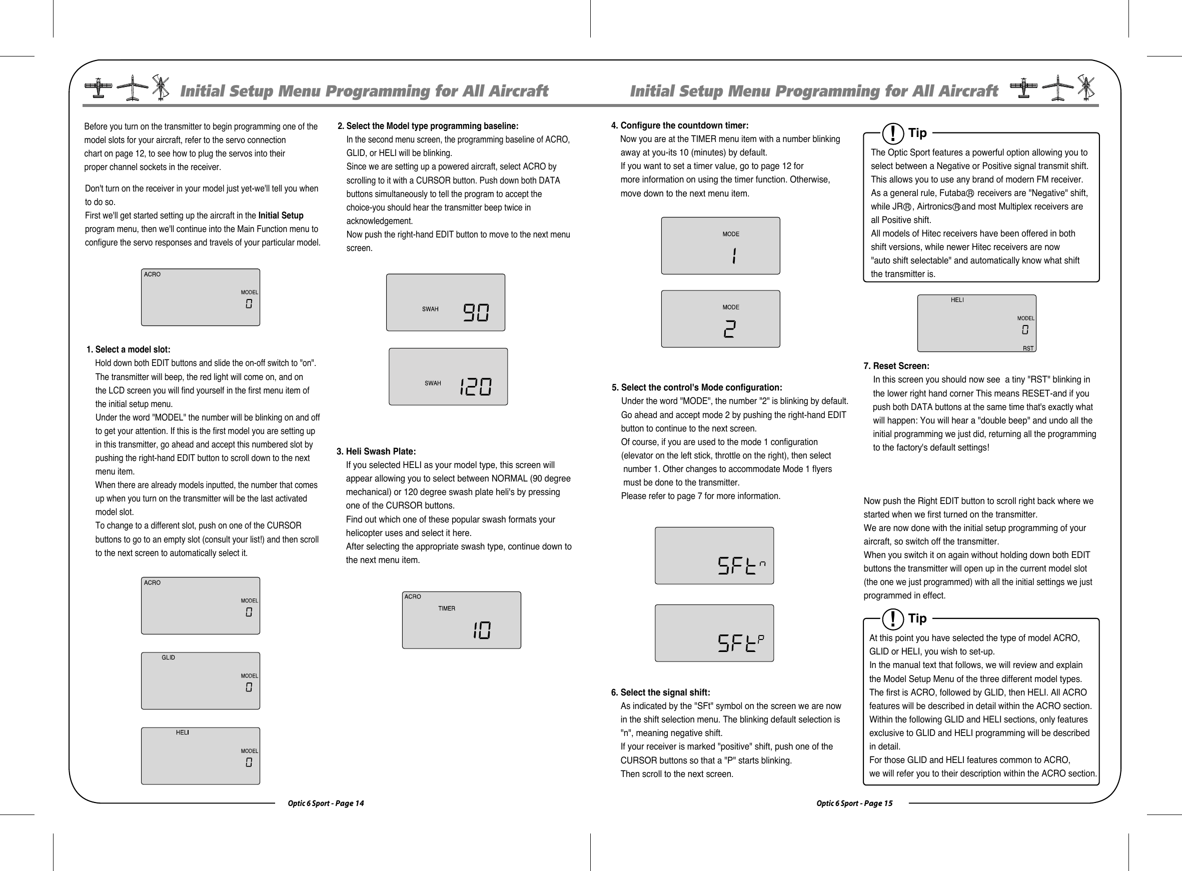
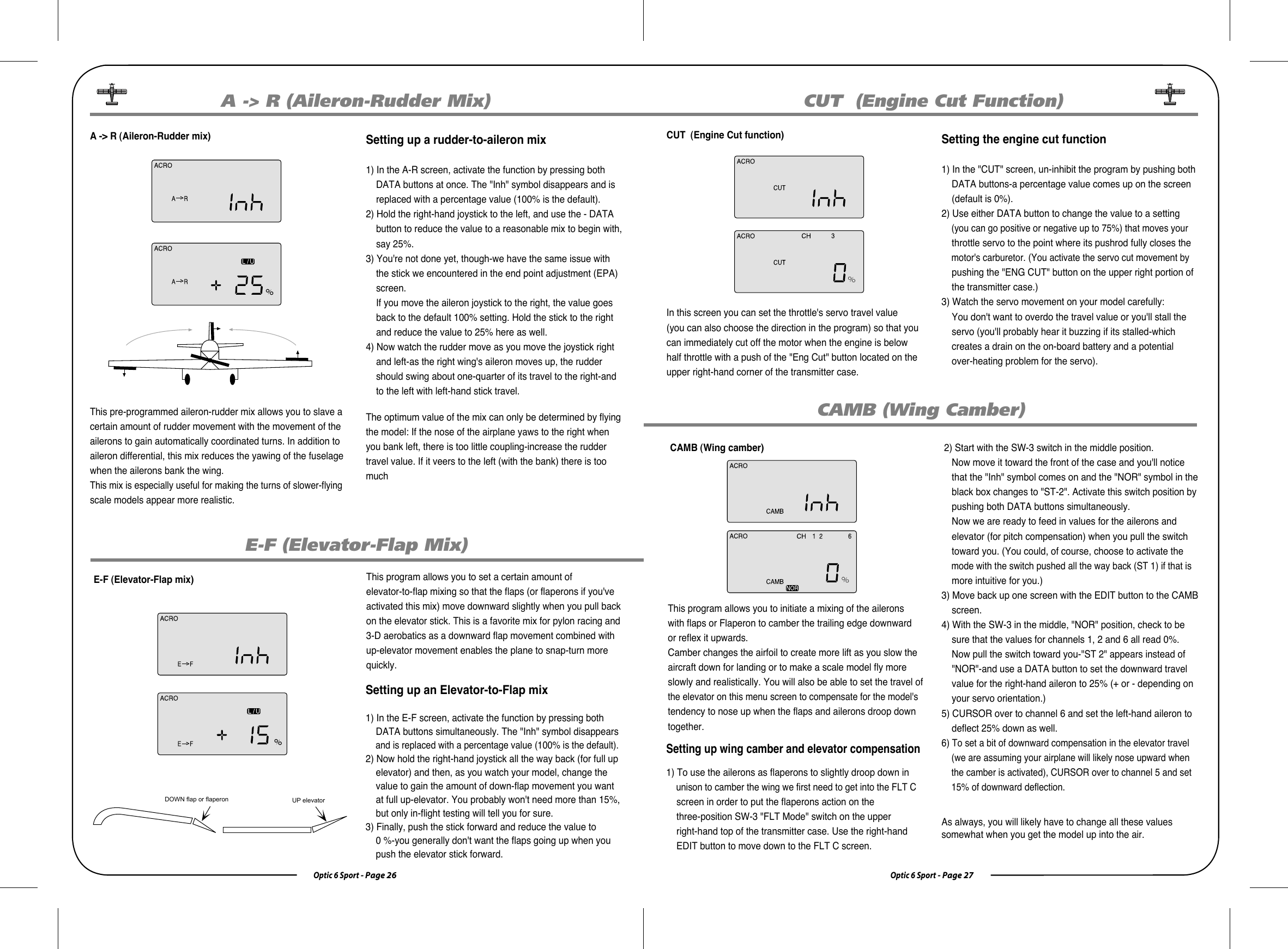
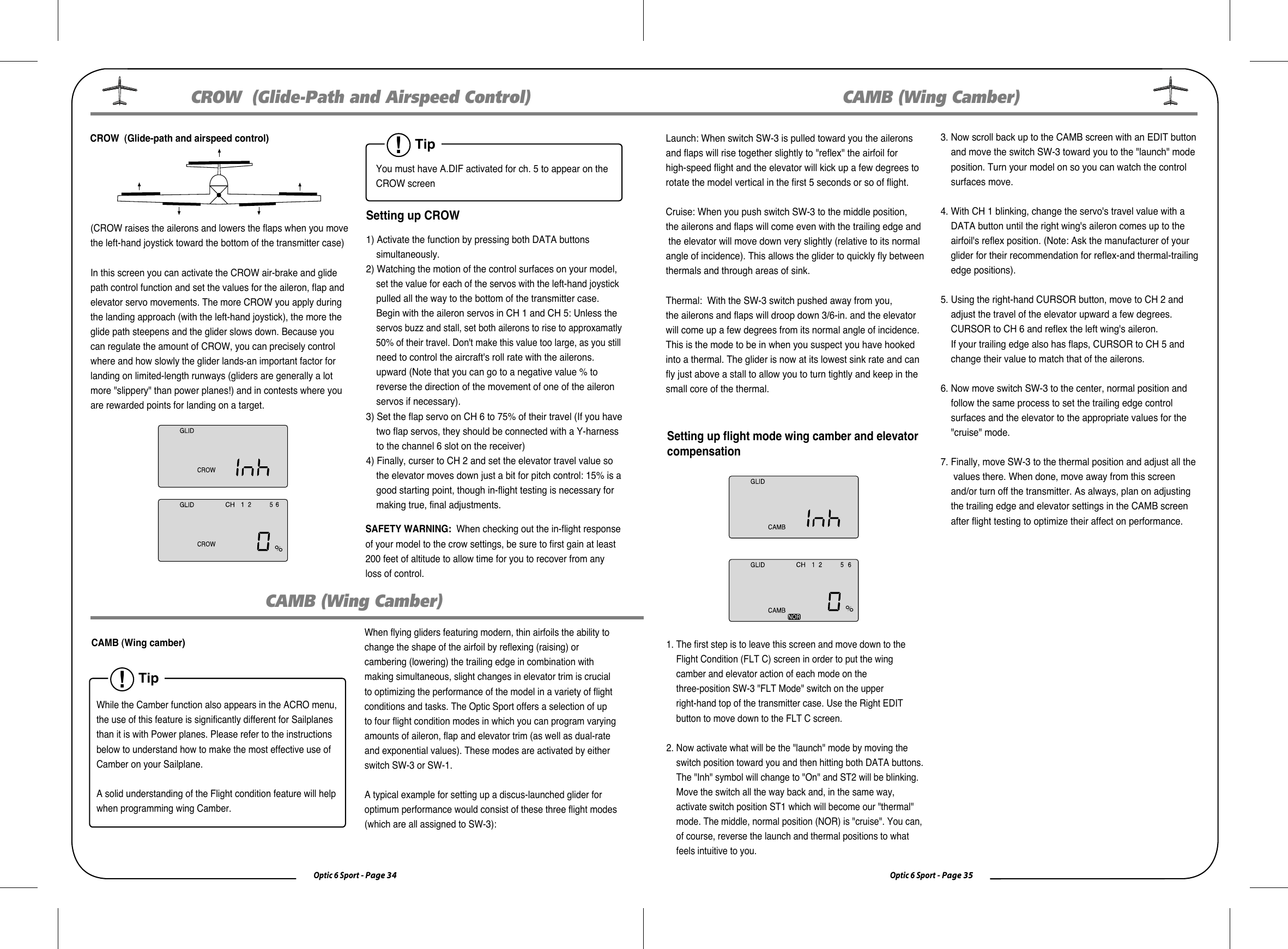
![Optic 6 Sport - Page 12Optic 6 Sport - Page 13TimerIf you push either DATA button, you will enable the radio's timer mode. The word "TIMER" appears on the screen as well as a number indicating the starting countdown time (which you can set in the Initial Setup menu). If you push the right hand CURSOR button, the timer will start counting down and the numbers will diminish in one-second increments. Push it again and the countdown stops. Pushing the left hand CURSOR button resets the timer.Lock Indicator ScreenWhen you push the Lock button to hold the throttle at an idle, the word "LOCK" appears in a black box above the voltage value. When you push the lock button again, this symbol disappears toindicate that you have disabled the function. Receiver-Servo Connection ListTransmitter Displays and MessagesThe table below shows where the aircraft's servos should plug into a six-channel receiver. Note that some functions shown will not operate until they are activated in the transmitter. The standard function is listed first for each channel.When you first turn on your transmitter, the first screen shown below appears on the LCD display. Before flying, or even starting the engine, BE SURE that the model number appearing next to the voltage matches the model that you are about to fly! If you don't, reversedservos and incorrect trims will lead to an immediate crash. If you press timer or engine cut or lock keys, you go directly tothose functions regardless of the display.This screen appears whenever you turn on the transmitter without pushing any other buttons. The model number currently enabled is the small number just to the right of the battery voltage and the programming baseline for this model (ACRO, GLID or HELI) is shown in the upper left hand corner. In the center bottom of the screen "NOR" appears in a small black box indicating that the transmitter is in the "Normal" flight mode condition. Startup Screen Rx. Ch. ACRO GLID HELI Aileron Aileron Roll Cyclic One or Right Flaperon (FLPN ON) or Right Aileron (ADIF on) or Swash servo 1 (120¡Æ) or Right Elevon Elevator Elevator Pitch Cyclic Two or Right V tail (VTAL on) or Right V tail (VTAL on) or Swash servo 2 (120¡Æ) or Left Elevon (ELVN on) Three Throttle Throttle Throttle Four Rudder Rudder Tail Rotor or Left V tail (VTAL on) or Left V tail (VTAL on) Five Landing Gear Left Aileron (ADIF on) Gyro Gain Six Flap Flap Collective or Left Aileron (FLPN on) or Swash Servo 3 (120¡Æ)Warning Display (Low voltage)When the battery's voltage drops to 6.6 volts, this number starts blinking on the screen and the transmitter begins to steadily beep. If your plane is up in the air when this happens, land immediately so you can recharge the battery.Warning Display (Flight Condition other than NOR)If you turn the transmitter on and it immediately starts to beep while displaying the word "ON" on the screen, one of the flight condition modes other than Normal is switched on. The symbol in the black box at the bottom of the screen indicates which switch (SW1 or SW3) needs to be reset to Normal.Transmitter Displays and MessagesInitial Setup Menu Programming for All AircraftModel Select 0~9 [MODEL]Map of Basic Menu Functions MODEL Model select: choose on of ten model memories 14 ACRO Acrobatic model mode 14 GLID Glider model mode 14 HELI Helicopter model mode 14 SWAH 90 Nomal Swash Plate (HELI only) 14 SWAH 120 120* Swash Plate (HELI only) 14 TMER Timer setup 15 MODE 1 Transmitter mode 1 15 MODE 2 Transmitter mode 2 15 SFT N Negative Transmit Shift 15 SFT P Positive Transmit Shift 15 RST Reset memory 15Model Type[ACRO] or [GLID] or [HELI]Swash Plate type (HELI only)[90] [120]Timer setup [TIMER XX]Mode 1 and Mode 2Shift Dir. [SFT N] [SFT P]Reset Memory [RST]!Tip If this is your first AirplaneIf this is your first model Airplane, here are a few tips that willstreamline your experience in programming it. This will make more sense after you read through the manual. Refer back to this section when you are ready to begin the setup:1. Start with the correct model type, ACRO, in the Initial Setup Menu.2. Access the main programming menu, then use the REV function, and make sure all the servos are moving in the proper direction.3. After centering the servo arms manually as close as you can, use the S.TRM or sub-trim function to center the servos.4. Set your servo end points with the EPA function.5. Program -35% EXPO values for aileron, Ch. 1 and elevator, Ch. 2. 6. After your Plane is all ready to fly, put it on a shelf and go get an R/C flight simulator program for your PC. Spend quality time crashing the virtual plane in the simulator. Using a sim will save you hundreds of dollars spent on spare parts and countless hours of rebuilding time in the long run.7. Ready to fly your new Plane? If you are lucky you will know someone that is an experienced model pilot and would be willing to check over your plane and take it up for its first flight. This is HIGHLY RECOMMENDED, even if you have to drive a hundred miles to get to this person! If you are on your own, start slow and conservatively.](https://usermanual.wiki/Hitec-RCD/OPTIC6SP-24G/User-Guide-1204179-Page-7.png)
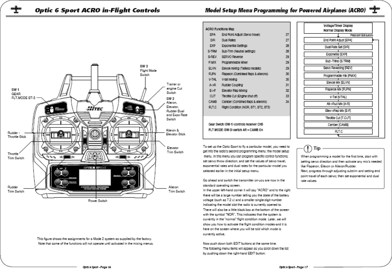
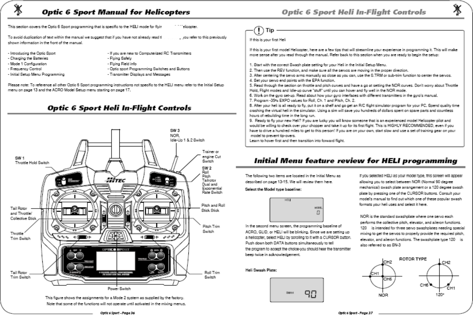
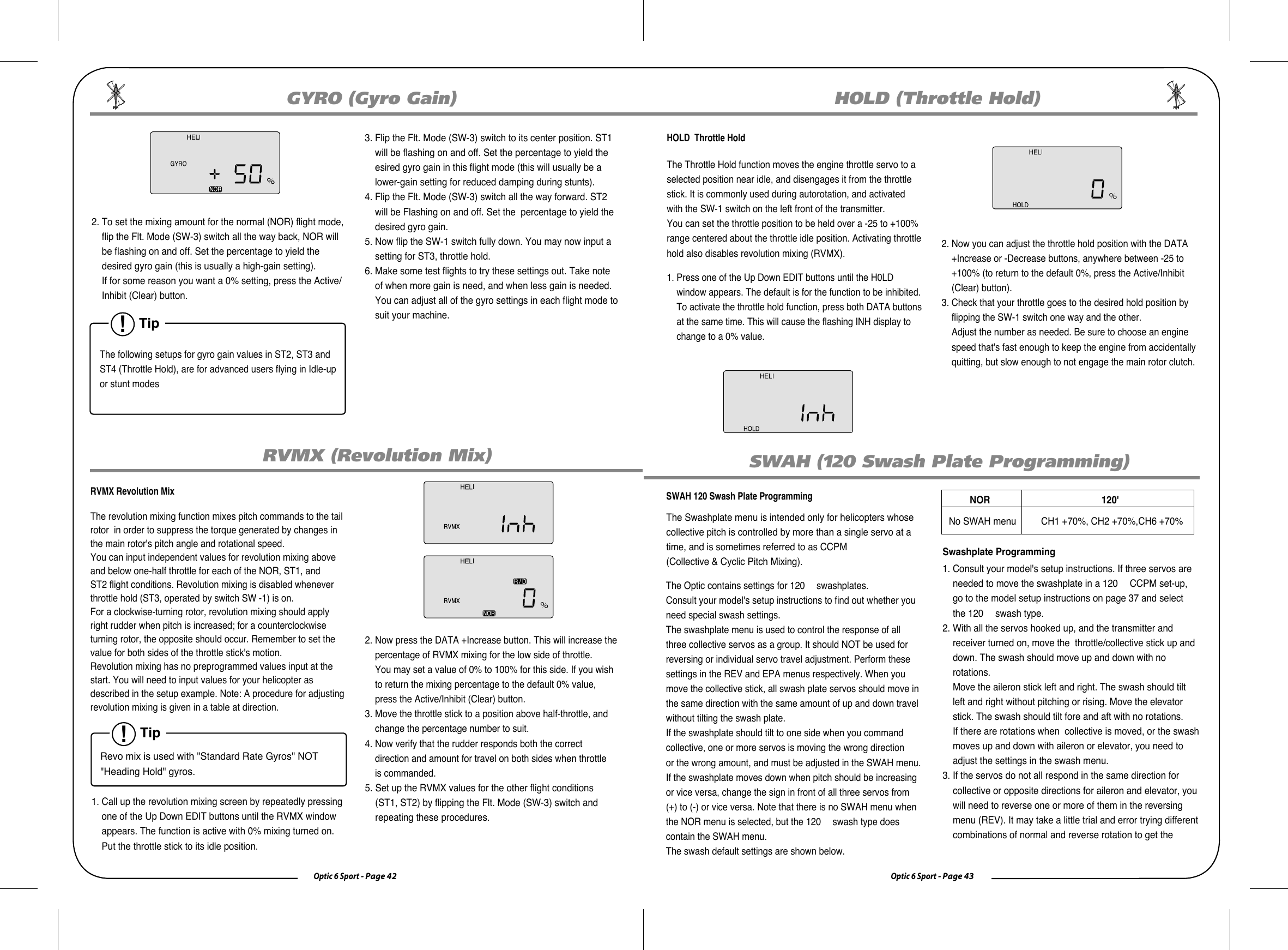
![Optic 6 Sport - Page 38Optic 6 Sport - Page 39Model Setup Menu Programming for HelicopterThis section describes how to use the Optic helicopter functions (model type HELI). Descriptions of the other functions, such as endpoints, dual rates, expo, etc., are contained in the aircraft (ACRO) sectionThe Two Common Types of Power: Electric and Glow There are some subtle, but important differences in the setup methods for glow- versus electric-powered heli's: If your Heli is powered by a glow engine: 1. A servo plugged into the Ch. 3 slot of the receiver controls the carburetor throttle plate of the engine.2. Glow heli's also have their own "on-board" battery to power the receiver, gyro and servos.If your Heli is powered by an electric motor:1. A proportional ESC (Electronic Speed Control) is plugged into the Ch. 3 receiver slot to control the RPM of the motor. The Speed Control may have settings that need to be programmed so check the Speed Controller manual. 2. In smaller electric heli's a large motor battery provides the power for the servos, gyro and receiver through a BEC (battery eliminator circuit) of the ESC (electronic speed control). Larger electric heli's will carry a separate receiver battery to power the servos, receiver and gyro.Model Setup Menu Programming for HelicopterHelicopter Functions Map EPA End Point Adjust (servo travels) 18 D/R Dual Rates 20 EXP Exponential Settings 21 STRM Subtrim(Netural settings) 22 SREV SERVO Reverse 22 P.MIX Programmable Mixer 22 T.CV Throttle Curve 40 P.CV Pitch Curve 41 GYRO Gyro Gain 41 RVMX Revolution Mix 42 HOLD Throttle Hold 43 CUT Throttle Cut 27 SWAH 120 Swash 43 FLT.C Flight condition(NOR, ST1, ST2, ST3) 44Volage/Timer DisplayNormal Display ModeEnd Point Adjust [EPA]Press both Edit ButtonsDual Rate Set [D/R]Exponential [EXP]Sub-Trims [TRM]Servo Reversing [S.REV]Prog.MixThrottle Curve [T.CV]Pitch Curve [P.CV]Gyro setting [GYRO]Revolution [RVMX]Throttle Hold [HOLD]Throttle Cut [CUT]Swash plate [SWAH]Flight Conditions FLT.CModel Setup Menu ProgrammingTo set up the Optic Sport to fly a particular model, you need to get into the radio's model setup menu. In this menu you can program specific control functions and the value (the amount of servo travel) for the particular model helicopter you selected earlier in the initial setup menu. Note: If you have previously set up a model in ACRO, you will notice that in the HELI programming baseline five new functions appear that weren't in the ACRO mode. Throttle Curve, Pitch Curve, Gyro Gain, Revolution Mix and Throttle Hold. All will be explained in the descriptions of these features which appear exclusively in the HELI menu.Now push down both EDIT buttons at the same time. The following menu items-in the order in which they appear-will come on the transmitter's LCD screen as you scroll down the list by pushing down the Right EDIT button:In the upper left-hand corner it will say "HELI" and to the rightthere will be a large number telling you the state of the battery voltage (such as 7.2 v) and a smaller single-digit number indicating the model slot the radio is currently opened to. There will also be a little black box at the bottom of the screen with the symbol "NOR". This indicates that the system is currently in the "normal" flight condition mode which in HELI is also known as the NORMAL curve. Later, we will show you how to activate the flight condition modes, or "idle-up" stunt modes-and it is here on the screen where you will be told which mode is currently active.Go ahead and switch the transmitter on-you are now in the standard operating screen!Tip The Two Fundamental Types of Helicopter's: Fixed Pitch and Collective PitchThere are two fundamental types of model heli's, fixed pitch and collective pitch. The fixed pitch heli is simpler to operate and has fewer moving parts as the motor or engine RPM controls the speed of the "fixed" pitch blades of the heli.For this fixed pitch function you will use the Throttle curve function of the Optic Sport, but not the Pitch curve function.The other, more common, collective pitch setup uses a mix within the electronics of the radio transmitter to combine the throttle RPM with the adjustable "pitch" or angle of the heli's blades. Both Throttle curve and Pitch curve functions of the Optic Sport are used to fine-tune the performance of a collective pitch heli.](https://usermanual.wiki/Hitec-RCD/OPTIC6SP-24G/User-Guide-1204179-Page-20.png)