Hitec RCD RX57MLINK 7 CHANNEL 2.4 GHz TRANSCEIVER User Manual

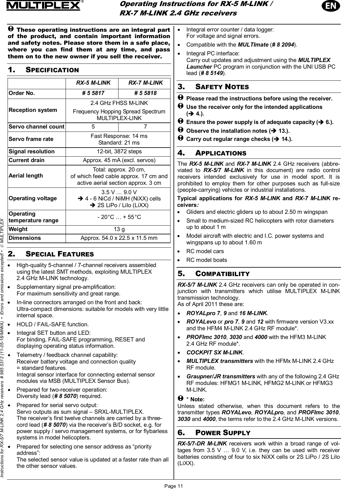
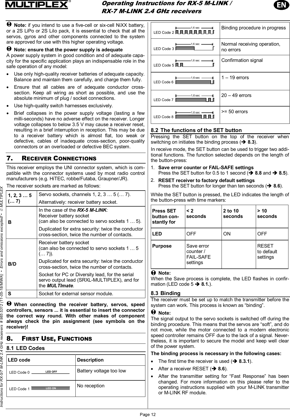
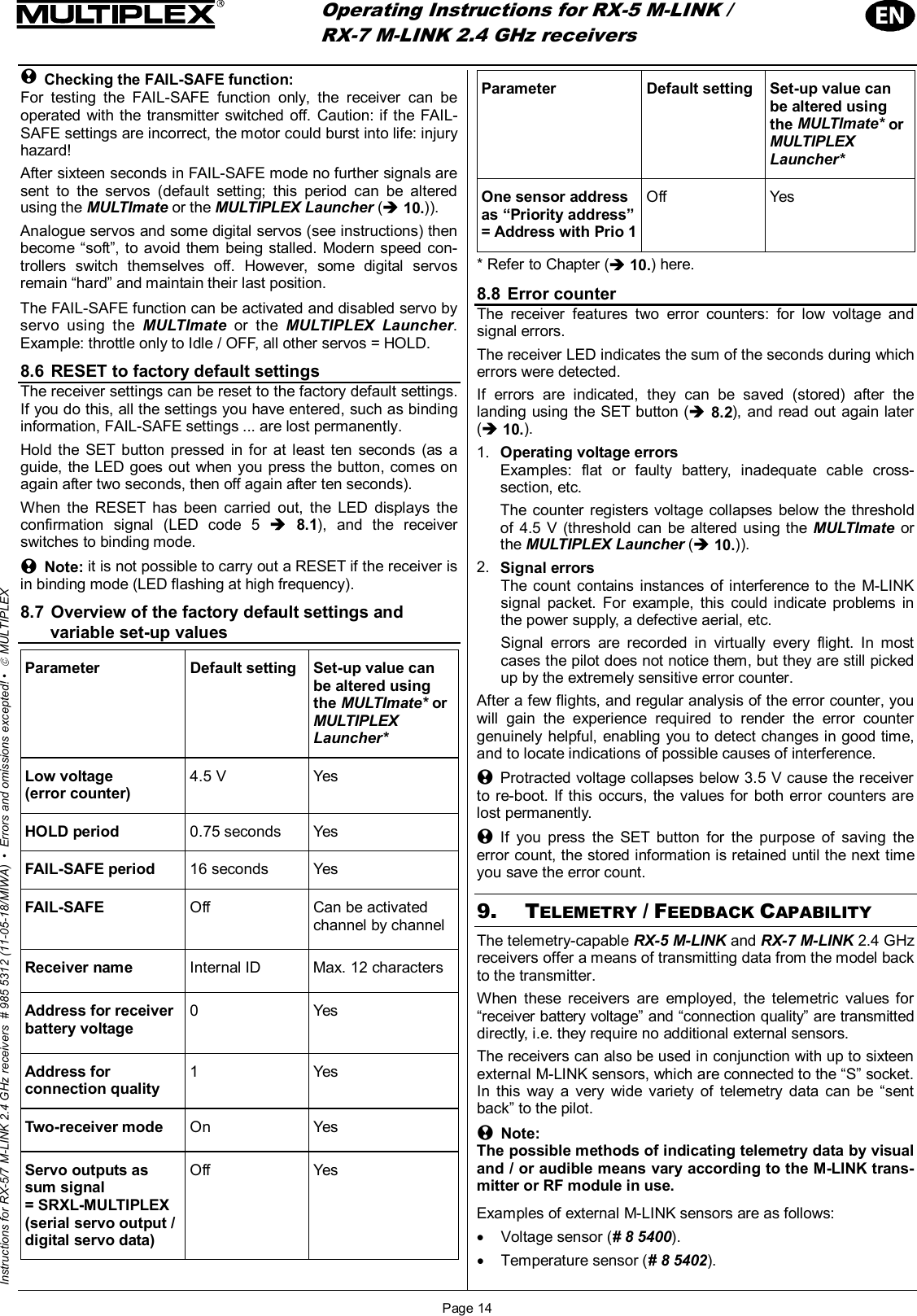
Hitec RCD Inc. 7 CHANNEL 2.4 GHz TRANSCEIVER

User Manual

 Operating Instructions for RX-5 M-LINK /   RX-7 M-LINK 2.4 GHz receivers Page 11 Instructions for RX-5/7 M-LINK 2.4 GHz receivers  # 985 5312 (11-05-18/MIWA)  •  Errors and omissions excepted! •  © MULTIPLEX ! These operating instructions are an integral part of the product, and contain important information and safety notes. Please store them in a safe place, where you can find them at any time, and pass them on to the new owner if you sell the receiver. 1. SPECIFICATION  RX-5 M-LINK RX-7 M-LINK Order No.  # 5 5817  # 5 5818 Reception system 2.4 GHz FHSS M-LINK Frequency Hopping Spread SpectrumMULTIPLEX-LINK Servo channel count  5 7 Servo frame rate  Fast Response: 14 ms Standard: 21 ms Signal resolution  12-bit, 3872 steps Current drain  Approx. 45 mA (excl. servos) Aerial length  Total: approx. 20 cm,  of which feed cable approx. 17 cm and active aerial section approx. 3 cm Operating voltage  3.5 V … 9.0 V Î 4 - 6 NiCd / NiMH (NiXX) cells Î 2S LiPo / LiIo (LiXX) Operating temperature range  - 20 °C … + 55 °C Weight  13 g Dimensions  Approx. 54.0 x 22.5 x 11.5 mm  2. SPECIAL FEATURES •  High-quality 5-channel / 7-channel receivers assembled using the latest SMT methods, exploiting MULTIPLEX  2.4 GHz M-LINK technology. •  Supplementary signal pre-amplification:  For maximum sensitivity and great range. •  In-line connectors arranged on the front and back: Ultra-compact dimensions: suitable for models with very little internal space. •  HOLD / FAIL-SAFE function. •  Integral SET button and LED:   For binding, FAIL-SAFE programming, RESET and  displaying operating status information. •  Telemetry / feedback channel capability: Receiver battery voltage and connection quality  = standard features. Integral sensor interface for connecting external sensor modules via MSB (MULTIPLEX Sensor Bus). •  Prepared for two-receiver operation: Diversity lead (# 8 5070) required. •  Prepared for serial servo output: Servo outputs as sum signal – SRXL-MULTIPLEX.  The receiver’s first twelve channels are carried by a three-cord lead (# 8 5070) via the receiver’s B/D socket, e.g. for power supply / servo management systems, or for flybarless systems in model helicopters.  •  Prepared for selecting one sensor address as “priority address”:  The selected sensor value is updated at a faster rate than all the other sensor values. •  Integral error counter / data logger: For voltage and signal errors. •  Compatible with the MULTImate (# 8 2094). •  Integral PC interface:  Carry out updates and adjustment using the MULTIPLEX Launcher PC program in conjunction with the UNI USB PC lead (# 8 5149). 3. SAFETY NOTES ! Please read the instructions before using the receiver. ! Use the receiver only for the intended applications  (Î 4.). ! Ensure the power supply is of adequate capacity (Î 6.). ! Observe the installation notes (Î 13.). ! Carry out regular range checks (Î 14.). 4. APPLICATIONS The RX-5 M-LINK and RX-7 M-LINK 2.4 GHz receivers (abbre-viated to RX-5/7 M-LINK in this document) are radio control receivers intended exclusively for use in model sport. It is prohibited to employ them for other purposes such as full-size (people-carrying) vehicles or industrial installations. Typical applications for RX-5 M-LINK and RX-7 M-LINK re-ceivers: •  Gliders and electric gliders up to about 2.50 m wingspan •  Small to medium-sized RC helicopters with rotor diameters up to about 1 m •  Model aircraft with electric and I.C. power systems and wingspans up to about 1.60 m • RC model cars • RC model boats 5. COMPATIBILITY RX-5/7 M-LINK 2.4 GHz receivers can only be operated in con-junction with transmitters which utilise MULTIPLEX M-LINK transmission technology.    As of April 2011 these are: • ROYALpro 7, 9 and 16 M-LINK. • ROYALevo or pro 7, 9 and 12 with firmware version V3.xx and the HFM4 M-LINK 2.4 GHz RF module*. • PROFImc 3010, 3030 and 4000 with the HFM3 M-LINK  2.4 GHz RF module*. • COCKPIT SX M-LINK. • MULTIPLEX transmitters with the HFMx M-LINK 2.4 GHz RF module. • Graupner/JR transmitters with any of the following 2.4 GHz RF modules: HFMG1 M-LINK, HFMG2 M-LINK or HFMG3 M-LINK. ! * Note: Unless stated otherwise, when this document refers to the transmitter types ROYALevo, ROYALpro, and PROFImc 3010, 3030 and 4000, the terms refer to the 2.4 GHz M-LINK versions. 6. POWER SUPPLY RX-5/7-DR M-LINK receivers work within a broad range of vol-tages from 3.5 V … 9.0 V, i.e. they can be used with receiver batteries consisting of four to six NiXX cells or 2S LiPo / 2S LiIo (LiXX).
 Operating Instructions for RX-5 M-LINK /   RX-7 M-LINK 2.4 GHz receivers Page 12 Instructions for RX-5/7 M-LINK 2.4 GHz receivers  # 985 5312 (11-05-18/MIWA)  •  Errors and omissions excepted! •  © MULTIPLEX ! Note: if you intend to use a five-cell or six-cell NiXX battery, or a 2S LiPo or 2S LiIo pack, it is essential to check that all the servos, gyros and other components connected to the system are approved for use with this higher operating voltage. ! Note: ensure that the power supply is adequate A power supply system in good condition and of adequate capa-city for the specific application plays an indispensable role in the safe operation of any model: •  Use only high-quality receiver batteries of adequate capacity. Balance and maintain them carefully, and charge them fully. •  Ensure that all cables are of adequate conductor cross-section. Keep all wiring as short as possible, and use the absolute minimum of plug / socket connections. •  Use high-quality switch harnesses exclusively. •  Brief collapses in the power supply voltage (lasting a few milli-seconds) have no adverse effect on the receiver. Longer voltage collapses to below 3.5 V may cause a receiver reset, resulting in a brief interruption in reception. This may be due to a receiver battery which is almost flat, too weak or defective, cables of inadequate cross-section, poor-quality connectors or an overloaded or defective BEC system. 7. RECEIVER CONNECTIONS This receiver employs the UNI connector system, which is com-patible with the connector systems used by most radio control manufacturers (e.g. HiTEC, robbe/Futaba, Graupner/JR). The receiver sockets are marked as follows: 1, 2, 3 … 5 (… 7) Servo sockets, channels 1, 2, 3 … 5 (… 7). Alternatively: receiver battery socket. B In the case of the RX-5 M-LINK: Receiver battery socket   (can also be connected to servo sockets 1 … 5). Duplicated for extra security: twice the conductor cross-section, twice the number of contacts. B/D Receiver battery socket  (can also be connected to servo sockets 1 … 5 (… 7)).  Duplicated for extra security: twice the conductor cross-section, twice the number of contacts. Socket for PC or Diversity lead, for the serial  servo output lead (SRXL-MULTIPLEX), and for the MULTImate. S  Socket for external sensor module.  ! When connecting the receiver battery, servos, speed controllers, sensors ... it is essential to insert the connector the correct way round. With other makes of component always check the pin assignment (see symbols on the receiver)! 8. FIRST USE, FUNCTIONS 8.1 LED Codes     LED code  Description  LED Code 0 LED OFF  Battery voltage too low  LED Code 1 LED ON  No reception  LED Code 21,6 sec  Binding procedure in progress  1,6 secLED Code 3  Normal receiving operation,  no errors  1,6 secLED Code 5  Confirmation signal LED Code 61,6 sec  1 – 19 errors LED Code 71,6 sec  20 – 49 errors LED Code 81,6 sec  >= 50 errors   8.2  The functions of the SET button Pressing the SET button on the top of the receiver when switching on initiates the binding process (Î 8.3). In receive mode, the SET button can be used to trigger two addi-tional functions. The function selected depends on the length of the button-press:   1.  Save error counter or FAIL-SAFE settings    Press the SET button for 0.5 to 1 second (Î 8.8 and Î 8.5).  2.  RESET receiver to factory default settings    Press the SET button for longer than ten seconds (Î 8.6). While the SET button is pressed, the LED indicates the length of the button-press with time markers:  Press SET button con-stantly for < 2  seconds 2 to 10 seconds > 10  seconds LED   OFF ON OFF Purpose  Save error counter /  FAIL-SAFE settings  RESET  to default settings ! Note: When the Save process is complete, the LED flashes in confir-mation (LED code 5 Î 8.1.). 8.3 Binding The receiver must be set up to match the transmitter before the system can work. This process is known as “binding”. ! Note: The signal output to the servo sockets is switched off during the binding procedure. This means that the servos are “soft”, and do not move, while the motor connected to a modern electronic speed controller remains OFF due to the lack of a signal. Never-theless, it is important to secure the model and keep well clear of the power system. The binding process is necessary in the following cases: •  The first time the receiver is used (Î 8.3.1). •  After a receiver RESET (Î 8.6). •  After the transmitter setting for “Fast Response” has been changed. For more information on this please refer to the operating instructions supplied with your M-LINK transmitter or M-LINK RF module.
 Operating Instructions for RX-5 M-LINK /   RX-7 M-LINK 2.4 GHz receivers Page 13 Instructions for RX-5/7 M-LINK 2.4 GHz receivers  # 985 5312 (11-05-18/MIWA)  •  Errors and omissions excepted! •  © MULTIPLEX •  After the transmitter setting for the transmitted frequency range has been changed. For more information on this please refer to the operating instructions supplied with your transmitter or M-LINK RF module (“France mode”). •  If the receiver is to be operated in conjunction with a different M-LINK transmitter. 8.3.1  Sequence of the binding procedure 1.  The first step is always to set the transmitter and receiver to Binding mode: •  Move the transmitter and the receiver aerial very close to each other. •  Switch the transmitter ON in binding mode.   (see the operating instructions supplied with your M-LINK transmitter or M-LINK RF module). • Switch the RX-5/7 M-LINK receiver ON in binding mode: •  Use a pointed object to press and hold the SET button   on the top of the receiver (Î 8.2). •   Switch the receiver ON, or connect the battery: ⇒  The binding procedure runs, the receiver LED flashes at high frequency   (LED code 2 Î 8.1). •   Now release the SET button. ! Note: the binding process starts automatically when the receiver is used for the first time, and after a RESET - even if you have not pressed the SET button. 2.  Once the transmitter and receiver are bound to each other, both switch automatically to normal operation (Î 8.4):  ⇒ The LED on the receiver flashes slowly      (LED code 3 Î 8.1). ! Note: in most cases the binding process only takes a few seconds. 8.3.2  Binding: locating and correcting faults Fault:  During the binding process the receiver LED continues to flash at a high rate after several seconds. Cause:  No M-LINK signal of adequate strength detected. Remedy: •  Reduce the distance between your transmitter and the receiver aerial. •  Ensure that your transmitter is switched ON in binding mode. •  Repeat the binding procedure. 8.4 Switching the receiver ON and OFF  in normal operations 8.4.1  Sequence of switching ON and OFF To switch the M-LINK RC system ON, please use this procedure: 1.  Switch the transmitter ON. 2.  Switch the receiver ON. The receiver LED flashes slowly and evenly  (LED code 3 Î 8.1): ⇒  An M-LINK signal is being received,   the RC system is ready for use. To switch the M-LINK RC system OFF, please use this procedure: 1.  Switch the receiver OFF. 2.  Now switch the transmitter OFF.  8.4.2  Locating and correcting faults when switching ON Fault:   The receiver LED lights up constantly when switched on (LED code 1 Î 8.1), but does not flash. Cause: No M-LINK signal detected. Remedy: •  Is the transmitter switched on? •  Is the transmitter generating an M-LINK signal?  •  Are the transmitter and receiver bound to each other? •  Have you carried out a receiver RESET (Î 8.2, Î 8.6)? •  Have you made changes to the setting for “Fast Response” (Î 8.3) or “France mode” (Î 8.3)? Error: The receiver LED stays off after switching on    (LED code 0 Î 8.1). Cause:  The operating voltage (battery voltage) is too low. Remedy: •  Recharge the receiver battery or drive / flight battery. 8.5 HOLD and FAIL-SAFE If no signal is picked up, or if the received data is corrupt, the last valid information is passed on to the servos in order to bridge the signal loss (HOLD mode). If interference should occur and FAIL-SAFE has been invoked, the servos (...) run to a previously defined position at the end of the HOLD period. FAIL-SAFE mode ends as soon as error-free signals are picked up again. The factory default setting for the HOLD period is 0.75 seconds. This period can be adjusted to meet personal requirements using the MULTImate (Î 10.) or the PC program MULTIPLEX Launcher (Î 10.). FAIL-SAFE is switched OFF in the receiver’s default state (as delivered), and after a RESET. FAIL-SAFE is activated using the SET button on the receiver, or - in the case of certain trans-mitters - “by radio”. If you wish to disable FAIL-SAFE again, the receiver must be reset to the default state (RESET Î 8.6). After a RESET you must repeat the binding procedure (Î 8.3)! !  Note: always activate FAIL-SAFE! For safety reasons we recommend that you always activate FAIL-SAFE, and ensure that the selected FAIL-SAFE settings will cause the model to take up as safe an attitude as possible (e.g. motor idle / electric motor OFF, control surfaces neutral, landing flaps deployed, tow-release open, …). Selecting the FAIL-SAFE settings: 1.  The receiver LED must not display any errors   (LED code 3 Î 8.1).   If it does: switch the receiver OFF, then ON again. 2   Use your transmitter to move all the servos (and the speed controller) to your preferred FAIL-SAFE positions. Press the SET button briefly (0.5 to 1 second). The FAIL-SAFE posi-tions are now stored for all servo channels, and the LED flashes the confirmation signal (LED code 5 Î 8.1). Testing the FAIL-SAFE positions:   Move the sticks to positions other than the FAIL-SAFE settings, and then switch the transmitter OFF: the servos should go into HOLD mode briefly (0.75 seconds), and then move to the FAIL-SAFE positions which you previously selected. The FAIL-SAFE positions must always be checked and updated when necessary, e.g. when you install the receiver in a new model.
 Operating Instructions for RX-5 M-LINK /   RX-7 M-LINK 2.4 GHz receivers Page 14 Instructions for RX-5/7 M-LINK 2.4 GHz receivers  # 985 5312 (11-05-18/MIWA)  •  Errors and omissions excepted! •  © MULTIPLEX ! Checking the FAIL-SAFE function: For testing the FAIL-SAFE function only, the receiver can be operated with the transmitter switched off. Caution: if the FAIL-SAFE settings are incorrect, the motor could burst into life: injury hazard! After sixteen seconds in FAIL-SAFE mode no further signals are sent to the servos (default setting; this period can be altered using the MULTImate or the MULTIPLEX Launcher (Î 10.)). Analogue servos and some digital servos (see instructions) then become “soft”, to avoid them being stalled. Modern speed con-trollers switch themselves off. However, some digital servos remain “hard” and maintain their last position. The FAIL-SAFE function can be activated and disabled servo by servo using the MULTImate  or the MULTIPLEX Launcher. Example: throttle only to Idle / OFF, all other servos = HOLD. 8.6 RESET to factory default settings The receiver settings can be reset to the factory default settings. If you do this, all the settings you have entered, such as binding information, FAIL-SAFE settings ... are lost permanently. Hold the SET button pressed in for at least ten seconds (as a guide, the LED goes out when you press the button, comes on again after two seconds, then off again after ten seconds). When the RESET has been carried out, the LED displays the confirmation signal (LED code 5 Î 8.1), and the receiver switches to binding mode. ! Note: it is not possible to carry out a RESET if the receiver is in binding mode (LED flashing at high frequency). 8.7 Overview of the factory default settings and variable set-up values Parameter  Default setting  Set-up value can be altered using the MULTImate* orMULTIPLEX Launcher* Low voltage  (error counter) 4.5 V  Yes HOLD period  0.75 seconds  Yes FAIL-SAFE period  16 seconds  Yes FAIL-SAFE  Off  Can be activated channel by channel Receiver name  Internal ID  Max. 12 characters Address for receiver battery voltage 0  Yes Address for connection quality  1 Yes Two-receiver mode  On Yes Servo outputs as sum signal  = SRXL-MULTIPLEX (serial servo output / digital servo data) Off Yes Parameter  Default setting  Set-up value can be altered using the MULTImate* orMULTIPLEX Launcher* One sensor address as “Priority address”= Address with Prio 1Off Yes * Refer to Chapter (Î 10.) here. 8.8 Error counter The receiver features two error counters: for low voltage and signal errors. The receiver LED indicates the sum of the seconds during which errors were detected. If errors are indicated, they can be saved (stored) after the landing using the SET button (Î 8.2), and read out again later (Î 10.). 1.  Operating voltage errors Examples: flat or faulty battery, inadequate cable cross-section, etc.    The counter registers voltage collapses below the threshold of 4.5 V (threshold can be altered using the MULTImate or the MULTIPLEX Launcher (Î 10.)). 2.  Signal errors The count contains instances of interference to the M-LINK signal packet. For example, this could indicate problems in the power supply, a defective aerial, etc. Signal errors are recorded in virtually every flight. In most cases the pilot does not notice them, but they are still picked up by the extremely sensitive error counter. After a few flights, and regular analysis of the error counter, you will gain the experience required to render the error counter genuinely helpful, enabling you to detect changes in good time, and to locate indications of possible causes of interference. ! Protracted voltage collapses below 3.5 V cause the receiver to re-boot. If this occurs, the values for both error counters are lost permanently. ! If you press the SET button for the purpose of saving the error count, the stored information is retained until the next time you save the error count.  9. TELEMETRY / FEEDBACK CAPABILITY The telemetry-capable RX-5 M-LINK and RX-7 M-LINK 2.4 GHz receivers offer a means of transmitting data from the model back to the transmitter. When these receivers are employed, the telemetric values for “receiver battery voltage” and “connection quality” are transmitted directly, i.e. they require no additional external sensors. The receivers can also be used in conjunction with up to sixteen external M-LINK sensors, which are connected to the “S” socket. In this way a very wide variety of telemetry data can be “sent back” to the pilot. ! Note: The possible methods of indicating telemetry data by visual and / or audible means vary according to the M-LINK trans-mitter or RF module in use. Examples of external M-LINK sensors are as follows: • Voltage sensor (# 8 5400). • Temperature sensor (# 8 5402).
 Operating Instructions for RX-5 M-LINK /   RX-7 M-LINK 2.4 GHz receivers Page 15 Instructions for RX-5/7 M-LINK 2.4 GHz receivers  # 985 5312 (11-05-18/MIWA)  •  Errors and omissions excepted! •  © MULTIPLEX • Current sensor:   150 A (# 8 5405) or    35 A ((# 8 5403) or (8 5404)). •  Rev count sensor:   Optical (# 8 5414) or magnetic (# 8 5415). •  Vario / altitude sensor (# 8 5416).  • GPS (# 8 5417). For more information on connecting and operating the various sensor types and their features (measurement range, addres-sing, warning threshold settings, display facilities for minimum, average or maximum values, in some cases activation of a second measurement channel, ...) please refer to the instructions supplied with the sensors and / or the MULTImate. 10. MULTIMATE AND  MULTIPLEX LAUNCHER PC PROGRAM All MULTIPLEX M-LINK receivers are based on modern micro-controllers (FLASH technology). In the case of most M-LINK receiver types (see the operating instructions supplied with your receiver) it is also possible to connect the unit to the MULTImate (# 8 2094) and / or to a PC or notebook computer using the PC connecting lead (# 8 5149); the PC program MULTIPLEX Launcher can then be used. The MULTIPLEX Launcher PC program is available as a free download from the MULTIPLEX website (www.multiplex-rc.de). This program, and the MULTImate (V1.50 or higher), opens up the following facilities: •  Availability of expanded receiver options, such as freely variable HOLD and FAIL-SAFE period, individual FAIL-SAFE settings can be activated and adjusted channel by channel, … •  Error counter / error memory read-out:   The error count can be read out separately for signal errors and operating voltage errors. •  Unrestricted sensor address assignment for the receiver battery voltage and for connection quality (0 - 15). •  Receiver name assignment (max. 12 characters).  •  Switching the following options on and off: “Two-receiver mode” (Î 11.) and serial servo output (digital servo data / SRXL-MULTIPLEX) (Î 12.). •  Setting one sensor address as “priority address”:   The selected sensor value is updated at a higher rate than all the other sensor values (Î 13.).  The MULTIPLEX Launcher also allows: • Firmware updates: Keep your receiver up-to-date at all times. ! Note: We recommend that you update your MULTImate or the MULTI-PLEX Launcher at regular intervals to ensure that you can exploit all the current features of your receiver and the con-nected components generally. 11. TWO-RECEIVER MODE What is known as “two-receiver mode” is possible with the MULTIPLEX  RX-5 M-LINK and RX-7 M-LINK 2.4 GHz M-LINK receivers: In this mode two M-LINK receivers are inter-connected using a Diversity lead (# 8 5070). With this arrangement a total of two or even three receive cir-cuits operate in parallel:  The two or three receive circuits incorporated in the two receiver cases pick up and analyse the signals (“double diversity” or “triple diversity”). This type of diversity can also be described as “two-receiver mode”. Since the orientation of the two or three receiver aerials is different, this arrangement provides a further improvement in receive performance, since it minimises directional aerial effects. This means that at least one receiver aerial has a “good view” of the transmitter regardless of the model’s attitude. Two-receiver mode therefore provides a wider safety margin. ! Tip: you can also inter-connect different types of M-LINK receiver, provided that they are capable of two-receiver mode (e.g. 1 x RX-16-DR pro M-LINK and 1 x RX-5 M-LINK). Information concerning suitability for two-receiver mode can be found in the operating instructions provided with the various M-LINK receivers. This is the procedure for re-activating two-receiver mode: ! Note: M-LINK receivers are set to two-receiver mode by default. For this reason you can skip steps 1. – 3. and go directly to step 4. 1.  Re-activating using the MULTImate: •  At the menu point “4-7 B/D output“ / “4-7 Ausgabe B/D“  (= output B/D) select the following option:  “MPX 2-Receiver“ / “MPX 2-Empfänger“  (= MPX Two-receiver mode). •  Select the menu point:  “4-10 Send data“ / “4-10 Dat. senden“ (= Send data)  and hold the 3-D digi-adjuster pressed in:  Î the MULTImate displays the following:    “please wait…“ / “bitte warten…“ (= please wait). •  Release the 3-D digi-adjuster:  Î When the send process is complete, the screen  displays “--> OK!“ (= complete!). •  Disconnect the receiver, switch off the MULTImate. 2.  Re-activating using the MULTIPLEX Launcher: • At “More settings Î Options…“ / “Weitere Einstellungen Î Optionen…“ (= More settings Î Options) select the following menu point:  “MULTIPLEX Two-Receiver-Mode“ / “MULTIPLEX Zwei-Empfänger-Betrieb“  (= MULTIPLEX two-receiver mode). •  Click on the “Accept“ / “Übernehmen“ button (= Accept). •  Click on the “Send data“ / “Daten senden“ button (= Send data). •  Click on the “Close“ / “Beenden“ button (= Finish). • Close MULTIPLEX Launcher, disconnect the receiver. 3.  You may need to carry out the steps described under 1. or 2. on the second M-LINK receiver in order to activate two-receiver mode. 4.   Inter-connect the two M-LINK receivers by the B/D sockets using the three-cord Diversity lead (# 8 5070). Please refer to the operating instruction supplied with the Diversity lead. ! Take care to connect the lead correctly, i.e. the con-nectors must be correctly orientated, and the pin assign-ment must be compatible (see symbols on the receiver)!
 Operating Instructions for RX-5 M-LINK /   RX-7 M-LINK 2.4 GHz receivers Page 16 Instructions for RX-5/7 M-LINK 2.4 GHz receivers  # 985 5312 (11-05-18/MIWA)  •  Errors and omissions excepted! •  © MULTIPLEX 12. SERIAL SERVO OUTPUT –   SRXL-MULTIPLEX RX-5/7 M-LINK receivers offer the facility to use the servo out-puts as a sum signal (serial servo output = SRXL-MULTIPLEX): The receiver’s first twelve channels are carried by a three-core lead (# 8 5070) via the receiver’s B/D socket. Applications: •  Power supply / servo management systems, or •  Flybarless systems on model helicopters. ! Note: SRXL-MULTIPLEX is switched off by default on M-LINK recei-vers, and can be activated using the MULTIPLEX MULTImate or the MULTIPLEX Launcher PC program in conjunction with the UNI USB PC lead (# 8 5149). This is the procedure for activating serial servo output: 1. Activating using the MULTImate: •  At the menu point “4-7 B/D output“ / “4-7 Ausgabe B/D“  (= Output B/D) select the following option:  “Digit. Servodata“ / “Dig. Servodaten“  (= Digital servo data). •  Select the menu point:  “4-10 Send data“ / “4-10 Dat. senden“ (= Send data)  and hold the 3-D digi-adjuster pressed in:   Î The MULTImate screen displays:    “please wait…“ / “bitte warten…“ (= please wait). •  Release the 3-D digi-adjuster:  Î When the Send process is complete, the screen displays “--> OK!“ (= complete!). •  Disconnect the receiver, switch off the MULTImate. 2. Activating using the MULTIPLEX Launcher: • At “More settings Î Options“ / “Weitere Einstellungen Î Optionen…“  (= More settings Î Options) select the following menu point:  “Digital servodata“ / “Digitale Servodaten“  (= Digital servo data). •  Click on the “Accept“ / „Übernehmen“ button (= Accept). •  Click on the „Send data“ / “Daten senden“ button (= Send data). •  Click on the “Close“ / “Beenden“ button (= Finish). • Close MULTIPLEX Launcher, disconnect the receiver. 3.  Connect the three-core lead (# 8 5070) to the receiver’s B/D socket. 4.  Connect the lead to the power supply / servo management system, or to the flybarless system (see the operating instructions supplied with these devices). ! Take care to connect the lead correctly, i.e. the con-nectors must be correctly orientated, and - especially when using non-MULTIPLEX products - the pin assign-ment must be compatible. Be sure to check the symbols on the M-LINK receiver, and on the non-MULTIPLEX product if present. Refer to the operating instructions of the non-MULTIPLEX device, and ask the manufacturer if you are in any doubt!    13. SELECTING ONE SENSOR ADDRESS AS “PRIORITY ADDRESS” The telemetry-capable RX-5/7 M-LINK receivers permit the user to define any one of the sensor addresses (0 … 15) as a “priority address”: This one selected sensor value is then updated at a higher rate than all the other sensor values. Typical application: “Vario”:    The audio output for climb and descent, and the associated on-screen display, are updated more frequently than the other sensor values, and are therefore generated without delay. ! Note: The “Priority address” option is switched off by default on M-LINK receivers, and can be activated using the MULTIPLEX MULTI-mate or the MULTIPLEX Launcher PC program in conjunction with the UNI USB PC lead (# 8 5149). This is the procedure for activating the priority address: 1. Activating using the MULTImate: •  At the menu point “4-6 Sensor addr.“ / “4-6 Sensoradr.“  (= Sensor address) select the option:  “4-6 Prio address“ / “4-6 Prio Adresse“  (= Priority address). •  Hold the 3-D digi-adjuster pressed in:  Î The MULTImate displays: “L   0“. •  Release the 3-D digi-adjuster. •  Press the 3-D digi-adjuster briefly, and select the priority address (0 … 15). •  Press the 3-D digi-adjuster briefly. •  Switch to the menu:  “4-6 Go back …to RX M-LINK“ /  “4-6 Zurück …zu RX M-LINK“  (= back … to RX M-LINK) and confirm by pressing the 3-D digi-adjuster. •  Select the menu point: “4-10 Send data“ / “4-10 Dat. senden“  (= Send data) and hold the 3-D digi-adjuster pressed in:   Î The MULTImate displays:        “please wait…“ / “bitte warten…“ (= please wait). •  Release the 3-D digi-adjuster:  Î When the Send process is complete, the screen displays “--> OK!“ (= complete!). •  Disconnect the receiver, switch off the MULTImate. 2. Activating using the MULTIPLEX Launcher: •  At “Sensor addresses“ / “Sensorparameter“  (= Sensor address) auswählen:  “Address w/prio 1:“ / “Adresse mit Prio 1:“ (= Address with priority 1). •  Select the “Address“ / “Adresse“ (= Address) check-box, and enter the desired address (0 … 15). •  Click on the “Accept“ / “Übernehmen“ button (= Accept). •  Click on the “Send data“ / “Daten senden“ button (= Send data). •  Click on the “Close“ / “Beenden“ button  (= Finish). • Close the MULTIPLEX Launcher, disconnect the receiver.
 Operating Instructions for RX-5 M-LINK /   RX-7 M-LINK 2.4 GHz receivers Page 17 Instructions for RX-5/7 M-LINK 2.4 GHz receivers  # 985 5312 (11-05-18/MIWA)  •  Errors and omissions excepted! •  © MULTIPLEX This is the procedure for disabling the priority address: 1.  Disabling using the MULTImate: •  At the menu point “4-6 Sensor addr.“ / “4-6 Sensoradr.“  (= Sensor address) select the option:  “4-6 Prio address“ / “4-6 Prio Adresse“  (= Priority address).  ! Note: The second line of the screen displays the selected priority address. •  Hold the 3-D digi-adjuster pressed in:  Î The screen entry in the second line changes to:   “L  off“ / “L   aus“ (= L   off). •  Switch to the menu:  “4-6 Go back …to RX M-LINK“ /  “4-6 Zurück …zu RX M-LINK“  (= back … to RX M-LINK) and confirm by pressing the 3-D digi-adjuster. •  Select the menu point:  “4-10 Send data“ / “4-10 Dat. senden“  (= Send data) and hold the 3-D digi-adjuster pressed in:   Î The MULTImate displays:    “please wait…“ / “bitte warten…“ (= please wait). •  Release the 3-D digi-adjuster:  Î When the Send process is complete, the screen displays “--> OK!“ (= complete!). •  Disconnect the receiver, switch off the MULTImate. 2.  Disabling using the MULTIPLEX Launcher: •  At “Sensor addresses“ / “Sensorparameter“  (= Sensor parameters) auswählen:  “Address w/prio 1:“ / “Adresse mit Prio 1:“ (= Address with priority 1). •  Clear (erase) the tick in the “Address“ / “Adresse“ check-box (= Address). •  Click on the “Accept“ / “Übernehmen“ button  (= Accept). •  Click on the “Send data“ / “Daten senden“ button (= Send data). •  Click on the “Close“ / “Beenden“ button  (= Finish). • Close the MULTIPLEX Launcher, disconnect the receiver. 14. INSTALLATION NOTES •  Protect your receiver from vibration, especially in models powered by an internal-combustion engine (e.g. pack it loosely in foam). •  Locate the receiver at least 150 mm away from electric mo-tors, petrol engine ignition systems and any other electronic components such as speed controllers for electric motors and drive batteries. Keep the aerial away from these components. •  Install the receiver in the model in such a way that the aerial is as far away as possible from all conductive materials. •  If your model’s fuselage consists of conductive materials (e.g. carbon fibre), then the aerial must be installed in such a way that the active part of the aerial (the final 30 mm) is located outside the model. •  Do not deploy the receiver aerial inside or on model com-ponents which are laminated or reinforced with electrically conductive materials (metal foil, carbon fibre, metallic paints etc.), as they have a shielding effect. •  Do not shorten or extend the aerial or the aerial feed cable. Never attempt to replace or repair the aerial or aerial cable! •  Do not deploy the aerial parallel to servo leads, high-current cables or electrically conductive parts (e.g. pushrods). •  Keep to the recommended installed arrangements (Î 20., sketches A - C)! •  High-current cables, e.g. those attached to the speed con-troller, motor and flight battery, should be kept as short as possible. •  If you are using a diode-based battery backer, always install a PeakFilter (# 8 5180). •  Reception quality can be optimised by fitting a special ferrite ring (# 8 5146) or suppressor filter lead (# 8 5057) in the speed controller cable. It is also advisable to fit effective suppressors to conventional (brushed) electric motors (not brushless types) (e.g. use the suppressor set # 8 5020). 15. RANGE CHECKING Regular range checks are very important - even when using a 2.4 GHz system - in order to ensure reliable operation of the radio control system, and to enable you to detect sources of interference in good time. This applies in particular: •  Before the use of new or changed components, or existing components in a new or modified arrangement. •  Before re-using radio control system components which were previously involved in a crash or a hard landing. •  If you have encountered problems on a previous flight. Important: •  Always ask a second person to help you with your range check, so that one of you can secure and observe the model. •  If possible, carry out the range check when no other trans-mitters are operating. Carrying out the range check: 1. Select “range-check mode” on your transmitter (see the operating instructions supplied with the transmitter or RF module). There must be line-of-sight connection between the trans-mitter and receiver aerials (i.e. the model) during the range check. Keep the transmitter and the model about one metre above ground during the range check. 2.  When checked with reduced transmitter power, the range of the RX-5/7 M-LINK receiver must be 40 metres. You have reached the range limit when the servos start to move jerkily. If your transmitter features an automatic servo test facility, we recommend that you activate it for one control function (e.g. rudder). This sets up a steady movement of the servo, and enables you to detect the limit of range clearly. Important: Carry out the first range check with the motor switched off. Turn the model into all attitudes, and attempt to optimise reception by changing the position of the two aerials. For the second range check, run the motor at varying speeds and check that the effective range is not significantly reduced. If there is a marked reduction, locate and eliminate the cause of the interference (caused by the motor, the arrangement of the receiving system and power supply, vibration, etc.).
 Operating Instructions for RX-5 M-LINK /   RX-7 M-LINK 2.4 GHz receivers Page 18 Instructions for RX-5/7 M-LINK 2.4 GHz receivers  # 985 5312 (11-05-18/MIWA)  •  Errors and omissions excepted! •  © MULTIPLEX 16. EXCHANGING THE AERIALS The standard aerial feed cable attached to the RX-5/7 M-LINK receiver types is long enough for most applications. If you require longer or shorter aerial feed cables, please contact the MULTIPLEX Service Department or any MULTIPLEX Ser-vice Centre, as they stock cables of different lengths, and will gladly quote an individual price for modifying your receiver to professional standards. ! Caution: never attempt to exchange the aerial yourself! Changing the aerial to a professional standard requires special tools as well as appropriate expertise. Ignoring this warning may have an adverse effect on the receiver’s reception quality. ! Caution: if the active part of the aerial (the final 30 mm) should be damaged, the aerial must be replaced by the MULTIPLEX Service Department or a MULTIPLEX Service Centre; this also applies if the aerial feed cable is damaged. 17. CE CONFORMITY DECLARATION This device has been assessed and approved in accordance with European harmonised directives. This means that you possess a product whose design and construction fulfil the protective aims of the European Com-munity designed to ensure the safe operation of equipment. The detailed CE conformity declaration can be downloaded in the form of a PDF file from the Internet under www.multiplex-rc.de. It is located in the DOWNLOADS area under PRODUKT-INFOS. 18. DISPOSAL NOTES Electrical equipment marked with the cancelled waste bin symbol must not be discarded in the standard household waste; instead it should be taken to a suitable specialist disposal system. In the countries of the EU (European Union) electrical equipment must not be discarded via the normal domestic refuse system (WEEE - Waste of Electrical and Electronic Equipment, Directive 2002/96/EG). You can take unwanted equipment to your nearest local authority waste collection point or recycling centre. There the equipment will be disposed of correctly and at no cost to you. By returning your unwanted equipment you can make an important contribution to the protection of the environment! 19. GUARANTEE / LIABILITY EXCLUSION The company MULTIPLEX Modellsport GmbH & Co.KG accepts no liability of any kind for loss, damage or costs which are due to the incorrect use and operation of this product, or which are connected with such operation in any way. Unless the law expressly states otherwise, the liability on the part of MULTI-PLEX Modellsport GmbH & Co.KG to pay damages, regardless of the legal argument employed, is limited to the invoice value of those products supplied by MULTIPLEX Modellsport GmbH & Co.KG which were directly involved in the event in which the damage occurred. This does not apply if liability is incurred according to statutory law on account of intentional or gross negligence. We guarantee our products in accordance with the currently valid statutory regulations. If you wish to make a claim under guarantee, your initial course of action should always be to contact the dealer from whom you purchased the equipment. The guarantee does not cover faults and malfunctions which are caused by the following: •  Incorrect or incompetent use •  Maintenance carried out incorrectly, belatedly or not at all, or not carried out by an authorised Service Centre • Incorrect connections •  The use of accessories other than genuine MULTIPLEX items •  Modifications or repairs which were not carried out by MULTIPLEX or by an authorised MULTIPLEX Service Centre •  Accidental or intentional damage •  Defects due to normal wear and tear • Operation of the unit outside the limits stated in the Specification •  Operation of the unit in conjunction with equipment made by other manufacturers.  20. RECOMMENDED INSTALLATIONS            *Max. = As far as possible ABCÍ Max.* Î Í    Max.*    Î

Navigation menu