Hitron TECHNOLOGIES CVE1A D3 eMTA WiFi Router User Manual
Hitron TECHNOLOGIES D3 eMTA WiFi Router
UserManual.wiki
>
Hitron TECHNOLOGIES
>
CVE1A User Manual
user manual
Navigation menu
Upload a User Manual
Namespaces
Wiki Guide
HTML
PDF
Info
Views
User Manual
Discussion / Help
Navigation
![4HITRON CVE-30360 USER’S GUIDEABOUT THIS USER’S GUIDEBulleted paragraphs are used to list items, and to indicate options. 1 Numbered paragraphs indicate procedural steps.NOTE: Notes provide additional information on a subject.Warnings provide information about actions that could harm you or your device.Product labels, field labels, field choices, etc. are in bold type. For example:A mouse click in the Graphical User Interface (GUI) is denoted by a right angle bracket ( > ). For example:means that you should click Settings in the GUI, then Advanced settings.A key stroke is denoted by square brackets and uppercase text. For example:CUSTOMER SUPPORTFor technical assistance or other customer support issues, please consult your Hitron representative.Select UDP to use the User Datagram Protocol.Click Settings > Advanced Settings.Press [ENTER] to continue.](https://usermanual.wiki/Hitron-TECHNOLOGIES/CVE1A/User-Guide-1718128-Page-4.png)


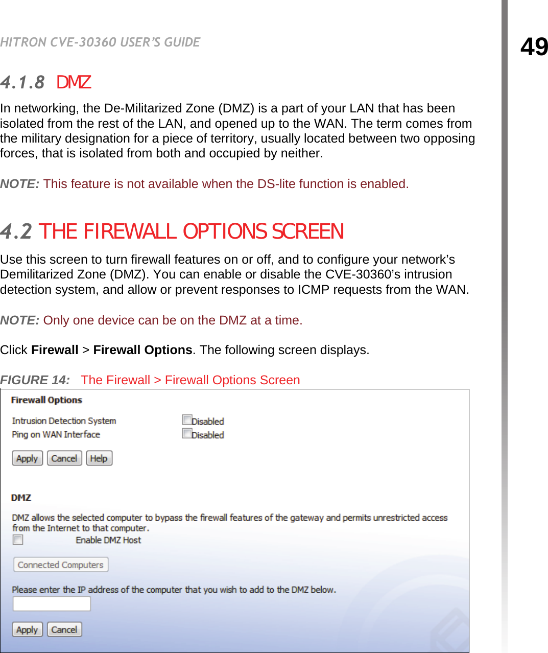
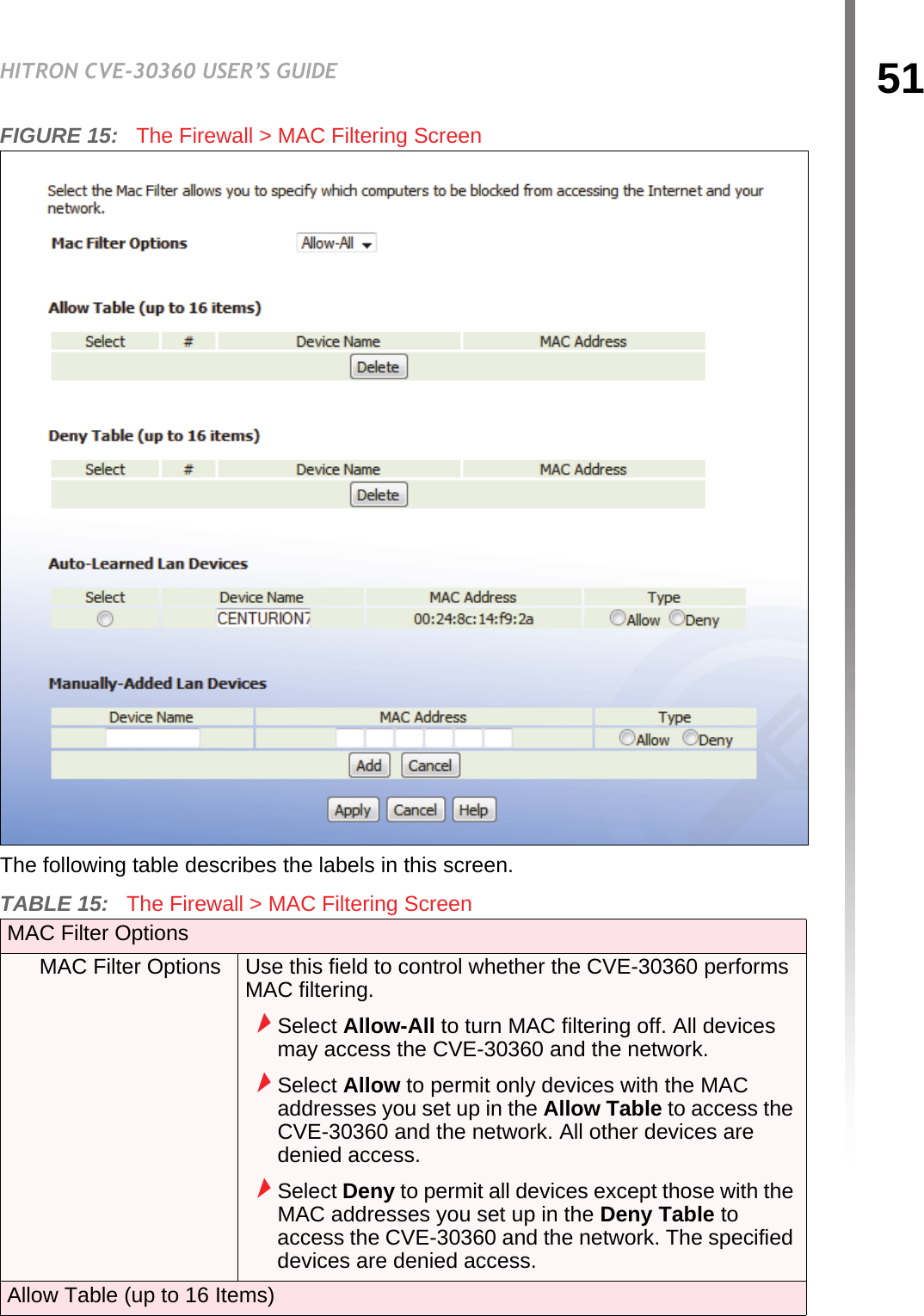
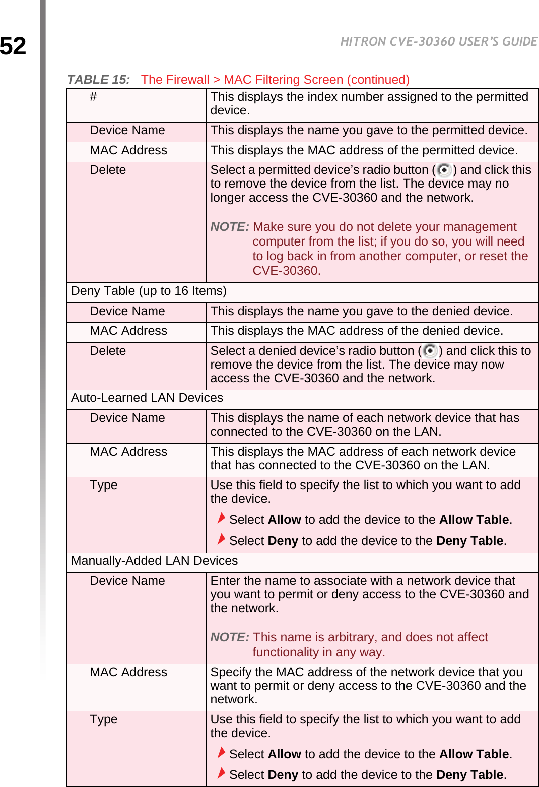
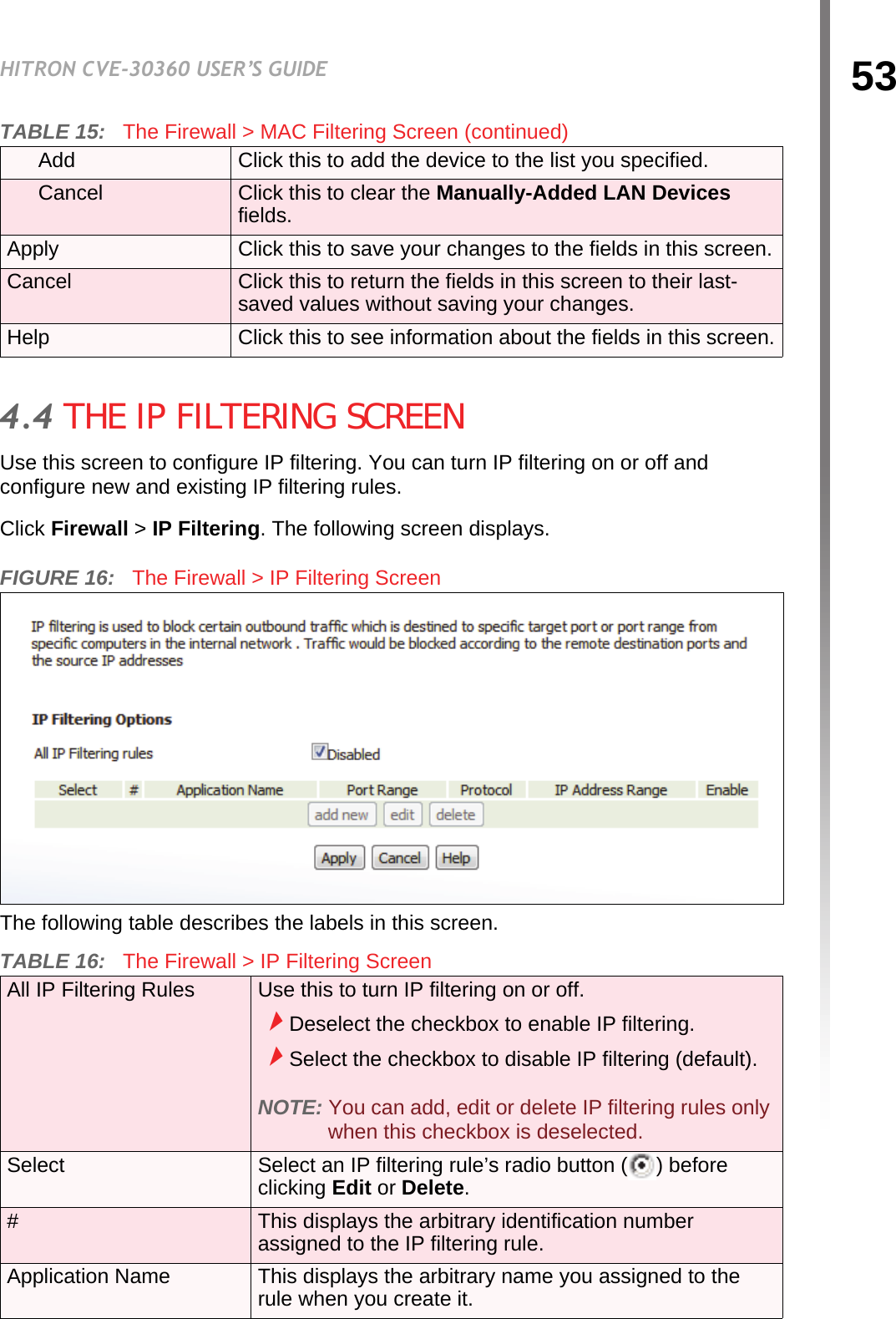
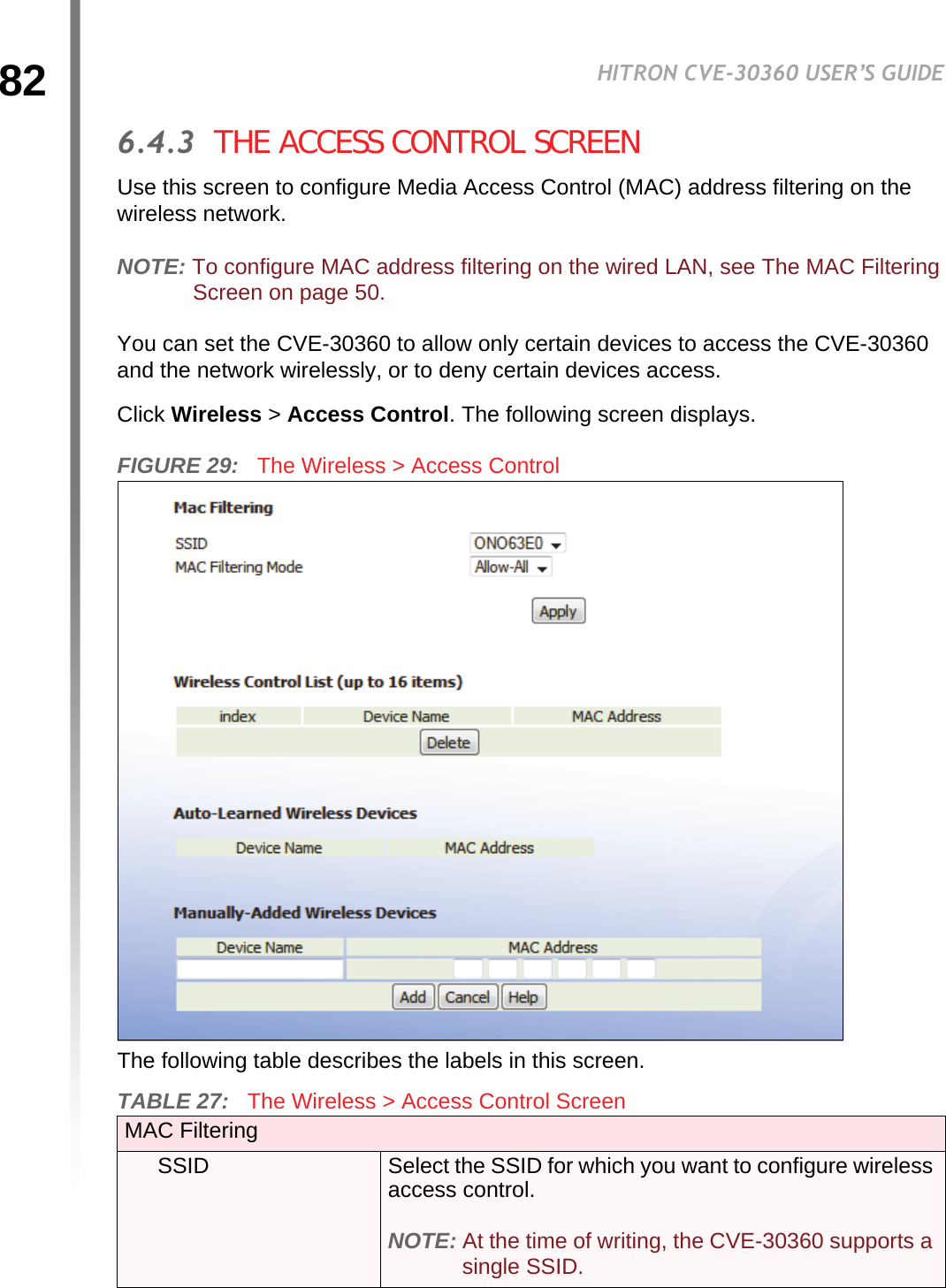
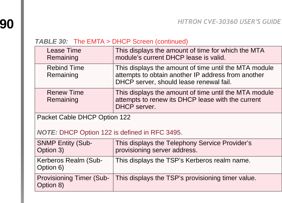
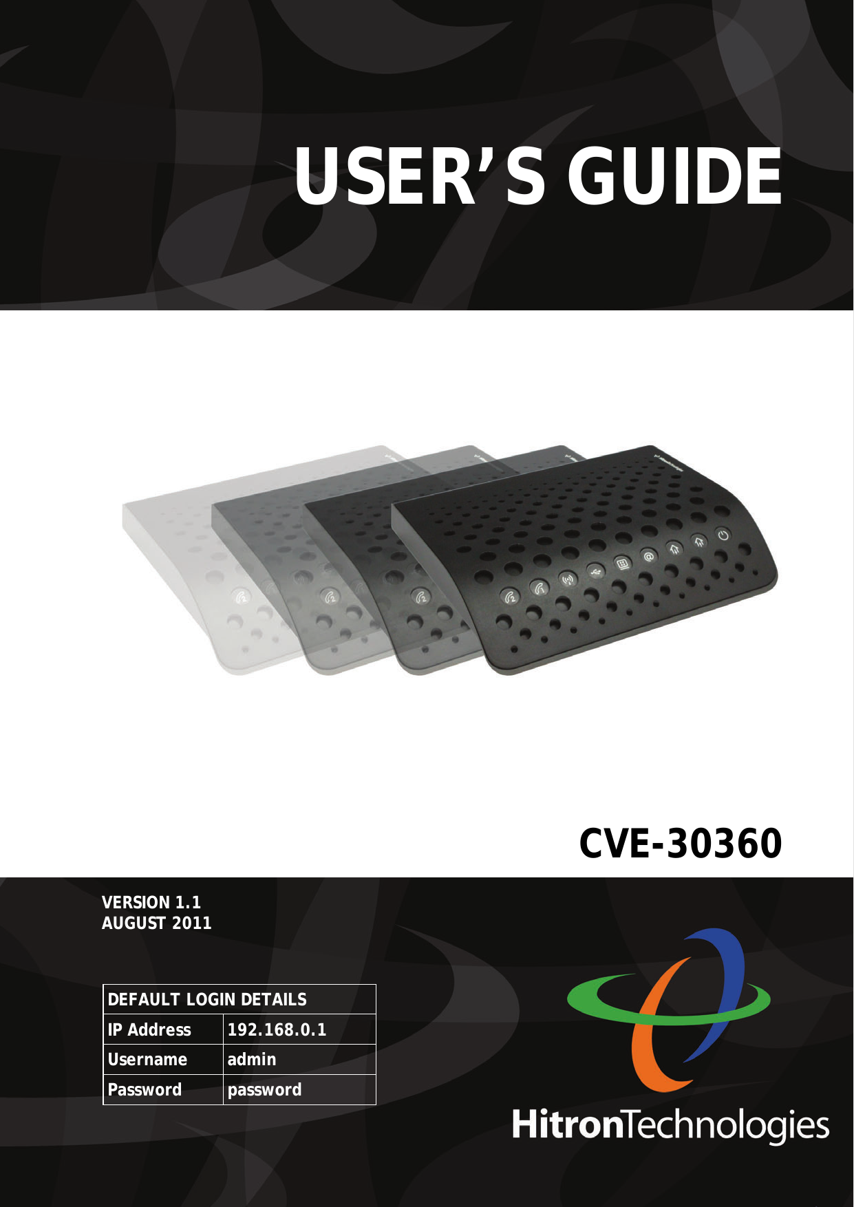
![50HITRON CVE-30360 USER’S GUIDEFIREWALLThe following table describes the labels in this screen.4.3 THE MAC FILTERING SCREENUse this screen to configure Media Access Control (MAC) address filtering on the LAN.NOTE: To configure MAC address filtering on the wireless network, see The Access Control Screen on page 82.You can set the CVE-30360 to allow only certain devices to access the CVE-30360 and the network, or to deny certain devices access.NOTE: To see a list of all the computers connected to the CVE-30360 on the LAN, click the Connected Computers button in the Firewall > IP Filtering, Forwarding, Port Triggering or Firewall Options screens.Click Firewall > MAC Filtering. The following screen displays.TABLE 14: The Firewall > Firewall Options Screen Intrusion Detection SystemSelect this to turn the intrusion detection system off.Deselect this to turn the intrusion detection system on.Ping on WAN InterfaceSelect this to prevent responses to ICMP requests originating from the WAN.Select this to allow responses to ICMP requests originating from the WAN.Enable DMZ Host Use this field to turn the DMZ on or off.Select the checkbox to enable the DMZ.Deselect the checkbox to disable the DMZ. Computers that were previously in the DMZ are now on the LAN.Connected Computers Click this to see a list of the computers currently connected to the CVE-30360 on the LAN.[...] IP Address [...] Enter the IP address of the computer that you want to add to the DMZ.Apply Click this to save your changes to the fields in this screen.Cancel Click this to return the fields in this screen to their last-saved values without saving your changes.Help Click this to see information about the fields in this screen.](https://usermanual.wiki/Hitron-TECHNOLOGIES/CVE1A/User-Guide-1718128-Page-50.png)