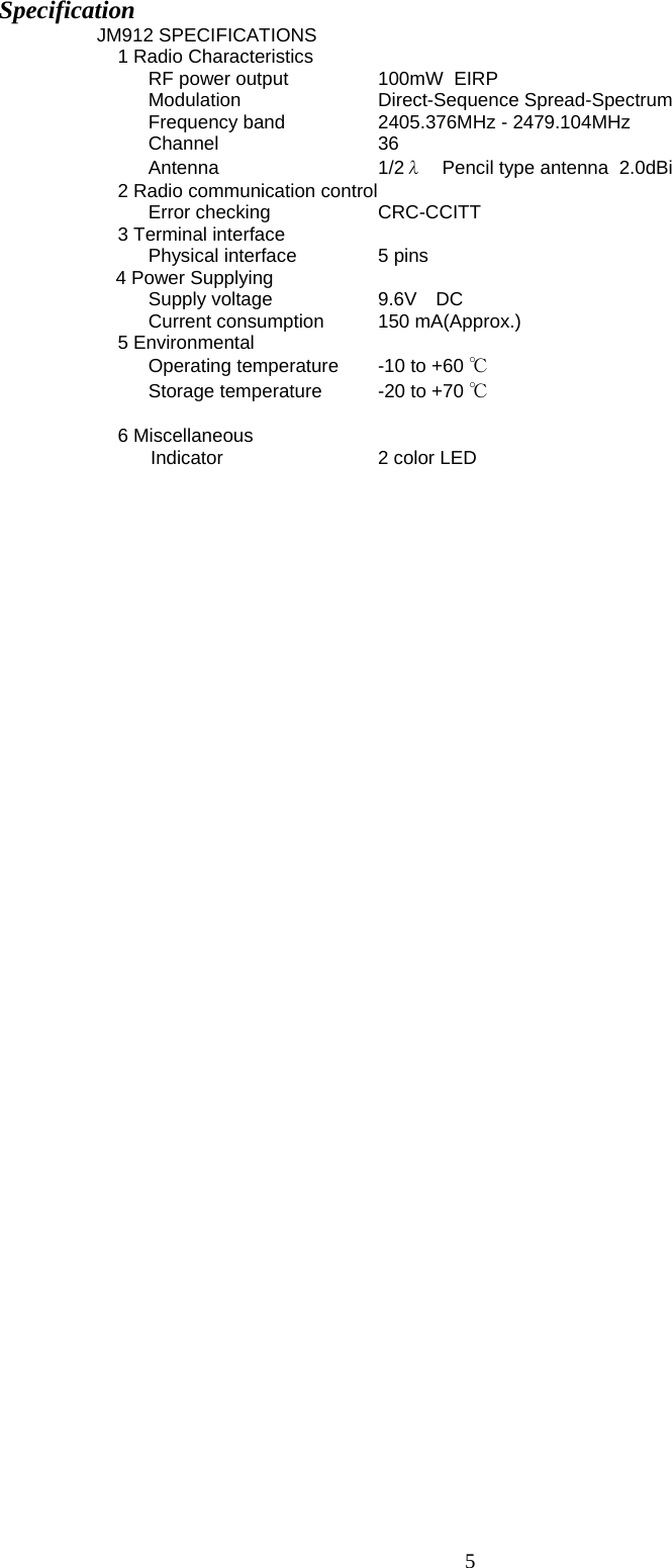
Hobbico TM12J-24G Radio Control (Transmitter) User Manual

Hobbico Inc Radio Control (Transmitter)

User manual

1 Great Planes / Hobbico     JM912 Radio Control  Instruction Manual    INTRODUCTION Thank you for purchasing the JM912 digital proportional R/C system. In order for you to make the best use of your system and to use it safely, please read this manual carefully. If you have any difficulties while using your system, please consult the manual, our online Frequently Asked Questions (on the web pages referenced below), your hobby dealer, or the Hobbico Service Center. Owner’s Manual and Additional Technical Help This manual has been carefully written to be as helpful to you, the new owner, as possible. There are many pages of setup procedures and examples. However, it need not be your sole resource of setup guidelines. For example, the back cover includes a quick-start set of instructions and the Frequently Asked Questions web page referenced below includes this type of step-by-step setup instructions for a variety of other model types. Due to potential unforeseen changes in production procedures, the information contained in this manual is subject to change without notice. No part of this manual may be reproduced in any form, at any time, without prior permission. Support and Service: It is recommended to have your Hobbico equipment serviced annually during your hobby’s “off season” to ensure safe operation.    Please feel free to contact the Hobbico Service Center for assistance in operation, use and programming. Please be sure to regularly visit the Frequently Asked Questions web site referenced below. This page includes extensive programming, use, set up and safety information on your radio system and is updated regularly. Any technical updates and US manual corrections will be available on this web page. If you do not find the answers to your questions there, please see the end of our F.A.Q. area for information on contacting us via email for the most rapid and convenient response.
2 Hobbico Service Center 3002 N. Apollo Drive Suite 1 Champaign, IL 61822 TEL(217)398-8970, FAX(217)398-7721   HOW TO ACCESS to FAQ: To be determined    The product is subject to regulations of the FCC and is restricted under United States law to such purposes. (See end of this manual for detail)
3 Physical Description  JM912  (Transmitter)  PIN ASSIGNMENT  Back side of the JM912Ant.5-pin connector for I/F to transmitter Fig.1 JM912 communication port location  1. Plug the JM912 into your transmitter. 2. Turn the transmitter on and please check the LED on the JM912 become solid green when it’s normally operated. 3. Never point the antenna to the model when flying.
4  Frequency Allocation The JM912 can operate on 36 available frequencies between 2405.376 MHz and 2479.104 MHz with 2.048 MHz separation between each frequency. See the table below for the exact frequency assignments.  Table 1  :Frequency Channel Channel № Frequency (MHz) Channel № Frequency (MHz) 02  2405.376  38  2442.240 04  2407.424  40  2444.288 06  2409.472  42  2446.336 08  2411.520  44  2448.384 10  2413.568  46  2450.432 12  2415.616  48  2452.480 14  2417.664  50  2454.528 16  2419.712  52  2456.576 18  2421.760  54  2458.624 20  2423.808  56  2460.672 22  2425.856  58  2462.720 24  2427.904  60  2464.768 26  2429.952  62  2466.816 28  2432.000  64  2468.864 30  2434.048  66  2470.912 32  2436.096  68  2472.960 34  2438.144  70  2475.008 36  2440.192  72  2477.056     74  2479.104
5 Specification JM912 SPECIFICATIONS 1 Radio Characteristics RF power output     100mW  EIRP  Modulation     Direct-Sequence Spread-Spectrum  Frequency band    2405.376MHz - 2479.104MHz Channel   36 Antenna   1/2λ  Pencil type antenna  2.0dBi  2 Radio communication control Error checking    CRC-CCITT 3 Terminal interface Physical interface   5 pins 4 Power Supplying Supply voltage     9.6V DC Current consumption   150 mA(Approx.)  5 Environmental Operating temperature   -10 to +60 ℃ Storage temperature   -20 to +70 ℃  6 Miscellaneous  Indicator     2 color LED
INSTRUCTIONS MANUAL FEDERAL COMMUNICATIONS COMMISSION INTERFERENCE STATEMENT    This equipment has been tested and found to comply with the limits for a Class B digital device, pursuant to Part 15 of the FCC Rules.    These limits are designed to provide reasonable protection against harmful interference in a residential installation.  This equipment generates, uses, and can radiate radio frequency energy and, if not installed and used according to the instructions, may cause harmful interference to radio communications.    However, there is no guarantee that interference will not occur in a particular installation.    If this equipment does cause harmful interference to radio or television reception, which it found by turning the equipment off and on, the user is encouraged to try to correct the interference by one or more of the following measures:   -- Reorient or relocate the receiving antenna. -- Increase the separation between the equipment and receiver. -- Connect the equipment into an outlet other than the receiver’s -- Consult the dealer or an experienced radio/TV technician for assistance.    CAUTION:   To assure continued FCC compliance:          (1) Any changes or modifications not expressly approved by the grantee of this device could void the user's authority to operate the equipment.  FCC Label Compliance Statement: This device complies with Part 15 of the FCC Rules. Operation is subject to the following two conditions: (1) this device may not cause harmful interference, and (2) this device must accept any interference received, including interference that may cause undesired operation.  Exposure to Radio Frequency RadiationTo comply with FCC RF exposure compliance requirements, a separation distance of atleast 20cm must be maintained between the antenna of this device and all persons.  Thisdevice must not be co-located or operating in conjunction with any other antenna or transmitter.

Navigation menu