Hobbico TTX240A 2.4 GHz Radio Control System User Manual TACJ0245 TTX240 Mnl v2 2 indd
Hobbico Inc 2.4 GHz Radio Control System TACJ0245 TTX240 Mnl v2 2 indd
Hobbico >
Users Manual

Thank you for making the Tactic TTX240 2.4GHz system
your choice for radio control! This system uses modern
2.4GHz Spread Spectrum technology – an innovation that
allows for automatic channel selection and interference-
free control of R/C models.
It is strongly recommended to completely
read this manual before use! Damage
resulting from misuse or modifi cation
will void your warranty.
FEATURES
● 2.4GHz Spread Spectrum Technology
● Transmitter can bind to multiple receivers
● Tiny, lightweight receiver with internal antenna
● Built-in fail-safe
● Steering and throttle trim dials
● Steering and throttle servo reversing
● Steering rate adjustment
● Power LED with low battery warning indication
INSTRUCTION MANUAL
2.4GHz Radio Control System
™
TACJ0245 v2.2
2
TRANSMITTER
The transmitter (Tx) requires 4 “AA”
batteries. Non-rechargeable alkaline or
rechargeable nickel-cadmium (NiCd)
or nickel-metal hydride (NiMH) cells
can be used. Do not mix old and new
cells, or mix non-rechargeable alkaline
cells with rechargeable NiCd or NiMH
cells, etc. See the SERVOS AND
ACCESSORIES section at the end of
this manual for optional rechargeable
NiCd and NiMH batteries and chargers.
Note the TTX240 transmitter does not
include a charge jack for rechargeable
cells. A separate “AA” cell charger will
be necessary.
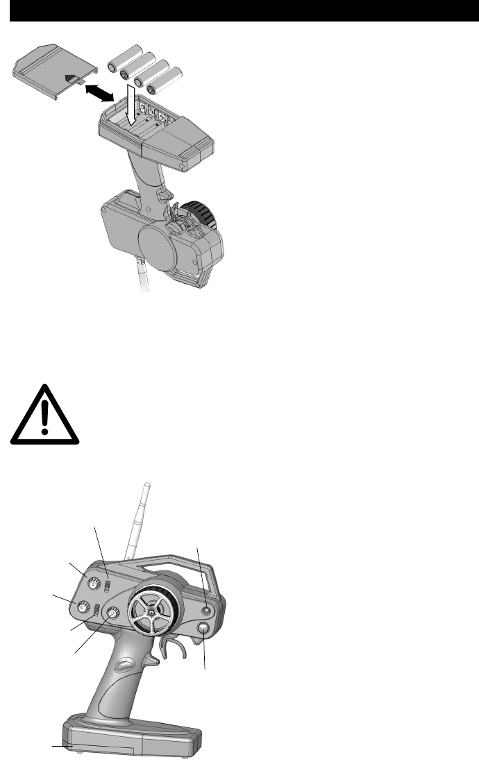
To install the batteries, slide open the battery door on the bottom of the Tx
(see fi gure 1). Install the batteries in the holder as shown in the diagram (see
marks molded inside the case). Make sure to note the proper polarities on
each cell. Close the battery door.
IMPORTANT: Do not operate an R/C model with weak
batteries as it could result in reduced range and/or
possible loss of control!
Press the power switch to turn the Tx
on (see fi gure 2). The “POWER” LED
should illuminate. If not, turn off the Tx
and check the batteries to make sure
each cell is fi rmly in place and in the
proper direction. If the Tx LED blinks,
the batteries are low on power and
should be replaced.
When operating the model, carefully
rotate the Tx antenna so that it’s always
locked in the full upright position.
+
-
+
-
+
-
+
-
4 “AA”
Cells
Figure 1
Antenna
Power
LED
On/Off
Power
Switch
Battery
Cover
Steering
Rate
Throttle
Reversing
Steering
Trim
Steering
Reversing
Throttle
Trim
Figure 2
3
BIND THE RECEIVER TO THE TRANSMITTER
For proper installation and operation of the 2.4GHz transmitter and receiver
system, it is necessary to “bind” them together electronically. This ensures
sole communication between the two and prevents other transmitters from
being able to control the receiver. To bind the Tx and Rx:
1. Turn on the transmitter.
2. Apply power to the receiver (see the INSTALLATION section that follows
for how to do this).
3. If the receiver’s LED fl ashes once and then stays on, the Rx is already
bound to the Tx and you can skip to the next section. Otherwise, push
and hold the receiver’s “BIND” button until its LED glows red and then
turns off after about one second.
4. Release the bind button.
5. If the binding is successful, the LED will fl ash once and then remain ON.
6. Test for proper Tx / Rx functionality by completing the next section. If it
doesn’t seem the radio has bound properly, repeat steps 1-6 above.
INSTALLATION
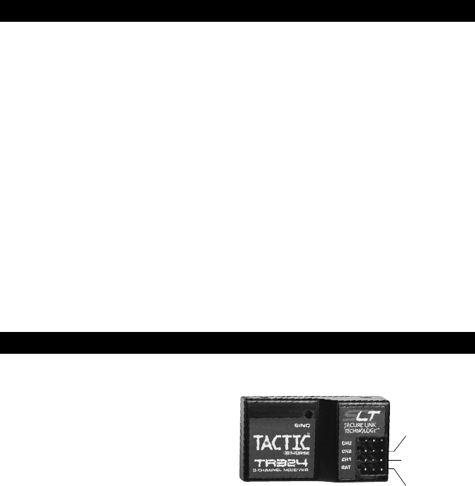
Receiver: Mount the receiver
as specifi ed in your model’s
instructions. As a guideline,
mount in a secure location
using double-sided tape. Route
the servo wires so they do not
interfere with any moving parts.
For boat applications, it’s highly
recommended to wrap the
receiver in a balloon or enclose it
in a water-tight box.
Servos: See the SERVOS AND ACCESSORIES section at the end of this
manual for a full list of optional servos. CENTER THE TRIM DIALS on the Tx.
Mount the servos inside the model and connect the linkages to the servo using
an appropriate length servo arm. Make sure all mechanical linkages are free
of obstructions and can move smoothly. Connect the servos to the receiver as
shown in Figure 3. Turn the transmitter’s trim dials to fi nely adjust the servo’s
center point as needed to match the installation.
Electronic Speed Control (ESC): If using an electronic speed control, connect
it to channel 2 of the receiver (throttle). Center the transmitter’s throttle trim
and follow the ESC instructions for programming.
Figure 3
(2) Throttle
Servo
(1) Steering
Servo
(B) Battery/
Switch
4
Switch / Battery: It may not be necessary to use the included switch harness
and 4-cell battery holder if using an optional electronic speed control (ESC).
Check the instructions with your ESC for further information. Otherwise, mount
the included switch harness into the model as instructed in the model’s manual,
and insert the switch harness’s proper mating plug into the receiver’s “BAT”
slot (bottom). For off-road environments, it’s a good idea to wrap or enclose
the switch harness to prevent dirt from entering the switch and causing poor
operation. Insert four “AA” alkaline, NiCd, or NiMH batteries in the included
4-cell battery holder (note proper polarity). Connect the battery holder to the
switch harness and the switch harness to the BAT slot.
SYSTEM CHECK
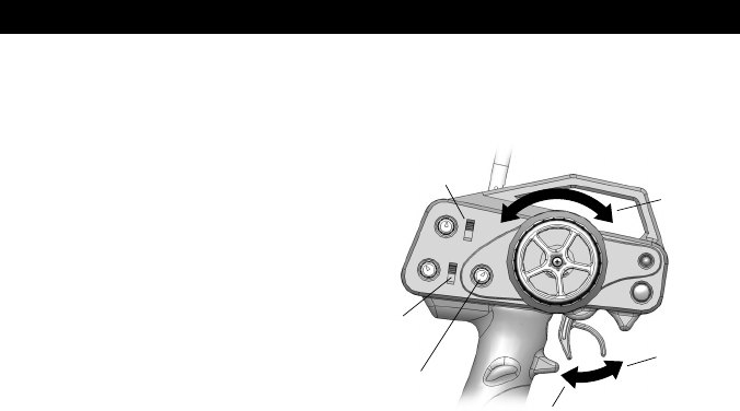
Turn on the Tx, then the Rx. Make sure all servos operate according to the
movement of the Tx controls (refer to fi gure 4).
Steering: Turn the steering
wheel left and right. Make
sure there are no obstructions
with the steering servo’s
movements, and the servo
moves in the proper direction.
If the steering wheel is turned
to the right but the model turns
left, reverse the position of the
Steering Reversing switch.
Steering rate: This dial adjusts
the limits that the steering servo can travel on each side. Turning the dial will
widen or narrow the steering end points. Adjusting this dial to your preference
can help to customize control of steering in different applications.
Throttle: Squeeze the throttle trigger to make the car move forward. If the
car moves backwards, reverse the position of the Throttle Reversing switch.
(See the model’s instruction manual for specifi c set-up instructions.) Push the
trigger forward for reverse or brake function.
Fail-safe: This radio system includes a “fail-safe” function, which will
automatically center (bring to neutral) all servos if the receiver loses signal
communications from the transmitter. When the receiver regains signal it will
automatically resume normal function.
Range check: The “range” or safe operating distance from the Tx to the Rx is
typically as far as you can clearly see the model. Before operating the model,
perform a simple range check to make sure the transmitter maintains good
radio contact with the receiver within your operating area.
Steering
(L & R)
Steering
Rate
Reverse
or Brake
Forward Throttle
Throttle
Reversing
Steering
Reversing
Figure 4

5
SERVOS AND ACCESSORIES
Stock #
TACL0324
TACM2000
TACM2001
TACM2020
TACM2040
DTXM1055
DTXM1059
DTXM1300
DTXM1350
HCAM0120
HCAM0149
HCAM0165
HCAM0191
HCAM0300
HCAM0304
HCAM0308
HCAM0312
HCAM0316
DTXP4190
DTXP4200
DTXP4210
DTXP4615
SANP1100
Description
Tactic TR324 2.4GHz 3CH Receiver Only
Tactic Switch Harness, Futaba J Plugs
Tactic Switch Harness with Charge Plug, Futaba J Plugs
Tactic 4-Cell AA Battery Holder, Futaba J
Tactic TTX240 Tx Battery Door
IntelliSpeed™ AutoSport™ Fwd ESC
IntelliSpeed AutoSport Fwd/Rev ESC
DE10™ Brushless Programmable ESC
Brushless ESC Digital Programmer
CS-35 High Power Mini Servo w/BB
CS-60 Standard Sport Servo
CS-64 High Torque Standard Size 2BB Servo
CS-70MG Super Torque Standard Size 2BB Servo
CS126 Std Size Digital 2BB Servo
CS140 Std Size Digital High Speed 2BB MG Servo
CS150 Std Size Digital High Torque 2BB MG Servo
CS160 Std Size Digital High Torque/Speed MG Servo
CS170 Std Size Digital Ultra Torque 2BB Titanium Gear Servo
ONYX™ 100 AC/DC Peak Charger
ONYX 200 AC/DC Sport Peak Charger
ONYX 210 AC/DC Peak Charger with LCD
Power Kit w/1500mAh NiMH, AC Wall Charger, 8 “AA” alkalines
N-700AAC NiCd 1.2V 700mA Rechargeable “AA” cells
TTX240 SPECIFICATIONS
TRANSMITTER
Channels: 2
Frequencies: 2.403 – 2.480GHz
Modulation: spread spectrum FHSS
Input power: four “AA” alkaline, NiCd, or NiMH cells
Output power: < 0.1W
Power on indicator: red LED
Antenna: non-removable, folding
RECEIVER
Channels: 2
Receiving freqs: 2.403 – 2.480GHz
Modulation: spread spectrum FHSS
Input power: four “AA” alkaline, NiCd or NiMH cells
Dimensions: 1.77 x 0.98 x 0.5” (45 x 25 x 13mm)
Weight: 0.25 oz (7g)

6
TROUBLESHOOTING
RANGE IS SHORT: Interference – check Rx installation and servo connections.
Low Tx or Rx battery – replace the batteries. Crash damage – send the radio
to Hobby Services for repair.
RUN TIME IS SHORT: Low Tx or Rx batteries – replace the batteries. Obstructed
servo linkages causing excess battery drain – free the linkages / pushrods.
Tx LED ON BUT SERVOS DO NOT FUNCTION: Rx batteries are low –
replace the batteries. Rx switch is in the off position – turn on the ESC or
switch harness. Switch harness or ESC is connected incorrectly – check
all connections and the ESC instruction manual. Rx is not binded to the Tx
properly – perform binding process again.
INTERFERENCE OR SERVOS GLITCHING: Out of range – operate the
model more closely to the transmitter. Outside radio interference (pagers, strong
industrial or other commercial transmitters in the area) – check your local R/C
club for confi rmation of dangerous / interfering frequencies in your area.
ONLY ONE SERVO GLITCHES: Servo is bad – replace the servo or send to
Hobby Services for repair.
FCC STATEMENT
This device complies with part 15 of the FCC rules. Operation is subject to the
following two conditions.
(1) This device may not cause harmful interference.
(2) This device must accept any interference received, including interference
that may cause undesired operation.
NOTE: THE MANUFACTURER IS NOT RESPONSIBLE FOR ANY RADIO
OR TV INTERFERENCE CAUSED BY UNAUTHORIZED MODIFICATIONS
TO THIS EQUIPMENT.
Any changes or modifi cations not expressly approved by the party responsible
for compliance could void the user’s authority to operate the equipment.
This equipment complies with FCC radiation exposure limits set forth for an
uncontrolled environment.
This equipment should be installed and operated with a minimum distance of
20cm between the radiator (transmitter) and your body.
This transmitter must not be co-located or operating in conjunction with any
other antenna or transmitter.
7
CE COMPLIANCE INFORMATION FOR THE EUROPEAN UNION
INSTRUCTIONS FOR DISPOSAL OF WASTE EQUIPMENT BY
PRIVATE USERS IN THE EUROPEAN UNION:
This symbol on the product or its packaging indicates this product
must not be disposed of with other household waste. Instead, it
is the user’s responsibility to dispose of their waste equipment by
handing it over to a designated collection point for the recycling
of waste electrical and electronic equipment. The separate collection and
recycling of your waste equipment at the time of disposal will help to conserve
natural resources and ensure that it is recycled in a manner that protects
human health and the environment. For more information about where you
can drop off your waste equipment for recycling, please contact your local
city offi ce, your household waste disposal service or location where you
purchased the product.
DECLARATION OF CONFORMITY:
Product: Tactic TTX240 2.4GHz 2-Channel Pistol Tx Rx
Item number: TACJ0245
Equipment class: 1
EN 60950-1:2006
ETSI EN 300 328 V1.7.1
ETSI EN 301 489-1 V1.8.1,
301 489-17 V1.3.2
Safety
Technical requirements for radio equipment
General EMC requirements for radio equipment
TACTIC TTX240 TRANSMITTER AND TACTIC TR324 RECEIVER:
The objects of the declaration described here are in conformity with the
requirements of the specifications listed below, following the provisions of the
European 2006/95/EC Low Voltage Directive:
The objects of the declaration described here are in conformity with the
requirements of the specifications listed below, following the provisions of the
European R&TTE directive 1995/5/EC:
Tactic
c/o Hobbico, Inc.
2904 Research Road
Champaign, IL USA 61826
CE COMPLIANCE INFORMATION FOR THE EUROPEAN UNION
The associated regulatory agencies of the following countries recognize
the noted certifications for this product as authorized for sale and use.
UK
EE
RO
NL
DE
LV
SI
LU
DK
LT
AT
MT
BG
PL
IT
CY
SE
CZ
ES
GR
FI
SK
PT
HU
IE

© 2011 Hobbico®, Inc. Made in China TACJ0245Mnl v2.2
WARRANTY AND REPAIR (*U.S.A. and CANADA ONLY)
1-YEAR LIMITED WARRANTY
Tactic warrants this product to be free from defects in materials and
workmanship for a period of one (1) year from the date of purchase. During
that period, Tactic will, at its option, repair or replace without service charge
any product deemed defective due to those causes. You will be required to
provide proof of purchase (invoice or receipt). This warranty does not cover
damage caused by abuse, misuse, alteration or accident. If there is damage
stemming from these causes within the stated warranty period, Tactic will,
at its option, repair or replace it for a service charge not greater than 50%
of its then currant retail list price. Be sure to include your daytime telephone
number or e-mail address in case we need to contact you about your repair.
This warranty gives you specifi c rights. You may have other rights, which vary
from state to state.
For service on your Tactic product, send it post paid and insured to:
HOBBY SERVICES Tel: (217) 398-0007
3002 N. Apollo Dr., Suite 1 (9:00am - 5:00pm CST, M-F)
Champaign, IL 61822 E-mail: hobbyservices@hobbico.com
*For warranty and service information if purchased outside the U.S.A. or Canada, ask
your retailer for more information.
tacticrc.com
FCC ID: IYFTTX240A