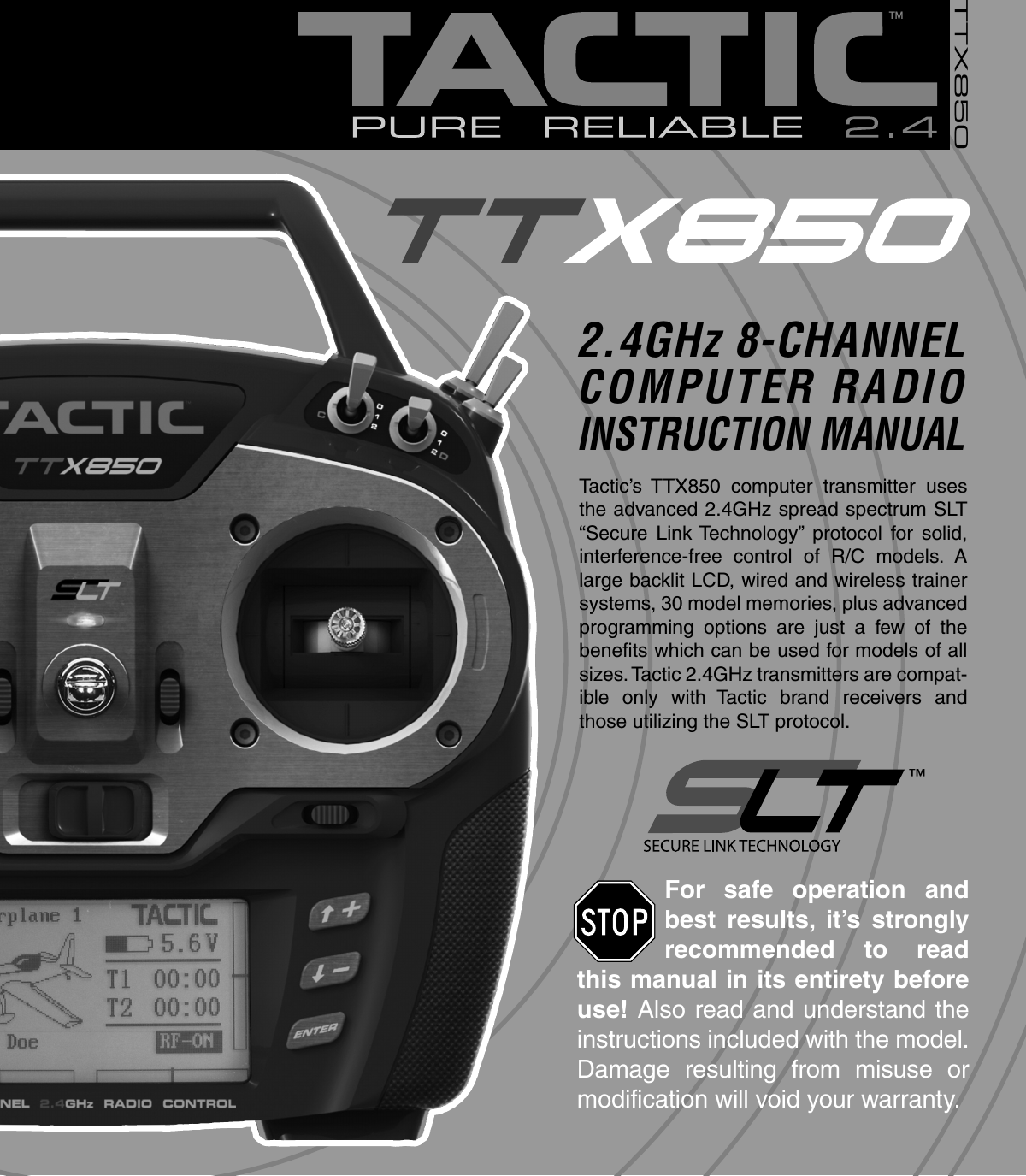
Hobbico TTX850 TTX850 8-Channel 2.4GHz Transmitter User Manual TACJ2850 TTX850 FCC Manual indd
Hobbico Inc TTX850 8-Channel 2.4GHz Transmitter TACJ2850 TTX850 FCC Manual indd
UserManual.wiki
>
Hobbico
>
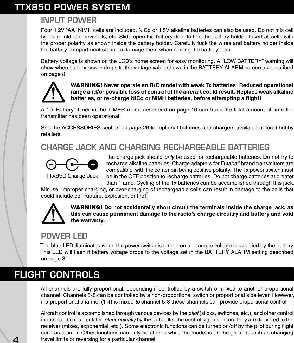
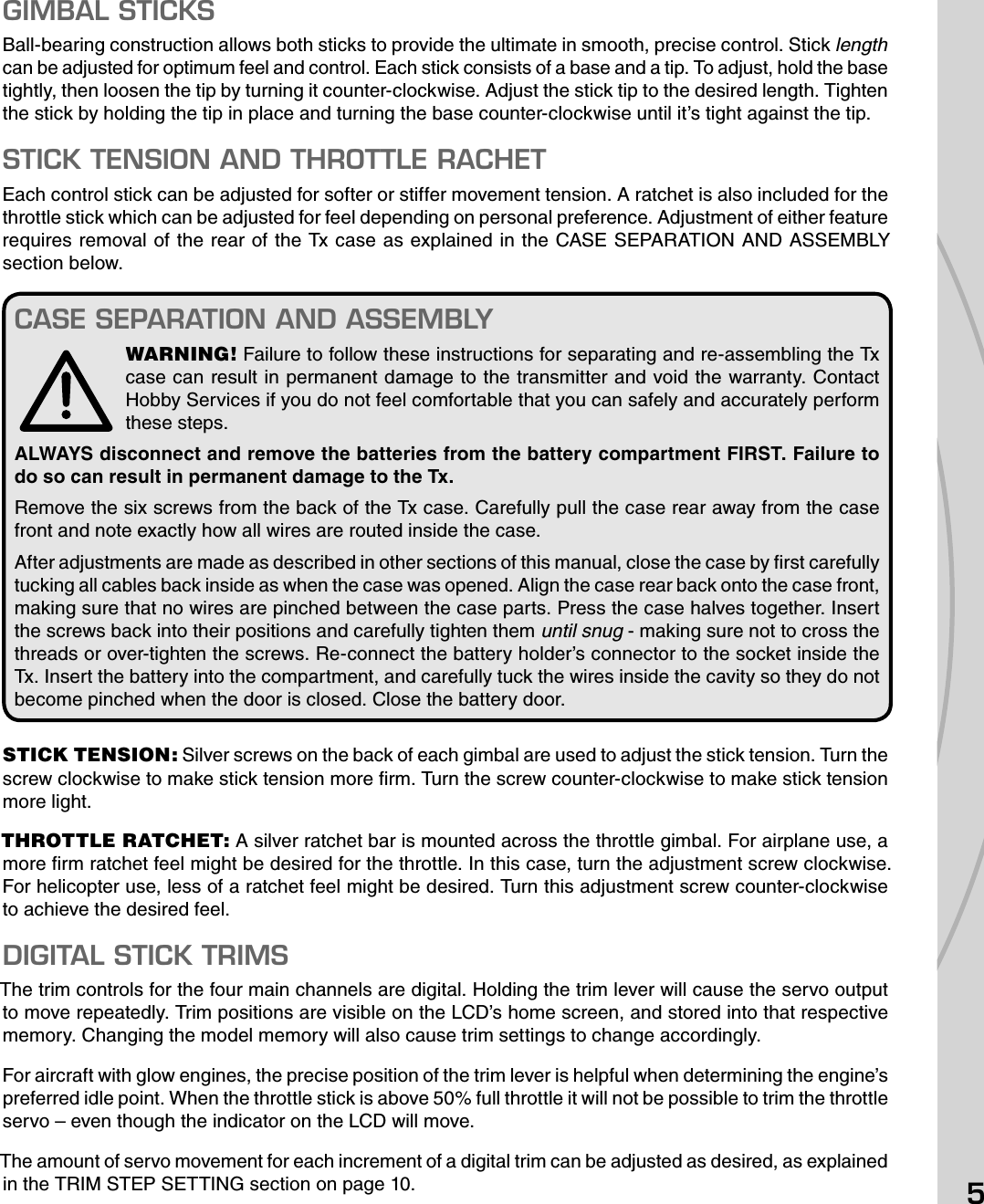
TTX850 User Manual
Users Manual
Navigation menu
Upload a User Manual
Namespaces
Wiki Guide
HTML
PDF
Info
Views
User Manual
Discussion / Help
Navigation