Holder C Trac 4 74 Users Manual Wa
!! Holder-1 Holder Lawn Mower Manuals - Lawn Mower Manuals – The Best Lawn Mower Manuals Collection
4.74 to the manual 60f1dc31-5d6c-4293-b5fc-56a1632daaf2
2015-02-09
: Holder Holder-C-Trac-4-74-Users-Manual-565338 holder-c-trac-4-74-users-manual-565338 holder pdf
Open the PDF directly: View PDF ![]() .
.
Page Count: 211 [warning: Documents this large are best viewed by clicking the View PDF Link!]
- Alphabetical index
- A
- Accessories
- Additional information on implements
- Adjust the driver's seat with mechanical suspension
- Adjust the steering wheel
- Adjusting the backrest inclination
- Adjusting the driver's seat with pneumatic suspension
- Adjusting the driver's weight
- Adjusting the fine control knob
- Adjusting the horizontal suspension
- Adjusting the hysteresis
- Adjusting the length of the pintle hook bar
- Adjusting the lumbar padding
- Adjusting the pintle hooks and pintle hook bars
- Adjusting the seat horizontally
- Adjusting the speedometer
- Adjusting the track width
- Adjusting the upper link
- Air conditioning
- Annual maintenance
- Applying the parking brake
- Applying the service brake
- Attaching implements
- B
- C
- Change hydraulic oil for traction and working hydraulics
- Change the brake fluid of the foot brake
- Change the engine oil
- Change the engine oil filter
- Change the fuel filter and fuel prefilter
- Change the toothed belt
- Changing the direction of travel
- Check / clean the suction filter for working hydraulic system
- Check and clean the cooler and debris screens
- Check engine valve clearances
- Check hose couplings for leaks
- Check the air cleaner system
- Check the battery
- Check the battery and cable terminals
- Check the brake fluid level
- Check the brake fluid level for the foot brake
- Check the brakes and steering for proper operation
- Check the braking system
- Check the cooling system
- Check the electrical system
- Check the engine for leaks
- Check the heating system
- Check the high pressure hoses
- Check the hydraulic oil level
- Check the injection nozzles
- Check the lights and rear view mirror
- Check the steering cylinder and orbitrol
- Check the tire inflation pressure
- Check the trailer hitch (option) if required
- Check V-belt tension and condition
- Clean / replace the fuel pump strainer
- Clean the cooling system
- Clean the fresh air filter
- Clean with cold cleaner or pressure washer
- Clean with compressed air
- Cleaning the condenser
- Connecting equipment to the power socket
- Connecting hydraulic lines
- Controls in cabin at front bottom
- Controls in cabin at front top
- Controls in cabin at rear
- D
- Daily checks and services prior to taking into operation
- Date of issue and manual version
- Description
- Development
- Dimensional drawing
- Disengaging the differential lock
- Door controls
- Driver's licence
- Driver's licence classes
- Driver's station
- Driving
- Driving on slopes
- Driving on-road with implement cushioning
- Driving with hydrostatic drive and digital electronics
- Driving with SDS (Special Drive System)
- Driving with trailers
- E
- F
- G
- H
- I
- J
- L
- M
- Maintenance after the first 50 hours
- Maintenance as required
- Maintenance data
- Maintenance during the first period of operation
- Maintenance every 1000 hours
- Maintenance every 125 hours
- Maintenance every 1500 hours
- Maintenance every 3000 hours
- Maintenance every 500 hours
- Maintenance schedule
- Mounting instructions for licence plates
- Multifunctional display, legend
- Multiple-axle trailers or two-axle trailers with an axle base over 1 metre
- N
- O
- Oil preheating
- Opening the roof hatch
- Operating controls
- Operating instructions
- Operating priority flow valve I
- Operating priority flow valve II
- Operating the air conditioning
- Operating the blue hydraulic couplings
- Operating the driver's cab
- Operating the front power lift
- Operating the front power lift with keyboard
- Operating the green hydraulic couplings
- Operating the hazard warning flasher system
- Operating the horn
- Operating the hydraulic couplings
- Operating the hydraulic cushioning (front power lift)
- Operating the hydraulic dumper
- Operating the implements
- Operating the inching pedal
- Operating the joystick
- Operating the radio
- Operating the rear power lift
- Operating the roof hatch
- Operating the sideshift with the keyboard
- Operating the tilting device with the keyboard
- Operating the trailer hitch automatically, attaching trailers
- Operating the trailer hitch manually, attaching trailers
- Operating the variable pump for implements (setting from-0-100 litres)
- Operating the yellow and white hydraulic couplings
- Operation
- Operation in winter
- Operation with implement cushioning
- Other activities
- Overview of options and variants (selection)
- P
- Pedals
- Periodic maintenance
- Possible implements
- Power socket
- Problems in electronic and hydraulic driving systems
- Problems in engine and exhaust gas turbocharger
- Problems in the hydraulic system and steering
- Problems in the working hydraulic system
- Putting on snow chains
- Putting the vehicle back in service after lay-up
- Q
- R
- Radio and loudspeakers
- Rear console controls
- Rear implement or front/rear combinations
- Rear right view
- Recommended engine oils and greases
- Recommended engine oils and lubricants, continued
- Recommended hydraulic and gear oils
- Releasing the parking brake
- Removal of hydraulic oil for stationary operation
- Remove engine preservation
- Removing implements
- Removing the roof hatch
- Residual hazards and risks
- Right front controls console
- Right rear console controls
- Routine maintenance
- S
- Safety
- Safety instructions for handling implements
- Safety notes for later installations
- Safety notes for maintenance
- Safety precautions for handling fuels and oils
- Securing the dump body (loading platform)
- Selecting on-road travel (transport speed)
- Service
- Setting the working speed of programs 3 and 4
- Shutdown
- Sideshifting the front power lift
- Signalling to the left, signalling to the right
- Single-axle trailers or two-axle trailers with axle base of up to 1 metre maximum
- Site of operation
- Special operating instructions
- Start the engine
- Starting the engine
- Stationary operation
- Steering
- Steering wheel adjustment
- Stopping
- Switching the front power lift to double-acting
- T
- Table of dimensions C 4.74
- Table of driving programs
- Table of driving ranges
- Table of noise levels and absorption rating
- Table of trailers
- Taking into operation
- Taking out of operation
- Technical data
- Technical data /filling quantities
- Theoretical driving speeds
- Tighten nuts and bolts
- Tighten wheel nuts
- Tightening torques
- Tilting the cab
- Tilting the front power lift
- Tires
- Toggle button for Float Position Button
- Towing instructions
- Track widths
- Tractors for farming and forestry (also with implements)
- Trailers, towing
- Transport, hoisting, towing
- Transport safety
- Troubleshooting guide
- Turn on the battery isolating switch
- Turning off the implement variable-displacement pump
- Turning off the priority flow valve
- Turning on and operating the lights
- Turning on high beam
- Turning on the flood light
- Turning on the front PTO
- Turning on the heater
- Turning on the interior light
- Turning on the rear PTO
- Turning on the rotating beacon
- Turning on the top headlights
- Turning on the ventilation
- Turning on windshield wiper/washer
- Turning the implement cushioning off
- Two trailers behind tractors for farming and fores
- Two-stage steering
- U
- V
- W
- A
Date of Issue: 18.11.2005
Order No.: 149 443
Operating Instructions
C-Trac 4.74

149 443 1
C 4.74 Operating instructions
Foreword
Congratulations on having bought a product from HOLDER.
You also ensure getting full value from your vehicle, save
yourself trouble and maintain your warranty. The operating
instructions provide you with the required information.
Development
Due to the continuous improvements made in the design
and equipment of our vehicles, deviations between these
operating instructions and your vehicle may be possible.
Despite taking all care possible in the creation of this manual,
we can not fully exclude mistakes. Please note therefore
that the information, illustrations and descriptions contained
herein can not be used for any legal claims.
These operating and maintenance instructions are supplied
with each vehicle. Keep them in a safe place where they are
available for the driver and owner at any time. If it should
get lost, the owner must get a replacement from the manu-
facturer.
The personnel concerned with the operation and mainte-
nance of the vehicles must be made acquainted with the
operating and maintenance instructions. The owner must
ensure that every operator has received, read and under-
stood this manual.
We thank you for reading and observing this manual. In
case you still have any questions, suggestions for improve-
ments or discovered mistakes, please contact our customer
service.
General notes on service
Detach the warranty card, have it filled in by your dealer
and send the signed card to us.
Have the scheduled services carried out at the proper inter-
vals and have it confirmed with the dealer’s stamp and sig-
nature in this manual. Please note that warranty can only
be claimed if the regular services have been carried out as
scheduled.
C 4.74
Operating instructions
2149 443
Foreword
In case of questions regarding your vehicle, please state
the following data:
Machine type .................................................... eg C 4.74
Engine serial number ................................... eg 00953643
Chassis serial number.................................eg 204000101
Date of sale or date of
complaint ................................................... eg 11.05.2005
Service hours ............................................... eg 500 hours
Date of issue and manual version
November 2005
We wish you safe driving and troublefree working with your
HOLDER C-Trac.
Gebrüder Holder GmbH
Max-Holder-Straße 1
72555 Metzingen
Phone 07123 966 - 0
Fax 07123 966 - 228
E-mail: info@holder-gmbh.com
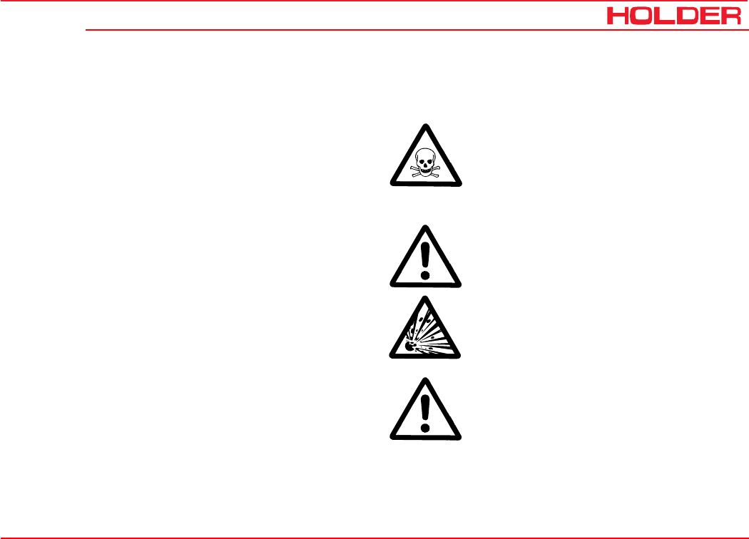
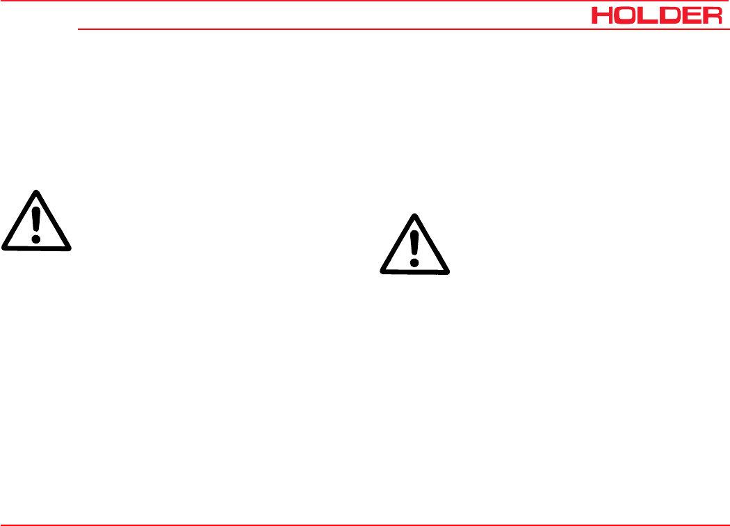
Explanation of terminology:
DANGER
Indicates procedures which must be observed
exactly to prevent danger to the life and limbs
of persons.
CAUTION
Indicates procedures which must be observed
exactly to prevent personal injuries.
ATTENTION
Indicates procedures which must be observed
exactly to prevent damage to and/or destruc-
tion of objects and equipment.
NOTE
Indicates technical requirements needing
particular attention.

Operating instructions
149 443 3
C 4.74 Foreword
Chapter PageChapter Page
Table of contents
Foreword ........................................................................ 1
Instructions for the vehicle ............................................ 5
Operating instructions .................................................... 7
Technical data ..............................................................15
Description ...................................................................28
Taking into operation ....................................................45
Operation ......................................................................59
Special operating instructions .......................................73
Operating the implements .............................................77
Other activities ...........................................................111
Taking out of operation ...............................................125
Trailers, towing ........................................................... 127
Transport, hoisting, towing..........................................131
Indicators, adjustments .............................................. 135
Troubleshooting guide .................................................137
General remarks on maintenance ...............................149
Maintenance schedule ................................................157
Maintenance during the first period of operation ......... 161
Maintenance as required .............................................163
Periodic maintenance ................................................. 167
Maintenance every 125 hours .....................................167
Maintenance every 500 hours .....................................175
Maintenance every 1000 hours ...................................179
Maintenance every 1500 hours ...................................183
Maintenance every 3000 hours ...................................187
Annual maintenance ...................................................189
Laying up .................................................................... 191
Fuel and lubricant recommendations ..........................193
Maintenance data .......................................................197
Alphabetical index ...................................................... 203

149 443 5
C 4.74 Operating instructions
Instructions for the vehicle
This vehicle has received the type approval acc. to 74/150/
EEC after a safety inspection. The vehicle conforms to the
EMC (Electromagnetic Compatibility) requirements of direc-
tive 89/336/EEC. The regulations for exhaust gas identifi-
cation and the noise emissions are observed. The vehicle
must be registered and the licence plate must be attached
at the front and rear.
Intended Use
The vehicle can be used for towing trailers and for mounting
various implements. The maximum trailer load, which must
not be exceeded, is stated on the identification plate. The
transportation of persons is not allowed.
The vehicle is designed solely for the customary type of
operation in farming and forestry, the upkeep of municipal
facilities, including operation in winter.
The intended use also includes the performance of the speci-
fied maintenance. The vehicle and its implements may only
be used, serviced and repaired by persons familiar with this
equipment and have been warned of possible risks. The ap-
plicable safety regulations must be strictly observed, along
with all other recognized rules regarding industrial health,
safety at work and the highway traffic code.
Site of operation
The vehicle must be used in the open. Its operation on pub-
lic roads is allowed. Observe the applicable regulations in
your country for driving your vehicle on public roads.
Unintended applications
Any use not intended as described as above is an unin-
tended use. HOLDER will not be responsible for any hazard
which may result from unauthorized use. The manufacturer
will also not be responsible for any resulting damages; these
shall be solely borne by the user. The vehicle may not be
used for any other purposes than those described in this
manual. Do not carry persons on the load platform or on the
implements.

C 4.74
Operating instructions
6149 443
Instructions for the vehicle
Residual hazards and risks
Despite all care being taken and compliance with standards
and regulations, it is not possible to exclude all risks in the
handling of the vehicle.
The vehicle and all other system components conform to
currently applicable safety regulations. A residual risk can
not be excluded even with approved use of the vehicle and
with observation of all the safety notices given.
For this reason, persons standing in the area the vehicle
and implements must exercise particular caution in order to
be able to react directly in case of malfunction, an incident,
a failure, etc.
CAUTION
All persons standing in the area of the vehi-
cle and implements must be advised of the
risks which can result from their operation.
Furthermore, read and observe the other
safety rules and regulations contained in
these operating instructions.
The risks can include:
- Unexpected movements of the implements and the
vehicle.
- Escape of fuel and lubricants due to leaks, broken
lines and containers, etc.
- Risk of accidents when driving, steering and braking
due to unfavourable ground conditions such as
slopes, icy roads, unevenness or poor visibility, etc.
- Falling, stumbling, etc. when moving on the vehicle,
particularly if it is wet.
- Danger of fires and explosion through the battery and
electric voltages.
- Danger of poisoning through diesel exhaust fumes.
- Danger of fire through diesel fuel and oils.
- Human misconduct through the non-observance of
safety rules.
Notes on disposal of vehicle
Your vehicle is made of different materials. Each material
should be disposed of/treated/recycled according to differ-
ent regional/national regulations. We recommend contact-
ing a salvage company.

149 443 7
C 4.74 Operating instructions
Operating instructions
Driver’s licence
For the driving of this vehicle you require a driver’s licence
depending on the maximum driving speed and the permissi-
ble total weight of the vehicle and combinations. See the
tables below.
Driver’s licence classes
Tractors for farming and forestry (also with implements)
Maximum Speed
(dependent on type) Maximum Total Weight Driver's License Class
(Minimum Requirements)
Former Driver's License
Class (Germany)
up to 32 km/h no limitation B, L, T 1, 1a, 1b, 2, 3, 4, 5
over 32 km/h up to 3.5 tons B
T: 60 km/h,
under 18 years
only 40 km/h
2, 3
over 3.5 tons
to 7.5 tons
C1
T: 60 km/h,
under 18 years
only 40 km/h
2, 3

C 4.74
Operating instructions
8149 443
Operating instructions
Single-axle trailers or two-axle trailers with axle base of up to 1 metre maximum
25
25
25
25
Maximum Total Weight Driver's License Class
(Minimum Requirements)
Former Driver's License
Class
up to 750 kg trailer weight B, C1, C, T
L: only with additional
sign and maximum tractor
speed of 25 km/h
(depending on type)
1, 1a, 1b, 2, 3, 4, 5
over 750 kg trailer weight BE, C1E, CE, T
B, C1, C: only up to
3.5 tons adm. total weight of
the combination and adm.
total weight of trailers
≤ kerb weight of tractor;
otherwise:
C1E: only up to 12 tons adm.
total weight of combination
and adm. total weight of trailer
≤ kerb weight of tractor;
otherwise:
L:
1, 1a, 1b, 2, 3, 4, 5

Operating instructions
149 443 9
C 4.74 Operating instructions
Multiple-axle trailers or two-axle trailers with an axle base over 1 metre
25
25
25
25
25
Maximum Total Weight Driver's License Class
(Minimum Requirements)
Former Driver's License
Class
up to 750 kg trailer weight B, C1, C, T
L: only with additional
sign and maximum tractor
speed of 25 km/h
(depending on type)
2, 3
over 750 kg trailer weight
up to 3.5 tons Maximum Total
Weight
up to 12 tons Maximum Total
Weight
BE, C1E, CE, T
B, C1, C: only up to
3.5 tons adm. total weight of
the combination and adm. total
weight of trailers
≤ kerb weight of tractor;
otherwise:
C1E: only up to 12 tons adm.
total weight of combination
and adm. total weight of trailer
≤ kerb weight of tractor;
otherwise:
L:
2, 3
1, 1a, 1b, 4, 5:
in each case
C 4.74
Operating instructions
10 149 443
Operating instructions
Two trailers behind tractors for farming and forestry
25
25
25
25
Maximum Total Weight Driver's License Class
(Minimum Requirements)
Former Driver's License
Class
up to 3.5 Maximum Total
Weight
up to 12 Maximum Total
Weight
BE, C1E, CE, T
B, C1, C
in each case only up to
3.5 tons adm. total weight of
the combination and adm. total
weight of trailers
≤ kerb weight of tractor;
otherwise:
C1E:
only up to 12 tons adm. total
weight of combination and
adm. total weight of trailer
≤ kerb weight of tractor;
otherwise:
L:
2, 3
1, 1a, 1b, 4, 5,

Operating instructions
149 443 11
C 4.74 Operating instructions
Safety
General notes on safety
• Observe your national regulations on safety and
health protection.
• Do not allow children under 16 to use the vehicle.
• When using the public highway, respect the highway
code.
• Do not allow anyone to stand around where they might
get hurt.
• Do not run the engine in enclosed spaces.
• Exercise extreme caution when handling fuels - there
is a high risk of fire.
• Exercise caution when handling brake fluid and
battery acid (poisonous and corrosive).
• To prevent the danger of fire, keep the vehicle and
implements clean.
• Observe the warning notices and symbols on your
vehicle.
• In case of an emergency stop with a defective
inching pedal or defective traction hydraulics, the
vehicle can only be brought to a halt by turning the
ignition to 0 and applying the service brake.
Work clothing
• Only wear close-fitting clothing when working with the
vehicle.
• If necessary, wear suitable headwear to keep loose
hairs and pigtails from being caught in rotating parts.
• Do not wear any jewellery and similar objects, eg
rings, when working with the vehicle.
Safety notes for later installations
The vehicle has electronic components whose proper func-
tioning can be influenced by electromagnetic emissions from
other equipment. These influences can endanger persons if
the following safety precautions are not observed.
• Have the equipment installed by an authorized work-
shop only.
• Before the installation of electric or electronic equip-
ment connected to the vehicle’s electrical system,
check if these installations can interfere with the
vehicle’s electronic system or other system compo-
nents.

C 4.74
Operating instructions
12 149 443
Operating instructions
• The installed equipment must conform to the applica-
ble EMC directive 89/336/EU and carry the CE
symbol.
• If you must install a mobile communications system
(or have it installed) (eg radio, mobile phone), the
following requirements must be met:
- Only approved equipment (ie with type approval) may
be installed.
- The equipment must be installed firmly.
- The operation of portable or mobile equipment inside
the vehicle is only allowed if connected to a perma-
nently installed external antenna.
- The transmitting section must be installed away from
the vehicle’s electronic system.
- When installing the antenna, install it properly and
with a good connection to vehicle ground.
- Do not exceed the maximum permissible current
rating of the wiring according to the installation in-
structions of the equipment manufacturer.
- When doing electric welding, disconnect all cable
plugs from the electronic units.
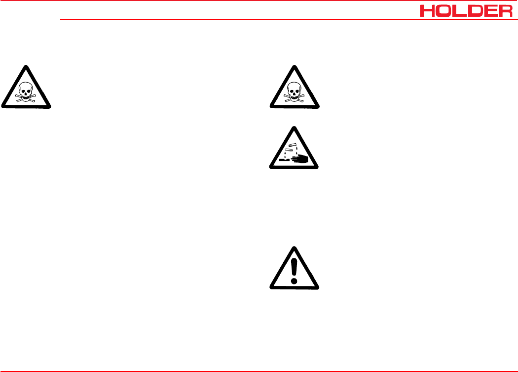
Safety precautions for handling fuels and oils
Gear oil, engine oil, diesel fuel
Do not eat, drink or smoke when handling these
fuels and oils. Prolonged intensive contact may
cause degreasing and irritation of the skin. Wash
skin with water and soap, use skin care prod-
ucts. If required, wear personal protective gear.
Change soaked clothes and shoes immediately.
If vapour or mist was inhaled, breathe fresh air.
Consult a doctor if the complaint persists. After
contact with the eyes, rinse the eyes thoroughly
with water (at least 10 minutes), then consult
an eye doctor. If swallowed, do not force to vomit,
but consult a doctor. Danger of slipping on the
spilled product, particularly in connection with
water.
Oils can contaminate water. Always keep them
in approved containers. Avoid spilling oils. Re-
move spilled fluids immediately with an oil bind-
ing agent and discard in accordance with laws
and regulations. Discard drained fluids as speci-
fied. Observe applicable laws and regulations.
Oils are inflammable. Do not let them come in
contact with hot engine parts as fire can result.
Operating instructions
149 443 13
C 4.74 Operating instructions
Hydraulic oil, brake fluid
During operation, these fluids are pressurized
and pose a health hazard. Do not spill these
fluids. Remove any spilled fluids immediately
with oil binding agent and discard them. Dis-
card drained fluids as specified. Observe appli-
cable laws and regulations. Do not allow them
to come in contact with hot engine parts. Dan-
ger of fire!
Avoid contact with the skin. Avoid the inhala-
tion of spray fog. The penetration of pressu-
rized fluids into the skin is particularly danger-
ous if these fluids are under high pressure and
escape from the hydraulic system through
leaks. Seek medical aid at once in case of such
injuries.
If injuries can not be excluded, use suitable
personal protector (for example, protective
gloves, glasses and skin protection and skin
care creams).
Battery acid
Battery acid contains dissolved sulphuric
acid. This acid is poisonous and caustic. When
working with battery acid, always wear pro-
tective clothing and eye protectors. Do not
allow acid to contact the clothing, skin or eyes;
in case of contact wash immediately with
ample clean water. In case of personal inju-
ries, consult a doctor at once. Neutralize
spilled battery acid immediately.
Discard drained fluids as specified. Observe
applicable laws and regulations.
Emissions
Exhaust gases
During operation, the engine emits exhaust
gas into the environment. The exhaust gas
mainly consists of water vapour, carbon di-
oxide (CO2), carbon monoxide (CO), hydro-
carbon (CH), nitrogen oxide (NOX) and soot.
The components CO, CH and NOX are poi-
sonous or hazardous to health and should
not be inhaled in high concentrations. Soot is
considered to be a carcinogenic material.

C 4.74
Operating instructions
14 149 443
Operating instructions
Particularly the particles contained in the
exhaust gas can cause cancer. For this rea-
son the engine should not be operated in en-
closed spaces.
Heat
The exhaust gases are very hot and can ig-
nite inflammable material. The exhaust gas
pipe should therefore be kept away from ig-
nitable materials.
Battery
During charging, the battery produces a mix-
ture of oxygen and hydrogen (detonating gas).
This mixture of gases is explosive and must
not be ignited. The risk of explosion can be
avoided with the appropriate ventilation and
keeping naked flames away. Observe the
safety rules for handling the battery.
149 443 15
C 4.74 Operating instructions
Technical data
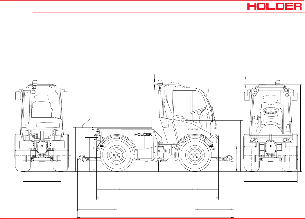
Vehicle dimensions
Dimensional drawing
c
b
h
g
d
605
3090
1065
4140
f
e
517
a
170
100
1075
2005
h

C 4.74
Operating instructions
16 149 443
Technical data
Table of dimensions C 4.74
Trailer hitch
Tires Type Total
height
Avg.
height
Ground
clearance
Lowest
position
Highest
position
Height of
body
Height of
PTO
a
mm
b
mm
c
mm
d
mm
d
mm
g
mm
h
mm
275/80 R18
275/80 R18 S
4131-14
422-31-2 2250 1260 240 850 970 1140 650
36x13.50-15 204-31-03 2245 1260 230 840 960 1130 640
340/65 R18 422-31-06
422-31-07 2245 1260 230 840 960 1130 640
10.5-18 MPT
10.5-18 MPT S
4131-22
422-31-3 2240 1255 230 835 955 1130 640
320/65 R18 422-31-4
422-31-05 2230 1245 215 825 945 1115 625
425/55 R17 204-31-02 2230 1240 215 825 945 1115 625
33x12.50 R15 4131-23 2215 1230 205 810 930 1105 615
33/18LL-16.1 204-31-01 2215 1230 205 810 930 1105 615
33x15.50-15 4131-18 2200 1215 190 795 915 1090 600
31x11.50 R15 203-31-1 2195 1210 180 790 910 1080 590
31x15.50-15 4131-8 2190 1200 175 785 905 1075 585

Operating instructions
149 443 17
C 4.74 Technical data
Track widths
Normal track
1040 mm
Tires Min. turning radius to DIN 7020
(measured at outermost point
of vehicle) Track width e Total width f
Dimension Type m min. mm max. mm min. mm max. mm
422-31-3 6.28 m for track 990 990 1106 1264 1380
275/80 R18 S 422-31-2 6.28 m for track 990 990 1106 1270 1386
320/65 R18 422-31-05 6.31 m for track 990 990 1106 1301 1417
340/65 R18 422-31-07 6.33 m for track 990 990 1106 1313 1429
31x11.50 R15 203-31-1 6.31 m for track 1000 1000 1096 1318 1414
33x12.50 R15 4131-23 6.35 m for track 1006 1006 1090 1349 1433
36x13.50-15 204-31-03 6.40 m for track 1006 1006 1090 1387 1471
10.5-18MPT 4131-22 6.33 m for track 1040 1040 1056 1314 1330
275/80 R18 4131-14 6.33 m for track 1040 1040 1056 1320 1336
320/65 R18 422-31-4 6.36 m for track 1040 1040 1056 1351 1367
340/65 R18 422-31-06 6.38 m for track 1040 1040 1056 1363 1379
425/55 R17 204-31-02 6.52 m for track 1080 - 1080 - 1511
31x15.50-15 4131-8 6.52 m for track 1130 - 1130 - 1524
33x15.50-15 4131-18 6.52 m for track 1130 - 1130 - 1525
33/18LL-16.1 204-31-01 6.65 m for track 1170 - 1170 - 1645

C 4.74
Operating instructions
18 149 443
Technical data
Weights
Weight in kg
Permissible total weight 4000
Permissible load on front axle 2500
Permissible load on rear axle 2500
Permissible supporting load on trailer hitch 600
Auxiliar assemblies Total Front Rear
Rear power lift 81 kg -11 kg 92 kg
Rear PTO gear 60 kg -5 kg 65 kg
Variable-displacement
pump
60 kg 0 kg 60 kg
Loading platform 75 kg 5 kg 70 kg
Tires 31x11.50R15 33x12.50R15 31x15.50-15
33x15.50-15 10.5-18MPT 275/80 R18
340/65 R18 320/65 R18 33/18LL-16.1 36x13.50-15 425/55 R17
Weight of
C-Trac 4.74
(with driver
75 kg)
Tota: kg 2230 2250 2270 2310 2320 2310 2330 2290 2390
Front kg 1240 1250 1260 1280 1285 1280 1290 1270 1320
Rear kg 990 1000 1010 1030 1035 1030 1040 1020 1070

Operating instructions
149 443 19
C 4.74 Technical data
Tires
The pressure can vary depending on the make and use - observe the manufacturer’s information.
Note: Observe the specified tire inflation pressure when carrying the maximum axle loading and when driving on roads.
For maximum drawbar pull off the road and to reduce ground pressure, adapt the inflation pressure to the axle loading
as specified by the tire manufacturer.
Type of tire Load capacity Profile Tube Inflation pressure (in bar) Wheel ballasts
Kerb weight Max.
loading
Type Weight
10.5-18 MPT 10 Cleat profile Yes 2.2 2.2 4134-1 ca. 42 kg
275/80 R18 130B Cleat profile No 1.0 2.0 4134-1 ca. 42 kg
320/65 R18 109A8 Cleat profile No 0.8 1.6 4134-1 ca. 42 kg
340/65 R18 113A8 Cleat profile No 0.6 1.6 4134-1 ca. 42 kg
31x11.50R15 110Q Profile No 1.7 2.8 4134-1 ca. 42 kg
31x15.50-15 8 Profile No 1.1 3.2 4134-2 ca. 43 kg
33x15.50-15 6 Profile No 0.7 1.7 4134-2 ca. 43 kg
33x12.50-R15 * 108Q M + S No 1.7 2.5 4134-2 ca. 43 kg
36x13.50-15 114B Lawn No 1.6 1.6 4134-2 ca. 43 kg
425/55 R17 134G Profile No 1.0 1.6 4134-2 ca. 43 kg
33/18LL-16.1 10 Lawn No 0.6 1.1 - -

C 4.74
Operating instructions
20 149 443
Technical data
Engine specifications
C 4.74
Manufacturer Deutz AG
Type BF4L 2011 Turbo
Mode of operation Four-stroke Diesel
Number of cylinders 4
Cubic capacity 3108
Fuel consumption 229g/KW-h at
1700-1850 rpm
Rated speed 2500 rpm
Maximum idling speed 2500 rpm +350 rpm
Minimum idling speed 900-980 rpm
Rated power acc.
to 97/68 EC
at n = 2500 rpm
54.6 KW (74 HP)

Operating instructions
149 443 21
C 4.74 Technical data
Theoretical driving speeds
30 km/h Model 40 km/h ModelHydrostatic drive
Engine output 54.6 kW
Speed 2500 rpm
Driving range
1
Forward and
reverse
Driving range
2
Forward and
reverse
Driving range
1
Forward and
reverse
Driving range
2
Forward and
reverse
Tires Type
340/65 R18 422-31-06 33.0 16.7 41.2 20.6 km/h
340/65 R18 S 422-31-07 33.0 16.7 41.2 20.6 km/h
275/80 R18 4131-14 33.0 16.6 41.0 20.5 km/h
275/80 R18 S 422-31-2 33.0 16.6 41.0 20.5 km/h
36x13.50-15 204-31-03 33.0 16.5 40.8 20.4 km/h
10.5-18 MPT 4131-22 32.6 16.3 40.3 20.1 km/h
10.5-18 MPT S 422-31-3 32.6 16.3 40.3 20.1 km/h
320/65 R18 422-31-4 32.3 16.2 40.0 20.0 km/h
320/65 R18 S 422-31-05 32.3 16.2 40.0 20.0 km/h
425/55 R17 204-31-02 31.6 15.8 39.0 19.5 km/h
33x12.50 R15 4131-23 30.9 15.4 38.2 19.1 km/h
33/18LL-16.1 204-31-01 30.5 15.2 37.7 18.9 km/h
33x15.50-15 4131-18 30.5 15.2 37.7 18.9 km/h
31x11.50 R15 203-31-1 29.0 14.5 35.9 18.0 km/h
31x15.50-15 4131-8 28.0 14.0 34.7 17.3 km/h

C 4.74
Operating instructions
22 149 443
Technical data
Technical data /filling quantities
Assembly Suppl. information Description
Hydrostatic unit Stepless driving speed, 2 driving ranges
Traction hydraulics
Variable-displacement
pump
Bosch Rexroth AG
- Type Axial-piston variable-displacement pump
- Model Twin pump A4 VG 40 EP1D1 / A4 VG 40 EP1D1
- Displacement 40 cm³/rev, 100 l/min at rated engine speed
- Operating pressure 420 bar
Wheel motor Bosch Rexroth AG
- Type Radial piston motor
- Quantity 4 items
- Model MCR 05
- Displacement In driving range 1 235 cm³/rev with 30 km/h model, 190 cm³/rev with 40 km/h model
In driving ranges
2,3,4
470 cm³/rev with 30 km/h model, 380 cm³/rev with 40 km/h model
- Operating pressure 420 bar
Hydraulic oil tank 42 l (common oil tank for traction and working hydraulics)

Operating instructions
149 443 23
C 4.74 Technical data
Assembly Suppl. information Description
Steering
- Type Hydrostatic with 2 steer cylinders, double-acting
- Steering control valve Orbitrol OSPC 125 LS (1-stage) or OSPD 125/205 (2-stage)
Brakes
- Service brake Knott drum brake, 250x55 hydraulic power assisted
- Operation Hydraulic
- Parking brake Knott drum brake, 250x55 hydraulic power assisted
- Operation Electro-hydraulic accumulator brake
Trailer hitch
- Type Scharmüller, height-adjustable and pivotabler
Front power lift
- Type HOLDER regular 3-point, top link adjustable
- Mounting Category I and II
- Lifting power 2000 kg (measured at pintle hook hitch, at medium position)
- Power lift height approx. 612 mm depending on tires
- No. of cylinders 2 items, double-acting

C 4.74
Operating instructions
24 149 443
Technical data
Assembly Suppl. information Description
Rear power lift
- Type HOLDER regular 3-point, top link adjustable
- Mounting Category I and II
- Lifting power 2000 kg, (measured at tow hook, medium extension length)
- Lift height approx. 720 mm, depending on tires
- Cylinders 2 items, double-acting
Loading platform
- Dimensions LxWxH 1530x1140x300 mm
- Useful load 1400 kg
Working hydraulics (with
steering)
Pump Sauer Sundstrand
- Type SNP 2
- Displacement 17 cm³/rev (42.5 L/min at 2500 rpm engine speed)
- Operating pressure 180-190 bar
Hydraulic oil tank 42 L (common oil tank for traction and working hydraulics)

Operating instructions
149 443 25
C 4.74 Technical data
Assembly Suppl. information Description
PTOs 2 it. (front and rear) sense of rotation: CW when looking on PTO
- Front speed 1000 rpm at 2400 rpm of engine
- Rear speed 540 rpm at 2214 rpm of engine
- Spline profile 1 3/8 “ (6) DIN 9611
PTO clutch Hydraulically-controlled single disc dry clutch
Differential lock Front and rear simultaneously selectable
Electrical system
- Operating voltage 12 V VDC
- Battery 12 V / 100 Ah
- Alternator 12 V / 60 A
- Starter 12 V / 2.3 kW
Fuel system
Fuel tank Diesel fuel 60 L
Vehicle overall
- Operating range -30° to +50°C

Operating instructions
149 443 27
C 4.74 Technical data
Noise level
The vehicle emits the following noise level (measured at
the driver’s ear) according to EC Standard 77/311/EEC;
measurement according to Appendix II).
Table of noise levels and absorption rating
Exhaust gas identification
The absorption rating is stated on the identification plate.
Model Engine
Type Engine Output Noise Level dB(A) Absorption rating
Cabin open* Cabin closed
left right left right
C 4.74 BF4 L 2011 54,6 kW (74 HP) 81 83 79 79 0,8
*Roof vent and side window open
C 4.74
Operating instructions
28 149 443
Description
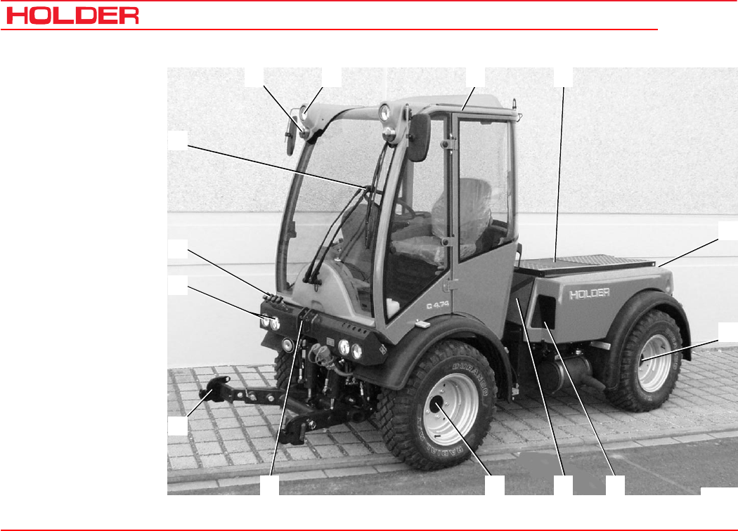
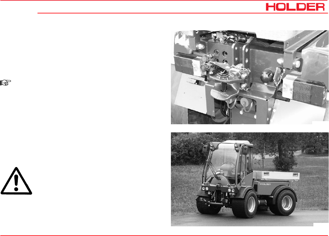
Views
Vehicle
Front left view
1 Turn signal,
position light
2 Headlight, top
3 Driver’s cab
4 Dump body (dumper)
5 Rear of vehicle
6 Rear axle
7 Intake screen for oil
cooler of traction drive
8 Intake screen for
engine
9 Front axle
10 Upper link support
11 Front power lift -
lower link support
12 Headlight
13 Hydraulic quick
couplings for imple-
ment*
14 Windshield wiper/
washer
1234
5
6
78
9
10
11
12
14
13
Bild_C224
149 443 29
C 4.74 Description
Operating instructions
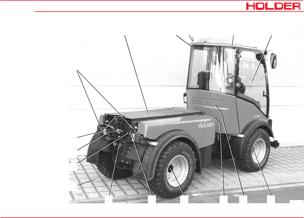
Vehicle
Rear right view
1 Dump body
2 Flood light*
3 Support for
rotating beacon
4 Driver’s cab
5 Front part of vehicle
6 Front axle
7 Intake screen for
fresh air blower
8 Fuel filler neck
9 Rear axle
10 Battery isolating
switch
11 Hydraulic quick
couplings for imple-
ment*
12 Rear power lift*
Lower link support
13 Connector socket for
trailer lighting
14 Trailer hitch
15 Two-port cock for
dump body/rear power
lift
16 Tail light, LH/RH
* Option
2345
6
7
8
9
10
11
12
16
1
15
14
13
Bild_C228
C 4.74
Operating instructions
30 149 443
Description
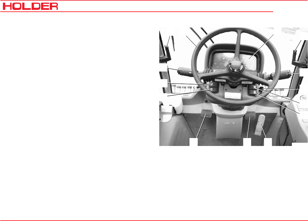
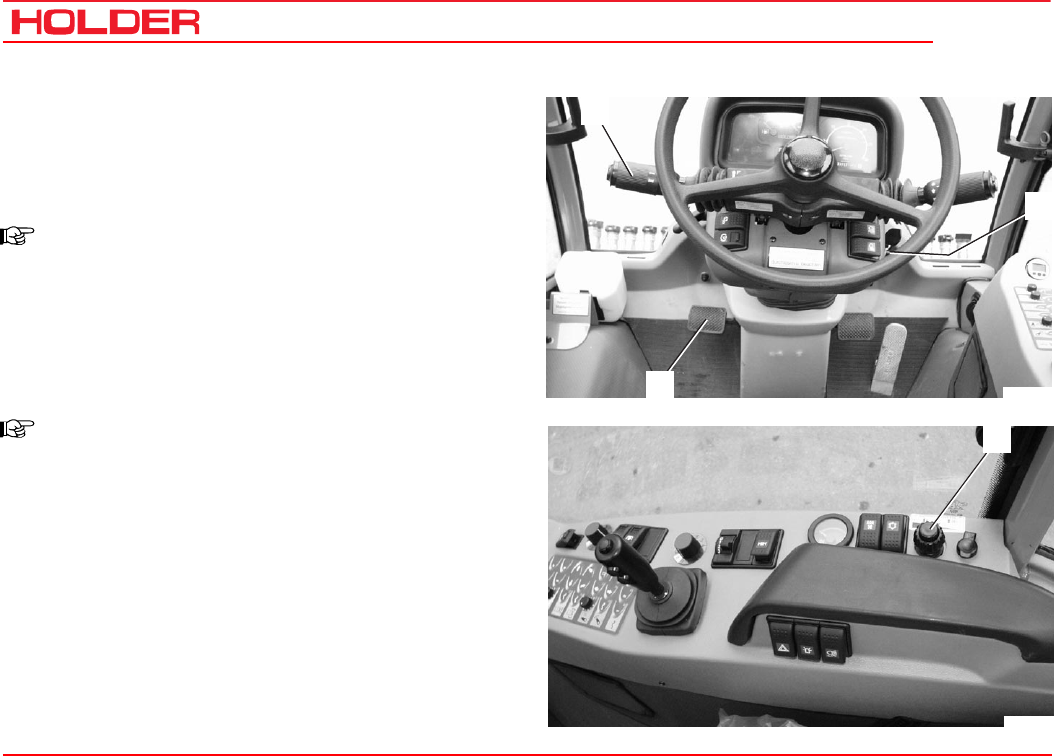
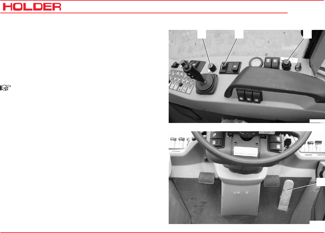
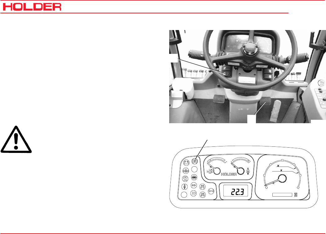
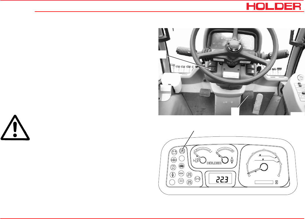
Driver’s station
Operating controls
1 Direction lever
2 Handle for LH side window
3 Steering wheel
4 Multifunctional display
5 Handle for RH side window
6 Turn signal and wiper control lever
7 Ignition lock
8 Light switch
9 Top headlight switch
10 Accelerator pedal
11 Brake pedal
12 Inching pedal
13 Parking brake switch
14 Switch for two-stage steering*
1
2345
9
8
7
6
1011
12
13
14
Bild_C142
* Option

149 443 31
C 4.74 Description
Operating instructions
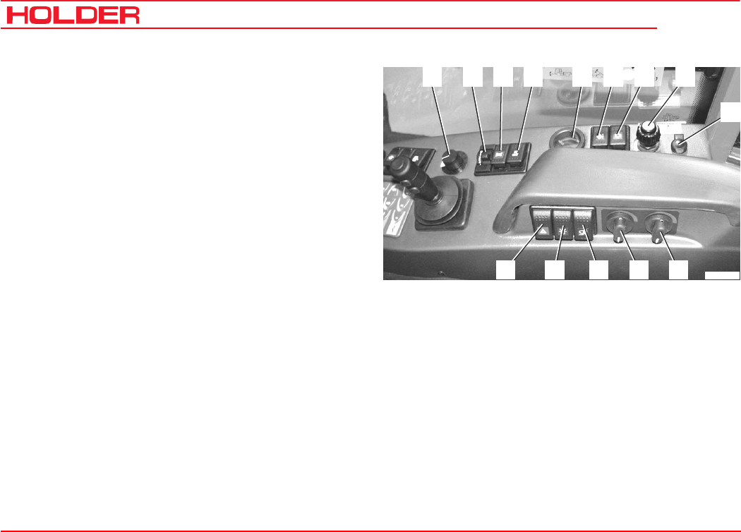
Right front controls console
1 Pressure gauge for hydraulic cushioning*
2 Main switch for implement hydraulics
3 Fine control knob for implement variable-displace-
ment pump*
4 Switch for implement variable-displacement pump*
5 Switch for front PTO*
6 Joystick for working hydraulic system
7 Fine control knob for driving speed (in the driving
speed ranges 3 and 4)
8 Driving program switch
9 Floating positions for 3 quick couplings
10 Keyboard for front power lift
11 Keyboard for tilting
12 Keyboard for sideshifting*
13 Keyboard for flow divider 2nd circuit*
14 Keyboard for flow divider 1st circuit*
4 5 6 7
8
11121314 910
2 31
Bild_C143
* Option
C 4.74
Operating instructions
32 149 443
Description
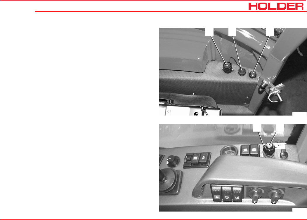
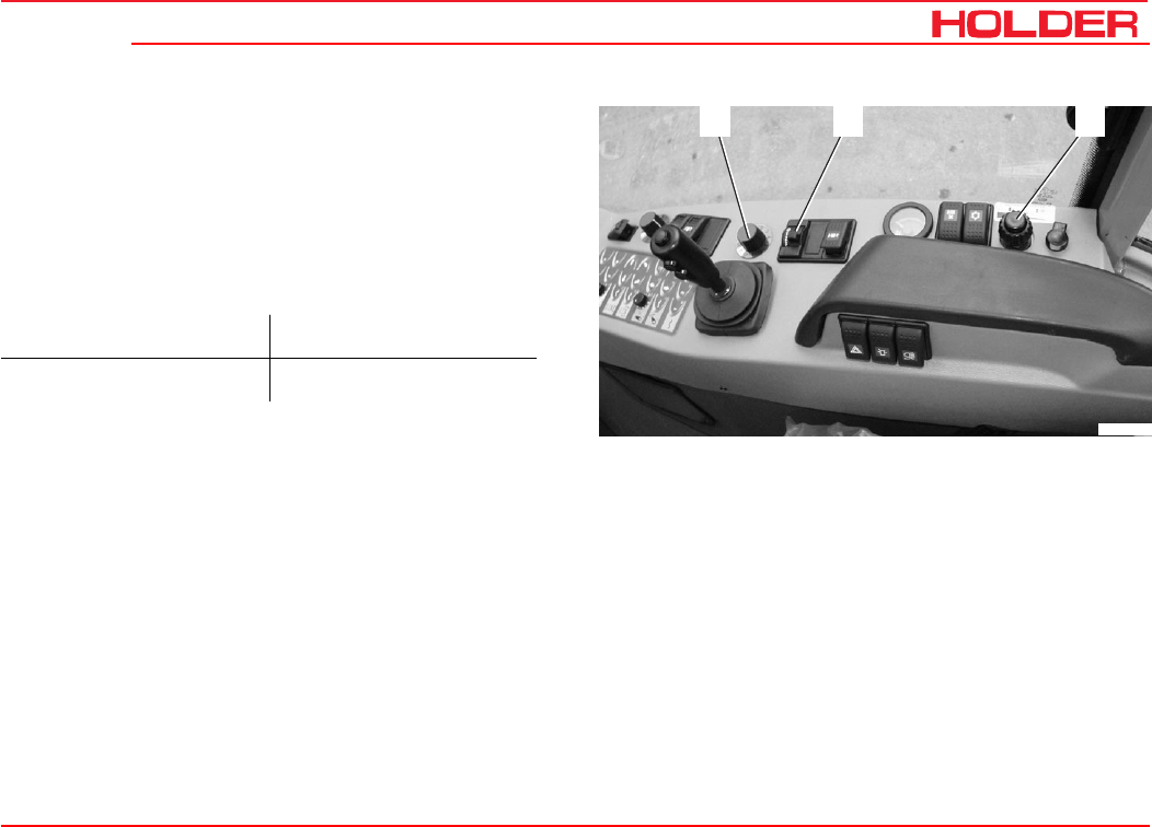
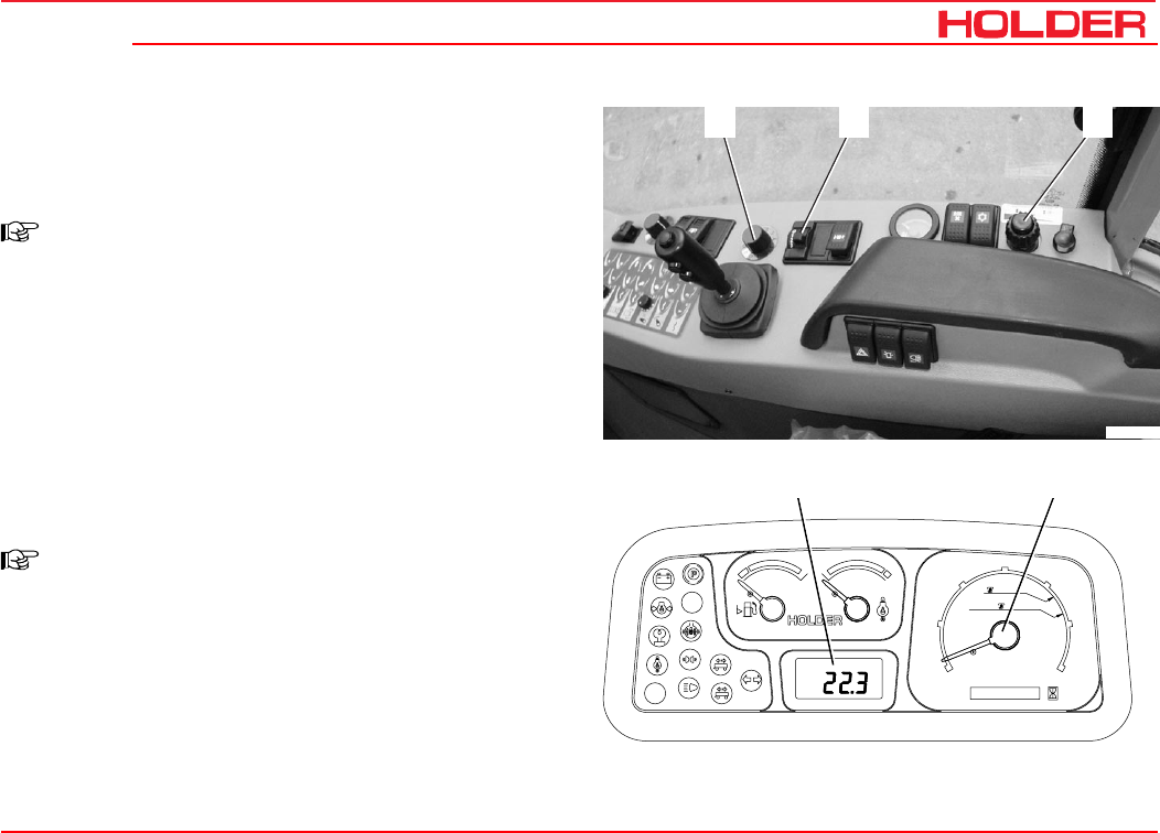
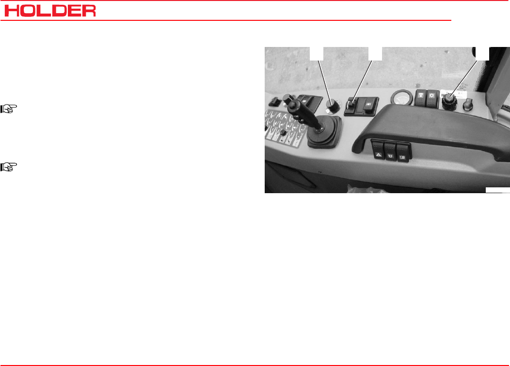
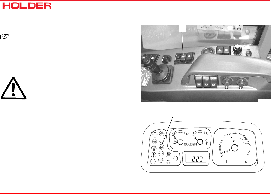
Right rear console controls
1 Fine control knob for driving speed (in the driving
speed ranges 3 and 4)
2 Driving program button
3 Differential lock switch
4 Fan switch
5 Hydraulic oil temperature gauge
6 Fan reversing switch*
7 Air conditioning switch*
8 Hand throttle knob
9 Power socket
10 Heater control
11 Air conditioning control*
12 Flood light switch*
13 Rotating beacon switch
14 Hazard warning switch
54 6 7 8
9
14 1213 1011
31 2
Bild_C274
* Option
149 443 33
C 4.74 Description
Operating instructions
Rear console controls
15 Diagnosis socket for working hydraulics
16 Diagnosis socket for traction hydraulics
17 Traction electronics warning light
1716
15
Bild_C216
1 2
Bild_C275
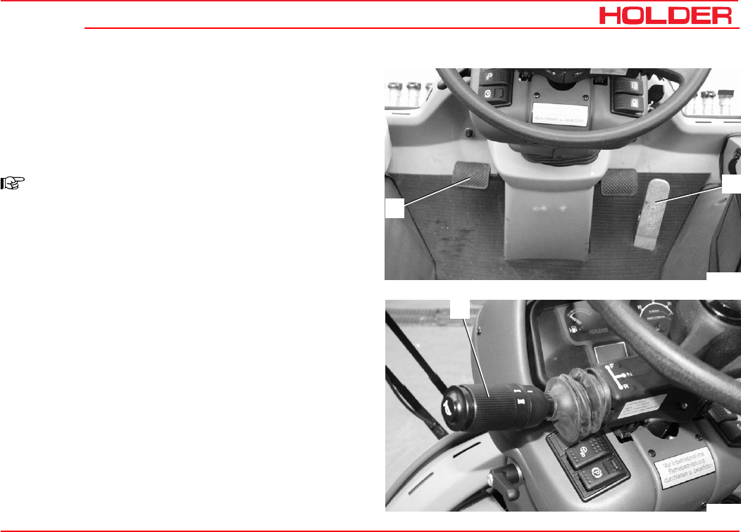
Hand throttle
1 Outer ring for fine control:
- Turn clockwise to decrease rpm
- Turn counter-clockwise to increase rpm
2 Inner knob for coarse adjustment
- Pull out to increase rpm
- Push in to decrease rpm
- Push in fast for emergency reset to idle rpm
C 4.74
Operating instructions
34 149 443
Description
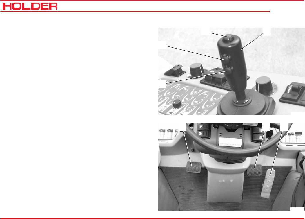
Joystick
1 Pushbutton 1 for joystick level 1
2 Pushbutton 2 for joystick level 2
3 Pushbutton 3 for joystick level 3
4 Joystick (joystick level 0)
4
3
1
2
Bild_C145
2 3
1
Bild_C146
Pedals
1 Inching pedal
2 Brake pedal
3 Accelerator pedal
149 443 35
C 4.74 Description
Operating instructions
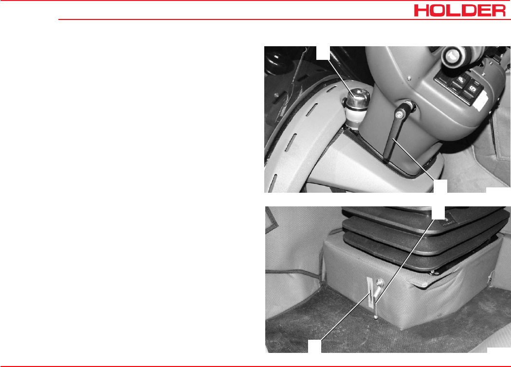
Steering wheel adjustment
1 Brake fluid reservoir
2 Steering wheel adjustment lever
Heater until 04.2005
1 Heater control valve
2 Heating temperature label
- horizontal - cooler
- vertical - warmer
1
2
Bild_C153
1
2
Bild_C147
C 4.74
Operating instructions
36 149 443
Description
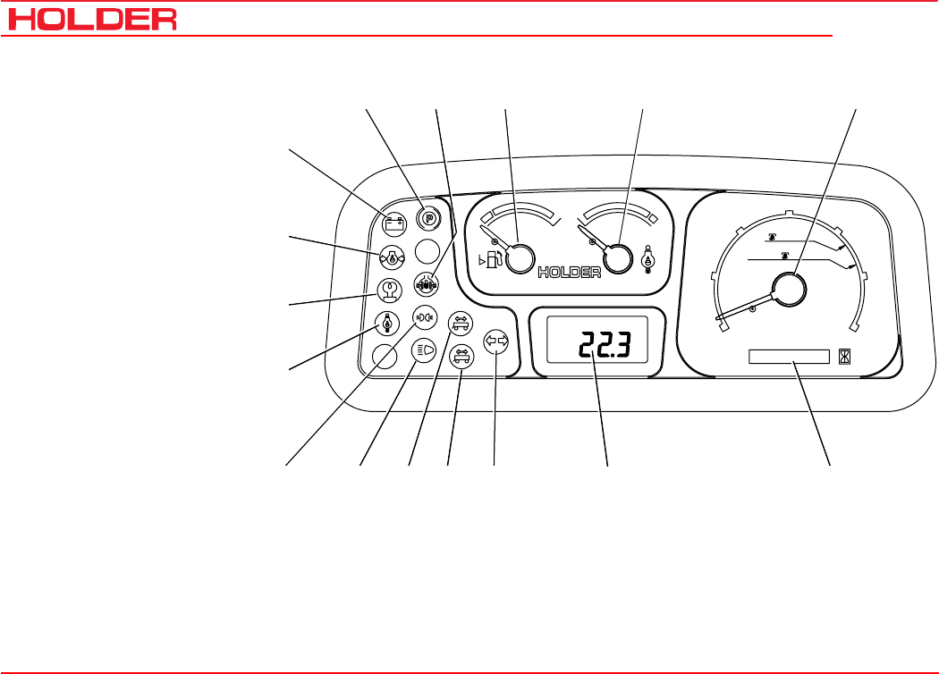
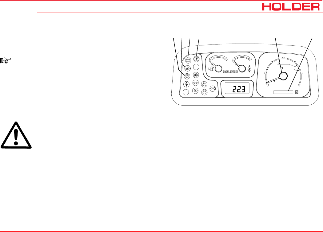
Multifunctional display, legend
1 Fuel gauge
2 Engine oil temperature
gauge
3 Tachometer with mark-
ings for PTO rpm
4 Hour meter
5 Digital speedometer
6 Turn signal indicator
7 Turn signal indicator for
2nd trailer
8 Turn signal indicator for
1st trailer
9 High beam
10 Dip beam
11 Engine oil temperature
12 Preheating indicator
13 Engine oil pressure
warning light
14 Battery charging indicator
15 Parking brake
16 Differential lock
Km/h
0000000 h
25
15
FRONT
540U/min
1000U/min
20
5
10
30
RPMx100
PTO
electronic
0
Motor
digital system
1
2
65478910
11
12
13
14
15 16 1 2 3
Bild_C148
149 443 37
C 4.74 Description
Operating instructions
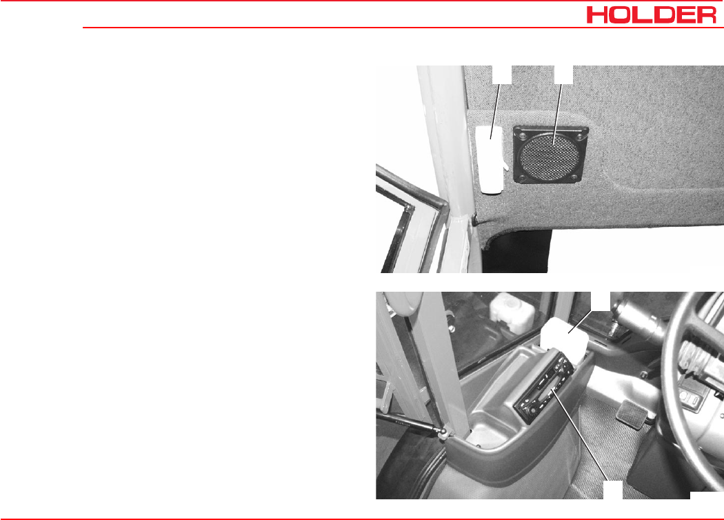
Controls in cabin at front top
1 Interior light
2 Loudspeaker
Controls in cabin at front bottom
1 Washing water reservoir
2 Radio
1 2
Bild_C149
1
2
Bild_C282
C 4.74
Operating instructions
38 149 443
Description
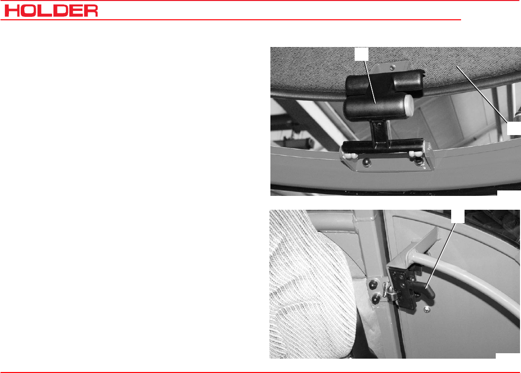
Controls in cabin at rear
1 Roof hatch handle
2 Roof hatch
Door controls
1 Door opener
1
Bild_C156
2
1
Bild_C263
149 443 39
C 4.74 Description
Operating instructions
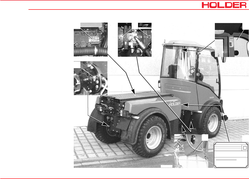
Location of plates and
labels
Identification plates
1 Engine type plate
2 Variable-displacement pump
type plate
3 Cab type plate
4 Machine type plate
(on fuel tank)
5 Chassis number
(On front frame at right
looking forward)
6 Wheel motor type plate
0,8
4000 kg
2500 kg
2500 kg
2200 kg
4500 kg
Technisch zulässige Anhängelast
ungebremste Anhängelast
auflaufgebremste Anhängelast
Zulässiges Gesamtgewicht:
Zulässige Achslast vorn:
Zulässige Achslast hinten:
Identifizierungsnummer : 204000102
Typ : 204
GEBRÜDER HOLDER GMBH
EWG-Nr.: e1 - 74/150-0058
12
54
3
6
Bild_C229
C 4.74
Operating instructions
40 149 443
Description
Mounting instructions for licence plates
- Install the front licence plate (1) on the cover below
the windshield wipers.
First remove the cover before installing the licence
plate.
- Install the rear license plate (2) at the rear below the
left tail light.
2
Bild_C152
1
Bild_C264

149 443 41
C 4.74 Description
Operating instructions
Overview of options and variants (selection)
Assembly Additional information Dimension/Order
No./Type
Hydraulic sideshift 204-01-01
Heating element for preheating oil from –20°C (230 VAC) 204-34-69
Air conditioning 204-34-79
Backrest extension, comfort 204-34-80
Food light, rear 204-34-88
Front power lift 204-51-01
Rear power lift 204-51-02
Trailer hitch, automatic 204-51-70
Trailer hitch, manual 204-51-71
Front PTO 1000 rpm 204-62-01
Front PTO 540 rpm 204-62-02
Rear PTO 540 rpm 204-62-03
Hydraulic cushioning 204-80-19
Rotating beacon 526-34-74

C 4.74
Operating instructions
42 149 443
Description
Assembly Supplementary information Dimension/Order
No./Type
Flow divider, 1st circuit 204-80-04
- Pump Series pump
- Delivery capacity 17 cm³/rev
- Flow rate 0-25 litres/min
- Maximum pressure 200 bar
Flow divider, 2nd circuit 204-80-15
- Pump Tandem pump
- Delivery capacity 14 cm³/rev
- Flow rate 0-25 litres/min
- Maximum pressure 200 bar
Variable-displacement pump 0-100 litres/min adjustable 204-80-30
- Delivery capacity 0-40 cm³/rev
- Maximum pressure 280 bar
149 443 43
C 4.74 Description
Operating instructions
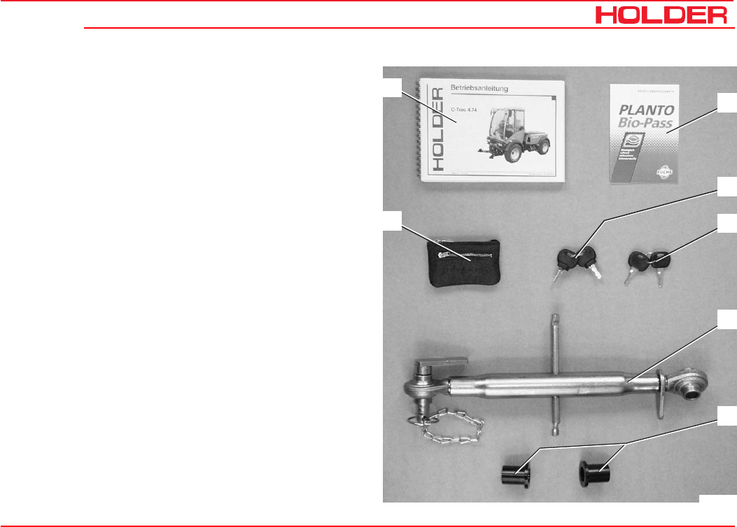
Accessories
The vehicle is delivered with the following accessories:
1 Operating instructions
2 Bio-pass for certification of filling
with environment-friendly hydraulic oil
3 Key holder
4 Two ignition keys
5 Two door keys
6 Upper link with retaining pins
7 Two reducers for category II implements
12
5
4
6
7
3
Bild_C265
149 443 45
C 4.74 Operating instructions
Taking into operation
Daily checks and services prior to taking
into operation
If damage or defects are found during the following checks,
they must be eliminated before taking the vehicle into ser-
vice. Do not operate the vehicle before proper repairs are
carried out. Safety and protective devices should not be
removed or disabled. Fixed specified settings may not be
changed.
Before starting work, make yourself familiar with all the func-
tions and protective devices of the vehicle.
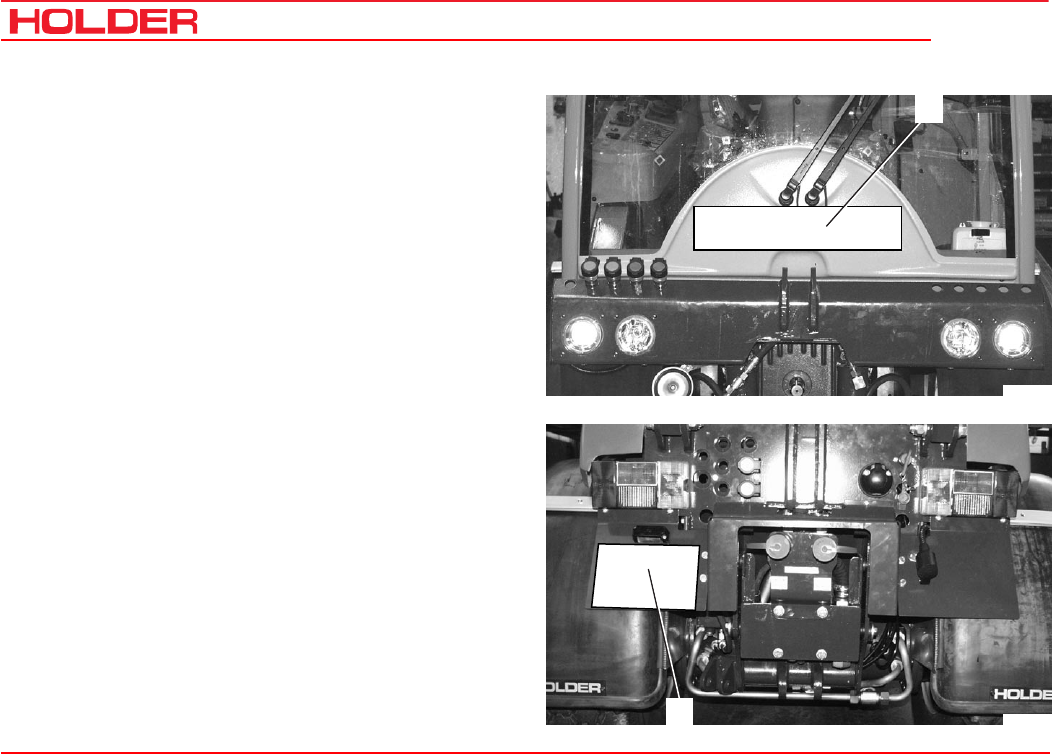
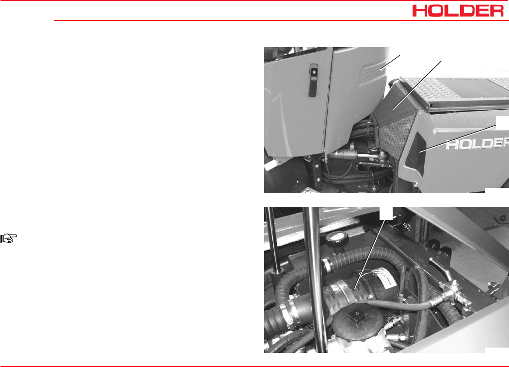
Check and clean the cooler and debris screens
NOTE
- Check if the debris screens (2,3 and 4)
are clean.
- Clean the screens if necessary.
The screen (3) can be pulled out later-
ally to the left after removing the two
screws and then cleaned easily.
- The air intake of the air cleaner (1) must
be clean.
1
Bild_C155
3
4
2
Bild_C154
C 4.74
Operating instructions
46 149 443
Taking into operation
Turn on the battery isolating switch
NOTE
The battery can be switched off completely
with the removable key.
- Insert the key (1) into the battery isolating switch and
turn it to the vertical position.
The battery circuit is turned on.
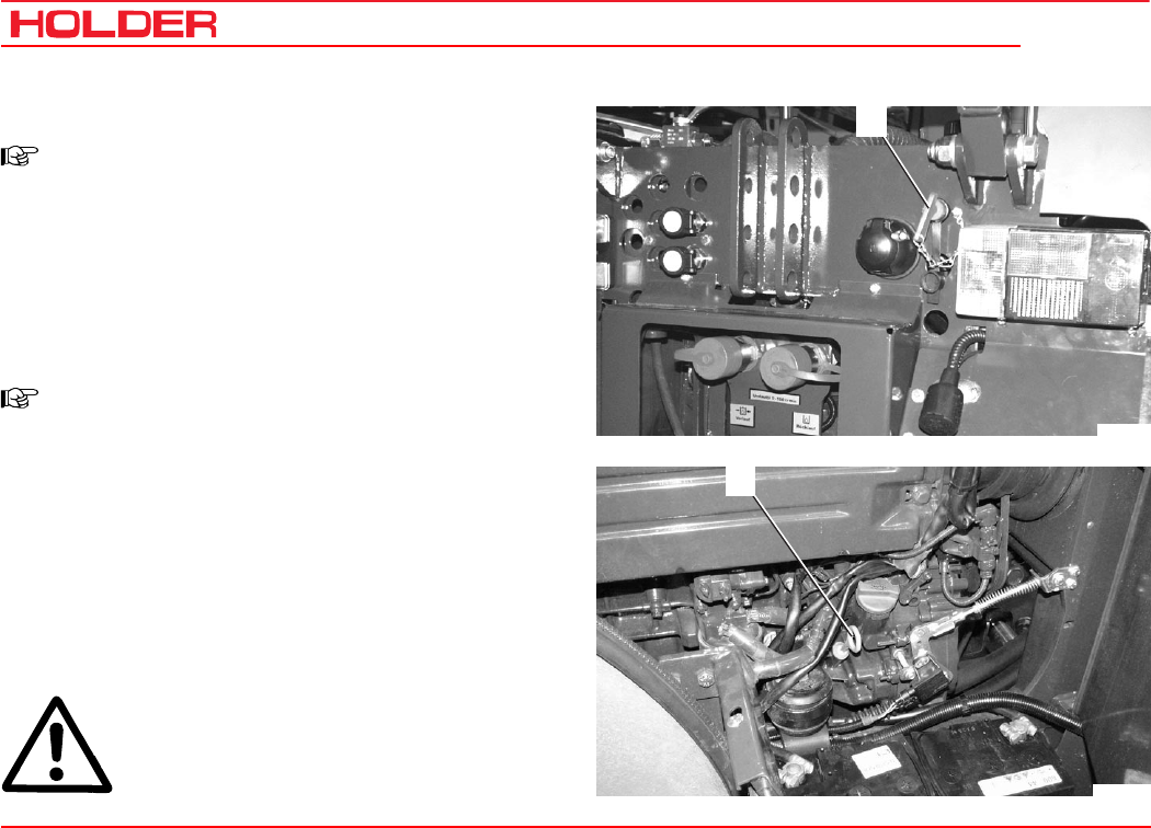
Check the engine oil level
NOTE
Check the engine oil level only when the ve-
hicle is on level ground.
- Let the engine run approx. 2 minutes with the heater
temperature control open.
- Stop the engine and pull the oil dipstick (1) out after
about 1 minute.
- The oil level should be between the minimum and
maximum marks.
- Top up oil as specified in the maintenance instructions.
ATTENTION
Do not fill too much oil.
1
Bild_C157
Bild_C227
1
Operating instructions
149 443 47
C 4.74 Taking into operation
Check the trailer hitch (option) if required
- Check the trailer hitch for proper condition and opera-
tion. Carry out the check according to the instructions
in the section “Operating the trailer hitch“.
Check the tire inflation pressure
NOTE
Your vehicle can be equipped with different types
of tires. The specified inflation pressure for your
tires is given in the table entitled “Tires“ in the
technical data section.
- Check the inflation pressure at all four tires. All tires must
have the same pressure. The rolling resistance increases
if the pressure is too low. This causes an increase in fuel
consumption and tire wear, the driving characteristics
become poorer.
DANGER
If the inflation pressure is too high, the tires
can explode.
- The tires should not be damaged or worn.
- Have damaged tires replaced without delay. Due to the
longer braking distance the risk of an accident is in-
creased.
Bild_C225
Bild_C230
C 4.74
Operating instructions
48 149 443
Taking into operation
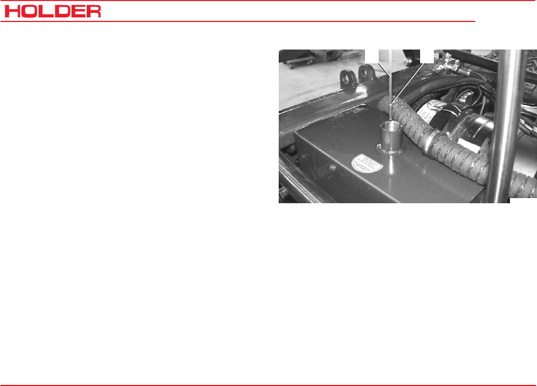
Check the hydraulic oil level
- Raise the dump body (dumper).
- Retract all hydraulic cylinders.
- Withdraw the oil dipstick (1).
- The oil level must be at the marking (2).
- Top up oil as specified in the maintenance instruc-
tions.
Bild_C226
1 2
Operating instructions
149 443 49
C 4.74 Taking into operation
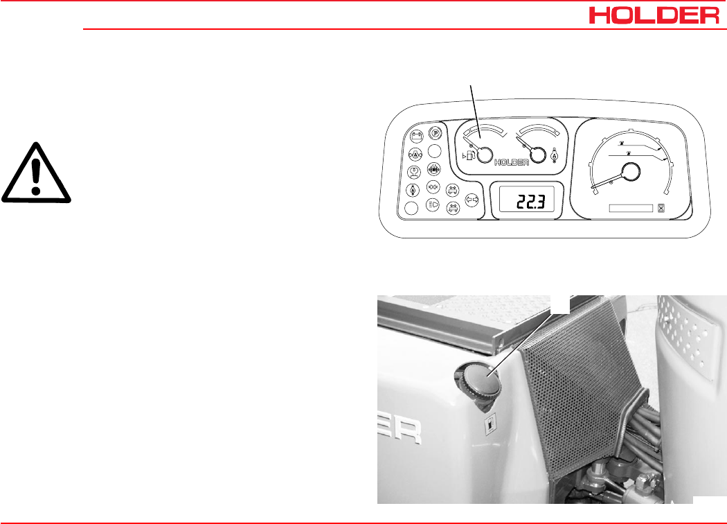
Filling fuel
- If necessary, read the fuel level (1) on the multifunc-
tional display.
CAUTION
Danger of fire when handling fuels. Turn off
the engine. Do not fill any fuels in the vicinity
of naked flames, ignition sparks or hot en-
gine parts. Do not smoke when refuelling.
- Remove the oil filler cap (2) of the fuel tank.
- Top up diesel fuel as specified in the maintenance
instructions.
Filling capacity ............................................ approx. 60 L
- Refit the filler cap (2).
2
Bild_C158
Km/h
0000000 h
25
15
FRONT
540U/min
1000U/min
20
5
10
30
RPMx100
PTO
electronic
0
Motor
digital system
1
2
1
Bild_C219
C 4.74
Operating instructions
50 149 443
Taking into operation
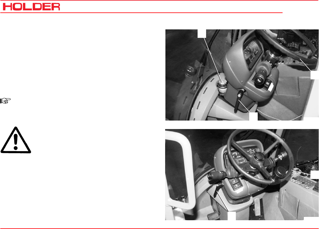
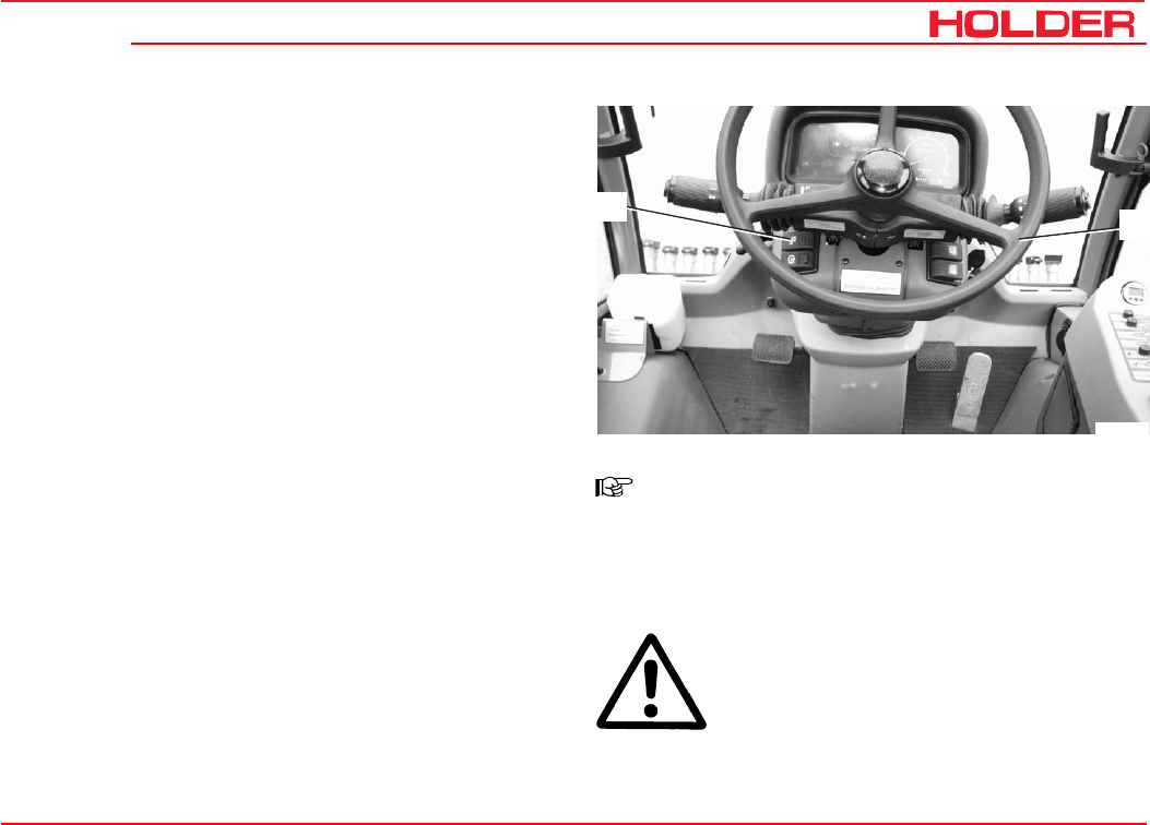
Check the brake fluid level
- Check the brake fluid level at the brake fluid reservoir
(1).
- The brake fluid level should be between the minimum
and maximum marks on the reservoir.
- Top up brake fluid as specified in the maintenance
instructions.
Adjust the steering wheel
NOTE
The angle of the steering wheel can be set to
a comfortable position.
DANGER
Do not adjust the steering wheel while driv-
ing.
- Loosen the lever (2).
- Adjust the angle and height of the steering wheel (3).
- Retighten the lever (2).
1
2
3
Bild_C159
2
3
Bild_C160
Operating instructions
149 443 51
C 4.74 Taking into operation
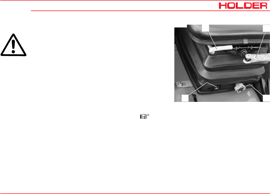
Adjust the driver’s seat with mechanical suspension
DANGER
Do not adjust the seat while driving. Risk of
accidents!
1 Horizontal adjustment
- Raise the handle (1) and push the seat to the front
or rear.
- Release the handle and allow the seat lock to
engage.
2 Weight adjustment
- Adjust the desired driver’s weight by turning the
weight adjustment lever (2).
- If the adjustment is correct, the position set at the
height adjustment handle (4) is indicated in the
window (3).
3 Height adjustment
- Three different heights can be set with the hand-
wheel (4).
- The weight should be adjusted after each height
adjustment.
NOTE
To prevent damage to your health, the indi-
vidual adjustment should be checked and
adjusted before taking the vehicle into serv-
ice.
12
43
Bild_C024
C 4.74
Operating instructions
52 149 443
Taking into operation
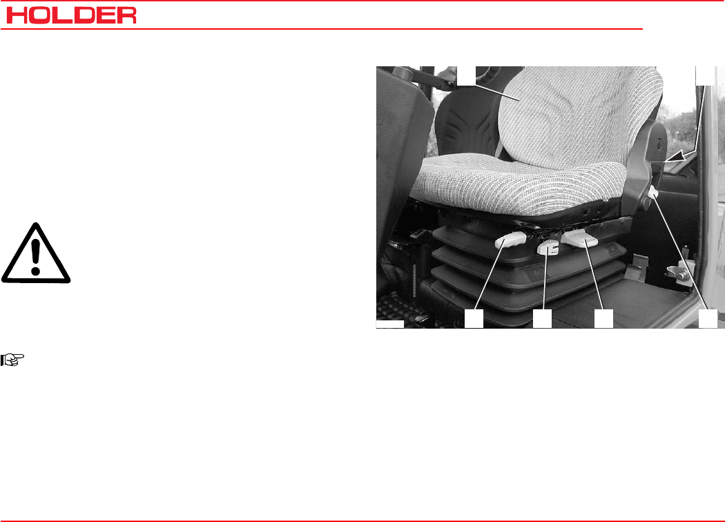
Adjusting the driver’s seat with pneumatic suspen-
sion
1 Backrest
2 Adjustment knob for lumbar padding
3 Backrest inclination
4 Weight adjustment
5 Horizontal cushioning
6 Horizontal adjustment
DANGER
Do not adjust the seat while driving. Risk of
accidents!
- Adjust the seat so that all controls can be reached
and operated safely.
NOTE
Observe the operating instructions for the
seat supplied with your vehicle.
Adjusting the lumbar padding
- Be seated on the seat and lean against the backrest
(1).
- Turn the adjustment knob for lumbar padding (2) until
the most comfortable position is reached.
12
3
456
Bild_010
Adjusting the backrest inclination
- Pull the inclination lever (3) up.
- Adjust the inclination of the backrest with your back.
- Release the inclination lever.
Operating instructions
149 443 53
C 4.74 Taking into operation
12
3
456
Bild_010
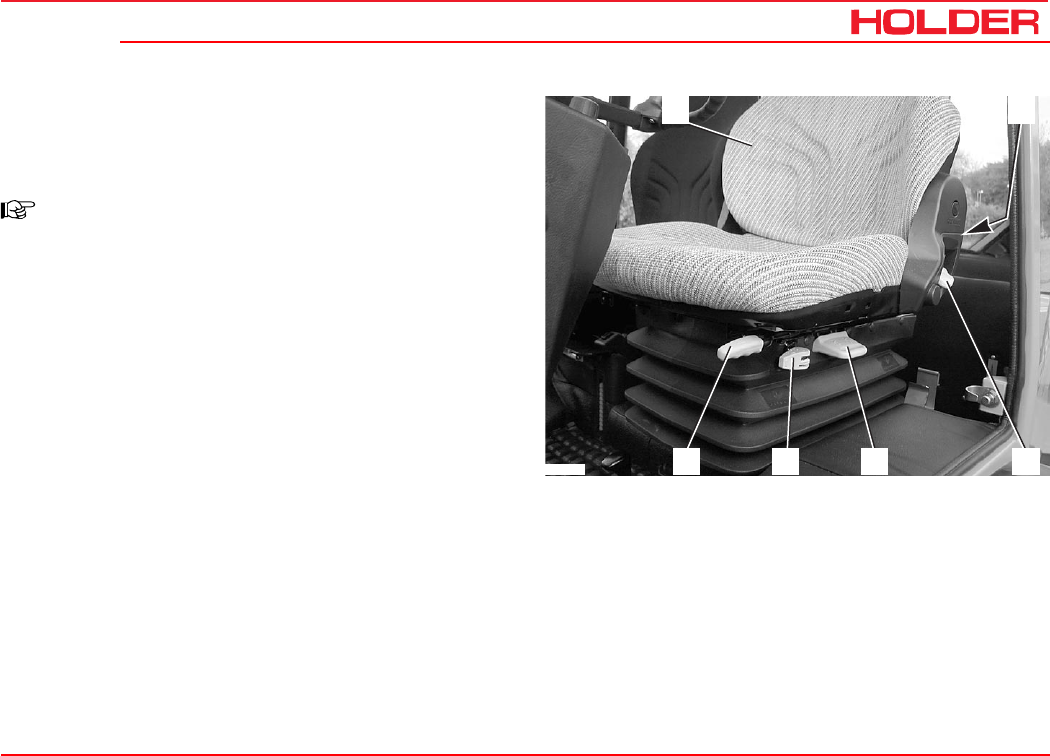
Adjusting the driver’s weight
- Sit down on the driver’s seat.
- Pull the weight adjustment handle (4) up.
NOTE
An alarm sounds. The seat is automatically
set to the weight of the driver; the alarm
ceases.
- Release the lever.
Adjusting the horizontal suspension
- Pull the horizontal suspension lever (5) back:
Seat suspension is free in the horizontal direction.
- Pull the horizontal suspension lever (4) forward:
Seat suspension is locked in the horizontal direction.
Adjusting the seat horizontally
- Pull the horizontal adjustment lever (6) up.
- Slide the seat horizontally to the front or rear to the
suitable seat position.
- Release the horizontal adjustment lever.
C 4.74
Operating instructions
54 149 443
Taking into operation
1 2
Bild_C161
Bild_C231
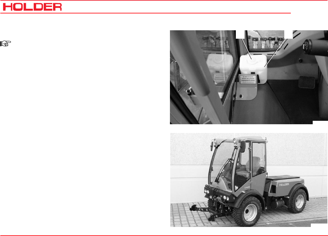
Filling washing water
NOTE
The washing water reservoir for the windshield
washer is located behind the driver’s seat.
- Open the filler cap (1) and add washing water into the
reservoir (2).
Filling quantity .......................................... approx. 1.3 L
Check the lights and rear view mirror
- Check the lights for proper operation. Carry out the
check according to the instructions in the section
entitled “Lights“
- Adjust the rear view mirror so that the roadway behind
the vehicle and the working area are easily seen.
Operating instructions
149 443 55
C 4.74 Taking into operation
Starting the engine
Notes on the engine before starting up
DANGER
Do not start or run the engine in enclosed
spaces. Danger of poisoning through exhaust
gases!
Notes on starting
CAUTION
Before starting, make sure no-one is in the
vicinity of the vehicle.
ATTENTION
Do not use any starting aids such as Startpilot
or similar products. Turn off the drive or driven
attaching implements.
CAUTION
Start the engine only from the driver’s sta-
tion.
C 4.74
Operating instructions
56 149 443
Taking into operation
2
1
3
Bild_C162
4
Bild_C163
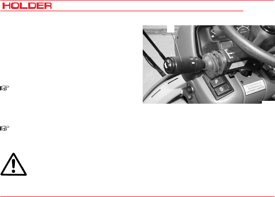
Start the engine
- Set the forward/reverse selector switch (1) to the
neutral position (centre).
- Fully depress the inching pedal (2).
NOTE
The engine can only be started if the pedal is
fully depressed (starting safety switch).
- Set the hand throttle button (4) to idle (push in fully).
- Insert the ignition key and turn the preheat/starter
switch (3) to position 1.
NOTE
The battery charging indicator (6), engine oil
pressure indicator (7), parking brake indica-
tor come on (8) (if parking brake is applied).
Operating instructions
149 443 57
C 4.74 Taking into operation
Km/h
0000000 h
25
15
FRONT
540U/min
1000U/min
20
5
10
30
RPMx100
PTO
electronic
0
Motor
digital system
1
2
5 96 78 10
Bild_C164
- Turn the ignition key to position 2.
The engine is being preheated. The preheating indica-
tor (5) comes on.
NOTE
When starting at low temperatures, hold the
ignition key longer (approx. 1 minute) in posi-
tion 2.
- When the preheating indicator extinguishes, turn the
ignition key to position 3 to start the engine.
The engine starts.
ATTENTION
Operate the starter for a maximum of 20 sec-
onds. Wait one minute before repeating the start-
ing procedure. Repeat the starting procedure only
twice at most. In case the engine does not start,
carry out a troubleshooting according to the
section entitled “Troubleshooting guide“.
- Release the ignition key after the start.
The battery charging indicator (7) and the engine oil
pressure indicator (6) extinguish.
- Set the engine speed with the hand throttle button or
accelerator pedal to the desired rpm (9).
- The hour meter (10) is activated.

C 4.74
Operating instructions
58 149 443
Taking into operation
Check the brakes and steering for proper operation
- Make a short trial run and check the steering and
brakes for proper operation.
DANGER
Do not drive a vehicle with a defective steer-
ing and/or braking system.
149 443 59
C 4.74 Operating instructions
Operation
Before starting to drive
When driving on public highways, observe the rules and
regulations of the highway code.
Driving safety rules
• Drive the vehicle only from the driver’s station with
the cab doors closed.
• Always adjust your speed to the driving conditions
and the load you are carrying.
• Never drive downhill without having the vehicle in gear
or with the engine stopped.
• Before driving, check that no-one is standing in the
immediate vicinity of the vehicle.
• The driving behaviour of the vehicle is strongly
affected by the weight and swing range of the imple-
ments, trailers and, if fitted, ballasting. Therefore
drive slowly with heavy equipment and take the longer
braking distance into consideration.
• When following a curve with a trailer or other implements,
do not forget to take the added length and drag into
consideration.
DANGER
Any parts of the implements posing a traffic
hazard must be covered before driving or
identified with warning signs.
• Switch off the differential lock in curves.
• When driving on slopes, always drive straight downhill
if possible; if you have to turn, turn only uphill.
• On steep slopes you can improve traction by activat-
ing the differential lock.
• Drive across slopes only in accordance with the notes
at the end of this chapter.
C 4.74
Operating instructions
60 149 443
Operation
1
Bild_C165
Driving
Driving with hydrostatic drive and digital electronics
- Start the engine.
- Preselect the direction of travel with the direction
switch (1).
- Pull up the forward/reverse selector switch (1) and
move it to the front or rear (forward or reverse).
NOTE
After starting the engine, the forward/reverse
selector switch must be operated once if it
was in the forward or reverse position when
starting. This prevents any accidental move-
ment of the vehicle when starting the engine.
NOTE
You can also select the new direction when
travelling at reduced speed.
CAUTION
The vehicle will brake strongly and acceler-
ate in the opposite direction.
Operating instructions
149 443 61
C 4.74 Operation
321
Bild_C166
Table of driving ranges
- Select the desired driving program with the driving
program switch (2). The selected position is illuminat-
ed:
You can select between 4 programs:
Range 1 and 2 eg on-road travel
Range 3 and 4 eg working

C 4.74
Operating instructions
62 149 443
Operation
Table of driving programs*
Position Symbol Function Utilisation
Range 0 STOP Drive off
Range 1 Rabbit symbol Maximum speed eg for highway driving
Range 2 Turtle symbol Reduced speed eg for slow on-road travel
Range 3 PTO symbol Travel speed adjustable with fine
adjustment knob, is controlled
automatically in case of high power
demand of implement
eg for mowing
Range 4** Snow blower symbol Travel speed adjustable with fine
adjustment knob, is controlled
automatically in case of high power
demand of implement
eg special setting for snow
blower
* The driving programs can be optimised for special operations by your Service, eg controlled constant driving speed
** With SDS driving comfort, the vehicle speed is controlled with the accelerator.
Operating instructions
149 443 63
C 4.74 Operation
321
Bild_C166
Km/h
0000000 h
25
15
FRONT
540U/min
1000U/min
20
5
10
30
RPMx100
PTO
electronic
0
Motor
digital system
1
2
45
Bild_C167
Selecting on-road travel (transport speed)
The vehicle is stationary.
- Set the program switch (2) to range 1 or 2.
NOTE
The driving range can also be switched while
driving at reduced speed.
- Release the parking brake.
- Depress the accelerator pedal for the desired speed.
The vehicle starts and can be driven up to the maxi-
mum speed of the chosen range.
- You can read the engine speed (5) and driving speed
(4) on the multifunctional display.
Setting the working speed of programs 3 and 4
NOTE
With programs 3 and 4 you can select the
driving speed independent of the PTO rpm.
C 4.74
Operating instructions
64 149 443
Operation
321
Bild_C166
The vehicle is stationary.
- Set the fine control knob (1) to 0.
- Set the program switch (2) to range 3 or 4.
- Adjust the PTO rpm with the hand throttle (3).
NOTE
The engine speed must reach at least 1500
rpm as the control is only effective beginning
at this speed.
NOTE
You can also switch ranges while driving.
The ranges 3 and 4 provide a speed as required by the load
on the PTO. This means that if, for example, the snow blower
requires more power when meeting high resistance, the
vehicle will drive more slowly. As the resistance decreases,
the vehicle accelerates again to the previously selected
driving speed. Driving range 4 is especially adapted for cer-
tain applications.
- Release the parking brake.
- The driving speed is controlled with the fine control
knob (1).

Operating instructions
149 443 65
C 4.74 Operation
321
Bild_C166
Adjusting the fine control knob
NOTE
You can adjust the fine control knob (1) at
any time while driving for fine and infinitely
variable control of the driving speed.
- In position 0 the vehicle is stationary. When turned
further clockwise, the vehicle starts driving and at the
maximum scale position 11, the maximum speed of
the driving range is achieved.
- You read can the engine speed and driving speed on
the multifunctional display.
NOTE
In this operating mode, the vehicle drives
automatically and needs only to be steered.
This mode is best for operating an implement as you can
concentrate fully on controlling the implements.
C 4.74
Operating instructions
66 149 443
Operation
321
Bild_C166
4
Bild_C168
Driving with SDS (Special Drive System)
For setting programs 1-3 with the program switch (2) see
the operation section on pages 61 and 62.
Driving program 4 (SDS)
- Set the program switch (2) to driving range 4.
NOTE
At this level the fine control knob (1) is not
working. The function is assumed by the pedal
(4).
- Adjust the engine rpm with the hand throttle (3).
- You can now control the vehicle speed steplessly with
the pedal (4) (accelerator).
Operating instructions
149 443 67
C 4.74 Operation
8
7
Bild_C169
9
Bild_C170
Operating the inching pedal
7 Inching pedal
8 Accelerator pedal
This function is active for all driving programs.
NOTE
The inching pedal allows driving speed to be
reduced temporarily.
- Depress the inching pedal (7) to reduce driving speed
and to stop completely.
- Release the inching pedal again after passing the
obstacle.
The vehicle will resume the previously selected
speed.
Changing the direction of travel
- Preselect the new direction with the forward/reverse
selector switch (9).
- The vehicle will come to a standstill and accelerate
again in the opposite direction.
C 4.74
Operating instructions
68 149 443
Operation
Km/h
0000000 h
25
15
FRONT
540U/min
1000U/min
20
5
10
30
RPMx100
PTO
electronic
0
Motor
digital system
1
2
2
Bild_C172
1
Bild_C276
Engaging the differential lock
NOTE
With the differential lock you can improve trac-
tion on soft, slippery ground. The engine
speed should be over 1000 rpm during its use.
You can engage the differential lock only
briefly by toggling the switch momentarily.
ATTENTION
The differential lock may only be used when
driving straight ahead.
- Depress the rear end of the differential lock switch (1)
and hold it.
The indicator (2) in the multifunctional display lights
up red. An intermittent alarm sounds at the same
time.
The differential lock acts on both axles.
Disengaging the differential lock
- Release the differential lock switch (1).
The indicator (2) goes out and the alarm in the multi-
functional display ceases.
Operating instructions
149 443 69
C 4.74 Operation
21
Bild_C173
Steering
The vehicle has a hydraulically-operated articulated steer-
ing. The wheels also stay in track in curves so that imple-
ments are guided without any lateral offset.
Steering
- Turn the steering wheel (1) in the desired direction.
The possible turning radii depend on the tires and track widths
of your vehicle. For exact information refer to the track width
table in the section „Technical data“.
Two-stage steering*
The vehicle can be driven with two steering speeds.
- Indirect steering (travel mode- slow steering speed)
- Direct steering (working mode - fast steering speed)
- Depress the toggle switch (2) on the left. The indica-
tor light in the toggle switch comes on and the steer-
ing for the working mode is turned on.
NOTE
With direct steering the steering lock is about
twice as large as with indirect steering for
the same steering movement.
(ratio approx. 1:2)
ATTENTION
For on-road travel the two-step steering must
be set to indirect steering (indicator light off)
(danger).
* Option
C 4.74
Operating instructions
70 149 443
Operation
2
Bild_C174
1
Km/h
0000000 h
25
15
FRONT
540U/min
1000U/min
20
5
10
30
RPMx100
PTO
electronic
0
Motor
digital system
1
2
3
Bild_C175
Brakes
The service brake is a drum brake mounted in the front axle
and it is actuated hydraulically. The parking brake is applied
with the parking brake switch.
Applying the service brake
- Depress the brake pedal (1).
Applying the parking brake
ATTENTION
The parking brake is not intended to be used
for braking while driving.
- Unlock the lock at the parking brake switch (2) and
depress the switch to the left.
The parking brake is applied and the indicator light in
the switch and the parking brake warning light (3) in
the multifunctional display come on.
Operating instructions
149 443 71
C 4.74 Operation
2
Bild_C174
1
Km/h
0000000 h
25
15
FRONT
540U/min
1000U/min
20
5
10
30
RPMx100
PTO
electronic
0
Motor
digital system
1
2
3
Bild_C175
Releasing the parking brake
- Turn off the parking brake switch (2).
The parking brake is released and the indicator light in
the switch and the parking brake warning light (3) go
out.
- If the parking brake warning light (3) in the multifunc-
tional display comes on with the parking brake re-
leased, there is too little pressure for releasing the
parking brake in the pressure accumulator.
- Start the engine to build up pressure to release the
parking brake.
ATTENTION
An alarm is sounded when driving with the
hand brake applied.
C 4.74
Operating instructions
72 149 443
Operation
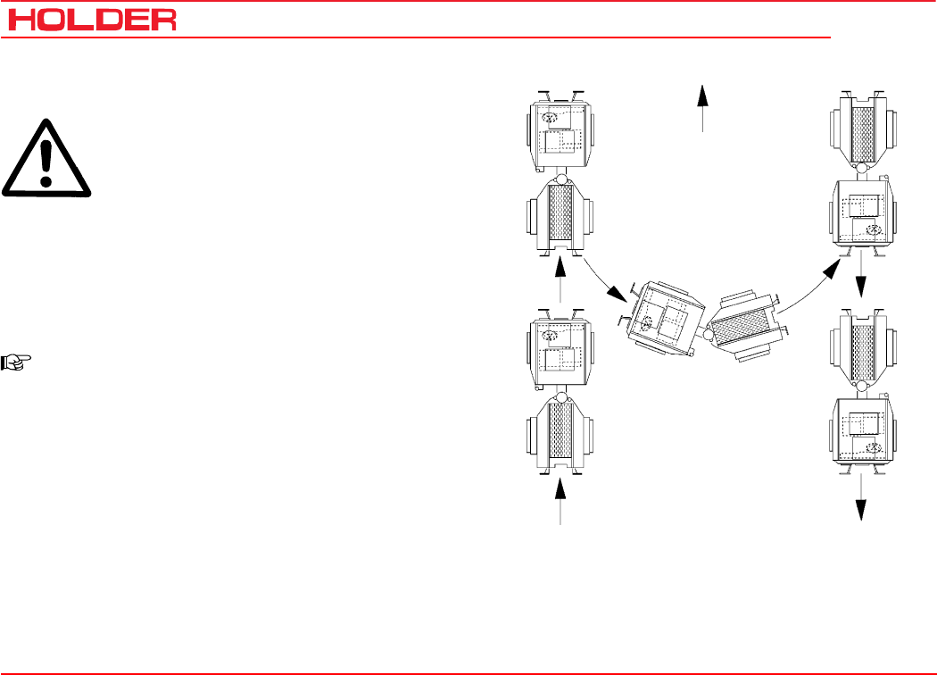
Driving on slopes
DANGER
Driving on slopes is dangerous as the vehi-
cle can tip over if the centre of gravity ex-
ceeds the tip-over limit on an extreme slope.
The following factors reduce the hazard:
- small or no load
- low driving speed
- low gradient
- low tire inflation pressure
NOTE
The driving comfort and the traction of the
vehicle can be improved by reducing the in-
flation pressure.
- large track width
- level, non-bumpy terrain
When turning on slopes we recommend proceeding as
shown in the drawing on the right.
Uphill
149 443 73
C 4.74 Operating instructions
Bild_C232
1
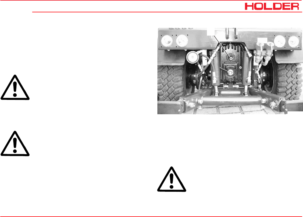
Special operating instructions
Stationary operation
The vehicle can be used for stationary operation, for example,
to drive a water pump via the PTO shaft.
ATTENTION
Place the vehicle n level ground in both di-
rections.
- Attach the stationary equipment to the PTO shaft (1).
- Set the program switch to 0.
- Operate the parking brake.
DANGER
Before switching on the PTO, make sure no-
one is standing in the vicinity of the vehicle
and the rotating PTO shaft.
Removal of hydraulic oil for stationary operation
When the vehicle is stationary, hydraulic oil can be removed,
for example, for the operation of a hydraulic dump.
Max. quantity of oil removed .................................. 12 L
ATTENTION
Before starting to drive after stationary opera-
tion, first check if the power steering is work-
ing. Turn the steering wheel fully to the right
and left several times to release air from the
steering system.

C 4.74
Operating instructions
74 149 443
Special operating instructions
Adjusting the track width
You can adjust the track width of the vehicle by mounting
the wheels inside out.
DANGER
Observe the safety notes on a safe shutdown
and jacking up for the wheel change in the
maintenance instructions.
- Remove the wheels. Turn the wheels inside out, or
from the left to the right.
NOTE
The arrows on the tires must show in the for-
ward direction of rotation again.
- Tighten the wheel nuts to the specified torque.
Torque................................................................. 215 Nm

Operating instructions
149 443 75
C 4.74 Special operating instructions
Operation in winter
Oil preheating*
Before starting the engine at temperatures below -20°C, turn
on the heating element* to preheat the oil.
- Connect the preheating system plug to a 230 VAC source.
Observe the operating instructions of the battery manufacturer.
Winter diesel fuel
Whenever temperatures fall below 0°C, use winter diesel or
super diesel fuel or additives recommended in the mainte-
nance instructions.
Engine oil for winter operation
Fill engine oil with a suitable SAE class as recommended
the maintenance instructions.
The cold start capability of the engine can be reduced if the
temperature limits are underrun occasionally, but this does
will not damage the engine.
Hydraulic system
The hydraulic functions are sluggish and slower during cold
temperatures. Bring the hydraulic system to operating tem-
perature with some movements without a load.
Putting on snow chains
Snow chains can be mounted on the tires to improve grip.
In the following table you will find the order numbers for
RUD chains which fit on the listed tires. You can also fit
snow chains from other manufacturers if these have the
proper dimensions.
Tires Snow chain type
(RUD Order No.)
10.5-18 MPT / 10.5/80-18 22 553 and 24 553
275/70 R18 / 320/65 R18 24 553
31x11.50 R15 22 055
31x15.50-15 Terra 24 548
33x12,50 R15 22 167 and 24 167
33x15.50-15 22 174
36x13.5-15 24 178
Ballast weights
The weight of the machine can be increased with ballast
weights. The same ballast weights must be mounted on
each axle and side.
* Option
149 443 77
C 4.74 Operating instructions
Operating the implements
We have tested and approved a large number of possible
implements for use with this vehicle. Only implements with
the CE symbol may be used. We recommend contacting
our customer service before installing special equipment.
Possible implements
For example for:
vineyards and orchards
agriculture
mowers
snow fighting equipment
and other street cleaning equipment.
Safety instructions for handling implements
The vehicle must be parked safely before the installation of
implements.
It must be secured against rolling, for example, with the park-
ing brake or, if required, with chocks.
DANGER
Be careful when attaching implements: risk of
injury by pinching and shearing parts.
DANGER
No persons are allowed to stand between the
vehicle and implement when the vehicle is not
secured against rolling.
For driving on roads the implement must be
lifted and secured against lowering.
Observe the applicable safety regulations for
your implement. Observe the operating in-
structions and the safety rules for your im-
plement.
DANGER
During work breaks, the implement must al-
ways be lowered to the ground in order to
relieve the hydraulic cylinders. Accidents can
occur if the lowering is uncontrolled, for ex-
ample, due to damage or accidental move-
ment of the control levers.
DANGER
Any parts of the implements posing a traffic
hazard must be covered before driving or
identified with warning signs.
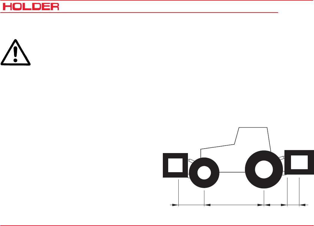
C 4.74
Operating instructions
78 149 443
Operating the implements
GvGH
TvTH
abcd
Additional information on implements
Do not exceed the permissible total weight,
the permissible axle loads and tire carrying
capacities of the vehicle when installing im-
plements on the front and rear 3-point lift. The
front axle of the vehicle must always be loaded
with at least 20 % of the vehicle’s kerb weight.
Before purchasing equipment, make sure these
conditions are met by performing the following
calculations or by weighing the vehicle-equip-
ment combinations.
Determining the total weight, axle loads and tire carry-
ing capacity including the minimum ballasting.
For their calculation you need the following data:
TL(kg) Kerb weight of the vehicle 1)
TV(kg) Front axle load of the empty vehicle 1)
TH(kg) Rear axle load of the empty vehicle 1)
GH(kg) Total weight of
rear implement/rear ballast 2)
GV(kg) Total weight of
front implement/front ballast 2)
a (m) Clearance between centre of gravity
of front implement/front ballast and
centre of front axle 2) 3)
b (m) Vehicle wheelbase 1) 3)
c (m) Distance between centre of rear axle
and centre of lower link ball 1) 3)
d (m) Distance between centre of
lower link ball and centre of gravity of
rear implement/rear ballast 2)
1) See technical data in the operating instructions
2) See price list and/or operating instructions of the implement
3) Measure

Operating instructions
149 443 79
C 4.74 Operating the implements
Rear implement or front/rear combinations
1) Calculation of the minimum front ballasting GV min
G
V
min=
G
H
·
(c+d)-T
V
·b
+0.2·
T
L
·b
a
+
b
Enter the calculated minimum ballasting required for the
front of the vehicle in the table.
Front implement
2) Calculation of the minimum rear ballasting GH min
G
H
min=
G
V
·a-T
H
·
b
+
X·T
L
·
b
b
+
c
+
d
Enter the calculated minimum ballasting required for the
rear of the vehicle in the table.
(Value X for Holder vehicle 0.25 4-wheel)
3) Calculation of the actual front axle load TV tat
(If the minimum front ballasting (GV min) is not obtained with
the front implement (GV) , the weight of the front implement
must be increased to the weight of the minimum front
ballasting.)
T
V
tat=
G
V
·(a
+
b)
+
T
V
·b-G
H
·(c
+
d)
b
Enter the calculated actual and the permissible front axle
load specified in the operating instructions of the vehicle in
the table.
4) Calculation of the actual total weight Gtat
(If the required minimum rear ballasting (GH min) is not ob-
tained with the rear implement (GH min), the weight of the rear
implement must be increased to the weight of the minimum
rear ballasting.)
G
tat=
G
V
+
T
L
+G
H
Enter the calculated actual and the permissible total weight
specified in the operating instructions of the vehicle in the
table.
5) Calculation of the actual rear axle load TH tat
T
H tat
=
G
tat
-
T
V tat
Enter the calculated actual and the permissible rear axle
load specified in the vehicle operating instructions in the
table.

C 4.74
Operating instructions
80 149 443
Operating the implements
6) Tire carrying capacity
Enter the double value (two tires) of the permissible tire
carrying capacity (eg see tire manufacturer documentation)
in the table.
Actual Calculated Weight
Specified Permissible
Weight acc. to operating
instructions
Double Permissible Tire
Load Capacity
(Two Tires)
Minimum ballast at
front/rear / kg - -
Total weight kg ≤kg -
Front axle kg ≤kg ≤kg
Rear axle kg ≤kg ≤kg
The minimum ballasting must be mounted on the tractor either as attachment or ballast weight!
The calculated weights must be lower than/equal to (≤) the permissible weights!

Operating instructions
149 443 81
C 4.74 Operating the implements
Attaching implements
The various implements are attached to the front or rear
power lift*.
There are 2 different fastening categories:
Category I Pin diameter 22 mm
Category II Pin diameter 28 mm
The vehicle can be adjusted to both categories by adjusting
the pintle hook bars and providing the pintle hooks with or
without reducer sleeves.
DANGER
Only use the following specified devices for
attaching your implement.
Secure the implement against shifting or roll-
ing.
* Option
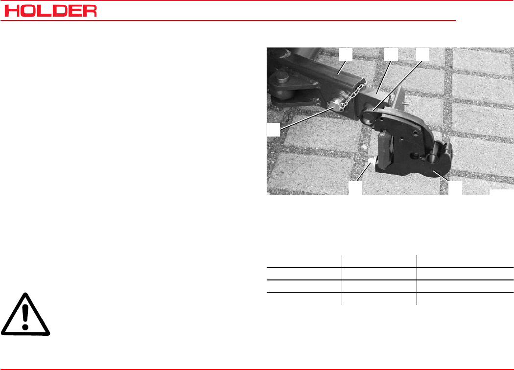
C 4.74
Operating instructions
82 149 443
Operating the implements
234
6
1
5
Bild_C233
Adjusting the pintle hooks and pintle hook bars
You can adjust the pintle hooks laterally and longitudinally.
- Measure the stand-off of the pins on your implement.
- Loosen the clamping screws (6) on both sides.
- Slide the pintle hooks laterally until the required
distance is reached.
- Retighten the clamping screws.
- Equipment of category IIcan be attached with the
pintle hooks (5) directly.
- For equipment of category I install the reducing
sleeves on the left and right side.
Adjusting the length of the pintle hook bar
- Loosen the 2 locknuts and clamping screws (inside
and at bottom) on the lower link (2).
- Pull the retaining clip out of the pin (1) and remove
the pin.
- You can put the pintle hook bar (3) in one of 3 posi-
tions.
- Insert the pin (1) in the hole and secure with the
retaining clip.
- Retighten the locknuts and clamping screws.
DANGER
Make sure no-one is standing between the
vehicle and implement.
- Drive the vehicle to the implement to be attached.
1 Pin with retaining clip 4 Catch
2 Lower link support 5 Pintle hook
3 Pintle hook bar 6 Clamping screw
(adjustable) with 3 positions
- Steer the pintle hooks (5) under the attaching pin of the
implement.
- Raise the front power lift until the catch (4) closes and
engages.
Hole Position Used for
1st hole Front Category I and II
2nd hole Centre Category I
3rd hole Rear Optional attachments
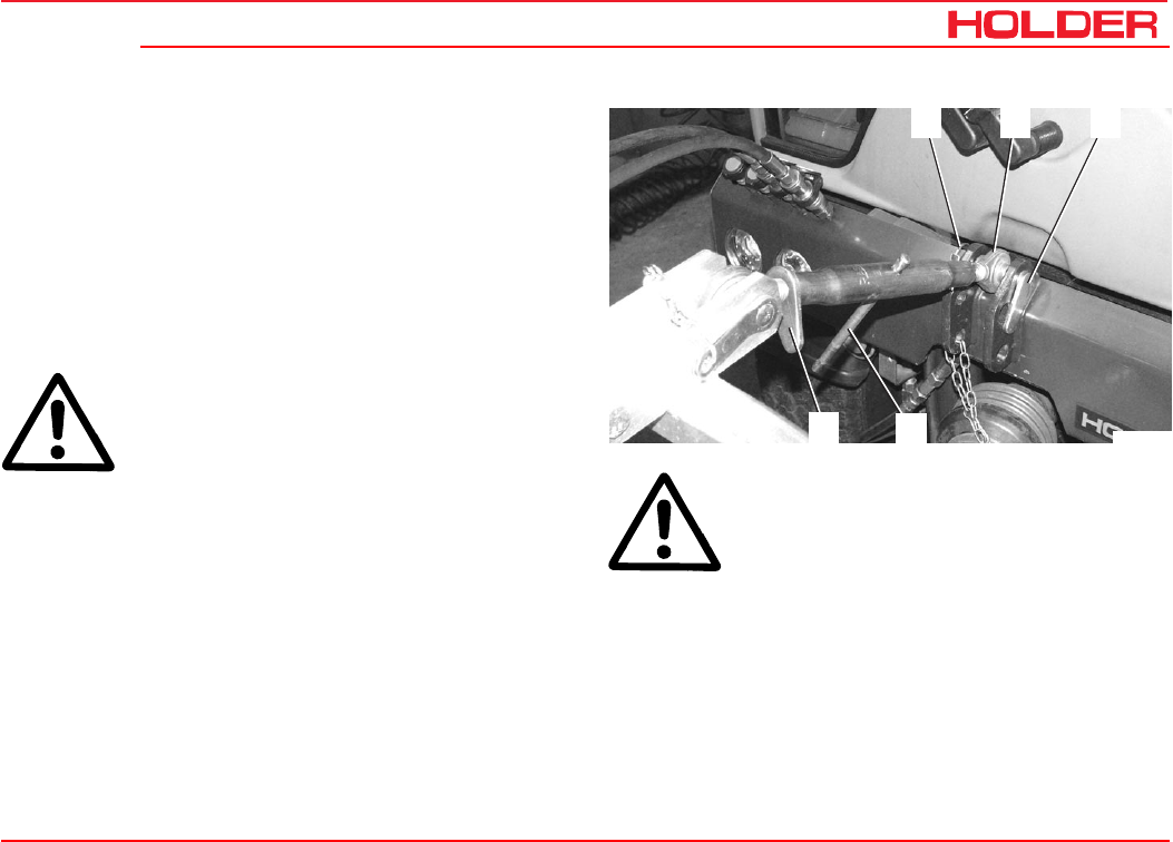
Operating instructions
149 443 83
C 4.74 Operating the implements
Bild_C268
12 3
4
5
Adjusting the upper link
The upper link can be secured at different holes. The re-
quired height depends on your implement (for a better adap-
tation of the equipment, to increase the lifting force and
depending on the lifting height).
Upper hole
• More lifting power, lower lifting height.
Lower hole
• Lower lifting power, higher lifting height.
ATTENTION
The equipment must not hit the cabin.
1 Retaining clip
2 Top link
3 Top link pin
4 Toggle
5 Locking lever
- Secure the top link (2) with the pin (3) and secure the
pin with the retaining clip (1).
- Adjust the top link (2) to the required length (by turning
the toggle (4) to screw it in or out); secure the top link
with the locking lever (5).
ATTENTION
Both threads must be screwed in equally far.
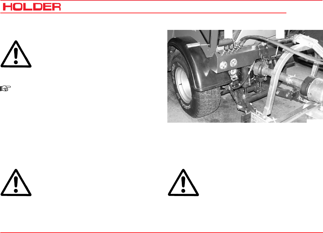
C 4.74
Operating instructions
84 149 443
Operating the implements
Bild_C266
12
Connecting hydraulic lines
ATTENTION
The hydraulic couplings on the vehicle must
not carry any pressure before the connection
is made. The couplings on the vehicle and
the hydraulic hoses must be clean.
NOTE
Each implement has different functions and
hydraulic lines to the control unit. Observe
the operating instructions supplied with your
implement and make yourself familiar with
the functions and colour codes.
- Open the protective caps of the hydraulic couplings (1).
- Attach the colour coded hydraulic hoses (2) of the
implement to the hydraulic couplings of the same
colour on the vehicle.
ATTENTION
The hydraulic male couplings fit on each cou-
pling and can therefore be connected incorrectly.
With the connection you decide which func-
tion/movement of the implement is actually
to be performed with the control lever as-
signed to the coupling.
DANGER
If you are not sure about the functions, de-
termine them by making trials at a safe place.
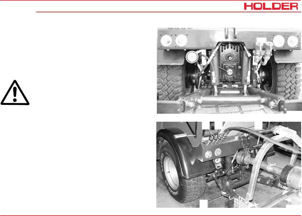
Operating instructions
149 443 85
C 4.74 Operating the implements
Bild_C234
Bild_C267
4 2
3
1
Installing the cardan shafts
Only use shafts suitable and intended for the implement.
These shafts are supplied with the implement. The length
the of the shaft must be adjusted before the first installa-
tion. In case of doubt, please contact our after-sales serv-
ice. Observe installation instructions for the cardan shaft
when installing it.
DANGER
Shut off the engine before the installation. Fit
the protective devices as specified after the
installation.
Removing implements
- Drive the implement to its storage place and lower it
with the front power lift.
- Stop the engine, but do not turn the ignition off.
- Operate all control levers for the front power lift several
times in all directions. This will relieve the pressure in
the hydraulic system.
- Slide the outer ring of the hydraulic couplings (1) back
and disconnect the hydraulic hoses (2).
- Close the protective caps on the hydraulic couplings
(as with item 4).
- Remove the upper link from the pin of the upper link
support.
- Pull the catches (3) up to release the implement pins.
- Lower the front power lift and drive forward carefully.
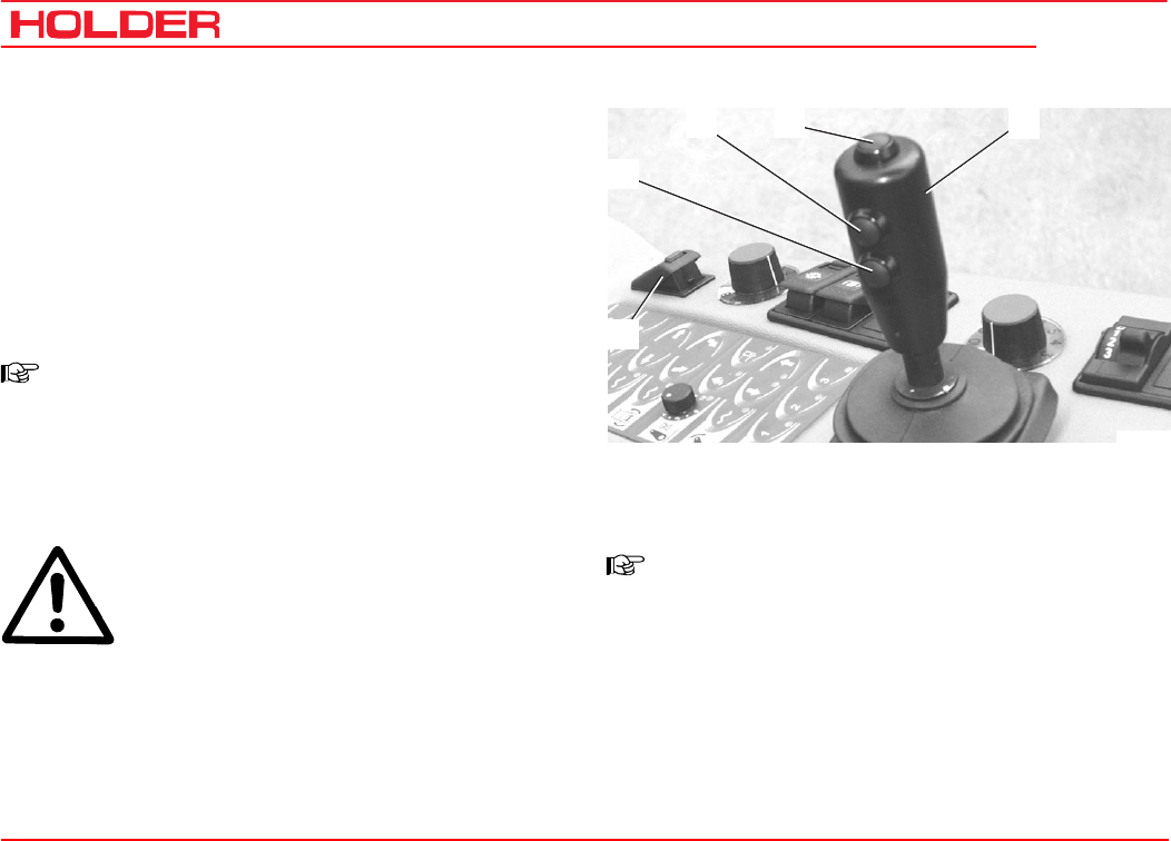
C 4.74
Operating instructions
86 149 443
Operating the implements
4
32
5
1
Bild_C176
Operating the joystick
1 Pushbutton 1 for joystick level 1
2 Pushbutton 2 for joystick level 2
3 Pushbutton 3 for joystick level 3
4 Joystick (joystick level 0 without pushbutton opera-
tion)
5 Main switch for working hydraulic system
NOTE
The joystick controls those functions of the
implements which are connected to the front
or rear hydraulic couplings. The couplings and
notice plates for the joystick are colour coded,
ie the colours and the function are matched.
DANGER
Due to the variety of implements and con-
nections, however, we recommend a trial run
of the movement at a safe place without dan-
ger to persons or risk of material damage
before starting operation.
The function of the joystick can only be carried out if the
main switch (5) is turned on.
NOTE
The joystick can be operated forward and
back as well as to the right and left: The func-
tions are shown on the notice plate.

Operating instructions
149 443 87
C 4.74 Operating the implements
Joystick operation
(Proportional, for sensitive operation).
Joystick direction
Longitudinally (forward / back) Across (left / right)
Joystick level 0
(without button)
Front power lift Y0
Forward: lowering
Back: lifting
Float position on keyboard
Front right quick coupling X0
Float position X0 on keyboard 2
Joystick level 1
(with button 1 pressed)
Dumper / rear power lift * Y1
Forward: lowering
Back: lifting
Float position Y1 on keyboard 1
Front right quick coupling X1
Float position X1 on keyboard 3
Joystick level 2
(with button 2 pressed)
Front left quick coupling Y2
No float position planned
Rear left quick coupling X2
No float position planned
Joystick level 3
(with button 3 pressed)
Tilting front power lift Y3
(included in front power lift)
Forward: tilt to the right
Back: tilt to the left
Sideshifting of front power lift X3
Alternative: quick coupling
Left: swing to the left
Right: swing to the right
* Selectable with 3-port cock
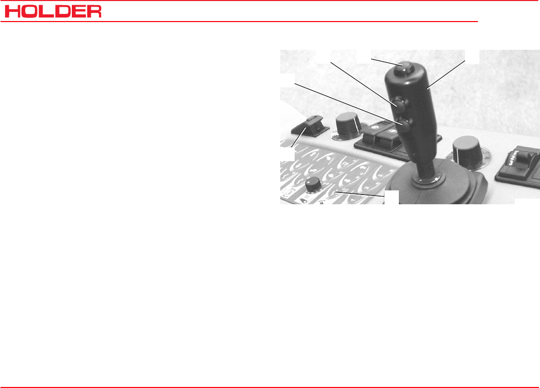
C 4.74
Operating instructions
88 149 443
Operating the implements
4
32
5
6
1
Bild_C177
Operating the front power lift
The following movements are possible:
Turn on the main switch (5) for working hydraulics.
- Push the joystick (4) forward.
• The front power lift (implement) is lowered.
You can stop the movement by releasing the joystick.
- Pull the joystick (4) back.
• The front power lift (implement) is raised.
The float position is turned on with the keyboard.
- To turn it on, press button (6). The red LED comes
on.
• The float position of the front power lift is
turned on, ie the implement can be moved by
external force.
- Press button (6) to turn it off. The red LED goes off.
Tilting the front power lift
- Hold button (3) depressed and push the joystick (4)
forward.
• The front power lift tilts to the right.
- Keep button (3) depressed and pull the joystick (4)
back.
• The front power lift tilts to the left.
Sideshifting the front power lift
- Hold button (3) depressed and push the joystick (4)
forward.
• The front power lift pivots to the right.
- Hold button (3) depressed and push the joystick (4)
forward.
• The front power lift pivots to the left.
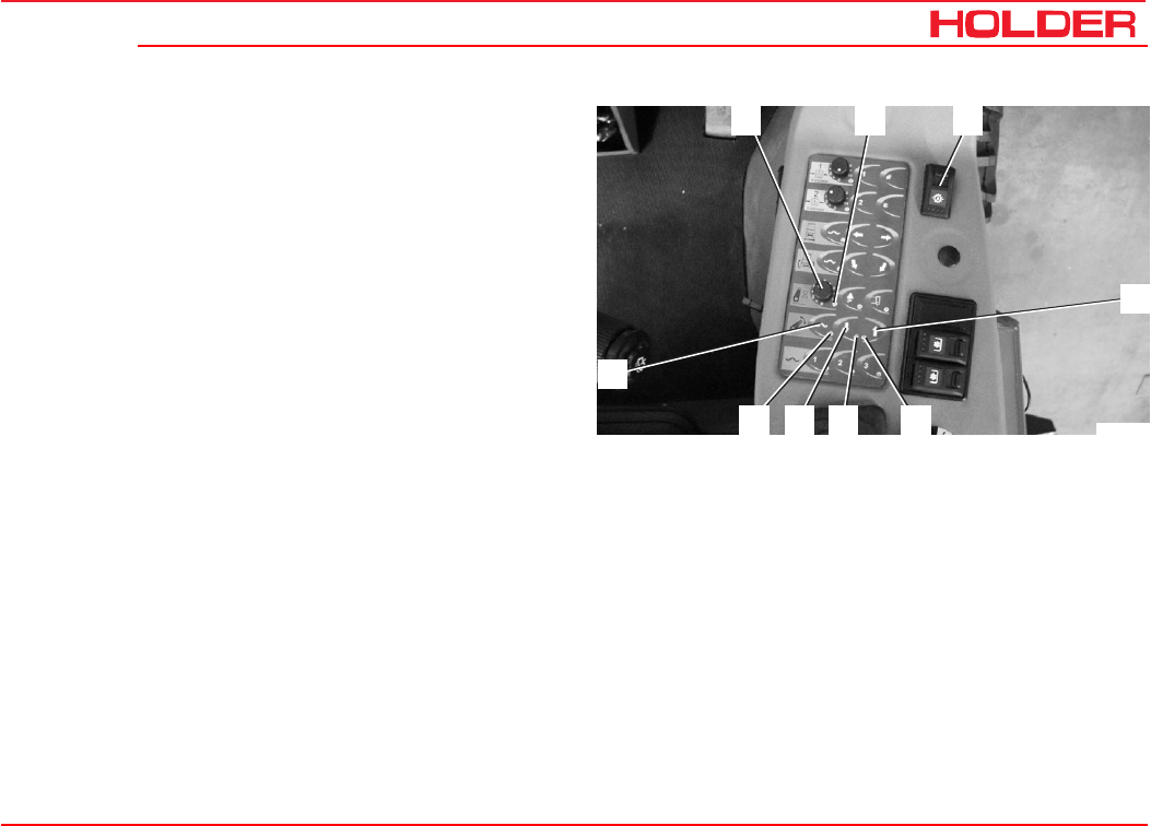
Operating instructions
149 443 89
C 4.74 Operating the implements
4
2 31
9
678 5
Bild_C178
Operating the front power lift with keyboard
The following movements are possible:
Turn on the main switch (3) for working hydraulics.
- Keep button (4) depressed for about 1 second. The
red LEDs (5 and 2) come on for about 5 seconds.
• The front power lift (implement) is raised
until the LEDs go off.
You can stop the movement by pressing the button (4,7) or
by moving the joystick.
- For lowering press button (7) for about 1 second. The
red LEDs (6 and 2) come on.
• The front power lift (implement) is lowered until the
LEDs go off.
The lifting and lowering speed can be adjusted with the set
knob (1).
- Turn rotary knob (1) to the left - slower.
- Turn rotary knob (1) to the right - faster.
You can also select the float position:
- For selection press button (9) for about 1 second. The
red LED (8) comes on.
• The float position of the front power lift is
turned on, ie the implement can be moved by
external force.
- Press button (9,7 or 4) or move the joystick to turn it
off. The red LED (8) goes off.
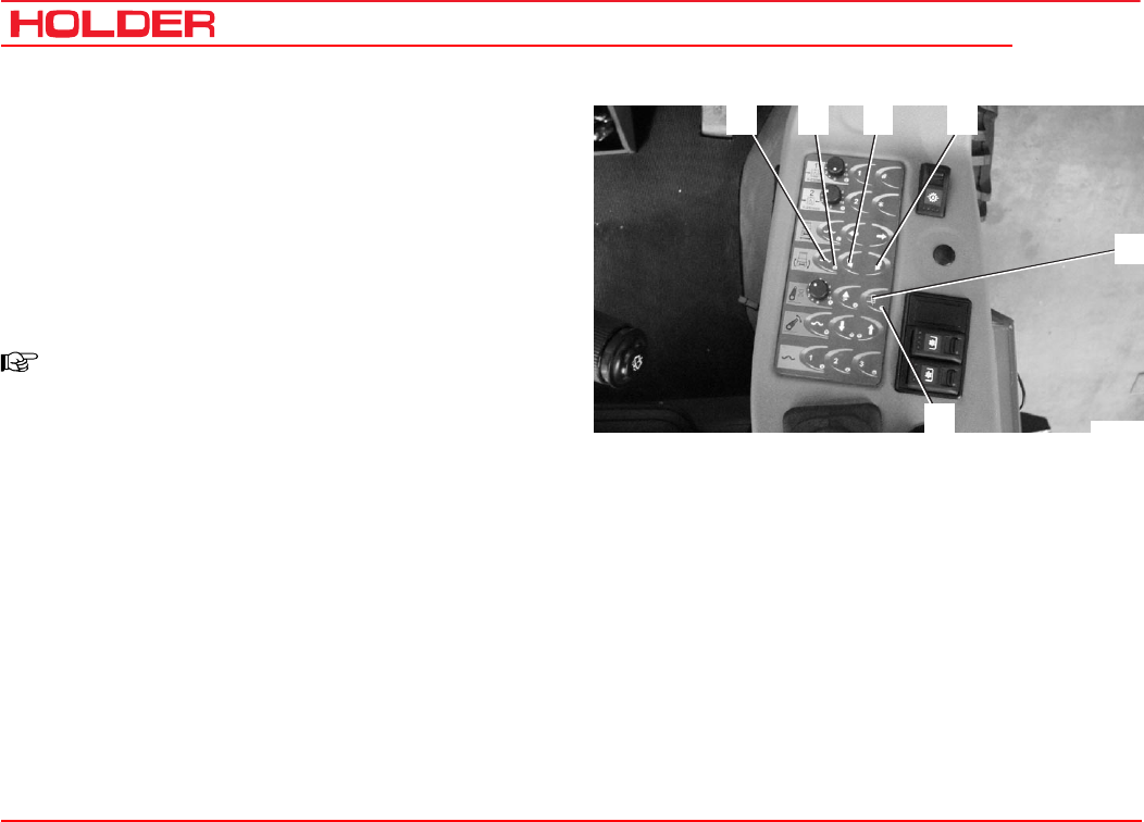
C 4.74
Operating instructions
90 149 443
Operating the implements
5
32 41
6
Bild_C179
Switching the front power lift to double-acting
The front power lift can be switched from single-acting to
double-acting.
- To switch to double-acting press button (5). The red
LED (6) goes off.
- To switch to single-acting toggle button (5). The red
LED (6) comes on.
NOTE:
The front power lift is always single-acting
when the vehicle is started or when the main
switch for the working hydraulic system is
turned on.
Operating the tilting device with the keyboard
- Keep button (4) depressed.
• The front power lift tilts to the right.
You can stop the movement by releasing the button.
- Keep button (3) depressed.
• The front power lift tilts to the left.
- Press button (1). The red LED (2) comes on.
• The float position of the tilting device is turned on,
ie the implement can be moved by external force.
- Press button (1,3 or 4) or move the joystick to turn it
off. The red LED (2) goes off.

Operating instructions
149 443 91
C 4.74 Operating the implements
32 4 51
Bild_C180
Operating the sideshift with the keyboard
- Keep button (4) depressed.
• The front power lift pivots to the right.
You can stop the movement by releasing the button.
- Keep button (3) depressed.
• The front power lift pivots to the left.
- Press button (1) for about 1 second. The red LED (2)
comes on.
• The float position of the sideshift is turned on, ie
the implement can be moved by external force.
- Press button (1,3 or 4) or move the joystick to turn it
off. The red LED (2) goes off.
Transport safety
The joystick and keyboard movements can be locked with
the main switch (5):
- Main switch off - joystick movement and keyboard
disabled
- Main switch on - joystick movement and keyboard
enabled
NOTE
When joystick movement is disabled, you can
prevent the implement from being moved
through unintentional contact with the joystick
or keyboard.
Transport lock for on-road travel.
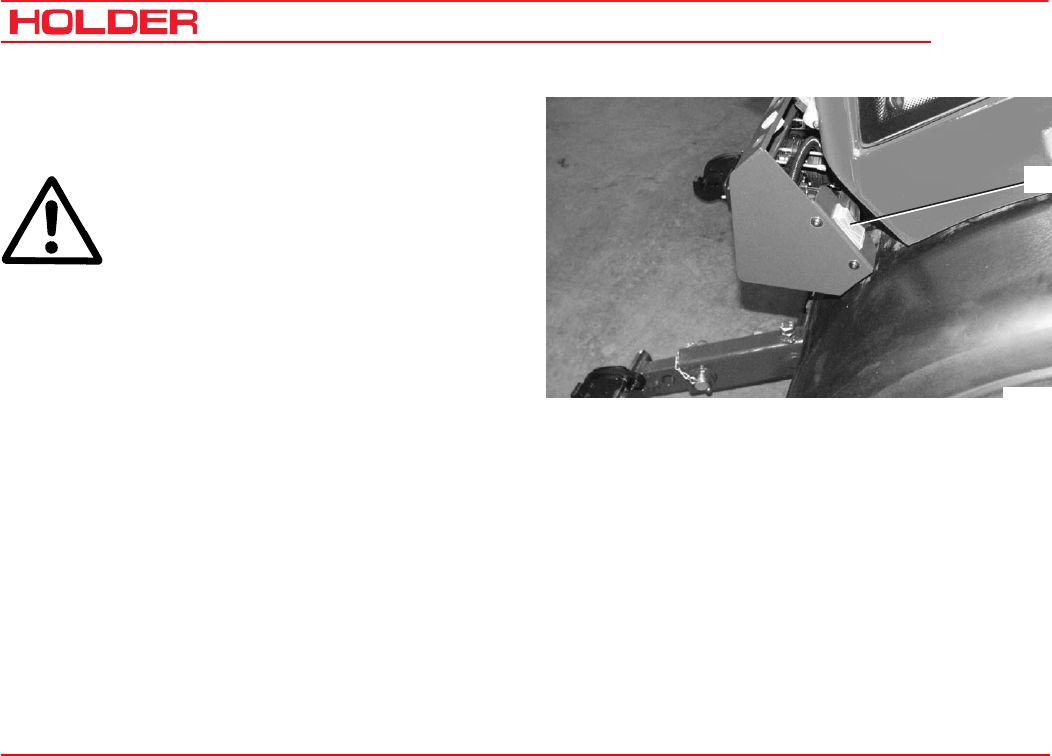
C 4.74
Operating instructions
92 149 443
Operating the implements
1
Bild_C181
External operation of the front power lift
The front power lift can be operated from outside the cab.
ATTENTION
When leaving the cab, set the forward/reverse
selector switch to neutral and apply the park-
ing brake to secure the vehicle against roll-
ing.
- To raise the front power lift push toggle switch (1) up.
The front power lift will be raised as long as the toggle switch
is depressed.
- To lower the front power lift push toggle switch (1)
down.
The front power lift will be lowered as long as the toggle
switch is pushed.

Operating instructions
149 443 93
C 4.74 Operating the implements
3
5
4
21
Bild_C212
Flow limiter for joystick
1 Button for individual flow limitation for each individual
joystick function.
- Turn on the main switch for working hydraulics.
The lifting and lowering speed of the power lift can be stored
individually with the flow limitation.
- Operate the joystick (4) until the desired cylinder
speed is reached, then press button (1).
This value is stored as the maximum speed and it applies
for the full stroke of the joystick.
If the full oil flow is required again, proceed as follows:
- Move the joystick (4) as far as possible and press
button (1).
The full oil flow is released for the full stroke of the joystick.
Toggle button for Float Position Button
2 Button for setting the joystick button (3) to “float
position of front power lift“
- Press the button (2).
The button (3) is now also activated as float position button
for the front power lift.
Its activation is indicated with two flashing LEDs.
NOTE
You can also toggle the float position on and off
with button (3).
Its activation is indicated with the LED (5).
- Press the button (2) again to toggle the switch.
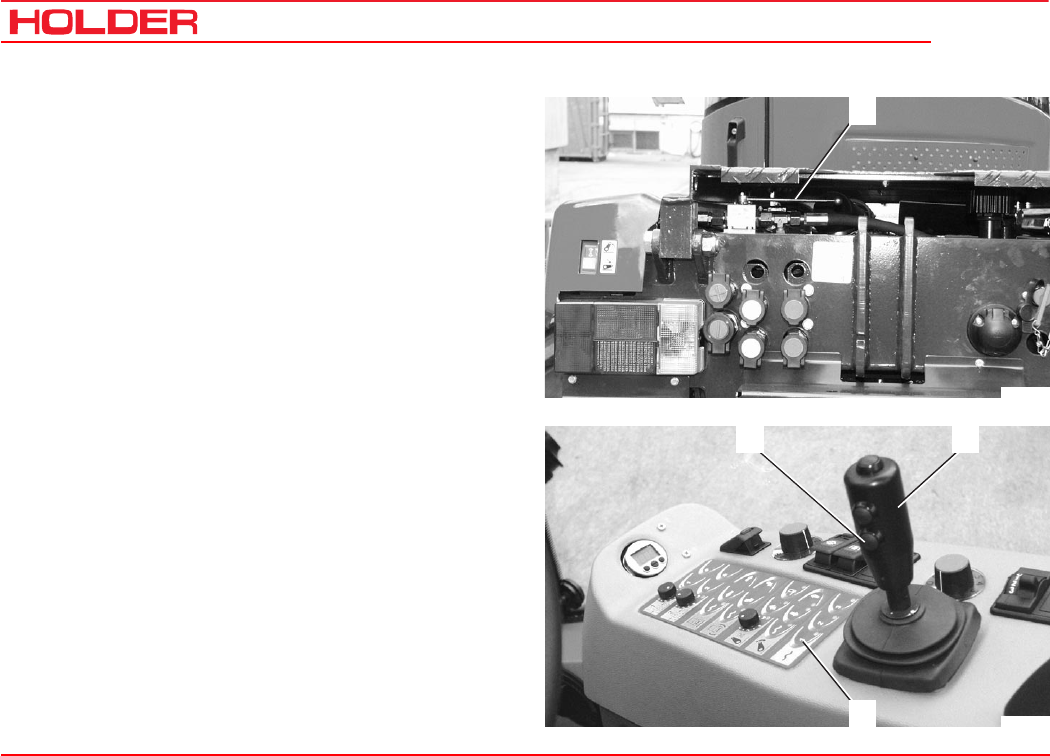
C 4.74
Operating instructions
94 149 443
Operating the implements
3
4
2
Bild_C213
1
Bild_C277
Operating the rear power lift*
The following movements are possible:
Turn on the main switch (5) for working hydraulics.
- Set the switch lever (1) at the rear to the position
„Rear Power Lift“.
- To raise the lift, press button (2) and pull the joystick
(3) back.
• The rear power lift (implement) will be raised.
You can stop the movement by releasing the joystick.
- Press button (2) and push the joystick (3) forward.
• The rear power lift (implement) will be lowered.
The float position is turned on with the keyboard.
- To turn it on, press button (4). The red LED comes
on.
• The float position of the rear power lift is turned
on, ie the implement can be moved by external
force.
- Press button (4) to turn it off. The red LED will go off.
* Option
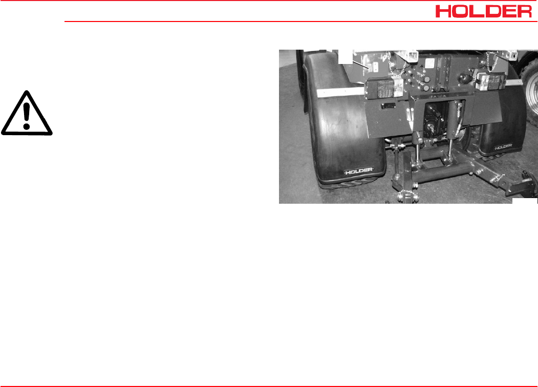
Operating instructions
149 443 95
C 4.74 Operating the implements
1
Bild_C271
External operation of the rear power lift*
The rear power lift can be operated from outside the cab.
ATTENTION
When leaving the cab, set the forward/reverse
selector switch to neutral and apply the park-
ing brake to secure the vehicle against roll-
ing.
- To raise the rear power lift push toggle switch (1) up.
The rear power lift will be raised as long as the toggle switch
is depressed.
- To lower the rear power lift push toggle switch (1)
down.
The rear power lift will be lowered as long as the toggle
switch is depressed.
* Option
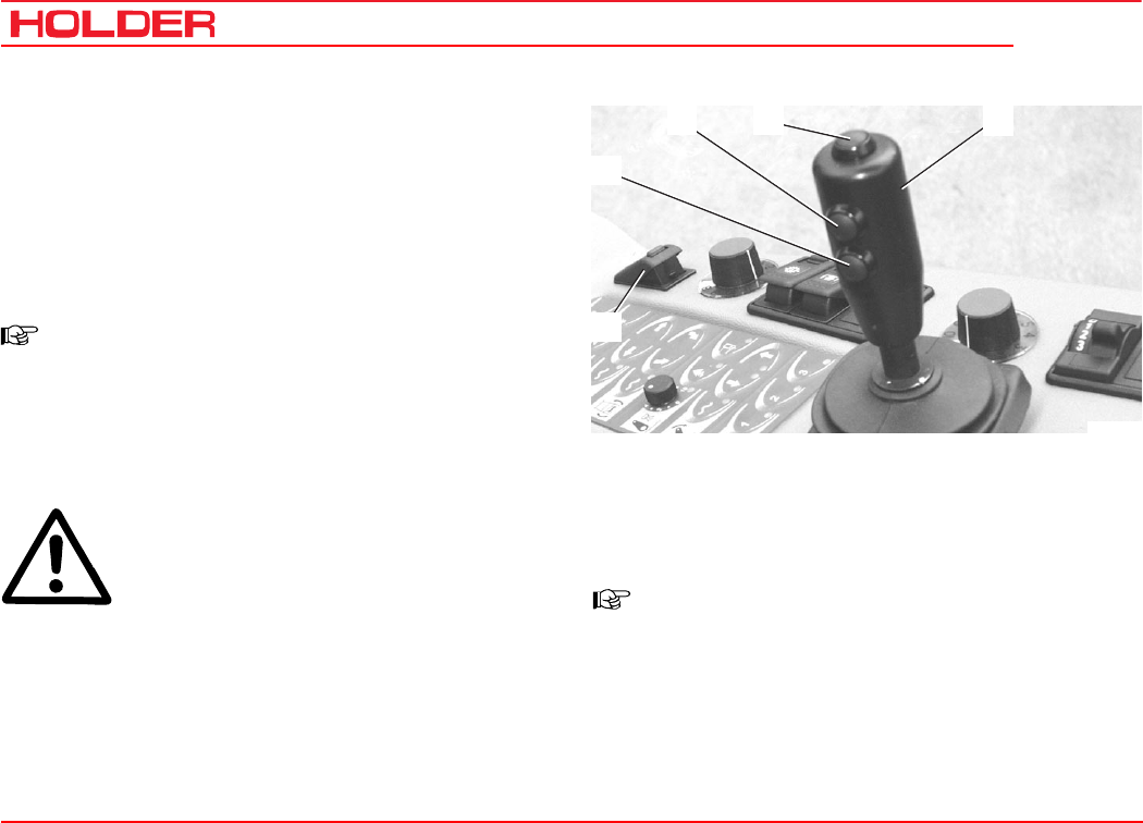
C 4.74
Operating instructions
96 149 443
Operating the implements
4
32
5
1
Bild_C176
Operating the hydraulic couplings
1 Pushbutton 1 for joystick level 1
2 Pushbutton 2 for joystick level 2
3 Pushbutton 3 for joystick level 3
4 Joystick (joystick level 0 without pushbutton opera-
tion)
5 Main switch for working hydraulic system
NOTE
The joystick controls those functions of the
implements which are connected to the front
or rear hydraulic couplings. The couplings and
notice plates for the joystick are colour coded,
ie the colours and the function are matched.
DANGER
Due to the variety of implements and con-
nections, however, we recommend a trial run
of the movement at a safe place without dan-
ger to persons or risk of material damage
before starting operation.
The function of the joystick can only be carried out if the
main switch (5) is turned on.
NOTE
The joystick can be operated forward and
back as well as to the right and left: The func-
tions are shown on the notice plate.
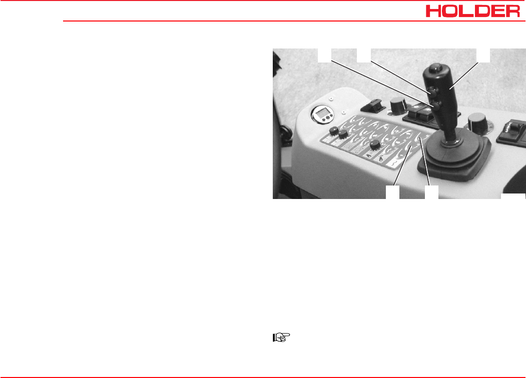
Operating instructions
149 443 97
C 4.74 Operating the implements
4
67
2
1
Bild_C215
Operating the green hydraulic couplings*
- Push the joystick (4) to the left or right.
• The green front right hydraulic couplings will be
supplied with oil.
You can stop the movement by releasing the joystick.
The float position is turned on with the keyboard.
- To turn it on, press button (7). The red LED comes
on.
• The float position of the green hydraulic couplings
is turned on, ie the implement can be moved by
external force.
- Press button (7) to turn it off. The red LED will go off.
Operating the blue hydraulic couplings*
- Press button (1) and move the joystick (4) to the left
or right.
• The blue front right hydraulic couplings
will be supplied with oil.
You can stop the movement by releasing the joystick.
The float position is turned on with the keyboard.
- To turn it on, press button (6). The red LED comes
on.
- Press button (6) to turn it off. The red LED will go off.
Operating the yellow and white hydraulic couplings*
- Press button (2) and move the joystick (4) to the left
or right.
• The yellow rear left hydraulic couplings
will be supplied with oil.
- Press button (2) and move the joystick (4) to the left
or right.
• The white front right hydraulic couplings will be
supplied with oil.
NOTE
The yellow and white hydraulic couplings do not
have a float position.
* Option
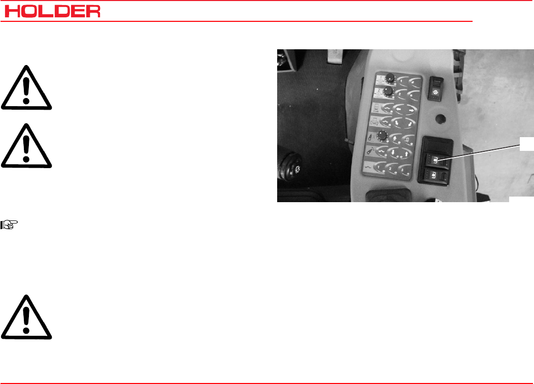
C 4.74
Operating instructions
98 149 443
Operating the implements
1
Bild_C182
Turning on the front PTO
DANGER
Before turning on the PTO, make sure no-
one is standing close enough to the vehicle
and the driven implement to be hurt.
ATTENTION
Check the mounting angle of the cardan shaft.
Do not start it under 1500 rpm.
- Release the lock at the starting safety switch (1) and
depress the switch. The front PTO is turned on.
- To turn it off, depress the safety switch at the top.
NOTE
If the engine temperature is too high, the PTO
will turn off automatically and an alarm will
sound. The engine must cool at idle speed
before being turned off. Restart the engine
after checking for the cause.
DANGER
After the installed implement is turned off, it
can continue to run. Wait until the implement
is stationary before working on it again.
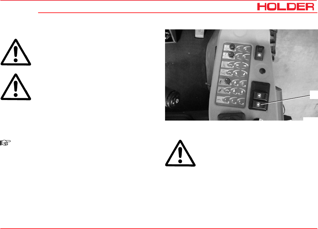
Operating instructions
149 443 99
C 4.74 Operating the implements
Turning on the rear PTO*
DANGER
Before turning on the PTO, make sure no-
one is standing close enough to the vehicle
and the driven implement to be hurt.
ATTENTION
Check the mounting angle of the cardan shaft.
Do not start it under 1500 rpm.
- Release the lock at the safety switch (1) and depress
the switch. The rear PTO is turned on.
- To turn it off, depress the safety switch at the top.
NOTE
If the engine temperature is too high, the PTO
will turn off automatically and an alarm will
sound. The engine must cool at idle speed
before being turned off. Restart the engine af-
ter checking for the cause.
DANGER
After the installed implement is turned off, it
can continue to run. Wait until the implement
is stationary before working on it again.
1
Bild_C183
* Option
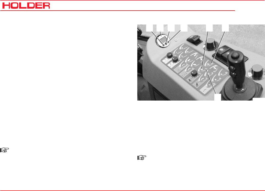
C 4.74
Operating instructions
100 149 443
Operating the implements
65
7
431 2
Bild_C188
Operating the hydraulic cushioning* (front power lift)
The hydraulic cushioning allows the ground pressure of the
implement to be decreased steplessly and to increase the
front axle loading. This improves the climbing ability. When
driving on roads with a lifted implement, the hydraulic sys-
tem will absorb shocks caused by bumps in the road.
- Press button (5). LED (7) will come on.
The electronic pressure sensor (2) with a digital display al-
ways indicates the current pressure of the front power lift
when float position is turned off.
- Press the mode button (3).
- S.P.1 will appear in the display and after 2 seconds
the current setting will start to blink.
- You can change the setting with the decrementing
button (1) or incrementing button (4), until the ground
pressure of the device is reduced as desired.
- The value S.P.1 must be less than the pressure with
a raised implement.
NOTE
After 3 seconds without a button being
pressed, the display reverts and the settings
are stored.
Adjusting the hysteresis
- Press the mode button (3) twice within 3 seconds.
- HYS.1 will appear in the display and after 2 seconds
the current setting will start to blink.
- You can change the setting with the decrementing
button (1) or incrementing button (4). It should be
between 5 and 10 bar.
NOTE
The gas pressure in the diaphragm accumu-
lator is 30 bar.
* Option
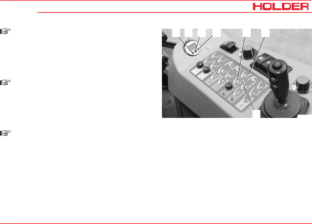
Operating instructions
149 443 101
C 4.74 Operating the implements
65
7
431 2
Bild_C188
NOTE
A cushioning pressure of less than 30 bar
(light implements) will result in too many con-
trol operations as the accumulator can not
act.
Driving on-road with implement cushioning
NOTE
Do not raise the implement completely and
switch the front power lift to single-acting
(LED (6) must be illuminated) for the cush-
ioning to take effect.
Operation with implement cushioning
NOTE
If the implement adapts to uneven ground with
delay, reduce the cushioning pressure or
HYS.1.
- Turn the implement cushioning off for light imple-
ments (eg rotary mower).
Turning the implement cushioning off
- Press button (5), select float position or operate the
joystick. The LED (7) goes off.
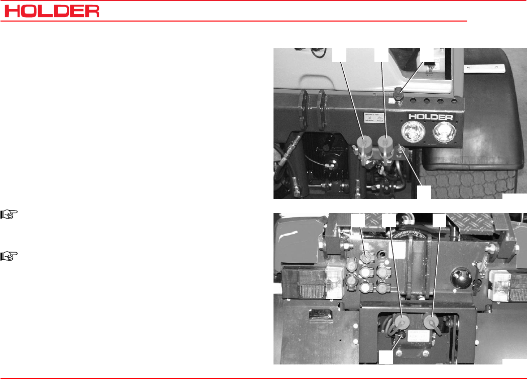
C 4.74
Operating instructions
102 149 443
Operating the implements
4
3
1 2
Bild_C279
13
4
2
Bild_C280
Operating the variable pump for implements* (setting
from - 0 - 100 litres)
The variable pump for the implements is a devices for driv-
ing implements with a high hydraulic power demand such
as a spiral-bladed lawn mower. It is operated electrically
from the driver’s station.
- Connect the hydraulic hoses of the front or rear
implement to the quick couplings (1) for return flow
and (2) for boost pressure and, if required, to the
black leakage oil coupling (3).
- Insert the implement encoded plug into the socket (4)
next to the quick couplings.
NOTE
Only one implement coded plug may be in-
serted at the front or rear.
NOTE
If a new or unknown implement is to be in-
stalled, the wiring harness for implement cod-
ing 204-80-72 must be used. The correct cod-
ing must be established in consultation with
the implement manufacturer and Holder.
* Option
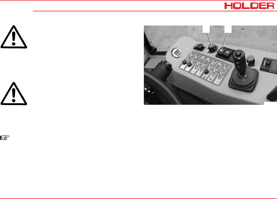
Operating instructions
149 443 103
C 4.74 Operating the implements
6
5
Bild_C185
ATTENTION
Turn on the starting safety switch (6) only at
low engine speed.
- Set the rotary knob (5) to 0.
- Release the lock at the starting safety switch (6) and
depress the switch. The indicator in the switch comes
on.
ATTENTION
After the speed of the motor was raised, the
oil flow may only be raised slowly.
- Turn the rotary knob (5) for adjusting the oil flow from
0 to 100 litres/min until the performance of the imple-
ment is reached.
NOTE
The implement coded plug specifies the maxi-
mum oil flow for the related implement (for
safety reasons).
The number 11 on the ring corresponds to the maxi-
mum oil flow specified by the coding.
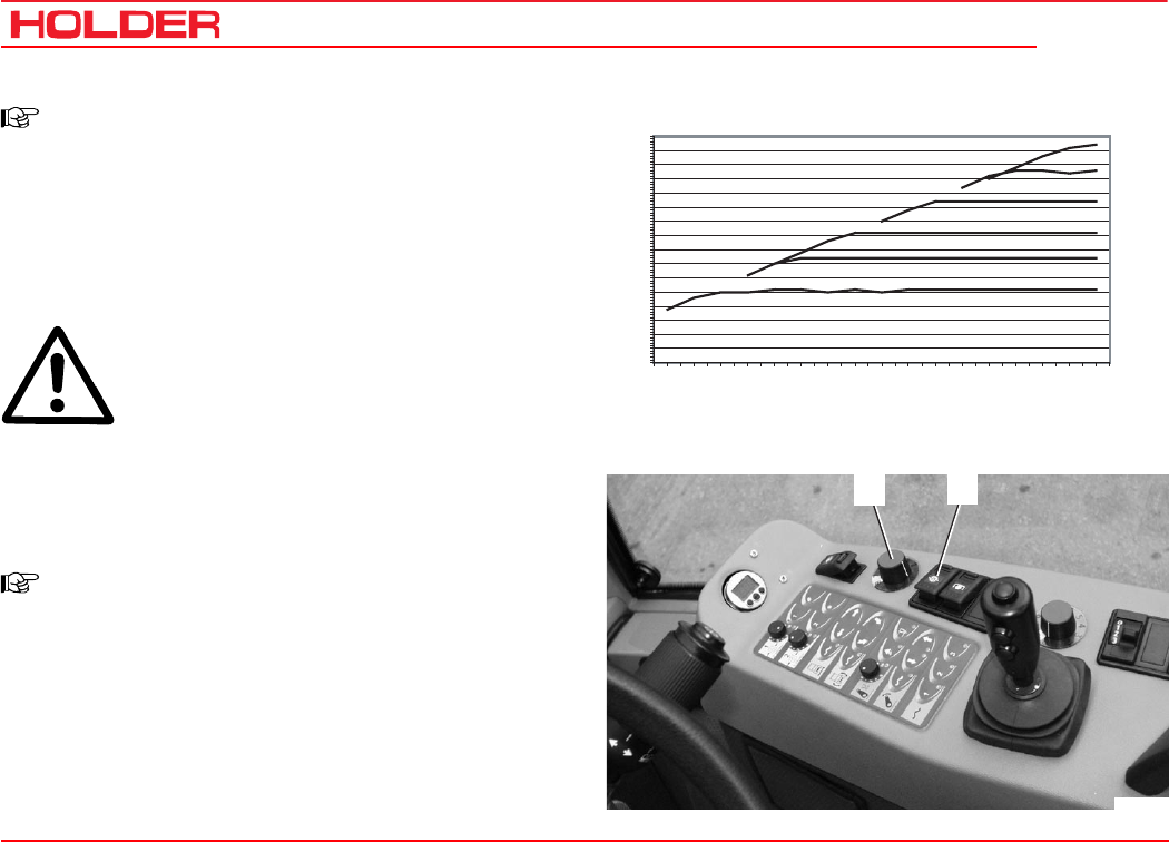
C 4.74
Operating instructions
104 149 443
Operating the implements
6
5
Bild_C185
C4.74 Variable-displacement pump
0
20
30
40
45
50
55
60
65
70
75
80
85
90
95
100
105
1100
1200
1300
1400
1500
1600
1700
1800
1900
2000
2100
2200
2300
2400
2500
2600
2650
Engine RPM [1/min]
Displacement [
litres
]
50 litres
60 litres
70 litres
80 litres
90 litres
100 litre
s
Bild_C278_GB
NOTE
The implement variable-displacement pump
attempts to maintain the oil flow specified by
the coded plug and potentiometer, even when
the engine speed is reduced.
The oil flow is only reduced at lower rpm when
the maximum swash angle of the pump is
reached (see diagram).
ATTENTION
If the implement is not in use, turn the pump
off with the safety switch to prevent any un-
necessary overheating of the hydraulic oil.
Turning off the implement variable-displacement
pump
- Turn the safety switch (6) off. The indicator in the
switch extinguishes.
NOTE
If you shut down the engine without first turn-
ing off the implement variable-displacement
pump, the pump can not immediately be
turned on again on for safety reasons.
Before a new start you must first either:
- set the rotary knob to 0, or
- turn the safety switch off and on again once,
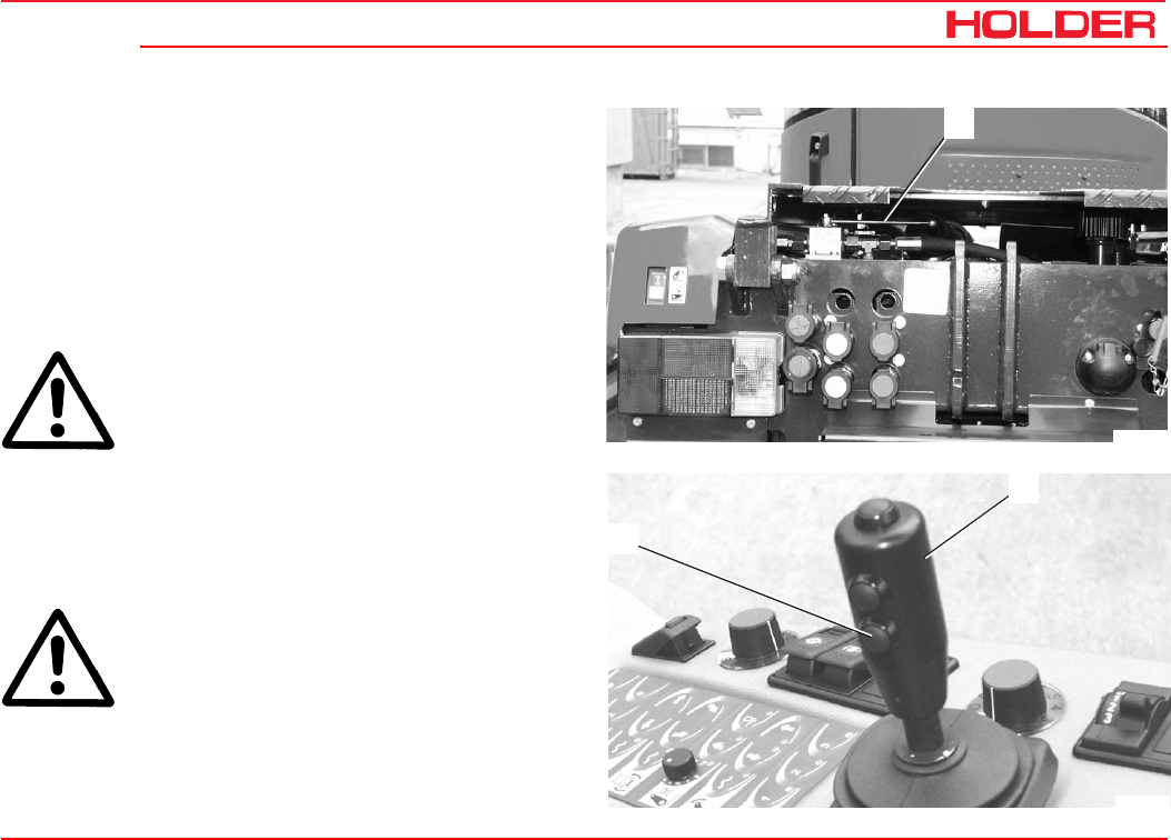
Operating instructions
149 443 105
C 4.74 Operating the implements
3
2
Bild_C187
1
Bild_C277
Operating the hydraulic dumper
With the hydraulic dumper it is possible to lift the dump
body fast and easily. The dumper tilts loading platform* to
the rear.
- Start the engine.
Switch lever for device to be operated:
- Put the switch lever(1) at the rear to the “dumper“
position (side position).
DANGER
Make sure no-one is standing in the danger
zone at the rear.
- Press button (2) and pull the joystick (3) back.
• The dumper will be raised. To stop dumping,
release the joystick.
- To lower it, press button (2) and push the joystick (3)
forward.
DANGER
Make sure no-one is standing in the danger
zone at the rear - danger of being crushed.
The dumper will be lowered.
* Option
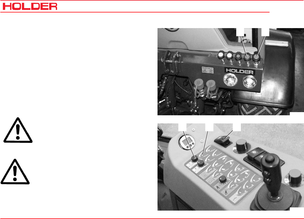
C 4.74
Operating instructions
106 149 443
Operating the implements
21
Bild_C189
53 4
Bild_C190
Operating priority flow valve I*
Priority flow valve I is used to drive the servo motor in an
implement with a variable hydraulic power demand, for ex-
ample, salt spreader, hedge cutter, etc. The working speed
can be set independently of the vehicle engine speed. The
priority flow valve is supplied by the (standard) working pump
and operated from the driver’s station.
- Connect the hydraulic hoses of the implement to the
red quick couplings for the drive (1) and return line (2)
at the front of the vehicle.
- Turn on the main switch (5) for working hydraulics.
ATTENTION
Press button (4) only at low engine speed.
- Press button (4). The red LED will come on.
ATTENTION
Slowly increase the speed of the engine.
* Option
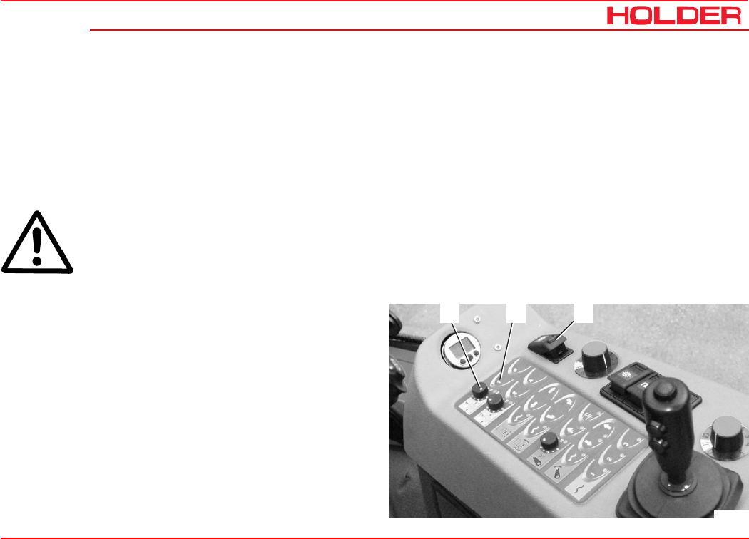
Operating instructions
149 443 107
C 4.74 Operating the implements
53 4
Bild_C190
- Select the desired engine speed with the hand throt-
tle.
- Set the rotary knob (3) to the operating speed required
for the implement.
Turning clockwise increases, turning counterclock-
wise lowers the speed.
- The servo motor in the implement is supplied with an
oil flow of 0 to 25 litres/min.
ATTENTION
If the implement is not in use, always turn
the priority flow valve off with button (4) to
prevent any unnecessary overheating of the
hydraulic oil.
Do not leave the priority flow valve on:
- If the engine is running and no load is connected to
the couplings
- or is not in operation,
- when driving without needing oil
The overheating can damage the hydraulic system.
Turning off the priority flow valve
- Press button (4). The red LED red will extinguish.
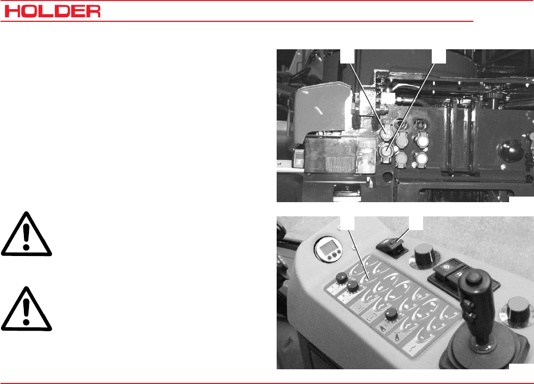
C 4.74
Operating instructions
108 149 443
Operating the implements
21
Bild_C191
43
Bild_C192
Operating priority flow valve II*
Priority flow valve II is used to drive the servo motor in an
implement with a variable hydraulic power demand, for ex-
ample, salt spreader, hedge cutter, etc. The working speed
can be set independently of the vehicle engine speed. The
priority flow valve is fed by the tandem working pump and
set at the rear of the vehicle.
- Connect the hydraulic hoses of the implement to the
red quick couplings for the drive (1) and return line (2)
at the rear of the vehicle.
- Turn on the main switch (4) for working hydraulics.
ATTENTION
Press button (3) only at low engine speed.
- Press button (3). The red LED will come on.
ATTENTION
Slowly increase the speed of the engine.
* Option
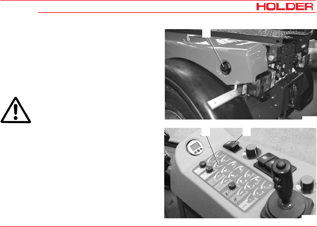
Operating instructions
149 443 109
C 4.74 Operating the implements
5
Bild_C193
43
Bild_C192
- Select the desired engine speed with the hand throt-
tle.
- Go to the rear of the vehicle and adjust the hand
wheel (5) of the priority flow valve to the working
speed required for the implement.
Turning clockwise increases, turning counterclock-
wise lowers the speed.
- The servo motor in the implement is supplied with an
oil flow of 0 to 25 litres/min.
ATTENTION
If the implement is not in use, always turn
the priority flow valve off with button (3) to
prevent any unnecessary overheating of the
hydraulic oil.
Do not leave the priority flow valve on:
- If the engine is running and no load is connected to
the couplings
- or it is not in operation
- when driving without needing oil
The overheating can damage the hydraulic system.
Turning off the priority flow valve
- Press button (3). The red LED red will extinguish.
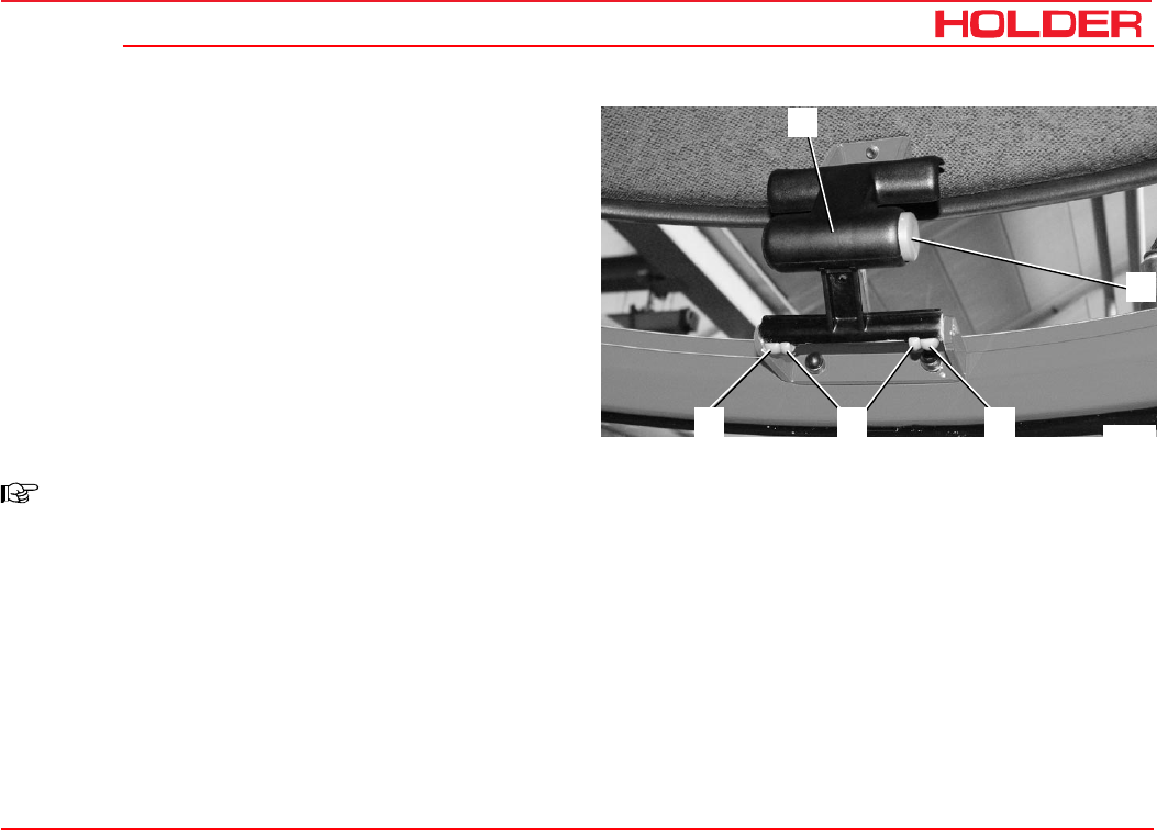
149 443 111
C 4.74 Operating instructions
43 3
2
1
Bild_C194
Other activities
Operating the driver’s cab
Operating the roof hatch
Opening the roof hatch
- Press the button (2) on the side of the handle.
- Push the handle (1) up to open the roof hatch at the
rear.
Removing the roof hatch
NOTE
The roof hatch can be used as an emergency
exit in case of danger.
- Open the roof hatch.
- Press out the inner plastic clip (4) to the back.
- Press the outer plastic clip (3) inward.
- Push the hatch up with the handle (1).
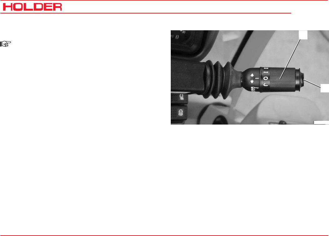
C 4.74
Operating instructions
112 149 443
Other activities
2
1
Bild_C195
Turning on windshield wiper/washer
NOTE
The vehicle is provided with a front wiper. A
washer system is also installed. The washer
system draws its water from the washing
water reservoir at the front left-hand side in
the cabin.
Front windshield wiper/washer
- Turn the rotary switch (1) for the front windshield
wiper to stage J.
The front windshield wiper is turned on to intermittent
operation.
- Turn the rotary switch (1) to stage I.
The windshield wiper is turned on to slow continuous
operation.
- Turn the rotary switch (1) to stage II.
The windshield wiper is turned on to quick continuous
operation.
- Press button (2) on the lever.
The front windshield washer is on and sprays only as
long as the button is pressed.
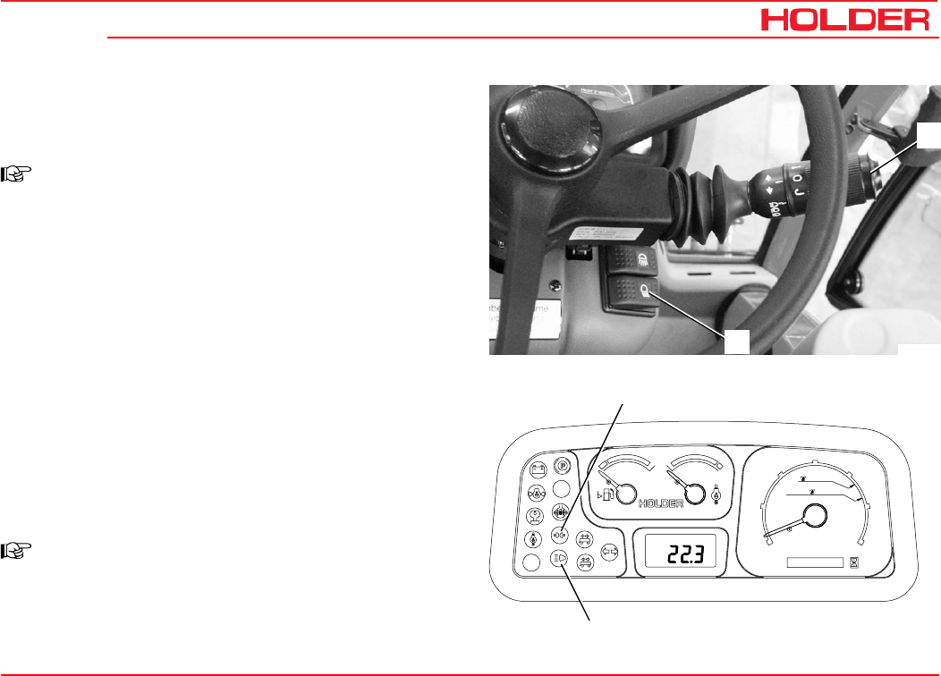
Operating instructions
149 443 113
C 4.74 Other activities
2
1
Bild_C196
Km/h
0000000 h
25
15
FRONT
540U/min
1000U/min
20
5
10
30
RPMx100
PTO
electronic
0
Motor
digital system
1
2
3
4Bild_C197
Lights
Turning on and operating the lights
NOTE
Turn the preheat/starter switch to position 1.
- Set the light switch (2) to position 1.
The front clearance lights (3,6) and the tail lights
(10,14) (parking light) are switched on.
- The clearance light indicator (3) in the multifunctional
display will come on.
- Set the light switch (2) to position 2.
The front headlights (1, 8) (dip beam) are turned on.
Turning on high beam
- Set the light switch (2) to position 2.
- Move the turn signal lever (1) down. The headlights
(2, 7) are set to high beam.
- The high beam indicator (4) in the multifunctional
display will come on.
NOTE
To use the headlight flasher, pull the turn sig-
nal lever up.
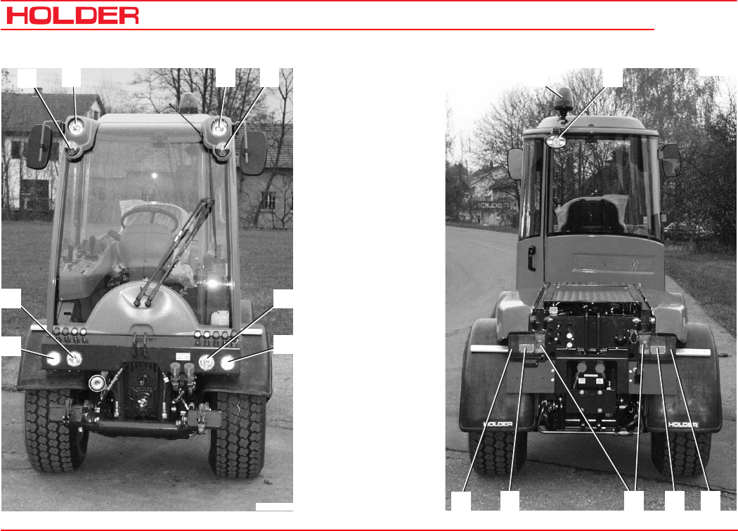
C 4.74
Operating instructions
114 149 443
Other activities
Bild_C220
1
2
34 5 6
8
7
Bild_C221
11 12
15141310
9
1 Right headlight,
dip beam
2 Right headlight,
high beam
3 Turn signal and
clearance light, right
4 Headlight, top
5 Headlight, top
6 Turn signal and
clearance light, left
7 Left headlight,
high beam
8 Left headlight,
dip beam
9 Stop light
10 Tail light
Turn signal light, left
11 Rotating beacon
mount
12 Flood light*
13 Reversing light
14 Tail light
Turn signal light,
right
15 Stop light
* Option
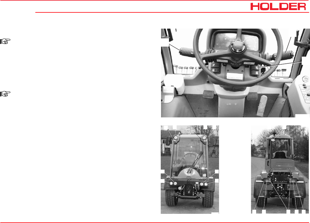
Operating instructions
149 443 115
C 4.74 Other activities
3
2
1
Bild_C198
Bild_C220
1
2
34 5 6
8
7
Bild_C221
11 12
15141310
9
Turning on the top headlights
NOTE
If front implements are installed and the bot-
tom headlights are hidden, you may turn on
the upper headlights.
- Turn on the toggle switch for the top headlights (2).
- The top headlights (4, 5) will go on.
NOTE
The high beam and headlight flasher func-
tions are only available for the bottom head
lights.
Signalling to the left, signalling to the right
- Move the turn signal lever (1) back to turn the left turn
signal lights (6, 10) on.
- The turn signal indicator in the multifunctional display
will come on.
- Move the turn signal lever (1) forward to turn the right
turn signal lights (3, 14) on.
Operating the horn
- Press turn signal lever (3) in to sound the horn.
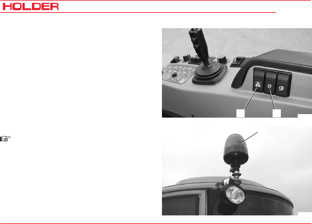
C 4.74
Operating instructions
116 149 443
Other activities
1 2
Bild_C199
3
Bild_C200
Operating the hazard warning flasher system
- Turn on the hazard warning flasher switch (1) to let all
the turn signal lights flash.
Turning on the rotating beacon*
NOTE
The rotating beacon may only be turned on if
the vehicle is used for applications in public
traffic areas.
- Turn the rotating beacon switch (2) on.
The rotating beacon (3) will be on.
* Option
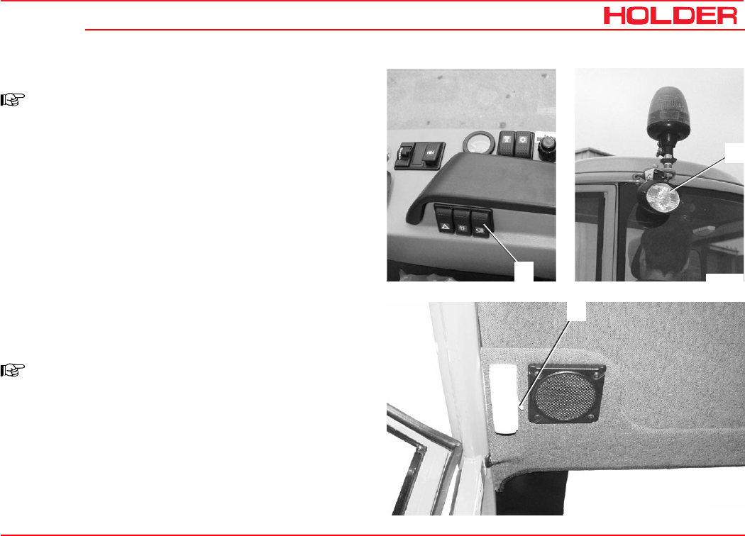
Operating instructions
149 443 117
C 4.74 Other activities
Bild_C201
1
2
1
Bild_C202
Turning on the flood light*
NOTE
The flood light must not be used in the public
traffic area.
- Turn the flood light switch (1) on.
The flood light (2) will be on.
Interior light
Turning on the interior light
NOTE
There is an interior light on the left and right
in the cabin roof.
- To turn on the interior lights, operate the light switch
(1).
* Option
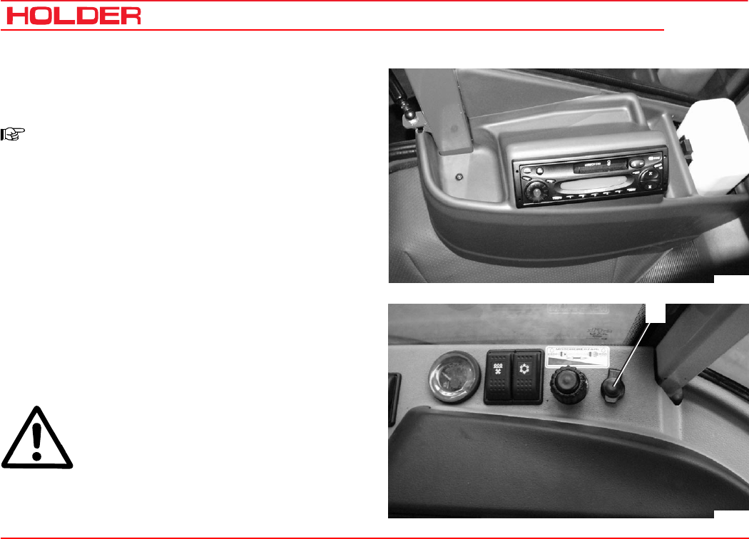
C 4.74
Operating instructions
118 149 443
Other activities
3
Bild_C203
Bild_C283
Radio* and loudspeakers*
Operating the radio
NOTE
There is a separate operating manual for the
radio.
Please observe the instructions in this manual for operation
of the radio.
The loudspeakers are installed at the front in the roof of the
cabin.
Power socket
Connecting equipment to the power socket
- You can connect
12 VDC equipment with a maximum power rating of
15 A to the power socket (3) with a commercial
automotive plug.
ATTENTION
Do not leave any equipment running unat-
tended; if the engine is not running the bat-
tery can be discharged.
* Option
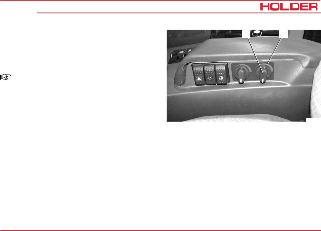
Operating instructions
149 443 119
C 4.74 Other activities
2
1
Bild_C272
Heater
Heating and ventilating
Turning on the heater
NOTE
The cabin heater is heated by the engine
cooling oil.
- To heat the cabin, turn the rotary knob (1) clockwise.
You may select any intermediate position. Turn the
knob CCW to reduce the heating capacity, CW to
increase it. See the label (2) behind the rotary knob.
- To turn the heater off, turn rotary knob (1) CCW.
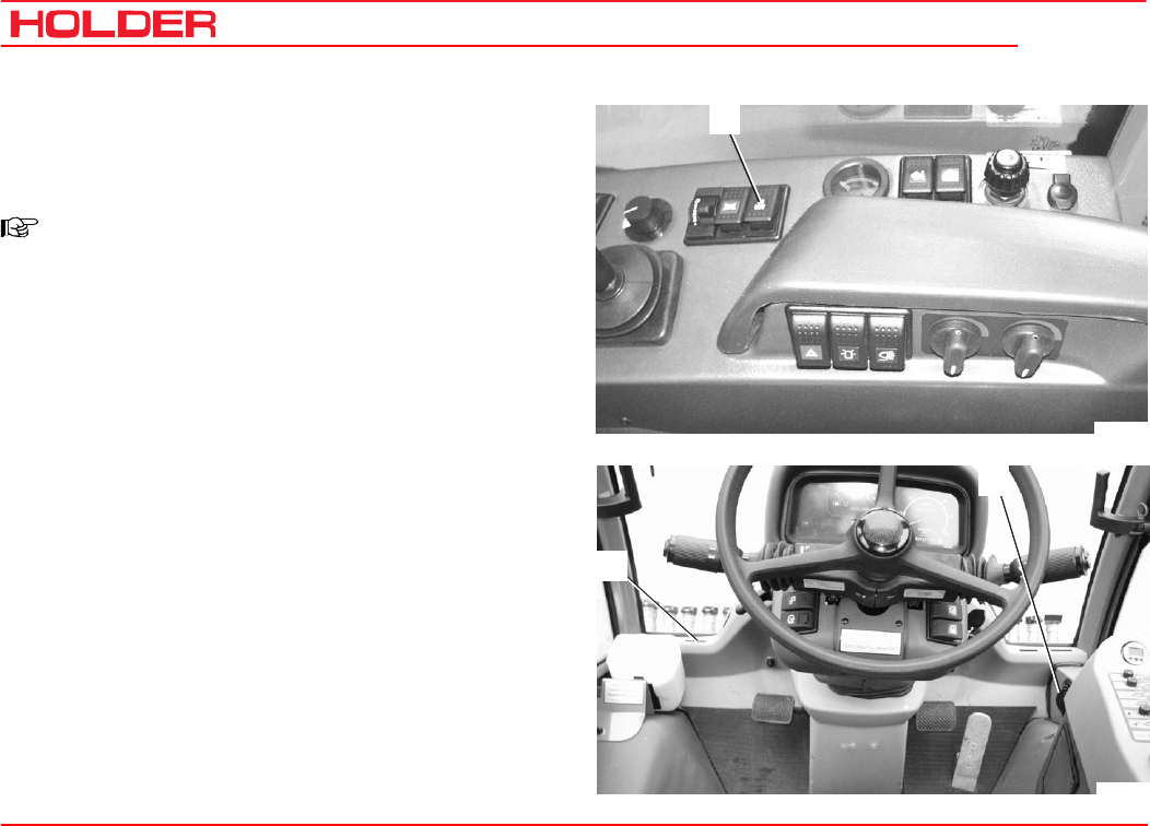
C 4.74
Operating instructions
120 149 443
Other activities
5
4
Bild_C205
3
Bild_C281
Turning on the ventilation
- To ventilate the cabin turn on the fresh air blower
switch (3).
NOTE
The fresh air blower has 2 speeds.
- Position 1 slow
- Position 2 fast
There are several air vent nozzles (4, 5) fitted in the cabin:
- 1 adjustable nozzle (4) at the bottom front right in the
foot room
- 13 air slots (5) in the dash for front and side windows
- 1 nozzle for circulating air supply to the right of the
driver’s seat
- Set the air vent nozzles to the desired direction and
desired air flow.
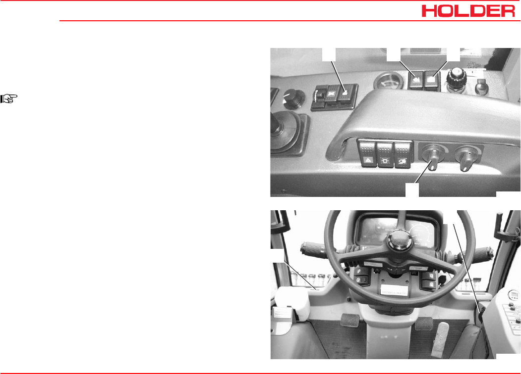
Operating instructions
149 443 121
C 4.74 Other activities
32
1
4
Bild_C284
5
6
Bild_C285
Air conditioning
Operating the air conditioning*
NOTE
A separate operating manual is supplied for
the air conditioning.
Please observe the instructions in this manual
for operation of the A/C.
Air conditioning*
1 Switch for 2-speed blower
2 Blower reversing switch
3 On/off switch
4 Temperature control
5 Air slots
6 Adjustable air vent nozzle
- Set the air vent nozzles to the desired direction and
desired air flow.
Cleaning the condenser
- Turn on the ignition (engine off).
- Operate the blower reversing switch (2).
- The blower will run in the opposite direction as long as
the switch is operated.
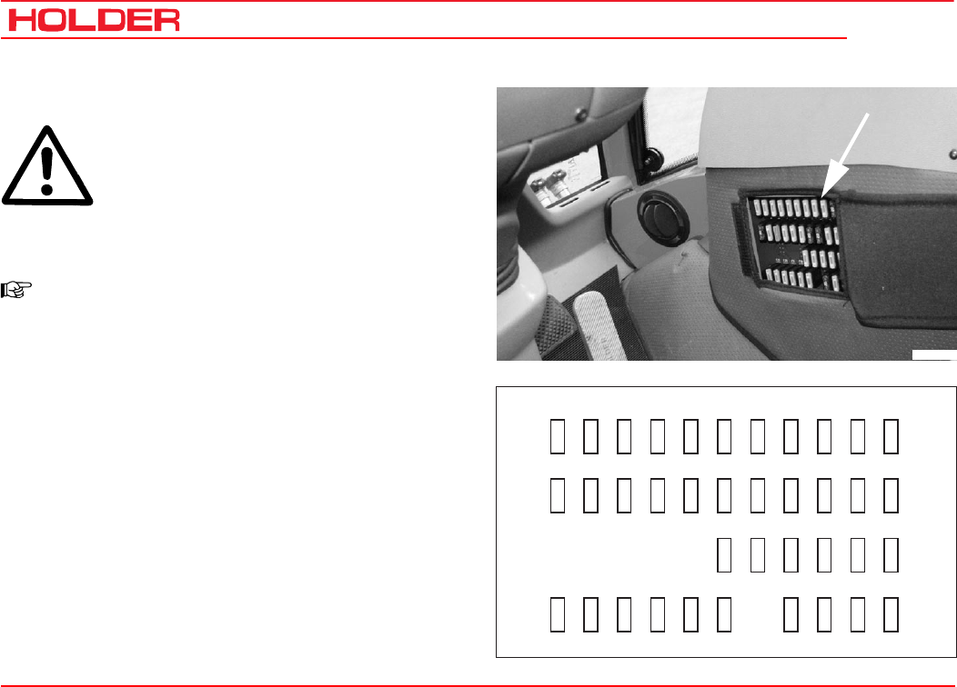
C 4.74
Operating instructions
122 149 443
Other activities
Bild_C206
15 A
F01
20 A
F12
15 A
F29
15 A
F02
15 A
F13
15 A
F30
15 A
F03
15 A
F14
15 A
F31
15 A
F04
15 A
F15
15 A
F32
15 A
F05
15 A
F16
15 A
F33
15 A
F06
15 A
F17
15 A
F23
15 A
F34
15 A
F07
20 A
F18
15 A
F24
15 A
F08
20 A
F19
15 A
F25
20 A
F35
15 A
F09
15 A
F20
15 A
F26
15 A
F36
20 A
F10
15 A
F21
15 A
F27
1 A
F37
15 A
F11
15 A
F22
15 A
F28
1 A
F38
Bild_C207
Fuses
CAUTION
Before carrying out any work on the electri-
cal equipment, for example, replacing the
fuses, always turn the battery isolating switch
off.
Vehicle fuses
NOTE
The fuses for the vehicle are installed below
the console at the right-hand side. Open the
flap for access.
F01 Multifunctional display, remote thermometer,
hydraulic system
F02 Inductive speed switch/rear 3-pin connector socket
F03 Rotating beacon
F04 Parking light, rear 58R
F05 Lighting for multifunctional display/hydr. remote
thermometer/hazard warning switch
F06 Parking light, left 58L/rear number plate light
F07 Headlight, high beam/high beam indicator light
F08 Headlight, low beam
F09 Intermittent front wiper
F10 Warning light

Operating instructions
149 443 123
C 4.74 Other activities
15 A
F01
20 A
F12
15 A
F29
15 A
F02
15 A
F13
15 A
F30
15 A
F03
15 A
F14
15 A
F31
15 A
F04
15 A
F15
15 A
F32
15 A
F05
15 A
F16
15 A
F33
15 A
F06
15 A
F17
15 A
F23
15 A
F34
15 A
F07
20 A
F18
15 A
F24
15 A
F08
20 A
F19
15 A
F25
20 A
F35
15 A
F09
15 A
F20
15 A
F26
15 A
F36
20 A
F10
15 A
F21
15 A
F27
1 A
F37
15 A
F11
15 A
F22
15 A
F28
1 A
F38
Bild_C207
F11 Radio 30/interior light
F12 Air conditioner
F13 2-pin socket/electric seat adjuster 15
F14 Heatable external mirrors
F15 Stop light
F16 Headlight flasher/0-position wiper/washer
F17 Cigarette lighter/rear cab flood light
F18 Deutz shutoff solenoid
F19 Cooling air blower/heater/A/C
F20 Spare
F21 Radio 15
F22 Turn signal light
F23 Spare
F24 Spare
F25 Seat heater
F26 Reversing pushbutton/pump coding
F27 Spare
F28 Spare
F29 Diff. lock/2-stage steering/parking brake solenoid
valve
F30 Solenoid valve, PTO, rear
F31 Solenoid valve, PTO, front
F32 Bucher hydraulic system pin 23 / supply on/off
switch
F33 Bucher electronics pin 05
F34 Bucher electronics pin 34
F35 Electronic traction control, Bosch RC 6-9 it. 1 and
27/back-up lights
F36 Horn/air cleaner maintenance switch
F37 Electronic traction control Bosch RC 6-9
it. 13,41,42
F38 Electronic traction control Bosch RC 6-9
it. 10,11,12,23,37,48 & 61/diagnosis socket/
forward/reverse selector switch/variable-displace-
ment pump control
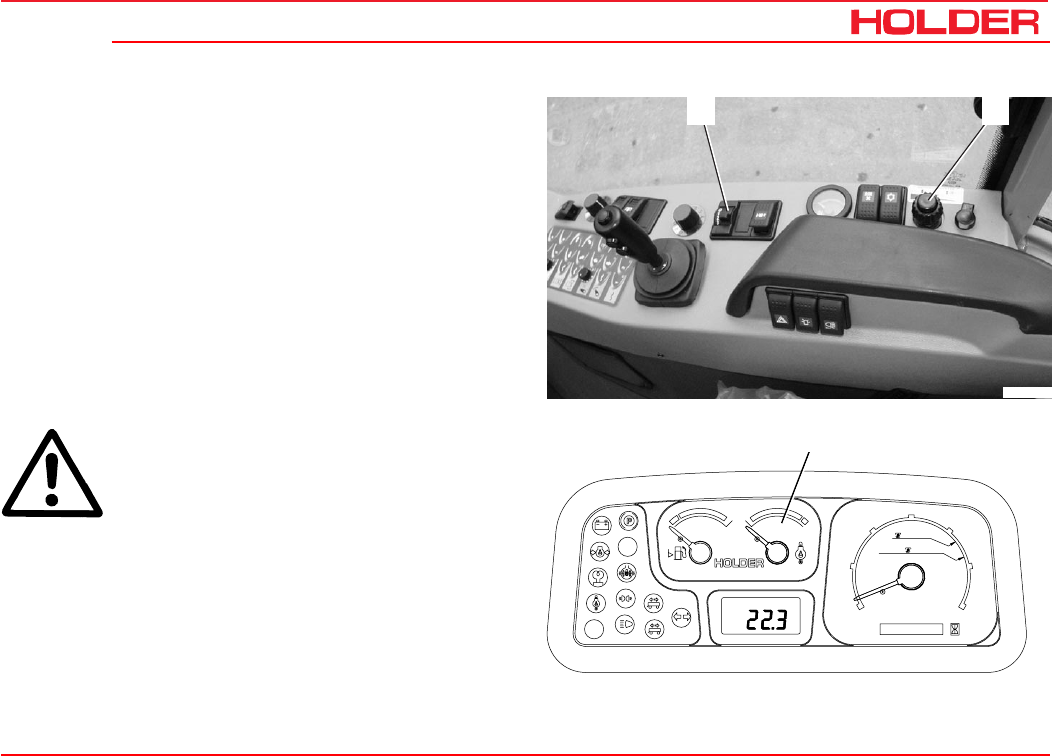
149 443 125
C 4.74 Operating instructions
21
Bild_C208
Km/h
0000000 h
25
15
FRONT
540U/min
1000U/min
20
5
10
30
RPMx100
PTO
electronic
0
Motor
digital system
1
2
3
Bild_C209
Taking out of operation
Leaving the vehicle
Stopping
- Lower the implement completely.
- Engage the parking brake.
- Fully push in the hand throttle button (2) (idle posi-
tion).
- Set the forward/reverse selector switch to 0.
- Set the driving program switch (1) to 0.
ATTENTION
If the engine is overheated (engine tempera-
ture gauge (3) in the red field), let the engine
run without a load until the temperature has
dropped to the green area. Do not let the en-
gine run unattended!
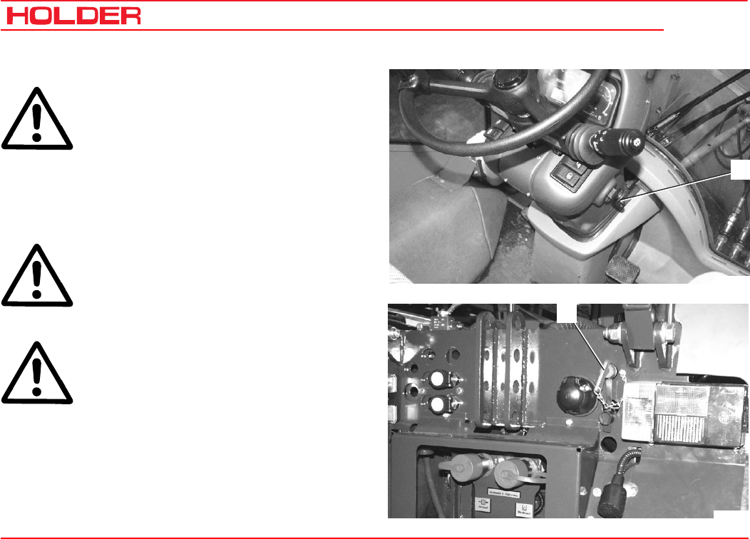
C 4.74
Operating instructions
126 149 443
Taking out of operation
3
Bild_C210
4
Bild_C211
Shutdown
ATTENTION
If the vehicle is parked on gradients, it must
be secured against rolling with chocks.
- If equipped with a hydrostatic drive, also use chocks
to secure the vehicle.
- Turn the ignition key (3) back to 0. The engine is shut
down.
- Remove the ignition key and take it with you.
CAUTION
Do not leave the cabin without taking the ig-
nition key.
- Turn off the battery isolating switch (4).
Emergency stop
In case of an emergency stop with a defec-
tive inching pedal or defective traction hy-
draulics, the vehicle can only be brought to a
halt by turning the ignition to 0 and applying
the service brake.
Leaving the vehicle
- Lock the cab door with the key.
- If necessary, secure the vehicle against rolling
with chocks.

149 443 127
C 4.74 Operating instructions
Trailers, towing
Your vehicle can tow the following trailers:
Table of trailers
The following trailer combinations are allowed:
1 Vehicle with single-axle trailer with brakes or without brakes.
2 Vehicle plus single-axle trailer with brake or without brake plus two-axle trailer with override brake.
3 Vehicle plus two-axle trailer with brake plus two-axle trailer with override brake.
4 Vehicle plus two trailers with override brakes, one single-axle trailer plus one two-axle trailer, or one two-axle trailer plus
one single-axle trailer.
NOTE
The total length of the vehicle-trailer train must not exceed 18 m.
Type of Trailer Permissible Total Weight Braking System
Single axle trailer 2.2 t No braking system
Single and multiple axle trailer Up to 2.2 tons
With own braking system if the trailer brake lever
can be mounted easily accessible beside the
driver's seat
Single axle tailer Up to 4.5 tons With overrunning brake
Multiple axle trailer Up to 4.5 tons With service brake system and parking and rapid-
emergency brake
Trailer Up to 6 tons With hydraulic or pneumatic braking system
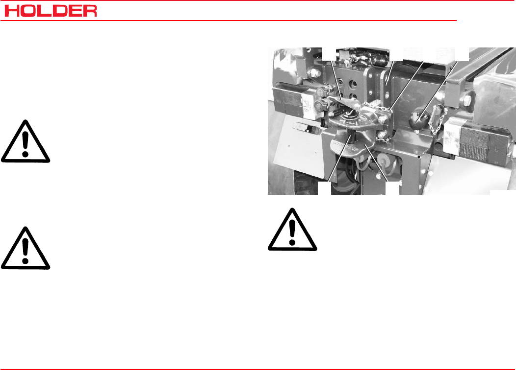
C 4.74
Operating instructions
128 149 443
Trailers, towing
Bild_C269
12 43
5
6
Operating the trailer hitch manually, attaching trailers
- Put the trailer hitch (5) in the two lower holes provided
on the adjustment rail (2) with the fastening pin (3)
and secure the pins with the retaining clips.
Bearing load
ATTENTION
The bearing load must be at least 25 kg (4 % of
the trailer load), while the maximum bearing load
must not exceed 600 kg.
If the bearing load is underrun or exceeded when
unloading the trailer, the load must be shifted
so that the bearing load returns to the permis-
sible range.
- Drive the vehicle in front of the trailer to be attached.
DANGER
The trailer must be secured against uninten-
tional movement (rolling).
- Push the safety (1) down and pull the tow pin (6) out
of the hitch (5).
DANGER
Make sure no-one is standing between the
vehicle and trailer.
- Drive the vehicle with the coupler head into the trailer
tongue.
- Reinsert the tow pin and lock it.
- Connect the trailer lighting to the connector socket (4).
- Remove the wheel chocks from the trailers.
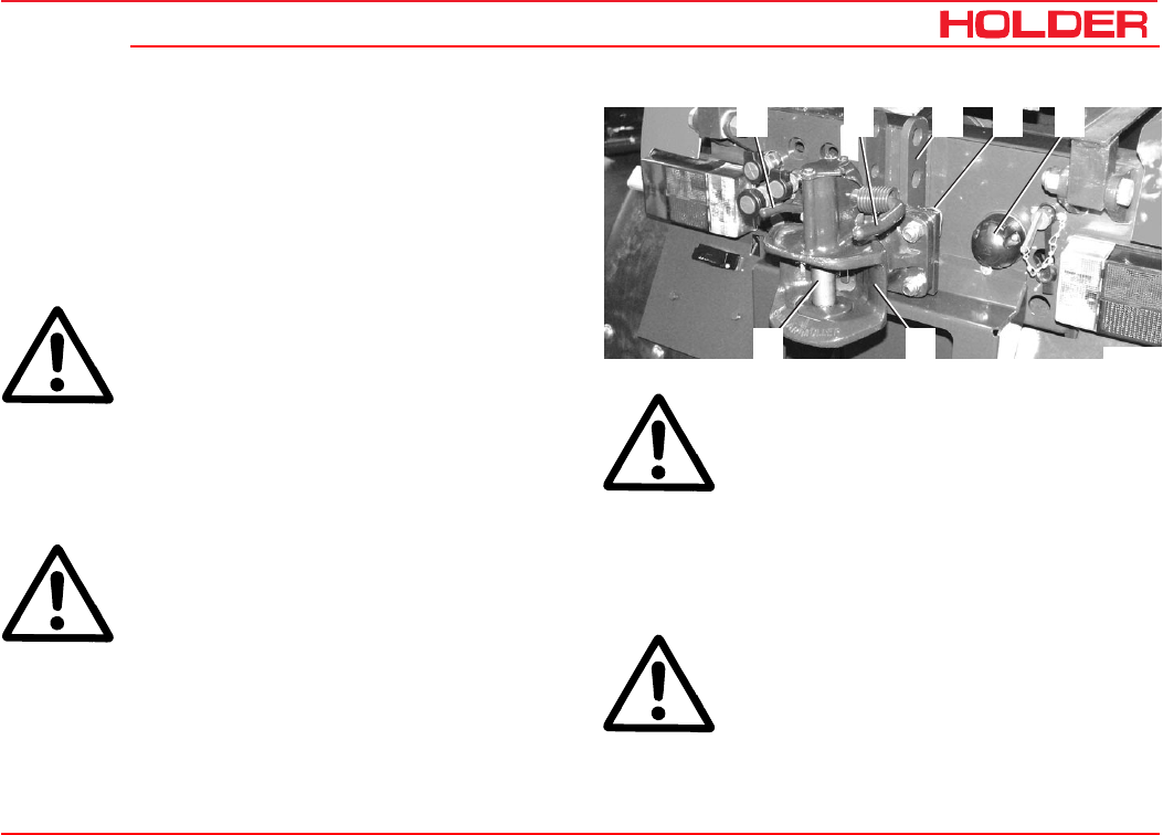
Operating instructions
149 443 129
C 4.74 Trailers, towing
Bild_C270
1 2 3 54
6
7
Operating the trailer hitch automatically, attaching
trailers
- Put the trailer hitch (6) in the two lower holes provided
on the adjusting rail (3) with the fastening pin (4) and
secure the pins with the retaining clips.
Bearing load
ATTENTION: The bearing load must be at least
25 kg (4 % of the trailer load), while the maxi-
mum bearing load must not exceed 600 kg. If
the bearing load is underrun or exceeded when
unloading the trailer, the load must be shifted
so that the bearing load returns to the permis-
sible range.
- Drive the vehicle in front of the trailer to be attached.
DANGER: The trailer must be secured against
unintentional movement (rolling).
- Pull the release lever (2) up until the tow pin (7) opens
the coupler head.
DANGER
Make sure no-one is standing between the
vehicle and trailer.
- Drive the vehicle with the coupler head into the trailer
tongue. The hitch will close on contact, the tow pin (7)
goes through the eye of the tongue. The hitch can
also be closed by pressing the lever (1).
DANGER
The trailer hitch must be completely closed.
- Connect the trailer lighting to the connector socket (5).
- Remove the wheel chocks from the trailers.
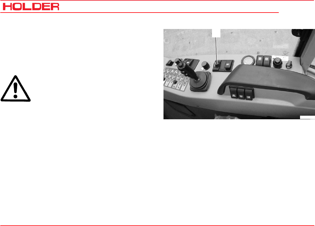
C 4.74
Operating instructions
130 149 443
Trailers, towing
1
Bild_C217
Driving with trailers
- Turn the driving program switch (1) to range 1 or 2.
The maximum drawbar pull is achieved in range 2.
- Drive the vehicle as described in the section on
driving.
DANGER
If a trailer not requiring a permit is attached,
the driving speed is limited to 25 km/h. The
trailer must be identified with a 25 km/h sign.
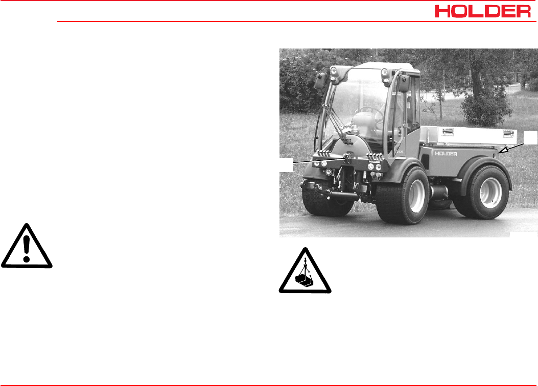
149 443 131
C 4.74 Operating instructions
1
2
Bild_C222
Transport, hoisting, towing
Instructions for transport
- Drive the vehicle on the hauling vehicle.
- Shut down the vehicle as described in section “Leav-
ing the Vehicle“.
- Secure the vehicle against rolling with chocks at the
wheels and, if needed, with wood blocks at the sides
to prevent it from sliding.
- Tie the vehicle down at the front to the upper link
support (1), at the rear to the trailer hitch (2).
Hoisting instructions
DANGER
When hoisting the vehicle, only use lifting
equipment and a crane with a sufficient load
capacity.
- The hoisting weight must not exceed the permissible
total weight:
The hoisting weight is given on the vehicle identification plate
and in the tables of weights in the technical data.
- Hoist the vehicle only with the lifting equipment
attached to all 4 wheels.
DANGER
Do not step or stand under a suspended load.
Danger!
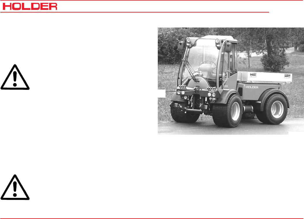
C 4.74
Operating instructions
132 149 443
Transport, hoisting, towing
1
Bild_C223
Towing instructions
Your vehicle can be towed if disabled due to damage. Use
the upper link support at the front at the driver’s cab for
towing.
DANGER
The towing vehicle must have sufficient trac-
tive and braking force for the towed load with-
out brakes.
- The towed load must not exceed the permissible total
weight.
The total weight of the vehicle is given on the identifi-
cation plate and in the tables of weights in the techni-
cal data.
- Attach the towing device (in case of failure of the brake
only a rigid tow bar) to the upper link support (1).
- Set the forward/reverse selector lever to the centre
position (no direction of travel selected).
- Let the engine run so that the power steering is in
operation.
CAUTION
If the engine is not running during towing or
the hydraulic system has failed, steering is
difficult. Increased effort is required for steer-
ing in this case.
- Have the vehicle towed to the nearest workshop at a
maximum of 10 km/h.
- Park the vehicle secured against rolling.
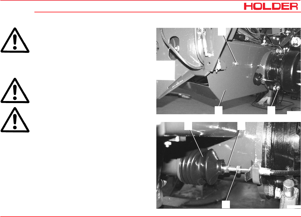
Operating instructions
149 443 133
C 4.74 Transport, hoisting, towing
ATTENTION
If the parking brake can not be released due
to a lack of pressure in the accumulator and
pressure can not be built up on account of a
failure of the engine or hydraulic system, re-
move the brake cable on the hydraulic cylin-
der so that the vehicle can be towed.
DANGER
Secure the vehicle against rolling with chocks.
CAUTION
The brake cable is very taut - risk of injury.
- Remove the bolts (1) on the left and right side of the
protective hull.
- Remove the protective hull (2).
- Remove the boot (3) on the right and push it back.
- Loosen the locknut (4).
- Fully remove the setscrew (5).
The parking brake may only be restored by an authorized
workshop.
1
12
Bild_C286
3 4
5
Bild_C287

149 443 135
C 4.74 Operating instructions
Indicators, adjustments
Adjusting the speedometer
The adjustment of the speedometer in the multifunctional
display is required when changing from large to smaller tires
and vice versa.
Please refer to the maintenance instructions for the adjust-
ment of the speedometer.

149 443 137
C 4.74 Operating instructions
Troubleshooting guide
The following tables list problems and their possible causes.
If you can not carry out the remedy yourself, please con-
tact an authorized workshop or our customer service.
Test and Control Box BB3 or the Bodem PC software, with
which further troubleshooting/diagnostics are possible, are
available as an option.
Problems in engine and exhaust gas turbo-
charger
Please observe the notices in the operating instructions for
the engine.
Problem Cause Remedy
Traction electronics - general Faults in the traction electronics
Warning light is on or flashes if the
following conditions are met:
• Ignition on
• Driving program switch on 1,2,3 or
4
• Forward/reverse selector switch in
neutral
Read out fault history with BB3 or
Bodem
Eliminate faults
Clear faults in the fault history
Problems in electronic and hydraulic driving
systems

C 4.74
Operating instructions
138 149 443
Troubleshooting guide
Problem Cause Remedy
Low tractive force Fault in boost or high-pressure system Check suction filter in return line
Check boost pressure in hydraulic system
Check high-pressure hydraulic system
Check for leaks on variable-
displacement pumps and wheel motors
Check control units and proportional
solenoids of variable-displacement
pumps
Check maximum current at
proportional solenoids
Eliminate detected faults
No forward and reverse travel Drive of variable-displacement pumps
defective
Forward/reverse selector switch in
neutral
Machine started with preselected
direction of travel
No power supplied to the electronics
Electrical connection to the variable
pump interrupted
Repair
Put forward/reverse selector switch
in desired direction of travel
Put forward/reverse selector switch
in neutral and preselect desired
direction of travel
Check fuses
Check electric connection
Make connection

Operating instructions
149 443 139
C 4.74 Troubleshooting guide
Problem Cause Remedy
No forward and reverse travel Forward/reverse selector switch
defective or bad contact
Drive program switch at 0
Replace forward/reverse selector
switch, make contact
Select desired driving program
No forward and reverse travel or only
one direction Fault in boost or high pressure system Check boost pressure in hydraulic
system
Check high-pressure hydraulic
system
Check control units and proportional
solenoids of variable-displacement
pumps
Eliminate detected faults
No fast-slow available Driving program switch defective
Hydraulic valve for slow/fast defective
or no pressure available
Electric connection to hydraulic valve
for slow/fast interrupted or bad contact
Renew driving program switch
Check hydraulic valve
Make connection
Vehicle drives in one direction only Forward/reverse selector switch
defective
Electrical connection to the variable-
displacement pump interrupted
Replace forward/reverse selector
switch
Make connection

C 4.74
Operating instructions
140 149 443
Troubleshooting guide
Cause Remedy
No maximum speed Diesel engine does not attain
maximum speed
Inching pedal not at maximum speed
Variable-displacement pump not at full
delivery
Check throttle linkage
Check diesel engine
Adjust inching pot, calibrate
Check maximum current, check
proportional solenoid valve
Does not remain stationary with
inching pedal depressed Inching pedal at wrong position,
maybe foreign objects in the control
Inching pot not adjusted properly
Adjust properly, remove any foreign
objects
Adjust inching pot, calibrate
Inching pedal not functioning
(warning light flashes) Inching pot defective or no contact
Electronic unit faulty
Replace inching pot, calibrate
Repair cable connector
Renew electronic unit
Machine does not stop without
depressing accelerator in driving
program 1 or 2
Engine idle speed too high
Incorrect calibration
Check engine, adjust idling speed,
check actuator
Carry out calibration

Operating instructions
149 443 141
C 4.74 Troubleshooting guide
Problem Cause Remedy
Differential lock does not operate Fuse blown or bad contact
Switch defective
Hydraulic valve for differential lock
defective or no pressure exists
No power
Differential lock on wheel motor too
hard to operate
Check fuse,
remake contact
Check / renew the switch
Check hydraulic system and
hydraulic valve
Check and repair electrical
connections, cables
Repair
Parking brake can not be released Switch defective
Too little pressure in accumulator
Check / replace switch
Start engine to build up pressure

C 4.74
Operating instructions
142 149 443
Troubleshooting guide
Problems in the hydraulic system and steer-
ing
NOTE
These notes only apply for valve arrange-
ments conforming to our circuit diagrams or
approved by Bucher Hydraulics.
Problem Cause Remedy
Power lift or hydraulic cylinders not
lifting. No pressure build-up noticeable
(steering working normally).
Slide valve in input plate stuck due
to foreign objects.
Remove and clean slide valve in
input plate LU8SSCS-
OM22/04!
Do not change pressure setting!
Power lift lifting with too little power. Pressure setting too low
Oil level too low.
Reset pressure with pressure gauge
(190 bar).
Fill up specified type of oil
Operating pressure is only reached
with high RPM
Pump defective Replace pump
Power lift not lifting
Not enough power
Drops after operation.
Lift cylinder leaky
Valve leaky
Clean / replace

Operating instructions
149 443 143
C 4.74 Troubleshooting guide
Problem Cause Remedy
Hydraulic oil heats too quickly, system
works against excess pressure.
(engine under load)
Cylinder at limit stop
Implement not connected but
joystick in work position (quick
coupling)
Put joystick in neutral position
(free circulation)
Put joystick in neutral position
(free circulation)
Hydraulic oil foams Leaks in suction area Check all pipe connections and
tighten, if required
Hydraulic system working too slowly,
accompanied by whistling noise Hydraulic oil level too low
Temperatures too low
Fill up as specified
Fill proper type of oil as specified in
maintenance instructions
Steering not working Proportional valve dirty
Relief valve in hydraulic steering not
closing
Clean proportional valve (installed
on right side of body)
Remove and clean (authorized
workshop)
Lost steering motion when steering
direction is changed rapidly Leaks in steering return line Check hose couplings for leaks

C 4.74
Operating instructions
144 149 443
Troubleshooting guide
Problems in the working hydraulic system
The diagnostic unit OPUS and PC software are available
as options with which further troubleshooting/diagnosis/ad-
justment of the electronics in the working hydraulic system
is possible.
NOTE
These notes only apply for valve arrange-
ments conforming to our circuit diagrams or
approved by Bucher Hydraulics.
Problem Cause Remedy
All hydraulic functions not active Control unit (box) without power
Connector or cable set defective
Control unit defective,
watch flashing code of LED on box
Turn on main switch (toggle switch)
Repair or replace connectors, cables
Replace
Individual functions not active Function disabled
Connectors or cables damaged
Solenoid or valve defective
Enable with Opus or PC software, also
see operating instructions.
Repair or replace
Repair or replace

Operating instructions
149 443 145
C 4.74 Troubleshooting guide
Problem Cause Remedy
Joystick inoperative Joystick disabled
Buttons defective
Enable with Opus or PC software
Determine defect with Opus, send
joystick in for repair or replace, also
see the operating instructions.
“Remote control troubleshooting”
Keyboard inoperative Mechanical or electric defect Determine defect with Opus or PC
software, replace keyboard and/or
related p. c. board
Many joystick and keyboard functions
malfunctioning simultaneously
Power supply cut off
(3 separate positive cables, pins 05,
23, 34
Determine and eliminate defect (cable
break, contact problems in connector).
Attention: Despite applied voltage in
off-state, power can fail during
operation
Functions too slow or too fast Flow limitation out of adjustment
Power value for certain channel too
low
Reset with “#” button and joystick or
Opus or PC software
Using Opus or PC software set in
“Channels” area from 800 to 1900 mA
4th control level on the joystick
malfunctioning
Activated with special function of “*”
button
Press “*” button again
Joystick or keyboard malfunction Bus line defective (Opus not
showing connection)
Ensure connection or replace cable

C 4.74
Operating instructions
146 149 443
Troubleshooting guide
Problem Cause Remedy
Many malfunctions Some parameters out of adjustment Load “default settings” with Opus or
PC software
Buttons respond too slowly Set incorrectly to “slow” Can be set to “fast” with Opus or PC
software
Buttons “locked” instead of “active” Set incorrectly Can be set with Opus or PC software
Hydraulic implement cushioning
inoperative
Turned off
Electronic pressure sensor defective
Specified pressure too low
Function switched to rear power lift
Turn on with keyboard
Replace
Change on electric pressure sensor
Set to “Front” with Opus
Implement cushioning pulsing a lot Specified pressure and hysteresis
too low or too high
Implement weight too low
Hydraulic pressure accumulator
defective, no cushioning noticeable
Change pressure sensor settings
Turning off the implement cushioning
Renew pressure accumulator
Position control inoperative Actual value transmitter (angle
sensor) defective
Angle sensor adjusted incorrectly
Angle sensor with incorrect range
setting
Renew
Readjust acc. to specifications
Increase higher value with specified
value potentiometer, decrease lower
value

Operating instructions
149 443 147
C 4.74 Troubleshooting guide
Problem Cause Remedy
Position control not always working Potentiometer ranges shifted
Actuator for angle sensor out of
adjustment
New calibration with Opus
Readjust and recalibrate angle sensor
Directional control valve leaky Foreign particles in seat valve Remove, clean or replace valve
cartridge
No pressure build-up Slide valve in input plate stuck
(foreign particles) Remove, clean slide valve or replace
plate
Strong oil flow fluctuation in flow
divider I or oil flow too low Lack of oil Higher RPM, reduce demand of 2nd
load
Troubleshooting is also possible with Opus or the PC soft-
ware in the menu
•Keyboard Check: Keyboard buttons.
•Output functions XO...Y3: Check if box provides
current for valves.
•Rear power lift position limiter: Functions of lift posi-
tion control.
•Cushioning device: Functions of hydraulic implement
cushioning
•Desired value channel.
•FCE1: Joystick functions.
•Diagnosis of master inputs.
•Diagnosis of BKN nodes.
Use the circuit diagrams and wiring diagrams.
Also refer to the Bucher Hydraulics operating instructions.

Operating instructions
149 443 149
C 4.74
General remarks on maintenance
To keep your vehicle always in peak condition, we would
ask you to study the information in these maintenance in-
structions very carefully. These chapters contain all the in-
formation you need for a conscientious treatment and care
of the vehicle. Place particular value on the performance of
the periodic maintenance.
Service
Please have all scheduled vehicle services (acc. to mainten-
ance schedule) and repairs carried out regularly by your
dealer (authorized workshop) and confirmed with a stamp
and signature in this manual.
Detach the double guarantee card, have it filled in by your
dealer and send it signed by the customer directly to:
Gebrüder Holder GmbH
P. O. Box 15 55
72545 Metzingen/Württ.
The warranty and product liability will only be maintained if
the maintenance services and inspections are carried out
regularly.
Qualification of service personnel
The vehicle, together with its attachments, may only be
used, serviced and repaired by persons who are familiar
with this equipment and have been warned of possible risks.
The qualified personnel entrusted with the work must have
the required tools.
The applicable safety regulations and rules must be ob-
served.
How to value the vehicle?
As you know, a car is judged by its age together with the
number of kilometres driven. The way to judge vehicles is
to consider their age together with the number of service
hours according to the following table:
Service hours Kilometres driven
150
10 500
150 7500
300 15000
600 30000
1500 75000

C 4.74
Operating instructions
150 149 443
General remarks on maintenance
Service
The following services were carried out:
In the maintenance table below you can enter the properly
carried-out services and inspections and have them con-
firmed.
(These entries are required to keep your warranty claims
intact):
Service
Interval
Hours of
Operation Date Signature
125
250
375
500
625
750
875
1000
1125
1250
1375
1500
Service
Interval
Hours of
Operation Date Signature
1625
1750
1875
2000
2125
2250
2375
2500
2625
2750
2875
3000

Operating instructions
149 443 151
C 4.74 General remarks on maintenance
Handling fuels and lubricants
• Fuels and oils must always be handled properly and as
specified by the manufacturer.
• Fuels and oils may only be stored in approved contain-
ers at specified places of storage. They can be inflam-
mable, therefore do not allow them to come in contact
with hot objects or with naked flames.
• Exercise caution when handling fuels - increased dan-
ger of fire. Do not fill any fuels in the vicinity of naked
flames, ignition sparks or hot engine parts. No smoking
when refuelling!
• Before refuelling, shut off the engine and remove the
ignition key. Do not refuel within enclosed spaces. Do
not spill fuels! (use suitable filling aids).
• Exercise caution when handling brake fluid and battery
acid (poisonous and corrosive).
• Only use clean vessels when filling fuel and oil.
• When using fuels, oils and cleaners, follow the safety
and disposal instructions of the manufacturer.
• Always avoid spilling. Eliminate spilled brake fluid
immediately with a suitable binding agent and discard
as specified by regulations.
• Oils, fuels, batteries, brake fluid and filters must be
disposed of separately and as specified by regulations.
• Before beginning lubrication, changing filter or opening
the hydraulic system, clean the area surrounding the
affected part carefully.
• Replaced parts must be discarded in a way friendly to
the environment.
• Observe all local and national laws and regulations.
CAUTION
The penetration of hydraulic oil under pres-
sure into the skin, eg through leaks, is dan-
gerous. If such injuries occur, seek medical
aid.
Safety notes for maintenance
Observe the notes in these maintenance instructions and
the general applicable safety and accident prevention rules!
• Do not allow anyone to stand around where they might
get hurt!
• When starting the engine, the traction and implement
drive must be shut off!
• Start the engine only from the driver’s station. Do not
start the engine by short circuiting the starter terminals,
as the machine could start moving immediately.

C 4.74
Operating instructions
152 149 443
General remarks on maintenance
• Do not run engine in enclosed spaces! Danger of
poisoning!
• To prevent the danger of fire, keep the vehicle and
implements clean!
• When leaving the vehicle, secure it against rolling and
unauthorized use (parking brake, chocks), stop the
engine, remove the ignition key and, if required, lock the
cabin!
• Never leave the vehicle unattended while the engine is
running!
• If external power loads are connected, eg equipment
with solenoid valves, protect them with diodes against
back currents. If not, the traction electronics could be
affected.
• Operate the equipment only if all guards are installed
and in position.
• Install and remove the articulated shaft only with the
engine stationary.
• When working with the PTO shaft, no-one should be
standing in the area of the rotating PTO and articulated
shaft.
• The guards for the articulated shaft and the PTO shaft
must be installed as specified.
• When the articulated shaft is removed, refit the protec-
tive cap on the PTO shaft.
• Do not perform any welding, cutting and grinding work
on carrying and other safety-relevant parts such as
vehicle frame, axles, trailer hitch, etc.
• When doing electric welding, disconnect all connector
plugs from the electronic units.
• The mounting of tires requires sufficient knowledge and
special mounting tools.
• Only use genuine HOLDER replacement parts! Use the
parts in the list of maintenance parts in the chapter
entitled “Maintenance data“.
• The vehicle and the implement must be checked for
road worthiness and operating safety before taking it
into operation and after servicing or repairs.
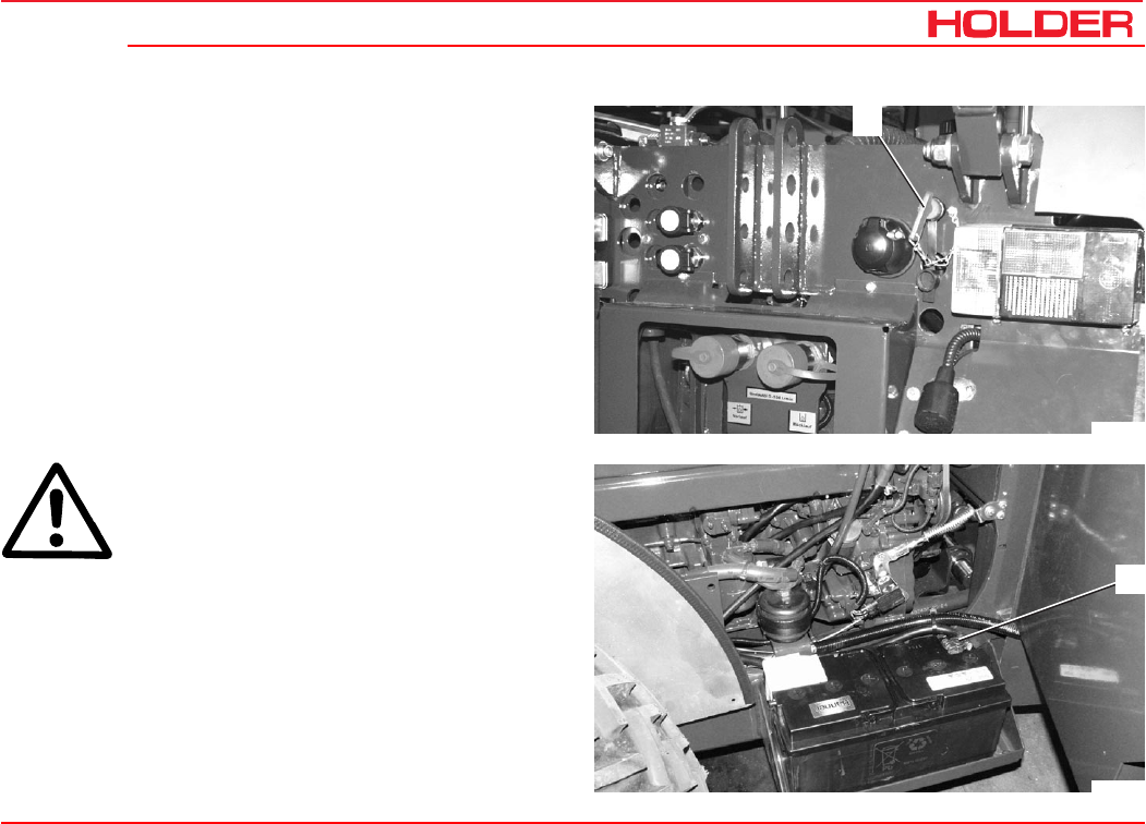
Operating instructions
149 443 153
C 4.74 General remarks on maintenance
1
Bild_C157
2
Bild_C235
Work on the electrical system
Before performing any services on the electrical equipment,
switch off power with the battery isolating switch (1).
- The switch must be horizontal, the toggle removed.
CAUTION
Disconnect the battery ground lead (2).
Do not place any metal parts on the battery terminals. Risk
of short circuit!
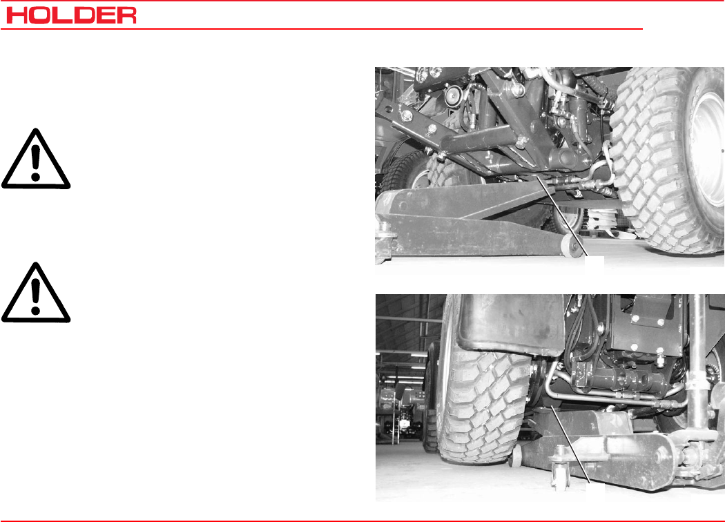
C 4.74
Operating instructions
154 149 443
General remarks on maintenance
1
Bild_C236
2
Bild_C237
Jack lift points
Jacking up
DANGER
When using the jack, be sure the vehicle is
shut down and secured against rolling
(chocks)!
The vehicle may only be jacked up at the shown locations
(1 and 2).
DANGER
The weight to be lifted should not exceed
the permissible load capacity of the jack.
When carrying out repairs, the raised vehicle must also be
secured against lowering with supports. Place the supports
under the axles on both sides.
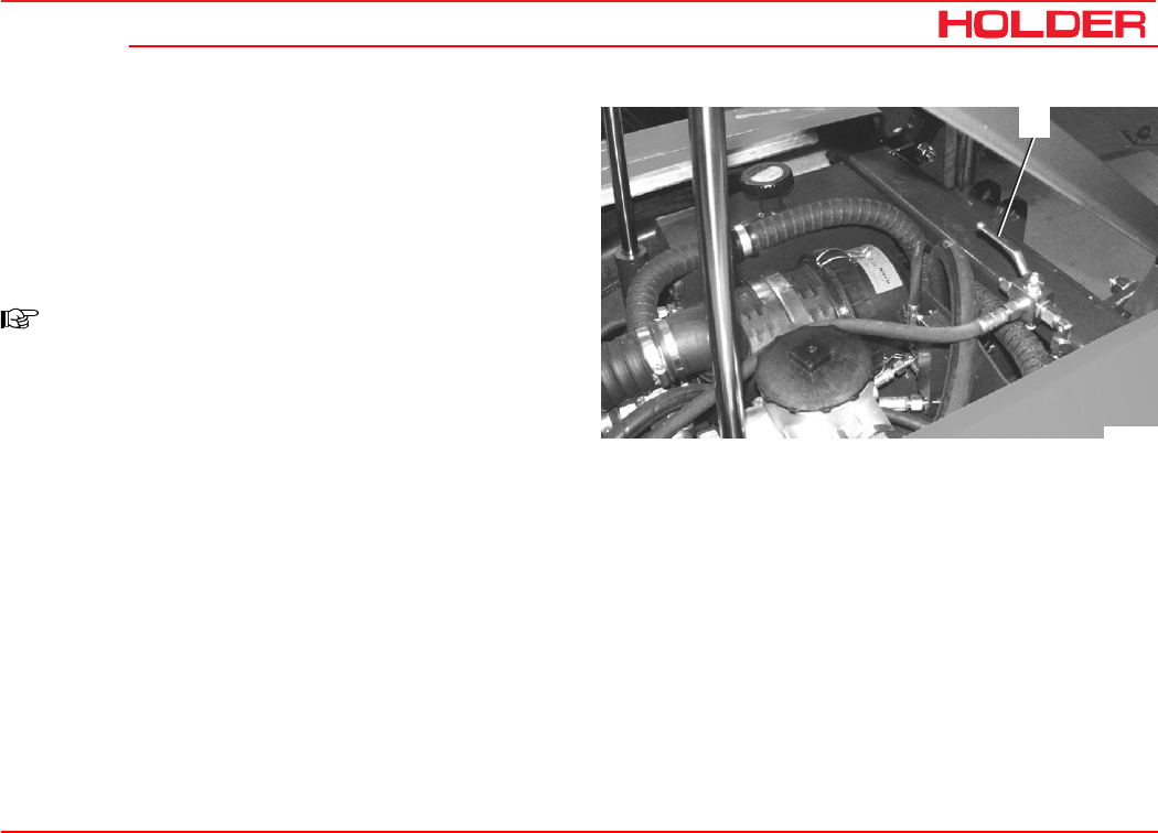
Operating instructions
149 443 155
C 4.74 General remarks on maintenance
1
Bild_C238
Securing the dump body (loading platform*)
For all services requiring the dump body (loading platform*)
to be raised, secure it against accidental lowering.
- Turn the changeover lever (1) to the right (hydraulic
lock).
NOTE
To lower it, return the changeover lever (1) to
the left.
* Option
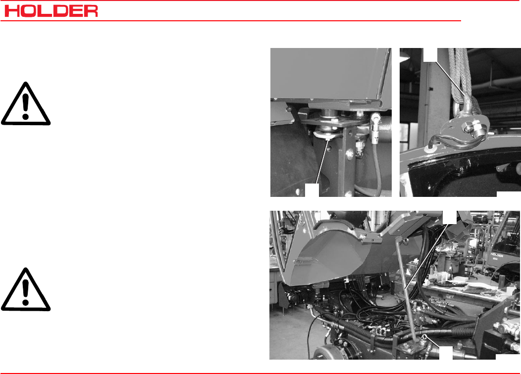
C 4.74
Operating instructions
156 149 443
General remarks on maintenance
3
4
Bild_C240
2
1
Bild_C239
Tilting the cab
The cabin can be tilted for repairs and servicing.
ATTENTION
Raise the cabin carefully.
- Remove the front fender by removing the socket head
screw and pushing the roller back.
- Remove the nuts (1) and retaining plate at the rear of
the cabin.
- Attach the M14 eyebolt* (2) to the top of the cab
frame.
- Attach a hook or rope and slowly lift the cabin up with
a hoist.
- Take the stay rod (3) out of the support, insert it on
the vehicle frame and secure it with the retaining pin
(4).
DANGER
Working under the cabin is only allowed with
the stay rod in place.
* Option (commercially available)

Operating instructions
149 443 157
C 4.74
Maintenance schedule
Maintenance during the first period of operation
The checks and services specified below must be carried
out when the stated number of service hours is reached.
The checks and services of the lower intervals must be
carried out at the same time.
Example:
At 1000 hours of operation, the checks and services for
500 and 125 hours must also be carried out.
Interval Service or check See page
Maintenance after the first 50
hours
Check the engine for leaks
Check the hydraulic oil level
Check the braking system
Grease the vehicle
Tighten nuts and bolts
Tighten wheel nuts
159
48
168
169, 180
170
170
Maintenance after the first
500 hours
Change hydraulic oil for traction and working hydraulics
Clean the filter for the traction and workin
g
hydraulics
return line and change it, if necessary
Check or clean hydraulic oil suction filter of implement
hydraulics
181
182
182

C 4.74
Operating instructions
158 149 443
Maintenance schedule
Interval Service or check
Maintenance as required Adjust the speedometer
Check the air cleaner system
Periodic maintenance
Maintenance every 125 hours Check the cooling system
Clean cooling system
Check the battery and cable terminals
Check hydraulic oil level, see page 48
Check the high pressure hoses
Check the steering cylinder and orbitrol
Check the brake fluid level for the foot brake
Check the braking system
Grease the vehicle
Tighten nuts and bolts
Tighten wheel nuts
Check the electrical system
Clean the fresh air filter
Maintenance every 500 hours Change the engine oil
Change the engine oil filter
Check hose couplings for leaks
Check the heating system
Routine maintenance

Operating instructions
149 443 159
C 4.74 Maintenance schedule
Interval Checks and services
Maintenance every 1000 hours Check engine valve clearances
Check the battery
Check V-belt tension and condition
Change the fuel filter
Clean/replace the fuel pump strainer
Lubricate the cardan joint nipples
Maintenance every 1500 hours Change hydraulic oil for traction and working hydraulics
Clean the filter for the traction and workin
g
hydraulics return line
and change it, if necessary.
Check / clean for suction filter for working hydraulic system.
Maintenance every 3000 hours Check the injection nozzles
Change the toothed belt
Annual maintenance Change the brake fluid of the foot brake
Periodic maintenance

Operating instructions
149 443 161
C 4.74
Maintenance during the first period
of operation
The following checks and services are due during the first
period of operation:
Maintenance after the first 50 hours
Maintenance after the first 150 hours
Maintenance after the first 500 hours
Maintenance after the first 50 hours
Check the engine for leaks
- Raise the dump body (loading platform*) and secure it
against accidental lowering.
-Check the engine and implements for leaks.
Carry out the other services in accordance with the mainte-
nance schedule. You can find the description of the serv-
ices using the indications in the maintenance schedule or
in the alphabetical index.
* Option
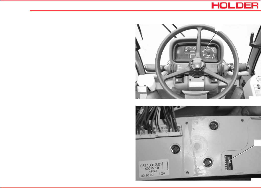
Operating instructions
149 443 163
C 4.74
1
Bild_C241
2
Bild_160
Maintenance as required
Adjusting the speedometer
The adjustment of the speedometer in the multifunctional
display is required when changing from large to smaller tires
and vice versa.
- Carefully pull the multifunctional display (1) out at the
right and left side and rotate it.
- Remove the cover from the combination switch (2) on
the back.
- Set the first 6 of 8 DIP switches to the positions
shown in the table as required for the size of your
tires.

C 4.74
Operating instructions
164 149 443
Maintenance as required
- Switch positions 7 and 8 are not used.
- Refit the multifunctional display.
Switch layout
Combination
Tire size Type 12 3 4 5 6 7 8
340/65 R18 422-31-06 & 422-31-07 1 0 1 1 0 - -
275/80 R18 4131-14 & 422-31-2 1 0 1 0 1 0 - -
36x13.50-15 204-31-03 1 0 1 0 1 0 - -
10.5-18 MPT 4131-22 & 422-31-3 1 0 1 0 1 0 - -
320/65 R18 422-31-4 & 422-31-05 1 0 1 0 1 0 - -
425/55 R17 204-31-02 1 0 1 0 1 0 - -
33x12.50 R15 4131-23 1 0 1 0 1 0 - -
33x15.5-15 4131-18 1 0 1 0 1 0 - -
33/18LL-16.1 204-31-01 1 0 1 0 1 0 - -
31x11.50 R15 203-31-1 1 0 1 1 0 0 - -
31x15.5-15 4131-8 1 0 1 1 0 0 - -
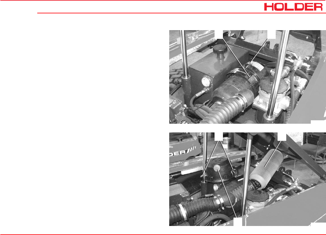
Operating instructions
149 443 165
C 4.74 Maintenance as required
1 2
Bild_C242
32
4
Bild_C243
Check the air cleaner system
The filter cartridge must be serviced when the flow resist-
ance of the filter is highest due to the restriction of the ele-
ment. This is indicated by the sounding of an alarm.
-Stop the engine.
-Raise the dump body (loading platform*) and secure it
against accidental lowering.
-Remove the clamping band (1) from the air cleaner
housing and turn the air cleaner housing up.
-Open the air cleaner cover clips (2).
-Pull off the housing cover and clean the dust ejection
valve (4).
-Pull the air filter element (3) out of the housing by
rotating it slightly.
Cleaning:
- Blow out the filter element from the inside with com-
pressed air having a pressure of maximum of 5 bar.
Replacement:
- Install a new filter element.
Clean the air cleaner housing with a moist cloth before in-
stallation.
The installation of the air filter element is performed in the
reverse order.
* Option
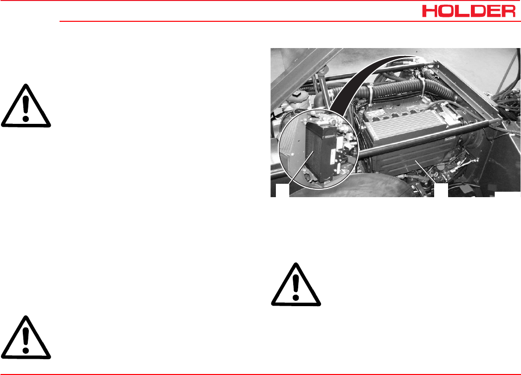
Operating instructions
149 443 167
C 4.74
Bild_C245
21
Periodic maintenance
Maintenance every 125 hours
ATTENTION
Carry out the checks and services only with
the engine turned off.
Check the cooling system
-Inspect the cooling fins and oil cooler for the accumu-
lation of dirt.
Clean the cooling system
Clean with compressed air
- Raise the dump body (loading platform*) and secure
it against accidental lowering.
- Remove the left and right side panels.
-Remove the cover plate (1) at the right-hand side of
the engine.
- Blow dirt out of the engine compartment taking special care
on the radiator and radiator fins (start from the exhaust air
side). Remove any dirt blown into the engine compartment.
- Clean the hydraulic oil cooler (2) in the same way.
Clean with cold cleaner or pressure washer
ATTENTION
Max. spray pressure is 60 bar. Steam tem-
perature is 60°C
-Preparations as described above.
-Spray the oil cooler and engine with a cold cleaner
and allow it to soak in for 10 minutes.
-Clean the oil cooler and engine with a strong water jet.
ATTENTION
Do not aim the water jet directly at sensitive
parts such as the alternator. Cover them if
necessary.
-Run the engine warm to evaporate any water residues.
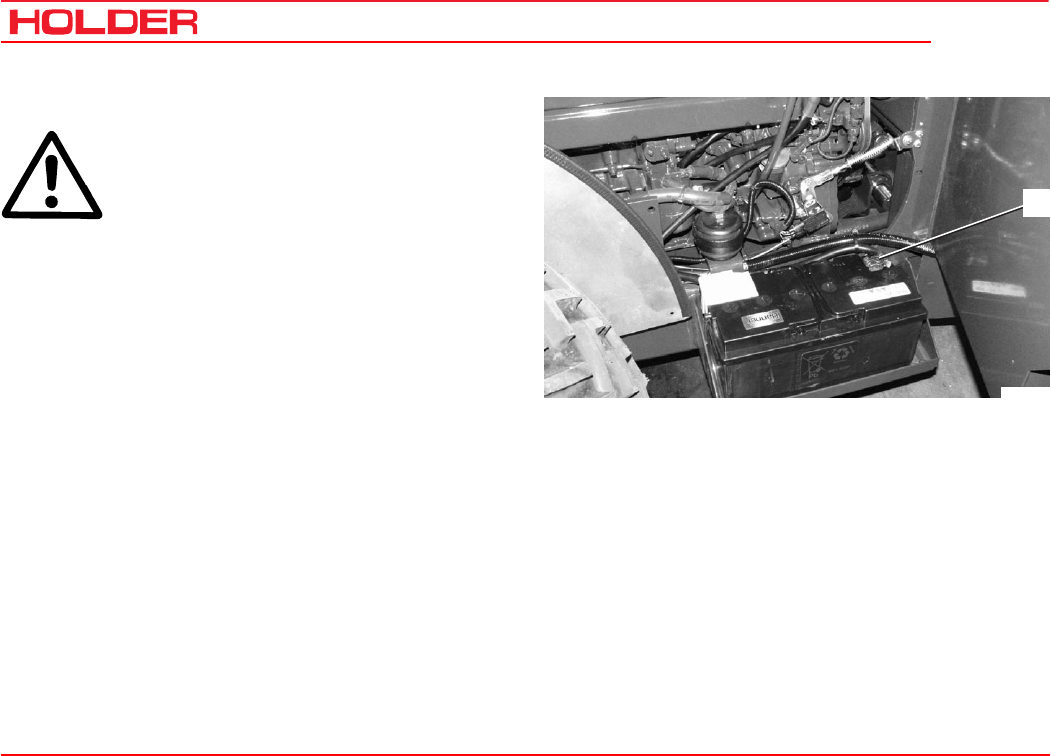
C 4.74
Operating instructions
168 149 443
Maintenance every 125 hours
1
Bild_C246
Check the battery and cable terminals
CAUTION
When working on the electrical equipment,
always disconnect the ground lead (1) at the
battery.
- Check the battery acid level and inspect the battery
for leaks. Observe the information of the battery
manufacturer.
- Remove any corrosion on the battery terminals.
- Grease the battery terminals with non-acidic battery
grease.
- Check cables and cable ends for secure connection
and damage.
- Replace any damaged cables and terminals.
Check the high pressure hoses
- Check the high pressure hoses for cracks, bending
and chafing, and for porous surfaces.
Replace damaged high-pressure hoses immediately.
This work may only be carried out by an authorized work-
shop.

Operating instructions
149 443 169
C 4.74 Maintenance every 125 hours
Bild_C247
1
Bild_C248
Check the steering cylinder and orbitrol
- Check the steering cylinder and orbitrol for damage
and leaks.
- Have damaged or leaky parts replaced by an author-
ized workshop.
Check the brake fluid level for the foot brake
- Check the brake fluid reservoir for the foot brake (1).
The brake fluid level must be between the markings.
- To fill brake fluid, unscrew the reservoir cap (1) and
fill recommended brake fluid as far as the marking.
Filling capacity ......................................... approx. 0.4 L
ATTENTION
Do not mix different kinds of brake fluids.
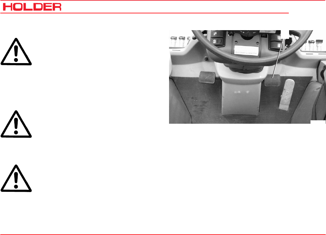
C 4.74
Operating instructions
170 149 443
Maintenance every 125 hours
1
Bild_C249
Check the braking system
DANGER
Do not operate the vehicle with a defective
braking system.
- Apply the parking brake.
- Set the vehicle to driving range 1 or 2 and start
driving slowly.
A noticeable resistance should be felt when starting
to drive and an alarm should sound.
CAUTION
When the foot brake pedal (1) is depressed,
the vehicle is braked strongly.
-Depress the foot brake pedal (1) while driving slowly.
The vehicle should brake strongly.
DANGER
In case of irregularities with the braking sys-
tem, stop the vehicle immediately and have
it checked by an authorized workshop.
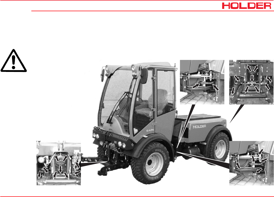
Operating instructions
149 443 171
C 4.74 Maintenance every 125 hours
Bild_C250
1 1
12
Grease the vehicle
- Grease all moving parts lightly.
-Lubricate the grease nipples (1) according to the lubrication chart. Only use recommended grease.
ATTENTION
Lubricate the grease nip-
ples (2) only every 1000
hours. (Do not inject too
much grease to prevent
damage to the seal.)
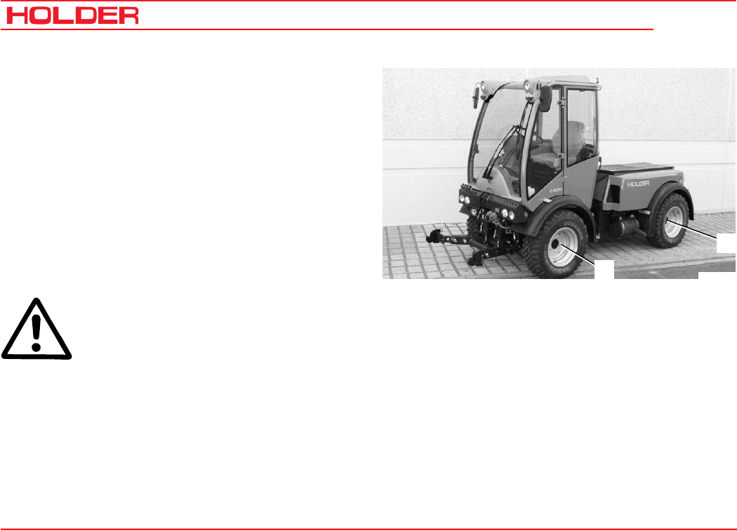
C 4.74
Operating instructions
172 149 443
Maintenance every 125 hours
Bild_C251
1
2
Tighten nuts and bolts
- Tighten the pump, axle and engine fasteners.
- Tighten fasteners to the specified torque according to
tables in the maintenance data.
Tighten wheel nuts
- Tighten all wheel nuts on the front and rear wheels (1
and 2).
Torque................................................................ 215 Nm
Check the electrical system
CAUTION
When working on the electrical system, al-
ways disconnect the ground lead of the bat-
tery!
- Raise the dump body (loading platform*) and secure it
against accidental lowering.
- Check cables, plugs and cable ducts for damage and
security.
- Have any damaged parts replaced by an authorized
workshop.
* Option
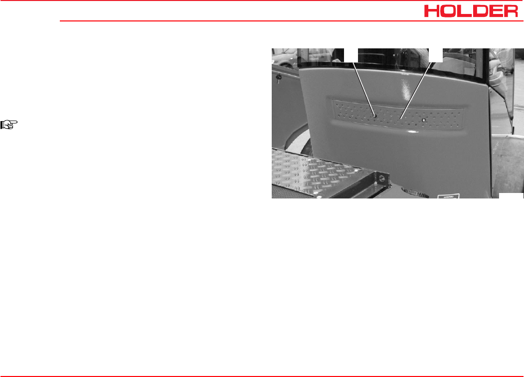
Operating instructions
149 443 173
C 4.74 Maintenance every 125 hours
21
Bild_C252
Clean the fresh air filter
- Remove the fastening screws (1).
- Remove the filter cover (2) and take out the filter
element.
- Clean the filter element or replace it.
NOTE
A charcoal filter* is available for applications
such as spraying insecticides, etc.
- Install the filter element and refit the filter cover.
* Option
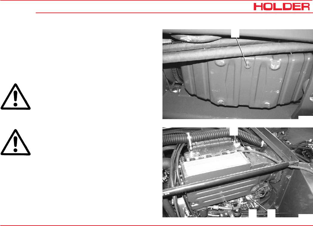
Operating instructions
149 443 175
C 4.74
1
Bild_C253
2
23
Bild_C254
Maintenance every 500 hours
Change the engine oil
- Run the engine warm to operating temperature.
- Set the heating control to high.
- Place the vehicle on level ground and turn off the engine.
- Place a suitable oil pan underneath the engine.
CAUTION
Danger of scalding when draining hot engine
oil.
- Unscrew the oil drain plug (1).
- Allow the oil to drain completely.
ATTENTION
Observe the instructions for handling fuels
and lubricants.
- Refit the oil drain plug with a new gasket and tighten
it to a torque of 55 Nm.
- Fill new engine oil at the filler neck (2). Only use
recommended engine oil.
Filling capacity with filter and heater ............ 10.5 litres
- Let the engine idle briefly.
- After approx. 1 minute, check the oil level with the
dipstick (3).
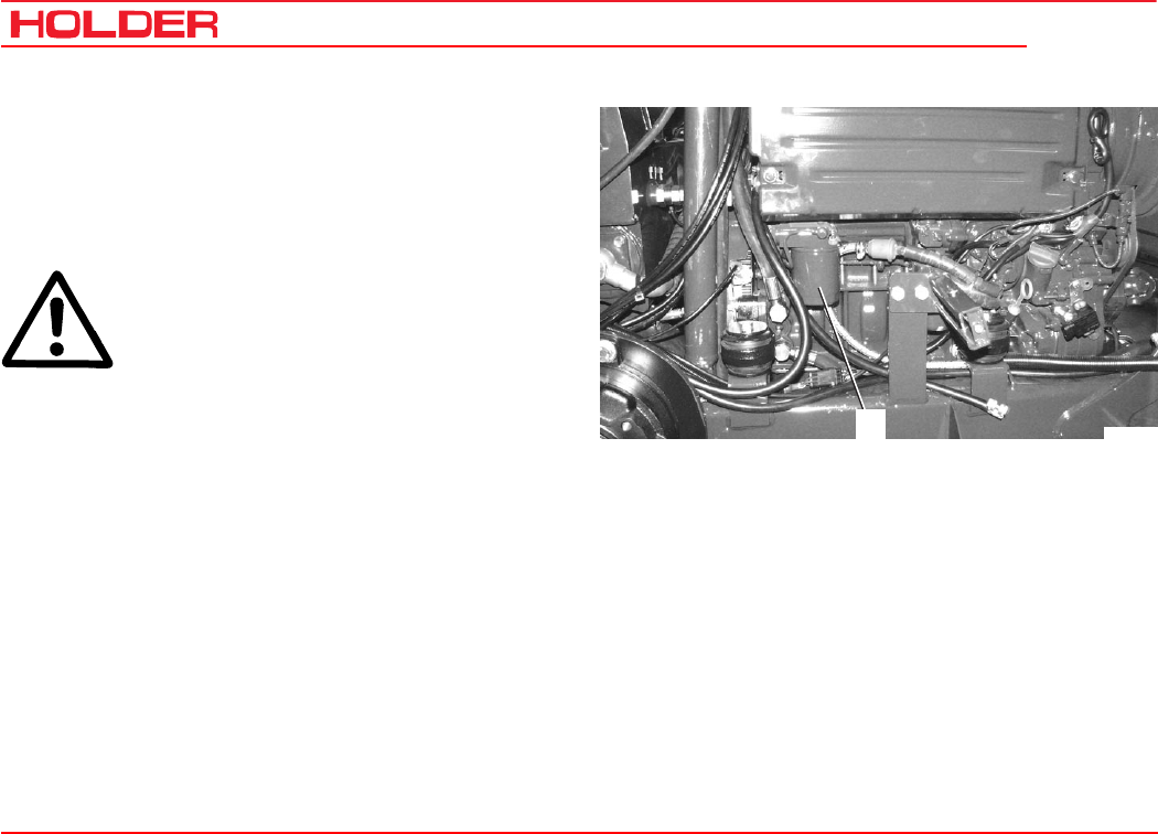
C 4.74
Operating instructions
176 149 443
Maintenance every 500 hours
1
Bild_C255
Change the engine oil filter
See the operating instructions of the engine manufacturer.
- Drain the engine oil.
- Remove the filter element (1) with a filter wrench.
ATTENTION
Observe the instructions for handling fuels
and lubricants.
- Clean the sealing surface of the filter element mount-
ing base.
- Install a new filter element with a new gasket until the
gasket contacts the base.
- Tighten the filter element half a turn.
- Top up engine oil. Check the oil level.
Check hose couplings for leaks
- Check all hose couplings for leaks. Use leakage
spray if necessary. Eliminate any leaks immediately.
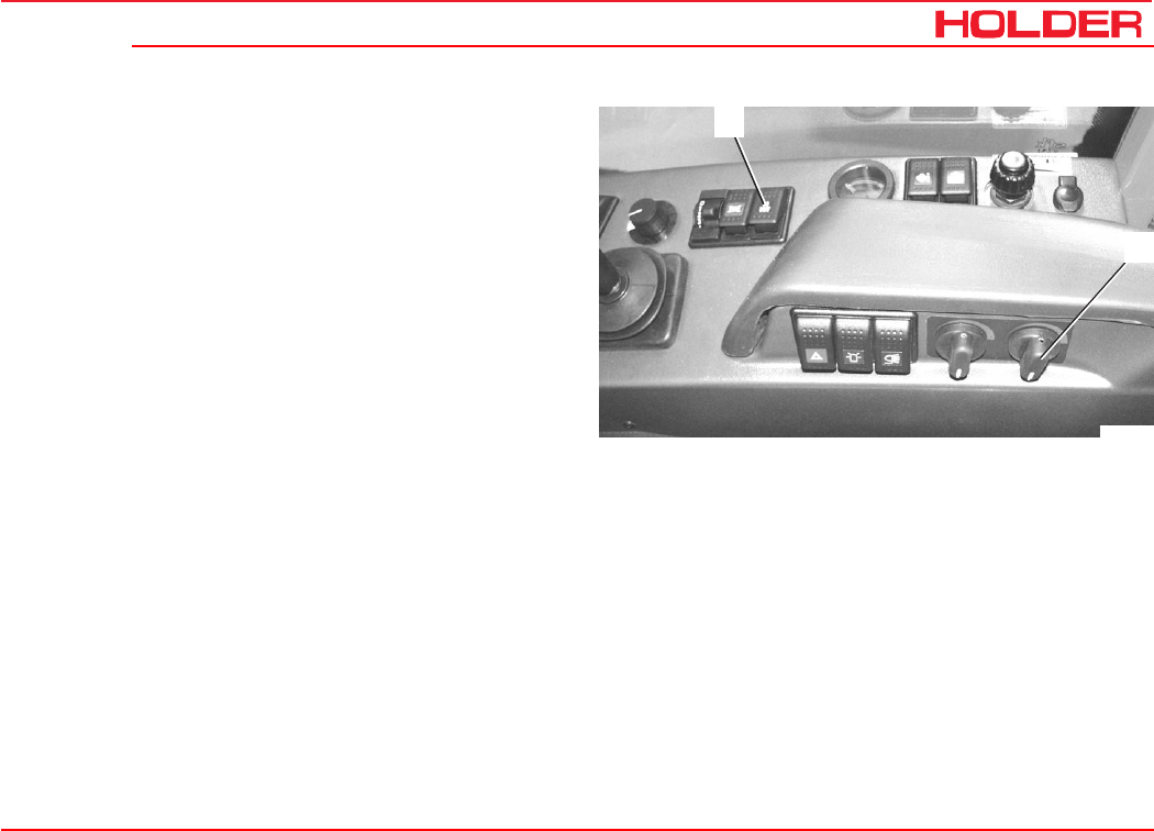
Operating instructions
149 443 177
C 4.74 Maintenance every 500 hours
2
1
Bild_C273
Check the heating system
- Turn the rotary knob (2) CCW to the OFF position.
- Run the engine warm.
- Turn the rotary knob (2) CW to the ON position.
- Set the heating blower switch (1) to stage 2. Warm air
should flow out of the heating nozzles.
Operating instructions
149 443 179
C 4.74
Maintenance every 1000 hours
Check engine valve clearances
See the operating instructions of the engine manufacturer.
Check the battery
CAUTION
For the sake of your safety, observe the fol-
lowing instructions.
The battery contains dissolved sulphuric acid,
which is poisonous and caustic.
When working with battery acid, wear per-
sonal protective equipment (protective apron,
protective gloves) and eye protectors. If your
clothing, skin or eyes have nevertheless
come in contact with battery acid, the affected
parts must be rinsed at once with water. If
the eyes are affected, seek medical aid im-
mediately. Neutralise spilled battery acid im-
mediately.
Gases are released when batteries are
charged. To prevent an explosion, keep
sparks, naked fires away. Rooms, in which
batteries are charged or stored, must be ven-
tilated accordingly.
NOTE
The charging, servicing and care of the bat-
tery must always be according to the main-
tenance instructions of the battery manufac-
turer.

C 4.74
Operating instructions
180 149 443
Maintenance every 1000 hours
Check V-belt tension and condition
See the operating instructions of the engine manufacturer.
CAUTION
Service V-belts only with the engine station-
ary.
- Inspect V-belts for cracks and tears over the entire
length.
- Replace damaged V-belts.
- Using thumb pressure, check if the V-belt can not be
depressed more than 10 - 15 mm.
- To tighten V-belts: Loosen the idler pulley mounting
screws and push the pulley outwards until the proper V-
belt tension is reached.
- Tighten the idler pulley mounting fastening screws.

Operating instructions
149 443 181
C 4.74 Maintenance every 1000 hours
Change the fuel filter and fuel prefilter
See the operating instructions of the engine manufacturer.
- Remove the fuel filter cartridge with a filter wrench.
ATTENTION
Observe the instructions for handling fuels
and lubricants.
- Clean the sealing surface of the filter base.
- Coat the new gasket with oil.
- Install the new filter cartridge with a new gasket in the
filter base and tighten by hand.
NOTE
The fuel system is bled automatically.
Clean / replace the fuel pump strainer
See the operating instructions of the engine manufacturer.
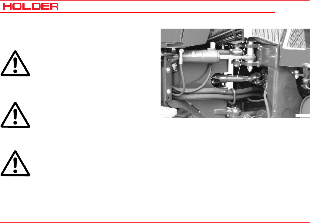
C 4.74
Operating instructions
182 149 443
Maintenance every 1000 hours
1
Bild_C258
Lubricating the cardan joint nipples
- Steer the vehicle as far as steering stop.
CAUTION
Carry out services in the articulated joint area
only with the engine shut off.
- Move centre cardan shaft (1) with starter until grease
nipples are easily accessible.
CAUTION
Make sure no-one is standing in the area of
the articulated joint when the starter is oper-
ated.
- Grease the cardan shaft and cardan joints.
CAUTION
Do not inject too much grease to prevent
damage to the seal.
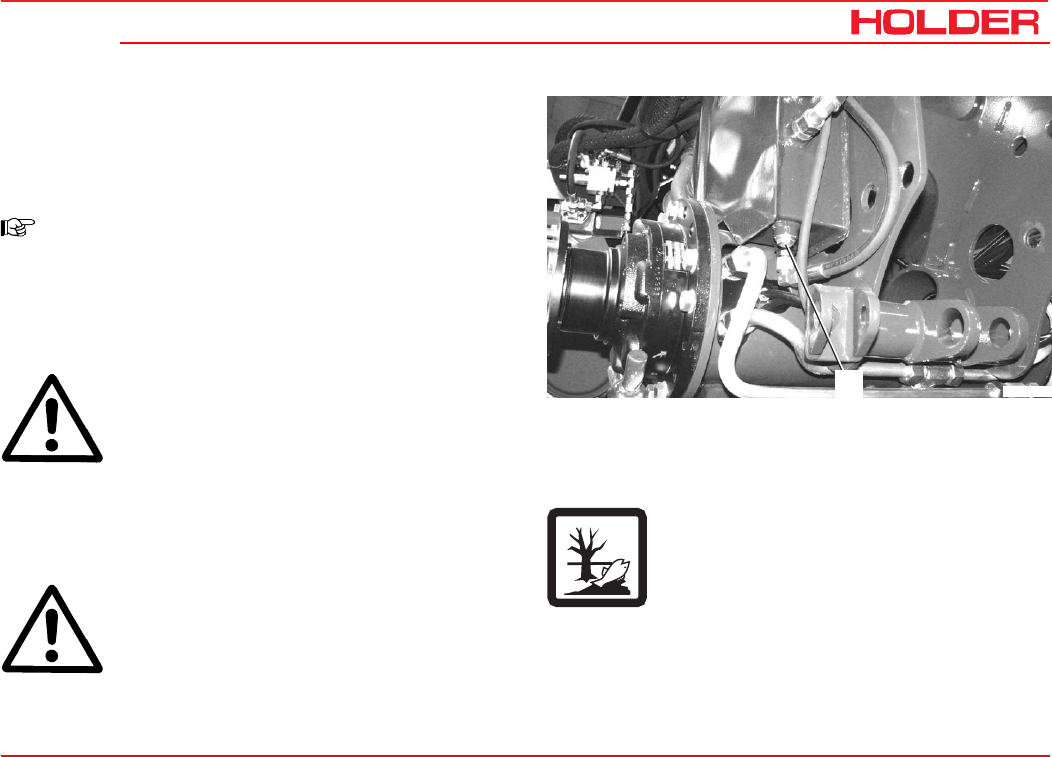
Operating instructions
149 443 183
C 4.74
1
Bild_C259
Maintenance every 1500 hours
Change hydraulic oil for traction and working hydrau-
lic system
NOTE
Change the hydraulic oil while at operating
temperature.
-Place the vehicle on level ground. Raise the dump
body.
CAUTION
Secure the dump body (loading platform)*
against accidental lowering.
-Place a suitable oil container beneath the hydraulic oil
tank.
-Relieve any pressure in the hydraulic system by
operating the control levers.
CAUTION
Danger of scalding when draining hot hydraulic
oil.
-Unscrew the oil drain plug (1).
- Drain the oil.
Please ensure the oil is disposed of
properly.
-Flush the hydraulic oil tank with clean hydraulic oil if
necessary.
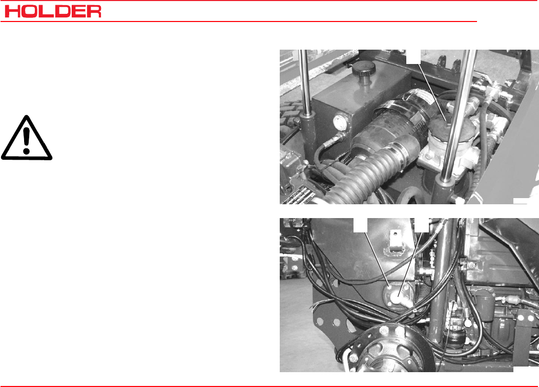
C 4.74
Operating instructions
184 149 443
Maintenance every 1500 hours
1
Bild_C260
2 3
Bild_C261
Clean the filter for the traction and working hydraulics
return line and change it, if necessary.
-Remove the filter cover (1).
-Pull the filter element out.
ATTENTION
Observe the instructions for handling fuels
and lubricants.
Clean:
- Clean the filter element with clean diesel fuel.
Change:
- Install a new filter element in filter housing.
Refitting is the reverse of removal.
Check / clean the suction filter for working hydraulic
system
- Remove the banjo bolt (3) and move the line to the
side.
- Remove the filter cover fastening screws (2).
- Pull the filter housing out with the straining star filter.
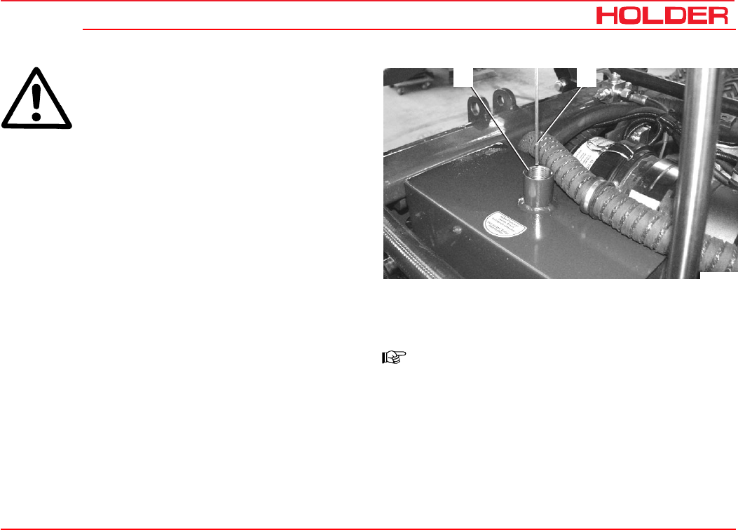
Operating instructions
149 443 185
C 4.74 Maintenance every 1500 hours
Bild_C262
4 5
ATTENTION
Observe the instructions for handling fuels
and lubricants.
Clean:
- Wash the straining star filter with clean diesel fuel.
Change:
- Remove the straining star filter from the filter housing
with a 24mm open-ended wrench.
- Fit a new toroidal sealing ring on the new filter and
screw it on to the filter housing.
Refitting is the reverse of removal.
- Refit the oil drain plug with a new seal. Check for oil
leaks.
-Fill recommended hydraulic oil through the filler neck
(4).
Filling capacity .................................... approx. 42 litres
-Check the oil level with the oil dipstick (5).
-Refit the filler neck cap.
-Start the engine. Operate the implements and steering.
-Drive the vehicle briefly back and forth.
NOTE
The air in the hydraulic system is bled auto-
matically.
-Shut off the engine and relieve any pressure in the
hydraulic system.
- Check for leaks.
-Check the oil level with the oil dipstick (5). Add
hydraulic oil if necessary.

Operating instructions
149 443 187
C 4.74
Maintenance every 3000 hours
Check the injection nozzles
ATTENTION
This work may only be carried out by an au-
thorized workshop.
- Clean the injection nozzles.
- Check the injection nozzles with a test pressure of
250 +8 bar.
Change the toothed belt
Change every 3000 hours or 5 years maximum.
See maintenance instructions of the engine manufacturer.
ATTENTION
This work may only be carried out by an au-
thorized workshop.
- Remove the left-hand cover of the toothed belt drive.
- Check the toothed belt for cracks over its entire length.
- Replace damaged toothed belts.
NOTE
When replacing the toothed belt, also replace
the idler pulley.

Operating instructions
149 443 189
C 4.74
Annual maintenance
Change the brake fluid of the foot brake
ATTENTION
This work may only be carried out by an au-
thorized workshop.
Operating instructions
149 443 191
C 4.74
Laying up
If the vehicle is not going to be in service for over 2 months,
for example for operational reasons, it must be placed in a
well-ventilated, clean and dry room and the following meas-
ures must be carried out.
- Clean the vehicle thoroughly.
- Check the hydraulic oil levels, topping up oil if neces-
sary
- Cover all blank mechanical components with a thin
film of oil or grease.
- Grease the vehicle.
- Check the condition and acid density of the battery;
cover the battery terminals with non-acidic grease.
(Observe the instructions of the battery manufacturer.)
- Remove the battery and store in a frost-free, dry
room.
Engine preservation
- Clean the engine.
- Run the engine warm.
- Drain the engine oil and refill with anti-corrosion oil.
- Drain the fuel and fill up the fuel tank with a mixture of
90 % diesel fuel and 10 % anti-corrosion oil. Mixing
ratio of diesel fuel 90 %, anti-corrosion oil 10 %.
- Run the engine for 10 minutes.
- Shut off the engine.
- Crank the engine a few times by hand.
- Seal the intake and exhaust openings.
ATTENTION
The vehicle must be blocked up so that all
the wheels are off the ground. This will pre-
vent a permanent deformation of the tires.
NOTE
Do not use plastic foil to cover the vehicle as
this enhances the formation and collection
of condensate water.
Putting the vehicle back in service after lay-up
If the vehicle was taken out of service for over six months,
it must be inspected carefully before being put back in serv-
ice. The inspection should, similar to the safety inspection,
also cover all safety relevant components of the vehicle.
- Clean the vehicle thoroughly.
- Grease the vehicle.
- Check the condition and acid density of the battery,
recharge it if necessary.

C 4.74
Operating instructions
192 149 443
Laying up
Remove engine preservation
- Unblock the intake and exhaust openings.
- Drain the anti-corrosion oil and rinse the oil sump with
engine oil.
ATTENTION
Observe the instructions for handling fuels
and lubricants.
See the section „Change the engine oil“ on how to proceed
further.
- Check the hydraulic oil for condensed water, change
the oil if necessary.
- Perform the checks and services as for before taking
into service.
- Fill the fuel tank.
- Change the brake fluid.
- Take the vehicle into operation.
When taking into the vehicle into service, particularly check:
- Variable-displacement pumps and wheel motors for
leaks.
- Drive hydraulics, gearshift, steering.
- Brake (service brake, parking brake)
- Working hydraulics, functions and work movements.
If the vehicle is to be laid up for a longer period, please
contact your HOLDER Service for further measures.

Operating instructions
149 443 193
C 4.74
Fuel and lubricant recommendations
Recommended hydraulic and gear oils
Manufacturer Hydraulic oils
HE oils (hydr. ester) Gear oils
Utto / Stou
ISO viscosity class
HLP (HM) HV VG 46
AGIP Agip Arnica S 46 Agip Rotra JDF
ARAL Vitam EHF 46 Aral Fluid HGS 10W30
AVIA Syntofluid N46 -----
BECHEM Hydrostar HEP 46 -----
BP Biohyd SE 46 – S BP Hydraulic TF - JD
BAYWA Plantosyn 3268 ECO -----
BUCHER & CIE Motorex Biosynt 3268 Farmer 304 JD-M20C
DEA Econa E 46 -----
ESSO Univis HE ES 46 Unifarm 15W - 40
TOTAL
TOTAL
TOTAL
Total Biohydran SE 46
Total Biohydran TMP 46 Tractorelf ST3 15W-30
Total Multagri Super 10W-30
Total Multi TP Max 10W-40
FUCHS
FUCHS Plantohyd 46 S-NWG
Plantosyn 3268 -----
-----
OEST Bio Synthetic HYD 46 -----
SHELL Naturelle HF – E 46 Shell Harvella T 10W-30
VALVOLINE Valvoline Ultraplant ------

C 4.74
Operating instructions
194 149 443
Fuel and lubricant recommendations
Recommended engine oils and greases
The following oil brands conform to US Military Specifica-
tion MIL-L-2104C or to API quality CD/SF and ACEA.
Manufacturer Lubricating oil type SAE
Class
Greases
Penetration ratio
260 - 290
AGIP
AGIP AGIP Sigma Ultra TFE
Autol Valve Ultra FE 10W-40
10W-40 AGIP GR MU 2
ARAL
ARAL ARAL Mega Turboral
ARAL Super Turboral 10W-40
5W-30 Multipurpose grease
Long-duty grease H
BAYWA
BAYWA BayWa Super Truck 1040 MC
BAYWA Turbo 4000 10W-40
10W-40 BAYWA Multigrease 2
Special Grease FLM
BP OIL International BP Vanellus HT Extra 10W-40 BP Energrease LS 2
BP Multipurpose Grease L2
CASTROL GmbH
CASTROL GmbH Castrol SYNTRUCK
Castrol DYNAMAX 5W-40
7.5W-40 Castrol LM
CHEVRON Chevron Delo 400 Synthic 5W-40
DEA
DEA
DEA
DEA Cronos Synth
DEA Cronos Premium LD
DEA Cronos Premium FX
5W-30
10W-40
10W-40
Glissando 20
Glissando 283 EP 2
ESSO Essolube XTS 501 10W-40 ESSO Multipurpose Grease
Beacon 2
FUCHS
FUCHS FUCHS Titan Cargo MC
FUCHS Titan Unic Plus MC 10W-40
10W-40 Renolit LZR 2

Operating instructions
149 443 195
C 4.74 Fuel and lubricant recommendations
Recommended engine oils and lubricants, continued
Brake fluid
ATE brake fluid SL / DOT 4
DANGER
Do not use mineral oil.
Manufacturer Lubricating oil type SAE
Class Greases
Penetration ratio
260 - 290
MOBIL OEL
MOBIL OEL
MOBIL OEL
Mobil Delvac 1 SHC
Mobil Delvac 1
Mobil Delvac XHP Ultra
5W-40
5W-40
10W-40
Mobilgrease MB 2
SHELL International SHELL Myrina TX/
SHELL Rimula Ultra
5W-30 Retinax EP2
SHELL International SHELL Myrina TX/
SHELL Rimula Ultra
10W-40
Schmierölraffinerie
Salzbergen
Wintershall TFG 10W-40
TOTAL TOTAL Rubia TIR 8600 10W-40 Total Multis EP2
Total Lical EP2
Fuels
Observe the specifications of the engine manufacturer.
NOTE
The use of bio diesel fuel is only allowed af-
ter a conversion of the engine by an author-
ized workshop.

Operating instructions
149 443 197
C 4.74
* NOTE
In order to ensure the biological degradability
of the hydraulic oil, all implements connected
to the vehicle hydraulic system must also be
operated with HE oils.
Filling quantities C 4.74
Engine oil
Incl. filter 0.5 litres
Incl. heater 0.75 litres
10.5 litres
Hydraulic oil tank for traction and working hydraulics,
hydraulic oil*
Initial filling (depending on equipment)
approx. 42 litres
approx. 58 litres
Front PTO gear 1.25 litres permanent filling
Rear PTO gear 1.25 litres permanent filling
Brake fluid for footbrake 0.4 litre
Fuel tank, diesel fuel 60 litres
Washer reservoir approx. 1.3 litres
Residual quantities of mineral oils reduce the
biological degradability. They do not influence
operation.
Maintenance data

C 4.74
Operating instructions
198 149 443
Maintenance data
Tightening torques
Hexagon screws and studs M 8 M 10 M 12 M 14 M 16
Screw quality 8.8 25 Nm 49 Nm 86 Nm 135 Nm 210 Nm
Screw quality 10.9 35 Nm 69 Nm 120 Nm 190 Nm 295 Nm
Hydraulic system, wheels Torque
M10 hex head screws (orbitrol
to steering supports) 40 Nm
Clamping screws for hydraulic
control valves 16 Nm
Wheel fasteners 215 Nm
Engine Torque
Cylinder head cover 8.5 Nm
Rocker arm setscrew 21 Nm
Intake manifold 8.5 Nm
Intake tube (TORX) 21 Nm
Exhaust manifold (TORX) 22 Nm
Oil drain plug 55 Nm
Oil sump 21 Nm
Injection line fastener 30 Nm
Injection valve fasterner
(TORX) 21 Nm
Plugs and connecting screws
for heating hoses 65 + 5 Nm

Operating instructions
149 443 199
C 4.74 Maintenance data
List of replacement parts
Description Order No.
Drain plug seal 010 395
Engine oil filter 797 135
Fuel filter 782 971
Fuel prefilter 797 709
Cylinder head cover gasket 797 586
Air cleaner element 141 652
V-belt for KHD fan 796 808
Toothed belt repair kit 797 587
Return line filter (working and traction hydraulics) 030 610
Suction filter (working hydraulics) 029 540
Toroidal sealing ring 64x3 014 696 (2 items)
Filter element (fresh air filter for cabin) 131 666
Ventilation filter with active charcoal (fresh air filter for cabin) 131 667
Can of spray paint, black grey RAL 7021 029 000
Can of spray paint, orange RAL 2004 020 656
Can of spray paint, silver RAL 9006 031 053

C 4.74
Operating instructions
200 149 443
Maintenance data
Bulbs 12 V
Lights Rating Lights Rating
Headlight, dip beam H7 55 W Flood light, front top H7 55 W
Headlight, high beam H7 55 W Flood light, rear H3 55 W
Turn signal light, front 21 W Indicator lights in switch 1.2 W
Turn signal light, rear 21 W Indicator light, yellow 3 W
Tail light 10 W Clearance lights 5 W
Licence plate light 5 W Interior light 5 W
Stop light 21 W Rotating beacon H1 55 W
Back-up light 21 W Multifunctional display bulbs
DIN 72601/W5/12 V 1.2 / 3.0 W

Operating instructions
149 443 201
C 4.74 Maintenance data
Engine specifications
C 4.74
Manufacturer Deutz AG
Model BF4L 2011 COM II
Type Vertical in line
Mode of operation 4-cycle diesel
Cooling Integrated oil/air cooling
Injection mode Direct fuel injection
Number of cylinders 4
Cylinder bore Ø 94
Stroke 112
Cubic capacity 3108 cm³
Compression ratio 1:17.5
Compression --------
Charging pressure 1.25 bar
Valve clearances with engine cold Inlet 0.3 mm
Exhaust 0.5 mm
Fuel consumption 229g/kWh at 1700-1850 rpm
Air filter Mann and Hummel dry filter with acoustic alarm
Lubrication system Forced-feed lubrication
Lubricating oil consumption 0.5% of fuel consumption maximum
Oil filter Change filter cartridge in main stream
Oil pressure at 900 rpm 2.0 – 2.5 bar
Rated speed 2500 rpm
Upper idle speed 2500 rpm + 350 rpm
Lower idle speed 900-980 rpm
Max. torque 241 Nm at 1500 - 1700 rpm
Rated power acc. to 97/68 EC
at n = 2500 rpm 54.6 kW (74 HP)

C 4.74
Operating instructions
202 149 443
Maintenance data
Fuel system
C 4.74
Injection pump Motorpal individual withdrawable element-
type calibrated pump
Governor Governor integrated in the front cover
Injection nozzle 5-hole nozzle
Injection pressure 850 bar
Start of fuel injection 0°+/-0.5° BTDC
Drive pump Hydrostatic drive
Axial piston pump
Type A4 VG40 EP1D1 / A4 VG40 EP1D1
Operating pressure 420 bar
Wheel motor Radial piston motor
Type MCR 05
Operating pressure 420 bar

Operating instructions
149 443 203
C 4.74
Page Page
Alphabetical index
A
Accessories ..................................................................43
Additional information on implements ............................78
Adjust the driver’s seat with mechanical suspension .....51
Adjust the steering wheel ..............................................50
Adjusting the backrest inclination ..................................52
Adjusting the driver’s seat with pneumatic suspension ..52
Adjusting the driver’s weight ..........................................53
Adjusting the fine control knob ......................................65
Adjusting the horizontal suspension ..............................53
Adjusting the hysteresis.............................................. 100
Adjusting the length of the pintle hook bar.....................82
Adjusting the lumbar padding ........................................52
Adjusting the pintle hooks and pintle hook bars.............82
Adjusting the seat horizontally ......................................53
Adjusting the speedometer................................. 135, 163
Adjusting the track width ...............................................74
Adjusting the upper link .................................................83
Air conditioning ........................................................... 121
Annual maintenance....................................................189
Applying the parking brake ............................................70
Applying the service brake ............................................70
Attaching implements ...................................................81
B
Ballast weights..............................................................75
Battery ..........................................................................14
Battery acid ..................................................................13
Bearing load ....................................................... 128, 129
Before starting to drive..................................................59
Brake fluid...................................................................195
Brakes ..........................................................................70
Bulbs 12 V .................................................................. 200
C
Change hydraulic oil for traction and
working hydraulics ............................................... 183
Change the brake fluid of the foot brake .....................189
Change the engine oil ..................................................175
Change the engine oil filter ..........................................176
Change the fuel filter and fuel prefilter ......................... 181

C 4.74
Operating instructions
204 149 443
Alphabetical index
Page Page
Change the toothed belt .............................................. 187
Changing the direction of travel .....................................67
Check / clean the suction filter for
working hydraulic system..................................... 184
Check and clean the cooler and debris screens ............45
Check engine valve clearances ................................... 179
Check hose couplings for leaks ..................................176
Check the air cleaner system......................................165
Check the battery........................................................179
Check the battery and cable terminals ........................ 168
Check the brake fluid level ............................................50
Check the brake fluid level for the foot brake ..............169
Check the brakes and steering for proper operation .......58
Check the braking system ..........................................170
Check the cooling system........................................... 167
Check the electrical system ........................................ 172
Check the engine for leaks..........................................161
Check the heating system ..........................................177
Check the high pressure hoses ...................................168
Check the hydraulic oil level .........................................48
Check the injection nozzles ........................................187
Check the lights and rear view mirror ............................54
Check the steering cylinder and orbitrol ....................... 169
Check the tire inflation pressure ....................................47
Check the trailer hitch (option) if required ......................47
Check V-belt tension and condition.............................. 180
Clean / replace the fuel pump strainer ........................ 181
Clean the cooling system ............................................167
Clean the fresh air filter ...............................................173
Clean with cold cleaner or pressure washer .................167
Clean with compressed air .......................................... 167
Cleaning the condenser ...............................................121
Connecting equipment to the power socket .................118
Connecting hydraulic lines ............................................84
Controls in cabin at front bottom ...................................37
Controls in cabin at front top .........................................37
Controls in cabin at rear ................................................38
D
Daily checks and services prior to
taking into operation ...............................................45
Date of issue and manual version .................................. 2
Description ....................................................................28
Development .................................................................. 1

149 443 205
C 4.74 Alphabetical index
Operating instructions
Page Page
Dimensional drawing .....................................................15
Disengaging the differential lock....................................68
Door controls.................................................................38
Driver’s licence............................................................... 7
Driver’s licence classes ................................................. 7
Driver’s station ..............................................................30
Driving ..........................................................................60
Driving on slopes ..........................................................72
Driving on-road with implement cushioning ..................101
Driving with hydrostatic drive and digital electronics......60
Driving with SDS (Special Drive System) ......................66
Driving with trailers ......................................................130
E
Emissions .....................................................................13
Engaging the differential lock ........................................68
Engine oil for winter operation .......................................75
Engine preservation ....................................................191
Engine specifications ........................................... 20, 201
Exhaust gas identification .............................................27
Exhaust gases ..............................................................13
Explanation of terminology ............................................. 2
External operation of the front power lift ........................92
External operation of the rear power lift .........................95
F
Filling fuel .....................................................................49
Filling washing water .....................................................54
Flow limiter for joystick .................................................93
Foreword ........................................................................ 1
Front Implement ............................................................79
Front left view ...............................................................28
Front windshield wiper/washer .....................................112
Fuel and lubricant recommendations ........................... 193
Fuels...........................................................................195
Fuses .........................................................................122
G
Gear oil, engine oil, diesel fuel ......................................12
General notes on safety ................................................11
General notes on service ............................................... 1
General remarks on maintenance ................................149
Grease the vehicle ...................................................... 171

C 4.74
Operating instructions
206 149 443
Alphabetical index
Page Page
H
Hand throttle .................................................................33
Handling fuels and lubricants ......................................151
Heat ..............................................................................14
Heater .........................................................................119
Heater until 04.2005 ......................................................35
Heating and ventilating ................................................119
Hoisting instructions.................................................... 131
How to value the vehicle? ...........................................149
Hydraulic oil, brake fluid ................................................13
Hydraulic system ..........................................................75
I
Identification plates .......................................................39
Indicators, adjustments ............................................... 135
Installing the cardan shafts ...........................................85
Instructions for the vehicle ............................................. 5
Instructions for transport .............................................131
Intended Use.................................................................. 5
Interior light .................................................................117
J
Jack lift points ............................................................ 154
Jacking up ..................................................................154
Joystick ........................................................................34
Joystick operation .........................................................87
L
Laying up .................................................................... 191
Leaving the vehicle ............................................ 125, 126
Lights ..........................................................................113
List of replacement parts ............................................199
Location of plates and labels .........................................39
Lubricating the cardan joint nipples .............................182
M
Maintenance after the first 50 hours ............................ 161
Maintenance as required ............................................. 163
Maintenance data........................................................197
Maintenance during the first period of operation . 157, 161
Maintenance every 1000 hours ...................................179
Maintenance every 125 hours .....................................167
Maintenance every 1500 hours ...................................183
Maintenance every 3000 hours ...................................187
Maintenance every 500 hours .....................................175

149 443 207
C 4.74 Alphabetical index
Operating instructions
Page Page
Maintenance schedule ................................................157
Mounting instructions for licence plates ........................40
Multifunctional display, legend.......................................36
Multiple-axle trailers or two-axle trailers with an
axle base over 1 metre ........................................... 9
N
Noise level ....................................................................27
Notes on disposal of vehicle .......................................... 6
Notes on starting ..........................................................55
Notes on the engine before starting up..........................55
O
Oil preheating ................................................................75
Opening the roof hatch ................................................111
Operating controls .........................................................30
Operating instructions .................................................... 7
Operating priority flow valve I ......................................106
Operating priority flow valve II .....................................108
Operating the air conditioning ......................................121
Operating the blue hydraulic couplings ..........................97
Operating the driver’s cab ...........................................111
Operating the front power lift .........................................88
Operating the front power lift with keyboard ...................89
Operating the green hydraulic couplings ........................97
Operating the hazard warning flasher system ..............116
Operating the horn ......................................................115
Operating the hydraulic couplings .................................96
Operating the hydraulic cushioning (front power lift) ....100
Operating the hydraulic dumper ...................................105
Operating the implements .............................................77
Operating the inching pedal ...........................................67
Operating the joystick ...................................................86
Operating the radio ......................................................118
Operating the rear power lift ..........................................94
Operating the roof hatch .............................................. 111
Operating the sideshift with the keyboard......................91
Operating the tilting device with the keyboard ...............90
Operating the trailer hitch automatically,
attaching trailers ..................................................129
Operating the trailer hitch manually,
attaching trailers ..................................................128
Operating the variable pump for implements
(setting from-0-100 litres) ..................................... 102

C 4.74
Operating instructions
208 149 443
Alphabetical index
Page Page
Operating the yellow and white hydraulic couplings .......97
Operation ......................................................................59
Operation in winter ........................................................75
Operation with implement cushioning ..........................101
Other activities............................................................111
Overview of options and variants (selection) .................41
P
Pedals ...........................................................................34
Periodic maintenance ......................................... 159, 167
Possible implements .....................................................77
Power socket .............................................................. 118
Problems in electronic and hydraulic driving systems . 137
Problems in engine and exhaust gas turbocharger ......137
Problems in the hydraulic system and steering ...........142
Problems in the working hydraulic system .................. 144
Putting on snow chains .................................................75
Putting the vehicle back in service after lay-up ...........191
Q
Qualification of service personnel ............................... 149
R
Radio and loudspeakers .............................................. 118
Rear console controls ...................................................33
Rear implement or front/rear combinations ....................79
Rear right view ..............................................................29
Recommended engine oils and greases ......................194
Recommended engine oils and lubricants, continued ..195
Recommended hydraulic and gear oils ........................193
Releasing the parking brake ..........................................71
Removal of hydraulic oil for stationary operation ...........73
Remove engine preservation .......................................192
Removing implements...................................................85
Removing the roof hatch .............................................111
Residual hazards and risks ............................................ 6
Right front controls console...........................................31
Right rear console controls............................................32
Routine maintenance .................................................. 158
S
Safety ...........................................................................11
Safety instructions for handling implements ..................77
Safety notes for later installations .................................11
Safety notes for maintenance .....................................151

149 443 209
C 4.74 Alphabetical index
Operating instructions
Page Page
Safety precautions for handling fuels and oils ...............12
Securing the dump body (loading platform).................. 155
Selecting on-road travel (transport speed) .....................63
Service .............................................................. 149, 150
Setting the working speed of programs 3 and 4 .............63
Shutdown ....................................................................126
Sideshifting the front power lift ......................................88
Signalling to the left, signalling to the right ..................115
Single-axle trailers or two-axle trailers with axle base
of up to 1 metre maximum ...................................... 8
Site of operation ............................................................. 5
Special operating instructions .......................................73
Start the engine ............................................................56
Starting the engine ........................................................55
Stationary operation ......................................................73
Steering ........................................................................69
Steering wheel adjustment ............................................35
Stopping .....................................................................125
Switching the front power lift to double-acting ...............90
T
Table of dimensions C 4.74 ...........................................16
Table of driving programs ..............................................62
Table of driving ranges ..................................................61
Table of noise levels and absorption rating ....................27
Table of trailers............................................................127
Taking into operation .....................................................45
Taking out of operation ................................................125
Technical data ...............................................................15
Technical data /filling quantities .....................................22
Theoretical driving speeds ............................................21
Tighten nuts and bolts.................................................172
Tighten wheel nuts ......................................................172
Tightening torques ......................................................198
Tilting the cab .............................................................156
Tilting the front power lift ...............................................88
Tires .............................................................................19
Toggle button for Float Position Button ..........................93
Towing instructions ...................................................... 132
Track widths ..................................................................17
Tractors for farming and forestry
(also with implements) ............................................ 7
Trailers, towing ............................................................ 127
Transport, hoisting, towing ..........................................131

C 4.74
Operating instructions
210 149 443
Alphabetical index
Page Page
Transport safety ............................................................91
Troubleshooting guide ..................................................137
Turn on the battery isolating switch ...............................46
Turning off the implement
variable-displacement pump .................................104
Turning off the priority flow valve ........................ 107, 109
Turning on and operating the lights ..............................113
Turning on high beam ..................................................113
Turning on the flood light .............................................117
Turning on the front PTO ...............................................98
Turning on the heater ...................................................119
Turning on the interior light ..........................................117
Turning on the rear PTO ................................................99
Turning on the rotating beacon..................................... 116
Turning on the top headlights .......................................115
Turning on the ventilation............................................. 120
Turning on windshield wiper/washer ............................. 112
Turning the implement cushioning off ..........................101
Two trailers behind tractors for farming and fores ..........10
Two-stage steering ........................................................69
U
Unintended applications ................................................. 5
V
Vehicle ................................................................... 28, 29
Vehicle dimensions .......................................................15
Vehicle fuses .............................................................. 122
W
Weights.........................................................................18
Winter diesel fuel ..........................................................75
Work clothing ................................................................11
Work on the electrical system .....................................153
