Holder C Trac A4 Vg 40 Ep Users Manual Trac_Titel GB.p65
A6 VM 55 EP to the manual b72e57e6-c4bf-4e3d-a82f-2a36cc81ec50
2015-02-09
: Holder Holder-C-Trac-A4-Vg-40-Ep-Users-Manual-565339 holder-c-trac-a4-vg-40-ep-users-manual-565339 holder pdf
Open the PDF directly: View PDF ![]() .
.
Page Count: 221 [warning: Documents this large are best viewed by clicking the View PDF Link!]
Date of Issue: 23.10.2002
Order No.: 145 052
Operating Instructions
C-Trac
C 9700
C 9700 H
C 9800 H
C 9.72
C 9.72 H
C 9.83 H
C 9.78 H
C 9.88 H

145 052 1
C 9700 ... C 9.88 H Operating Instructions
Foreword
We congratulate you for having chosen a product from
HOLDER. We would like you to be able to work safely with
your tractor and without malfunctions, and therefore we
recommend you follow the instructions in this operating
manual. You also ensure getting full value from your tractor,
save yourself trouble and maintain your warranty. The
operating manual provides you with the required information.
Development
Due to the continuous improvements made in the design
and equipment of our tractors, deviations between this
operating manual and your tractor may be possible.
Despite taking all care possible in the creation of this manual,
we cannot fully exclude mistakes. Please note that the
technical data, illustrations and descriptions contained in
this manual are not binding and no legal claims can be made
on the basis hereof.
This operating and maintenance manual is supplied with
each tractor. Keep this in a safe place where it is available
for the driver and owner at any time. If they should get lost,
the owner must get a replacement from the manufacturer.
The personnel concerned with the operation and maintenance
of the tractors must be made acquainted with the operating
and maintenance manual. The owner must ensure that every
operator has received, read and understood this manual.
We thank you for reading and observing this manual. In
case you still have any questions, suggestions for
improvements or discovered mistakes, please contact our
customer service.
General Notes on Service
Detach the warranty card, have it filled in by your dealer
and send the signed card to us.
Have the scheduled services carried out at the proper
intervals and have it confirmed with the dealer's stamp and
signature in this manual. Please note that warranty can only
be claimed if the regular services have been carried out as
scheduled.
Descriptions and illustrations can be related to special
equipment not installed in your tractor.
C 9700 ... C 9.88 H
Operating Instructions
2145 052
Foreword
In case of questions regarding your tractor, please state the
following data:
Tractor Model ................................................ eg C 9800 H
Engine Serial Number .................................. eg 00542087
Chassis Serial Number................................. eg 52410101
Date of Sale, or Date of Complaint ............. eg 02.01.2003
Operating Hours ............................. eg 2860 service hours
Date of Issue and Manual Version
November 2002
We wish you safe driving and troublefree working with your
HOLDER C-Trac.
Gebrüder Holder GmbH
Max-Holder-Straße 1
72555 Metzingen
Phone (Germany) 07123 966 - 0
Fax 07123 966 - 228
E-mail: info@holder-gmbh.com
www.holder-gmbh.com
Explanations of Terminology:
DANGER
Indicates procedures which must be observed
exactly to prevent danger to the life and limbs
of persons.
CAUTION
Indicates procedures which must be observed
exactly to prevent personal injuries.
ATTENTION
Indicates procedures which must be observed
exactly to prevent damage to and/or
destruction of objects and equipment.
NOTE
Indicates technical requirements requiring
special attention.

Operating Instructions
145 052 3
C 9700 ... C 9.88 H Foreword
Chapter Page
Table of Contents
Foreword ........................................................................ 1
Instructions for the Tractor ............................................ 5
Instructions for Operation .............................................. 7
Technical Data..............................................................15
Description ...................................................................28
Taking into Service .......................................................49
Operation ......................................................................63
Operating Implements ...................................................85
Other Activities ........................................................... 119
Taking out of Operation .............................................. 133
Trailers, Towing .......................................................... 135
Transport, Loading, Towing......................................... 139
Indicators, Adjustments .............................................. 141
Problems, Causes, Remedy ....................................... 143
General Notes on Maintenance ................................... 149
Chapter Page
Maintenance Schedule ................................................ 157
Maintenance during the First Period of Operation ....... 161
Maintenance as Required ........................................... 163
Maintenance According to Intervals ............................ 169
Maintenance Every 125 Service Hours ....................... 169
Maintenance Every 500 Service Hours ....................... 177
Maintenance Every 1000 Service Hours ..................... 183
Maintenance Every 1500 Service Hours ..................... 187
Maintenance Every 3000 Service Hours ..................... 197
Maintenance Annually ................................................. 199
Maintenance Every 2 Years ....................................... 199
Laying Up ................................................................... 201
Recommended Oils and Fuels .................................... 203
Alphabetical Index ...................................................... 213

145 052 5
C 9700 ... C 9.88 H Operating Instructions
Instructions for the Tractor
After the safety test, this tractor has received the operating
permit acc. to 74/150/EEC. The tractor conforms to the EMC
(Electromagnetic Compatibility) requirements of directive 89/
336/EEC. The regulations for exhaust gas identification and
the noise emissions are observed. The tractor must be
registered and the license plate must be attached at the
front and/or rear if applicable.
Approved Applications
The tractor can be used for towing trailers and for mounting
various attachments. The maximum trailer load, which must
not be exceeded, is stated on the identification plate. The
transport of persons is only allowed on the passenger seat.
The tractor is designed solely for the customary type of
operation in farming and forestry, the upkeep of municipal
facilities, including operation in winter. The tractor may only
be used as intended and described in this operating manual.
The intended use also includes the use following the specified
maintenance and repair recommendations. The tractor,
together with its attachments, may only be used, serviced
and repaired by persons familiar with this equipment and have
been warned of possible risks. The applicable safety
regulations must be strictly observed, along with all other
recognized rules regarding industrial health, safety at work
and the highway traffic code.
Site of Operation
The tractor must be used in the open. Its operation on public
roads is allowed. When using the public highway, respect
the high way code in your country.
Unintended Applications
Any use not intended as described as above is not
authorized. The Supplier HOLDER will not be responsible
for any hazard resulting from unintended applications. The
Supplier will also not be responsible for any resulting
damages, they shall be solely borne by the user. The tractor
may not be used for any other purposes than those described
in this manual. Do not carry persons on the loading area or
on attachments.

C 9700 ... C 9.88 H
Operating Instructions
6145 052
Instructions for the Tractor
Residual Hazards and Risks
Despite all care being taken and in conformance with standards
and regulations, it is not possible to exclude all risks in the
handling of the tractor.
The tractor and all other system components conform to
currently applicable safety regulations. Nevertheless, a re-
sidual risk cannot be excluded even by authorized use of
the tractor and observation of all the safety notices given.
For this reason, persons standing in the area of the tractor
and attachments must exercise particular caution in order
to be able to be able to react directly in case of a malfunction,
an incident, a failure, etc.
CAUTION
All persons standing in the area of the tractor
and implements must be advised of the risks
which can result from their operation.
Furthermore, read and observe the other
safety rules and regulations contained in this
operating manual.
The risks can include:
- Unexpected movements of the implements and
tractor.
- Escape of fuel and lubricants due to leaks, broken
lines and reservoirs, etc.
- Risk of accidents when driving, steering and braking
due to unfavourable ground conditions such as
slopes, icy roads, unevenness or poor visibility, etc.
- Falling, stumbling, etc. when moving on the tractor,
particularly when it is wet.
- Fire and explosion hazards due to the battery and
electric currents.
- Danger of poisoning through Diesel exhaust gases
- Danger of fire through Diesel fuel and oils
- Human errors due to non-observance of the safety
rules.
Note on Disposal of Tractor
Your tractor is made of different materials. Each material
should be disposed of/treated/recycled according to diffe-
rent regional/national regulations. We recommend contacting
a salvage company.

145 052 7
C 9700 ... C 9.88 H Operating Instructions
Instructions for Operation
Driver's license
For the operation of this vehicle you need a driver's license
dependent of the maximum speed and the permissible total
weight of the vehicle or the combination. See the tables
below. Please observe your national laws.
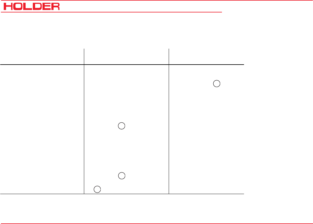
Driver's license classes (Germany only)
Tractors for farming and forestry (also with imple-
ments)
Maximum Speed
(dependent on type) Maximum Total Weight Driver's License Class
(Minimum Requirements)
Former Driver's License
Class
up to 32 km/h no limitation B, L, T 1, 1a, 1b, 2, 3, 4, 5
over 32 km/h up to 3.5 tons B
T: 60 km/h, under 18 years
only 40 km/h
2, 3
over 3.5 tons
to 7.5 tons
C1
T: 60 km/h, under 18 years
only 40 km/h
2, 3

C 9700 ... C 9.88 H
Operating Instructions
8145 052
Instructions for Operation
Single-axle Trailers or Two-axle Trailers with an Axle Base of up to max. 1 m
25
25
25
25
Maximum Total Weight Driver's License Class
(Minimum Requirements)
Former Driver's License
Class
up to 750 kg trailer weight B, C1, C, T
L: only with additional
sign and maximum tractor
speed of 25 km/h
(depending on type)
1, 1a, 1b, 2, 3, 4, 5
over 750 kg trailer weight BE, C1E, CE, T
B, C1, C: only up to
3.5 tons adm. total weight of
the combination and adm.
total weight of trailers
≤ dead weight of tractor;
otherwise:
C1E: only up to 12 tons adm.
total weight of combination
and adm. total weight of
trailer ≤ dead weight of
tractor; otherwise:
L:
1, 1a, 1b, 2, 3, 4, 5

145 052 9
C 9700 ... C 9.88 H Instructions for Operation
Operating Instructions
Multiple-axle Trailers and Two-axle Trailers with an Axle Base over 1 m
25
25
25
25
25
Maximum Total Weight Driver's License Class
(Minimum Requirements)
Former Driver's License
Class
up to 750 kg trailer weight B, C1, C, T
L: only with additional
sign and maximum tractor
speed of 25 km/h
(depending on type)
2, 3
over 750 kg trailer weight
up to 3.5 tons Maximum Total
Weight
up to 12 tons Maximum Total
Weight
BE, C1E, CE, T
B, C1, C: only up to
3.5 tons adm. total weight of
the combination and adm.
total weight of trailers
≤ dead weight of tractor;
otherwise:
C1E: only up to 12 tons adm.
total weight of combination
and adm. total weight of
trailer ≤ dead weight of
tractor; otherwise:
L:
2, 3
1, 1a, 1b, 4, 5:
in each case
C 9700 ... C 9.88 H
Operating Instructions
10 145 052
Instructions for Operation
Two Trailers behind Tractors for Farming and Forestry
25
25
25
25
Maximum Total Weight Driver's License Class
(Minimum Requirements)
Former Driver's License
Class
up to 3.5 Maximum Total
Weight
up to 12 Maximum Total
Weight
BE, C1E, CE, T
B, C1, C
in each case only up to
3.5 tons adm. total weight of
the combination and adm.
total weight of trailers
≤ dead weight of tractor;
otherwise:
C1E:
only up to 12 tons adm. total
weight of combination and
adm. total weight of trailer ≤
dead weight of tractor;
otherwise:
L:
2, 3
1, 1a, 1b, 4, 5,

145 052 11
C 9700 ... C 9.88 H Instructions for Operation
Operating Instructions
Safety
General Notes on Safety
• Observe the VSG 3.1 (German regulations for safety
and health protection).
• Do not allow children under 16 to use the tractor.
• When using the public highway, respect the highway
code.
• Do not allow anyone to stand around where they might
get hurt.
• Do not run the engine in enclosed spaces.
• Exercise extreme caution when handling fuels - there
is a high risk of fire.
• Exercise extreme caution when handling fuels and
oils; these can be poisonous and caustic.
• To prevent the danger of fire, keep the tractor and
implements clean.
• Observe the warning notices and symbols on your
tractor.
Working Clothes
• Only wear snugly fitting clothing when working with
the tractor.
• If necessary, wear suitable headwear to keep loose
hairs and pigtails from being caught in rotating parts.
• Do not wear any jewellery and similar objects, eg
rings, when working with the tractor.
Safety Notes for Later Installations
The tractor has electronic components whose proper
functioning can be influenced by the electromagnetic
emissions of other equipment. These influences can
endanger persons if the following notes on safety are not
observed.
• Have your equipment installed only by an authorized
workshop.
• Before the installation of electric or electronic equip-
ment connected to the tractor's electrical system,
check if these installations can interfere with the
tractor's electronic system or other system compon-
ents.

C 9700 ... C 9.88 H
Operating Instructions
12 145 052
Instructions for Operation
• The installed equipment must conform to the applica-
ble EMC directive 89/336/EU and carry the CE
symbol.
• If you must install a mobile communications system
(or have it installed) (eg radio, mobile telephone), the
following requirements must be met:
- Only approved equipment (eg BTZ approval in Germa-
ny) may be installed.
- The equipment must be installed permanently.
- The operation of portable or mobile equipment inside
the vehicle is only allowed if connected to a perma-
nently installed external antenna.
- The transmitting section must be installed away from
the tractor's electronic system.
- When installing the antenna, install it properly and
with a good connection vehicle ground.
- Do not exceed the maximum permissible current
rating of the wiring according to the installation in-
structions of the equipment manufacturer.
Safety Instructions for Handling Fuels and
Oils
Gear Oil, Engine Oil, Diesel Fuel
Do not eat, drink or smoke when working with
the product. Prolonged intensive contact may
cause degreasing and irritation of the skin.
Wash skin with soap and water, use skin care
products. If required, wear protective gear.
Change soaked clothes and shoes immedi-
ately. If vapour or mist was inhaled, breathe
fresh air. Consult a doctor if the complaint
persists. After contact with the eyes, rinse
the eyes thoroughly with water (at least 10
minutes), then consult an eye doctor. If swal-
lowed, do not force to vomit, but consult a
doctor. Danger of slipping on the spilled prod-
uct, especially in connection with water.
Oils can contaminate water. Always keep
them in approved containers. Avoid spilling
oils. Remove spilled fluids at once with an oil
binding agent and dispose of in accordance
with laws and regulations. Discard drained
fluids as specified. Observe all applicable laws
and regulations. Oils are inflammable. Do not
145 052 13
C 9700 ... C 9.88 H Instructions for Operation
Operating Instructions
let them come in contact with hot engine parts
as fire can result.
Hydraulic Oil, Brake Fluid
During tractor operation, these fluids are under
pressure and a health hazard. Do not spill these
fluids! Remove any spilled fluid at once with an
oil binding agent and discard as specified. Dis-
pose of old fluids as specified and follow the
applicable laws and regulations. Do not allow
them to come in contact with hot engine parts
as fire can result. Danger of fire!
Avoid contact with the skin. Avoid the inhalation
of spray fog. The penetration of the fluids into
the skin is especially dangerous if the fluids
are under high pressure and escape from the
hydraulic system through leaks. Seek medical
aid at once in case of such injuries.
If injuries cannot be excluded, use suitable
protectors (for example, protective gloves,
glasses and skin protection and care creams).
Battery Acid
Battery acid contains dissolved sulphuric
acid. This acid is poisonous and caustic. When
working with battery acid, always wear
protective clothing and eye protectors. Do not
allow acid to contact clothing, skin or eyes.
In case of contact, wash directly with ample
clean water. If personal injuries exist, seek
medical aid at once. Neutralize spilled battery
acid immediately.
Discard the old battery fluid as specified.
Observe laws and regulations.
Emissions
Exhaust Gases
During operation, the engine emits exhaust
gases into the environment. The exhaust gas
mainly consists of water vapour, carbon
dioxide (CO2), carbon monoxide (CO),
hydrocarbon (CH), nitrogen oxide (NOX) and
soot. The components CO, CH and NOX are
poisonous or hazardous to health and should
not be inhaled in high concentrations. Soot is
a carcinogenic material; particularly the

C 9700 ... C 9.88 H
Operating Instructions
14 145 052
Instructions for Operation
particles in the exhaust gases can cause
cancer. For this reason the engine may not
be operated in enclosed spaces.
Heat
The exhaust gases are very hot and can ignite
inflammable material. The exhaust gas pipe
should therefore be kept away from ignitable
material.
Battery
During charging, the battery produces a mix-
ture of oxygen and hydrocarbon (detonating
gas). This mixture of gases is explosive and
may not be ignited. The risk of explosion can
be avoided with proper ventilation and keep-
ing naked flames away. Observe the safety
rules when handling the battery.

145 052 15
C 9700 ... C 9.88 H Operating Instructions
Technical Data
Model Variants
Model Transmission Type of Drive Type of Engine Engine Performance
C 9700 Mechanical Reversing
Gearbox Mechanical BF4M1011 53.5 kW 72 HP (DIN)
C 9700 H Hydrostatic transmission Hydrostatic BF4M1011 53.5 kW 72 HP (DIN)
C 9800 H Hydrostatic transmission DUAL DRIVE* BF4M1011F 61 kW 83 HP (DIN)
C 9.72 Mechanical Reversing
Gearbox Mechanical BF4M1011 53.5 kW 72 HP (DIN)
C 9.72 H Hydrostatic transmission Hydrostatic BF4M1011 53.5 kW 72 HP (DIN)
C 9.83 H Hydrostatic transmission DUAL DRIVE* BF4M1011F 61 kW 83 HP (DIN)
C 9.78 H Hydrostatic transmission Hydrostatic BF4M2011 57 kW 78 HP (DIN)
C 9.88 H Hydrostatic transmission DUAL DRIVE* BF4M2011F 65 kW 88 HP (DIN)
* mechanical + hydrostatic
^
=
^
=
^
=
^
=
^
=
^
=
^
=
^
=
C 9700 ... C 9.88 H
Operating Instructions
16 145 052
Technical data
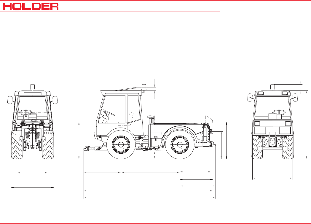
Tractor Dimensions
Sketch
g
b
d
c100
(3,9")
200
(7,8")
3980-4100 (156,5-161,4")
3900-4020 (153,5-158,3")
1110
1030
970
(43,1")
(40,5")
(38,2")
1827 (72")1040-1160 (40,9-45,6") 1090
(Cab for 1 person)
1250
(42,9")
(49,3")
(Cab for 2 persons)
f
a
e
Bild_194
Data in brackets are American dimensions

Operating Instructions
145 052 17
C 9700 ... C 9.88 H Technical data
Trailer Coupling
Tires Type Overall Height Avg. Height of
Seat
Ground
Clearance
Lowest Position Highest Position Height of Body
a
mm (Inches)
b
mm (Inches)
c
mm (Inches)
d
mm (Inches)
d
mm (Inches)
g
mm (Inches)
10.5-18 MPT S 524-31-6 2130 (83.8) 1050 (41.3) 230 (9) 575 (22.4) 975 (38.2) 1130 (44.5)
10.5-18 MPT 524-31-1 2130 (83.8) 1050 (41.3) 230 (9) 575 (22.4) 975 (38.2) 1130 (44.5)
36x13.50-15 524-31-8 2100 (82.5) 1020 (40.1) 200 (7.9) 545 (21.3) 945 (37.1) 1095 (43.1)
400/60-15.5524-31-5 2095 (82.3) 1030 (40.5) 195 (7.5) 540 (21.2) 940 (37) 1095 (43.1)
33x12,50-R15 524-31-7 2090 (82.2) 1020 (40.1) 190 (7.3) 535 (21.0) 935 (36.6) 1090 (42.9)
33/18LL-16.1 524-31-9 2090 (82.2) 1020 (40.1) 190 (7.3) 535 (21.0) 935 (36.6) 1090 (42.9)
33x12.50-15 524-31-4 2075 (81.4) 1010 (39.7) 180 (7) 525 (20.6) 925 (36.3) 1075 (42.3)
33x15.50-15 524-31-3 2075 (81.4) 1010 (39.7) 180 (7) 525 (20.6) 925 (36.3) 1075 (42.3)
31x15.50-15 524-31-2 2065 (81.1) 980 (38.6) 165 (6.4) 510 (20) 910 (35.8) 1060 (41.7)
Table of Dimensions

C 9700 ... C 9.88 H
Operating Instructions
18 145 052
Technical data
Tires
Min. Turning
Radius to DIN
7020
(measured at
outermost
point of
vehicle)
Normal Track Width
(Flange size 1034)With Hub Spacers
Type 5234-80= 45 mm Type 526-34-70= 80 mm
Track Width e Overall Width f Track Width e Overall Width f Track Width e Overall Width f
mmin.-
mm
max.-
mm
min.-
mm
max.-
mm
min.-
mm
max.-
mm
min.-
mm
max.-
mm
min.-
mm
max.-
mm
min.-
mm
max.-
mm
36x13.50-15 7.28 m
f. track w. 1084 - 1084 - 1439 1090 1174 1445 1529 1160 1244 1515 1599
10.5-18 MPT S 7.10 m
f. track w. 960 960 1124 1230 1394 1124 1140 1320 1484 1120 1284 1390 1554
10.5-18 MPT 7.14 m
f. track w. 1034 1034 1050 1304 1320 1050 1214 1394 1410 1194 1210 1464 1480
400/60-15.5 7.30 m
f. track w. 1070 - 1070 - 1470 1106 1160 1506 1560 1176 1230 1576 1630
33x12.50 R15 7.15 m
f. track w. 1000 1000 1084 1320 1404 1090 1174 1410 1494 1160 1244 1480 1564
33x12.50-15 7.15 m
f. track w. 1000 1000 1084 1320 1404 1090 1174 1410 1494 1160 1244 1480 1564
33x15.50-15 7.24 m
f. track w. 1124 *• 992 1124 * 1382 1514 1052 1214 1442 1604 1122 1284 1512 1674
33/18LL-16.1 7.45 m
f. track w. 1164 - 1164 - 1636 - 1254 - 1726 - - - -
31x15.50-15 7.30 m
f. track w. 1124 *• 962 1124 * 1332 1494 1052 1214 1422 1584 1122 1284 1492 1654
*Snow chains not possible
* With track spacer type 526-34-75 (15 mm per wheel)
Track Widths

Operating Instructions
145 052 19
C 9700 ... C 9.88 H Technical data
All Tractors Weight in kg
Permissible total weight 4500 kg (9920.6 LBS)
Permissible load on front axle *2660 kg - 2700 kg
(5864 LBS - 5952 LBS)
Permissible load on rear axle *2660 kg - 2700 kg
(5864 LBS - 5952 LBS)
Permissible supporting load on
trailer hitch 800 kg (1764 LBS)
* With 33x12.50 R15 tires
Accessories Total Front Rear
Creep speed gear 13 kg
(28.6 LBS)
10 kg
(22 LBS)
3 kg
(6.6 LBS)
Rear lift 77 kg
(169.7 LBS)
-25 kg
(-55 LBS)
102 kg
(224.8 LBS)
Loading platform 75 kg
(165.3 LBS)
0 k g
(0 LBS)
75 kg
(165.3 LBS)
Weights w/o loading platform and rear lift
Tires 36x13.5-15 10.5-18 MPT
400/60-15.5 33x12.50 R15 33x12.50-15 31x15.50-15
33x15.50-15 33/18LL-16.1
Empty weight (incl.
driver 75 kg)
C9700
C9.72
C9700H
C9800H
C9.72H
C9.78H
C9.83H
C9.88H
C9700
C9.72
C9700H
C9800H
C9.72H
C9.78H
C9.83H
C9.88H
C9700
C9.72
C9700H
C9800H
C9.72H
C9.78H
C9.83H
C9.88H
C9700
C9.72
C9700H
C9800H
C9.72H
C9.78H
C9.83H
C9.88H
C9700
C9.72
C9700H
C9800H
C9.72H
C9.78H
C9.83H
C9.88H
C9700
C9.72
C9700H
C9800H
C9.72H
C9.78H
C9.83H
C9.88H
Total: kg 2430
(5351)
2620
5776)
2440
(5319)
2630
(5198)
2390
(5269)
2580
(5687.8)
2380
(5246.9)
2570
(5665.8)
2410
(5313.1)
2600
(5732)
2470
(5445.4)
2660
(5864.2)
Front: kg 1275
(2810.8)
1390
(3064.4)
1280
(2821.8)
1395
3015)
1255
(2766.7)
1370
(3020.3)
1250
(2755.7)
1365
(3009.3)
1265
(2788.8)
1380
(3042.3)
1295
(2855)
1410
(3108.5)
Rear: kg 1155
(2546.3)
1230
(2711.6)
1160
(2551.3)
1235
(2122.6)
1135
(2502)
1210
(2667.5)
1130
(2491.2)
1205
(2656.5)
1145
(2524.3)
1220
(2689.6)
1175
(2590.4)
1250
(2755.7)
Weights

C 9700 ... C 9.88 H
Operating Instructions
20 145 052
Technical data
Type of Tire Ply Profile Tube Inflation Pressure Wheel Weights
Type Weight
10.5-18 MPT S 6 Cleat profile yes 1.5 bar (22 PSI) 524-34-1 approx. 45 kg (100 LBS)
10.5-18 MPT 6 Cleat profile yes 1.5 bar (22 PSI) 524-34-1 approx. 45 kg (100 LBS)
31x15.50-15 8 Profile no 2.0 bar (14-29 PSI) 524-34-1 approx. 45 kg (100 LBS)
33x15.50-15 4 Profile no 1.0 bar (14.7 PSI) 524-34-1 approx. 45 kg (100 LBS)
33x12.50-15 6/8 (M+S)/Profile no 1.4 bar (20 PSI) 524-34-1 approx. 45 kg (100 LBS)
33x12.50-R15 6 M + S no 1.6 bar (23 PSI) 524-34-1 approx. 45 kg (100 LBS)
36x13.50-15 4 Lawn no 1.0 bar (14.7 PSI) 524-34-1 approx. 45 kg (100 LBS)
400/60-15.5 6 Profile yes 1.8 bar (26 PSI) 524-34-1 approx. 45 kg (100 LBS)
33/18LL-16.1 10 Lawn no 1.2 bar (17 PSI) 524-34-1 approx. 45 kg (100 LBS)
Tires
NOTE: Observe prescribed inflation pressure with maximum axle load and when driving on roads.

Operating Instructions
145 052 21
C 9700 ... C 9.88 H Technical data
Engine Specifications
C 9700/9.72
C 9700/9.72H C 9800/9.73H C 9.78H C 9.88H
Manufacturer Deutz AG Deutz AG Deutz AG Deutz AG
Type BF4M1011 BF4M1011F BF4M2011 BF4M2011
Mode of operation Four-stroke Diesel Four-stroke Diesel Four-stroke Diesel Four-stroke Diesel
Number of cylinders 4 4 4 4
Cubic capacity 2914 2914 3108 3108
Fuel consumption 223g/KW-h at
1500-1750 rpm
222g/KW-h
at 1750-1850 rpm
216g/KW-h
at 1750-1850 rpm
216g/KW-h
at 1550-1650 rpm
Rated speed 2500 rpm 2600 rpm 2500 rpm 2800 rpm
Maximum idling speed 2600 rpm 2750 rpm 2750 rpm 3050 rpm
Minimum idling speed 900 rpm 900 rpm 900 rpm 900 rpm
Power at n=2800 rpm 53.5 KW (72 HP) 61 KW (83 HP) 57 KW (78 HP) 65 KW (88 HP)

C 9700 ... C 9.88 H
Operating Instructions
22 145 052
Technical data
Transmission Unit Gearbox Hydrosta-
tic Drive
Hydrosta-
tic Drive
Hydrosta-
tic Drive
Dual
Drive
Dual
Drive
Dual
Drive
Engine Output kW 53.5 53.5
57 61 65 53.5
57 61 65
Engine speed rpm 2500 2500 2600 2800 2500 2600 2800
Tires Type
36x13.50-15 524-31-8 km/h 36.8 30.8 32.0 34.4 38.4 39.9 43.0
10.5-18 MPT 524-31-1/-6 km/h 35.9 30.1 31.3 33.7 37.6 39.1 42.1
400/60-15.5 524-31-5 km/h 34.1 28.6 29.7 32.0 35.7 37.1 40.0
33x12.50 R15 524-31-7 km/h 33.3 27.9 29.0 31.2 34.8 36.2 39.0
33x12.50-15 524-31-4 km/h 32.4 27.2 28.3 30.4 33.9 35.3 38.0
33x15.50-15 524-31-3 km/h 32.4 27.2 28.3 30.4 33.9 35.3 38.0
33/18LL-16.1 524-31-9 km/h 31.8 26.7 27.8 29.9 33.3 34.7 37.3
31x15.50-15 524-31-2 km/h 30.5 25.1 26.1 28.1 31.3 32.6 35.1
Theoretical Driving Speeds

Operating Instructions
145 052 23
C 9700 ... C 9.88 H Technical data
Assembly Suppl. Information Description
Mechanical gearbox 16 forward gears/16 reverse gears with planetary axles
Hydrostatic drive Infinitely variable driving speed, 2 mechanical speed ranges
Power take-offs 2 PTOs (front and rear) Rotating Direction: clockwise when looking at
end of shaft
- RPM, front 540 rpm at 2200 engine rpm, 1000 rpm at 2390 engine rpm
- RPM, rear 1000 rpm at 2360 engine rpm
- Wedge shaft profile 1 3/8 " (6) DIN 9611
PTO clutch Multiple disk wet clutch
Differential lock Acts simultaneously on front and rear axles
Fuel system
Fuel tank Diesel fuel 86 l (22.7 USGAL.)
Technical Data/Filling Quantities

C 9700 ... C 9.88 H
Operating Instructions
24 145 052
Technical data
Assembly Suppl. Information Description
Steering
- Type Hydrostatic with 2 double-acting steering rams
- Steering valve Orbitrol OSPC 125 LS
Brakes
- Service brake Multiple-disk brakes, wet, acting on all 4 wheels
- Activation Hydraulic
- Parking brake Multiple-disk brakes, wet, acting on all 4 wheels
- Activation Mechanical
Trailer hitch
- Make Cramer, height-adjustable
Front lift
- Make 3-point, upper link adjustable
- Mounting Category I and II
- Lifting power 27000 N (measured at installation points)
- Cylinders 2 double-acting cylinders

Operating Instructions
145 052 25
C 9700 ... C 9.88 H Technical data
Assembly Suppl.
Information Description
Rear lift
- Model HOLDER 3-point standard
- Mounting Category I and II
- Lifting power 15700 N (at installation points)
- Cylinders 2 double-acting cylinders
Drive Hydraulics
Variable pump Hydromatik
- Model A11 VG 50 EP / A4 VG 40 EP
- Flow rate 160 l/min (42 GAL/MIN)
- Operating pressure 300 bar (4410) (max. 350 bar (5145)) / 380 bar (5586) (max. 430 bar (6320))
Variable motor Hydromatik
- Model A6 VM 55 EP
- Displacement 26.1 - 55 cm3/rev
Hydraulic oil tank 19 l (5.02 GAL.)

C 9700 ... C 9.88 H
Operating Instructions
26 145 052
Technical data
Assembly Suppl. Information Description
Hydraulics for implements
(with steering)
Pump Sundstrand
- Make -
- Flow rate 17 cm3/rev (42.5 l/min at 2500 engine rpm)
- Operating pressure 180 -190 bar
Hydraulic oil tank 22 l (5.8 GAL.)
Electrical System
- Operating voltage 12 VDC
- Battery 12 V / 88 Ah
- A/C alternator 14 V / 60 A
- Starter 12 V / 2.4 kW
Whole Vehicle
- Ambient temperature range - 30° to + 50°C

Operating Instructions
145 052 27
C 9700 ... C 9.88 H Technical data
Noise Level
The tractor emits the following noise level (measured at the
driver's ear) according to EU Standard 77/311/EEC;
measurement according to Appendix II.
Table of Noise Levels and Absorption Rating
Exhaust Gas Identification
The absorption rating is stated on the identification plate.
Model Engine Type Engine Output Noise Level dB(A) Absorption rating
Cabin
open*
Cabin
closed
C 9700 BF4M1011 53.5 kW (72 HP) 79 78 2.1
C 9700 H BF4M1011 53.5 kW (72 HP) 79 78 2.1
C 9800 H BF4M1011F 61 kW (83 HP) 79 78 2.1
C 9.72 BF4M1011 53.5 kW (72 HP) 79 78 2.1
C 9.72 H BF4M1011 53.5 kW (72 HP) 79 78 2.1
C 9.83 H BF4M1011F 61 kW (83 HP) 79 79 2.1
C 9.78 H BF4M2011 57 kW (78 HP) 79 79 1.8
C 9.88 H BF4M2011F 65 kW (88 HP) 79 79 2.0
*Roof vent and side window open
C 9700 ... C 9.88 H
Operating Instructions
28 145 052
12345
6
7
8
9
10
11
12
13
15
14
Description
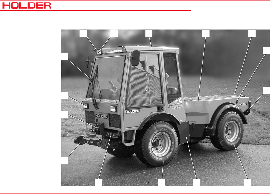
Views of Tractor
Front Left View
1 Turn signal, position
light
2 Headlight, top
3 Driver's cab
4 Dump body (dump)
5 Rear of vehicle
6 Engine oil dipstick
7 Battery isolating switch
8 Rear axle
9 Hydraulic oil tank and
filler neck (drive
hydraulics)
10 Front axle
11 Hydraulic couplings for
implements*
12 Front lift - lower link
support
13 Upper link support
14 Headlight
15 Windshieldwiper /
washer
* Option
Operating Instructions
145 052 29
C 9700 ... C 9.88 H Description
432 5678
9
10
11
12
13
14
15
17
1
16
Bild_002
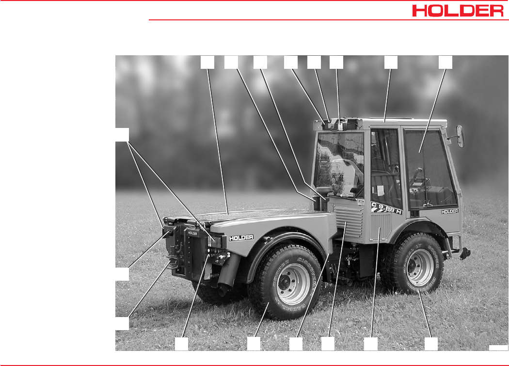
Tractor
Rear Right View
1 Dump Body
2 Fuel filler neck
3 Oil filler neck
for implement hydrau-
lics
4 Intake screen
for fresh air blower
5 Support for
rotating beacon
6 Flood light*
7 Driver's cab
8 Front part of tractor
9 Front axle
10 Intake screen for drive
oil cooler
11 Air vent for drive oil
cooler
12 Oil level gauge for
implement hydraulics
and steering
13 Rear axle
14 Hydraulic couplings for
implements*
15 Trailer hitch
16 Socket for trailer lighting
17 Tail light, LH/RH
* Option

C 9700 ... C 9.88 H
Operating Instructions
30 145 052
Description
* Option
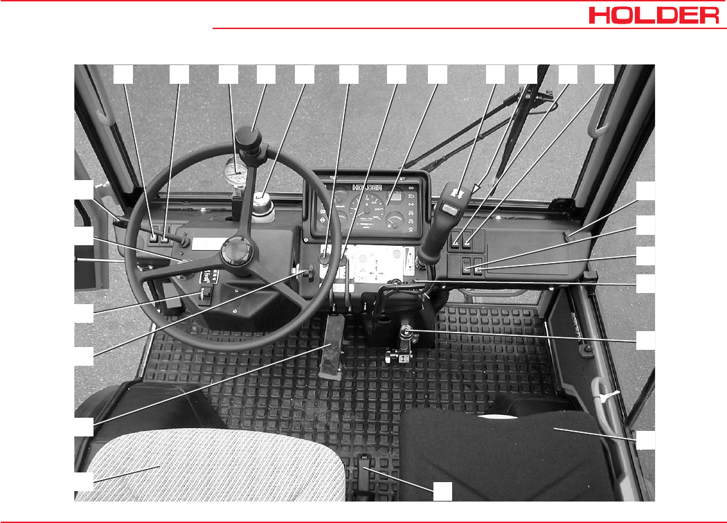
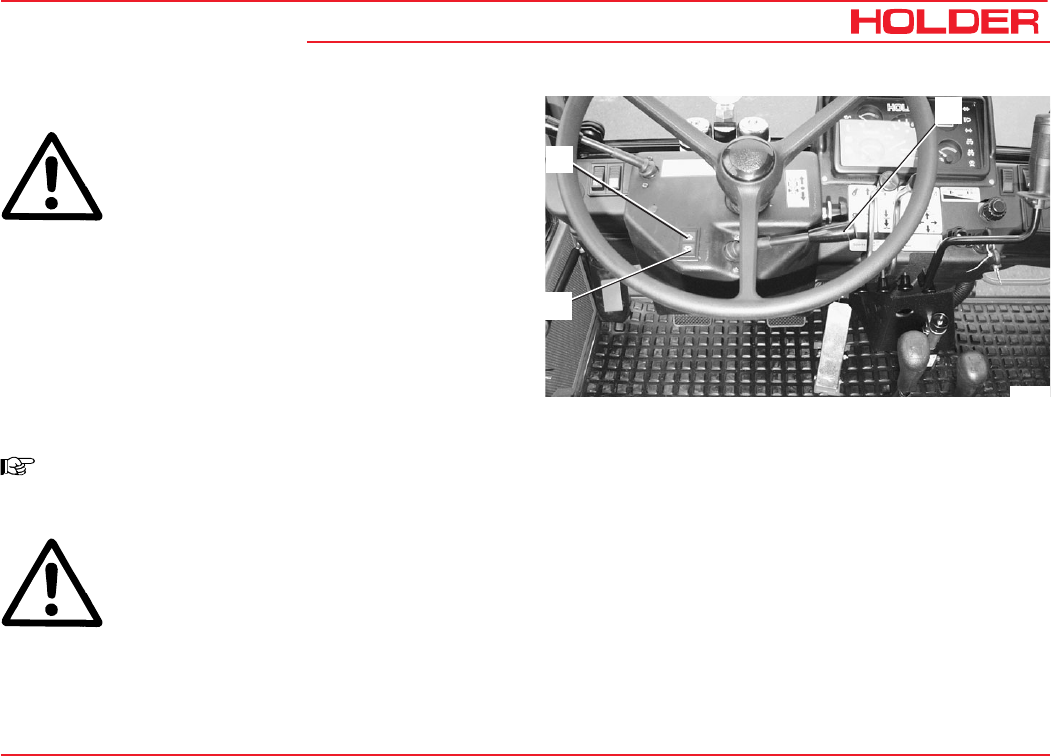
Driver's Station
Operating controls
1 Light switch
2 Differential lock switch
3 Pressure gauge for hydraulic carrier*
4 Steering wheel
5 Brake fluid reservoir
6 Control lever for dump support*
7 Implement* control lever
8 Multi-function display
9 Multi-function lever* (front lift and direction of travel)
10 Digital instrument switch (ground speed in km/h or
PTO rpm)
11 Hazard warning flasher switch
12 Heater fan switch
13 Power Socket
14 Implement lock switch*
15 Tilt lock switch*
16 Preheat/starter switch
17 Hydraulic carrier* control
18 Passenger seat
(water reservoir for windshield washer system is
located under the seat)
19 Parking brake lever
20 Driver's seat
(warning triangle is mounted behind the seat)
21 Accelerator pedal
22 Steering wheel tilt adjustment knob
23 Driving program switch
24 Inch knob for ground speed
25 Turn signal lever
Operating Instructions
145 052 31
C 9700 ... C 9.88 H Description
3
2
1456789 10 11 12
13
14
15
16
17
18
19
22
21
20
24
25
23
C 9700 ... C 9.88 H
Operating Instructions
32 145 052
Description
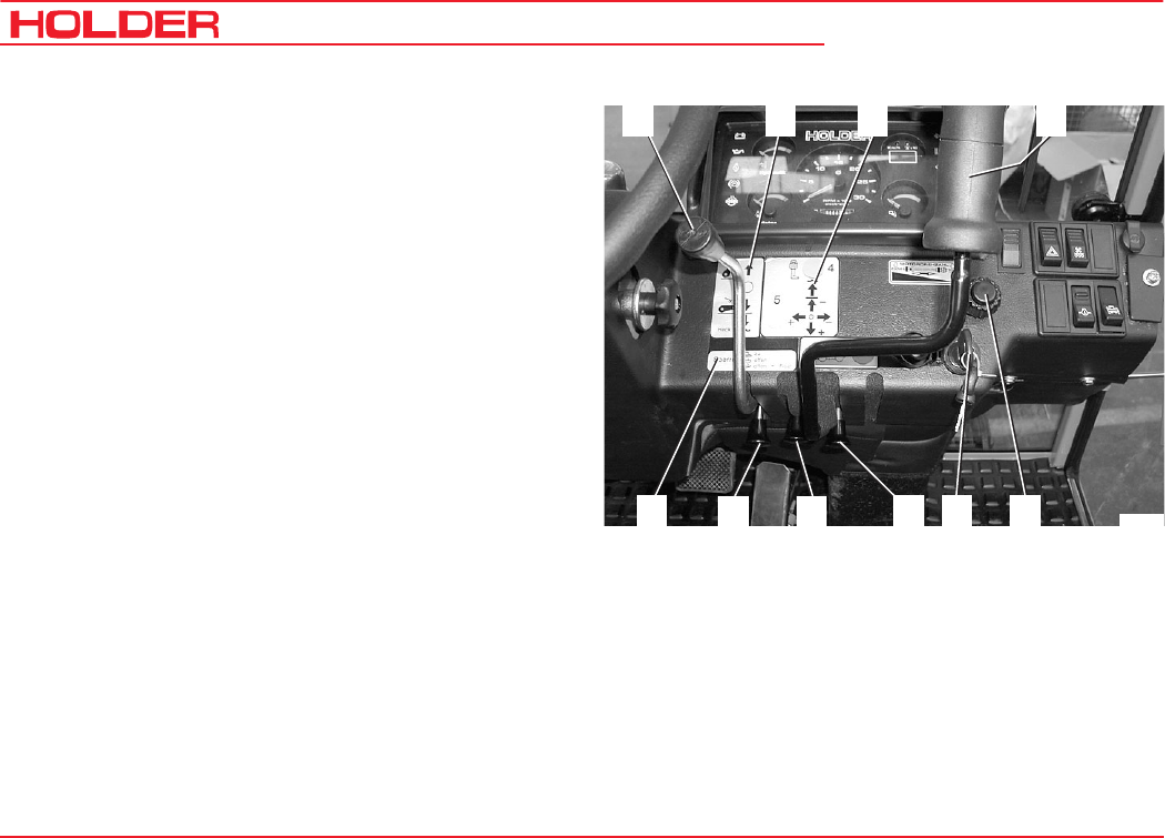
1234
56
7
98
10 Bild_004
* Option
Implement* and Engine Controls (Details)
1 Control lever for dump/rear lift*
2 Control lever functions plate
3 Multi-function lever functions plate
4 Multi-function lever* (front lift and travel direction)
5 Hand throttle
- Outer ring for fine adjustment:
Turn clockwise to decrease rpm
Turn counter-clockwise to increase rpm
- Inner knob for coarse adjustment:
Pull out to increase rpm
Push in to decrease rpm
Push in fast for emergency reset to idling rpm
6 Preheat/starter switch
7 Lock knob for longitudinal motion of multi-function
lever:
- Depressed - locked
- Centre position - free movement
- Pulled out - float position
8 Lock knob for lateral motion of multi-function lever
9 Lock knob for longitudinal motion of control lever
10 Lock knob functions plate
Operating Instructions
145 052 33
C 9700 ... C 9.88 H Description
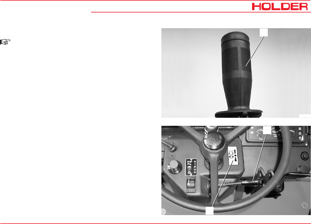
1
Bild_193
2
3
Multi-function Lever
NOTE
Various types of multi-function levers can be
installed.
Multi-function Lever (Variant 1)
1 Multi-function lever without forward reverse selector
lever (Forward-reverse selector installed on instru-
ment board)
2 Forward/reverse selector lever
3 Note plate
Driving direction

C 9700 ... C 9.88 H
Operating Instructions
34 145 052
Description
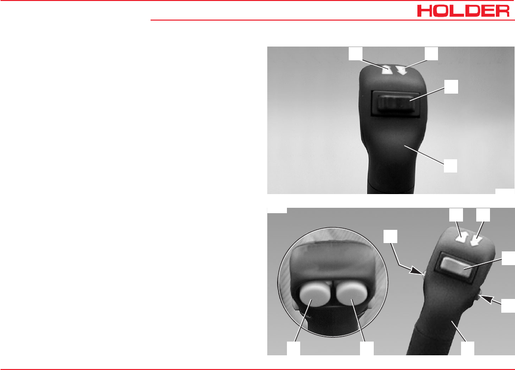
* Option
Multi-function Lever* (Variant 2)
NOTE
The coloured buttons control the function of the
implements attached to the related hydraulic cou-
plings
1 Multi-function lever
2 Blue hydraulic couplings on
3 Blue hydraulic couplings off - float position
4 LED indicator, red or green
5 Functions off
6 LED indicator, red
7 Functions on
8 LED indicator, red
9 LED indicator, red or green
10 Yellow hydraulic couplings, off
11 Green hydraulic couplings off - float position
12 Green hydraulic couplings on
13 Yellow hydraulic couplings on
567
8
9
10
11
12
13
1
2
4
3
blue yellow green
Bild_020
Operating Instructions
145 052 35
C 9700 ... C 9.88 H Description
* Option
87
1
6
2
4
5
3
Bild_068
12
3
Bild_021
4
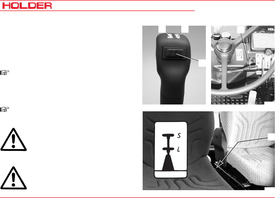
Multi-function Lever* (Variant 3)
1 Forward direction arrow (illuminated if selected)
2 Reverse direction arrow (illuminated if selected)
3 Forward/reverse selector switch (left for forward -
right for reverse)
4 Multi-function lever
Multi-function Lever* (Variant 4)
1 Forward direction arrow (illuminated if selected)
2 Reverse direction arrow (illuminated if selected)
3 Forward/reverse selector switch (left forward - right
reverse)
4 Front lift float position pushbutton
5 Multi-function lever
6 Front lift pushbutton
7 Yellow pushbutton, left (front when looking forward)
(movements at yellow hydraulic couplings on)
8 Yellow pushbutton, right (front when looking forward)
(movements at green hydraulic couplings on)
C 9700 ... C 9.88 H
Operating Instructions
36 145 052
Description
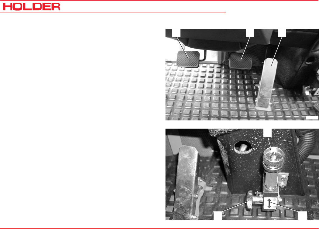
123
Bild_005
1
32
* Option
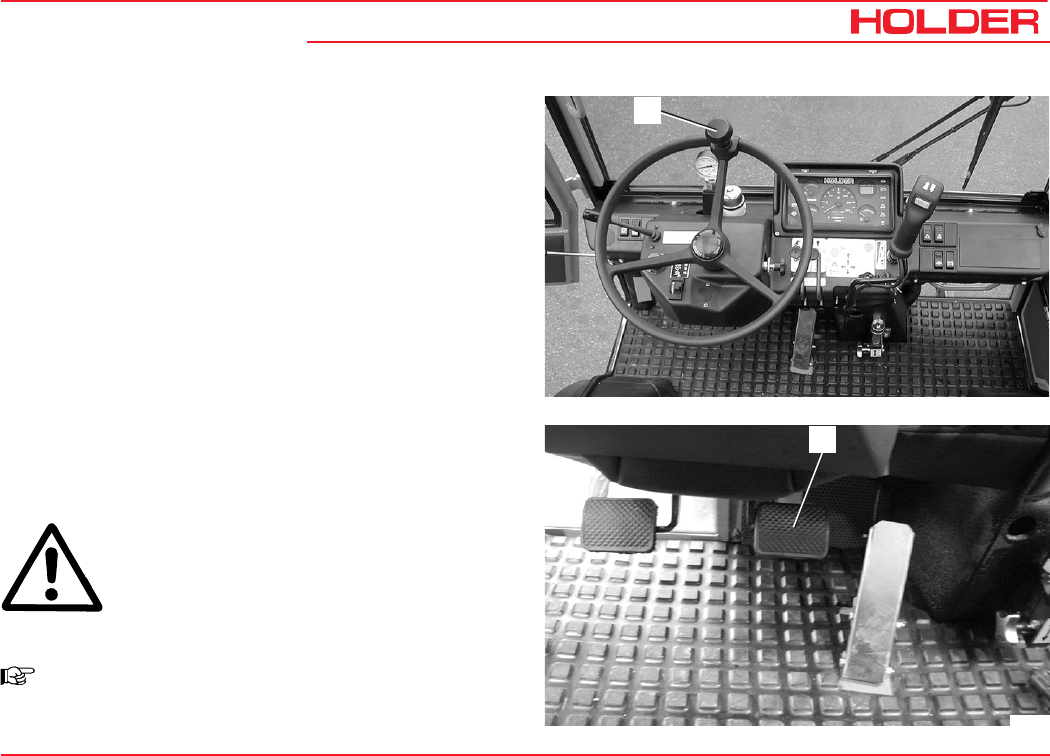
Foot Pedals
1 Inch pedal (clutch pedal if gearbox is fitted)
2 Brake pedal
3 Accelerator pedal
Hydraulic Carrier* Control (Power Lifter)
1 Pressure adjuster
2 ON-OFF label
3 Star knob for turning on/off
Operating Instructions
145 052 37
C 9700 ... C 9.88 H Description
1
4 3
2
1
Bild_069
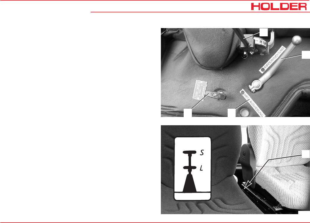
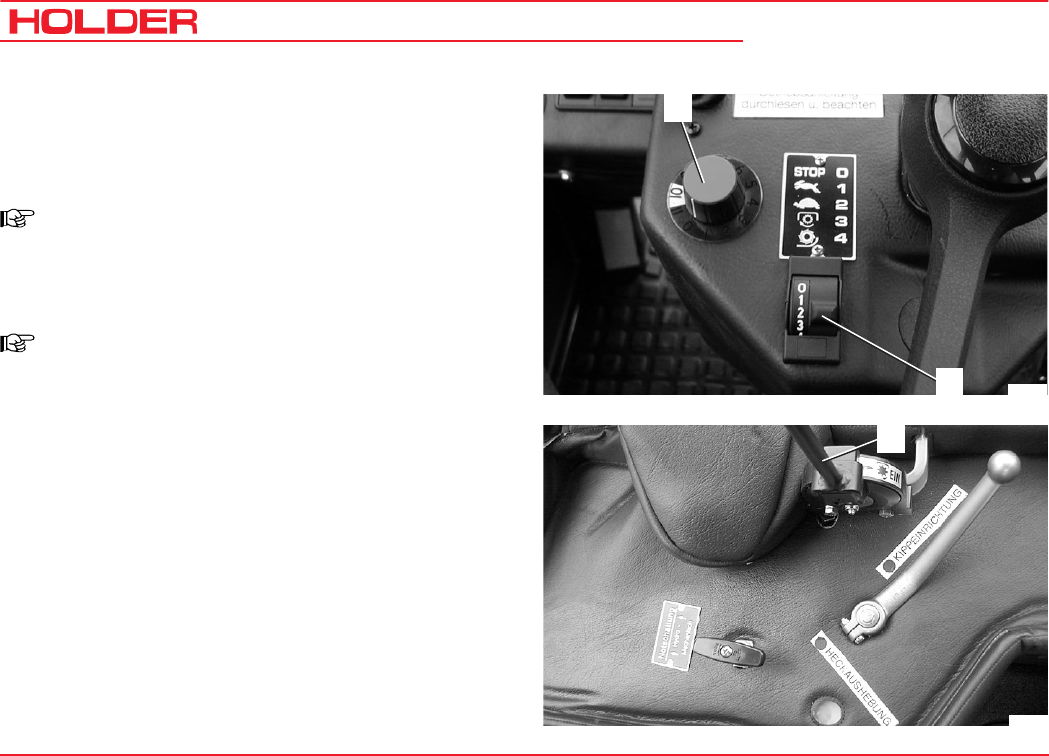
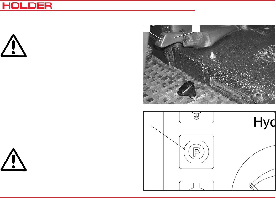
Operating Controls Behind the Seat
1 PTO clutch lever, ON-OFF
2 Device selector lever:
- Position for dump on
3 - Position for rear lift on
4 Emergency start
(Hydrostatic Drive with Dual-Drive only)
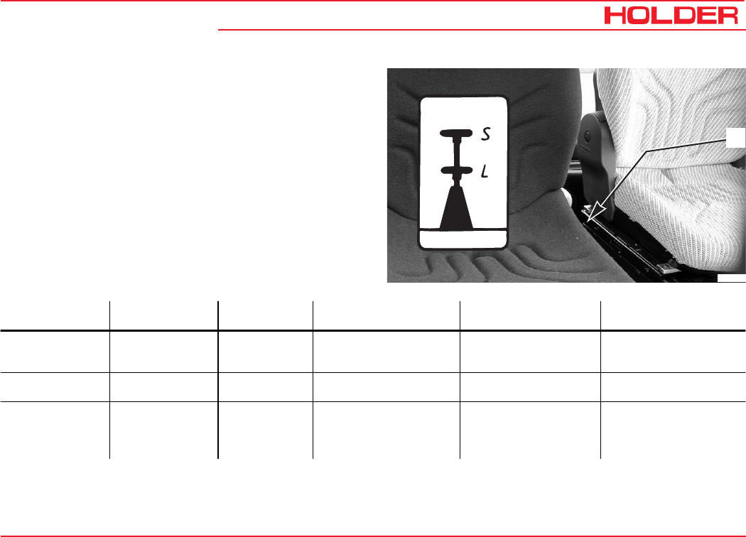
Drive Range Pre-selection Lever between Seats
1 Drive range pre-selection lever
2 Drive range label
- Position S - Fast Driving range
(low tractive force)
- Centre position 0 - Drive off - Towing
- Position L - Slow Working range
(high tractive force)
C 9700 ... C 9.88 H
Operating Instructions
38 145 052
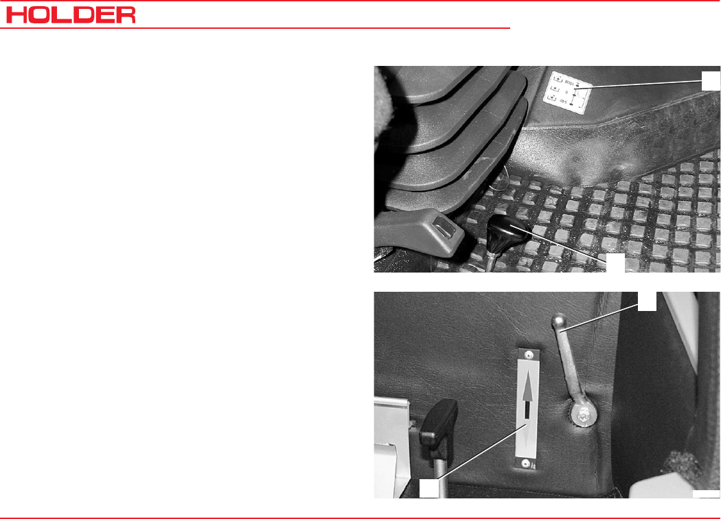
Taking into Service
1
2
1
2Bild_009
Front PTO Selector
1 PTO rpm label
- Top position (up) - 540 rpm
- Centre position - Neutral
- Lower position (down) - 1000 rpm
2 PTO selector lever
Heater
1 Heater temperature control
2 Heating temperature label
- lever up - warmer
- lever down - cooler
Operating Instructions
145 052 39
C 9700 ... C 9.88 H Taking into Service
1
18
2
3
4
5
6
7
17
16
15
14
13
12
891011
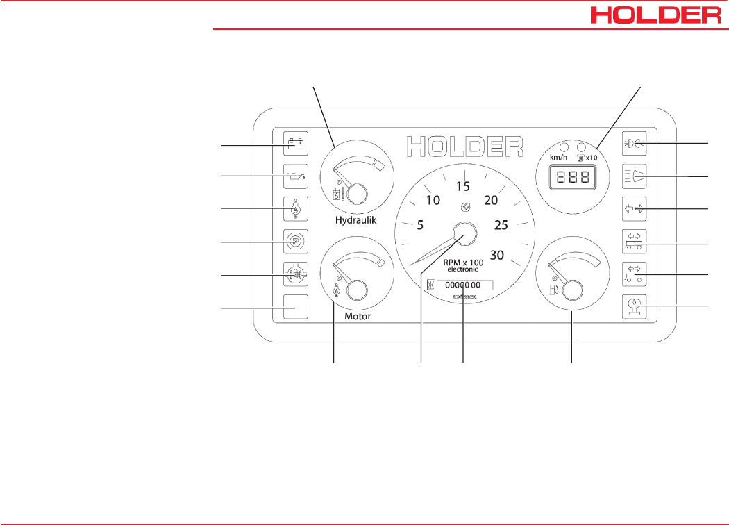
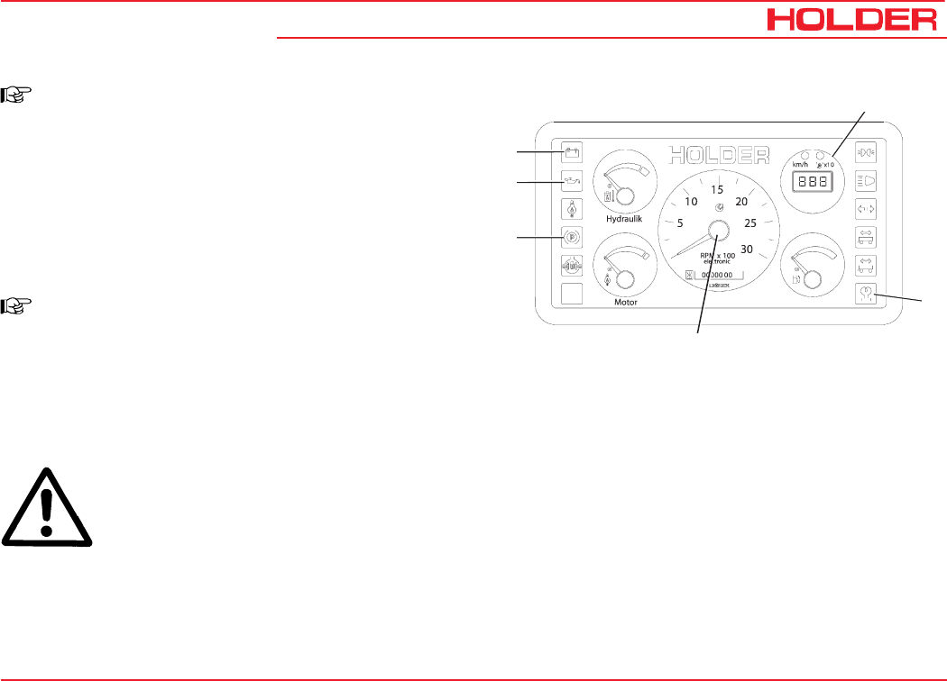
Legend for Multi-function
Display
1 Display for
- Ground speed in km/h or
- PTO rpm x10
2 Position light indicator
3 High beam indicator
4 Turn signal indicator
5 Turn signal indicator
for trailer 1
6 Turn signal indicator
for trailer 2
7 Preheating indicator
8 Fuel gauge
9 Hour meter
10 Tachometer
11 Engine temperature gauge
12 Spare
13 Differential lock engaged
indicator
14 Parking brake engaged indicator
15 Engine oil temperature indicator
16 Engine oil pressure indicator
17 Battery charge indicator
18 Hydraulic oil temperature gauge
C 9700 ... C 9.88 H
Operating Instructions
40 145 052
Description
Bild_17
6
1
2
21
3
Bild_017
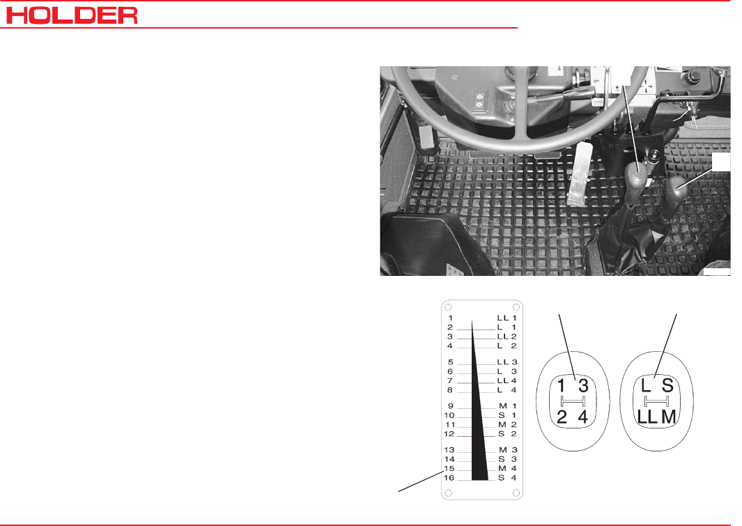
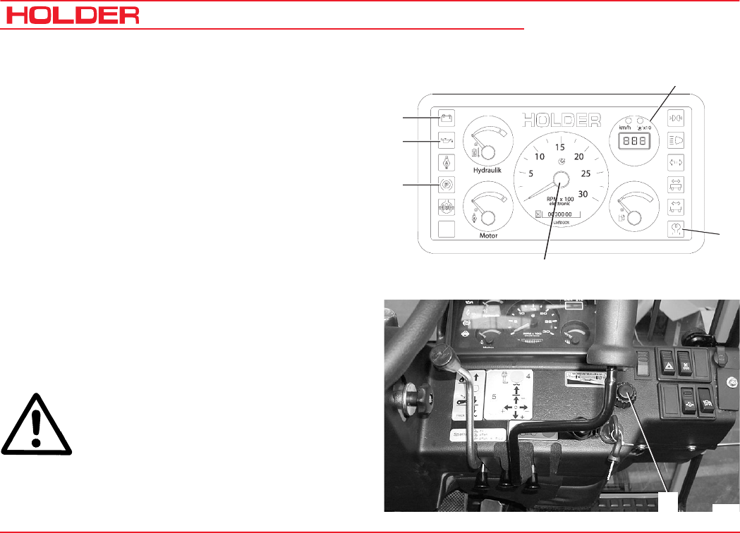
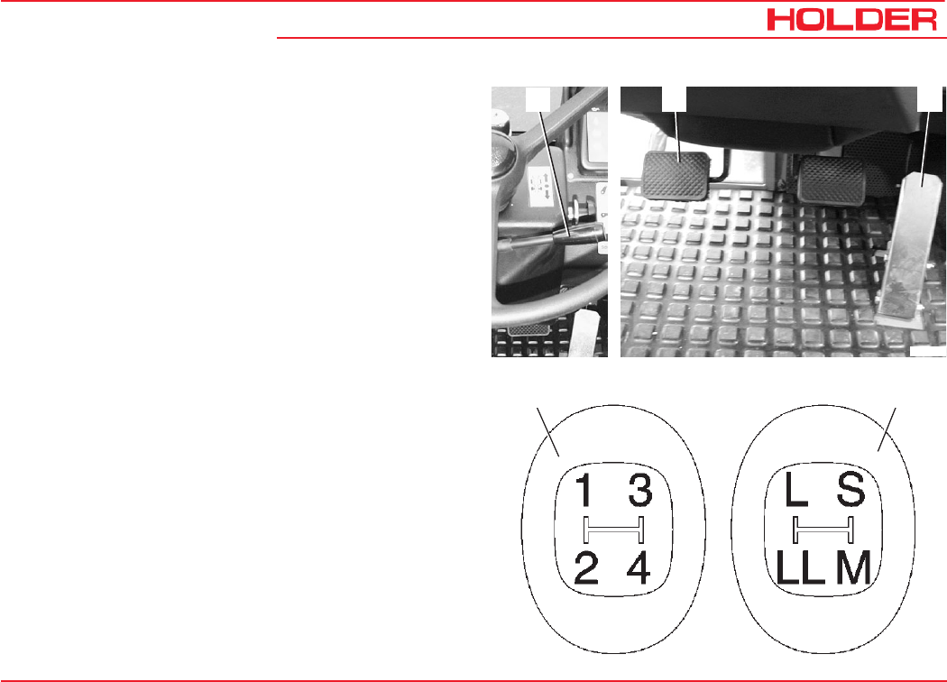
Controls for Mechanical Gearbox
1 Gearshift lever (left looking forward) with 4 synchroni-
zed gears 1-2-3-4
2 Range selector lever (right looking forward)
with 4 speed ranges:
S - Highway driving
M - Medium speed
L- Slow speed
LL - Very slow speed
3 Gearshift label
Operating Instructions
145 052 41
C 9700 ... C 9.88 H Description
1
4
3
2
2
Bild_01
3
134
5
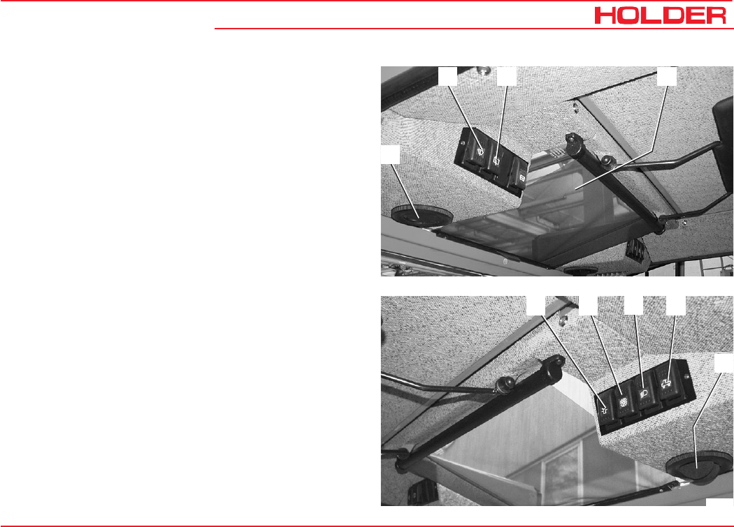
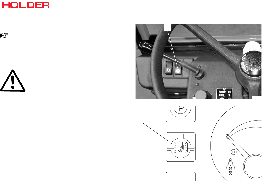
Controls on Cabin Console at Front Left
1 Front wiper/washer switch
2 Rear wiper/washer switch
3 Sun blind
4 Air vent nozzle
Controls on Cabin Console at Front Right
1 Rotating beacon switch
2 Fresh air blower switch, top
3 Headlight switch, top
4 Rear floodlight switch
5 Air vent nozzle
C 9700 ... C 9.88 H
Operating Instructions
42 145 052
Description
12
4
3
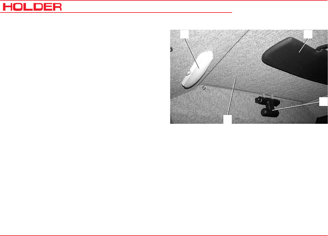
Controls in Cabin at Rear
1 Interior light
2 Sun visor
3 Roof hatch handle
4 Roof hatch
Operating Instructions
145 052 43
C 9700 ... C 9.88 H Description
4
Bild_098
1
2
3
6
5
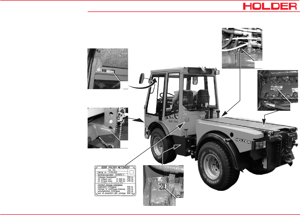
Location of Plates and
Labels
Identification Plates
1 Variable motor type plate
2 Engine type plate
3 Variable pump type plate
4 Machine type plate
5 Chassis Serial Number
(on front RH support
looking forward)
6 Cabin type plate
C 9700 ... C 9.88 H
Operating Instructions
44 145 052
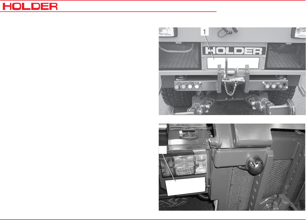
Description
2
Mounting Instructions for License Plate
- Install the front license plate (1) above the upper link
support at the front cabin wall.
- Install the rear license plate (2) at the rear below the
left tail light.

Operating Instructions
145 052 45
C 9700 ... C 9.88 H Description
Assembly Suppl. Information Dimension /Order No./Type
Charcoal filter For cabin ventilation 131667
Pneumatic braking system For trailer operation 526-34-60, 524-34-63
Rear lift 524-51-4
Oil heating element from - 20°C 230 VAC
Hydraulic carrying equipment (power lifter) 524-80-19
Creep speed gearbox with hand lever Super
For mechanical gearbox only 5262-11, 524-62-70
Variable pump for implements 0-100 l /min adjustable 524-80-34
- Pump
- Delivery capacity 0-40 cm³/rev
- Flow rate 0-100 l/min
- Maximum pressure 280 bar
Overview of Options and Variants

C 9700 ... C 9.88 H
Operating Instructions
46 145 052
Description
Assembly Suppl. Information Dimension /Order No./Type
Power hydraulics 75 l/min fixed displacement 524-80-35
- Pump Mounted on drive pump Gear pump
- Delivery capacity 22 cm³/rev
- Flow rate 75 l/min
- Maximum pressure 210 bar
Flow divider I. Circuit 524-80-25
- Pump Standard pump
- Delivery capacity 17 cm³/rev
- Flow rate 0-25 l/min
- Maximum pressure 200 bar
Flow divider II. Circuit 524-80-47
- Pump Tandem pump
- Delivery capacity 14 cm³/rev
- Flow rate 0-25 l/min
- Maximum pressure 200 bar

Operating Instructions
145 052 47
C 9700 ... C 9.88 H Description
Assembly Suppl. Information Dimension /Order No./Type
Circulating oil device rear, uncontrolled 524-80-45
- Pump Tandem pump
- Delivery capacity 14 cm³/rev
- Flow rate 35 l/min
- Maximum pressure 200 bar
Reduction gearbox Reduction of rear PTO rpm to
540 rpm 526-62-1
C 9700 ... C 9.88 H
Operating Instructions
48 145 052
Description
1
3
2
4
5
6
7
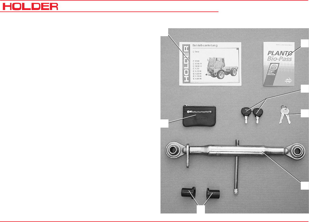
Accessories
The tractor is delivered with the following accessories:
1 Operating Instructions
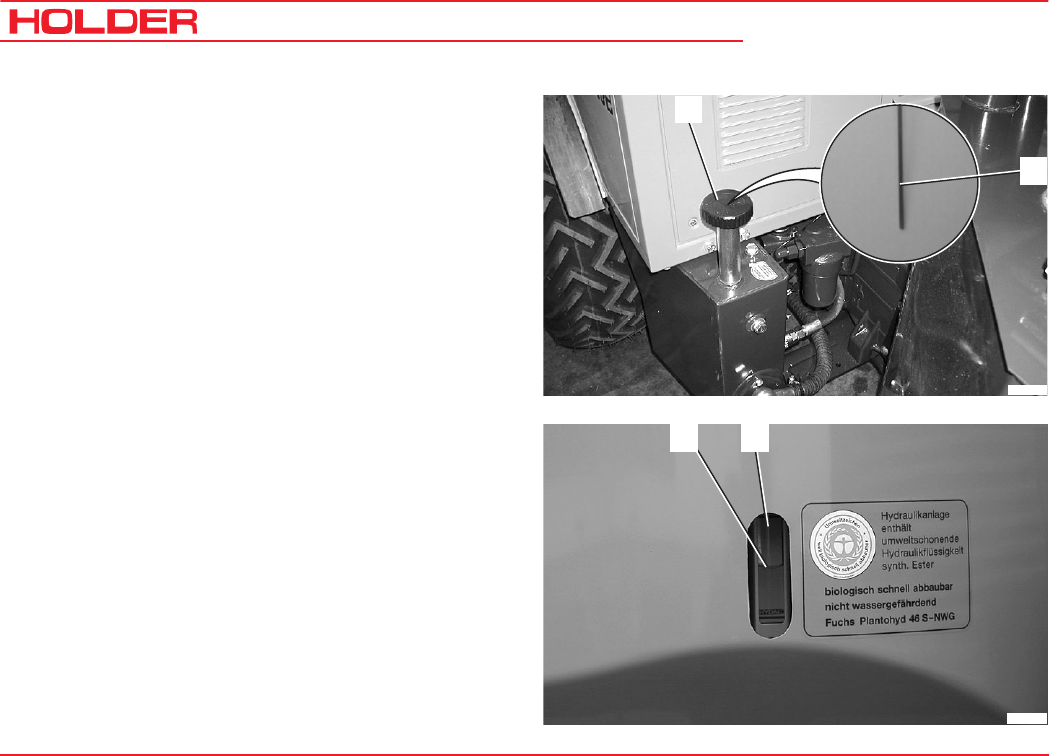
2 Bio-Pass for certification of filling with environment-
friendly hydraulic oil
3 Key holder
4 2 ignition keys
5 4 door keys
6 Upper link
7 2 reducers for category II implements
145 052 49
C 9700 ... C 9.88 H Operating Instructions
Taking into Service
Daily Checks and Activities before Taking
into Service
If damages or defects are found during the following checks,
they must be eliminated before taking the vehicle into
service. Do not operate the tractor before proper repairs are
carried out. Safety and protective devices should not be
removed or disabled. Fixed specified settings may not be
changed.
Before starting work, make yourself familiar with all the
functions and protective devices of the tractor.
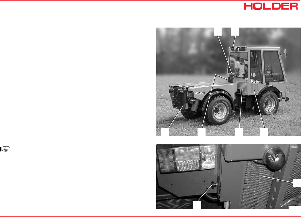
Checking and Cleaning the Cooler and Radiator
Screen Guards
NOTE
- Check if the mud guards (2, 3, 4, 5 and 6)
are clean.
- Clean the mud guards if necessary. The
guard (6) can be pulled out laterally to the
left after releasing the bayonet screw (7)
and then cleaned easily.
- The air intake of the air filter (1) must be
clean.
1 2
34
5
6
Bild_071
7
6
C 9700 ... C 9.88 H
Operating Instructions
50 145 052
Taking into Service
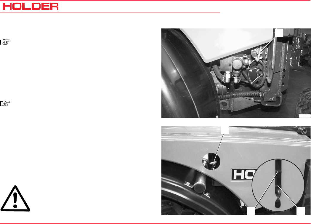
Turning on the Battery Isolating Switch
NOTE
The battery can be switched off completely
with the removable key.
- Insert the key (1) in the battery isolating switch and
set it to the vertical position.
The battery circuit is turned on.
Checking Engine Oil Level
NOTE
Check the engine oil level only when the
tractor is on level ground.
- Let the engine run approx. 2 minutes with the heat
shut-off valve open.
- Stop the engine and pull the oil dipstick (1) out after
approx. 1 minute .
- The oil level should be between the Min (2) and Max
marking (3).
- If necessary, fill oil according to the maintenance
manual.
ATTENTION
Do not fill too much oil.
1
Bild_022
1
2
3
Operating Instructions
145 052 51
C 9700 ... C 9.88 H Taking into Service
Checking the Trailer Hitch (Optional), if required
- Check the trailer hitch for proper condition and wor-
king. Carry out the check according to the instructions
in the section "Operating the Trailer Hitch".
Checking Tire Inflation Pressure
NOTE
Your tractor can be equipped with different
types of tires. The specified inflation pressure
for your tires is given in the table entitled
"Tires" in the technical data section.
- Check the inflation pressure of all four tires. All tires must
have the same pressure. If the pressure is too low, the
rolling resistance increases. This causes an increase in
fuel consumption and tire wear, the driving characteristics
become poorer.
DANGER
If the inflation pressure is too high, the tires
can explode.
- The tires should not be damaged or worn.
- Have damaged tires replaced without delay. Due to the
longer braking distance the risk of an accident is in-
creased.
C 9700 ... C 9.88 H
Operating Instructions
52 145 052
Taking into Service
1
2
Bild_026
2
1
Bild_027
Checking the Drive Hydraulics Oil Level
- Withdraw the oil dipstick (1).
- The oil level must be at the marking (2).
- Top up oil as specified in the maintenance manual.
Checking the Implement Hydraulics Oil Level
- Retract all hydraulic cylinders.
- Check the oil level at the sight glass (2).
The oil level must be at the centre (1) of the sight
glass.
- Top up oil as specified in the maintenance manual.
Operating Instructions
145 052 53
C 9700 ... C 9.88 H Taking into Service
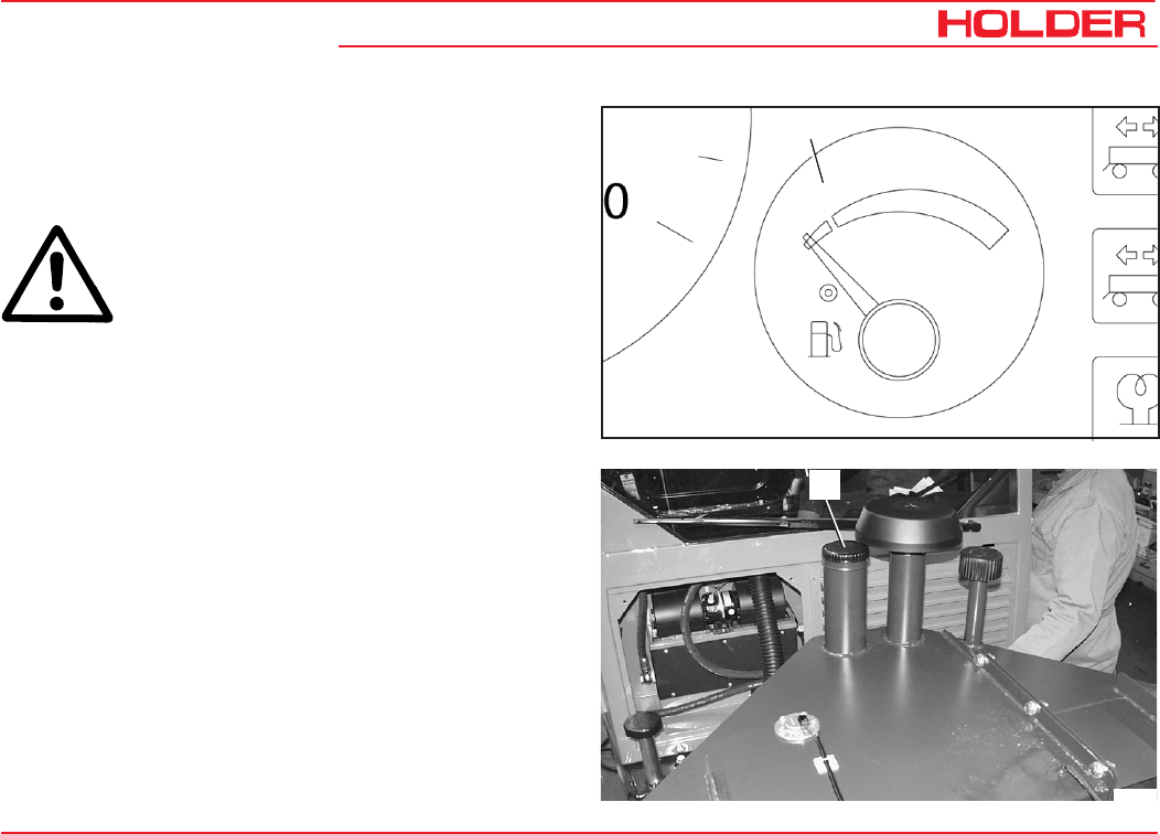
Filling Fuel
- If necessary, read the fuel level (1) on the multi-
function display.
CAUTION
Danger of fire when handling fuels. Turn off
the engine. Do not fill any fuels in the vicinity
of naked flames, ignition sparks or hot engine
parts. Do not smoke during refuelling.
- Remove the fuel tank filler cap (2).
- Top up Diesel fuel as specified in the maintenance
manual.
Filling quantities ............ approx. 86 litres (22.7 USGAL.)
- Refit the filler cap (2).
2
Bild_028
Bild_073
1
C 9700 ... C 9.88 H
Operating Instructions
54 145 052
Taking into Service
1 2
34
Checking the Brake Fluid Level
- Check the brake fluid level at the brake fluid reservoir
(2).
- The brake fluid level must be between the Min and
Max marking at the reservoir.
- Top up the brake fluid as specified in the maintenance
manual.
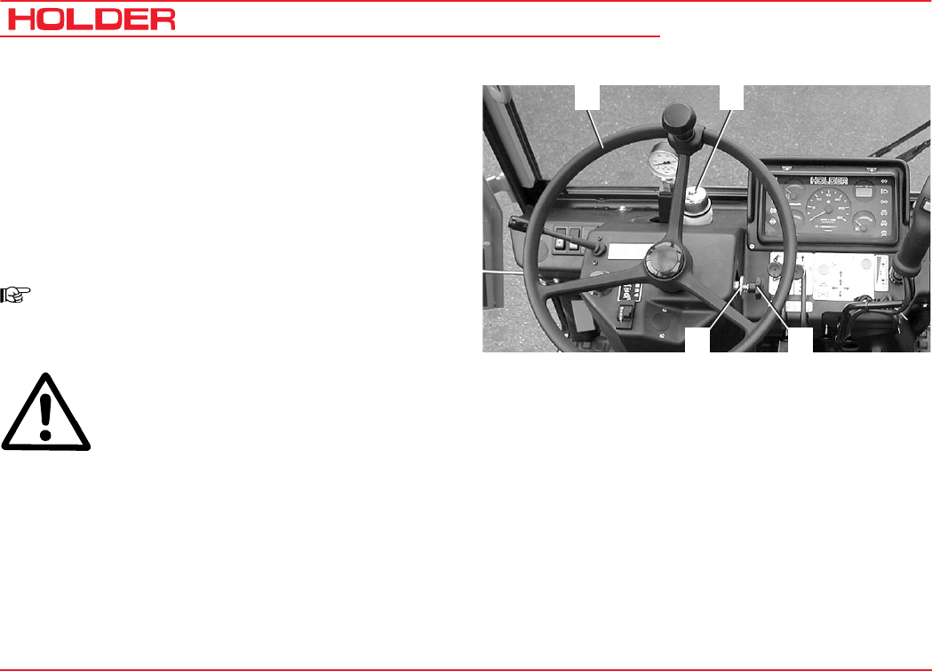
Adjusting the Steering Wheel
NOTE
The tilt of the steering wheel can be set to a
comfortable position.
DANGER
Do not adjust the steering wheel while driving.
- Loosen the star knob (3).
- Pull the slider (4) to the right.
- Adjust the tilt of the steering wheel (1) and release the
slider again.
- Retighten the star knob.
Operating Instructions
145 052 55
C 9700 ... C 9.88 H Taking into Service
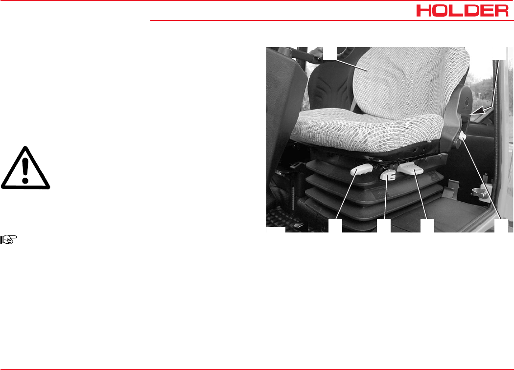
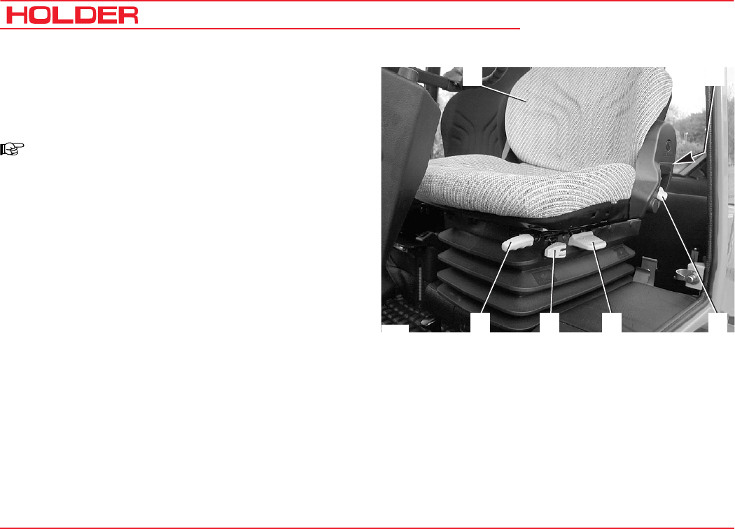
Adjusting the Driver's Seat
1 Backrest
2 Adjustment knob for lumbar padding
3 Backrest adjustment
4 Weight adjustment
5 Horizontal cushioning
6 Horizontal adjustment
DANGER
Do not adjust the seat while driving. Risk of
accidents!
- Adjust the seat so that all controls can be reached
and operated safely.
NOTE
Observe the operating manual for the seat
supplied with your tractor.
Adjusting the Lumbar Padding
- Sit down on the seat and lean against the backrest
(1).
- Turn the adjustment knob for lumbar padding (2) until
the most comfortable position is reached.
12
3
456
Bild_010
Adjusting the Backrest
- Pull the tilt lever (3) up.
- Adjust the inclination of the backrest with your back.
- Release the tilt lever.
C 9700 ... C 9.88 H
Operating Instructions
56 145 052
Taking into Service
12
3
456
Bild_010
Adjusting the Driver's Weight
- Sit down on the driver's seat.
- Pull the weight adjustment handle (4) up.
NOTE
An alert sounds. The seat is automatically
set to the weight of the driver; The alert
ceases.
- Release the lever.
Adjusting the Horizontal Suspension
- Push the horizontal suspension lever (5) back:
the seat suspension is unlocked in horizontal direc-
tion.
- Move the horizontal suspension lever (4) forward: the
seat suspension is locked in the horizontal direction.
Adjusting the Seat Horizontally
- Pull the horizontal adjustment lever (6) up.
- Slide the seat horizontally forward or rear to the
suitable seat position.
- Release the horizontal adjustment lever.
Operating Instructions
145 052 57
C 9700 ... C 9.88 H Taking into Service
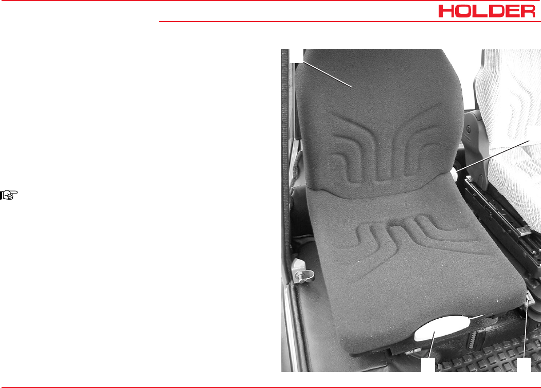
Adjusting the Passenger Seat
1 Backrest
2 Weight adjustment
3 Horizontal adjustment lever
4 Backrest tilt adjustment
Adjusting the Weight
- Sit down on the seat.
- Press the weight adjustment knob (2) from the top
down until the weight is reached on the scale; The
weight can be adjusted in 9 stages of 50 to 130 kg.
- Release the knob when your weight is indicated.
NOTE
Only push the knob from the top down.
- At the bottom press the knob against the stop - the
weigh adjuster automatically resets the seat to 50 kg.
- Release the knob.
Adjusting the Seat Horizontally
- Pull the horizontal adjustment lever (3) up.
- Slide the seat horizontally forward or rear to the
suitable seat position.
- Release the horizontal adjustment lever.
Adjusting the Backrest Horizontally
- Pull the tilt lever (4) up.
- Adjust the inclination of the backrest with your back.
- Release the tilt lever.
1
2
3
4
C 9700 ... C 9.88 H
Operating Instructions
58 145 052
Taking into Service
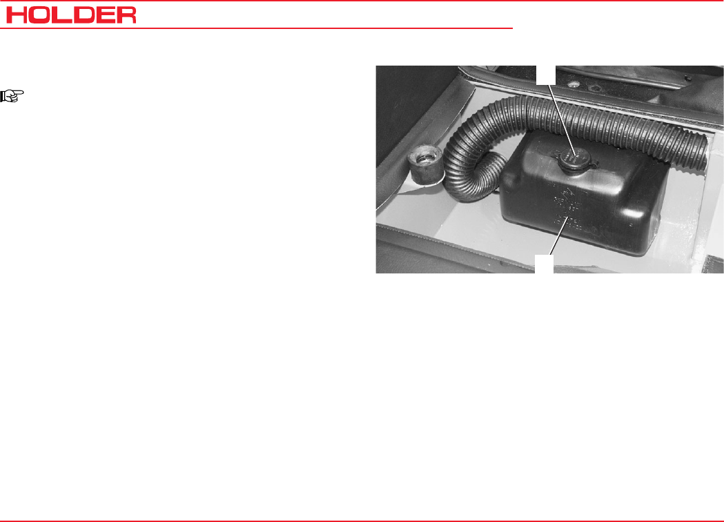
Filling Washing Water
NOTE
The washing water reservoir for the windshield
washer is located beneath the passenger
seat.
- Tilt the seat forward.
- Open the filler cap (1) and add washing water into the
reservoir (2).
Filling capacity ............approx. 2.5 litres (0.66 USGAL.)
Checking the Lights and Rear View Mirror
- Check that the lighting is functioning properly. Carry
out the check according to the instructions in the
section entitled "Lights".
- Adjust the rear view mirror so that the roadway behind
the tractor and the working area are easily seen.
1
2

Operating Instructions
145 052 59
C 9700 ... C 9.88 H Taking into Service
Starting the Engine
Instructions before Starting the Engine
DANGER
Do not start or run the engine in enclosed
spaces. Danger of poisoning through exhaust
gases!
Instructions before Starting
CAUTION
Before starting, check to ensure no one is in
the vicinity of the tractor.
ATTENTION
Do not use a starting aid such as Startpilot
or similar means. Turn off the drive or driven
attaching implements.
CAUTION
Start the engine only from the driver's station.
C 9700 ... C 9.88 H
Operating Instructions
60 145 052
Taking into Service
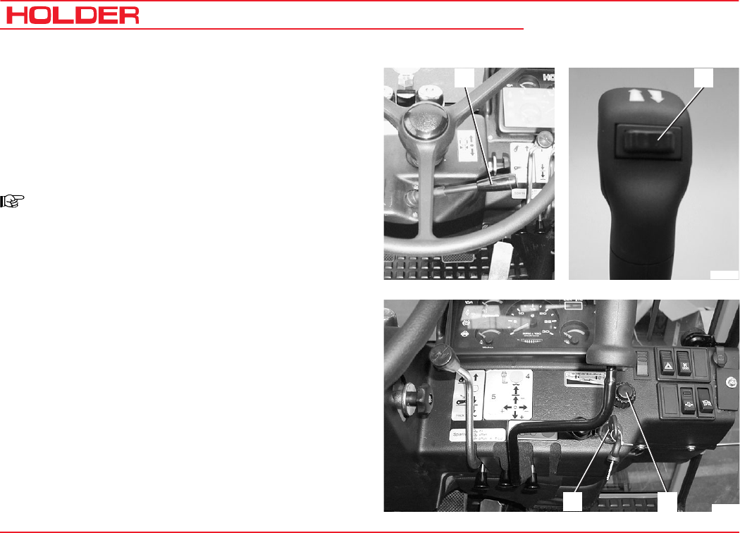
Starting the Engine
- Shift the gearshift lever (gearbox) to neutral.
- Set the forward/reverse selector lever (1) to the
neutral position (centre).
- Depress the clutch pedal (gearbox) or inch pedal
(hydrostatic drive).
NOTE
The engine can only be started if the pedal is
fully depressed (starting safety switch).
- Set the hand throttle (2) to idle (push in fully).
- Insert the ignition key and turn the preheat/starter
switch (3) to position 1.
2Bild_113
3
Bild_180
1
1
Operating Instructions
145 052 61
C 9700 ... C 9.88 H Taking into Service
3
4
8
7
6
Bild_033
5
NOTE
The battery charge indicator (8), engine oil
pressure indicator (7), parking brake indica-
tor(6) (if parking brake is engaged) and the
red indicator for km/h or x10 (3) in the multi-
function display come on.
- Turn the ignition key to position 2 to preheat the
engine. The preheating indicator (4) comes on.
NOTE
When starting at low temperatures, hold the
ignition key longer (approx. 1 minute) in position
2.
- When the preheating indicator goes out, turn the
ignition key to position 3 to start the engine.
ATTENTION
Operate the starter for a maximum of 20 sec-
onds. Wait one minute, then repeat the start-
ing procedure. Repeat the starting procedure
only twice at most. In case the engine does
not start, carry out a troubleshooting accord-
ing to the section entitled "Problems, Causes,
Remedy".
C 9700 ... C 9.88 H
Operating Instructions
62 145 052
Taking into Service
- Release the ignition key as soon as the engine turns
over. The battery charge indicator (8) and the engine oil
pressure indicator (7) will go out.
- Set the engine speed with the hand throttle (1) or
accelerator pedal to the desired RPM (5) .
3
4
8
7
6
Bild_033
5
Checking the Brakes and Steering for Proper Operati-
on
- Make a short trial run and check the steering and
brakes for proper operation.
DANGER
Do not drive a tractor with a defective steering
and/or braking system.
1Bild_032

145 052 63
C 9700 ... C 9.88 H Operating Instructions
Operation
Before Starting to Drive
When driving on public highways, observe the regulations
of the highway code.
• When following a curve with a trailer or other attach-
ments, don't forget to take the added length and drag into
consideration.
DANGER
Parts of implements posing a danger to traffic
must be covered before driving or identified
with warning signs.
• Switch off the differential lock when travelling along a
curve.
• When driving on slopes, drive downhill if possible; if
you have to turn, turn only when driving uphill.
• On steep slopes you can improve traction by acti-
vating the differential lock.
• Drive across slopes only in accordance with the notes
at the end of this chapter.
Driving Safety Rules
• Drive the tractor only from the driver's station with the
cab doors closed.
• Always adjust your speed to the driving conditions
and the load you are carrying.
• Never drive downhill without having the tractor in gear
or with the engine stopped.
• Before driving, check that no-one is standing in the
immediate vicinity of the vehicle.
• The driving behaviour of the tractor is strongly affec-
ted by the weight and swing range of the implements,
trailers and, if fitted, ballasting. Therefore drive slowly
with heavy equipment and take the longer braking
distance into consideration.
C 9700 ... C 9.88 H
Operating Instructions
64 145 052
Operation
Driving
Driving with Hydrostatic Drive and Digital Electronics
- Start the engine.
- Select the direction of travel with the forward/reverse
selector lever (3) (forward left or reverse right).
- The direction arrow for forward (1) or reverse (2) travel
comes on.
NOTE
After starting the engine, the forward/reverse
selector lever must be operated once if it was
in the forward or reverse position when starting.
This prevents any accidental movement of the
tractor when starting the engine.
NOTE
You can also select the new direction while
travelling at reduced speed.
CAUTION
The tractor will brake strongly and accelerate
in the opposite direction.
4
Bild_108
3
1 2
3
Bild_181
- Set the drive range pre-selection lever (4) (between
the seats) to the desired driving range:
ATTENTION
This must only be done when the tractor is
stationary.
Operating Instructions
145 052 65
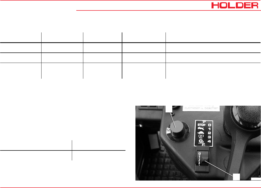
C 9700 ... C 9.88 H Operation
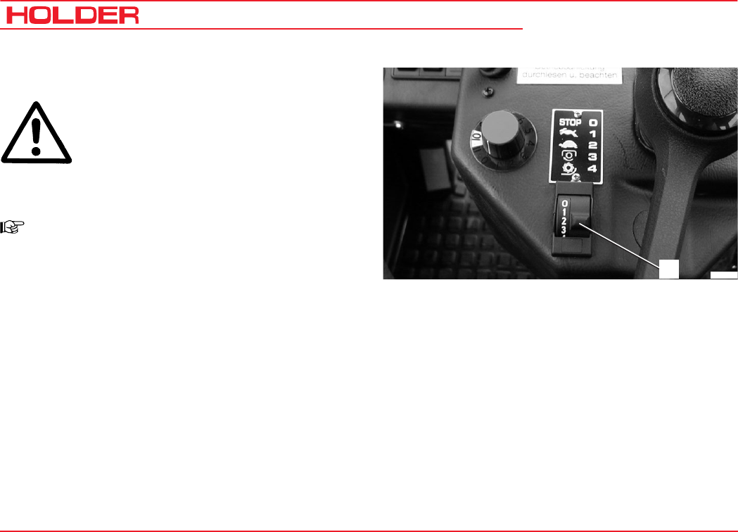
Table of Driving Ranges
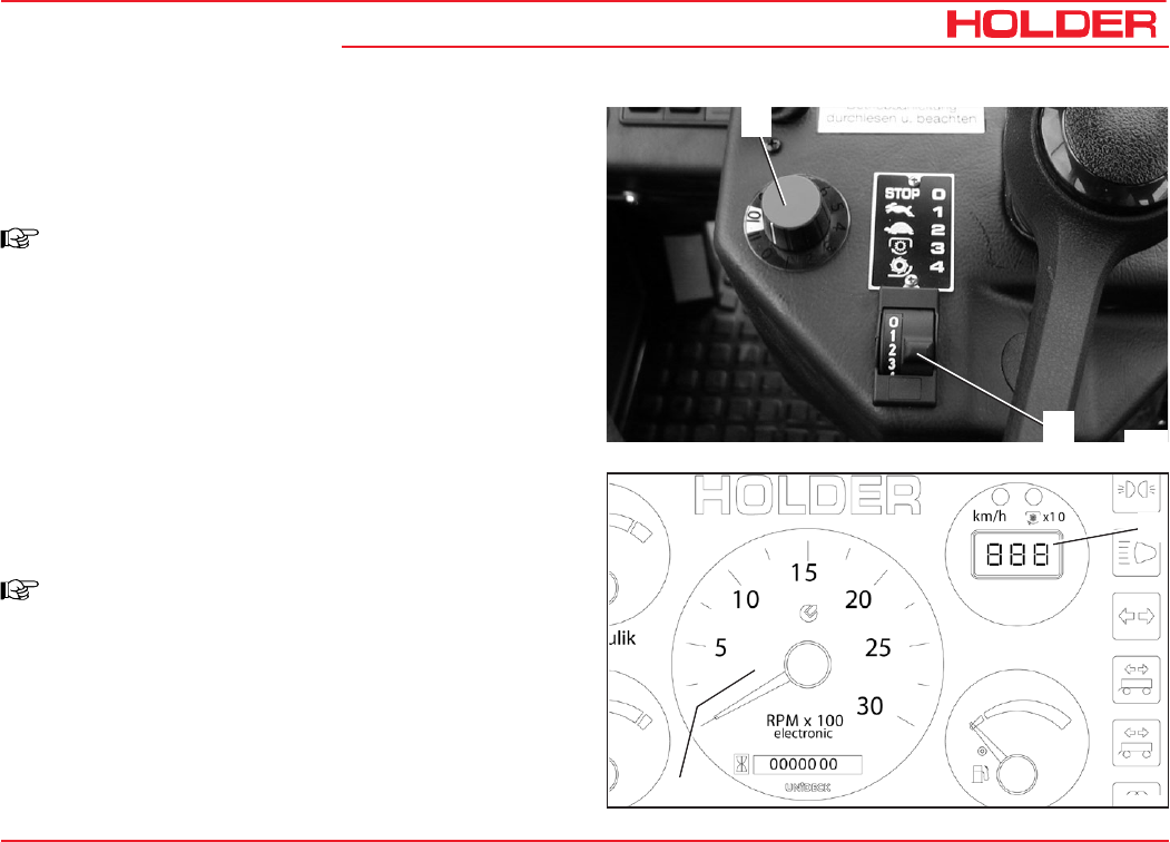
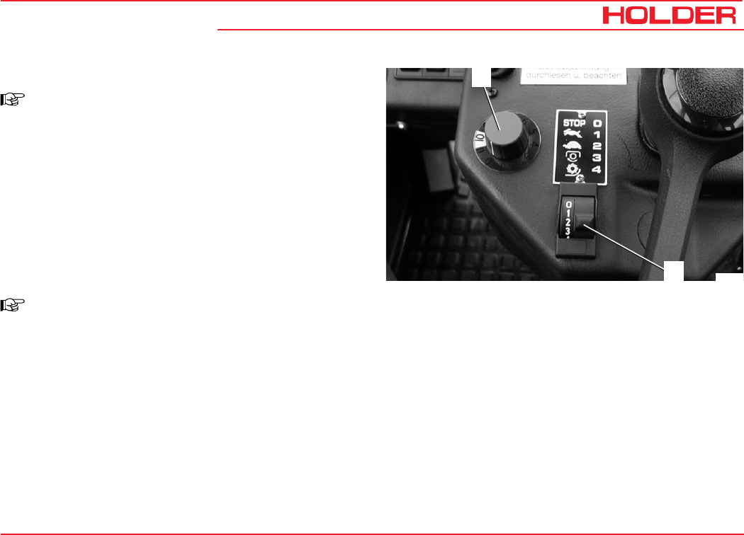
- Select the desired driving program at the driving
program switch (6). The selected position is illumina-
ted:
You can select 4 programs:
Bild_075
6
5
* Depending upon the model
Position Symbol Function Travel Speed* Use
Top position S Fast speed 0 - 30 / 36 km/h Low tractive force, eg for highway driving
Centre position 0 Drive off Towing
Bottom position L Slow speed 0 - 11.5 km/h High tractive force, eg for working
operation or pulling trailers on gradients
Stage 1 and 2 programs eg road travel
Stage 3 and 4 programs eg working operation

C 9700 ... C 9.88 H
Operating Instructions
66 145 052
Operation
Table of Driving Programs*
Position Symbol Function Use
Range 0 STOP Drive off
Range 1 Rabbit symbol Maximum speed eg for highway driving
Range 2 Turtle symbol Maximum speed eg for highway driving
Range 3 PTO symbol
Travel speed adjustable with fine adjustment
knob, is controlled automatically in case of high
power demand of implement
eg for mowing
Range 4 Snow blower
symbol
Travel speed adjustable with fine adjustment
knob, is controlled automatically in case of high
power demand of implement
eg special setting for
snow blower
* The driving programs can be optimised for special operations by your Service,
eg controlled constant driving speed
Operating Instructions
145 052 67
C 9700 ... C 9.88 H Operation
Selecting Road Speed (Transport Speed)
The tractor is stationary.
- Set the program switch (6) to range 1 or 2.
NOTE
The driving range can also be switched while
driving at reduced ground speed.
- Disengage the parking brake.
- Depress the accelerator pedal for the desired ground
speed.
The tractor starts driving and can be driven up to
maximum ground speed of the selected range.
- You can read the engine speed (8) and ground speed
(7) on the multi-function display.
Setting the Working Speed of Programs 3 and 4
NOTE
With programs 3 and 4 you can select the
ground speed independent of the PTO rpm.
Bild_075
6
5
Bild_076
7
8
C 9700 ... C 9.88 H
Operating Instructions
68 145 052
Operation
The tractor is stationary.
- Set the inch knob (5) to 0.
- Set the program switch (6) to range 3 or 4.
- Adjust the PTO rpm with the hand throttle.
NOTE
The engine speed must reach at least 1500 rpm
as the control is only effective beginning at this
speed. You can read the speed on the multi-
function display.
NOTE
You can also switch ranges while driving.
The ranges 3 and 4 provide a speed as required by the load
on the PTO.
This means that if, for example, the snow blower requires
more power when meeting high resistance, the tractor drives
more slowly. As the resistance decreases, the tractor ac-
celerates again to the previously selected ground speed.
Driving range 4 is especially adapted for particular applica-
tions.
- Set the PTO clutch lever (7) fast to the vertical
position to engage the PTO.
- Disengage the parking brake.
Bild_075
6
5
7
Bild_077
Operating Instructions
145 052 69
C 9700 ... C 9.88 H Operation
Adjusting the Inch Knob
NOTE
While driving you can adjust the inch knob
(5) at any time for fine and infinitely variable
control of the ground speed.
- In position 0 the tractor is stationary. When turned
further clockwise, the tractor starts driving and at the
maximum scale position 11, the maximum ground
speed of the driving range is achieved.
- You can read the engine speed and ground speed at
the multi-function display.
NOTE
In this operating mode, the tractor drives
automatically and needs only to be steered.
This mode is best for operating an implement as you can
concentrate fully on controlling the implements.
Bild_075
6
5
C 9700 ... C 9.88 H
Operating Instructions
70 145 052
Operation
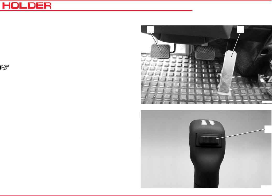
Operating the Inch Pedal
7 Inch pedal
8 Accelerator pedal
This function is active for all driving programs.
NOTE
The inch pedal allows driving speed to be
reduced temporarily.
- Depress the inch pedal (7) to reduce driving speed
and to stop completely.
- Release the inch pedal again behind the obstacle.
The tractor will resume the previously selected driving
speed.
Changing the Direction of Travel
- Preselect the new direction with the forward/reverse
selector lever (9).
- The tractor will come to a standstill and accelerate
again in the opposite direction.
78
Bild_078
9
Bild_081
Operating Instructions
145 052 71
C 9700 ... C 9.88 H Operation
Driving with Hydrostatic Drive, Digital Electronics
and Dual Drive
- Set the drive range pre-selection lever (1) to "S".
The DUAL Drive will work only in this driving range.
1
Bild_069
Table of Driving Ranges with Dual Drive
* Depending on the version
Position Symbol Function Hydrostatic Speed* DUAL Drive Speed* Use
Top position S Fast range 0 - 30 / 36 km/h 0 - 30 / 42 km/h Low tractive force,
eg for road travel
Centre position 0 Drive off For towing
Bottom position L Slow range 0 - 11.5 km/h/ 14.5
km/h -
High tractive force, eg
for working or pulling
trailers on gradients
C 9700 ... C 9.88 H
Operating Instructions
72 145 052
Operation
- Set the program switch (2) to driving range 2.
ATTENTION
Drive the tractor warm for approx. 10-12 min.
at driving range 2.
- Set the program switch to driving range 1.
NOTE
The functions of the drive are same except
for the overdrive:
When the driving speed* exceeds 25 km/h,
the transmission automatically shifts from the
hydrostatic drive to the mechanical gear.
If the driving speed drops again, the
transmission shifts back to the hydrostatic
drive.
* Depending on the version
Bild_192
2
Operating Instructions
145 052 73
C 9700 ... C 9.88 H Operation
1
Bild_079
23
Bild_082
45
Driving with the Mechanical Gearbox
- Set the gearshift lever to the neutral position.
- Start the engine.
- Select the direction of travel with the forward/reverse
selector lever (1) (forward or reverse). The indicator
will flash green (forward or reverse).
- Fully depress the clutch pedal (2) (buzzer sounds
until shifting is completed). The indicator is now
illuminated green.
- Shift the gearshift lever (4) left (looking forward) into
the desired gear.
4 gears 1-2-3-4 are available.
- Shift the range selector lever (5) right (looking forward)
in the desired speed range.
4 speed ranges are available:
S - Fast
M - Medium
L - Slow
LL - Very slow
C 9700 ... C 9.88 H
Operating Instructions
74 145 052
Operation
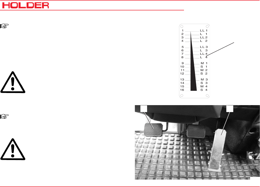
NOTE
The label (4) shows the possible shift
combinations. You have a total of 16 gears
available, both for forward and for reverse
travel.
- Release the clutch pedal (5) to start driving.
ATTENTION
Do not keep the foot on the clutch pedal when
driving.
- Control the driving speed with the accelerator pedal
(6) or the hand throttle.
NOTE
The attainable driving speeds can be read in
the table in the technical data section.
ATTENTION
When downshifting, the driving speed must
be reduced and lie in the area of the low speed
range. As the transmission is synchronized,
you do not have to give gas when
downshifting.
56
Bild_109
Bild_083
4
Operating Instructions
145 052 75
C 9700 ... C 9.88 H Operation
Changing the Direction of Travel
ATTENTION
The direction of travel can be changed when
driving slowly.
- To change the driving direction from forward to
reverse, the forward/reverse selector lever (1) must
be pulled back.
- The indicator (3) flashes green and shows the selec-
ted direction of travel.
- As soon as the clutch pedal is fully depressed, a
buzzer sounds until shifting is completed. Then the
indicator (3) is steadily illuminated green.
- Release the clutch pedal to drive in reverse.
NOTE
When working, we recommend preselection
of the direction of travel while driving.
ATTENTION
If the clutch pedal is released before the
shifting is completed, the mechanical gear
shifts into neutral (0). Both arrows are flashing
(2 and 3).
- Depress the clutch pedal again.
The green indicator is on steadily, shifting is comple-
ted.
Bild_182
1
3
2
C 9700 ... C 9.88 H
Operating Instructions
76 145 052
Operation
Engaging the Differential Lock
NOTE
With the differential lock you can improve
traction on soft , slippery ground. The lock is
engaged when the engine speed is over 1000
rpm. You can keep the differential lock
engaged steadily and also only briefly by
toggling the switch momentarily.
ATTENTION
The differential lock may only be used when
driving straight.
- Toggle the differential lock switch (1) down and hold
it.
The indicator (2) in the multi-function display comes
on red. An intermittent alert sounds at the same time.
The differentials of both axles are locked and power is
transferred to all 4 wheels equally.
- Toggle the differential lock switch (1) up. The switch
remains on until you return it to the middle position
again.
Disengaging the Differential Lock
- Return the differential lock switch (1) to the middle
position. The differentials are in operation again.
The indicator (2) goes out and the alert in the multi-
function display ceases.
Bild_085
1
Bild_084
2
Operating Instructions
145 052 77
C 9700 ... C 9.88 H Operation
Steering
The articulated steering is operated hydraulically. The wheels
also stay in track in curves, so that implements are guided
without any lateral offset.
Steering
- Turn the steering wheel (1) in the desired direction.
The possible turning radii depend on the tires and track widths
of your tractor. For exact information refer to the track width
table in the section "Technical Data".
Braking
The service brake is a wet disc brake mounted in the front
axle. It is operated hydraulically and acts on all four wheels.
The parking brake is mechanical and operated with the
parking brake lever.
Operating the Service Brake
ATTENTION
The engine can stall if you brake too hard in
the mechanical gear.
- Depress the brake pedal (2).
NOTE
If the mechanical gearbox is fitted, the clutch
pedal must also be operated.
1
2
Bild_035
C 9700 ... C 9.88 H
Operating Instructions
78 145 052
Operation
Engaging the Parking Brake
ATTENTION
The parking brake is not intended to be used
for braking while driving.
- Pull the parking brake lever (2) up.
The parking brake is engaged, the parking brake
indicator (3) in the multi-function display comes on
red.
Disengaging the Parking Brake
- Pull on the parking brake lever (2) slightly. While
depressing the release button (1) in the lever, push
the lever downwards.
The parking brake is disengaged, the parking brake
indicator goes out.
ATTENTION
An alert is sounded when driving with the
parking brake applied.
1 2
Bild_086
3
Operating Instructions
145 052 79
C 9700 ... C 9.88 H Operation
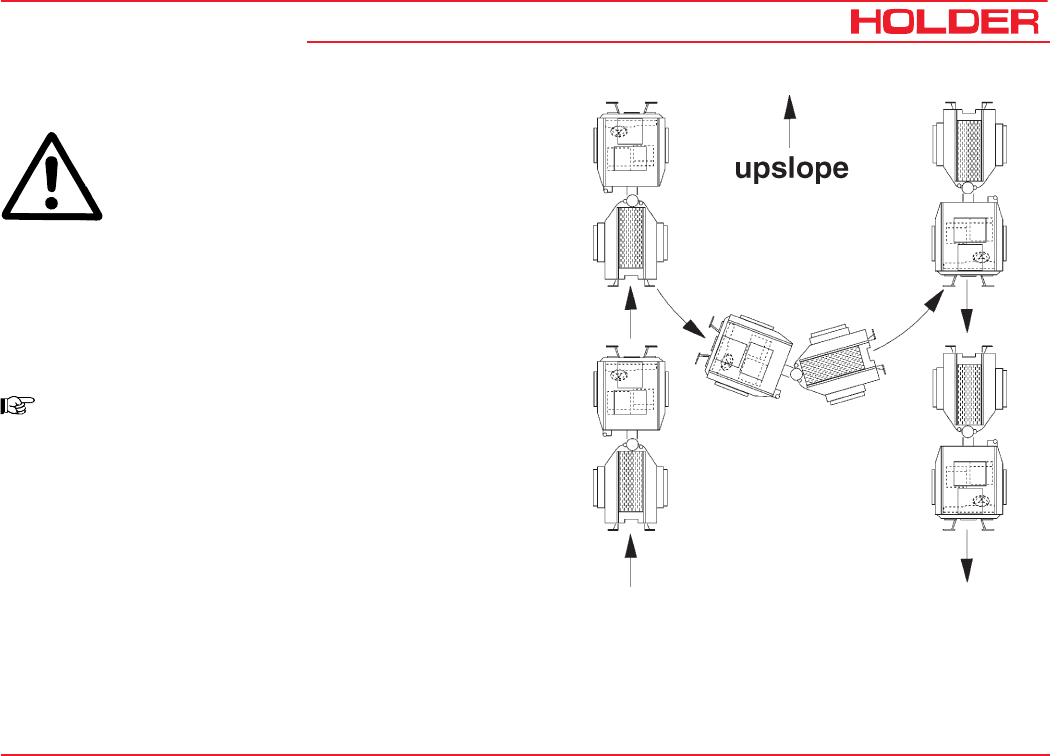
Driving on Slopes
DANGER
Driving on slopes is dangerous as the tractor
can tip over if the centre of gravity exceeds
the tip-over limit on an extreme slope.
The following factors reduce the hazard:
- small or no load
- low ground speed
- low gradient
- low tire inflation pressure
NOTE
The driving comfort and the traction of the
tractor can be improved by reducing the
inflation pressure.
- large track width
- level, non-bumpy terrain
When turning on slopes we recommend the proceeding as
shown in the drawing on the right.
145 052 81
C 9700 ... C 9.88 H Operating Instructions
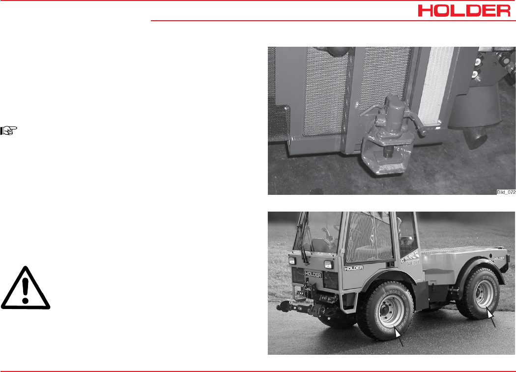
Special Operating Instructions
Stationary Operation
The tractor can be used for stationary operation, for example,
to drive a water pump via the PTO shaft.
ATTENTION
Place the tractor on level ground in both
directions.
- Attach the stationary equipment to the PTO shaft (1).
- Set the gearshift lever (with a mechanical gearbox the
gearshift and range selector lever) to the zero positi-
on.
- With a hydrostatic drive, set the program switch to 0.
- Apply the parking brake.
DANGER
Before switching on the PTO, make sure no-
one is standing in the vicinity of the tractor
and the rotating PTO shaft.
Hydraulic Oil Flow for Stationary Operation
When the tractor is stationary, hydraulic oil is available, for
example, for the operation of a hydraulic pump.
Max. oil quantity available .......... 22 litres (5.8 USGAL.)
ATTENTION
Before starting to drive after stationary
operation, first check the hydrostatic steering.
Turn the steering wheel fully to the right and
left several times to release air from the
steering system.
1

C 9700 ... C 9.88 H
Operating Instructions
82 145 052
Special Operating Instructions
Adjusting the Track Width
You can widen the track width of the tractor by adding spacers.
You have a choice of 3 different spacers.
DANGER
Observe the safety notes on safe parking and
jacking up for the wheel change in the
maintenance manual.
- Remove the wheels. Turn the wheels inside out or
install the selected spacers.
ATTENTION
The same spacers must be installed on all
four wheels.
NOTE
The arrows on the tires must show in the
forward direction of rotation.
- Tighten the wheel nuts to the specified torque.
Torque to ............................................................ 340 Nm
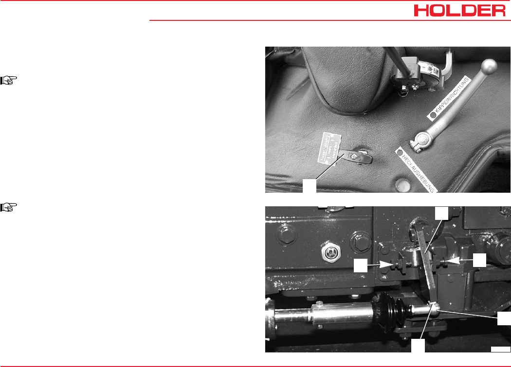
Operating Instructions
145 052 83
C 9700 ... C 9.88 H Special Operating Instructions
1
1
Bild_089
V
2
3
R
Operating the Emergency Start (Hydrostatic Drive
with Dual-Drive Only)
NOTE
In case the engine was stalled and can not be
started again, the emergency start must be
operated before a renewed starting attempt.
- Fully depress the inch pedal.
- Briefly operate the starter.
- Pull the handle for the emergency start (1) up.
- Start the engine again.
Operating the Emergency Shift (Mechanical Gearbox
Only)
NOTE
In the event of a failure of the electrical
installation, it is possible to drive to an authorized
workshop with the emergency shift.
- Turn off the engine.
- Apply the parking brake
- Put the range selector lever and the gearshift lever in
neutral
- Remove the wire safety (3).
- Carefully press the ball socket of the servo motor (2)
down until it is disconnected.
- Move the operating lever (1) to the desired position. V
= forwards or R = reverse.
- Start the engine and drive to the workshop.

C 9700 ... C 9.88 H
Operating Instructions
84 145 052
Special Operating Instructions
Operation in Winter
Preheating of Oil*
Before starting the engine at temperatures below - 20 °C,
turn on the heating element* for preheating the oil.
- Connect the preheating system plug to a 230 VAC
(U.S.: 120 V) source.
Follow the Operating Instructions of the manufacturer.
Winter Diesel Fuel
Whenever temperatures fall below 0 °C, use winter diesel or
super diesel fuel or additives recommended in the
maintenance manual.
Engine Oil for Winter Operation
Fill engine oil with a suitable SAE class as recommended
the maintenance manual.
The cold start capability of the engine can be reduced if the
temperature limits are underrun occasionally, but this does
will not damage the engine.
Hydraulic System
The hydraulic functions are sluggish and slower during cold
temperatures. Bring the hydraulic system to operating
temperature by operating it without a load.
Putting on Snow Chains
Snow chains can be mounted on the tires to improve grip.
In the following table you will find the order numbers for
RUD chains which fit on the listed tires. You can also fit
snow chains from other manufacturers if these have the
proper dimensions.
Ballast Weights
The weight of the machine can be increased with ballast
weights. The ballast weights must be applied parallel with
the same weight on each axle and side.
* Option
Tires Snow chain type
(RUD Order No.)
10.5-18 MPT 24 553 and 22 553
400/60-15.5 22 177
33x12.50 R 15/33x12.5-15 22 167
33x15.50-15 22 174
31x15.50-15 Terra 22 548
36x13.5-15 24 178

145 052 85
C 9700 ... C 9.88 H Operating Instructions
Operating the Implements
We have tested and approved a large number of possible
implements for use with this tractor. We recommend
contacting our customer service before installing special
equipment.
Possible Implements
Rotary mower with different widths
Reel mower
Flail-type mower
Hedge cutters
Leaf blower and grass collector
Weed brushes and -burners
Weed killers
Casting fixtures
Distributors for service in winter
Conveyor feed distributors for different distribution widths
Snow blowers
Snow plow
Sweepers
Spray and high-pressure cleaners
Oil removal device
Safety Instructions for Handling Implements
Before the installation of implements, the tractor must be
parked safely.
It must be secured against rolling, for example, with the
parking brake or, if required, with chocks.
DANGER
Be careful to avoid injury from being crushed
or cut when implements are being attached.
DANGER
No-one must come between the tractor and
implement unless the tractor is secured against
rolling.
For highway driving purposes, the implements
must be lifted and secured against lowering.
Observe the applicable safety regulations for
your implement. Observe the Operating
Instructions and the safety rules for your
implement.
DANGER
During work breaks, the implement must always
be lowered to the ground in order to relieve the
hydraulic cylinders. Accidents can occur if the
lowering is uncontrolled, for example, due to
damage or accidental movement of the control
levers.
DANGER
Any parts of the implements posing a traffic
hazard must be covered before driving or
identified with warning signs.
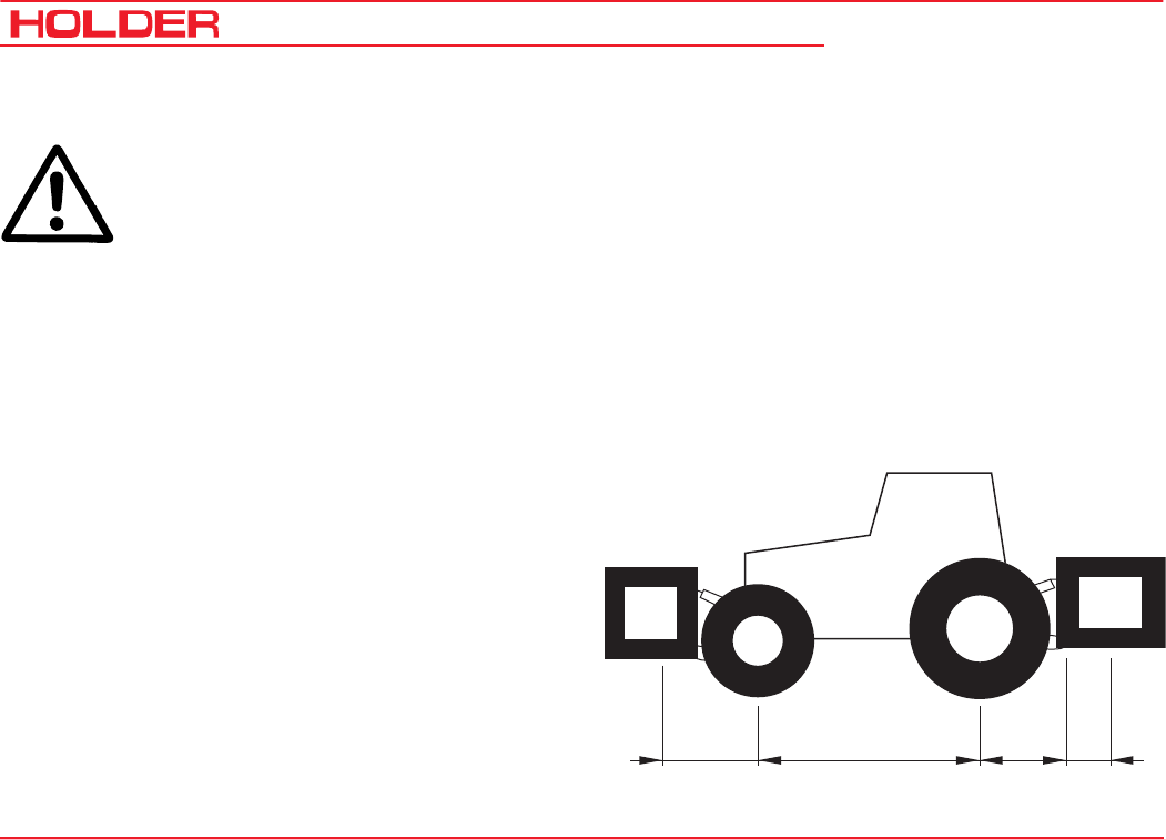
C 9700 ... C 9.88 H
Operating Instructions
86 145 052
Operating the Implements
Additional Information for Implements
When installing attachments on the front and
rear 3-point lift, do not exceed the permissible
total weight , the permissible axle loads and tire
carrying capacities of the tractor. The front axle
of the tractor must always be loaded with at least
20 % of the tractor's empty weight.
Before the purchase of equipment, make sure
these conditions are met by performing the
following calculations or by weighing the tractor-
equipment combinations.
Determining the Total Weight, Axle Loads and Tire
Carrying Capacity including the Minimum Ballasting
For the calculation you need the following data:
TL(kg) Empty weight of the tractor 1)
TV(kg) Front axle load of the empty tractor 1)
TH(kg) Rear axle load of the empty tractor 1)
GH(kg) Total weight
rear implement/rear ballast 2)
GV(kg) Total weight
Front implement/front ballast 2)
G
v
G
H
T
v
T
H
abcd
a (m) Distance between centre of gravity
of front implement/front ballast and
centre of front axle 2) 3)
b (m) Tractor wheelbase1) 3)
c (m) Distance between centre of rear axle
and centre of lower link ball1) 3)
d (m) Distance between centre
lower link ball and centre of gravity of
rear implement/rear ballast 2)
1) See operating manual, Technical Data
2) See price list and/or operating manual of the implement
3) Measure

Operating Instructions
145 052 87
C 9700 ... C 9.88 H Operating the Implements
Rear Implement or Front/Rear Combinations
1) Calculation of the minimum front ballasting GV min
G
V
min=
G
H
·
(c+d)-T
V
·b
+0.2·
T
L
·b
a
+
b
Enter the calculated minimum ballasting required for the
front of the tractor in the table.
Front Implement
2) Calculation of the minimum rear ballasting GH min
G
H
min=
G
V
·a-T
H
·
b
+
X·T
L
·
b
b+c+d
the calculated minimum ballasting required for the rear of
the tractor in the table.
(Value X is 0.25 for Holder tractor 4-wheel)
3) Calculation of the actual front axle load TV tat
(If the minimum front ballasting (GV min) is not obtained with
the front implement, the weight of the front implement must
be increased to the weight of the minimum front ballasting.)
T
V
tat=
G
V
·(a
+
b)
+
T
V
·b-G
H
·(c
+
d)
b
Enter the calculated actual and the permissible front axle
load specified in the operating manual of the tractor in the
table.
4) Calculation of the actual total weight Gtat
(If the required minimum rear ballasting (GH min) is not obtained
with the rear implement (GH), the weight of the rear implement
must be increased to the weight of the minimum rear
ballasting.)
G
tat=
G
V
+
T
L
+G
H
Enter the calculated actual and the permissible total weight
specified in the operating manual of the tractor in the table.
5) Calculation of the actual rear axle load TH tat
T
H tat
=
G
tat
-
T
V tat
Enter the calculated actual and the permissible rear axle
load specified in the tractor operating manual in the table.

C 9700 ... C 9.88 H
Operating Instructions
88 145 052
Operating the Implements
6) Tire carrying capacity
Enter the double value (two tires) of the permissible tire
carrying capacity (eg see tire manufacturer documentation)
in the table.
Actual Calculated Weight
Specified Permissible
Weight acc. to operating
instructions
Double Permissible Tire
Load Capacity
(Two Tires)
Minimum ballast at
front/rear / kg - -
Total weight kg ≤kg -
Front axle kg ≤kg ≤kg
Rear axle kg ≤kg ≤kg
The minimum ballasting must be mounted on the tractor either as attachment or ballast weight!
The calculated weights must be lower/higher (≤) than the permissible weights!
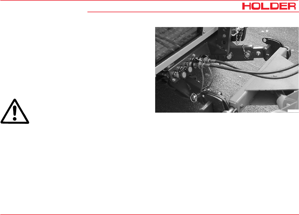
Operating Instructions
145 052 89
C 9700 ... C 9.88 H Operating the Implements
Attaching Implements
The various implements are attached to the front lift or rear
lift*.
There are 2 different fastening categories:
Category I Pin diameter 22 mm
Category II Pin diameter 28 mm
The tractor can be adjusted to both categories by adjusting
the catch hook bars and providing the catch hooks with or
without reducer sleeves.
DANGER
Use only the following specified devices for
attaching your implement.
Secure the implement against shifting or
rolling off.
* Option
Bild_070
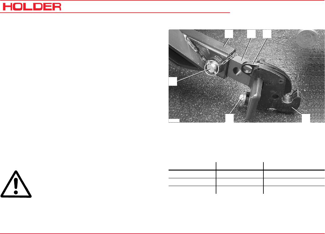
C 9700 ... C 9.88 H
Operating Instructions
90 145 052
Operating the Implements
Adjusting Catch Hook and Catch Hook Bar
You can adjust the catch hook laterally and longitudinally.
- Measure the stand-off of the pins on your implement.
- Disengage the clamping screws (6) on both sides.
- Slide the catch hook laterally until the required distance
is reached.
- Retighten the clamping screws.
- Equipment of category II can be attached with the catch
hook (5) directly;
- For equipment of category I install the reducing
sleeves on the left and right.
Adjusting the Length of the Catch Hook Bar
- Disengage 2 locknuts and clamping screws (inside and
at bottom) on the lower link (2).
- Pull the linch pin out of the pin (1) and remove the pin.
- You can put the catch hook bar (3) in one of 3 positions.
- Insert the pin (1) in the hole and secure with the linch
pin.
- Retighten the locknuts and clamping screws.
DANGER
Make sure no-one is standing between the
tractor and implement.
- Drive the tractor to the implement to be picked up.
1 Pin with linch pin 4 Quick attach
2 Lower link support 5 Catch hook
3 Catch hook bar 6 Clamping screw
(adjustable) with 3 positions
- Steer the catch hooks (5) below the attaching pin of the
implement.
- Raise the front lift until the quick attach (4) closes and
engages.
234
6
1
5
Bild_53
Hole Position Used for
1st hole Front Category I and II
2nd hole Centre Category I
3rd hole Rear Optional attachments
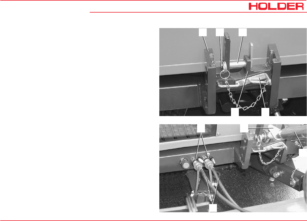
Operating Instructions
145 052 91
C 9700 ... C 9.88 H Operating the Implements
Adjusting the Upper Link Mount
The height of the upper link mount can be adjusted. The
required height depends on your implement.
1 Upper link support
2 Retaining spring
3 Top link pin
4 Height adjustment lever
5 Upper link mount
- Raise the height adjustment lever (4).
- Slide the upper link mount (5) to one of the 4 possible
positions.
- Release the height adjustment lever; the upper link
support engages.
- Pull the retaining spring (2) off the pin (3) and pull the
pin to the side.
- Adjust the upper link (8) to the proper length (screw in
or out by rotating the sleeve); secure the upper link
with the locking lever (7).
- Insert the pin though eyelet on the upper link and
secure the pin again with the retaining spring.
123
4
5
6
9
7
8
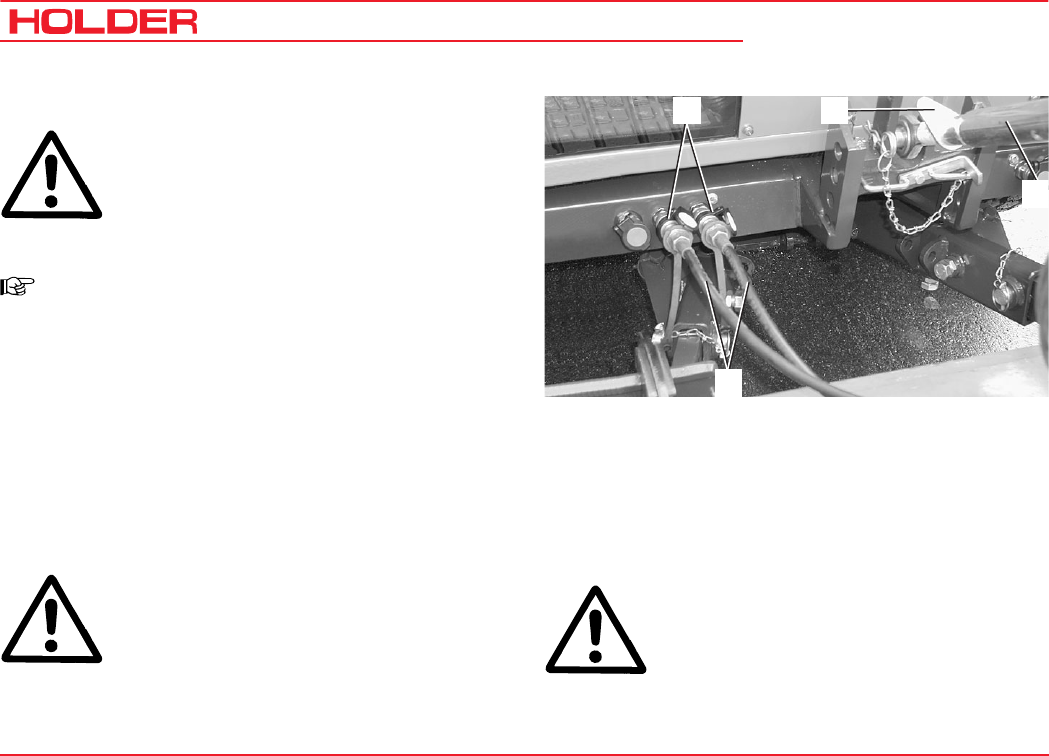
C 9700 ... C 9.88 H
Operating Instructions
92 145 052
Operating the Implements
Coupling Hydraulic Lines
ATTENTION
The hydraulic couplings on the tractor must
be without hydraulic pressure before the
connection. The couplings on the tractor and
the hydraulic hoses must be clean.
NOTE
Each implement has different functions and
hydraulic lines for its control. Observe the op-
erating manual supplied with your implement
and make yourself familiar with the functions
and colour codes.
- Open the protective caps of the hydraulic couplings
(6).
- Attach the colour coded hydraulic hoses (9) of the
implement to the hydraulic couplings of the same
colour on the tractor.
ATTENTION
The hydraulic male couplings fit on each
coupling and can therefore be connected
incorrectly.
6
9
7
8
With the connection you therefore decide
which function/movement of the implement
is actually to be performed with the control
lever assigned to the coupling.
DANGER
If you are not sure about the functions,
determine them with trials at a safe place.
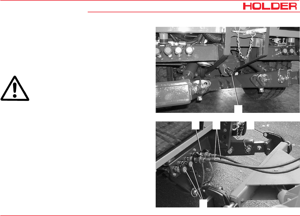
Operating Instructions
145 052 93
C 9700 ... C 9.88 H Operating the Implements
Installing the Cardan Shafts
Only use the shafts suited and intended for the implement.
The shafts are supplied with the implement. The length of
the articulated shaft must adjusted before the first
installation. In case of doubt, please contact our customer
service. Observe installation instructions for the articulated
shaft when installing it.
DANGER
Turn off the engine before the installation. After
the installation, fit the protective devices as
specified. After the removal, cover the PTO
shaft (1) with the protective cap again.
Removing Implements
- Drive the implement to its storage place and lower it
with the front lift.
- Stop the engine, but do not turn off the ignition.
- Operate all control levers for the front lift several times
in all directions. This relieves the pressure in the hydrau-
lic system.
- Slide the outer ring of the hydraulic couplings (1) back
and disconnect the hydraulic hoses (2).
- Close the protective caps of the hydraulic couplings (as
for item 4).
- Remove the upper link from the pin of the upper link
support.
- Pull the quick attaches (3) up to release the implement
pins.
- Lower the front lift and back off.
123
4
1
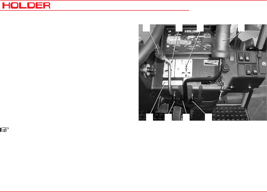
C 9700 ... C 9.88 H
Operating Instructions
94 145 052
Operating the Implements
Operating Implements
Operating the Hydraulic Control Levers
1 Control lever for dump or rear lift*
2 Control lever functions plate
3 Multi-function lever functions plate
4 Multi-function lever*
(front lift and driving direction)
5 Lock knob for longitudinal motion
of the multi-function lever
6 Lock knob for laterally movement
of the multi-function lever
7 Lock knob for longitudinal motion
of the control lever
8 Lock knob functions plate
NOTE
The control levers control those functions of
the implements which are connected to the
front or rear hydraulic couplings. The couplings
and notice plated for the control levers are
colour coded, ie the colours match to the
function.
1234
5
76
8
* Option

Operating Instructions
145 052 95
C 9700 ... C 9.88 H Operating the Implements
DANGER
Due to the variety of implements and
connections, however, we recommend a trial
run of the movement at a safe place without
danger to persons or risk of material damage
before starting operation.
Two types of control levers can be installed: control levers
(1) and multi-function levers (4).
Control Lever Functions
You can recognize the functions on the notice plate (2).
NOTE:At the base of the control lever (1) is a
lock knob (7) with which the motions of the
lever can be locked or released.
The following movements are possible:
- Set the lock knob (7) to the middle position (lever free
to move).
- Push the control lever (1) forward:
• The implement is lifted.
You can stop the movement by releasing the lever.
- To lower the implement, pull the control lever (1)
back:
• The implement is lowered.
- Pull the control lever (1) fully back:
• The float position of the implement is turned on, ie
the implement can be moved with external use of
force. The function is on until the control lever is
disengaged again. It always returns to the neutral
position.
Functions of Lock-out Knob
With the lock knob (7) lever movements can be controlled
as follows:
The functions are shown on the plate (8).
- Knob depressed - lever movement locked
- Knob in middle - lever movement released
- Knob pulled out - float position released
NOTE:
If the lever movement is locked, you can
prevent any unintended movement of the
implement.
Transport lock for road travel.
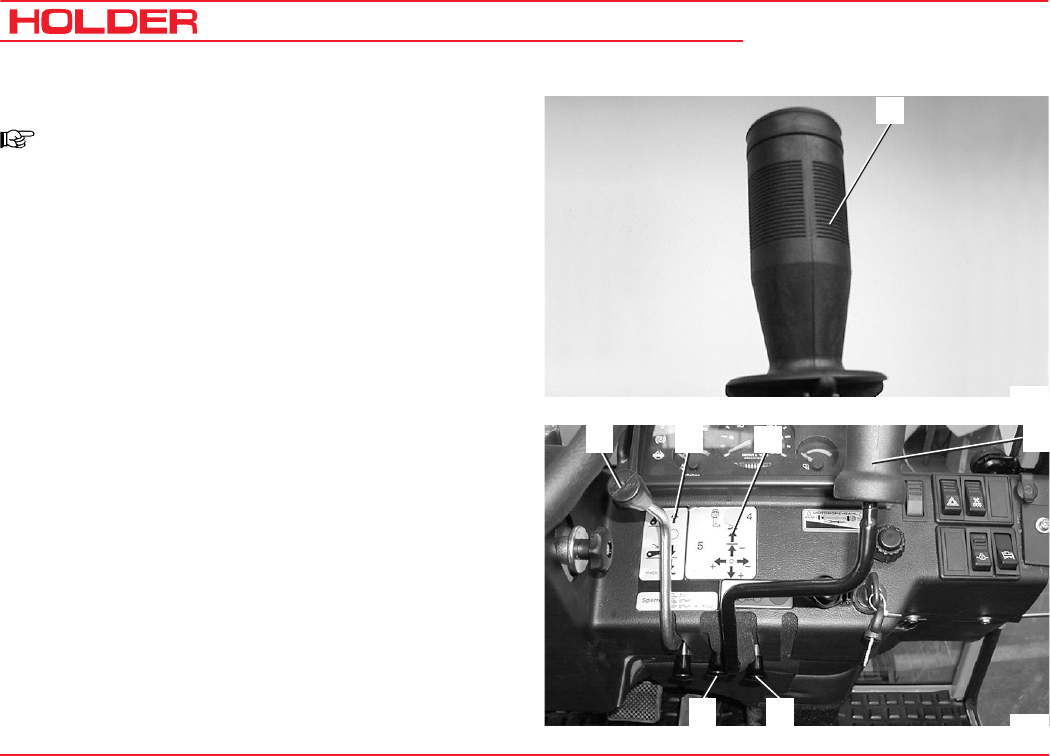
C 9700 ... C 9.88 H
Operating Instructions
96 145 052
Operating the Implements
Multi-function Lever Functions
NOTE
Different versions of the multi-function lever
can be installed.
Multi-function Lever (Variant 1)
Multi-function lever (4) (without forward/reverse selector
switch)
The multi-function lever can be operated forward and back
as well as to the right and left: The functions are shown on
the plate (3).
The following movements are possible:
- Fully pull out the lock knobs (5 and 6) (lever move-
ment).
- Push the multi-function lever (4) forward:
• The implement is lowered.
You can stop the motion by releasing the lever.
- For lifting, pull the multi-function lever (4) back:
• The implement is lifted.
4
Bild_018
1234
5
6
Bild_088

Operating Instructions
145 052 97
C 9700 ... C 9.88 H Operating the Implements
- Push the multi-function lever (4) fully forward:
• The float position of the implement is turned on, ie
the implement can be moved with external use of
force. The function is on until the multi-function
lever is pressed out of the detent again. It always
returns to the neutral position.
- Push the multi-function lever (4) to the right:
• The implement is swung to the right*.
- Push the multi-function lever (4) to the left:
• The implement is swung to the left*.
* For example, when a snow plough is attached.
NOTE
Lock knob (5) controls the longitudinal motion,
lock knob (6) the lateral movement of the
multi-function lever.
There is no float position for the lateral
movement of the multi-function lever.
4
Bild_018

C 9700 ... C 9.88 H
Operating Instructions
98 145 052
Operating the Implements
Multi-function Lever (Variant 2)
1 Blue hydraulic couplings on
2 Blue hydraulic couplings off - float position
3 LED indicator, red or green
4 Functions off
5 LED indicator, red
6 Functions on
7 LED indicator, red
8 LED indicator, red or green
9 Yellow hydraulic couplings off
10 Green hydraulic couplings off - float position
11 Green hydraulic couplings on
12 Yellow hydraulic couplings on
NOTE
With this multi-function lever it is possible to
control 3 different functions:
456
7
8
9
10
11
12
1
3
2
Bild_074
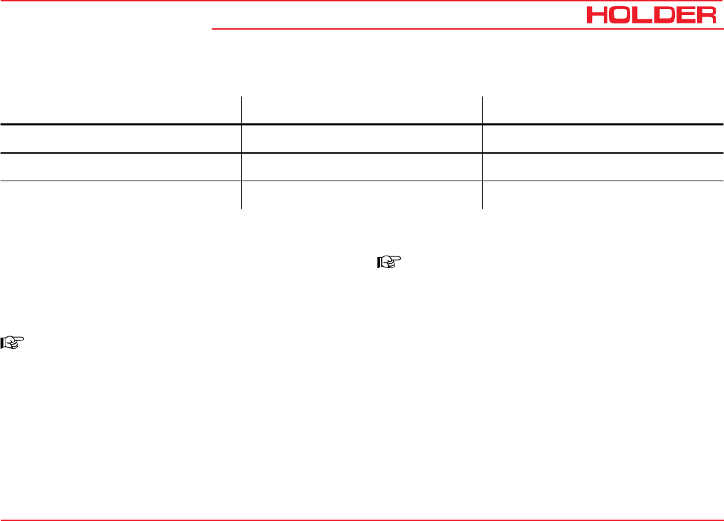
Operating Instructions
145 052 99
C 9700 ... C 9.88 H Operating the Implements
Table of Multi-function Lever Functions (Variant 2)
The functions are selected as follows:
Front Lift 1 - Lifting/Lowering
- Push button I (6). The red LED indicator (5) comes
on.
- Press pushbutton 1 (1).
NOTE
You can also operate the function only
temporarily by pressing lightly.
- The red LED indicator (3) comes on.
- Push the multi-function lever forward.
• The front lift is lowered.
- Pull the multi-function lever back.
• The front lift is lifted.
NOTE
In addition you can also select the float
position*:
- Press the pushbutton (2) blue hydraulic couplings off -
float position.
- LED indicator (3) is illuminated green.
To turn it off, press the pushbutton (1) lightly.
- LED indicator (3) goes off.
- To turn the function off, press pushbutton 0 (4). The
red LED indicator (5) extinguishes.
* Option
Attachment Motion Related Hydraulic Couplings
Front lift 1 Lift - lower Function at blue couplings
Front lift 2 Sideshifting left/right Function at yellow couplings
Front lift 3 Tilting Function at green couplings

C 9700 ... C 9.88 H
Operating Instructions
100 145 052
Operating the Implements
Front Lift 2 - Shifting Left/Right
- Push button I (6). The red LED indicator (5) comes
on.
- Press pushbutton 2 (12).
NOTE
You can also select the function only
temporarily by pressing lightly.
- LED indicator (7) is illuminated red.
- Push the multi-function lever forward
• to move the front lift to the left.
- Pull the multi-function lever back
• to move the front lift to the right.
You can also select the float position:
- Push the multi-function lever fully forward.
- To deselect the float position, pull the lever back.
To turn off, press pushbutton (9) lightly.
- The LED indicator (7) extinguishes.
- To deselect the function, press pushbutton 0 (4).
The red LED indicator (5) extinguishes.
456
7
8
9
10
11
12
1
3
2
Bild_074

Operating Instructions
145 052 101
C 9700 ... C 9.88 H Operating the Implements
Front Lift 3 - Lateral Tilt
- Push button I (6). The red LED indicator (5) comes on.
- Press pushbutton 3 (11).
NOTE
You can also select the function only
temporarily by pressing the button lightly.
- LED indicator (8) is illuminated red.
- Push the multi-function lever forward
• The front lift is tilted to the left.
- Pull the multi-function lever back.
• The front lift is tilted to the right.
In addition you can also select the float position*:
- Push the pushbutton (10) green hydraulic couplings
off - float position.
- LED indicator (8) is illuminated green.
To turn it off, press the pushbutton (11) lightly.
- The LED indicator (8) extinguishes.
- To deselect the function, press pushbutton 0 (4). The
red LED indicator (5) extinguishes.
* Option
456
7
8
9
10
11
12
1
3
2
Bild_074

C 9700 ... C 9.88 H
Operating Instructions
102 145 052
Operating the Implements
Multi-function Lever (Variant 4)
1 Forward direction arrow (illuminated if selected)
2 Reverse direction arrow (illuminated if selected)
3 Forward/reverse selector switch
(left forward - right reverse)
4 Front lift float position pushbutton
5 Multi-function lever
6 Front lift pushbutton
7 Yellow pushbutton, left (front when looking forward)
(movements at yellow hydraulic couplings activated)
8 Yellow pushbutton, right (front when looking forward)
(movement at green hydraulic couplings activated)
Activating Functions (Operation)
Press the desired pushbutton and move the multi-function
lever either forward/back or across, depending upon the
required function.
87
1
6
2
4
5
3
Bild_068
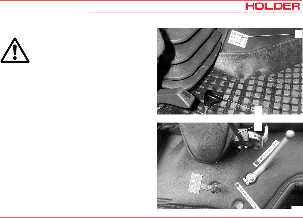
Operating Instructions
145 052 103
C 9700 ... C 9.88 H Operating the Implements
Operating the PTO
DANGER
The PTO clutch lever (3) must be turned off.
To turn it off, it must be put in the horizontal
position.
- Start the engine.
- Select the required PTO rpm with the PTO selector
lever (2).
- To do so, pull the lever to the front and operate it
upwards or downwards.
The possible positions are shown on the plate (1).
- Up position - 540 rpm
- Middle position - OFF
- Down position - 1000 rpm
1
2
3
Bild_087
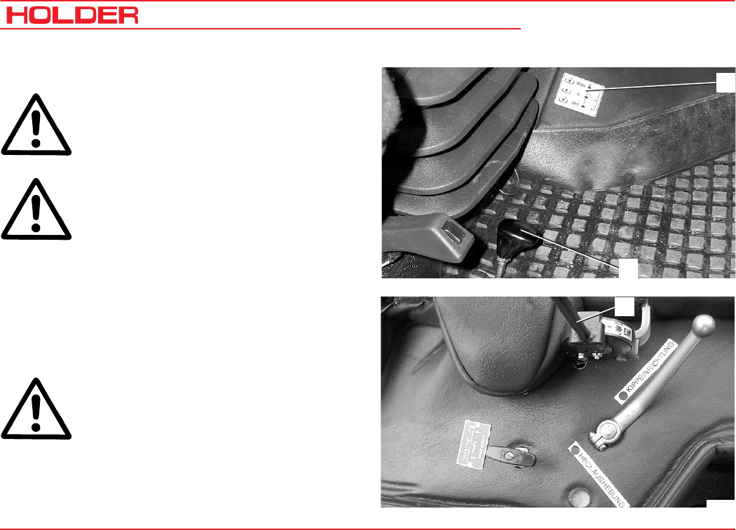
C 9700 ... C 9.88 H
Operating Instructions
104 145 052
Operating the Implements
Engaging the Front PTO
ATTENTION
Never engage the PTO with the engine off.
DANGER
Before engaging the PTO, make sure no-one
is standing close enough to the tractor and
the driven implement to be hurt.
- Pull the PTO clutch lever (3) quickly to the vertical
position. The pressure point must be passed very
noticeably. The front PTO is turned on.
- To disengage it, return the PTO clutch lever to the
horizontal position.
- Return lever (2) to position 0 (neutral).
DANGER
After being disengaged, the installed
equipment can continue to run. Wait until the
equipment is stationary before working on it
again.
3
Bild_087
1
2
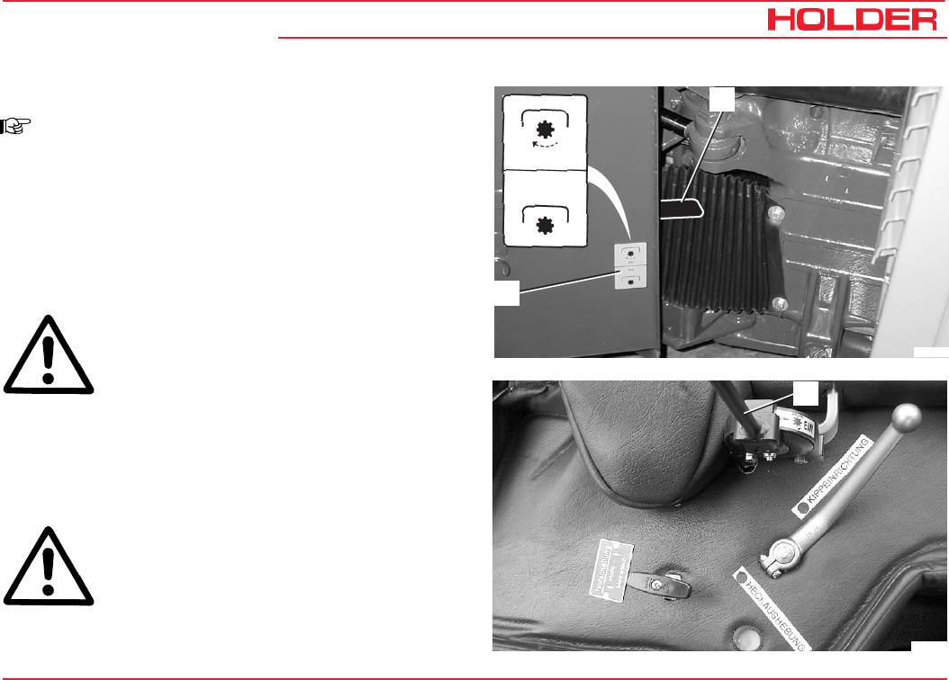
Operating Instructions
145 052 105
C 9700 ... C 9.88 H Operating the Implements
Engaging the Rear PTO
NOTE
The rear PTO can be engaged with PTO
selector lever (4) located at the articulated
joint. The lever positions are shown on the
plate (5).
- PTO selector lever (3) must be turned off.
- Move PTO selector lever (4) up to engage the rear
PTO.
DANGER
Before engaging the PTO, make sure no-one
is standing close enough to the tractor and
the driven implement to be hurt.
- Pull the PTO clutch lever (3) up quickly to the vertical
position. The rear PTO is engaged.
- To disengage it, return the PTO clutch lever to the
horizontal position.
- Push the PTO selector lever (4) down again.
DANGER
After the equipment is turned off, it can still
continue to run. Wait until the equipment is
stationary before working on it again.
Ein
Aus
Bild_090
5
4
3
Bild_087
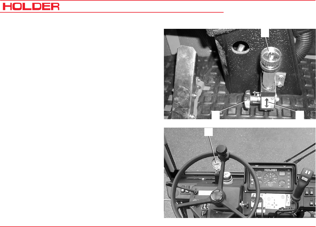
C 9700 ... C 9.88 H
Operating Instructions
106 145 052
Operating the Implements
Operating the Hydraulic Carrier* (Power Lifter)
1 Pressure adjuster
2 ON-OFF plate
3 Star knob for turning on/off
The hydraulic carrier allows for a weight compensation
between implement and tractor. This increases the axle load
and the climbing ability is improved. During road travel with
a lifted implement, the hydraulic system absorbs shocks
due to bumps in the road.
- Turn the star knob (3) to the left (ON position).
- Screw in the pressure adjuster (1) as far as possible.
- Raise the implement with the front lift.
- Read the pressure at the pressure gauge (4) at the
driver's station (eg 100 bar) and select the float
position.
- Screw out the pressure adjuster (1) until the pressure
gauge indicates, for example, 50 bar (implement
resting on ground). The selected pressure corre-
sponds to the carried weight.
- Lower and raise the implement with the front lift.
1
32
4
* Option
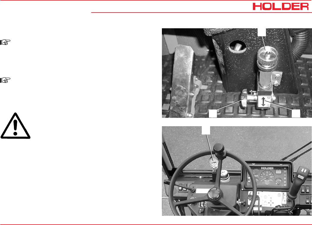
Operating Instructions
145 052 107
C 9700 ... C 9.88 H Operating the Implements
Road Travel with Carrier
NOTE
Do not raise the implement completely to
allow the shock absorption to be effective.
Operation with Carrier
NOTE
If the implement adapts to uneven ground with
delay, turn the pressure adjuster (1) back until
the pressure is reduced.
ATTENTION
On very rough terrain the pressure gauge (4)
may not indicate any pressure at all.
- Raise the implement again with the front lift by opera-
ting it briefly.
- In the case of light implements (eg rotary mower) turn
the carrier off.
- Turn the star knob (3) to the right (OFF position).
1
32
4
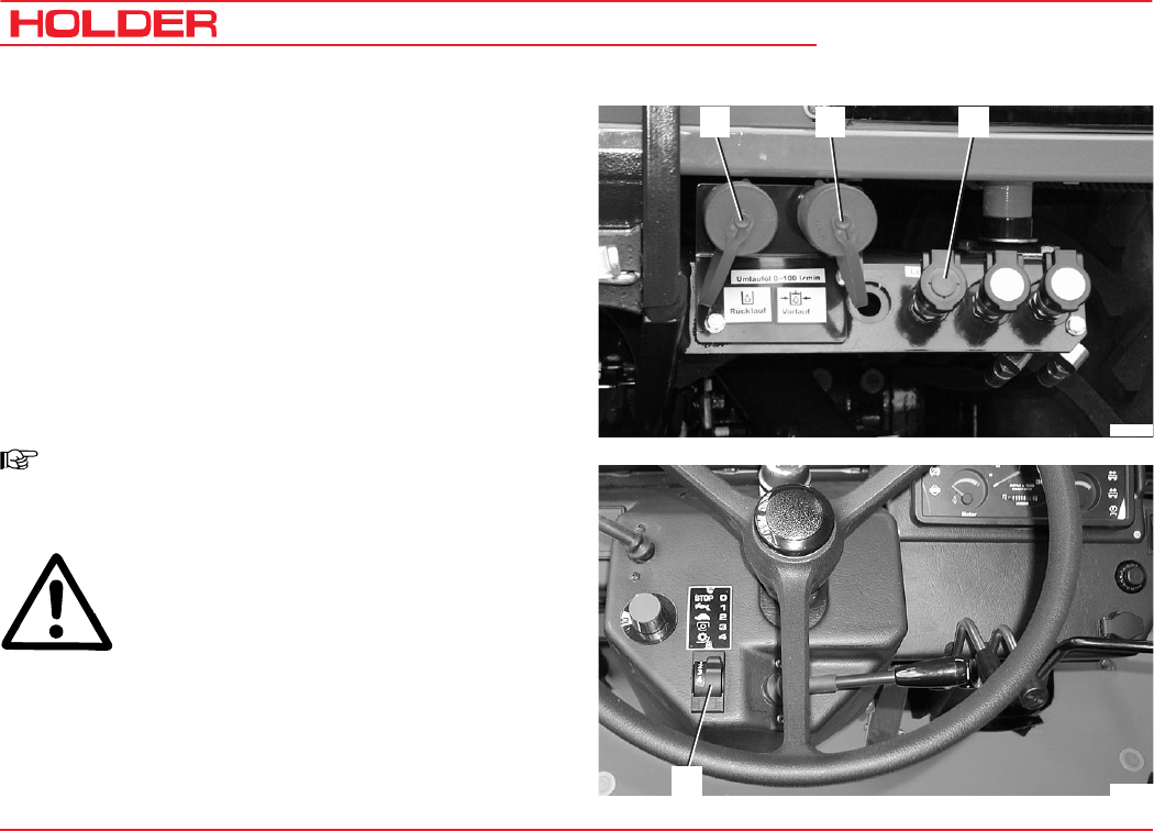
C 9700 ... C 9.88 H
Operating Instructions
108 145 052
Operating the Implements
Operating Variable Pump* for Implements (setting
from 0 to 100 litres)
The variable pump for the implements is a device for driving
attachments with a high hydraulic power demand such as a
spiral-bladed lawn mower. It draws its oil from the working
hydraulics tank with a filling quantity of approx. 45 litres and
is controlled from the driver's station.
- Connect the hydraulic hoses of the implements to the
screw couplings (1) and (2) and the leakage oil cou-
pling (3).
- Set the switch for the driving program (4) to one of the
required driving programs.
NOTE
The variable pump can not be turned on
without a driving program being selected.
ATTENTION
Turn on the starting safety switch (7) only at
low engine speed.
* Option
Bild_092
12 3
Bild_091
4
- Set the rotary knob (5) to 0.
- Release the lock at the starting safety switch (7) and
depress the switch. The indicator in the switch comes on.
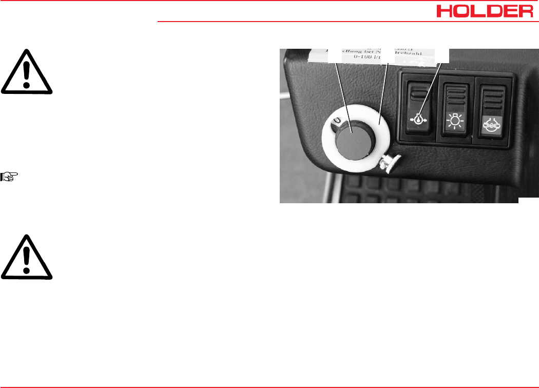
Operating Instructions
145 052 109
C 9700 ... C 9.88 H Operating the Implements
ATTENTION
Increase the engine speed, but then increase
the oil flow only slowly.
- Turn the rotary knob (5) to adjust the oil flow from 0 to
100 litres/min until the desired flow rate for the imple-
ment is reached.
The figure on the ring x10 corresponds roughly to the
oil flow in litres per minutes at full throttle.
NOTE
With the setscrew at the stop ring (6) it is
possible to set a stop so that a certain flow
rate for an implement is not exceeded.
ATTENTION
If the implement is no longer used, turn the
variable pump for implements off with the
starting safety switch to prevent any
unnecessary overheating of the hydraulic oil.
Turning Off the Variable Pump for Implements
- Turn off the starting safety switch (7). The indicator in
the switch extinguishes.
Bild_093
56 7
NOTE: If the variable pump for the implements is not first
switched off when you:
• turn off the engine,
• set the drive program switch to 0,
• started with the forward/reverse selector lever in the
forward or reverse position
you can not, for safety reasons, immediately restart the
variable pump for implements.
Before a renewed start you must either first:
- set the rotary knob to 0, or
- turn the starting safety switch off and on again once, or
- operate the forward/reverse selector lever once through
neutral.
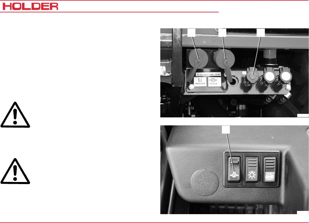
C 9700 ... C 9.88 H
Operating Instructions
110 145 052
Operating the Implements
Operating the Power Hydraulics* ( 75 L Fixed Flow)
The power hydraulic system is used for driving attachments
with a fixed hydraulic power demand. It draws the oil from
the working hydraulics tank and is controlled from the driver's
station.
- Connect the hydraulic hoses of the implement to the
screw couplings (1) and (2) and the leakage oil cou-
pling (3).
ATTENTION
Turn on the starting safety switch only at a
low engine speed.
- Release the lock at the starting safety switch (4) and
depress the switch. The indicator in the switch comes
on.
ATTENTION
Increase the speed of the engine slowly.
- The implement is supplied with an oil flow of approx.
75 l/min.
Bild_092
12 3
Bild_094
4
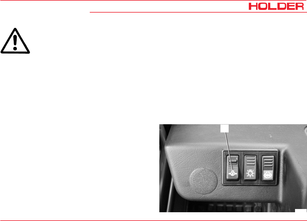
Operating Instructions
145 052 111
C 9700 ... C 9.88 H Operating the Implements
ATTENTION
If the implement is no longer used, turn off
the power hydraulics starting safety switch
to prevent any unnecessary overheating of
the hydraulic oil.
Never leave the power hydraulic system on:
- when the engine is running without a load connected
to the couplings
- or not in operation,
- when driving without needing oil.
The overheating can damage the hydraulic system.
Turning Off the Power Hydraulics
- Turn off the starting safety switch (4). The indicator in
the switch extinguishes.
Bild_094
4
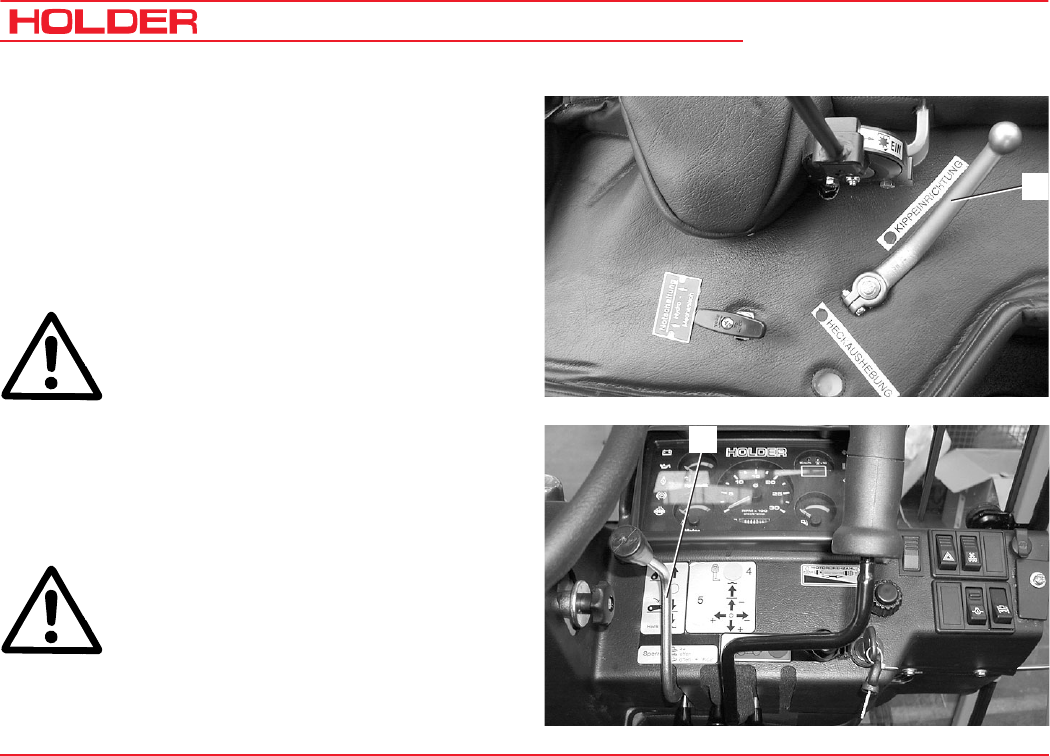
C 9700 ... C 9.88 H
Operating Instructions
112 145 052
Operating the Implements
Operating the Hydraulic Dumper
With the hydraulic dumper it is possible to lift the dump
body fast and easily. The dumper tips the loading platform*
to the rear.
- Start the engine.
Device selector lever:
- Selector lever (1) behind the seat in "dumper" positi-
on.
1
* Option
DANGER
Make sure no-one standing behind the truck
can get hurt.
- Move the implement control lever (2) to the "lift"
position.
• The dumper is lifted. To stop the movement,
release the control lever.
- To lower the dumper, move the implement control
lever (2) to the "lowering" position.
DANGER
Make sure no-one standing behind the truck
can get hurt - danger of being crushed.
The dumper is lowered.
2
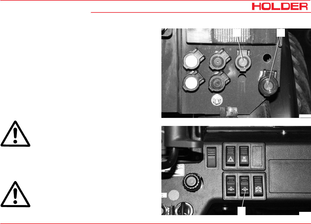
Operating Instructions
145 052 113
C 9700 ... C 9.88 H Operating the Implements
Operating the Oil Circulating Device* (Rear, Unregu-
lated)
The oil circulating device drives the hydraulic motor of an
implement with a fixed hydraulic power demand, for example
a mounted road spreader in winter. It is supplied with oil
from the working hydraulics tank by a tandem pump and
operated from the driver's station. The implement must be
equipped with its own flow regulator.
- Connect the hydraulic hoses of the implement to the
red hydraulic couplings for the drive (1) and return line
(2) at the rear of the tractor.
ATTENTION
Turn on the starting safety switch only at low
engine speed.
- Release the lock at the starting safety switch (3) and
depress the switch. The switch engages and the
indicator in the switch comes on.
ATTENTION
Increase the speed of the engine slowly.
* Option
Bild_116
12
Bild_117
3
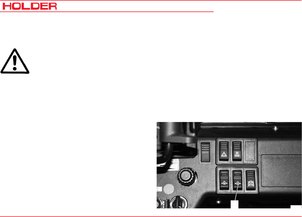
C 9700 ... C 9.88 H
Operating Instructions
114 145 052
Operating the Implements
- The servo motor in the implement is supplied with an
oil flow of max. 35 litres/min at a speed of 2500 rpm.
ATTENTION
If the implement is no longer used, turn the
oil circulating device off with the starting
safety switch to prevent any unnecessary
overheating of the hydraulic oil.
Do not leave oil circulating device on:
- when the engine is running without a load connected
to the couplings
- or not in operation,
- when driving without needing oil.
The overheating can damage the hydraulic system.
Turning off the Oil Circulating Device
- Turn off the starting safety switch (3).
Bild_117
3
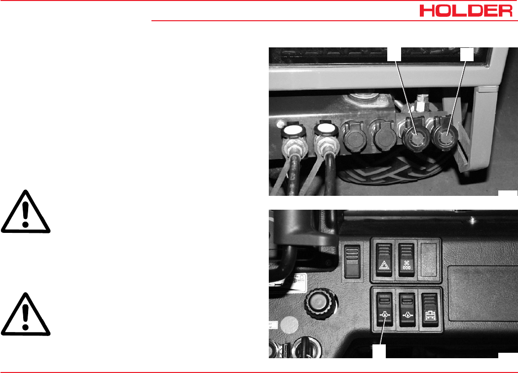
Operating Instructions
145 052 115
C 9700 ... C 9.88 H Operating the Implements
Operating Priority Flow Valve I*
Priority flow valve I is used to drive the servo motor in an
implement with a variable hydraulic power demand, for
example, salt spreader, hedge cutter, etc. The working speed
can be set independently of the tractor engine speed. The
priority flow valve is fed by the standard working pump and
is operated from the driver’s station.
- Connect the hydraulic hoses of the implement to the
red hydraulic couplings for the drive (2) and return line
(1) at the front of the tractor.
ATTENTION
Turn on the starting safety switch only at a
low engine speed.
.
- Release the lock at the starting safety switch (3) and
depress the switch. The switch engages and the
indicator in the switch comes on.
ATTENTION
Increase the speed of the engine slowly.
* Option
Bild_118
12
Bild_119
3
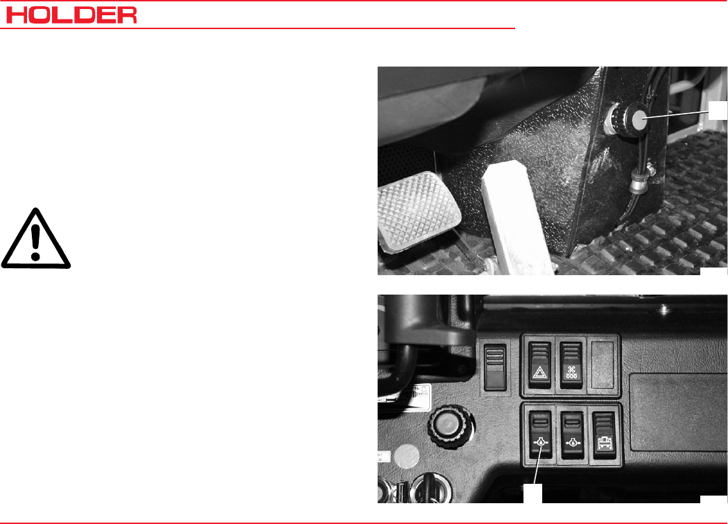
C 9700 ... C 9.88 H
Operating Instructions
116 145 052
Operating the Implements
- Select the desired engine speed with the hand thrott-
le.
- Set the priority valve hand wheel (4) to the working
speed required for the attachment.
Turning counterclockwise increases, turning clockwi-
se lowers the RPM.
- The servo motor in the implement is fed with an oil
flow of 0 to 25 litres/min.
ATTENTION
If the implement is no longer used, turn the
priority flow valve off with the starting safety
switch to prevent any unnecessary overheat-
ing of the hydraulic oil.
Do not leave the priority flow valve on:
- when the engine is running without a load connected
to the couplings
- or not in operation,
- when driving without using oil
The overheating can damage the hydraulic system.
Turning Off the Priority Flow Valve
- Turn off the starting safety switch (3). The indicator in
the switch extinguishes.
Bild_120
4
Bild_119
3
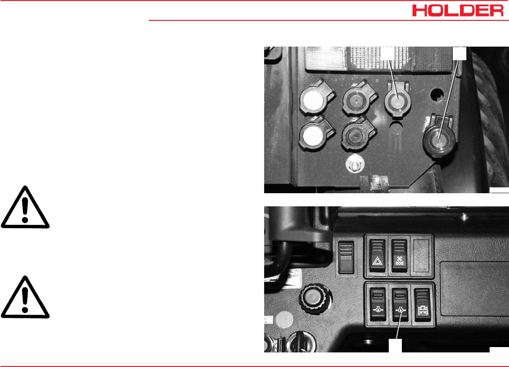
Operating Instructions
145 052 117
C 9700 ... C 9.88 H Operating the Implements
Operating priority flow valve II*
Priority flow valve II is used to drive the servo motor in an
implement with a variable hydraulic power demand, for
example, salt spreader, hedge cutter, etc. The working speed
can be set independently of the tractor engine speed. The
priority flow valve is fed by the tandem working pump and
set at the rear of the tractor.
- Connect the hydraulic hoses of the implement to the
red hydraulic couplings for the drive (1) and return line
(2) at the rear of the tractor.
ATTENTION
Turn on the starting safety switch only at a
low engine speed.
- Release the lock at the starting safety switch (3) and
depress the switch. The switch engages and the
indicator in the switch comes on.
ATTENTION
Increase the speed of the engine slowly.
* Option
Bild_116
12
Bild_117
3
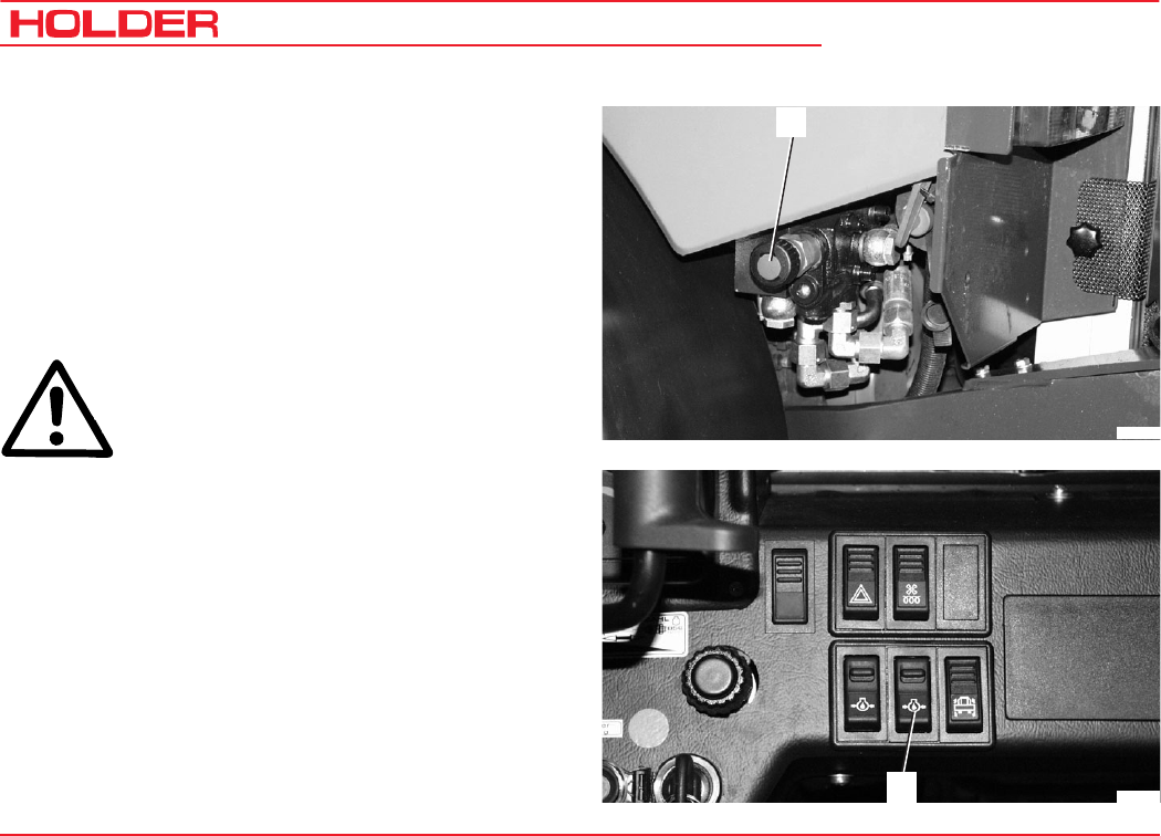
C 9700 ... C 9.88 H
Operating Instructions
118 145 052
Operating the Implements
- Adjust the desired speed of the engine with the hand
throttle.
- Go to the rear of the tractor and adjust the hand wheel
(4) of the priority flow valve to the working speed
required for the implement.
Turning counterclockwise increases, turning clockwi-
se lowers the RPM.
- The servo motor in the implement is fed with an oil
flow of 0 to 25 litres/min.
ATTENTION
If the implement is no longer used, switch
the priority flow valve off with the starting
safety switch to prevent any unnecessary
overheating of the hydraulic oil.
Do not leave the priority flow valve on:
- when the engine is running without a load connected
to the couplings
- or not in operation
- when driving without oil being required
The overheating can damage the hydraulic system.
Turning Off the Priority Flow Valve
- Turn off the starting safety switch (3). The indicator in
the switch extinguishes.
Bild_121
4
Bild_117
3
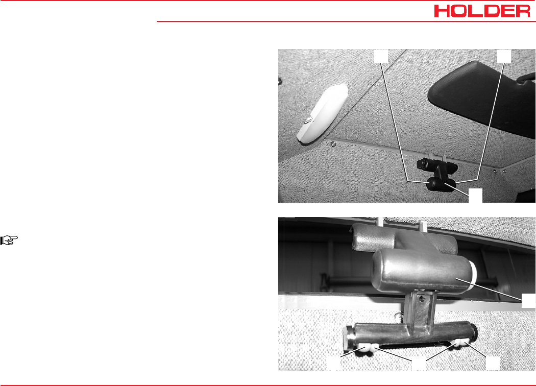
145 052 119
C 9700 ... C 9.88 H Operating Instructions
Other Activities
Operating the Driver's Cab
Operating the roof hatch
Opening the roof hatch
- Press the buttons (1 and 2) on the sides of the handle
together.
- Push the handle (3) up. The roof hatch opens at the
rear.
Removing the roof hatch
NOTE
The roof hatch can be used as an emergency
exit in case of danger.
- Open the roof hatch.
- Press the inner plastic clips (1) in and out.
- Press the outer plastic clips (2) in.
- Swing the roof hatch up with the handle (3) and open
to the front.
1 2
3
12 2
3

C 9700 ... C 9.88 H
Operating Instructions
120 145 052
Other activities
Turning on the Windshield Wiper/Washer
NOTE
The tractor is provided with a front and rear
wiper. A washer system is also installed. The
washer system is supplied with water from
the washing water reservoir below the
passenger seat.
Front Windshield Wiper/Washer
- Set the front windshield washer switch (1) to the 1st
stage.
The front wiper is in operation.
- Set the switch to the 2nd stage:
The front windshield washer is on and only sprays as
long as the switch is actuated.
Rear Wiper/Washer
- Set the rear windshield washer switch (2) to the 1st
stage.
The rear wiper/washer is in operation.
- Set the switch to the 2nd stage:
The rear windshield washer is on and sprays only as
long as the switch is actuated.
Bild_184
12
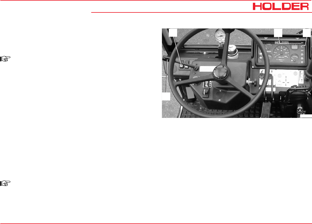
Operating Instructions
145 052 121
C 9700 ... C 9.88 H Other activities
Lights
Turning On and Operating the Lights
NOTE
Turn the preheat/starter switch to position 1.
- Set the light switch (1) to the 1st position.
The front clearance lights (2, 7) and rear tail lights (9,
14) (sidemarker light) are on.
- The position light indicator (2) in the multi-function
display comes on.
- Set the light switch (1) to the 2nd position
The front headlights (1, 8) (dip beam) are on.
Turning On High Beam
- Set the light switch (1) to the 2nd position.
- Move the turn signal lever (4) down. The headlights
(1, 8) are set to high beam.
- The high beam indicator (3) in the multi-function
display comes on.
NOTE
To use the headlight flasher, operate the
signal lever up.
Bild_095
12 3
4
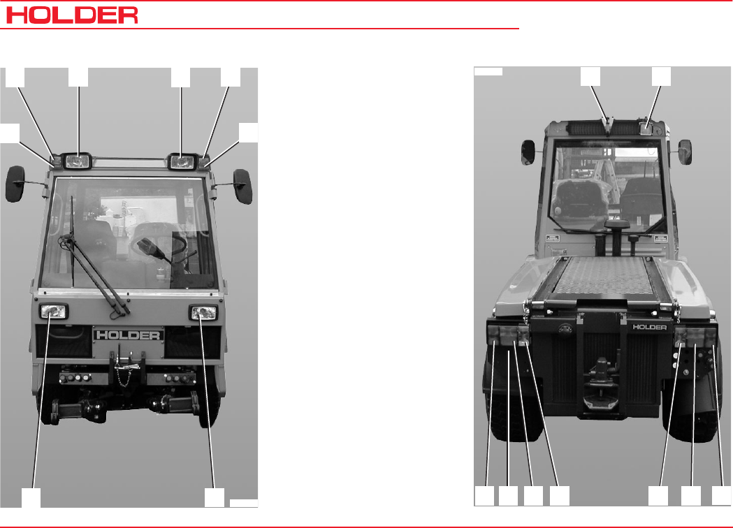
C 9700 ... C 9.88 H
Operating Instructions
122 145 052
Other activities
1 Head light
2 Clearance light, RH
3 Turn signal light, RH
4 Head light, up
5 Head light, up
6 Turn signal light, LH
7 Clearance light, front
8 Headlight, front
9 Stop light
10 Tail light, turn signal
light, LH
11 Reversing light
12 Rotating beacon mount
13 Flood light*
14 Stop light
15 Tail light, turn signal
light, RH
16 Reversing light
17 License plate light
Bild_096
2
3456
7
8
1
Bild_097 12 13
91017 11 16 15 14
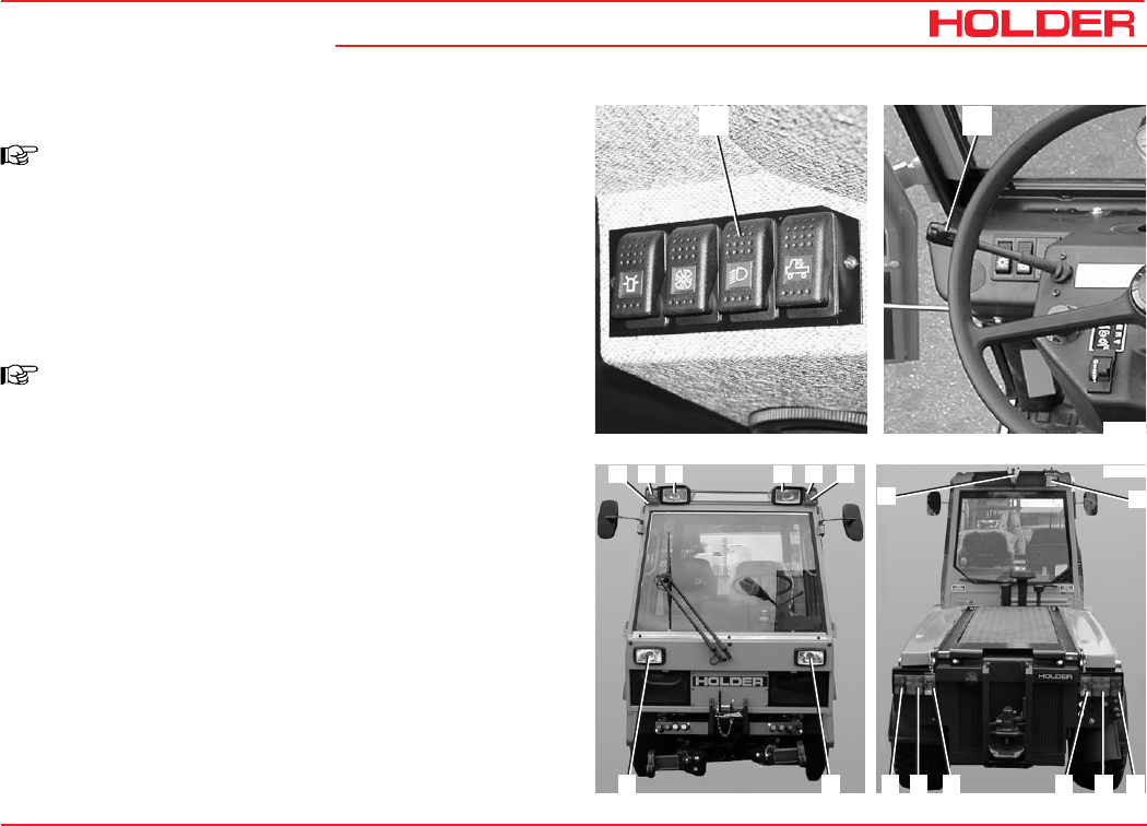
Operating Instructions
145 052 123
C 9700 ... C 9.88 H Other activities
Bild_101
2
10
3 4 56 7
81 911 16 15 14
13
12
1
Bild_10
0
2
Turning on the Upper Lights
NOTE
If front implements are installed and the bottom
headlights are hidden, it is possible to turn on
the upper lights. If these headlights are on,
drive only at a maximum speed of 25 km/h.
- Operate the upper headlights switch (1).
- The upper headlights (4, 5) are on.
NOTE
The functions high beam and headlight flasher
are only available in the lower headlights.
Right and Left Turn Signal
- Set the turn signal lever (2) back. The left turn signal
lights (6, 9) are on.
- The turn signal indicator in the multi-function display
flashes.
- Move the turn signal lever (2) forward. The right turn
signal lights (3, 14) are on.
Operating the Horn
- Push in the turn signal lever (2) to sound the horn.
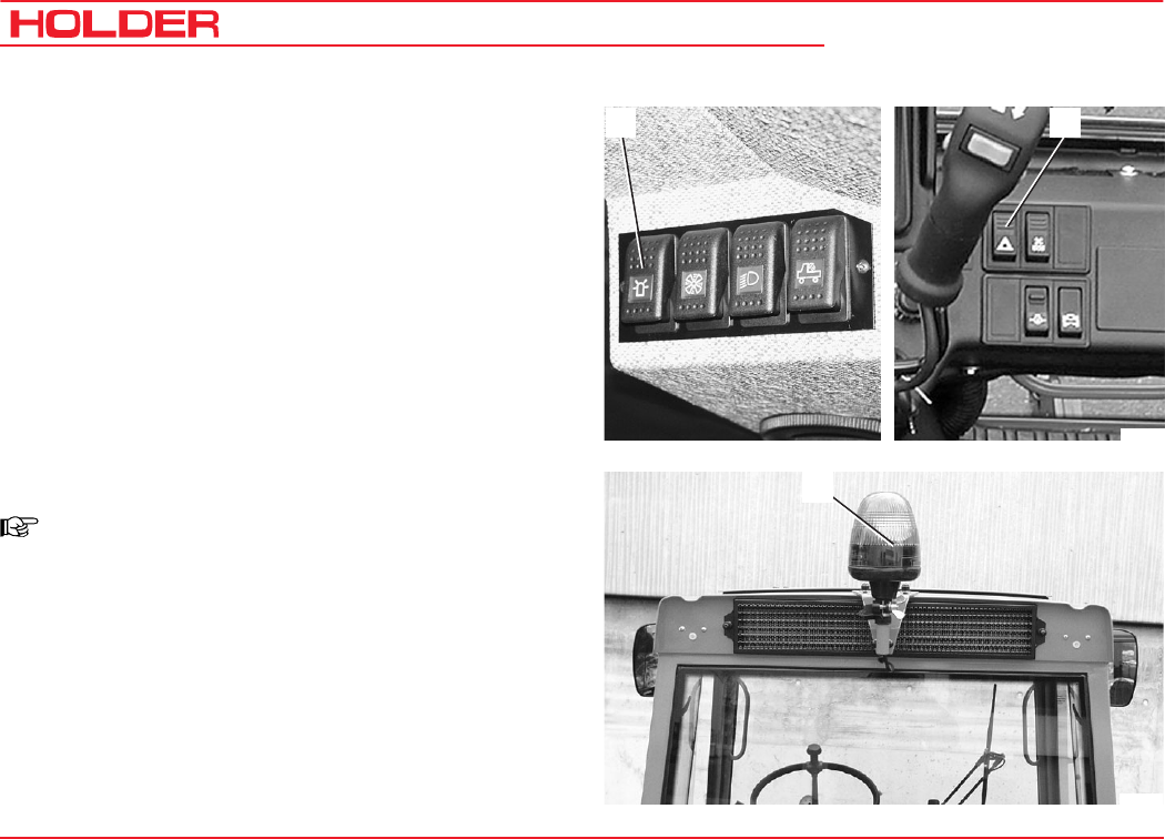
C 9700 ... C 9.88 H
Operating Instructions
124 145 052
Other activities
Turning on the Hazard Warning Flasher System
- Operate the hazard warning flasher switch (2) to turn
on the hazard warning lights.
Turning on the Rotating Beacon*
NOTE
The rotating beacon may only be turned on if
the tractor is used for applications on public
roads.
- Operate the rotating beacon switch (1).
The rotating beacon (12) is on.
* Option
1
Bild_103
2
Bild_102
12
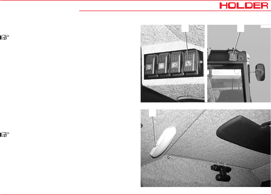
Operating Instructions
145 052 125
C 9700 ... C 9.88 H Other activities
Turning on the Flood Light*
NOTE
The flood light should not be used in the public
traffic area.
- Operate the flood light switch (4).
The flood light (13) is on.
Interior Light
Turning on the Interior Light
NOTE
There is an interior light on the left and right
in the cabin roof.
- To turn on the interior lights, move the switch (1)
forward.
1
* Option
Bild_104
13
4
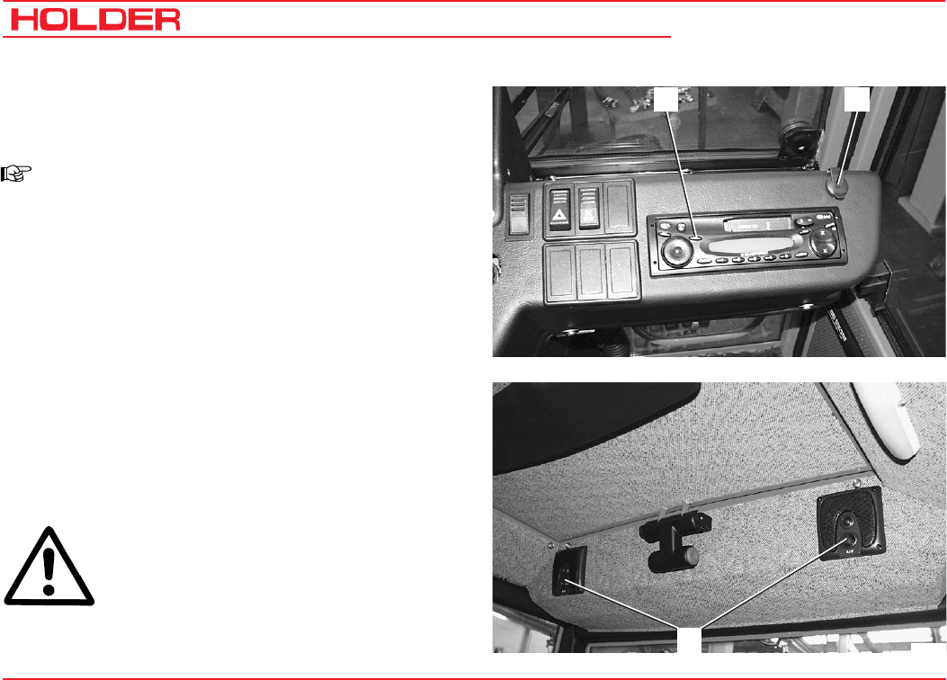
C 9700 ... C 9.88 H
Operating Instructions
126 145 052
Other activities
1 2
3Bild_042
Radio* and Loudspeaker*
Operating the Radio
NOTE
There is a separate operating manual for the
radio (1).
Please observe the instructions in this manual for operation
of the radio.
The loudspeakers (3) are installed at the rear in the roof of
the cabin.
Power Socket
Connecting Equipment to Power Socket
- You can connect 12 VDC equipment with maximum
power rating of 15 A to the power socket (2) with a
commercial automotive plug.
ATTENTION
Do not leave the equipment running unat-
tended; If the engine is not running, the bat-
tery can be discharged.
* Option
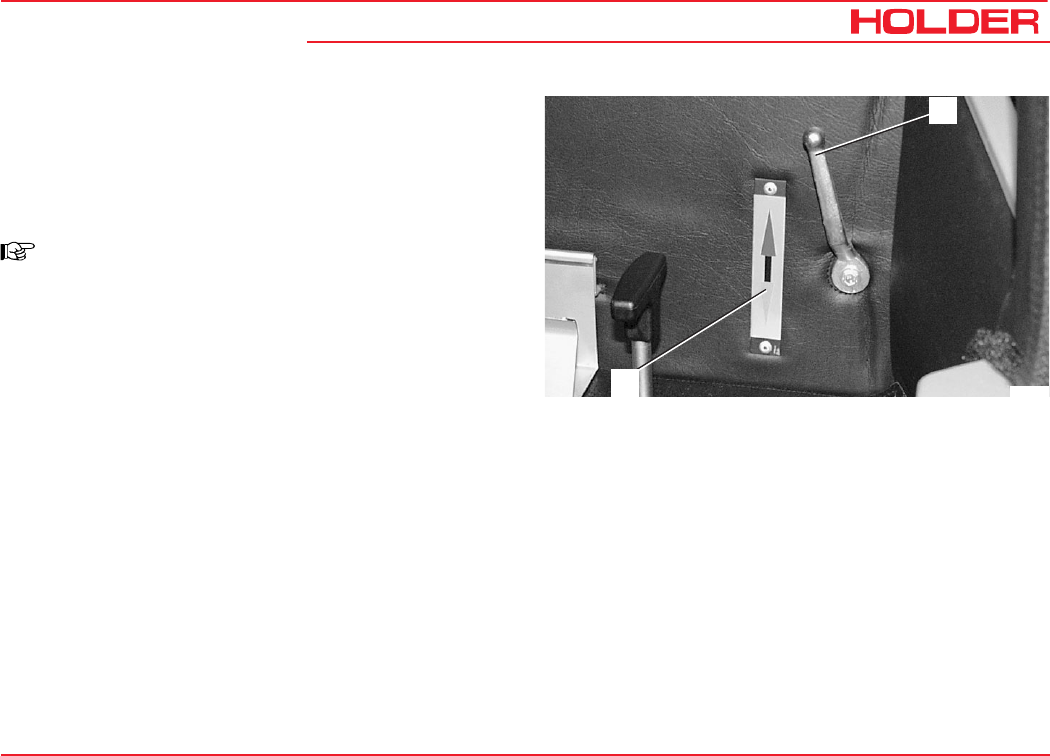
Operating Instructions
145 052 127
C 9700 ... C 9.88 H Other activities
Heating
Heating and Ventilation
Turning on the Heating
NOTE
The cabin heater is heated by the engine
cooling oil.
- To heat the cabin, turn the heat shut-off valve (1) up.
Any intermediate position is also possible. Lever up
increases the heating effect, lever down reduces it.
Observe the plate (2) beside the heat shut-off valve.
- To shut the heating off, move heat shut-off valve
lever fully down.
1
2Bild_009
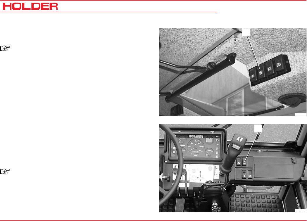
C 9700 ... C 9.88 H
Operating Instructions
128 145 052
Other activities
- To heat the cabin, toggle the heater blower switch
(2).
NOTE
The heater blower has two speeds.
- Position 1 Slow (only air circulation in the cabin)
- Position 2 Fast (heater blower at high speed,
roof blower at slow speed)
There are several air vent nozzles fitted in the cabin:
- 2 in the cab roof at the front
- 1 behind the driver's seat
- 4 at the instrument panel for the front and side windows
- 2 low down at the front in the foot area
- Set the air vent nozzles to the desired direction and
desired air flow.
Turning on the Ventilation System
- To ventilate the cabin, operate the fresh air blower
switch (1).
NOTE
The fresh air blower (top) has 2 speeds.
- Position 1 Slow
- Position 2 Fast (for summer)
1
Bild_04
4
2
Bild_045
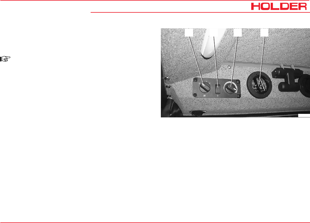
Operating Instructions
145 052 129
C 9700 ... C 9.88 H Other activities
Air Conditioner
Operating the Air Conditioner*
NOTE
A separate operating manual is supplied for
the air conditioning.
Please observe the instructions in this manual for operation
of the air conditioning.
The air conditioner is protected with its own 25 A fuse
located in the compartment at the left behind the cabin.
Air Conditioning*
1 Switch for 4-speed blower
2 On/Off switch
3 Temperature control
4 Air vent nozzle, adjustable
- Set the air vent nozzles to the desired direction and
to the desired air flow.
1 2 3 4
Bild_046
* Option
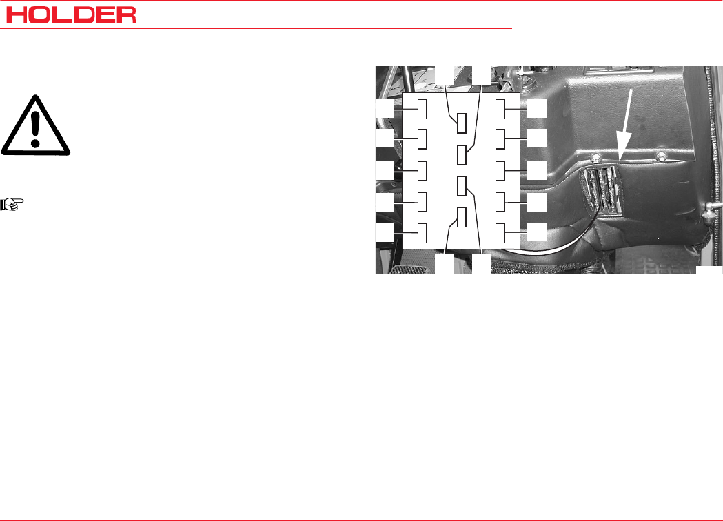
C 9700 ... C 9.88 H
Operating Instructions
130 145 052
Other activities
Fuses
CAUTION
Before carrying out any work on the electrical
equipment, for example, replacing the fuses,
always turn the battery isolating switch off.
Fuses for the Tractor
NOTE
The fuses for the tractor are installed below
the instrument panel at the right-hand side.
To gain access to the fuses, remove the
cover.
1 Hazard warning flasher system
Cab interior light /radio 30/cigarette lighter
2 Sidemarker light 58R/multi-function display light
3 Sidemarker light 58L, auxiliary lighting
4 Dip beam
5 High beam/high beam indicator
6 Stop light
7 Optional light switch/pressurizing valve
diff. lock/headlight flasher
8 Heater blower motor
9 Digital display for driving speed/PTO
10 Solenoid valve for circulating oil/multi-function
display 15
11 Horn/engine shutdown solenoid via relay 72
12 2-pole socket/radio/cigarette lighter/
electric seat adjuster
13 Turn signal lights
14 Electronics box 15 Hydrostatic
drive forward/reverse switch
1515151515
2015151515
15151515
14 13
11 12
6
7
8
9
10
1
2
3
4
5
Bild_047
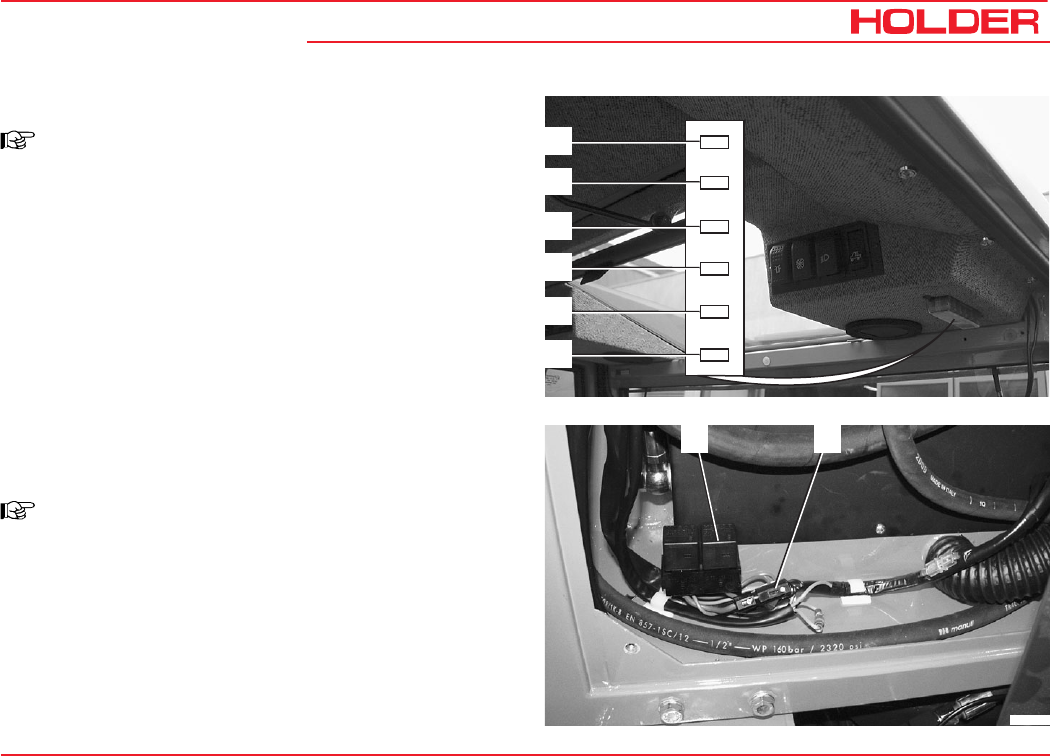
Operating Instructions
145 052 131
C 9700 ... C 9.88 H Other activities
Fuses for the Cabin
NOTE
The fuses for the cabin are located on the
console at the top right.
To gain access to the fuses, remove the
cover.
Fuses for the Cabin
1 Right and left interior light, 15 A
2 Rear wiper/washer system 15 A
3 Front wiper/washer system 15 A
4 Flood light 15 A
5 Fresh air blower 15 A
6 Rotating beacon 25 A
Fuse for Air Conditioning*
NOTE
In the compartment at the left behind the
cabin.
To gain access to the fuses, screw off the
cover on the left behind the cabin.
1 Fuse 25 A
2 Air conditioner relay
15
15
15
15
15
25
1
2
3
4
5
6
* Option
Bild_185
2 1
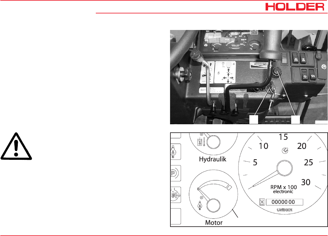
145 052 133
C 9700 ... C 9.88 H Operating Instructions
Taking out of Operation
Leaving the Tractor
Stopping the Tractor
- Lower the implement completely.
- Engage the parking brake.
- Push in the hand throttle (1) fully (idle position).
- Set the forward/reverse selector lever to 0.
- Set the drive program switch to 0.
1Bild_114
2
ATTENTION
If the engine is overheated (engine tempera-
ture gauge (3) in the red field), let the engine
run without a load until the temperature has
dropped to the green area. Do not let the en-
gine run unattended!
3Bild_115
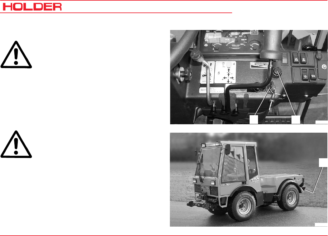
C 9700 ... C 9.88 H
Operating Instructions
134 145 052
Taking out of Operation
Parking
ATTENTION
If the tractor is parked on slopes, it must be
secured against rolling with chocks.
- Put the tractor in a low gear (only if equipped with a
gearbox).
- If equipped with a hydrostatic drive, also secure the
tractor with chocks.
- Turn the ignition key (2) to the left to 0 to turn the
engine off.
- Remove the ignition key and take it along.
CAUTION
Do not leave the cabin without taking the
ignition key.
- Turn off the battery isolating switch (3) and take the
key with you.
Leaving the Tractor
- Lock the cab door(s) with the key.
- If necessary, secure the tractor against rolling with
chocks.
Bild_111
3
1Bild_114
2

145 052 135
C 9700 ... C 9.88 H Operating Instructions
Trailers, Towing
Your tractor can tow the following trailers:
Table of Trailers
NOTE: A pneumatic braking system is available as option.
The following trailer combinations are allowed:
1 Tractor plus single-axle trailer with brake or without brake
2 Tractor plus single-axle trailer with brake or without brake plus two-axle trailer with override brake.
3 Tractor plus two-axle trailer with brake plus two-axle trailer with override brake.
4 Tractor plus two trailers with override brakes, plus single-axle trailer plus two-axle trailer, or two-axle trailer plus two-
axle trailer
NOTE: The total length of the tractor-trailer train should not exceed 18 m.
Type of Trailer Permissible Total Weight Braking System
Single axle trailer 2.5 t No braking system
Single and multiple axle trailer Up to 4 tons
With own braking system if the trailer brake lever
can be mounted easily accessible beside the
driver's seat
Single axle tailer Up to 4.5 tons With overrunning brake
Multiple axle trailer Up to 4.5 tons With service brake system and parking and rapid-
emergency brake
Trailer Up to 12 tons With hydraulic or pneumatic braking system
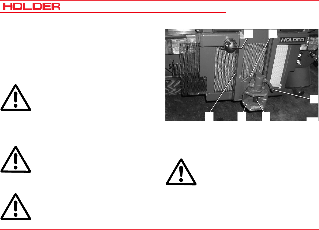
C 9700 ... C 9.88 H
Operating Instructions
136 145 052
Trailers, Towing
- Drive the tractor with the hitch in the trailer tiller.
Upon contact, the hitch closes, the towing pin (3)
goes through the eye of the tiller.
DANGER
The trailer hitch must be completely closed.
- Connect the trailer lighting to the socket (5).
- Remove the wheel chocks from the trailers.
Operating the Trailer Hitch, Attaching Trailers
- Adjust the height of the trailer hitch (2) at the adjust-
ment rail (1) so that the trailer tiller can be attached
horizontally.
- To adjust the height, pull the lever (6) up.
Bearing Load
ATTENTION: The bearing load must be at least
25 kg (4 % of the trailer load), while the maximum
bearing load must not exceed 800 kg.
If the bearing load is underrun or exceeded
when unloading the trailer, the load must be
shifted so that the bearing load returns to the
permissible range.
- Drive the tractor in front of the trailer to be attached.
DANGER: The trailer must be secured against
unintentional movement (rolling).
- Pull the release lever (4) up until the tow pin (3) is
clear of the hitch.
DANGER
Be sure no-one is standing between the
tractor and trailer.
Bild_105
5
4
3
2
1
6

Operating Instructions
145 052 137
C 9700 ... C 9.88 H Trailers, Towing
Driving with Trailers
- Set the driving range pre-selection lever (1) to position
S or L. The tractive force is greater in position L.
- Drive the tractor as described in the section on
driving.
DANGER
If a trailer not requiring a permit is attached,
the driving speed is limited to 25 km/h. The
trailer must be identified with a 25 km/h sign.
1
Bild_110
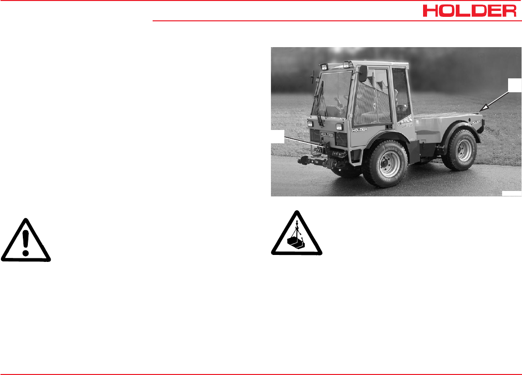
145 052 139
C 9700 ... C 9.88 H Operating Instructions
Transport, Loading, Towing
Instructions for Transport
- Drive the tractor on the means of transport.
- Park the tractor as described in the section on leaving
the tractor.
- Secure the tractor against rolling with chocks at the
wheels and, if needed, with wood blocks at the side to
prevent it from sliding to the side.
- Lash the tractor at the front to the upper link support
(1), at the rear to the towing device (2).
Instructions for Loading
DANGER
When hoisting the tractor, only use lifting
equipment and a crane with a sufficient load
capacity.
- The hoisting weight should not exceed the permissible
total weight:
The hoisting weight is given on the tractor identification plates
or in the tables of weights in the Technical Data.
- Hoist the tractor only with the lifting equipment atta-
ched to all 4 wheels.
DANGER: Do not step or stand under a
suspended load. Danger of loss of life!
1
Bild_112
2
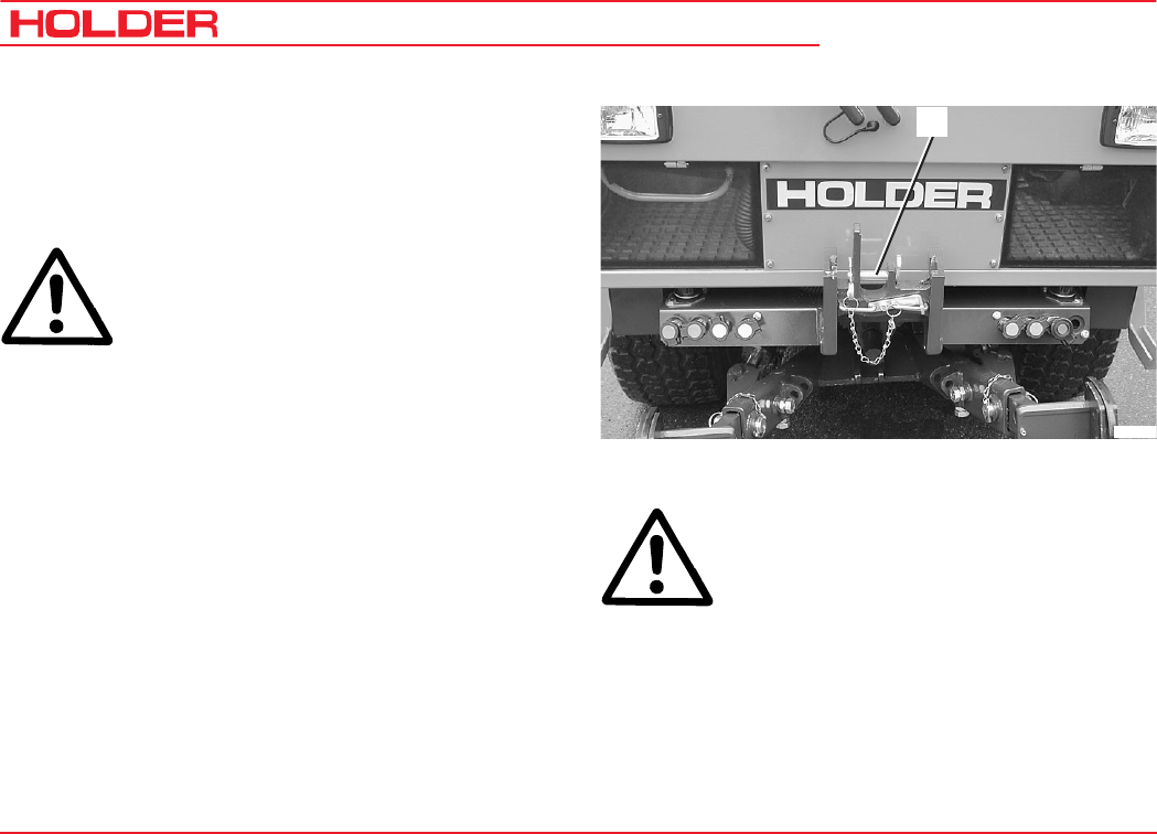
C 9700 ... C 9.88 H
Operating Instructions
140 145 052
Transport, hoisting, towing
Instructions for Towing
If your tractor can not drive on its own power because it is
damaged, it can be towed. Use the upper link support at the
front at the driver's cab for towing.
DANGER: The towing tractor must have
sufficient tractive and braking force for the
towed load without brakes.
- The towed load must not exceed the permissible total
weight.
The total weight of the vehicle is given on the identifi-
cation plate or in the tables of weights in the technical
data.
- Attach the towing device (in case of failure of the
brake only a rigid tow bar) to the upper link support
(1).
- Set the forward/reverse selector lever to the centre
position (no direction of travel selected).
- Shift the gear and range selector lever to neutral
(gearbox).
- Set the driving range pre-selection lever to position 0
(hydrostatic drive).
- Let the engine run so that the power steering is
operational.
CAUTION : If the engine is not running during
towing or the hydraulic system has failed,
steering is difficult. Increased effort is
required for steering in this case.
- Tow the tractor at a maximum of 10 km/h to the
nearest authorized workshop.
- Park the tractor secured against rolling.
Bild_099
1

145 052 141
C 9700 ... C 9.88 H Operating Instructions
Indicators, Adjustments
Adjusting the Speedometer
The adjustment of the speedometer in the multi-function
display is required when changing from large to small tires
and vice versa.
Please refer to the maintenance manual for the adjustment
of the speedometer.

145 052 143
C 9700 ... C 9.88 H Operating Instructions
Problems, Cause, Remedy
The following tables list problems and their possible causes.
If you can not carry out the remedy yourself, please contact
an authorized workshop or our customer service.
Test and Control Box BB3, with which further troubleshooting/
diagnostics are possible, are available as option.
Problems in Engine and Exhaust Gas Turbo-
charger
Please observe the notices in the operating manual for the
engine.
Problems in Electronic and Hydraulic Drive
System
Malfunction Cause Remedy
Tractive force too low Feed pressure too low
High pressure too low
Variable pump or variable motor
leakage too large
Check valve!
Check high pressure valves
Repair variable pump or variable motor
No forward or reverse travel possible Drive or power take-off defective
No feed pressure
Control cylinder in variable pump stuck
Repair
Check feed pump
Replace variable pump

C 9700 ... C 9.88 H
Operating Instructions
144 145 052
Malfunctions, cause, remedy
Problem Cause Remedy
No forward and reverse travel. Range selector lever in neutral
Forward/reverse selector switch in
neutral
No power supplied to the electronics
Electrical connections to variable
pump interrupted
Electrical connection of Diesel engine -
speed sensor interrupted, possibly
oxidized
Accelerator potentiometer defective
Diesel engine speed sensor defective
Forward/reverse selector switch
defective
Drive program switch at 0
Select working or transport range
Put forward/reverse selector switch in
desired direction of travel
Check fuses
Check electrical connection
Make connection
Make connection
Renew accelerator potentiometer
and adjust with BB3
Replace sensor
Replace Forward/reverse selector
switch
Select desired driving program

Operating Instructions
145 052 145
C 9700 ... C 9.88 H Malfunctions, cause, remedy
Problem Cause Remedy
Tractor drives only in one direction Forward/reverse selector switch
defective
Electrical connection to the variable
pump interrupted
Replace forward/reverse selector
switch
Make connection
No maximum speed Diesel engine does not attain
maximum RPM
Inch pedal not at maximum speed
Variable pump not at full delivery
Sensor for ground speed defective,
adjust electrical connection if
required
Check accelerator linkage
Check Diesel engine
Adjust inch pedal and/or inch pot,
calibrate
Check maximal current
Check proportional solenoid
Check or replace sensor, check
electrical connection
Does not remain stationary when
inch pedal is fully depressed
Inch pedal at wrong position, maybe
foreign objects in actuator
Inch pot not adjusted properly
Adjust properly, remove any foreign
objects
Adjust inch pot, calibrate

C 9700 ... C 9.88 H
Operating Instructions
146 145 052
Malfunctions, cause, remedy
Problem Cause Remedy
Inch pedal not functioning Inch pot defective Replace inch pot, calibrate
Repair cable connection
Tractor does not remain stationary in
driving program 1 or 2 without
operation of accelerator
Idling speed of the engine too high.
(reaches starting RPM)
Incorrect calibration
Adjust idling speed, check actuator
Carry out calibration

Operating Instructions
145 052 147
C 9700 ... C 9.88 H Malfunctions, cause, remedy
Problems in the Hydraulic System and
Steering
NOTE
These notices only apply for valve arrange-
ments conforming to our circuit diagrams or
approved by Bucher.
Problem Cause Remedy
Lifter or hydraulic cylinders not lifting,
although control valve can be moved
normally. No build-up of pressure
(steering working normally)
Pressure relief valve jammed due to
foreign objects
Remove and clean pressure
limitation valve LU 08 SCS-OM2,
but do not change the pressure
setting!
Loss of lifting power Pressure setting too low
Oil level too low
Reset pressure with pressure gauge
(190 bar)
Fill up specified type of oil
Operating pressure is only reached
with high RPM
Pump defective Replace pump
Manual control valve jammed Radial torsion
Dirt
Tension screws too tight or not all
tightened to the same torque
Maximum torque 25 Nm (2.5 mkp)
Remove and clean valve

C 9700 ... C 9.88 H
Operating Instructions
148 145 052
Malfunctions, cause, remedy
Problem Cause Remedy
Hydraulic oil heats too quickly,
system works against excess
pressure
(engine under load)
Control valve jammed.
Control lever remains in operated
position
(Does not automatically return to
neutral position)
Cylinder at limit stop
No implement attached, but control
lever operated (coupling)
Adjust as above
Put valve in neutral position (free
circulation)
Put valve in neutral position (free
circulation)
Hydraulic oil foams Leaks in the suction range Check all pipe connections and
tighten, if required
Hydraulic system working too slowly,
accompanied by whistling noise
Hydraulic oil level too low
Temperatures too low
Fill up as specified
Replace with proper type of oil as
specified in maintenance manual
Steering not working Priority flow valve dirty
Relief valve in hydraulic steering not
closing
Remove the priority flow valve at the
steering and clean it
Remove and clean (authorized
workshop)
Lost steering motion when steering
direction is changed rapidly
Leaks in steering return line Tighten return flow hose

Operating Instructions
145 052 149
C 9700 ... C 9.88 H
General Remarks on Maintenance
To keep your tractor always in peak condition, we would
ask you to study the information in this maintenance manual
very carefully. These chapters contain all the information
you need for a conscientious treatment and care of the tractor.
Take care to have your tractor serviced at the proper
intervals.
Service
Please have all scheduled tractor services (acc. to
maintenance schedule) and repairs carried out regularly by
your dealer (authorized workshop) and confirmed with a
stamp and signature in this maintenance manual.
Detach the double guarantee card filled in by the dealer signed
by the customer directly to
Gebrüder Holder GmbH
P. O. Box 15 55
72545 Metzingen/Württ.
Warranty and product liability can only be claimed if the
maintenance services and inspections have been carried
out punctually and regularly.
Qualification of the Service Personnel
The tractor, together with its attachments, may only be used,
serviced and repaired by persons familiar with this equipment
and have been warned of possible risks.
The qualified personnel entrusted with the work must have
the required tools.
The applicable safety regulations and rules must be
observed.
How to Value the Tractor?
As you know, a car is judged by its age together with the
number of kilometres driven. The way to judge a tractor is to
consider its age together with the number of service hours
according to the following table:
Service Hours Kilometers Driven
1 50
10 500
150 7500
300 15000
600 30000
1500 75000

C 9700 ... C 9.88 H
Operating Instructions
150 145 052
General Remarks on Maintenance
Service
The following services were carried out:
In the maintenance table below you can enter the properly
carried-out services and inspections and have them
confirmed.
(These entries are required to keep your warranty claims
intact):
Service
Interval
Hours of
Operation Date Signature
125
250
375
500
625
750
875
1000
1125
1250
1375
1500
Service
Interval
Hours of
Operation Date Signature
1625
1750
1875
2000
2125
2250
2375
2500
2625
2750
2875
3000

Operating Instructions
145 052 151
C 9700 ... C 9.88 H General Remarks on Maintenance
Handling fuels and lubricants
• Fuels and lubricants must always be handled properly
and as specified by the manufacturer.
• Fuels and lubricants may only be stored in approved
containers at specified places of storage. They can be
inflammable, therefore do not allow them to come in
contact with hot objects or with naked flames.
• Exercise caution when handling fuels - increased dan-
ger of fire. Do not fill any fuels in the vicinity of naked
flames, ignition sparks or hot engine parts. No smoking
when refuelling!
• Before refuelling, shut off the engine and remove the
ignition key. Do not run the engine in enclosed spaces.
Do not spill fuels! (use suitable filling aids).
• Exercise caution when handling brake fluid and battery
acid (poisonous and corrosive).
• Only use clean vessels when filling fuels and lubricants.
• When using fuels, lubricants and cleaners, follow the
safety and disposal instructions of the manufacturer.
• Always avoid spilling. Eliminate spilled brake fluid
immediately with a suitable binding agent and discard
as specified by regulations.
• Oils, fuels, batteries, brake fluid and filters must be
disposed of separately and as specified by regulations.
• Before beginning lubrication, changing filter or opening
the hydraulic system, clean the area surrounding the
affected part carefully.
• Replaced parts must be discarded in a way friendly to
the environment.
• Observe all local and national laws and regulations.
CAUTION
The penetration of hydraulic oil under pressure
into the skin, eg through leaks, is dangerous.
If such injuries occur, seek medical aid.
Safety Notes for Maintenance
Observe the instructions in this maintenance manual and
the general applicable safety and accident prevention rules!
• Do not allow anyone to stand around where they might
get hurt!
• When starting the engine, the traction and implement
drive must be shut off!
• Start the engine only from the driver's station. Do not
start the engine by short circuiting the starter terminals,
as the machine could start moving immediately.

C 9700 ... C 9.88 H
Operating Instructions
152 145 052
General Remarks on Maintenance
• Do not run engine in enclosed spaces! Danger of
poisoning!
• To prevent the danger of fire, keep the tractor and
implements clean!
• When leaving the tractor, secure it against rolling and
unauthorized use (parking brake, chocks), stop the
engine, remove the ignition key and, if required, lock the
cabin.
• Do not leave the tractor unattended as long as the
engine is still running.
• If external current consumers are connected, eg equip-
ment with solenoid valves, protect them with diodes
against back currents. If not, the traction electronics
could be affected.
• Operate the equipment only if all guards are installed
and in position.
• Install and remove the cardan shaft only with the engine
stationary.
• When working with the PTO shaft, no-one should be
standing in the area of the rotating PTO and cardan
shaft.
• The guards for the cardan shaft and the PTO shaft must
be installed as specified.
• When the cardan shaft is removed, refit the protective
cap on the PTO shaft.
• Do not perform any welding, cutting and grinding work
on carrying and other safety-relevant parts such as
tractor frame, axles, trailer hitch, etc.
• The mounting of tires requires sufficient knowledge and
special mounting tools.
• Only use genuine spare parts or qualitatively equiva-
lent, commercially-available parts. Use the parts in the
list of maintenance parts in the chapter entitled "Mainte-
nance Data".
• Before taking into service and after servicing or repair,
the tractor and the implement must be checked for road
worthiness and operating safety.
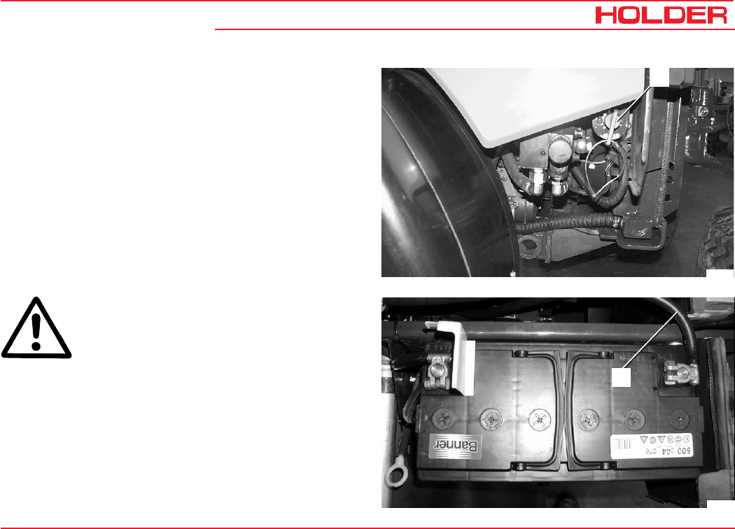
Operating Instructions
145 052 153
C 9700 ... C 9.88 H General Remarks on Maintenance
Work on the Electrical Equipment
Before performing any services on the electrical equipment,
switch off power with the battery isolating switch (1).
- The switch must be horizontal, the toggle removed.
1
Bild_022
Bild_170
2
CAUTION
Disconnect the battery ground lead (2).
Do not place any metal parts on the battery terminals. Risk
of short circuit!
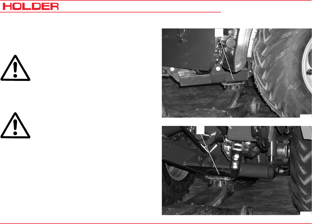
C 9700 ... C 9.88 H
Operating Instructions
154 145 052
General Remarks on Maintenance
Jack Lifting Points
Jacking Up
DANGER
When using the jack, be sure the tractor is
shut down and secured against rolling
(chocks)!
The tractor may only be jacked up at the shown locations (1
and 2).
DANGER
The weight to be lifted should not exceed the
permissible load capacity of the jack.
When carrying out repairs, the raised tractor must also be
secured against lowering with supports. Place the supports
under the axles on both sides.
Bild_123
1
Bild_124
2
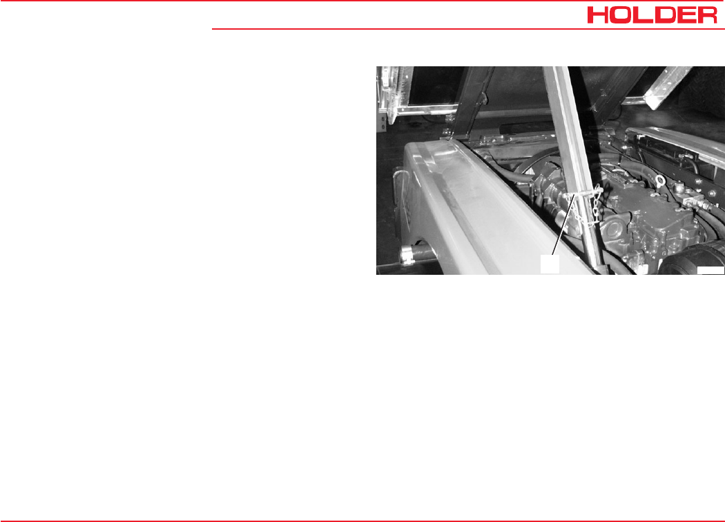
Operating Instructions
145 052 155
C 9700 ... C 9.88 H General Remarks on Maintenance
Securing the Frame (Loading Platform*)
For all services requiring the dump body (loading platform*)
to be raised, secure it against accidental lowering.
- Place a U-channel on the cylinder and secure it with
locking pins (1).
Bild_125
1
* Option

Operating Instructions
145 052 157
C 9700 ... C 9.88 H
Maintenance ScheduleMaintenance Schedule
Maintenance during the First Period of Operation
The services and inspections specified below must be carried
out after the stated number of service hours is reached. The
services and inspections of the lower intervals must be carried
out at the same time.
Example:
At 1000 hours of operation, the services and inspections
for 500 and 125 service hours must also be carried out.
Interval Service and Inspection See page
Maintenance after the first 50
service hours
Check engine for leaks
Check hydraulic oil level
Renew hydraulic oil filter (pressure filter for implement hydraulics)
Renew hydraulic oil filter (pressure filter for drive hydraulics)
Check clutch
Check brake system
Lubricate tractor
Retighten screws and studs
Retighten wheel nuts
161
50
180
179
172
172
173, 185
174
174
Maintenance after the first 150
service hours
Change gear oil of front gearbox
Change gear oil of rear gearbox
187
189
Maintenance after the first 500
service hours
Change hydraulic oil for drive hydraulics
Change hydraulic oil for implement hydraulics
Check or clean hydraulic oil suction filter of implement hydraulics
Check or clean hydraulic oil suction filter of drive hydraulics
Change hydraulic oil return filter for variable pump
Change hydraulic oil return filter for power hydraulics
191
193
191
194
166
167

C 9700 ... C 9.88 H
Operating Instructions
158 145 052
Maintenance Schedule
Regular Maintenance Service and Inspection
Maintenance as required Adjust speedometer
Check air cleaner system
Change hydraulic oil return filter for variable pump
Change hydraulic oil return filter for power hydraulics
Periodic Maintenance
Maintenance every 125 service hours Check cooling system
Clean cooling system
Check battery and cable connections
Check hydraulic oil level, see page 52
Check high pressure hoses
Check steering cylinder and orbitrol
Check brake fluid level for the foot brake
Check clutch brake fluid level
Check clutch
Check PTO clutch
Check brake system
Lubricate tractor
Retighten screws and studs
Retighten wheel nuts
Check electrical system
Clean fresh air filter
Maintenance every 500 service hours Change engine oil
Change engine oil filter
Check hose couplers for leaks
Change hydraulic oil pressure filter (drive hydraulics)
Change hydraulic oil pressure filter (implement hydraulics)
Check heater

Operating Instructions
145 052 159
C 9700 ... C 9.88 H Maintenance Schedule
Periodic Maintenance Service and Inspection
Maintenance every 1000 service hours Check valve play
Check battery
Check V-belt tension and condition
Change fuel filter
Clean or change star filter of fuel feed pump
Lubricate cardan shaft nipples
Maintenance every 1500 service hours
Change gear oil of front gearbox (including axles)
Change gear oil of the rear transmission (including axles)
Change hydraulic oil for drive hydraulics
Change hydraulic oil for implement hydraulics
Check or clean hydraulic oil suction filter of implement hydraulics
Check or clean hydraulic oil suction filter of drive hydraulics
Change hydraulic oil return filter for variable pump, see page 160
Change hydraulic oil return filter for power hydraulics, see page 161
Maintenance every 3000 service hours Check injection nozzles
Change toothed belt
Annual Maintenance
Examine hydraulic oil samples of implement hydraulics
Change hydraulic oil for drive hydraulics
Maintenance every 2 years
Change hydraulic oil for implement hydraulics

Operating Instructions
145 052 161
C 9700 ... C 9.88 H
Maintenance during the First Period
of Operation
During the first period of operation the following services
and inspections are due:
Maintenance after the First 50 Operating Hours
Maintenance after the First 150 Operating Hours
Maintenance after the First 500 Operating Hours
Maintenance after the First 50 Operating
Hours
Check the Engine for Leaks
- Raise the dump body (loading platform*) and secure
against accidental lowering.
-Check the engine and implements for leaks.
Carry out the other services in accordance with the
maintenance schedule. You can find the description of the
services in the maintenance schedule page reference or in
the alphabetical index.
* Option
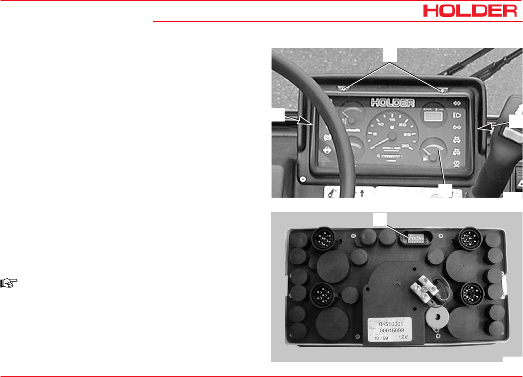
Operating Instructions
145 052 163
C 9700 ... C 9.88 H
Maintenance as Required
Adjusting the Speedometer
The adjustment of the speedometer in the multi-function
display is required when changing from large to smaller tires
and vice versa.
- Remove the sun protection frame (1).
- Disengage the lock on the left (2) and right (3) side of
the frame with a screwdriver.
- Pull the multi-function display (4) out and turn it
around.
- Remove the cover from the combination switch (5) on
the back.
- Set the 6 DIP switches to the positions shown in the
table as required for the size of your tires.
- Note the combinations column applicable for your
display.
NOTE
There are 2 different columns for the possible
combinations. The first column applies for the
tractor with gearbox, the second one for the
Hydrostatic Drive and Dual Drive.
Bild_146
1
3
4
2
Bild_147
5

C 9700 ... C 9.88 H
Operating Instructions
164 145 052
Maintenance as required
- The switches 1 to 6 are set to the positions
1 - up, or
0 - down.
- Refit the multi-function display.
Type Gearbox Hydrostatic Dual Drive
Combination Combination
Switch Arrangement
Tire Size 1 2 3 4 5 6 1 2 3 4 5 6
36x13,5-15 524-31-8 0 1 0 1 1 0 1 0 0 0 0 0
10.5-18 MPT 524-31-1/-6 1 1 0 1 1 0 1 1 0 0 0 0
400/60-15,5 524-31-5 1 0 1 1 1 0 0 1 1 0 0 0
33x12,5 R15 524-31-7 0 0 0 0 0 1 1 0 0 1 0 0
33x12,5-15 524-31-4 1 1 1 1 1 0 1 1 0 1 0 0
33x15,5-15 524-31-3 1 1 1 1 1 0 1 1 0 1 0 0
33/18 LL-16.1 524-31-9 1 1 1 1 1 0 1 1 1 1 1 0
31x15,5-15 524-31-2 1 0 0 0 0 1 0 0 1 1 0 0
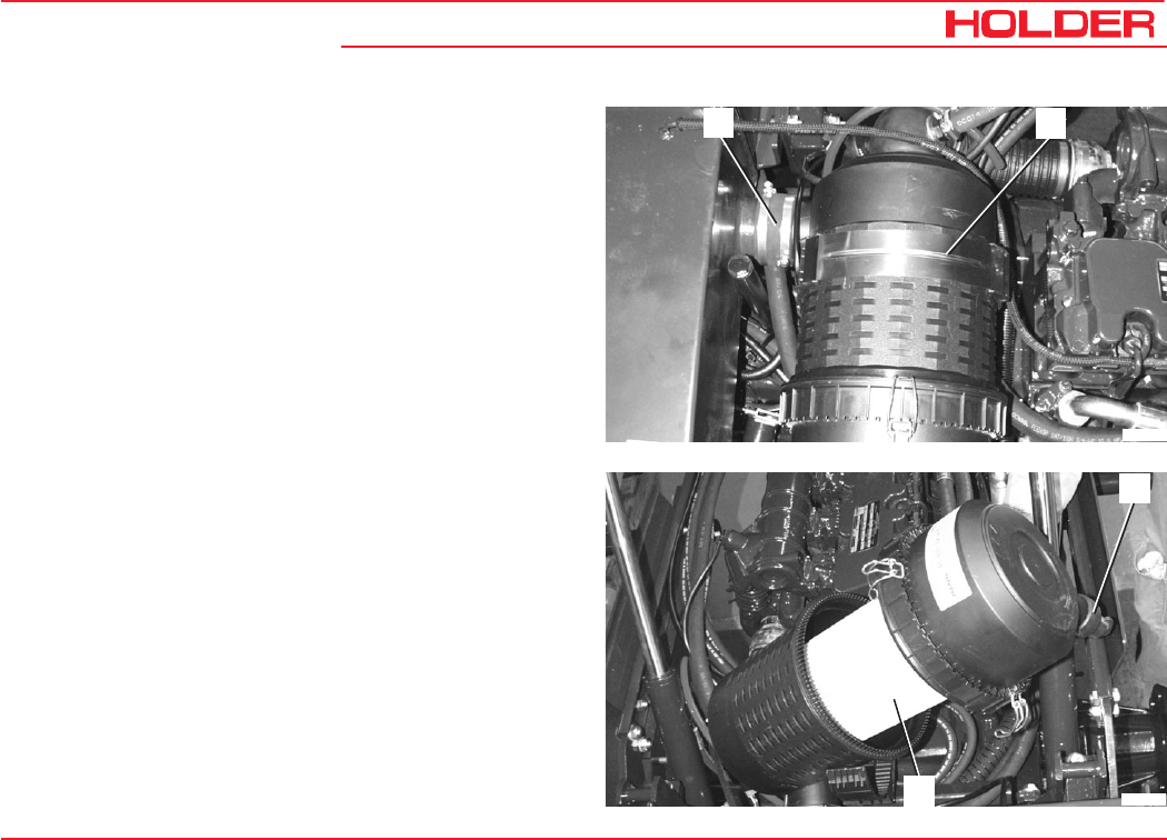
Operating Instructions
145 052 165
C 9700 ... C 9.88 H Maintenance as required
Checking the Air Cleaner System
The filter cartridge must be serviced when the flow resistance
of the filter is highest due to the restriction of the element.
This is indicated by the sounding of a horn.
-Stop the engine.
-Raise the dump body (loading platform*) and secure it
against accidental lowering.
-Loosen the hose clamp (1).
-Remove the air filter housing clamping band (2) and
turn the air filter housing up.
-Open the air filter cover clips.
-Pull of the housing cover and clean the dust ejection
valve (3).
-Pull the air filter cartridge (4) out of the housing by
rotating it slightly.
Cleaning:
- Blow out the air filter cartridge with compressed air
(max. 5 bar) from the inside out.
Replacement:
- Install a new air filter cartridge.
Clean the air filter housing with a moist cloth before
installation.
The installation of the air filter cartridge is in the reverse
order of removal.
Bild_148
12
Bild_149
4
3
* Option
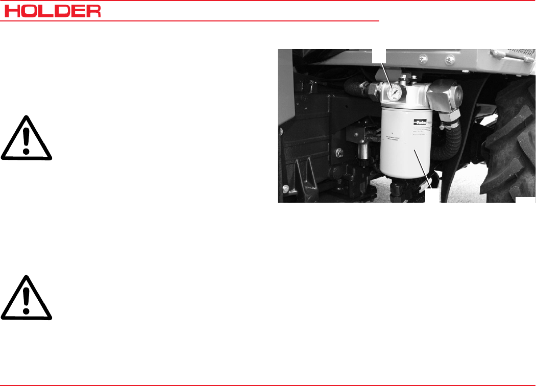
C 9700 ... C 9.88 H
Operating Instructions
166 145 052
Maintenance as required
Changing the Hydraulic Oil Return Filter for the
Variable Pump*
The hydraulic oil return filter with service indicator is located
at the rear right hand side of the tractor below the cabin.
ATTENTION
The hydraulic oil return filter must be replaced
if the pressure at the service indicator (1) rises
to 3 bar pressure when the engine is at idling
speed and the implement variable pump is
running when equipment (for example spiral-
bladed lawn mower) is installed.
- Relieve any pressure in the hydraulic system by
turning the implement off.
- Loosen the hydraulic oil return filter (2) with a filter
wrench.
ATTENTION
Observe the instructions for handling fuels
and lubricants.
- Clean the mating surface of the filter mount.
- Coat the new seal with oil.
* Option
Bild_150
2
1
- Install and hand tighten the new oil filter cartridge with
a new seal in the filter mount.
- Make a trial run and check for leaks.
- Check the hydraulic oil level.
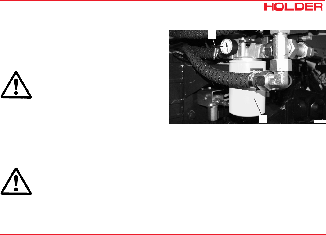
Operating Instructions
145 052 167
C 9700 ... C 9.88 H Maintenance as required
Changing the Hydraulic Oil Return Filter for Power
Hydraulics*
The hydraulic oil return filter with service indicator is located
at the rear right hand side of the tractor below the cabin.
ATTENTION
The hydraulic oil return filter must be replaced
if the pressure at the service indicator (1) rises
to 3 bar with the installed equipment (eg spi-
ral-bladed lawn mower) at engine idling speed
and the power hydraulics on.
- Relieve any pressure in the hydraulic system by
turning the implement off.
- Loosen the hydraulic oil return filter (2) with a filter
wrench.
ATTENTION
Observe the instructions for handling fuels
and lubricants.
- Clean the mating surface of the filter mount.
- Coat the new seal with oil.
- Install and hand tighten the new oil filter cartridge with
a new seal in the filter mount.
- Make a trial run and check for leaks.
- Check the hydraulic oil level.
* Option
Bild_151
2
1
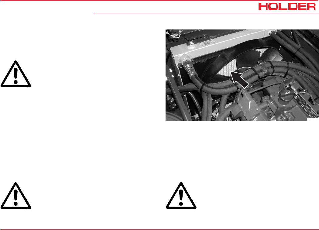
Operating Instructions
145 052 169
C 9700 ... C 9.88 H
Maintenance According to Intervals
Maintenance Every 125 Service Hours
ATTENTION
Carry out the services and inspections only
with the engine turned off.
Checking the Cooling System
- Inspect the cooling fins and oil cooler for the accumu-
lation of dirt.
Cleaning the Cooling System
Cleaning with Compressed Air
- Raise the dump body (loading platform*) and secure it
against accidental lowering.
-Blow compressed air through from the engine side to
remove any dirt and debris.
Cleaning with Cold Cleaner or Water Jet
ATTENTION
Maximum spray pressure 60 bar, maximum
steam temperature 60 °C
Bild_152
-Raise the dump body (loading platform*) and secure it
against accidental lowering.
-Spray the oil cooler and engine with a cold cleaner
and allow it to soak in for 10 minutes.
-Clean the oil cooler and engine with a strong water jet.
ATTENTION
Do not aim the water jet directly at delicate
parts such as the alternator; cover them if
necessary.
-Run the engine warm to prevent the formation of rust.
* Option
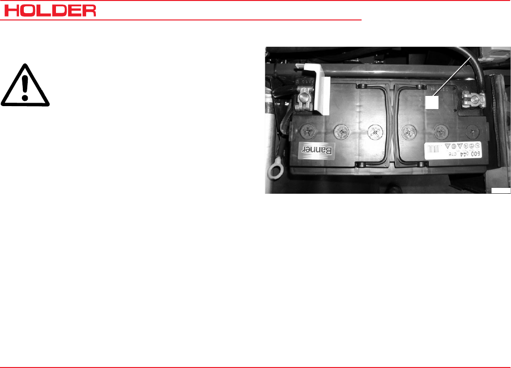
C 9700 ... C 9.88 H
Operating Instructions
170 145 052
Maintenance Every 125 Service Hours
Checking the Battery and Cable Connections
CAUTION
When working on the electrical equipment,
always disconnect the ground lead (1) of the
battery.
- Check the battery acid level and inspect the battery
for leaks. Observe the information of the battery
manufacturer.
- Remove any corrosion on the terminals.
- Grease the battery terminals with non-acidic battery
grease.
- Check cables and cable connections for secure
connection and damage.
- Replace any damaged cables and cable connections.
Checking the High Pressure Hoses
- Check the high-pressure hoses for cracks, bending
and chafing, and for porous surfaces.
Replace damaged high-pressure hoses immediately.
This work may only be carried out by an authorized workshop.
Bild_153
1
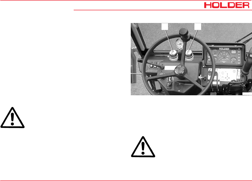
Operating Instructions
145 052 171
C 9700 ... C 9.88 H Maintenance Every 125 Service Hours
Checking the Steering Cylinders and Orbitrol
- Check the steering cylinders and orbitrol for damage
and leaks.
- Have damaged or leaky parts replaced by an authori-
zed workshop.
Checking the Brake Fluid Level for the Foot Brake
- Check the brake fluid level in the reservoir for the foot
brake (2). The brake fluid level should be between the
markings.
- To fill brake fluid, unscrew the reservoir cap (2) and
fill recommended brake fluid as far as the marking.
Filling quantity ......... approx. 0.4 litres (0.105 USGAL.)
ATTENTION
Do not mix different kinds of brake fluids.
Checking the Clutch* Brake Fluid Level
- Check the brake fluid level in reservoir for the clutch
(1). The brake fluid level should be between the
markings.
Bild_155
12
- To fill brake fluid, unscrew the reservoir cap (1) and
fill recommended brake fluid as far as the marking.
Filling quantity ........ approx. 0.25 litres (0.066USGAL.)
ATTENTION
Do not mix different kinds of brake fluids.
* mechanical gearbox only
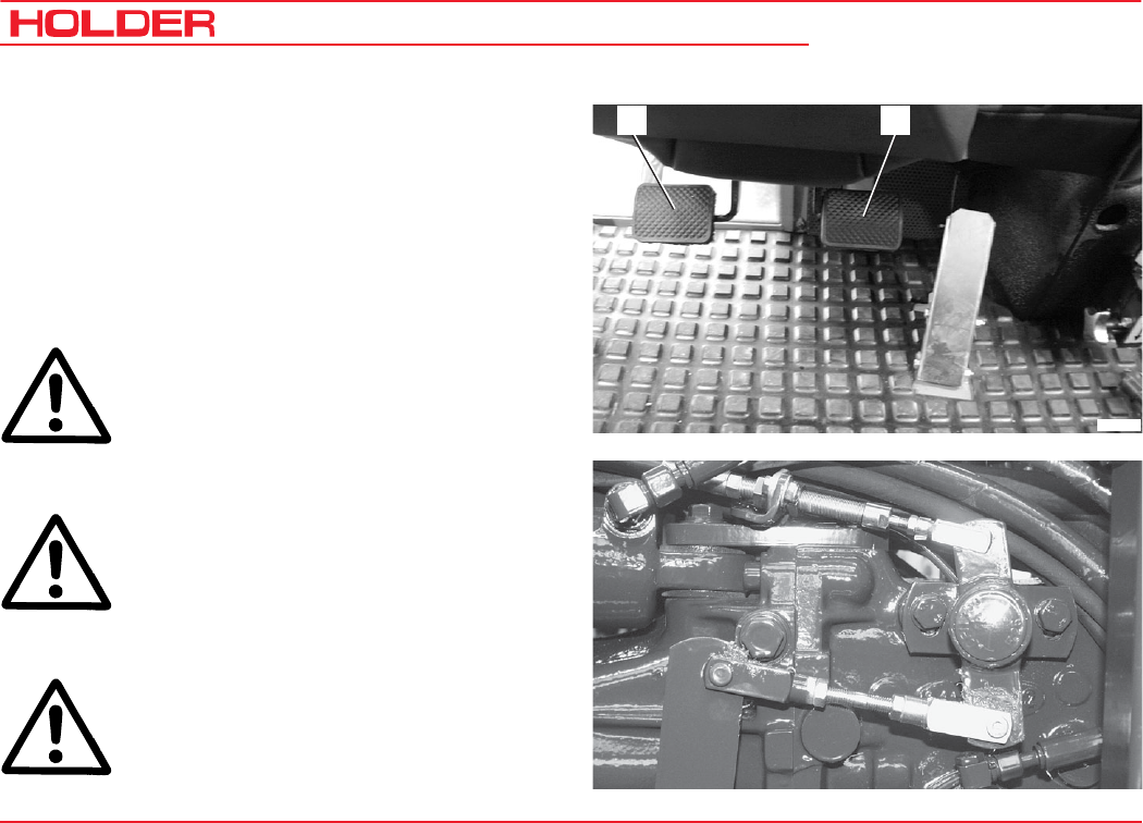
C 9700 ... C 9.88 H
Operating Instructions
172 145 052
Maintenance Every 125 Service Hours
Checking the Clutch (if mechanical gearbox is fitted)
- Have the clutch pedal play (1) checked by an authori-
zed workshop.
Checking the PTO clutch
Have this work carried out by an authorized workshop.
- Check the linkage rod for slight play. The clevises
should not be too tight or have too much play.
Checking the Braking System
DANGER
Do not operate the tractor with a defective
braking system.
-Carefully apply the parking brake while driving. The
tractor should be braked noticeably.
CAUTION
When the foot brake pedal (2) is depressed,
the tractor is braked strongly.
-Depress the foot brake pedal (2) while driving slowly.
The tractor should brake strongly.
DANGER
In case of irregularities with the braking
system, stop the tractor immediately and
have it checked by an authorized workshop.
12
Bild_167
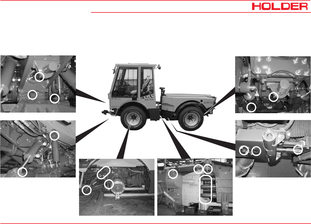
Operating Instructions
145 052 173
C 9700 ... C 9.88 H Maintenance Every 125 Service Hours
Bild_173
Tractor Lubrication
- Lubricate the grease nipples according to the lubrication chart. Only use recommended grease.
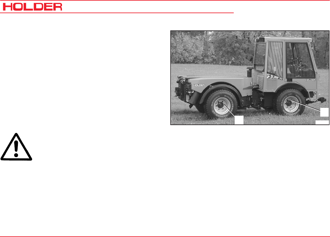
C 9700 ... C 9.88 H
Operating Instructions
174 145 052
Maintenance Every 125 Service Hours
Tightening Nuts and Bolts
- Tighten the transmission, axles and engine fasteners.
- Tighten fasteners to the specified torque according to
tables in the maintenance data.
Tightening the Wheel Nuts
- Tighten all wheel nuts at the front and rear wheels (1
and 2).
Torque ................................................................ 340 Nm
Checking the Electrical System
CAUTION
When working on the electrical system,
always disconnect the ground lead of the
battery!
- Raise the dump body (loading platform*) and secure
against accidental lowering.
- Check cables, plugs and cable ducts for damage and
security.
- Have any damaged parts replaced by an authorized
workshop.
Bild_171
1
2
* Option
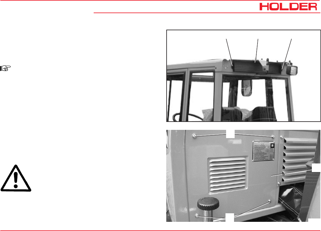
Operating Instructions
145 052 175
C 9700 ... C 9.88 H Maintenance Every 125 Service Hours
Bild_157
1 12
Cleaning the Upper Fresh Air Filter
- Remove the fastening screws (1).
- Remove the filter cover (2) and filter element.
- Clean the filter element or replace it.
NOTE
A charcoal filter* is available for such
applications as spraying insecticides, etc.
- Refit the filter cover and filter element.
Cleaning the Lower Fresh Air Filter
- Remove the fastening screws (3).
- Remove the rear panel (4) and take out the filter
element upwards.
- Clean the filter element or replace it.
- Re-install the filter element and rear panel.
ATTENTION
When a charcoal filter (in item 2) is installed,
the lower fresh air filter must be closed
airtight.
* Option
Bild_187
3
3
4
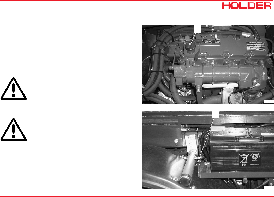
Operating Instructions
145 052 177
C 9700 ... C 9.88 H
Maintenance Every 500 Service Hours
Changing the Engine Oil
- Run the engine warm to operating temperature.
- Set the heating control to high.
- Place the tractor on level ground and turn off the
engine.
- Place a suitable oil pan underneath the engine.
CAUTION
Danger of scalding when draining hot engine
oil.
- Unscrew the oil drain plug.
- Allow the oil to run out completely.
ATTENTION
Observe the instructions for handling fuels
and lubricants.
- Screw the oil drain plug in again with a new seal and
tighten to a torque of 55 Nm.
- Fill new engine oil at the filler neck (1). Only use
recommended engine oil.
Filling quantity ....................... 8.75 litres (2.31 USGAL.)
- Let the engine idle shortly.
- After approx. 1 minute, check the oil level with the
dipstick (2).
Bild_189
1
2
Bild_18
8
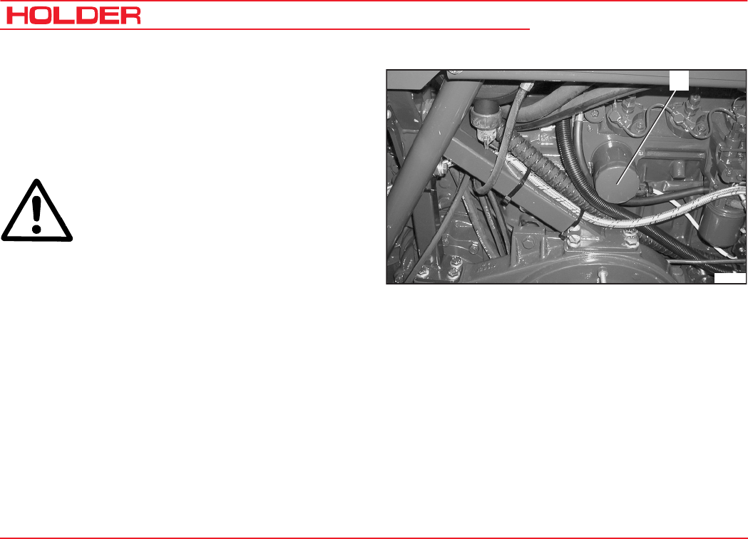
C 9700 ... C 9.88 H
Operating Instructions
178 145 052
Maintenance Every 500 Service Hours
Changing the Engine Oil Filter
See the operating manual of the engine manufacturer.
- Drain the engine oil.
- Unscrew the air filter cartridge (1) with a filter wrench.
ATTENTION
Observe the instructions on handling fuels
and lubricants.
- Clean the mating surface of the filter mount.
- Screw a new air filter cartridge with a new seal in the
filter mount until the seal makes contact.
- Tighten the air filter cartridge half a turn.
- Top up engine oil. Check the oil level.
Checking Hose Couplings for Leaks
- Check all hose couplings for leaks; use leakage
spray, if necessary. Eliminate any leaks immediately.
Bild_172
1
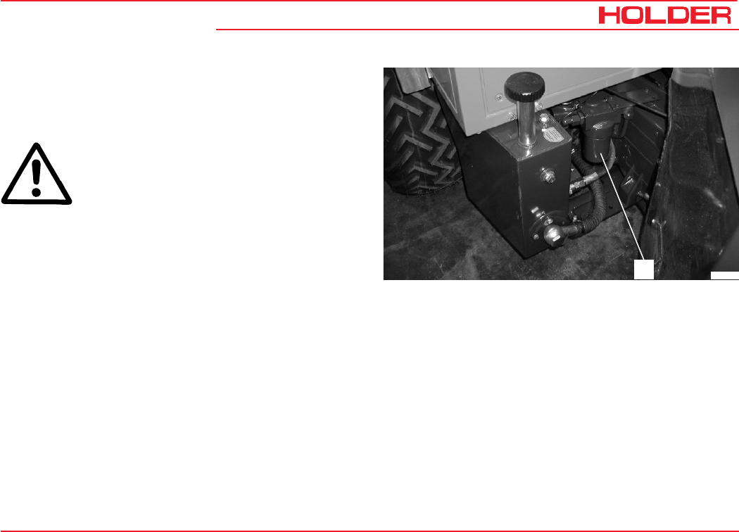
Operating Instructions
145 052 179
C 9700 ... C 9.88 H Maintenance Every 500 Service Hours
Changing the Hydraulic Oil Pressure Filter (Drive
Hydraulics)
- Remove the air filter housing (1) with a 24mm wrench.
ATTENTION
Observe the instructions on handling fuels
and lubricants.
- Clean the mating surface of the filter mount.
- Withdraw the pressure filter from the housing.
- Clean the housing.
- Coat the new seal with oil.
- Insert the new pressure filter in the air filter housing.
- Screw the air filter housing with a new seal in the filter
mount.
- Make a trial run and check for leaks.
- Check the hydraulic oil level.
Bild_159
1
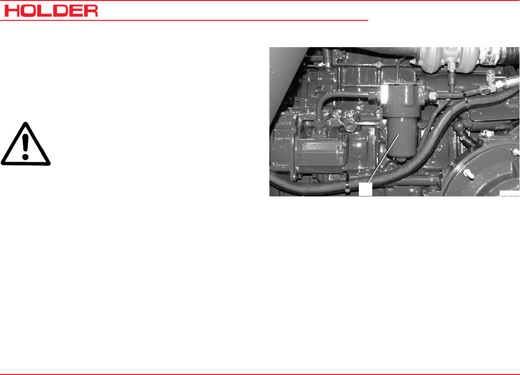
C 9700 ... C 9.88 H
Operating Instructions
180 145 052
Maintenance Every 500 Service Hours
Changing the Hydraulic Oil Pressure Filter (Imple-
ment Hydraulics)
- Relieve any pressure in the hydraulic system by
operating the control levers.
- Remove the air filter housing (1) with a 24mm wrench.
ATTENTION
Observe the instructions for handling fuels
and lubricants.
- Clean the mating surface of the filter mount.
- Withdraw the pressure filter from the housing.
- Clean the housing.
- Coat the new seal with oil.
- Insert the new pressure filter in the air filter housing.
- Screw the air filter housing with a new seal in the filter
mount.
- Make a trial run and check for leaks.
- Check the hydraulic oil level.
Bild_137
1
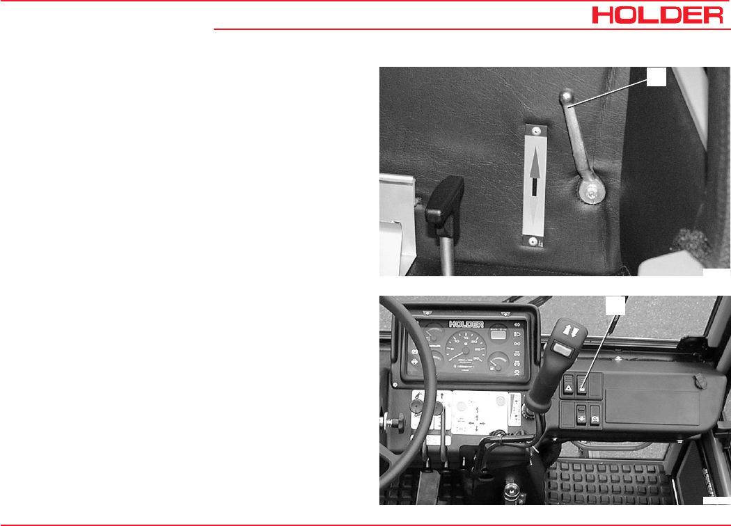
Operating Instructions
145 052 181
C 9700 ... C 9.88 H Maintenance Every 500 Service Hours
Checking the Heating System
- Set the heat shut-off valve lever (1) down to the
"OFF" position.
- Run the engine warm.
- Set the heat shut-off valve lever (1) up to the "ON"
position.
- Set the heating blower switch (2) to stage 2. Warm air
should flow out of the legroom heating nozzles.
2
Bild_045
1
Bild_160
Operating Instructions
145 052 183
C 9700 ... C 9.88 H
Maintenance Every 1000 Service
Hours
Checking Valve Clearance
See the operating manual of the engine manufacturer.
Checking the Battery
CAUTION
For the sake of your safety, observe the fol-
lowing instructions.
The battery contains dissolved sulphuric acid,
which is poisonous and caustic.
When working with battery acid, wear per-
sonal protective equipment (protective apron,
protective gloves) and eye protectors. If your
clothing, skin or eyes have nevertheless
come in contact with battery acid, the affected
parts must be rinsed at once with water. If
the eyes are affected, seek medical aid im-
mediately. Neutralize spilled battery acid im-
mediately.
Gases are released when batteries are
charged. To prevent an explosion, keep
sparks, naked fires away. Rooms, in which
batteries are charged or stored, must be
ventilated accordingly.
NOTE
The charging, servicing and care of the battery
must always be according to the maintenance
instructions of the battery manufacturer.
C 9700 ... C 9.88 H
Operating Instructions
184 145 052
Maintenance Every 1000 Service Hours
Changing the Fuel Filter
See the operating manual of the engine manufacturer.
- Remove the fuel filter cartridge with a filter wrench.
ATTENTION
Observe the instructions for handling fuels
and lubricants.
- Clean the mating surface of the filter mount.
- Coat the new seal with oil.
- Install and hand tighten the new filter cartridge with a
new seal in the filter mount.
NOTE
The fuel system bleeding takes place auto-
matically.
Cleaning/Replacing the Fuel Pump Strainer
See the operating manual of the engine manufacturer.
Checking V-belt Tension and Condition
See the operating manual of the engine manufacturer.
CAUTION
Adjust V-belt tension only when the engine is
shut off.
- Inspect V-belts for cracks and tears over their entire
length.
- Replace damaged V-belts.
- Using thumb pressure, check if the V-belt can not be
depressed more than 10 - 15 mm.
- To tighten the V-belt: Loosen the idler pulley mounting
screws and push the pulley outwards until the proper
V-belt tension is reached.
- Tighten the idler pulley mounting fastening screws.
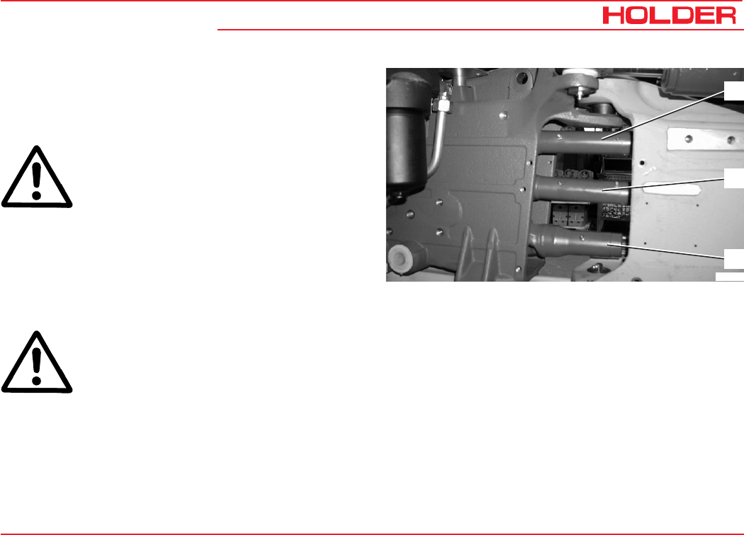
Operating Instructions
145 052 185
C 9700 ... C 9.88 H Maintenance Every 1000 Service Hours
Lubricating the Cardan Shaft
- Turn the steering wheel right or left until the steering
stop is met.
CAUTION
Carry out services in the articulated joint area
only with the engine shut off.
- Remove the rubber protector.
- Adjust the top cardan shaft (1) by hand until the grease
nipples are easily accessible.
- Grease the top cardan shaft.
- Move centre cardan shaft (2) with starter, until grease
nipples are easily accessible.
CAUTION
Make sure no-one is standing in the area of
the articulated joint when the starter is
operated.
- Grease the centre cardan shaft.
- Adjust the lower cardan shaft (3) by moving the tractor
forward or back until grease the nipples are easily
accessible.
- Grease the lower cardan shaft.
- Refit the rubber protector at the articulated joint.
Bild_168
1
2
3
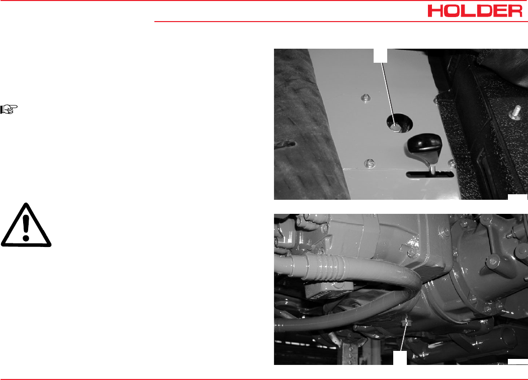
Operating Instructions
145 052 187
C 9700 ... C 9.88 H
Maintenance Every 1500 Service
Hours
Change the Front Gearbox Oil (Including Axles)
NOTE
Change the gear oil while still warm.
-Place the tractor on level ground.
-Unscrew the filler plug (1) at the front gearbox and
clean it with Diesel fuel.
-Place a suitable catch pan beneath the gearbox.
CAUTION
Danger of scalding when draining of hot gear
oil.
-Unscrew the oil drain plug (2) at the front gearbox and
wash it with Diesel fuel.
- Allow the oil to drain completely.
-Refit the oil drain plug with a new seal, ensuring it is
properly seated.
Bild_132
1
Bild_169
2
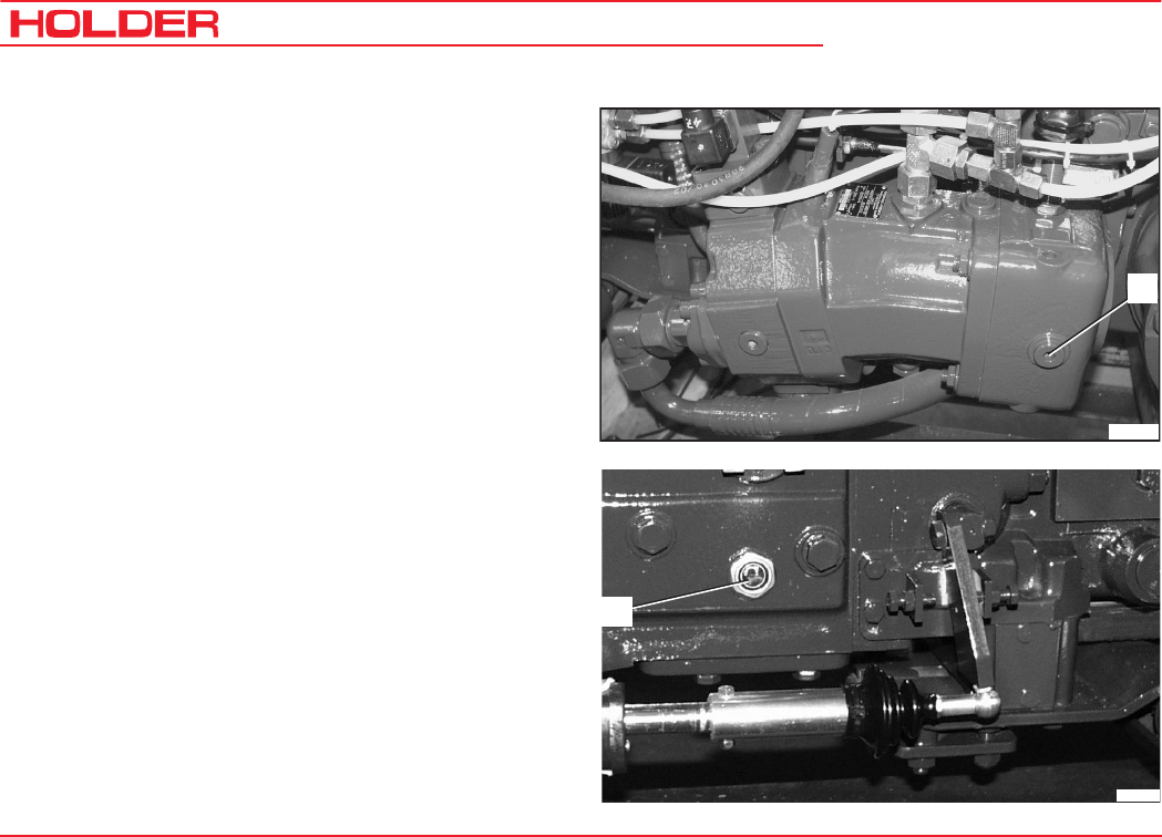
C 9700 ... C 9.88 H
Operating Instructions
188 145 052
Maintenance Every 1500 Service Hours
Filling Oil (Hydrostatic Drive Only)
- Unscrew the oil level plug (3).
- Fill recommended gear oil through the filler plug hole
until it runs out at the level plug hole.
Filling quantity ......... approx. 10.9 litres (2.88 USGAL.)
- Refit the oil level plug with a new seal, ensuring it is
properly seated.
3
Bild_174
Bild_175
4
Filling Oil (Gearbox Only)
- Fill recommended gear oil through the filler plug hole.
Filling quantity ......... approx. 10.9 litres (2.88 USGAL.)
- Check the oil level at the sight glass (4).
The oil level should be visible through the sight glass.
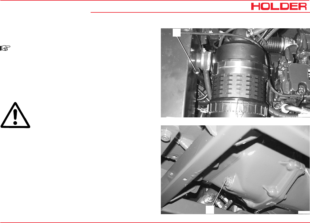
Operating Instructions
145 052 189
C 9700 ... C 9.88 H Maintenance Every 1500 Service Hours
Changing the Rear Gearbox Oil (Including Offset
Axles)
NOTE
Change the gear oil only when still warm.
-Place the tractor on level ground.
-Unscrew the filler plug (1) at the rear gearbox and
wash it with Diesel fuel.
-Place a suitable catch pan beneath the gearbox.
CAUTION
Danger of scalding when draining hot gear
oil.
-Unscrew the oil drain plug (2) at the rear gearbox and
wash it with Diesel fuel.
- Allow the oil to drain completely.
Bild_163
1
2Bild_19
0
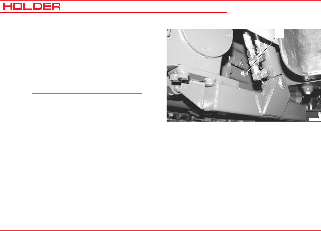
C 9700 ... C 9.88 H
Operating Instructions
190 145 052
Maintenance Every 1500 Service Hours
-Refit the oil drain plug with a new seal, ensuring it is
properly seated.
-Fill recommended gear oil through the filler plug hole.
Filling quantity ....... approx. 17.75 litres (4.69 USGAL.)
-Check the oil level at the sight glass (3).
- The oil level should be visible through the sight glass.
- Then fill another 3 litres (0.79 USGAL.) of gear oil.
Bild_191
1
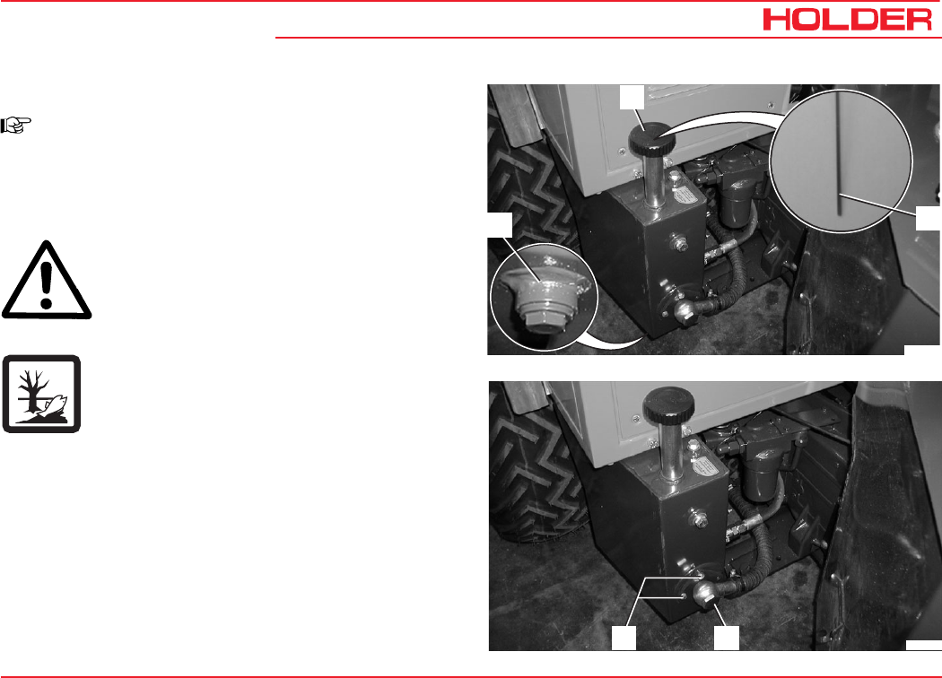
Operating Instructions
145 052 191
C 9700 ... C 9.88 H Maintenance Every 1500 Service Hours
Changing the Drive Hydraulics Oil
NOTE
Change the hydraulic oil while still warm.
-Place the tractor on level ground.
-Place a suitable oil container beneath the hydraulic oil
tank.
CAUTION
Danger of scalding when draining hot hydraulic
oil.
-Unscrew the oil drain plug (3).
Drain the oil.
-If required, flush the hydraulic oil tank with clean
hydraulic oil.
Checking or Cleaning the Hydraulic Oil Suction Filter
of Drive Hydraulics
- Unscrew the banjo screw (4) and move the hose to
the side.
-Remove the filter cover fastening screws (5).
-Withdraw the filter housing with the sieve-star filter.
Bild_138
2
1
3
Bild_143
4
5
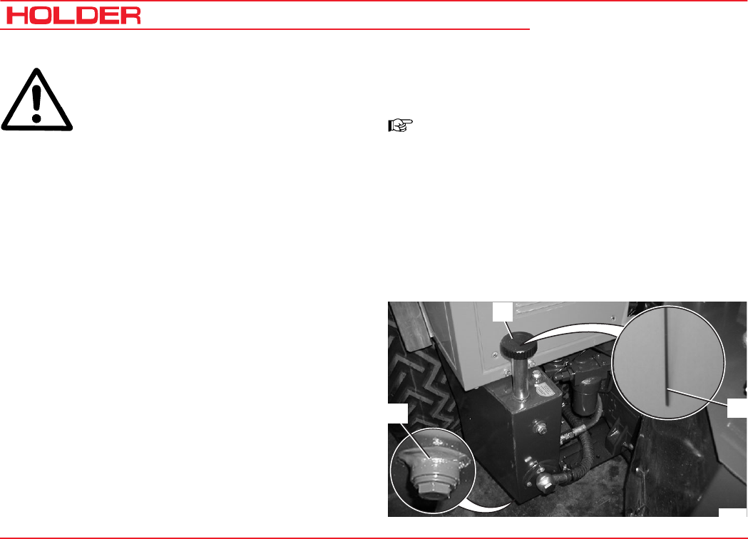
C 9700 ... C 9.88 H
Operating Instructions
192 145 052
Maintenance Every 1500 Service Hours
ATTENTION
Observe the instructions for handling fuels
and lubricants.
Cleaning:
- Wash the sieve-star filter with clean Diesel fuel.
Replacement:
- Unscrew the sieve-star filter from the filter housing
with a 24mm open-ended wrench.
-Fit a new toroidal sealing ring on the new filter and
screw it on to the filter housing.
The installation of the suction filter is carried out in the reverse
order of removal.
-Refit the oil drain plug (3) with new sealing ring,
ensuring it is properly seated.
-Fill recommended hydraulic oil through the filler neck
(1).
Filling quantity ............ approx. 19 litres (5.02 USGAL.)
-Check the oil level with the oil dipstick (2).
-Refit the filler neck cap.
-Start the engine and make a slow trial drive with the
tractor.
NOTE
The air in the hydraulic system is bled
automatically.
- Shut off the engine.
- Check for leaks.
- Recheck the oil level with the oil dipstick (2) and top
up hydraulic oil, if necessary .
Bild_138
2
1
3
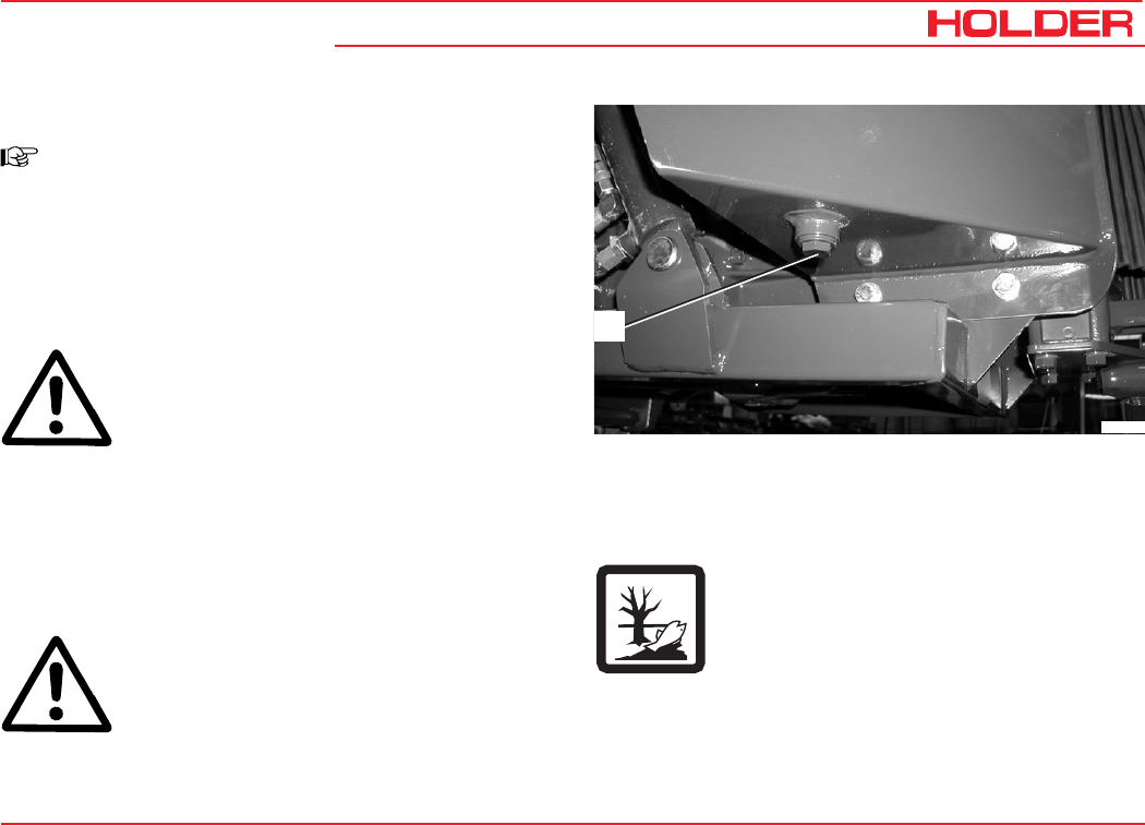
Operating Instructions
145 052 193
C 9700 ... C 9.88 H Maintenance Every 1500 Service Hours
Changing the Implement Hydraulics Oil
NOTE
Change the hydraulic oil while still warm.
-Place the tractor on level ground. Raise the loading
platform.
CAUTION
Secure the dump body (loading platform)*
against accidental lowering.
-Place a suitable oil container beneath the hydraulic oil
tank.
-Relieve any pressure in the hydraulic system by
operating the control levers.
CAUTION
Danger of scalding when draining hot hydraulic
oil.
Bild_139
1
-Unscrew the oil drain plug (1).
- Drain the oil.
Please ensure the oil is disposed of
properly.
-If required, flush the hydraulic oil tank with clean
hydraulic oil.
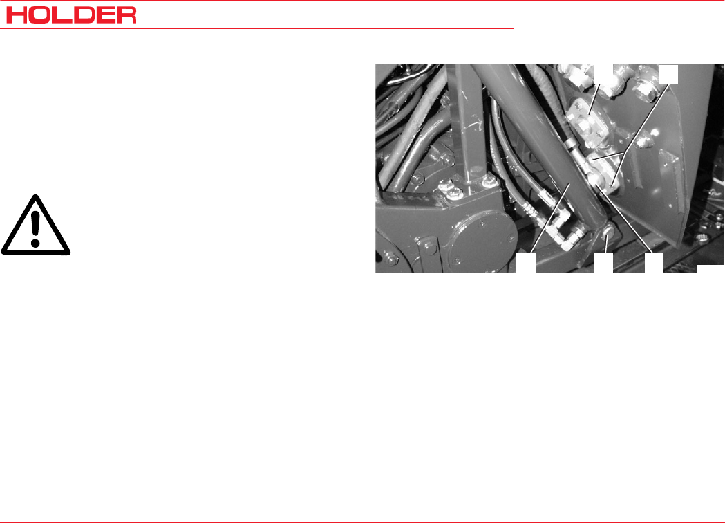
C 9700 ... C 9.88 H
Operating Instructions
194 145 052
Maintenance Every 1500 Service Hours
Checking or Cleaning the Implement Hydraulics
Suction Filter
-Remove the mounting pin (4) of the hydraulic cylinder
(5).
-Remove the banjo screw (3).
-Remove the filter cover fastening screws (2).
-Withdraw the filter housing with the sieve-star filter.
ATTENTION
Observe the instructions for handling fuels
and lubricants.
Cleaning:
- Wash the sieve-star filter with clean Diesel fuel.
Replacement:
- Unscrew the sieve-star filter from the filter housing
with a 24mm open-ended wrench.
-Screw the new filter with a new toroidal sealing ring on
to an the filter housing.
The installation of the suction filter is carried out in the reverse
order of removal.
If an implement variable pump* or power hydraulic system*
is installed, an additional sieve-star filter is installed in the
flange (1). If so, it must also be cleaned or changed as
described above.
Bild_142
543
2
1
* Option
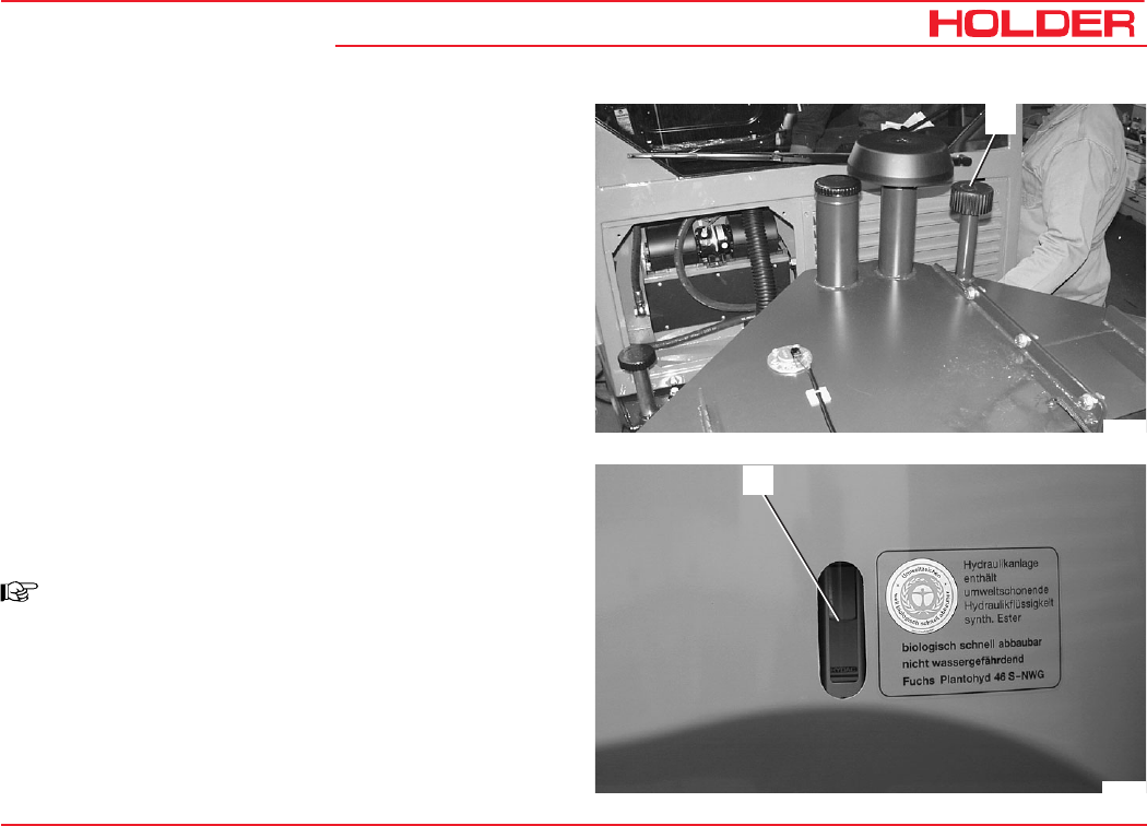
Operating Instructions
145 052 195
C 9700 ... C 9.88 H Maintenance Every 1500 Service Hours
7
Bild_166
- Refit the oil drain plug with a new seal, ensuring it is
properly seated.
- Fill recommended hydraulic oil through the filler neck
(6).
Filling quantity .......... approx. 45 litres (11.89 USGAL.)
6
Bild_140
- Check the oil level at the sight glass (7).
- Refit the filler neck cap.
- Start the engine. Operate the implement hydraulics and
steering.
NOTE
The air in the hydraulic system is bled
automatically.
- Shut off the engine and relieve any pressure in the
hydraulic system.
- Check for leaks.
- Check the oil level at the sight glass (7), adding
hydraulic oil if required.

C 9700 ... C 9.88 H
Operating Instructions
196 145 052
Maintenance Every 1500 Service Hours
Changing the Hydraulic Oil Return Filter for the
Implement Variable Pump*
Carry out the services and inspections as described in the
section "Maintenance as Required".
Changing the Hydraulic Oil Return Filter for Power
Hydraulics*
Carry out the services and inspections as described in the
section "Maintenance as Required".
* Option

Operating Instructions
145 052 197
C 9700 ... C 9.88 H
Maintenance Every 3000 Service Hours
Checking the Injection Nozzles
ATTENTION
This work may only be carried out by an
authorized workshop.
- Clean the fuel injector nozzles.
- Check the fuel injector nozzles with a test pressure of
210 +8 bar.
Changing the Toothed Belt
See the workshop manual of the engine manufacturer.
ATTENTION
This work may only be carried out by an
authorized workshop.
- Remove the left-hand cover of the toothed belt drive.
- Check the toothed belt for cracks over its entire
length.
- Replace damaged toothed belts.
NOTE
When replacing the toothed belt, also replace
the idler pulley.

Operating Instructions
145 052 199
C 9700 ... C 9.88 H Laying Up
Maintenance Every 2 Years
Changing the Implement Hydraulics Oil
See "Maintenance Every 1500 Service Hours".
The hydraulic oil must be changed at least every 2 years,
even if 1500 service hours were not reached.
Annual Maintenance
Examination of Implement Hydraulics Oil Samples
ATTENTION
This work may only be carried out by an
authorized workshop.
- Drain a small quantity of hydraulic oil from the hydrau-
lic oil tank for the implement hydraulics.
- Have the oil tested by an authorized workshop/test
lab for wear, abrasion chips and contamination.
- If the oil is contaminated, it must be changed. If not,
the oil can be used until the maximum of 1500 service
hours is reached or for another year, whichever
comes first.

Operating Instructions
145 052 201
C 9700 ... C 9.88 H
Laying Up
If the tractor is not going to be in service for over 2 months,
for example for operational reasons, it must be placed in a
well-ventilated, clean and dry room and the following
measures must be carried out.
- Clean the tractor thoroughly.
- Check the hydraulic oil levels, topping up oil if neces-
sary
- Cover all blank mechanical components with a thin
film of oil or grease.
- Grease the tractor.
- Check the condition and acid density of the battery;
cover the battery terminals with non-acidic grease.
(Observe the instructions of the battery manufactur-
er.)
- Remove the battery and store in a frost-free, dry
room.
Engine Preservation
- Clean the engine.
- Run the engine warm.
- Drain the engine oil and refill with anti-corrosion oil.
- Drain some fuel and refill the fuel tank with a mix of
90 % Diesel fuel and 10 % anti-corrosion oil.
- Run the engine for 10 minutes.
- Switch off the engine.
- Turn the engine over a few times by hand.
- Block up the intake opening and exhaust outlet.
ATTENTION
The tractor must be blocked up so that all
the wheels are off the ground to prevent a
permanent deformation of the tires.
NOTE
Do not use plastic foil to cover the tractor as
this enhances the formation and collection
of condensate water.
Putting the Tractor Back in Service after a Lay-up
If the tractor was taken out or service for over six months,
it must be inspected carefully before being put back in
service. The inspection should, similar to the safety
inspection, also cover all safety points of the tractor.
- Clean the tractor thoroughly.
- Lubricate the tractor.
- Check the condition and acid density of the battery,
recharging it if necessary.

C 9700 ... C 9.88 H
Operating Instructions
202 145 052
Laying Up
Removing Engine Preservation
- Unblock the intake opening and exhaust outlet.
- Drain the anti-corrosion oil and rinse the oil sump with
engine oil.
ATTENTION
Observe the instructions for handling fuels
and lubricants.
See the section "Changing the Engine Oil" on how to proceed
further.
- Check the hydraulic oil for condensate water, chan-
ging the oil if necessary.
- Perform the services and inspections as for before
taking into service.
- Refill the fuel tank.
- Change the brake fluid.
- Take the tractor in operation.
When taking into the tractor into service, particularly check:
- Gearboxes and axles for leaks.
- Drive hydraulics, gearshift, steering.
- Brake (service brake, parking brake)
- Implement hydraulics, functions and work move-
ments.
If the tractor is to be laid up for a longer period, please
contact your HOLDER Service for further measures.

Operating Instructions
145 052 203
C 9700 ... C 9.88 H
Recommended Fuels and
Lubricants
Recommended Hydraulic and Gear Oils
Manufacturer Recommended Hydraulic Oil
HE Oils (Hydr. Ester)
Recommended Gear Oil for Gearbox
und Hydrostatic Transmission
Utto / Stou
ISO Viscosity Class
HLP (HM) HV
VG 46
AGIP Agip Arnica S 46 Agip Rotra JDF
ARAL Vitam EHF 46 Aral Fluid HGS 10W30
AVIA Syntofluid 46 -----
BECHEM Hydrostar HEP 46 -----
BP Biohyd SE 46 – S BP Hydraulic TF - JD
BAYWA Plantosyn 3268 ECO -----
BUCHER Motorex Biosynt 3268 Farmer 304 JD-M20C
DEA Econa E 46 -----
ESSO Univis HE – ES 46 Unifarm 15W - 40
ELF Hydrelf Bio 46 -----
Total Total Biohydran TMP Total Multiagri Super 10W-30
FUCHS Plantohyd 46 S-NWG -----
OEST Bio Synthetik HYD 46 -----
SHELL Naturelle HF – E 46 Shell Harvella T 10W-30
VALVOLINE Valvoline Ultraplant ------

C 9700 ... C 9.88 H
Operating Instructions
204 145 052
Recommended Fuels and Lubricants
Recommended Engine Oils and Lubricants
The following oil brands conform to US Military Specification
MIL-L-2104C or to API quality CD/SF and ACEA.
Manufacturer Recommended Lubricating
Oil
SAE
Class
Recommended Lubricant
Penetration Ratio
260 - 290
AGIP
AGIP
Agip Sigma Ultra TFE
Autol Valve Ultra FE
10W-40
10W-40
Agip GR MU 2
ARAL GmbH
ARAL GmbH
Aral Mega Turboral
Aral Super Turboral
10W-40
5W-30
Multi-purpose grease
Long-service grease H
BAYWA
BAYWA
BayWa Super Truck 1040 MC
BayWa Turbo 4000
10W-40
10W-40
Baywa multi-purpose grease 2
Special grease FLM
CASTROL GmbH
CASTROL GmbH
Castrol SYNTRUCK
Castrol DYNAMAX
5W-40
7,5W-40
Castrol LM
CHEVRON Chevron Delo 400 Synthic 5W-40
ESSO Essolube XTS 501 10W-40 Esso Beacon 2 multi-purpose grease
FINA
FINA
Fina Kappa First
Fina Kappa Ultra
5W-30
10W-40
Fina Marson L2
Fina Marson EPL 2
FUCHS DEA
FUCHS DEA
FUCHS DEA
FUCHS DEA
FUCHS DEA
FUCHS DEA
Dea Cronos Synth
Dea Cronos Premium LD
Fuchs Titan Cargo MC
Deutz Oil TLL 10W- 40MB
Dea Cronos Premium FX
Fuchs Titan Unic Plus MC
5W-40
10W-40
10W-40
10W-40
10W-40
10W-40
Glissando 20
Glissando 283 EP 2
Renolit LZR 2
Operating Instructions
145 052 205
C 9700 ... C 9.88 H
Recommended Fuels and Lubricants
Recommended Engine Oils and Lubricants continued
Brake Fluid
N-DOT 3, DOT 4
DANGER
Do not use mineral oil.
Fuels
Observe the specifications of the engine manufacturer.
NOTE
The use of bio diesel fuel is only allowed after
a conversion of the engine by an authorized
workshop.
Manufacturer Recommended Oil SAE
Class
Lubricants
Penetration Ratio
260 - 290
MOBIL OEL
MOBIL OEL
MOBIL OEL
Mobil Delvac 1 SHC
Mobil Delvac 1
Mobil Delvac XHP Extra
5W-40
5W-40
10W-40
Mobilgrease MB 2
BP OIL International BP Vanellus HT Extra 10W-40 BP Energrease LS 2
BP multi-purpose grease L2
Shell International Shell Myrina TX/
Shell Rimula Ultra
5W-40 Retinax EP2
Shell International Shell Myria TX/
Shell Rimula Ultra
10W-30
TOTAL Total Rubia TIR 8600 10W-40
Wintershall TFG 10W-40

C 9700 ... C 9.88 H
Operating Instructions
206 145 052
Maintenance data
Filling Quantities
operated with HE oil. Residual quantities of
mineral oils reduce the biological degrada-
bility. They do not influence operation.
C 9700
C 9.72
C 9700/9800 H
C 9.72/83 H
C 9.78/88 H
Engine oil
Including filter 0.5 litres (0.132 USGAL.)
Including heating system 1.5 litres (0.396 USGAL.)
12.5 litres (3.3 USGAL.) 12.5 litres (3.3 USGAL.)
Front gearbox with axles, gear oil 10.9 litres (2.88 USGAL.) ---
Front hydrostatic drive with axles, gear oil
Initial filling
---
---
10.9 litres (2.88 USGAL.)
12.7 litres (3.35 USGAL.)
Rear gearbox with axles, gear oil 17.75 litres (4.69 USGAL.) 17.75 litres (4.69 USGAL.)
Implement hydraulics, hydraulic oil* approx. 45 - 50 litres
(11.89 - 13.21 USGAL.)
approx. 45 - 50 litres
(11.89 - 13.21 USGAL.)
Hydraulic oil tank for drive, hydraulic oil*
Initial filling
---
---
19 litres (5.02 USGAL.)
22 litres (5.81 USGAL.)
Brake fluid for hydr. clutch 0.25 litres (0.066 USGAL.) ---
Brake fluid for hydr. foot brake 0.4 litres (0.105 USGAL.) 0.4 litres (0.105 USGAL.)
Fuel tank, Diesel fuel 86 litres (22.7 USGAL.) 86 litres (22.7 USGAL.)
* NOTE:
In order to ensure the biological degradability
of the hydraulic oil, all implements connected
to the tractor hydraulic system must also be

Operating Instructions
145 052 207
C 9700 ... C 9.88 H
Maintenance data
Tightening Torques
Hexagon Screws and Studs M 8 M 10 M 12 M 14 M 16
Screw quality 8.8 25 Nm 49 Nm 86 Nm 135 Nm 210 Nm
Screw quality 10.9 35 Nm 69 Nm 120 Nm 190 Nm 295 Nm
Gearbox, Axles, Wheels Tightening Torque
Hexagon screws M 10
(servostat to steering support) 40 Nm
Tension screws for hydraulic
control valves 25 Nm
Axle housing to gearbox 86 Nm
Axle housing cover M 10
(planetary gears) 69 Nm
Pendulum bearing M 12 86 Nm
Pendulum limit stop M 16 210 Nm
Hitch bar for hitch coupling
M 14 135 Nm
Wheel nuts (incl. wheel hub
spacers) 340 Nm
Engine Torque
Idler/drive belt 45 Nm
Cylinder head cover 9 + 1 Nm
Rocking lever adjustment
screw 20 + 2 Nm
Suction pipe (TORX) 21 Nm
Exhaust pipe (TORX) 40 Nm
Oil drain plug 55 + 5 Nm
Injection valve clamp (TORX) 21 Nm
Plugs and union nuts for
heating hoses 65 + 5 Nm

C 9700 ... C 9.88 H
Operating Instructions
208 145 052
Maintenance data
List of Replacement Parts
Description Order No.
Sealing ring for oil drain plug 010 395
Engine oil filter 797 135
Valve cover seal 787 357
Air filter cartridge 029 760
KHD fan V-belt 784 992
Fuel filter 782 971
Hydraulic suction filter (implement hydraulic system) 029 541
O-ring 64x3 014 696 (2 items)
Hydraulic suction filter (drive hydraulic system) 029 540
O-ring 64x3 014 696 (2 items)
Hydraulic pressure filter (implement and drive hydraulic system) 132 897 (1 item each)
O-ring for hydraulic pressure filter 028 109
Toothed belt repair kit 786 262
Replacement cartridge for service hydraulics return line filter 029 088
Replacement cartridge for implement variable pump return line filter 143 991

Operating Instructions
145 052 209
C 9700 ... C 9.88 H
Maintenance data
Bulbs 12 V
Lights Rating
Lights Rating
Headlights H4 60/55 W Hazard warning light switch 2 W
Turn signal light. front 21 W Engine temperature gauge light 1.2 W
Turn signal light. rear 21 W Fuel gauge light 1.2 W
Tail light 10 W Indicator lights 1.2 W
License plate light 5 W Clearance lights 5 W
Stop light 21 W Interior light 5 W
Back-up light 21 W Rotating beacon 45 W
Tachometer for engine and
PTO rpm
1.2 W Multi-function instrument light
DIN 72601/W5/12 V
1.2 / 2.0 / 3.0 W
Speed and PTO shaft indicator 1.2 W

C 9700 ... C 9.88 H
Operating Instructions
210 145 052
Maintenance data
Technical Data of Engine C 9700/9.72
C 9700/9.72H
C 9800/9.83H
Manufacturer Deutz AG Deutz AG
Type BF4M1011 53,5 KW BF4M1011F 61 KW
Design In-line vertical engine In-line vertical engine
Mode of operation 4-stroke Diesel 4-stroke Diesel
Cooling Oil cooling Oil cooling
Injection system Direct fuel injection Direct fuel injection
Number of cylinders 4 4
Cylinder bore Ø 91 Ø 91
Stroke 112 112
Cylinder capacity 2914 2914
Compression ratio 18 18
Compression pressure 22-27 bar 22-27 bar
Charging pressure 1.25bar 1.25bar
Valve tolerance (cold engine) Intake valve 0.3 mm
Exhaust valve 0.5 mm
Intake valve 0.3 mm
Exhaust valve 0.5 mm
Fuel consumption 223g/KW-h at 1500-1750 rpm 222g/KW-h at 1750-1850 rpm
Air filter Mann and Hummel dry air filter with
acoustic alert
Mann and Hummel dry air filter with acoustic
alert
Lubrication system Forced-feed lubrication Forced-feed lubrication
Lubrication oil consumption Maximum 0.5% of fuel consumption Maximum 0.5% of fuel consumption
Oil filter Changeable cartridge in main flow Changeable cartridge in main flow
Oil pressure at n=900 rpm 2,0 bar 2.0 bar
Rated speed 2500 rpm 2600 rpm
Maximum idling speed 2600 rpm 2750 rpm
Minimum idling speed 900 rpm 900 rpm
Maximum torque 235 Nm at 1750 - 1850 rpm 255 Nm at 1750 - 1850 rpm
Power acc. to ICE.24/89/
491/EWG at n=2800 rpm 53.5 KW (72 HP (DIN)) 61 KW (83 HP (DIN))

Operating Instructions
145 052 211
C 9700 ... C 9.88 H
Maintenance data
Engine Specifications C 9.78H C 9.88H
Manufacturer Deutz AG Deutz AG
Type BF4M2011 57 KW BF4M2011 65 KW
Design In-line vertical engine In-line vertical engine
Mode of operation 4-stroke Diesel 4-stroke Diesel
Cooling Oil cooling Oil cooling
Injection system Direct fuel injection Direct fuel injection
Number of cylinders 4 4
Cylinder bore Ø 94 Ø 94
Stroke 112 112
Cylinder capacity 3108 3108
Compression ratio 17.5 17.5
Compression pressure ------- --------
Charging pressure 0.9 bar 1.15 bar
Valve tolerance (cold engine) Intake valve 0.3 mm
Exhaust valve 0.5 mm
Intake valve 0.3 mm
Exhaust valve 0.5 mm
Fuel consumption 216 g/KW-h at 1750-1850 rpm 216 g/KW-h at 1550-1650 rpm
Air filter Mann and Hummel dry air filter with
acoustic alert
Mann and Hummel dry air filter with acoustic
alert
Lubrication system Forced-feed lubrication Forced-feed lubrication
Lubrication oil consumption Maximum 0.5% of fuel consumption Maximum 0.5% of fuel consumption
Oil filter Changeable cartridge in main flow Changeable cartridge in main flow
Oil pressure at n=900 rpm 2.0 – 2.5 bar 2.0 – 2.5 bar
Rated speed 2500 rpm 2800 rpm
Maximum idling speed 2750 rpm 3050 rpm
Minimum idling speed 900 rpm 900 rpm
Maximum torque 246 Nm at 1550 - 1650 rpm 266 Nm at 1550 - 1650 rpm
Power acc. to ICE.24/89/
491/EWG at n=2800 rpm 57 KW (78 HP (DIN)) 65 KW (88 HP (DIN))

C 9700 ... C 9.88 H
Operating Instructions
212 145 052
Maintenance data
Fuel System
all vehicles
Fuel injection pump BOSCH individual withdrawable element-
type calibrated pump
Governor Governor integrated in front cover
Injection nozzle 5-hole nozzle
Injection pressure 210 bar + 8 bar
Start of fuel injection 4°+/-1° BTDC for 1011
6°+/-1° BTDC for 2011
Drive pump Hydrostatic drive
Axial piston pump, Type 11 VG50 EP
Rated pressure 300 bar,
Maximum pressure 350 bar
A4 VG40 EP
Rated pressure 380 bar
Maximum pressure 430 bar
Drive motor Axial piston motor /Type AG KM 55

Operating Instructions
145 052 213
C 9700 ... C 9.88 H
Page Page
Alphabetical Index
A
Accessories ..................................................................48
Activating Functions (Operation) ................................. 102
Additional Information for Implements ...........................86
Adjusting Catch Hook and Catch Hook Bar ...................90
Adjusting the Backrest ..................................................55
Adjusting the Backrest Tilt ............................................ 57
Adjusting the Driver's Seat ............................................55
Adjusting the Driver's Weight .........................................56
Adjusting the Horizontal Suspension .............................56
Adjusting the Inch Knob ................................................69
Adjusting the Length of the Catch Hook Bar .................. 90
Adjusting the Lumbar Padding .......................................55
Adjusting the Passenger Seat ....................................... 57
Adjusting the Seat Horizontally .............................. 56, 57
Adjusting the Speedometer ................................ 141, 163
Adjusting the Steering Wheel ........................................54
Adjusting the Track Width ..............................................82
Adjusting the Upper Link Mount ....................................91
Adjusting the Weight .....................................................57
Air Conditioner ............................................................ 129
Air Conditioning ........................................................... 129
Annual Maintenance.................................................... 199
Approved Applications ................................................... 5
Attaching Implements ...................................................89
B
Ballast Weights .............................................................84
Battery ..........................................................................14
Battery Acid ..................................................................13
Bearing Load ............................................................... 136
Before Starting to Drive ................................................63
Brake Fluid ................................................................. 205
Braking .........................................................................77
Bulbs 12 V .................................................................. 209
C
Change the Front Gearbox Oil (Including Axles) .......... 187
Changing the Direction of Travel ............................. 70, 75
Changing the Drive Hydraulics Oil ............................... 191
Changing the Engine Oil .............................................. 177

C 9700 ... C 9.88 H
Operating Instructions
214 145 052
Index
Page Page
Changing the Engine Oil Filter ..................................... 178
Changing the Fuel Filter .............................................. 184
Changing the Hydraulic Oil Pressure Filter
(Drive Hydraulics) ................................................ 179
Changing the Hydraulic Oil Pressure Filter
(Implement Hydraulics) ........................................ 180
Changing the Hydraulic Oil Return Filter
for Power Hydraulics ................................... 167, 196
Changing the Hydraulic Oil Return Filter for the
Implement Variable Pump .................................... 196
Changing the Hydraulic Oil Return Filter for the
Variable Pump ..................................................... 166
Changing the Implement Hydraulics Oil .............. 193, 199
Changing the Rear Gearbox Oil
(Including Offset Axles) ....................................... 189
Changing the Toothed Belt ........................................... 197
Check the Engine for Leaks ........................................ 161
Checking Engine Oil Level ............................................50
Checking Hose Couplings for Leaks ............................ 178
Checking or Cleaning the Hydraulic Oil
Suction Filter of Drive Hydraulics ......................... 191
Checking or Cleaning the Implement Hydraulics
Suction Filter ....................................................... 194
Checking the Air Cleaner System ............................... 165
Checking the Battery .................................................. 183
Checking the Battery and Cable Connections ............. 170
Checking the Brake Fluid Level .....................................54
Checking the Brake Fluid Level for the Foot Brake ..... 171
Checking the Braking System ..................................... 172
Checking the Clutch
(if mechanical gearbox is fitted) ........................... 172
Checking the Clutch Brake Fluid Level ........................ 171
Checking the Cooling System ..................................... 169
Checking the Drive Hydraulics Oil Level........................ 52
Checking the Electrical System .................................. 174
Checking the Heating System ..................................... 181
Checking the High Pressure Hoses ............................. 170
Checking the Implement Hydraulics Oil Level ...............52
Checking the Injection Nozzles ................................... 197
Checking the Lights and Rear View Mirror .....................58
Checking the PTO clutch ............................................ 172
Checking the Steering Cylinders and Orbitrol .............. 171
Checking the Trailer Hitch (Optional), if required ............51
Checking Tire Inflation Pressure ....................................51

145 052 215
C 9700 ... C 9.88 H Index
Operating Instructions
Page Page
Checking V-belt Tension and Condition ........................ 184
Checking Valve Clearance ........................................... 183
Cleaning the Cooling System ...................................... 169
Cleaning the Lower Fresh Air Filter .............................. 175
Cleaning the Upper Fresh Air Filter .............................. 175
Cleaning with Cold Cleaner or Water Jet ...................... 169
Cleaning with Compressed Air..................................... 169
Cleaning/Replacing the Fuel Pump Strainer ................ 184
Connecting Equipment to Power Socket ...................... 126
Control Lever Functions ................................................95
Controls for Mechanical Gearbox ..................................40
Controls in Cabin at Rear ..............................................42
Controls on Cabin Console at Front Left ........................41
Controls on Cabin Console at Front Right ......................41
Coupling Hydraulic Lines ...............................................92
D
Date of Issue and Manual Version .................................. 2
Description ....................................................................28
Development .................................................................. 1
Disengaging the Differential Lock ..................................76
Disengaging the Parking Brake .....................................78
Drive Range Pre-selection Lever between Seats ...........37
Driver's license ............................................................... 7
Driver's license classes (Germany only)......................... 7
Driver's Station ..............................................................30
Driving ..........................................................................64
Driving on Slopes ..........................................................79
Driving Safety Rules .....................................................63
Driving with Hydrostatic Drive,
Digital Electronics and Dual Drive ..........................71
Driving with the Mechanical Gearbox ............................73
Driving with Trailers ..................................................... 137
E
Emissions .....................................................................13
Engaging the Differential Lock....................................... 76
Engaging the Front PTO .............................................. 104
Engaging the Parking Brake .......................................... 78
Engaging the Rear PTO .............................................. 105
Engine Oil for Winter Operation .....................................84
Engine Preservation .................................................... 201
Engine Specifications ........................................... 21, 211
Examination of Implement Hydraulics Oil Samples ..... 199

C 9700 ... C 9.88 H
Operating Instructions
216 145 052
Index
Page Page
Exhaust Gas Identification ............................................27
Exhaust Gases .............................................................13
Explanations of Terminology ........................................... 2
F
Filling Fuel ....................................................................53
Filling Oil (Gearbox Only) ............................................ 188
Filling Oil (Hydrostatic Drive Only) .............................. 188
Filling Quantities ......................................................... 206
Filling Washing Water ....................................................58
Foot Pedals ...................................................................36
Foreword ........................................................................ 1
Front Implement ............................................................87
Front Left View .............................................................. 28
Front Lift 1 - Lifting/Lowering .........................................99
Front Lift 2 - Shifting Left/Right ................................... 100
Front Lift 3 - Lateral Tilt ............................................... 101
Front PTO Selector .......................................................38
Front Windshield Wiper/Washer ................................... 120
Fuel System ............................................................... 212
Fuels ........................................................................... 205
Functions of Lock-out Knob ..........................................95
Fuse for Air Conditioning ............................................. 131
Fuses ......................................................................... 130
Fuses for the Cabin ..................................................... 131
Fuses for the Tractor ................................................... 130
G
Gear Oil, Engine Oil, Diesel Fuel...................................12
General Notes on Safety ...............................................11
General Notes on Service .............................................. 1
General Remarks on Maintenance .............................. 149
H
Handling fuels and lubricants ...................................... 151
Heat ..............................................................................14
Heater ...........................................................................38
Heater and ventilation ................................................. 127
Heating ....................................................................... 127
How to Value the Tractor? ............................................ 149
Hydraulic Carrier Control (Power Lifter) .......................... 36
Hydraulic Oil, Brake Fluid .............................................13
Hydraulic Oil Flow for Stationary Operation ...................81
Hydraulic System..........................................................84

145 052 217
C 9700 ... C 9.88 H Index
Operating Instructions
Page Page
I
Identification Plates ...................................................... 43
Implement and Engine Controls (Details) ......................32
Indicators, Adjustments .............................................. 141
Installing the Cardan Shafts ..........................................93
Instructions before Starting ...........................................59
Instructions before Starting the Engine .........................59
Instructions for Loading ............................................... 139
Instructions for Operation ............................................... 7
Instructions for the Tractor .............................................. 5
Instructions for Towing ................................................. 140
Instructions for Transport ............................................. 139
Interior Light ................................................................ 125
J
Jack Lifting Points ...................................................... 154
Jacking Up .................................................................. 154
L
Laying Up .................................................................... 201
Leaving the Tractor ............................................. 133, 134
Legend for Multi-function Display ..................................39
Lights .......................................................................... 121
List of Replacement Parts ........................................... 208
Location of Plates and Labels .......................................43
Lubricating the Cardan Shaft ....................................... 185
M
Maintenance According to Intervals ............................ 169
Maintenance after the First 50 Operating Hours .......... 161
Maintenance as Required ............................................ 163
Maintenance during the
First Period of Operation ............................. 157, 161
Maintenance Every 1000 Service Hours ...................... 183
Maintenance Every 125 Service Hours ....................... 169
Maintenance Every 1500 Service Hours ...................... 187
Maintenance Every 2 Years ......................................... 199
Maintenance Every 3000 Service Hours ...................... 197
Maintenance Every 500 Service Hours ....................... 177
Maintenance Schedule ................................................ 157
Model Variants ..............................................................15
Mounting Instructions for License Plate ........................44
Multi-function Lever ....................................................... 33
Multi-function Lever (Variant 1) ............................... 33, 96
Multi-function Lever (Variant 2) ............................... 34, 98

C 9700 ... C 9.88 H
Operating Instructions
218 145 052
Index
Page Page
Multi-function Lever (Variant 3) ......................................35
Multi-function Lever (Variant 4) .................................... 102
Multi-function Lever (Variant 4) ......................................35
Multi-function Lever Functions ......................................96
N
Noise Level ...................................................................27
Note on Disposal of Tractor ............................................ 6
O
Opening the roof hatch ................................................ 119
Operating controls .........................................................30
Operating Controls Behind the Seat ..............................37
Operating Implements ...................................................94
Operating priority flow valve II ..................................... 117
Operating the Air Conditioner ...................................... 129
Operating the Driver's Cab .......................................... 119
Operating the Horn ...................................................... 123
Operating the Hydraulic Carrier (Power Lifter) .............. 106
Operating the Hydraulic Control Levers .........................94
Operating the Hydraulic Dumper .................................. 112
Operating the Implements .............................................85
Operating the Inch Pedal ...............................................70
Operating the Power Hydraulics ( 75 L Fixed Flow) ..... 110
Operating the Priority Flow Valve I .............................. 115
Operating the PTO ...................................................... 103
Operating the Radio .................................................... 126
Operating the roof hatch .............................................. 119
Operating the Service Brake .........................................77
Operating the Trailer Coupling, Attaching Trailers ......... 136
Operation ......................................................................63
Operation in Winter ........................................................84
Operation with Carrier .................................................. 107
Other Activities ........................................................... 119
Overview of Options and Variants .................................45
P
Parking ........................................................................ 134
Possible Implements .....................................................85
Power Socket .............................................................. 126
Preheating of Oil ...........................................................84
Problems, Cause, Remedy ......................................... 143
Problems in Electronic and Hydraulic Drive System .... 143
Problems in Engine and Exhaust Gas Turbocharger .... 143
Problems in the Hydraulic System and Steering ......... 147
Putting on Snow Chains ................................................84

145 052 219
C 9700 ... C 9.88 H Index
Operating Instructions
Page Page
Putting the Tractor Back in Service after a Lay-up ....... 201
Q
Qualification of the Service Personnel .........................149
R
Radio and Loudspeaker ............................................... 126
Rear Implement or Front/Rear Combinations .................87
Rear Right View ............................................................29
Rear Wiper/Washer ...................................................... 120
Recommended Engine Oils and Lubricants ................. 204
Recommended Engine Oils and
Lubricants continued ............................................ 205
Recommended Fuels and Lubricants .......................... 203
Recommended Hydraulic and Gear Oils ...................... 203
Regular Maintenance .................................................. 158
Removing Engine Preservation ................................... 202
Removing Implements ..................................................93
Removing the roof hatch ............................................. 119
Residual Hazards and Risks .......................................... 6
Right and Left Turn Signal ........................................... 123
Road Travel with Carrier ............................................... 107
S
Safety ...........................................................................11
Safety Instructions for Handling Fuels and Oils.............12
Safety Instructions for Handling Implements .................85
Safety Notes for Later Installations ...............................11
Safety Notes for Maintenance ..................................... 151
Securing the Frame (Loading Platform) ....................... 155
Selecting Road Speed (Transport Speed) ......................67
Service .............................................................. 149, 150
Setting the Working Speed of Programs 3 and 4 ...........67
Site of Operation ............................................................ 5
Special Operating Instructions ......................................81
Starting the Engine ................................................ 59, 60
Stationary Operation .....................................................81
Steering ........................................................................77
Stopping the Tractor .................................................... 133
T
Table of Contents ........................................................... 3
Table of Dimensions ......................................................17
Table of Driving Programs .............................................66
Table of Driving Ranges ................................................65
Table of Driving Ranges with Dual Drive ........................71

C 9700 ... C 9.88 H
Operating Instructions
220 145 052
Index
Page Page
Table of Multi-function Lever Functions (Variant 2) ........ 99
Table of Noise Levels and Absorption Rating .................27
Table of Trailers ........................................................... 135
Taking into Service ........................................................49
Taking out of Operation ............................................... 133
Technical Data ..............................................................15
Technical Data of Engine ............................................. 210
Technical Data/Filling Quantities ...................................23
Tightening Nuts and Bolts ........................................... 174
Tightening the Wheel Nuts .......................................... 174
Tightening Torques ...................................................... 207
Tires .............................................................................20
Track Widths ................................................................. 18
Tractor ...........................................................................29
Tractor Dimensions .......................................................16
Tractor Lubrication ....................................................... 173
Tractors for farming and forestry (also with implements) ..... 7
Trailers, Towing ............................................................ 135
Transport, Loading, Towing .......................................... 139
Turning off the Oil Circulating Device ........................... 114
Turning Off the Power Hydraulics................................. 111
Turning Off the Priority Flow Valve ...................... 116, 118
Turning Off the Variable Pump for Implements ............. 109
Turning On and Operating the Lights ........................... 121
Turning On High Beam ................................................ 121
Turning on the Battery Isolating Switch .........................50
Turning on the Flood Light ........................................... 125
Turning on the Hazard Warning Flasher System ........... 124
Turning on the Heating ................................................. 127
Turning on the Interior Light ......................................... 125
Turning on the Rotating Beacon ................................... 124
Turning on the Upper Lights ......................................... 123
Turning on the Ventilation System ............................... 128
Turning on the Windshield Wiper/Washer ...................... 120
U
Unintended Applications ................................................. 5
V
Views of Tractor ............................................................28
W
Weights .........................................................................19
Winter Diesel Fuel .........................................................84
Work on the Electrical Equipment ............................... 153
Working Clothes ............................................................ 11
