Hologic PCB01647 RFID interface board for Selenia Dimensions / 3Dimensions Product Line User Manual 3Dimensions System User Guide

Hologic Inc RFID interface board for Selenia Dimensions / 3Dimensions Product Line 3Dimensions System User Guide

Contents

User manual_3 Dimensions RFID_Updates EN part 2
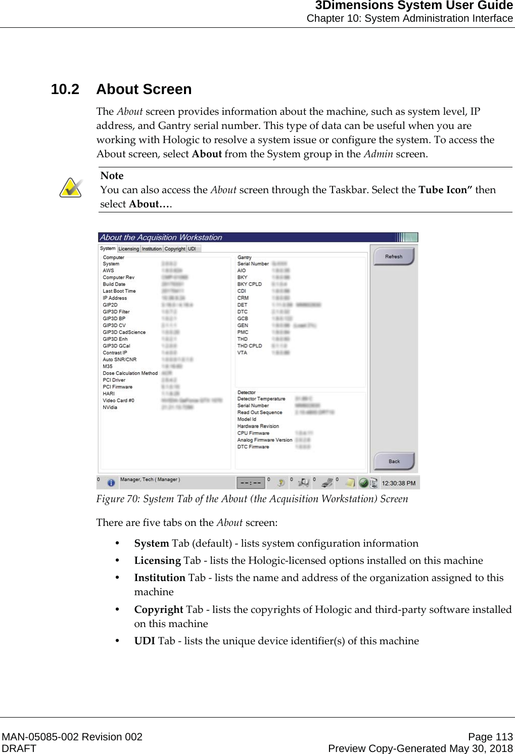
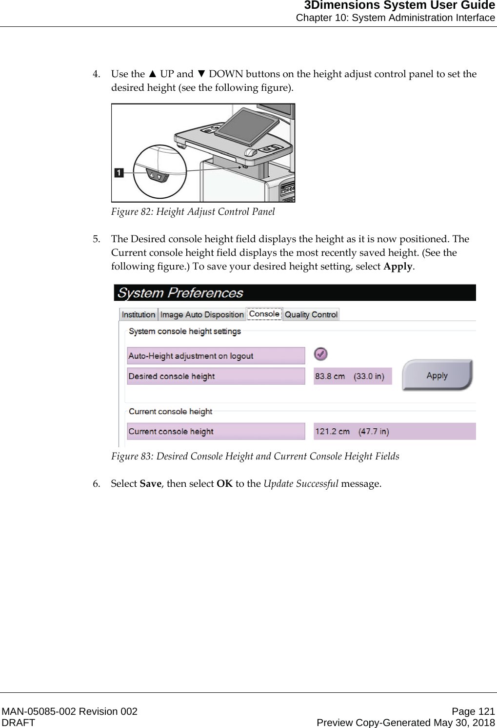
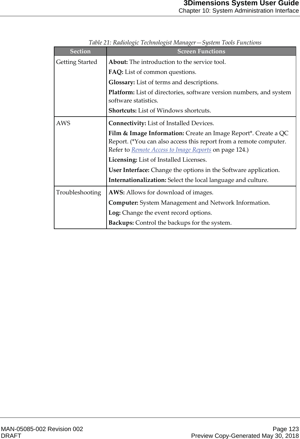
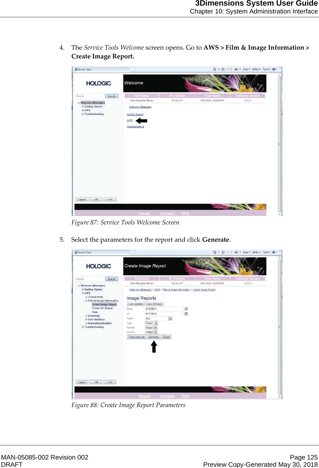
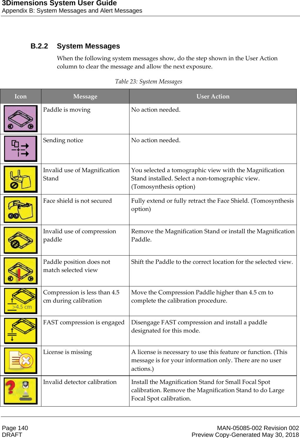
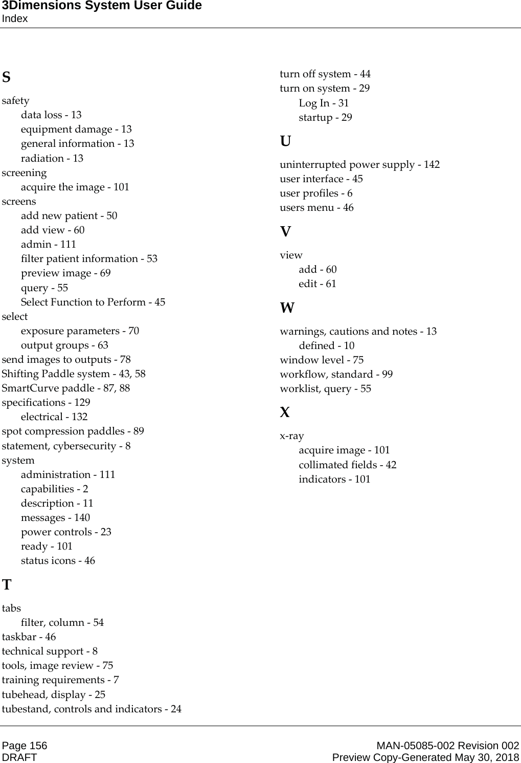
3Dimensions System User GuideChapter 7: AccessoriesMAN-05085-002 Revision 002 Page 85DRAFT Preview Copy-Generated May 30, 20187.2.2 How to Use the Retractable Face ShieldNote Before you make an exposure, make sure the Face Shield is completely extended or completely retracted. To extend the Face Shield, pull the Face Shield away from the C-arm until the device latches in the outer position. To retract the Face Shield: 1. Press a Latch Release (see item 2 in the figure Face Shield Operation on page 85—one on each side). 2. Push the Face Shield toward the C-arm until the device stops.  Figure 56: Face Shield Installation  Figure 57: Face Shield Operation
3Dimensions System User GuideChapter 7: AccessoriesPage 86 MAN-05085-002 Revision 002  DRAFT Preview Copy-Generated May 30, 20187.2.3 How to Install and Remove the Conventional Face Shield  Figure 58: How to Install the Conventional Face Shield To install the Conventional Face Shield: 1. Carefully put the tab ends of the Face Shield (item 1 in the previous figure) into the slots at the front of the tubehead mount. 2. Slide the Face Shield on the tubehead mount until the Face Shield locks. To remove the Conventional Face Shield:  1. Pull the sides of the Face Shield in a horizontal direction (away from the tubehead). 2. Remove the Face Shield.
3Dimensions System User GuideChapter 7: AccessoriesMAN-05085-002 Revision 002 Page 87DRAFT Preview Copy-Generated May 30, 20187.3 Compression Paddles Note Some paddles are optional and may not be included with your system.    The system can identify each paddle and automatically adjust the collimator. Available accessories depend on your system configuration. Table 17: Available Accessories Accessory 2D/BT 2D Screening Routine Screening Paddles  18 x 24 cm  *  * 24 x 29 cm  *  * Small Breast  *  * 18 x 24 cm SmartCurve™  *  * 24 x 29 cm SmartCurve  *  * Contact and Spot Compression Paddles 10 cm Contact  *   15 cm Contact  *   7.5 cm Spot Contact  *  See Note Frameless Spot Contact  *   Magnification Paddles  7.5 cm Spot Mag  *   10 cm Mag  *   15 cm Mag  *   Localization Paddles  10 cm Rectangular Open  *   15 cm Rectangular Open  *   10 cm Perforated  *   15 cm Perforated  *   10 cm Mag Perforated Loc  *   10 cm Mag Localization  *   Ultrasound Paddle  15 cm Large Ultrasound  *   Patient Face Shield  *  * Magnification Stand  *   Localization Crosshair Device  *   Magnification Crosshair Device  *
3Dimensions System User GuideChapter 7: AccessoriesPage 88 MAN-05085-002 Revision 002  DRAFT Preview Copy-Generated May 30, 2018Note On the 2D screening system, only use the 7.5 cm Spot Contact Paddle for compression thickness calibration.    Note The 24 x 29 cm frameless screening paddle, the 24 x 29 cm SmartCurve system paddle, the magnification paddles, and the localization paddles are NOT compatible with the paddle shift function.    7.3.1 Routine Screening Paddles      18 x 24 cm Frameless Screening Paddle 24 x 29 cm Frameless Screening Paddle Small Breast Frameless Paddle    SmartCurve System PaddlesWarning: The SmartCurve™ system paddles do not meet the IEC 60601-2-45 standards for minimum range of movement that require the paddle to compress to 10 mm. To ensure adequate compression of very small or very thin breasts, use the standard flat screening paddle.       18 x 24 cm SmartCurve System Frameless Screening Paddle 24 x 29 cm SmartCurve System Frameless Screening Paddle     Note The SmartCurve system paddles may not be suitable for patients with very small breasts. If the breast cannot be properly immobilized or compressed due to the curvature of the paddles, use the standard flat screening paddles.
3Dimensions System User GuideChapter 7: AccessoriesMAN-05085-002 Revision 002 Page 89DRAFT Preview Copy-Generated May 30, 2018Note The SmartCurve system paddles are not recommended for cleavage views, rolled views, or mosaic views of very large breasts. Use the standard flat screening paddles for these views.    Note The SmartCurve system paddles accommodate most breast sizes. Due to the curvature of the paddles, some patients who would use the smaller standard flat paddle may be more easily positioned using the larger SmartCurve paddle.    Note SmartCurve system paddles are not compatible with FAST Compression mode.    7.3.2 Contact and Spot Compression Paddles    10 cm Contact Frameless Paddle 15 cm Contact Frameless Paddle    7.5 cm Spot Contact Frameless Paddle Spot Contact Frameless Paddle   7.3.3 Magnification Paddles      7.5 cm Spot Magnification Paddle 10 cm Magnification Paddle 15 cm Magnification Paddle   Note You cannot acquire Tomosynthesis images with the Magnification paddles.
3Dimensions System User GuideChapter 7: AccessoriesPage 90 MAN-05085-002 Revision 002  DRAFT Preview Copy-Generated May 30, 20187.3.4 Localization Paddles      10 cm Rectangular Opening Localization Paddle 15 cm Rectangular Opening Localization Paddle 10 cm Magnification Localization Paddle       10 cm Perforated Localization Paddle 15 cm Perforated Localization Paddle 10 cm Magnification Localization Perforated Paddle   7.3.5 Large Ultrasound Paddle  15 cm Large Ultrasound Paddle
3Dimensions System User GuideChapter 7: AccessoriesMAN-05085-002 Revision 002 Page 91DRAFT Preview Copy-Generated May 30, 20187.3.6 How to Install and Remove a Compression PaddleSee the figure How to Install a Compression Paddle on page 91 to install a Compression Paddle: 1. Hold the front of the paddle with one hand in front of the Compression Device. 2. Tilt the paddle (between 30 and 45 degrees), then put the rear of the paddle on the groove in the rear of the Compression Device (item 1). 3. Slide the paddle along the groove until the slots on the top of the paddle are under the locks on the Paddle Clamp (item 2). 4. Compress the Paddle Clamp (item 3) with your free hand. 5. Rotate the paddle up (item 4), then release the Paddle Clamp to lock the paddle.  Figure 59: How to Install a Compression Paddle    See the figure How to Remove the Compression Paddle on page 91 to remove the Compression Paddle: 1. Hold the paddle with one hand while you use the free hand to compress the Paddle Clamp to release the lock (item 1). 2. Lower the paddle (item 2) and remove the paddle from the Compression Device (item 3), then release the Paddle Clamp.  Figure 60: How to Remove a Compression Paddle    7.3.7 Paddle Maintenance and CleaningClean the paddles after each use. Refer to Maintenance and Cleaning on page 105 for cleaning instructions.
3Dimensions System User GuideChapter 7: AccessoriesPage 92 MAN-05085-002 Revision 002  DRAFT Preview Copy-Generated May 30, 20187.3.8 Paddle ShiftThe system allows most paddles to move to the left or right of the center position. The feature helps small-breast examinations with lateral views. When a lateral view is selected, the system automatically moves the collimator for the selected paddle position. Note The 24 x 29 cm frameless screening paddle, the 24 x 29 cm SmartCurve system paddle, and the magnification paddles are NOT compatible with the paddle shift function.    7.3.9 FAST Compression ModeAbout FAST Compression ModeThe Fully Automatic Self-adjusting Tilt (FAST) Compression Mode is for use when the composition of the breast tissue does not allow uniform compression across the complete breast with a flat compression paddle. For these patients, not enough compression can cause an image to appear to be out of focus at the anterior region from both involuntary motion and not enough compression. The FAST Compression mode used with this type of breast provides these features: •Reduced motion artifacts, because the compression is more effective •More uniform compression, from the chest wall to the nipple •Maximum patient comfort, because over compression at the chest wall is prevented  When the FAST Compression mode is selected, the paddle automatically tilts when compression is applied. The paddle starts at the flat position until some compression force is applied. The paddle then tilts until its maximum angle is reached. The FAST Compression mode does not require excessive compression, but you must use enough compression to prevent the movement of the breast. You should use a consistent amount of compression, especially for related left and right views. The FAST Compression mode may not be best for breasts that are equal or symmetrical in thickness from the chest wall to the anterior area of the breast. Note Only the 18 x 24 cm Frameless Screening Paddle and the 24 x 29 cm Frameless Screening Paddle are compatible with FAST Compression Mode.     Note The system beeps when FAST Compression Mode is engaged but is not compatible with the current paddle.
3Dimensions System User GuideChapter 7: AccessoriesMAN-05085-002 Revision 002 Page 93DRAFT Preview Copy-Generated May 30, 2018How to Use the FAST Compression Mode SlideTo engage FAST Compression Mode, push the slide (from either side) until the "F" is visible and the slide clicks into position.  Figure 61: The FAST Compression Mode Slide 7.4 Magnification StandThe Magnification Stand has a breast platform and an abdominal shield. When the Magnification Stand is installed, the grid automatically retracts and the x-ray exposure techniques are set to the Magnification default values. Only use the Magnification paddles when the Magnification Stand is installed (refer to Magnification Paddles on page 89). 7.4.1 How to Install and Remove the Magnification Stand  Figure 62: Installation of the Magnification Stand
3Dimensions System User GuideChapter 7: AccessoriesPage 94 MAN-05085-002 Revision 002  DRAFT Preview Copy-Generated May 30, 2018To Install the Magnification Stand 1. Remove the Face Shield (refer to Patient Face Shields on page 84). 2. Remove the compression paddle (refer to How to Remove the Compression Paddle on page 91). 3. Move the Compression Device completely to the top. 4. Hold the stand on each side just below the black buttons, item 4. Do not press the black buttons. Note The black buttons are used only when removing the Magnification Stand.    Note There are two sets of mounting slots for the Magnification Stand—One set is for 1.8x, and the other set is for 1.5x. See numbers 2 and 3 in the figure C-arm Accessories on page 83.    5. Align the thick black lines on the Magnification Stand with the thick black lines on the C-arm. When these lines meet, the hooks of the Magnification Stand align to the mounting slots on the C-arm. See item 1 in the previous figure. 6. Put the hooks of the Magnification Stand into the C-arm slots. Slide the Magnification Stand down, until the thin black lines on the Magnification Stand and the black line of the C-arm meet. See item 2 in the previous figure. 7. The locking pins slide into holes and lock the device. You hear an audible click. Note If the Magnification Stand is not installed correctly, there is an indicator with a red shaft which protrudes. See item 3 in the previous figure. When the stand is installed correctly, the indicator is retracted.    To Remove the Magnification Stand 1. Remove the Magnification paddle. 2. Hold the handles of the Magnification Stand and press the black buttons. 3. Lift and remove the device from the C-arm.
3Dimensions System User GuideChapter 7: AccessoriesMAN-05085-002 Revision 002 Page 95DRAFT Preview Copy-Generated May 30, 20187.5 Crosshair Devices7.5.1 How to Install and Remove the Localization Crosshair Device  Figure 63: Installation of the Localization Crosshair Device    To Install the Localization Crosshair Device1. Remove the face shield (refer to Patient Face Shields on page 84). 2. Move the Compression Device below the mounting slots, indicated by a crosshair icon. See item 2 in the figure C-arm Accessories on page 83. 3. Hold the crosshair device by the handles and align the thick lines on the device with the line on the C-arm. Compress the release levers. 4. Put the hooks into the C-arm slots. 5. Slide the hooks toward the bottom until the thin black lines on the crosshair meet the black line on the C-arm. 6. Release the levers. The locking pins slide into holes and lock the device in position. To Remove the Localization Crosshair Device1. Compress the release levers. 2. Lift the frame toward the top and remove the hooks from the C-arm slots.
3Dimensions System User GuideChapter 7: AccessoriesPage 96 MAN-05085-002 Revision 002  DRAFT Preview Copy-Generated May 30, 20187.5.2 How to Use the Localization Crosshair Device1. The crosshair device rotates to the left or right of the tubehead. Rotate the device away from the x-ray beam during the exposure acquired with the localization paddle. 2. When you rotate the device back to the front for use, make sure the rotation continues until the device clicks into position. 3. Turn on the light field lamp. 4. Rotate the two crosshair knobs until the shadow on the breast matches the crosshairs on the image that identifies the suspect lesion. 7.5.3 How to Install and Remove the Magnification Crosshair Device  Figure 64: How to Install and Remove the Magnification Crosshair Device    To Install the Magnification Crosshair Device1. Remove the face shield (refer to How to Install and Remove the Conventional Face Shield on page 86). 2. Align the Magnification Crosshair Device with the tubehead. 3. Slide the crosshair device on the rails on each side of the tubehead that are used by the Conventional Face Shield. Make sure the device locks into position. 4. Install the remaining magnification devices. To Remove the Magnification Crosshair Device1. Hold the sides of the device. 2. Pull the device toward you and remove from the tubehead.
3Dimensions System User GuideChapter 7: AccessoriesMAN-05085-002 Revision 002 Page 97DRAFT Preview Copy-Generated May 30, 20187.5.4 How to Align the Crosshair Device Note If the crosshair light rectangle appears skewed to the opening in the paddle, perform this alignment procedure.    1. Install the rectangular localization paddle. 2. Loosen the adjustment lock screw on the bottom of the Crosshair Device. 3. Put a piece of white paper on the image receptor to make the shadows of the crosshairs easier to see. 4. Move the localization paddle approximately 6 cm above the image receptor. 5. Turn on the light field. 6. Rotate the Crosshair Device until the rectangle of light aligns with the opening in the localization paddle. 7. Tighten the adjustment screw.
3Dimensions System User GuideChapter 8: Clinical ProceduresMAN-05085-002 Revision 002 Page 99DRAFT Preview Copy-Generated May 30, 20188: Clinical Procedures Warning: C-arm movement is motorized.      Warning: Keep the hands of the patient away from all buttons and switches at all times.    Warning: Place each footswitch in a position where, when used, they remain in reach of the Emergency Off Switches.    Warning: Position the footswitches to prevent accidental operation by a patient or wheelchair.    8.1 Standard Workflow8.1.1 Preparation1. Select a patient from the worklist, or manually add a new patient. 2. Identify the required procedures. 3. Select the output device set if a different or additional device is needed. 4. Install the paddle. 5. Select the first view. 8.1.2 At the Gantry1. Set C-arm height and rotation angle. 2. Make sure the light field illuminates the correct area. 3. Position the patient and compress the breast. Chapter 8
3Dimensions System User GuideChapter 8: Clinical ProceduresPage 100 MAN-05085-002 Revision 002  DRAFT Preview Copy-Generated May 30, 20188.1.3 At the Acquisition Workstation1. Set the exposure technique. 2. Acquire the image. 3. Release the patient. 4. Preview the image. Look at the Exposure Index to make sure that the exposure is within acceptable range. 5. You can use the Window/Level tool or other image review options during image preview. 6. Accept, Reject, or Pend the image. 7. Perform the Acquisition cycle as required for the requested procedures. 8. If necessary, add an additional view or procedure. 9. Make sure that the patient is safely away from the system after you complete the examination. 10. Close the procedure. 8.2 Screening Procedure Example Figure 65: Example of a Screening Procedure Screen
3Dimensions System User GuideChapter 8: Clinical ProceduresMAN-05085-002 Revision 002 Page 101DRAFT Preview Copy-Generated May 30, 20188.2.1 Position the Patient1. Lift or lower the breast platform for the patient. 2. Move the tubehead to the projection angle. 3. Move the patient to the C-arm. 4. Position the patient as required. 5. Put the arm or hand of the patient on the Patient Handle or against the side of the body. 6. Tell the patient to keep away from system controls. 7. Compress the breast. •When possible, use the footswitch controls to provide hands-free compression control and C-arm height adjustment. •Use the light field lamp as necessary to see the x-ray field.  •Apply compression slowly. As necessary, stop and make the adjustments to patient position. •Use the handwheels for final compression. 8.2.2 Set the Exposure TechniquesSelect the exposure techniques for the procedure. Refer to How to Set the Exposure Parameters on page 70 for information. 8.2.3 Acquire the Exposure1. Confirm that all exposure factors are set correctly. 2. If the system does not display Ready in 30 seconds, verify that the accessories are correctly installed and the paddle is locked into position. When the generator status displays Ready, the system is ready for exposure.     Warning: This system can be dangerous to the patient and the user. Always follow the safety precautions for x-ray exposures.
3Dimensions System User GuideChapter 8: Clinical ProceduresPage 102 MAN-05085-002 Revision 002  DRAFT Preview Copy-Generated May 30, 20183. Press and hold the x-ray button and/or the x-ray footswitch for the full exposure.  During the exposure: •A System Message with the radiation symbol and a yellow background is displayed (see the following figure) •An audible tone continues to sound during the exposure The behavior of the audible tone during a combo exposure has changed to avoid early releases of the x-ray button and/or the x-ray footswitch by users. The audible tone is now a continuous sequence of tones. The tone sounds during the entire combo acquisition from the initiation of the exposure to the end of the conventional view. There is no interruption of the audible tone between breast tomosynthesis and conventional digital mammography exposures. Do not release the exposure switch during the audible tone.  Figure 66: Exposure In Progress 4. When the tone stops and the System Message shows Standby (see the following figure), you can release the x-ray button and/or the x-ray footswitch.  Figure 67: Exposure Complete 5. Release the compression device. If the automatic release feature is set, the compression device automatically lifts after the exposure.
3Dimensions System User GuideChapter 8: Clinical ProceduresMAN-05085-002 Revision 002 Page 103DRAFT Preview Copy-Generated May 30, 20188.3 Procedure for Needle Localization with Tomosynthesis1. Install a Localization Paddle, and install the Crosshair Device at the Tubehead. Be sure that the crosshair guides are out of the x-ray field. 2. Open a new procedure with a Tomo or TomoHD view for your approach. 3. Position the patient and apply compression. 4. Acquire a Tomo Scout. Make sure that the ROI is visible inside the Localization Paddle opening. If not, reposition the patient and repeat. 5. Note the Compression Thickness, and note the thickness of the excess tissue through the opening of the Localization Paddle. 6. Scroll through the reconstruction slices to identify where the lesion is best seen. Note the slice number (each slice is 1 mm in thickness). 7. Place the Acquisition Workstation crosshair on the lesion. 8. To find the coordinates for the Gantry Crosshair Device, scroll through the reconstructions until you can identify the alpha numeric coordinates. 9. Calculate the needle depth:  Value Example Breast Compression Thickness  50 mm (+) Thickness of the tissue through the opening of the paddle  + 7 mm (-) Slice number where the lesion is found  - 30 mm (+) Optional distance past the ROI for the wire  + 5-15 mm (=) Needle depth of the localization wire  32– 42 mm  10. Turn on the collimator light and align the Crosshair Device at the Tubehead to match the Acquisition Workstation crosshair. 11. Position and insert the needle. 12. Move the Crosshair Device guides out of the x-ray field. 13. Acquire another Tomo image to be sure that the needle is in the correct location. To calculate if a correction is necessary, compare the slice number of the point of the needle and the slice number of the lesion. 14. Insert the guide wire through the needle, and then remove the needle, if desired,  leaving the wire in position. 15. If desired, complete the following steps: a. Acquire a Conventional or Tomo view to be sure of correct wire placement. b. Take the orthogonal view to document wire or needle placement (either in Tomo or conventional). 16. Only add one view icon at a time for orthogonal views to remove the possibility of paddle shift due to possible minimal compression.
3Dimensions System User GuideChapter 8: Clinical ProceduresPage 104 MAN-05085-002 Revision 002  DRAFT Preview Copy-Generated May 30, 2018Example: Calculating Needle Depth with TomosynthesisIn this example, use the values from the table on the previous page and refer to the following figure. Calculate the needle depth from the tissue skin line (item 1) rather than from the localization paddle (item 9). Insert the needle a minimum of 27 mm (breast compression + bulging tissue).  Figure 68: Calculating needle depth    Item Description  Example 1  Thickness of the tissue through the opening of the localization paddle  7 mm 2  Thickness measured from the localization paddle to the lesion   3  Lesion slice number (the slice number where lesion is best seen (clearest))  30 mm 4  Thickness measured from the detector to the lesion   5 Slice number 1   6 Needle   7 Lesion   8  Advancing the needle 5 - 15 mm more than the lesion (optional)  5 - 15 mm 9 Localization paddle   10  Thickness of the breast compression from the detector (0 mm) to the localization paddle (50 mm in this example) 50 mm
3Dimensions System User GuideChapter 9: Maintenance and CleaningMAN-05085-002 Revision 002 Page 105DRAFT Preview Copy-Generated May 30, 20189: Maintenance and Cleaning9.1 Cleaning9.1.1 General Information About CleaningBefore each examination, clean and use a disinfectant on any part of the system which touches a patient. Give the attention to the paddles and the image receptor. Caution: Do not use any hot source (like a heating pad) on the image receptor. Be careful with the compression paddles. Inspect the paddles. Replace the paddle when you see damage. 9.1.2 For General CleaningUse a lint-free cloth or pad and apply a diluted dishwashing liquid. Caution: Use the least possible amount of cleaning fluids. The fluids must not flow or run.    If more than soap and water is required, Hologic recommends any one of the following: •10% chlorine bleach and water with one part commercially available chlorine bleach (normally 5.25% chlorine and 94.75% water) and nine parts water •Commercially available isopropyl alcohol solution (70% isopropyl alcohol by volume, not diluted) •3% maximum concentration of hydrogen peroxide solution After you apply any of the above solutions, use a pad and apply a diluted dishwashing liquid to clean any parts which touch the patient. Warning: If a paddle touches possible infectious materials, contact your Infection Control Representative to remove contamination from the paddle.    Caution: To prevent damage to the electronic components, do not use disinfectant sprays on the system.    Chapter 9
3Dimensions System User GuideChapter 9: Maintenance and CleaningPage 106 MAN-05085-002 Revision 002  DRAFT Preview Copy-Generated May 30, 20189.1.3 To Prevent Possible Injury or Equipment DamageDo not use a corrosive solvent, abrasive detergent, or polish. Select a cleaning/disinfecting agent that does not damage the plastics, aluminum, or carbon fiber. Do not use strong detergents, abrasive cleaners, high alcohol concentration, or methanol at any concentration.  Do not expose equipment parts to steam or high temperature sterilization. Do not let liquids enter the internal parts of the equipment. Do not apply cleaning sprays or liquids to the equipment. Always use a clean cloth and apply the spray or liquid to the cloth. If liquid enters the system, disconnect the electrical supply and examine the system before returning it to use. Caution: Wrong cleaning methods can damage the equipment, decrease imaging performance, or increase the risk of electric shock. Always follow instructions from the manufacturer of the product you use for cleaning. The instructions include the directions and precautions for the application and contact time, storage, wash requirements, protective clothing, shelf life, and disposal. Follow the instructions and use the product in the most safe and effective method.
3Dimensions System User GuideChapter 9: Maintenance and CleaningMAN-05085-002 Revision 002 Page 107DRAFT Preview Copy-Generated May 30, 20189.1.4 Acquisition WorkstationHow to Clean the Image Display ScreenAvoid touching the display screen of the Image Display monitor. Use care when cleaning the outer surface of the LCD screen. Always use a clean, soft, lint-free cloth to clean the display area. Microfiber cloths are recommended. •Never use a spray or flow a liquid on the display. •Never apply any pressure to the display area. •Never use a detergent with fluorides, ammonia, alcohol, or abrasives. •Never use any bleach. •Never use any steel wool. •Never use a sponge with abrasives. There are many commercially available products to clean LCD displays. Any of the products free of the ingredients described above and used according to the directions of the manufacturer can be used. How to Clean the Touchscreen DisplayUse a window or glass cleaning product to clean the Touchscreen display. Apply the cleaning product to a cloth, then clean the Touchscreen display. Do not apply the cleaning product to the display without the cloth. How to Clean the KeyboardWipe the surfaces with a CRT wipe. If necessary, clean the keyboard with a vacuum. If liquids enter the keyboard, contact Technical Support for a replacement. How to Clean the Fingerprint ScannerCaution: To protect the Fingerprint Scanner: xDo not apply any liquid product directly on the Fingerprint Scanner window. xDo not use products that contain alcohol. xNever put the Fingerprint Scanner under liquid. xNever apply any pressure to the Fingerprint Scanner window with abrasive material. xDo not push the Fingerprint Scanner window.     To clean the Fingerprint Scanner window, do one of the following: •Apply the adhesive side of cellophane tape, then remove the tape. •Apply a product with ammonia base to a cloth, and clean the Fingerprint Scanner window.
3Dimensions System User GuideChapter 9: Maintenance and CleaningPage 108 MAN-05085-002 Revision 002  DRAFT Preview Copy-Generated May 30, 20189.2 Maintenance9.2.1 Preventive Maintenance Schedules Table 18: User Preventive Maintenance Recommended Frequency Maintenance Task Description  Each Use  Weekly  Biweekly  Monthly  Bimonthly  Semiannually Clean & disinfect paddle  x           Clean & disinfect breast platform  x           Visually inspect all paddles for damage x       Detector Flat Field Calibration *    x         Artifact Evaluation *    x         Phantom Image *   x      Signal to Noise / Contrast to Noise Measurements *  x      Geometry Calibration (Tomosynthesis Option) *       x Compression Thickness Indicator *      x       Visual Checklist *     x    Compression *        x * Refer to Quality Control Manual
3Dimensions System User GuideChapter 9: Maintenance and CleaningMAN-05085-002 Revision 002 Page 109DRAFT Preview Copy-Generated May 30, 2018    Table 19: Service Engineer Preventive Maintenance Maintenance Task Description  Recommended Frequency Semiannually  Annually Clean and Inspect the Gantry and Acquisition Workstation  x   Inspect the radiation shield for chips, cracks, breaks, and for tight attachments.  x   Check all primary power connections  x   Check interlocks, safety and limit switches  x   Inspect/Lubricate C-arm  x   C-arm / Verify all C-arm buttons  x   Verify C-arm and Rotational Calibration  x   Replace Breast Platform Filter  x   Verify Compression Force Calibration  x   Verify Compression Thickness Calibration  x   Inspect LED Collimator Lamp for dust and dirt  x   Clean & lubricate collimator, and worm screws  x   Perform Rotational Brake verification  x   Verify X-ray Field / Light Field Calibration  x   Verify kV Calibration and Tube Current Calibration  x   Check HVL Evaluation  x   Verify Target Dose Verification  x   Verify AEC Exposure Compensation 2D  x   Perform System Resolution Test *  x   Perform Phantom Image Quality Evaluation *  x   Perform Image Artifact Evaluation *  x   Backup Acquisition Workstation files  x   Evaluate UPS Performance Status/ Batteries Status  x   Backup all Calibration Data  x   * Refer to Quality Control Manual
3Dimensions System User GuideChapter 9: Maintenance and CleaningPage 110 MAN-05085-002 Revision 002  DRAFT Preview Copy-Generated May 30, 20189.2.2 About ReclamationReclamation is an automatic function that makes disk space available for storing newly acquired images. Configurable parameters let a given number of images collect before reclamation starts and older images are removed from the system.
3Dimensions System User GuideChapter 10: System Administration InterfaceMAN-05085-002 Revision 002 Page 111DRAFT Preview Copy-Generated May 30, 201810: System Administration Interface10.1 Admin ScreenThis section describes the functions available in the Admin screen. To access all the functions in this screen, log in to the system as a user with administrator, manager, or service permissions. Refer to the table on the following page for descriptions of the Admin screen functions. Note Depending on the license settings for your system, you may see different buttons.    Figure 69: Admin Screen Table 20: Admin Screen Functions Group Button  Function Operators  Manage Operators Add, delete or change Operator information. My Settings Change the information for the current Operator. Procedures  Procedure Editor Add or Edit the procedures, or change the view order for each user. Procedure Order Change the procedure list order. View Editor Set the default view order for a procedure and edit individual views. Contrast Access the contrast enhanced digital mammography functionality. Chapter 10
3Dimensions System User GuideChapter 10: System Administration InterfacePage 112 MAN-05085-002 Revision 002  DRAFT Preview Copy-Generated May 30, 2018Table 20: Admin Screen Functions Group Button  Function Quality Control  Quality Control Select a Quality Control task to perform or mark completed. QC Report Create a QC Report. Test Patterns Select and send the test patterns to output devices. Reject and Repeat Report Create a Reject and Repeat Report. System  System Tools The Interface for Service for the configuration of and identification of problems in the Acquisition Workstation. System Defaults Set the Gantry default values. System Diagnostics Shows the status of all subsystems. Preferences Set the system preferences. About Describes the system. Refer to About Screen on page 113. Exposure Report Create a radiation Exposure Report. Biopsy Devices Lists available biopsy devices. QAS Access the QAS Needle Test screen. Lateral QAS Access the Lateral QAS Needle Test screen. Connectivity  Query Retrieve Query the configured devices. Import Import the data from a DICOM source. Manage Output Groups Add, delete, or edit output groups. Incoming Log Shows log entries for images that do not import during manual import or DICOM store. Archive Send local studies to networked storage or export to removable media devices. You must have permission to access all features. The permission level controls the functions you can change.
3Dimensions System User GuideChapter 10: System Administration InterfaceMAN-05085-002 Revision 002 Page 113DRAFT Preview Copy-Generated May 30, 201810.2 About ScreenThe About screen provides information about the machine, such as system level, IP address, and Gantry serial number. This type of data can be useful when you are working with Hologic to resolve a system issue or configure the system. To access the About screen, select About from the System group in the Admin screen. Note You can also access the About screen through the Taskbar. Select the Tube Icon” then select About….     Figure 70: System Tab of the About (the Acquisition Workstation) Screen There are five tabs on the About screen: •System Tab (default) - lists system configuration information •Licensing Tab - lists the Hologic-licensed options installed on this machine •Institution Tab - lists the name and address of the organization assigned to this machine •Copyright Tab - lists the copyrights of Hologic and third-party software installed on this machine •UDI Tab - lists the unique device identifier(s) of this machine
3Dimensions System User GuideChapter 10: System Administration InterfacePage 114 MAN-05085-002 Revision 002  DRAFT Preview Copy-Generated May 30, 201810.2.1 Licensing TabThe Licensing tab of the About screen shows all the licenses installed on your system. Note Hologic configures some systems to meet specific requirements. Your system configuration may not have all the options and accessories included in this manual.     Figure 71: Licensing Tab of the About Screen    10.3 Change the User Language PreferenceUsers can set the language on the user interface to automatically change to their individual preference when logging in. 1. In the Operators group of the Admin screen, select My Settings. Note You can also access My Settings through the taskbar. Select the User Name area then select My Settings in the pop-up menu.    2. The Users tab of the Edit Operator screen opens. From the Locale field, select a language from the drop-down list. 3. Select Save, then select OK to the Update Successful message. The user interface changes to the selected language.
3Dimensions System User GuideChapter 10: System Administration InterfaceMAN-05085-002 Revision 002 Page 115DRAFT Preview Copy-Generated May 30, 201810.4 Set Auto-Hanging and Auto-PairingTo set the system for Auto-Hanging and Auto-Pairing of images: 1. In the Operators group of the Admin screen, select My Settings. Note You can also access My Settings through the Taskbar. Select the User Name area then select My Settings in the pop-up menu.    2. The Edit Operator screen opens. Select the Workflow tab. •Select the Auto-Hanging check box to show a prior study in 4-up mode automatically. •Select the Auto-Pairing check box to show a prior view in multi-up mode next to a newly captured image.   Figure 72: Enable Auto-Hanging and Auto-Pairing    3. Select Save, then select OK to the Update Successful message. 10.5 Set Multi Line Procedure TabsYou can set the operator preferences to display more of the procedure name in the top of the procedure tabs. To change the procedure tabs from a single line of text to multiple lines of text: 1. In the Operators group of the Admin screen, select My Settings. Note You can also access My Settings through the Taskbar. Select the User Name area then select My Settings in the pop-up menu.    2. The Edit Operator screen opens. Select the Workflow tab.
3Dimensions System User GuideChapter 10: System Administration InterfacePage 116 MAN-05085-002 Revision 002  DRAFT Preview Copy-Generated May 30, 20183. Select the Use Multi Line Procedure Tabs check box.   Figure 73: Enable Multi Line Procedure Tabs    4. Select Save, then select OK in the Update Successful message. 10.6 Enable and Set the Height MemoryUsers can enable and set the acquisition workstation height to automatically change to their individual preference when logging in. To enable and set the height adjust memory: 1. In the Operators group of the Admin screen, select My Settings.  Figure 74: My Settings Button in the Admin Screen    Note You can also access My Settings through the Taskbar. Select the User Name area then select My Settings in the pop-up menu.    2. In the Edit Operator screen, select the Console tab.
3Dimensions System User GuideChapter 10: System Administration InterfaceMAN-05085-002 Revision 002 Page 117DRAFT Preview Copy-Generated May 30, 20183. To enable the height adjust memory, select the radio button to the right of the "Auto-Height adjustment on login" field. A check mark appears. (To disable the height adjust memory, clear the radio button.)   Figure 75: Console Tab of the Edit Operator Screen    4. Use the Ÿ UP and ź DOWN buttons on the height adjust control panel to set the desired height (see the following figure).  Figure 76: Height Adjust Control Panel    5. The Desired console height field displays the height as it is now positioned. The Current console height field displays the most recently saved height. (See the following figure.) To save your desired height setting, select Apply.  Figure 77: Desired Console Height and Current Console Height Fields    6. Select Save, then select OK to the Update Successful message.
3Dimensions System User GuideChapter 10: System Administration InterfacePage 118 MAN-05085-002 Revision 002  DRAFT Preview Copy-Generated May 30, 201810.7 Set Auto-Accept and Auto-Pend ImagesA manager user can configure the system to automatically accept or automatically pend new images. 1. In the System group of the Admin screen, select Preferences. The System Preferences screen opens. 2. Select the Image Auto Disposition tab. 3. Use the drop-down menus to select the auto disposition for each type of image. •Select Manual to manually accept, reject, or pend each newly acquired image. •Select Accept to automatically accept newly acquired images. •Select Pend to automatically pend newly acquired images.  Figure 78: Set Image Auto Disposition    4. Select Save, then select OK to the Update Successful message.
3Dimensions System User GuideChapter 10: System Administration InterfaceMAN-05085-002 Revision 002 Page 119DRAFT Preview Copy-Generated May 30, 201810.8 How to Set the Contrast DefaultsA manager user can configure the default timer periods and the default contrast information. Set the Default Timer Periods 1. From the Procedures group in the Admin screen, select the Contrast button.  Figure 79: I-View 2D Contrast Default Settings 2. Choose the plus (+) or minus (-) buttons to change the Minutes and Seconds for the Waiting Period and Optimal Imaging Period. 3. Select Save. Your selections appear as the default timer settings on the Contrast tab. Set the Default Contrast Information 1. From the Procedures group in the Admin screen, select the Contrast button. 2. Select one or more Contrast agents, Entry routes, and Concentration. See the previous figure. 3. Select Save. Your selections appear as the default options in the Contrast Information dialog box.
3Dimensions System User GuideChapter 10: System Administration InterfacePage 120 MAN-05085-002 Revision 002  DRAFT Preview Copy-Generated May 30, 201810.9 Enable and Set the Default HeightA manager can set the acquisition workstation to automatically return to a default height when a user logs out. To enable and set the default height: 1. In the system group of the Admin screen, select Preferences.  Figure 80: Preferences Button in the Admin Screen  2. In the System Preferences screen, select the Console tab. 3. To enable the default height, select the radio button to the right of the "Auto-Height adjustment on logout" field. A check mark appears. (To disable the default height option, clear the radio button.)  Figure 81: Console Tab of the System Preferences Screen
3Dimensions System User GuideChapter 10: System Administration InterfaceMAN-05085-002 Revision 002 Page 121DRAFT Preview Copy-Generated May 30, 20184. Use the Ÿ UP and ź DOWN buttons on the height adjust control panel to set the desired height (see the following figure).  Figure 82: Height Adjust Control Panel    5. The Desired console height field displays the height as it is now positioned. The Current console height field displays the most recently saved height. (See the following figure.) To save your desired height setting, select Apply.  Figure 83: Desired Console Height and Current Console Height Fields    6. Select Save, then select OK to the Update Successful message.
3Dimensions System User GuideChapter 10: System Administration InterfacePage 122 MAN-05085-002 Revision 002  DRAFT Preview Copy-Generated May 30, 201810.10 System ToolsThe Radiologic Technologist Managers and users with Service permissions can access the System Tools utility. The System Tools utility contains the configuration information about the system. To access the utility, select System Tools from the System group in the Admin screen.  Figure 84: System Tools Button    10.10.1 System Tools for the Radiologic Technologist Manager Figure 85: System Tools Screen
3Dimensions System User GuideChapter 10: System Administration InterfaceMAN-05085-002 Revision 002 Page 123DRAFT Preview Copy-Generated May 30, 2018Table 21: Radiologic Technologist Manager—System Tools Functions Section  Screen Functions Getting Started  About: The introduction to the service tool. FAQ: List of common questions. Glossary: List of terms and descriptions. Platform: List of directories, software version numbers, and system software statistics. Shortcuts: List of Windows shortcuts. AWS  Connectivity: List of Installed Devices. Film & Image Information: Create an Image Report*. Create a QC Report. (*You can also access this report from a remote computer. Refer to Remote Access to Image Reports on page 124.) Licensing: List of Installed Licenses. User Interface: Change the options in the Software application. Internationalization: Select the local language and culture. Troubleshooting  AWS: Allows for download of images. Computer: System Management and Network Information. Log: Change the event record options. Backups: Control the backups for the system.
3Dimensions System User GuideChapter 10: System Administration InterfacePage 124 MAN-05085-002 Revision 002  DRAFT Preview Copy-Generated May 30, 201810.10.2 Remote Access to Image ReportsAccess image reports via a remote computer networked to the system. This function can be useful for sites that do not permit USB downloads of reports directly from the system. Follow these steps to access image reports from a remote computer. You must log in to the System Tools as a Manager-level user for this procedure. 1. Get the IP Address for the system you want to access. You can get the IP Address from your IT administrator or from the system. From the system, go to Select Patient Screen > “Tube Icon” on Taskbar > About… > System Tab > IP Address. Write down the IP Address. 2. Using an internet browser on your remote computer, navigate to http:// [IP address]/Hologic.web/MainPage.aspx. Use the IP Address from step 1.  3. The Service Tools Logon screen opens. Type a Manager-level user name and password, and then click Submit.  Figure 86: Remote Logon Screen for Service Tools
3Dimensions System User GuideChapter 10: System Administration InterfaceMAN-05085-002 Revision 002 Page 125DRAFT Preview Copy-Generated May 30, 20184. The Service Tools Welcome screen opens. Go to AWS > Film & Image Information > Create Image Report.  Figure 87: Service Tools Welcome Screen    5. Select the parameters for the report and click Generate.  Figure 88: Create Image Report Parameters
3Dimensions System User GuideChapter 10: System Administration InterfacePage 126 MAN-05085-002 Revision 002  DRAFT Preview Copy-Generated May 30, 20186. The report shows on the screen. Scroll to the bottom of the report and select either Click to Download (html) or Click to Download (csv) for the file download type. Click Save when prompted.  Figure 89: Create Image Report    7. Select a folder on the computer, and then click Save. 8. Log out from Service Tools when finished. 10.11 Archive Tool The archive feature in the Admin screen lets you: xSend local studies to an archive. xExport studies to removable media.  Figure 90: Archive Button
3Dimensions System User GuideChapter 10: System Administration InterfaceMAN-05085-002 Revision 002 Page 127DRAFT Preview Copy-Generated May 30, 20181. From the Connectivity group in the Admin screen, select the Archive button. The Multi Patient On Demand Archive screen opens. 2. To search for a patient, enter at least two characters in the Search parameters area and select the magnifying glass. A list of patients that match the search criteria is displayed.  Figure 91: Multi Patient On Demand Archive Screen Figure Legend 1. Search parameters 2. Patient List area 3. Patients To Be Archived area 4. Add selection in the Patient List area to the Patients To Be Archived area 5. Remove the selection from the Patients To Be Archived area     To Archive: 1. Select the patients and the procedures to archive. •Select patients from the patient list, or do a search with the search parameters (item 1) and select patients from the search results. Note The Select All button (on the right side of the screen) selects all the patients in the Patient List area. The Clear button (on the right side of the screen) clears selections.    •Select the procedures for each patient. •Select the Down Arrow (item 4) on the screen to move the selected patients to the Patients To Be Archived area (item 3). •Select the Up Arrow (item 5) on the screen to remove the selected patients from the Patients To Be Archived area (item 3).
3Dimensions System User GuideChapter 10: System Administration InterfacePage 128 MAN-05085-002 Revision 002  DRAFT Preview Copy-Generated May 30, 20182. Select a storage device. •Select an option from the Store Device drop-down menu. -OR- •Select the Group List button, then select an option. 3. Select the Archive button. The list in the Patients To Be Archived area copies to the selected archive devices. Note Use the Manage Queue utility in the taskbar to review the archive status.    To Export: 1. Select the patients and the procedures to export. •Select patients from the patient list, or do a search with one of the search parameters (item 1) and select patients from the search results. Note The Select All button (on the right side of the screen) selects all the patients in the Patient List area. The Clear button (on the right side of the screen) clears selections. •Select the procedures for each patient. •Select the Down Arrow (item 4) on the screen to move the selected patients to the Patients To Be Archived area (item 3). •Select the Up Arrow (item 5) on the screen to remove the selected patients from the Patients To Be Archived area (item 3). 2. Select the Export button. 3. In the Export dialog box, select the Target from the drop-down menu of media devices. Figure 92: Export Screen 4. Select other options, if necessary: •Anonymize: to anonymize patient data. •Advanced: to select a folder on your local system to keep the selections, and also to select the Export types. 5. Select the Start button to copy the selected images to the selected device.
3Dimensions System User GuideAppendix A: SpecificationsMAN-05085-002 Revision 002 Page 129DRAFT Preview Copy-Generated May 30, 2018Appen dix A  SpecificationsA.1 Product MeasurementsA.1.1  Tubestand (Gantry with C-Arm)  Figure 93: Tubestand (Gantry with C-arm) Measurements  A.  Height  223 cm (87.8 inches) B.  Width  66 cm (26 inches) C.  Width  173 cm (68 inches) D.  Depth  138 cm (54.25 inches)  Weight  Maximum of 400 kg (882 pounds)  Appendix A
3Dimensions System User GuideAppendix A: SpecificationsPage 130 MAN-05085-002 Revision 002  DRAFT Preview Copy-Generated May 30, 2018A.1.2 Acquisition WorkstationsUniversal Acquisition Workstation Figure 94: Universal Acquisition Workstation Measurements  A.  Width (maximum) with optional articulated display arm extended  136 cm (53.4 inches) - series I UAWS 128 cm (50.3 inches) - series II UAWS  Width (maximum) with standard display arm 94.0 cm (36.9 inches) - series I UAWS 107 cm (42.0 inches) - series II UAWS B.  Depth (maximum) with keyboard tray extended and optional articulated display monitor arm 122 cm (48.4 inches) - series I UAWS, rotated to the side 115 cm (45.1 inches) - series II UAWS, rotated to the side  Depth (maximum) with keyboard tray extended and standard display arm 83.6 cm (32.9 inches) - series I and II UAWS C.  Height (nominal)  219 cm (86.1 inches) after August 2017 204 cm (80.3 inches) before September 2017  Weight (maximum)  209 kg (460 pounds)
3Dimensions System User GuideAppendix A: SpecificationsMAN-05085-002 Revision 002 Page 131DRAFT Preview Copy-Generated May 30, 2018Acquisition Workstation for Mobile Use Figure 95: Mobile Universal Acquisition Workstation Measurements  A.  Width (maximum) with mobile display arm 100 cm (39.5 inches) - series I UAWS 107 cm (42.0 inches) - series II UAWS B.  Depth (maximum) with keyboard tray extended 85 cm (33.5 inches) C.  Height (maximum)  180 cm (71 inches)  Weight (maximum)  179 kg (395 pounds)  A.2  Operation and Storage EnvironmentA.2.1  General Conditions for Operation Temperature Range  20 °C (68 °F) to 30 °C (86 °F) Relative Humidity Range  20% to 80% without condensing moisture
3Dimensions System User GuideAppendix A: SpecificationsPage 132 MAN-05085-002 Revision 002  DRAFT Preview Copy-Generated May 30, 2018A.2.2 Storage EnvironmentGantryTemperature Range  –10 °C (14 °F) to 40 °C (104 °F) Relative Humidity Range  10% to 90% without condensing moisture (Put in a package for storage in a building.) X-ray DetectorTemperature Range  10 °C (50 °F) to 30 °C (86°F) indefinitely 10 °C (50 °F) to 35°C (95 °F) for a maximum of 12 hours Maximum rate of temperature change  Less than 10 °C (50 °F) per hour Relative Humidity Range  10% to 80% without condensing moisture (Put in a package for storage in a building.)    Acquisition WorkstationTemperature Range  –10 °C (14 °F) to 40 °C (104 °F) Relative Humidity Range  10% to 90% without condensing moisture (Put in a package for storage in a building.) A.3 Radiation Shield Radiation Shield Lead (Pb) equivalent  0.5 mm lead for x ray energy to 35 kV  A.4 Electrical InputA.4.1 Tubestand Mains Voltage  200/208/220/230/ 240 VAC ±10% Mains Impedance  Maximum line impedance not to exceed 0.20 ohms for 208/220/230/240 VAC, 0.16 ohms for 200 VAC Mains Frequency  50/60 Hz ±5% Average Current over 24 Hours  < 5 A Peak Line Current  4 A (65 A maximum for < 5 seconds)
3Dimensions System User GuideAppendix A: SpecificationsMAN-05085-002 Revision 002 Page 133DRAFT Preview Copy-Generated May 30, 2018A.4.2 Acquisition Workstation Mains Voltage  100/120/200/208/220/230/240 VAC ±10% Mains Frequency  50/60 Hz ±5% Power Consumption  < 1000 watts Duty Cycle (Standard Acquisition Workstation)  10% ~ 6 minutes per hour or 2 minutes on, 18 minutes off Overcurrent Protection  8A A.5 Tubestand Technical InformationA.5.1 C-Arm Rotation Range  Conventional Mammography:  +195° +3°/–0.5° to 0° ±0.5° to –155° +0.5°/–3° Tomosynthesis option:  +180° ±0.5° to 0° ±0.5° to –140° ±0.5° Absolute Angular Position  accurate to ±0.5° Rotation Acceleration  18°/s2 +18/-9% Rotation Deceleration  18°/s2 +18/-9% Rotational Positioning Angular Velocity  18°/s ±25%  Note The angular velocity is the average of the velocity of the tube arm rotating clockwise between 0° and 90° or rotating counterclockwise between 90° and 0°. The angular velocity does not include the time to accelerate from zero velocity and decelerate to zero velocity.  Source-to-Image Distance (SID)  70.0 cm ±1.0 cm (27.6 inches ±0.4 inches) (Focus position deviation is ±5 mm) Patient Support (non-magnification)    Vertical Position Lower Limit  70.5 cm +5.1/-0 cm (27.75 inches +2.0/-0 inches)  Vertical Position Upper Limit  141 cm +0/-17.8 cm (55.5 inches +0/-7.0 inches)
3Dimensions System User GuideAppendix A: SpecificationsPage 134 MAN-05085-002 Revision 002  DRAFT Preview Copy-Generated May 30, 2018A.5.2 Compression Manual Compression Force  Maximum of 300 N (67.4 pounds) Motorized Compression  Functions in three operating modes: Pre-compression, Full-Range, Dual Compression. User selectable through software. Pre-Compression Force  15 pounds to 30 pounds (67 to 134 N), motorized Full Range Compression Force  20 pounds to 40 pounds (89 to 178 N), motorized Dual Mode Compression  Provides Pre-Compression force upon first activation of compression switch; then, if switch is activated within 2 seconds, the force is increased incrementally for each additional switch activation, up to the user selected full compression force. Compression Controls  Up/Down controls on both sides of C-arm and on 2-position footswitch (Motorized). Handwheel on both sides of Compression Device (Manual). Compression Release  Manual Motorized Release controlled by push-buttons on both sides of the C-arm. Automatic Compression Release  User selectable automatic release mode raises Compression Device upon exposure termination. Down Motion Variable Speed  4.2 cm/s ±15% (1.66 inches/s ±15%) Compression Force Display  Two LCDs on the Compression Device show the compression force through the range of 18 N to 300 N in 1 N increments (4 pounds to 67 pounds in 1 pound increments). Compression Force Display Accuracy  ±20 N (±4.5 pounds) Compression Thickness Display  Two LCDs on the Compression Device measure compression thickness in 0.1 cm increments. The display is visible from both sides of the patient. Compression Thickness Accuracy  ±0.5 cm (±0.2 inches) for thicknesses between 0.5 cm and 15 cm (5.9 inches) Breast Tomosynthesis Compression Thickness Standard resolution tomosynthesis Maximum: 24 cm (restricted by compression device geometry) High resolution tomosynthesis Maximum: 15 cm (restricted by DICOM limitations) Compression Paddles  Compression Paddles are transparent. The paddles are composed of polycarbonate resin or the equivalent. With compression applied, paddle deflection from a plane parallel to the patient support surface shall be less than or equal to 1.0 cm.
3Dimensions System User GuideAppendix A: SpecificationsMAN-05085-002 Revision 002 Page 135DRAFT Preview Copy-Generated May 30, 2018A.5.3 X-ray Tube Focal Spot  Large (0.3 mm) Nominal Small (0.1 mm) Nominal Tube Voltage  20 kV to 49 kV Anode Material  Tungsten X-Ray Window  Beryllium 0.63 mm Tube leakage test conditions  49 kVp, 2.0 mA     A.5.4  X-ray Beam Filtration and Output Filtration Five-position filter wheel: Position 1: Rhodium, 0.050 mm ±10% Position 2: Aluminum, 0.70 mm (nominal) (Tomosynthesis option) Position 3: Silver, 0.050 mm ±10% Position 4: Copper, 0.3mm Position 5: Lead (provided for servicing)    kV/mA RangeTable 22: Maximum mA Setting as a Function of kV kV  LFS mA  SFS mA 20 100  30 21 110  30 22 110  30 23 120  30 24 130  30 25 130  40 26 140  40 27 150  40 28 160  40 29 160  40 30 170  50 31 180  50
3Dimensions System User GuideAppendix A: SpecificationsPage 136 MAN-05085-002 Revision 002  DRAFT Preview Copy-Generated May 30, 2018Table 22: Maximum mA Setting as a Function of kV kV  LFS mA  SFS mA 32 190  50 33 200  50 34 200  50 35 200  50 36 190  50 37 180  50 38 180  50 39 180  50 40 170   41 170   42 160   43 160   44 150   45 150   46 150   47 140   48 140   49 140      mAs Steps (Table 1, default)  4, 5, 6, 7, 8, 9, 10, 12, 14, 16, 18, 20, 22, 25, 30, 32.5, 35, 37.5, 40, 42.5, 45, 47.5, 50, 52.5, 55, 57.5, 60, 62.5, 65, 67.5, 70, 75, 80, 85, 90, 95, 100, 120, 140, 160, 180, 200, 220, 240, 260, 280, 300, 320, 340, 360, 380, 400, 420, 440, 460, 480, 500    Attenuation of Carbon FiberImage Receptor  < 0.3 mm Al Magnification Platform  < 0.3 mm Al
3Dimensions System User GuideAppendix A: SpecificationsMAN-05085-002 Revision 002 Page 137DRAFT Preview Copy-Generated May 30, 2018A.5.5 X-ray Collimation Collimation Fields  7.0 cm x 8.5 cm  10 cm x 10 cm  15 cm x 15 cm  18 cm x 24 cm 18 cm x 29 cm (Tomosynthesis option) 24 cm x 29 cm     A.5.6 Light Field Indication Light Field to X Ray Congruency  Within 2% of SID     A.5.7 X-ray Generator Type Constant Potential High Frequency Inverter Rating  7.0 kW, maximum (isowatt), 200 mA at 35 kV Electrical Power Capacity 9.0 kW maximum kV Range  20 kV to 49 kV in 1 kV increments kV accuracy  ±2%, over range 20-49 kVp mAs Range  3.0 mAs to 500 mAs in Manual Mode mAs (8 mAs minimum in AEC Mode) mAs Accuracy  ±(10% + 0.2 mAs) mA Range  10 mA to 200 mA, Large Focal Spot 10 mA to 50 mA, Small Focal Spot
3Dimensions System User GuideAppendix A: SpecificationsPage 138 MAN-05085-002 Revision 002  DRAFT Preview Copy-Generated May 30, 2018A.6  Imaging System Technical InformationA.6.1 Image Receptor Fluid Ingress  No fluid from accidental spillage on the Image Receptor may seep inside. Deflection  Does not exceed 1.0 mm at maximum compression. Active Imaging Area  Not less than 23.3 cm by 28.5 cm (9.2 inches x 11.2 inches) DQE Conventional Mammography  Not less than 50% at 0.2 lp/mm Not less than 15% at the Nyquist limit DQE (Tomosynthesis option)  Not less than 30% at 0.2 lp/mm Not less than 15% at the Nyquist limit Dynamic Range and Linearity  Detector Subsystem response is linear with linearity of 0.999 over a dynamic range of 400:1 in x-ray exposure. Uniformity  Detector Subsystem can correct pixel-to-pixel gain variations.  For conventional mammography procedures, the uniformity of flat field image response of the detector shall be no greater than 2% after gain calibration is applied over an exposure range of 0.5 mR to 200 mR.
3Dimensions System User GuideAppendix B: System Messages and Alert MessagesMAN-05085-002 Revision 002 Page 139DRAFT Preview Copy-Generated May 30, 2018Appen dix B  System Messages and Alert MessagesB.1  Error Recovery and TroubleshootingMost faults and alert messages are cleared without result to your workflow. Follow the instructions on the screen or fix the condition then clear the status from the Taskbar. Some conditions require a system restart or indicate that more action is necessary (for example, to call Hologic Technical Support). This appendix describes the message categories and your actions to return the system to normal operation. If errors repeat, contact Hologic Technical Support. B.2  Types of MessagesB.2.1 Fault LevelsEach Message has a particular set of the following characteristics: •Aborts an exposure in progress (yes/no) •Prevents an exposure from starting (yes/no) •Displays a message to the user on the Acquisition Workstation (yes/no) •May be reset by the user (yes/no) •May be reset automatically by the system (yes/no) Displayed MessagesAll displayed messages will be shown in the user’s selected language. Any message which aborts an exposure or prevents an exposure from starting will always display a message directing the user’s actions required to proceed. Additional Message InformationTechnical information about the message is available in the log file. Some messages always show as a critical fault (a system restart is necessary). These messages result from a condition which prevents an exposure, and which cannot be reset by the user or the system. Appendix B
3Dimensions System User GuideAppendix B: System Messages and Alert MessagesPage 140 MAN-05085-002 Revision 002  DRAFT Preview Copy-Generated May 30, 2018B.2.2 System MessagesWhen the following system messages show, do the step shown in the User Action column to clear the message and allow the next exposure. Table 23: System Messages Icon  Message  User Action  Paddle is moving  No action needed.  Sending notice  No action needed.  Invalid use of Magnification Stand You selected a tomographic view with the Magnification Stand installed. Select a non-tomographic view. (Tomosynthesis option)  Face shield is not secured  Fully extend or fully retract the Face Shield. (Tomosynthesis option)  Invalid use of compression paddle Remove the Magnification Stand or install the Magnification Paddle.  Paddle position does not match selected view Shift the Paddle to the correct location for the selected view.  Compression is less than 4.5 cm during calibration Move the Compression Paddle higher than 4.5 cm to complete the calibration procedure.  FAST compression is engaged  Disengage FAST compression and install a paddle designated for this mode.  License is missing  A license is necessary to use this feature or function. (This message is for your information only. There are no user actions.)  Invalid detector calibration  Install the Magnification Stand for Small Focal Spot calibration. Remove the Magnification Stand to do Large Focal Spot calibration.
3Dimensions System User GuideAppendix B: System Messages and Alert MessagesMAN-05085-002 Revision 002 Page 141DRAFT Preview Copy-Generated May 30, 2018Table 23: System Messages Icon  Message  User Action  Invalid geometry calibration  Repeat the geometry calibration before you try to take an exposure. (Tomosynthesis option)  Configuration file is missing  Applies to Service Personnel.  Waiting for Detector  No action needed.  System in Test Mode  Applies to Service Personnel.  Tube needs to be manually positioned (move to 0 degrees) Rotate the C-arm to 0 degrees.  Tube needs to be manually positioned (move to -15 degrees) Rotate the C-arm to -15 degrees.  Tube needs to be manually positioned (move to 15 degrees) Rotate the C-arm to +15 degrees.  The Emergency Stop switch has been engaged. Turn the Emergency Off switch one-quarter turn to reset the switch.  Compression too low for tomo reconstructions. Move the Compression Paddle higher than 0.5 cm to take tomography exposures.
3Dimensions System User GuideAppendix B: System Messages and Alert MessagesPage 142 MAN-05085-002 Revision 002  DRAFT Preview Copy-Generated May 30, 2018B.3 UPS Messages Note The User Guide for the UPS is supplied with the system. Refer to the UPS User Guide for complete instructions.    The LCD in the UPS shows the power status.  Figure 96: UPS LCD Display Figure Legend 1. UPS Mode 2. UPS Load 3. UPS Efficiency 4. UPS Battery level  If the UPS battery expires, the Mode icon changes as shown. Contact your service representative to replace the battery.
3Dimensions System User GuideAppendix C: Use of Mobile SystemMAN-05085-002 Revision 002 Page 143DRAFT Preview Copy-Generated May 30, 2018Appen dix C  Use of Mobile SystemThis appendix describes the system installed in a mobile environment. C.1  Conditions for Safety and Other PrecautionsAn acceptable, stable, clean VAC power source is required to make sure that the system meets all its performance specifications. Where available, shore power correctly supplied to the system provides the best performance. If a mobile power generator is used, you must keep the specifications for input power during all load conditions. Warning: The radiation shield is not approved for mobile use and is not provided. The coach manufacturer must provide adequate shielding.    Caution: When shore power is unavailable, mobile power sources that provide equivalent performance may be employed. (Refer to Specifications for Mobile Use on page 144.) Proper system function and performance can only be ensured if continuous true sinusoidal VAC power is supplied per the system power input specifications and loading characteristics. Intermittently, the power source must provide 65 Amps at 208 VAC for a minimum of 5 seconds, and 4 Amps maximum continuous otherwise. This load must be supported once every 30 seconds. In the event of shore or mobile power service interruption, the UPS must be capable of providing the operational power described above for a minimum of 4 minutes. Acquisition Workstation and Gantry power must be fed on separate dedicated circuits. The use of an uninterruptible power supply with active line conditioner is recommended on each power circuit. Accordingly, all ancillary mobile coach power should be distributed by other circuits. The electrical installation must be verified to meet system power input specifications and IEC 60601-1 safety requirements after initial installation and upon each relocation of the mobile coach.    Caution: The temperature and humidity inside the vehicle must be maintained at all times. Do not allow environmental conditions to exceed stated specifications when the unit is not in use.    Caution: Voltages cannot change by more than ±10% when the x-ray unit or other equipment (for example, heating or air conditioning) is operated.     Appendix C
3Dimensions System User GuideAppendix C: Use of Mobile SystemPage 144 MAN-05085-002 Revision 002  DRAFT Preview Copy-Generated May 30, 2018Caution To avoid image artifacts from occurring: xCare should be exercised not to locate or park the mobile coach near sources of high power (such as power transmission lines and outdoor transformers). xMake sure that any mobile power generator, uninterruptible power system (UPS), or voltage stabilizer is at least 3 meters (10 feet) from the closest point of the image detector travel.     C.2  Specifications for Mobile UseThe following system specifications are for mobile use only. For all other specifications, refer to the section Specifications on page 129. C.2.1  Shock and Vibration Limits Vibration Limit  Maximum of 0.30 G (2 Hz to 200 Hz), measured at the point where the system mounts to the coach. Shock Limit  Maximum of 1.0 G (1/2 sine pulse), measured at the point where the system mounts to the coach. An “air ride” coach suspension is recommended.  C.2.2 Coach EnvironmentOperation EnvironmentTemperature Range  20 °C (68 °F) to 30 °C (86 °F) Relative Humidity Range  20% to 80% without condensing moisture    Non-operating/Transit EnvironmentTemperature Range  10 °C (50 °F) to 35 °C (95 °F) for a maximum of 12 hours 10 °C (50 °F) to 30 °C (86 °F) indefinitely Maximum Rate of Temperature Change  <10 °C/hr. Relative Humidity Range  10% to 80% without condensing moisture
3Dimensions System User GuideAppendix C: Use of Mobile SystemMAN-05085-002 Revision 002 Page 145DRAFT Preview Copy-Generated May 30, 2018C.3 Electrical InputC.3.1 Gantry Mains Voltage  200/209/220/230/ 240 VAC ±10% Mains Impedance  Maximum line impedance not to exceed  0.20 ohms for 208/220/230/240 VAC,  0.16 ohms for 200 VAC Mains Frequency  50/60 Hz ±5% Average Current over 24 Hours  < 5 A Peak Line Current  4 A (65 A maximum for 3 seconds)  C.3.2 Acquisition Workstation Mains Voltage  100/120/200/ 208/220/230/ 240 VAC ±10% Mains Frequency  50/60 Hz ±5% Power Consumption  < 1000 watts
3Dimensions System User GuideAppendix C: Use of Mobile SystemPage 146 MAN-05085-002 Revision 002  DRAFT Preview Copy-Generated May 30, 2018C.4  Prepare the System for TravelBefore travel, perform these steps: 1. Rotate the C-arm to 0 degrees (CC position). 2. Lower the C-arm to its lowest position. 3. Turn off the system through the user interface. 4. Place the mouse in the keyboard tray. 5. Lock the keyboard tray (see the following figures): a. Close the tray. b. Find the knob under the tray. c. Turn the knob 90° until the knob fits into the lock. Position A in the following figure shows the locked position.  Figure 97: Keyboard Tray Lock Knob  Figure 98: Keyboard Tray Lock Knob  Figure 99: Tray Lock Release from Locked (A) to Unlocked (D)
3Dimensions System User GuideAppendix C: Use of Mobile SystemMAN-05085-002 Revision 002 Page 147DRAFT Preview Copy-Generated May 30, 20186. If using the mobile Universal Acquisition Workstation, lock the swivel display using the knobs provided (see the following figure).  Figure 100: Swivel Lock Knobs for Image Display Monitor on Mobile Universal Acquisition Workstation  7. Lower the work surface to the minimum height. 8. Remove all system accessories. 9. Put all accessories in a safe storage area.  C.5  Prepare the System for Use1. Unlock the keyboard tray: a. Find the knob under the tray. b. Pull the knob down. c. Turn the knob 90°. This position keeps the latch open. Position D (in the following figure) shows the unlocked position.  Figure 101: Tray Lock Release from Locked (A) to Unlocked (D)
3Dimensions System User GuideAppendix C: Use of Mobile SystemPage 148 MAN-05085-002 Revision 002  DRAFT Preview Copy-Generated May 30, 20182. Pull the tray out, if needed. 3. If using the mobile Universal Acquisition Workstation, unlock the swivel display (see the following figure).  Figure 102: Swivel Lock Knobs for Image Display Monitor on Mobile Universal Acquisition Workstation  C.6  Test the System after TravelC.6.1  Mobile System Controls and Functional TestsPerform the Controls and Functional Tests. Refer to Perform the Functional Tests on page 32. •Compression Up/Down •Compression Release •C-arm Rotation •C-arm Up/Down •Collimator Override •Light Field Lamp •Shifting Paddle System •Emergency Off Switches C.7 Quality Control TestsRefer to your quality control manual for quality system checks.
3Dimensions System User GuideAppendix D: Dose InformationMAN-05085-002 Revision 002 Page 149DRAFT Preview Copy-Generated May 30, 2018Appen dix D  Dose InformationD.1 EUREF Dose TablesNotes This information is only applicable for the European Union. The following values are for the default dose tables.    The following tables show typical dose values when operating the system in 2D and in BT imaging modes. The tables follow the procedures given in the European guidelines for quality assurance in breast cancer screening and diagnosis, Fourth edition: section 2a.2.5.1 Dosimetry, and Appendix 5: Procedure for determination of average glandular dose.    Table 24: 2D Dose (EUREF) Phantom cm kV Anode  Filter  EUREF dose (mGy) 2.0 cm PMMA  2.1  25  W  0.05 mm Rh  0.55 3.0 cm PMMA  3.2  26  W  0.05 mm Rh  0.75 4.0 cm PMMA  4.5  28  W  0.05 mm Rh  1.05 4.5 cm PMMA  5.3  29  W  0.05 mm Rh  1.42 5.0 cm PMMA  6  31  W  0.05 mm Rh  2 6.0 cm PMMA  7.5  31  W  0.05 mm Ag  2.7 7.0 cm PMMA  9  34  W  0.05 mm Ag  3.1    Table 25: BT Dose (EUREF) Phantom cm kV Anode  Filter  EUREF dose (mGy) 2.0 cm PMMA  2.1  26  W  0.7 mm Al  1 3.0 cm PMMA  3.2  28  W  0.7 mm Al  1.15 4.0 cm PMMA  4.5  30  W  0.7 mm Al  1.5 4.5 cm PMMA  5.3  31  W  0.7 mm Al  2.00 5.0 cm PMMA  6  33  W  0.7 mm Al  2.5 6.0 cm PMMA  7.5  36  W  0.7 mm Al  3.9 7.0 cm PMMA  9  42  W  0.7 mm Al  5.15 Appendix D
3Dimensions System User GuideAppendix D: Dose InformationPage 150 MAN-05085-002 Revision 002  DRAFT Preview Copy-Generated May 30, 2018   Table 26: CEDM Dose (EUREF) Phantom cm kV Anode  Filter  EUREF dose (mGy) 2.0 cm PMMA  2.1  26/45  W  0.05/0.3 mm Rh/Cu  0.83 3.0 cm PMMA  3.2  26/45  W  0.05/0.3 mm Rh/Cu  1.1 4.0 cm PMMA  4.5  28/45  W  0.05/0.3 mm Rh/Cu  1.6 4.5 cm PMMA  5.3  29/49  W  0.05/0.3 mm Rh/Cu  2.1 5.0 cm PMMA  6  31/49  W  0.05/0.3 mm Rh/Cu  3.0 6.0 cm PMMA  7.5  32/49  W  0.05/0.3 mm Ag/Cu  4.1 7.0 cm PMMA  9  33/49  W  0.05/0.3 mm Ag/Cu  4.7
3Dimensions System User GuideGlossary of TermsMAN-05085-002 Revision 002 Page 151DRAFT Preview Copy-Generated May 30, 201811: Glossary of TermsACRAmerican College of Radiology AECAutomatic Exposure Control AnnotationsMarkings on an image to indicate an area of interest. BTBreast Tomosynthesis. An imaging procedure that provides information about the breast in three dimensions CEDMContrast Enhanced Digital Mammography CollimatorA device at the x-ray tube to control the x-ray beam exposure area. Conventional MammographySingle projection x-ray images of views for screening and diagnostic purposes C-ViewA licensed Hologic feature where a digital mammography (DM) image is generated from data acquired during a breast tomosynthesis (BT) scan DICOMDigital Imaging and Communications in Medicine DMDigital Mammography (2D) EMCElectromagnetic Compatibility FAST PaddleFully Automatic Self-adjusting Tilt Paddle FDAFood and Drug Administration (in the United States) GridAn element within the Digital Image Receptor that reduces scatter radiation during the exposure Image ReceptorAssembly of the x-ray detector, x-ray scatter reduction grid, and carbon fiber cover Intelligent 2DA licensed Hologic feature where a high-resolution digital mammography (DM) image is generated from data acquired during a high resolution breast tomosynthesis (BT) scan I-ViewA licensed feature for 2D Contrast Enhanced Digital Mammography MPPSModality Performed Procedure Step MQSAMammography Quality Standards Act NoticeAnnotations and comments per image communicated between Diagnostic Review Workstations, Technologist Workstations, and Acquisition Workstations PACSPicture Archiving and Communications System. A computer and network system that transmits and archives digital medical images. PendThe action taken on an image to mark the image if the Technologist is not positive about the image quality (pended images must be Accepted or Rejected before the procedure is closed)
3Dimensions System User GuideGlossary of TermsPage 152 MAN-05085-002 Revision 002  DRAFT Preview Copy-Generated May 30, 2018Projection ImageOne of a group of breast tomosynthesis images taken at different projection angles and used to produce the final reconstructed image ReclamationAutomatic removal of patient images and related information to allow storage of new patient image acquisitions RFRadio Frequency ROIRegion of Interest SIDSource to Image Distance TomosynthesisAn imaging procedure that combines a number of breast images taken at different angles. The tomosynthesis images can be reconstructed to show focal planes (slices) within the breast. UDIA United States Food and Drug Administration program for Unique Device Identification (UDI). For more information about UDI, go to http://www.fda.gov/MedicalDevices/DeviceRegulationandGuidance/UniqueDeviceIdentification/UDIBasics/default.htm. UPSUninterruptible Power Supply USBUniversal Serial Bus
3Dimensions System User GuideIndexMAN-05085-002 Revision 002 Page 153DRAFT Preview Copy-Generated May 30, 2018Index2 2D contrast - 79 2D contrast settings - 82, 119 A about (acquisition workstation) screen - 113 accept images - 71, 73, 118 accept rejected images - 73 accessories - 83 compression paddles - 87 crosshair devices - 95 face shields - 84 install on C-arm - 83 magnification stand - 93 acquire images - 71, 101 acquisition modes - 70 Acquisition Workstation about (acquisition workstation) screen - 113 maintenance - 107 add new patient - 50 procedure - 59 view - 60 admin screen - 111 about (acquisition workstation) screen - 113 admin button - 55 functions - 111 remote access to image reports - 124 alerts - 139 archive - 64 auto-hanging, auto-pairing - 115 Automatic Exposure Control buttons - 25 Sensor position - 25 auto-rotation - 39, 41 C calibrations, perform - 45 C-arm auto-rotation - 39, 41 controls and indicators - 24, 26 displays - 25 rotation and movement - 34 slots for accessories - 83 cine tab - 77 circuit breaker Gantry - 23 clinical procedures - 99 close patient - 62 procedure - 62 collimator override - 42 programmed to paddle - 87 columns tab - 55 comments tab - 77 compression controls and displays - 25 FAST compression mode - 92 paddles - 87 release - 101 specifications - 134 compression force, range - 25 computer power button - 23 contact paddles - 89 contrast procedures - 79 contrast settings - 82, 119 controls C-arm - 26, 27 collimator override - 42 compression - 27 compression brake - 33 footswitches, AWS - 27 Gantry Tubestand - 24 handwheels - 25 indicators - 23 light field lamp - 42 system - 23 conventional face shield, install - 86 custom output - 64 cybersecurity statement - 8 D data loss - 13 delete patient - 53 display
3Dimensions System User GuideIndexPage 154 MAN-05085-002 Revision 002  DRAFT Preview Copy-Generated May 30, 2018clean - 107 compression force - 25 preview image - 69 thickness - 25 types of images selection - 77 window level - 75 dose information - 149 EUREF dose tables - 149 E edit patient information - 51 user information - 46 view - 61 Emergency Off Switch - 17, 23, 24 functional test - 32 export - 65, 126 exposure parameters - 70 sequence - 101 techniques, set - 70 F face shield - 84 FAST compression mode - 92 faults - 139 filter tab - 54 other functions - 54 filter, information options - 53 fingerprint scanner - AWS - 31 footswitches, AWS - 27 function, select to perform - 45 functional tests - 32 Emergency Off Switch - 17, 44 G generator tab, set techniques - 70 H Hologic technical support - 105 I images accept - 71, 73, 118 acquisition mode - 70 output options - 78 preview - 69 reject - 71 remote access to image reports - 124 review - 74 review tools - 62, 75 store - 71, 118 Implant Displaced views - 60 Implant Present button - 57 indicators - 23 install compression paddles - 91 conventional face shield - 86 localization crosshair device - 95 magnification crosshair device - 96 Magnification Stand - 93 retractable face shield - 84 Intelligent 2D - 5 international symbols - 9 I-View - 79 I-View settings - 82, 119 L label locations - 21 laser film printer, isolation requirements - 13 licenses - 114 light field lamp use - 101 localization crosshair device align - 97 install and remove - 95 use - 96 localization paddles - 90 Log In - 31 fingerprint scanner - 31 Log Out - 55 M magnification crosshair device, install and remove - 96 magnification paddles - 89 Magnification Stand - 93 install and remove - 93 maintenance
3Dimensions System User GuideIndexMAN-05085-002 Revision 002 Page 155DRAFT Preview Copy-Generated May 30, 2018general - 105 manage alarms - 46 notices - 46 output groups - 63 messages and alerts - 139 MLO rotation - 41 mobile system QC tests - 148 safety - 143 specifications - 144 test after travel - 148 My Settings icon - 46 N needle localization - 103 Notices tab - 77 O On/Off button - 23 on-demand outputs - 64 open patient procedure - 50 output devices custom output - 64 manage output groups - 46 output groups - 78 taskbar icons - 46 output groups, manage - 78 output groups, select - 63 outputs, on-demand - 64 P paddle shift - 43, 58 paddle shift buttons - 25 paddles compression - 89 install - 91 remove - 91 shift - 25, 43, 58 shift to new position - 58 SmartCurve paddle - 87, 88 patient add - 50 close - 62 delete - 53 edit information - 51 face shield - 84 filter - 53 open - 50 position - 101 pended image, accept or reject - 73 permissions, by user group - 122 power button - 23 prerequisites for system use - 6 preview image screen - 69 print - 66 procedure screen - 56 procedures add - 59 close - 62 Q quality control requirements - 7 quality control tasks, perform - 45 query worklist - 55 R radiation safety - 13 reject images - 71 remote access to image reports - 124 remove compression paddles - 91 conventional face shield - 86 localization crosshair device - 95 magnification crosshair device - 96 Magnification Stand - 93 retractable face shield - 84 view - 60 requirements quality control - 7 skills needed - 6 training - 7 retractable face shield install - 84 use - 85 review images - 74 rejected image - 73 ROI tab - 77
3Dimensions System User GuideIndexPage 156 MAN-05085-002 Revision 002  DRAFT Preview Copy-Generated May 30, 2018S safety data loss - 13 equipment damage - 13 general information - 13 radiation - 13 screening acquire the image - 101 screens add new patient - 50 add view - 60 admin - 111 filter patient information - 53 preview image - 69 query - 55 Select Function to Perform - 45 select exposure parameters - 70 output groups - 63 send images to outputs - 78 Shifting Paddle system - 43, 58 SmartCurve paddle - 87, 88 specifications - 129 electrical - 132 spot compression paddles - 89 statement, cybersecurity - 8 system administration - 111 capabilities - 2 description - 11 messages - 140 power controls - 23 ready - 101 status icons - 46 T tabs filter, column - 54 taskbar - 46 technical support - 8 tools, image review - 75 training requirements - 7 tubehead, display - 25 tubestand, controls and indicators - 24 turn off system - 44 turn on system - 29 Log In - 31 startup - 29 U uninterrupted power supply - 142 user interface - 45 user profiles - 6 users menu - 46 V view add - 60 edit - 61 W warnings, cautions and notes - 13 defined - 10 window level - 75 workflow, standard - 99 worklist, query - 55 X x-ray acquire image - 101 collimated fields - 42 indicators - 101

Navigation menu