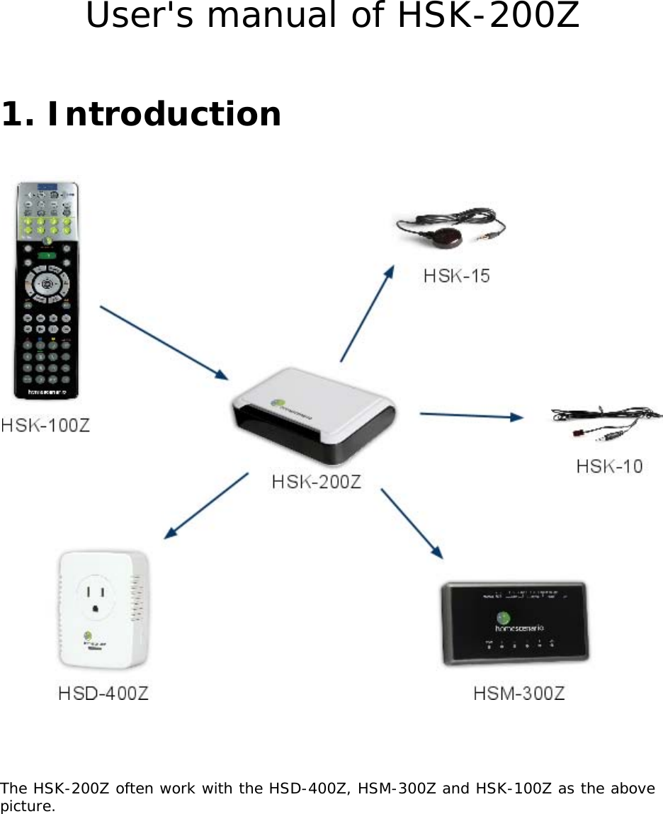
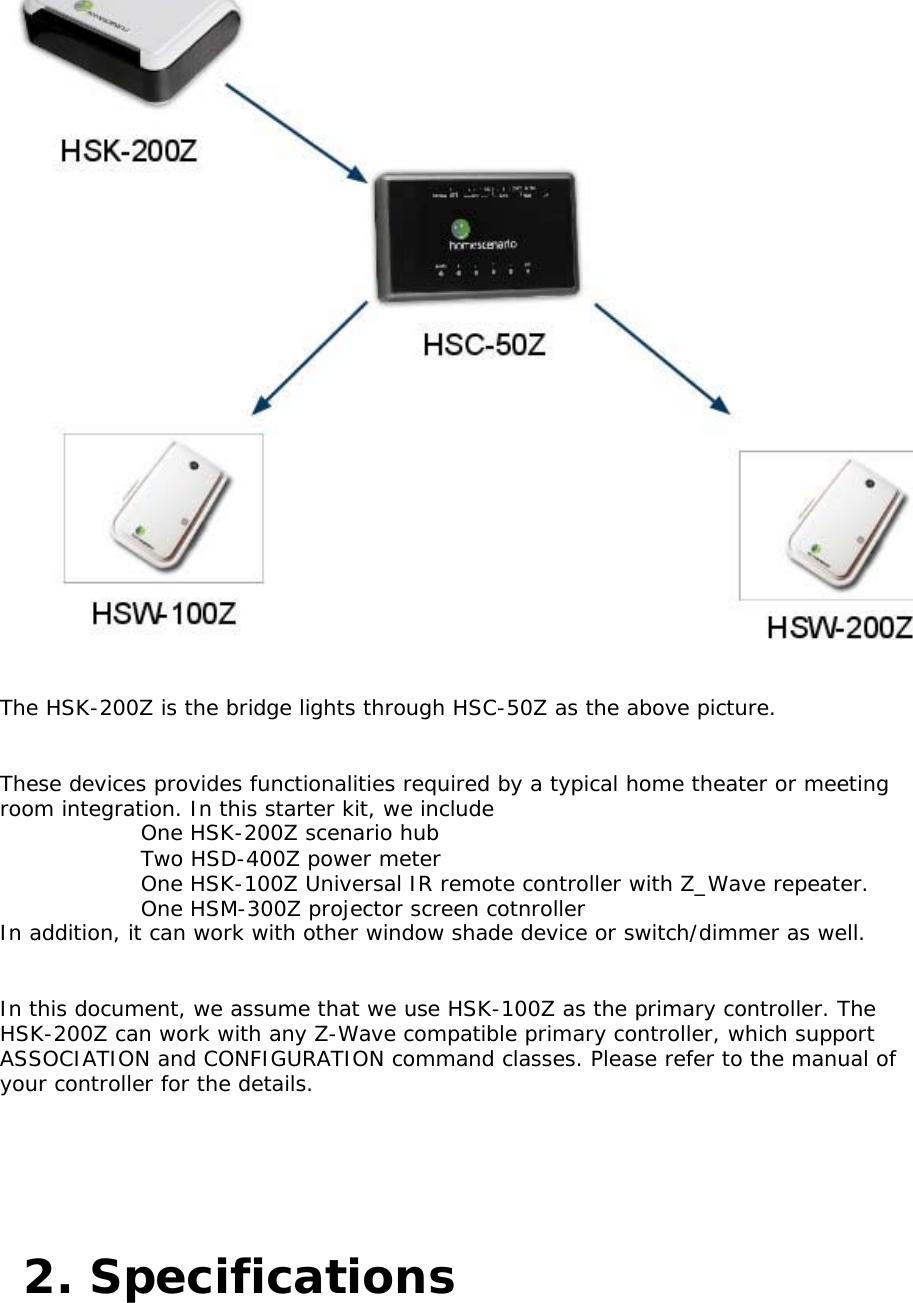
HomeScenario HSK-200Z IR Control Station User Manual User s manual of HSK 200Z

HomeScenario, Inc IR Control Station User s manual of HSK 200Z

User manual

    User's manual of HSK-200Z       1. Introduction        The HSK-200Z often work with the HSD-400Z, HSM-300Z and HSK-100Z as the above picture.
      The HSK-200Z is the bridge lights through HSC-50Z as the above picture.    These devices provides functionalities required by a typical home theater or meeting room integration. In this starter kit, we include      One HSK-200Z scenario hub     Two HSD-400Z power meter     One HSK-100Z Universal IR remote controller with Z_Wave repeater.   One HSM-300Z projector screen cotnroller    In addition, it can work with other window shade device or switch/dimmer as well.    In this document, we assume that we use HSK-100Z as the primary controller. The HSK-200Z can work with any Z-Wave compatible primary controller, which support ASSOCIATION and CONFIGURATION command classes. Please refer to the manual of your controller for the details.   2. Specifications
 3. Supported command class
        The HSK-200Z is AV controller which supports the following command classes      BASIC     Simple AV Control     Version     Manufacturer Specific     Association     Configuration    3.1. BASIC command class    The basic command class is mapped to the scene activation command classes. The value will be mapped into 3.   ofit is the scene ID. If the value is higher than 3, it The basic get will return the last invoked scene.    3.2. Simple AV control    The simple AV control can be used to send IR signals from the internal database.Pleaserefer to the table in the appendix.    3.3. Association    The HSK-200 supports the following groups.
3.4. Configuration     This configuration command classes allow us to fine tune the behaviour ofth eHSK-200Z.      4. Installation    4.1. Inclusion     Put the HSK-100Z into add node mode by using ADD/DEVICE.    Press and release the program button in the bottom of the device by using a needle.Thedevice will broadcast node information and enter learning mode.    The HSK-100Z will add the HSK-200Z from the network and show dolid OK LED. If thereis any error, the Error LED will be turn on instead.
4.3. Install the IR cable        Put the HSK-10 or HSK-15 to plug in the socket of HSK-200Z.
        The LED in front will blink when emit the IR keys successfully.    4.4. Power meter   Add power meter     The HSK200Z support up to three power meter to control three AV devices. Theyareassociated to the following IR codes.      Projector Power (key xxx)     AV power (key xxx)     AVR power (key xxx)    W   e can use the ASSOC key of HSK-500Z to include a power meter. Please use thefollowing table to select the group to associate.
    When the HSK-200Z starts, it will query the associated power meter to get thecurrentsetup.    Auto scene activator    This function enable us to start the scenario when the power meter detect that the associated device is turned on. Usually, the power meter notify the HSK-200Z for its status only. However, it can be used to trigger the scenario as well. For example, if the projector power meter detects the projector is on, the HSK-200 will execute the whole scene 1 if the configuration xxx is non-zero.    In this way, we can use the power button of the projector to start the presentation mode.In addition, the AV power meter can be used to trigger the normal mode and the AVR power meter can be used to start the meeting mode.    This function is disabled by default. In order to start this function, please use the CONF key of HSK-100 to setup the configuration 7&8.    4.5. Device calibration    The HSD-400Z will send SCENE ID 1 to all devices listed in the group 1 when the current exceed the value specified in Configuration 1. In addition, it will send SCENE ID 2 to all evices listed in the group 2.   d However, these values may not be able to detect the current sonsumption of your devices.We may need to determine a good high threshold and a low threshold. We can use the HSK-100Z to adjust these configurations. This is inconvienent since we need to adjust thevalue and verify it. If it does not work, we need to retry again.    The device calibration is a special mode of the HSK-200Z. The procedure is      Use HSK-100Z to add power meter into the HSK-200Z.     Press and hold the program button of the HSK-200Z.     The LED of HSK-200Z will start to blinking.     Press the power button of the device attached to the power meter.   Wait the device is completely on or off.    • Repeat press the power button until the LED stop blinking. The calibrated values will be saved at configuration 1 & 2 of the power meter.    4.6. Add IR keys    The AV starter kit provides 20 IR keys which will be sent in pre-defined scenarios.    4.7. Define key for power off   For most projectors, we need to press power key twice in order to turn off the projector.
   4.8. Curtain     The curtain can be added into the curtain group. Actually, any motor device canbeadded into group 3.    4.9. Projector screen    The projector screen will be lower only in the presentation mode. Please associate theHSM-300Z or other projector motor controller into the group #4.    4.10. Lights    In order to add lights into different scenarios, you can use the following procedure at HSK-100Z.     Press      Press Scene     Press the number 1-8     Press the the device button, which can send a Z-Wave Node Information frame.     Adjust the device to the desired setup.     Press the Scene button    Devices can be added into different scene key by using different values so that we can define the status of devices in different scenes.    However, light defined in the above procedure can be activated from the HSK-100Z only. If you want to use other devices, such as HSK-50 or any scene controller, you need to add a HSC-50Z light scenario controller by using HSK-100Z so that the HSK-200Z can relay the scene activation commands to the HSC-50Z.    5. WARRANTY     This warranty does not cover or apply to:   Limited One (1) Year Warranty    (a) damage to the product due to misuse, mishanding, and abuse, (b) products not used inaccordance with manufacturer's instructions or recommendations, (c) product not assembled or installed according to manufacturer's instructions, (d) normal wear and tear,(e) wearing of the cover do to improper installation of cover and goods (f) damage to the contents of the shelter, (g) permits required due to zoning issues, (h) damage that has occurred during shipping, (i) acts of God. In addition consequential damage and
 incidental damages, such as damage to persons or property are not coverable under this warranty, and you should refer to your homeowner's insurance policy as with any other outside structure. Note: Some states do not allow the exclusion or limitation of certain damages, and in those cases these limitations do not apply.    6. Certification Notice       This device complies with part 15 of the FCC rules. Operation is subjct to the followingtwo conditions:     This devuce may not cause harmful interference    This device must accept any interference that may cause undesired operation.   This equipment has been tested and found to comply with the limits for a class B digital device, pursuant to part 15 of the FCC rules. These limits are designed to provide to provide reasonable protection against harmful interference in a residential installation. This equipment generates, uses and can radiate radio frequency energy and, if not installed and used in accordance with the installation. , May cause harmful interference to radio communication. However, there is no guarantee that interference  Will not occur in a particular installation. if this equipment does cause harmful interference to radio or television reception, which can be determined by turning the equipment off and on, the user is encouraged to try to correct the interference by one or more of the following measures:  -Reorient or relocate the receiving antenna  -Increase the separation between the equipment and receiver  -Connect the equipment into an outlet on a circuit different from that to which the receiver is connected  -Consult the dealer or an experienced radio / TV technician for help   You are cautioned that changes or modifications not expressly approved by the party responsible for compliance could void your authority to operate the equipment.    This device complies with part 15 of the FCC rules. Operation is subject to the following two conditions  (1)            This device may not cause harmful interference and   (2)            This device must accept any interference received, including interference that may cause undesired operation

Navigation menu