Hon Hai Precision Industry B01 WLAN 802.11 b/g/n 1x1 AIOT Module User Manual Manual OEM Installation B01 01
Hon Hai Precision Industry Co., Ltd. WLAN 802.11 b/g/n 1x1 AIOT Module Manual OEM Installation B01 01
Contents
- 1. Manual OEM Installation B01-01
- 2. Manual OEM Installation B01-02
Manual OEM Installation B01-01

CPWB-B450JBKZ PRODUCT SPECIFICATION October 26, 2017
FOXCONN CONFIDENTIAL 1
This preliminary specification is subject to change without notice.
Copyright © 2016 Hon Hai Precision Ind Co., Ltd. All rights reserved
CPWB-B450JBKZ
B01-01
IEEE 802.11 b/g/n 1x1 AIOT Module
Product Specification 1.0
Approved:
Approved:
Prepared by:
________________________
_________________________
_________________________
Zeke Wu
Matt Lin
Ben Ho
Manager
Supervisor
Engineer

CPWB-B450JBKZ PRODUCT SPECIFICATION October 26, 2017
FOXCONN CONFIDENTIAL 2
This preliminary specification is subject to change without notice.
Copyright © 2016 Hon Hai Precision Ind Co., Ltd. All rights reserved
Revision History
Date
Number
Approver
Comments
Dec. 18, 2016
1.0
Ben Ho
Initial Draft
Jan. 04, 2017
1.1
Ben Ho
Adding information of Current consumption and
Sensitivity
Jan. 25, 2017
1.2
Ben Ho
Adding information of Current consumption and
Power consumption
Mar. 31, 2017
1.3
Ben Ho
Adding PCB layout, Placement, PCB specification,
schematic, BOM, RF input and output characteristic
Connector specification and reliability test item
Oct. 26, 2017
1.4
Cathy Kuo
Added FCC & IC Statement
RESTRICTED AND CONFIDENTIAL INFORMATION STATEMENT
CPWB-B450JBKZ PRODUCT SPECIFICATION October 26, 2017
FOXCONN CONFIDENTIAL 3
This preliminary specification is subject to change without notice.
Copyright © 2016 Hon Hai Precision Ind Co., Ltd. All rights reserved
All information contained in this document is the exclusive property of Foxconn Technology Inc. and its
development partners. Any reproduction or disclosure of all or part of this document without the
expressed written consent of Foxconn Technology Inc. is strictly prohibited.

CPWB-B450JBKZ PRODUCT SPECIFICATION October 26, 2017
FOXCONN CONFIDENTIAL 4
This preliminary specification is subject to change without notice.
Copyright © 2016 Hon Hai Precision Ind Co., Ltd. All rights reserved
TABLE OF CONTENTS
Revision History .................................................................................................. 2
Table of Contents ................................................................................................ 4
Chapter 1. Module Overview ............................................................................. 5
1-1 Key Characteristic ......................................................................................................................... 5
1-2 Pin Definition ................................................................................................................................ 5
1-3 PCB Specification .......................................................................................................................... 9
Chapter 2. Electrical and RF Specificaiton ........................................................ 14
2-1 Recommended Operation Rating ............................................................................................... 14
2-2 Digital IO Pin DC Characteristic ................................................................................................... 14
2-3 Analog Performance ................................................................................................................... 15
2-4 Power Consumption ................................................................................................................... 15
2-5 RF input and Output Characteristic ............................................................................................ 15
2-6 WiFi RF Specification – TX ........................................................................................................... 15
2-7 WiFi RF Specification – RX .......................................................................................................... 16
2-8 Antenna Specification Requirements ......................................................................................... 17
Chapter 3. MECHANICAL SPECIFICATION ......................................................... 18
3-1 Module Assembly Dimension ..................................................................................................... 18
Chapter 4. Additional Information ................................................................... 23
4-1 Module Photo ............................................................................................................................. 23
4-2 Label Specification ...................................................................................................................... 23
CPWB-B450JBKZ PRODUCT SPECIFICATION October 26, 2017
FOXCONN CONFIDENTIAL 5
This preliminary specification is subject to change without notice.
Copyright © 2016 Hon Hai Precision Ind Co., Ltd. All rights reserved
CHAPTER 1. MODULE OVERVIEW
The Foxconn B01-01 s a low profile, low power and high performance AIOT module. It is mainly
consisted of Wireless IOT IC RTL8711AM, codec ALC5640 and 8MB flash for developing IOT application
RTL8711AM is a highly integrated single-chip low power 802.11b/g/n Wireless LAN (WLAN)
network controller. It combines an ARM-Cortex M3 MCU, WLAN MAC, a 1T1R capable WLAN based, and
RF in a single chip. It also provides a bunch of configure GPIOs which are configured as digital peripheral
for different applications and control usage. ALC5640 is a high performance, low power, dual I²S
interface audio codec. Asynchronous Sample Rate Converter (ASRC) provides independent and
asynchronous connections to different processors, such as an application processor, baseband processor
or wireless transceiver.
Alc5640 have stereo Class-D Speaker amplifiers provide 1.5W per channel into 8Ω or 2.5W per
channel into 4Ω with a 5V supply, with excellent PSRR and low EMI.
1-1 Key Characteristic
compatible WLAN
72.2Mnps receive and transmit PHY rate using 20MHz bandwidth
150Mnps receive and transmit PHY rate using 40MHz bandwidth
802.11i(WPA,WPA2). Open, shared key, and pair-wise key authentication services
WiFi WPS support
WiFi Direct support
1 set of I2C interface
1 set of log UART with standard baud rate support
I2S with 8/16/24/32/48/96/44.1/88.2KHz sample rate
Mono BTL(Bridge-Tied-Load) Class-D amplifier
CPWB-B450JBKZ PRODUCT SPECIFICATION October 26, 2017
FOXCONN CONFIDENTIAL 6
This preliminary specification is subject to change without notice.
Copyright © 2016 Hon Hai Precision Ind Co., Ltd. All rights reserved
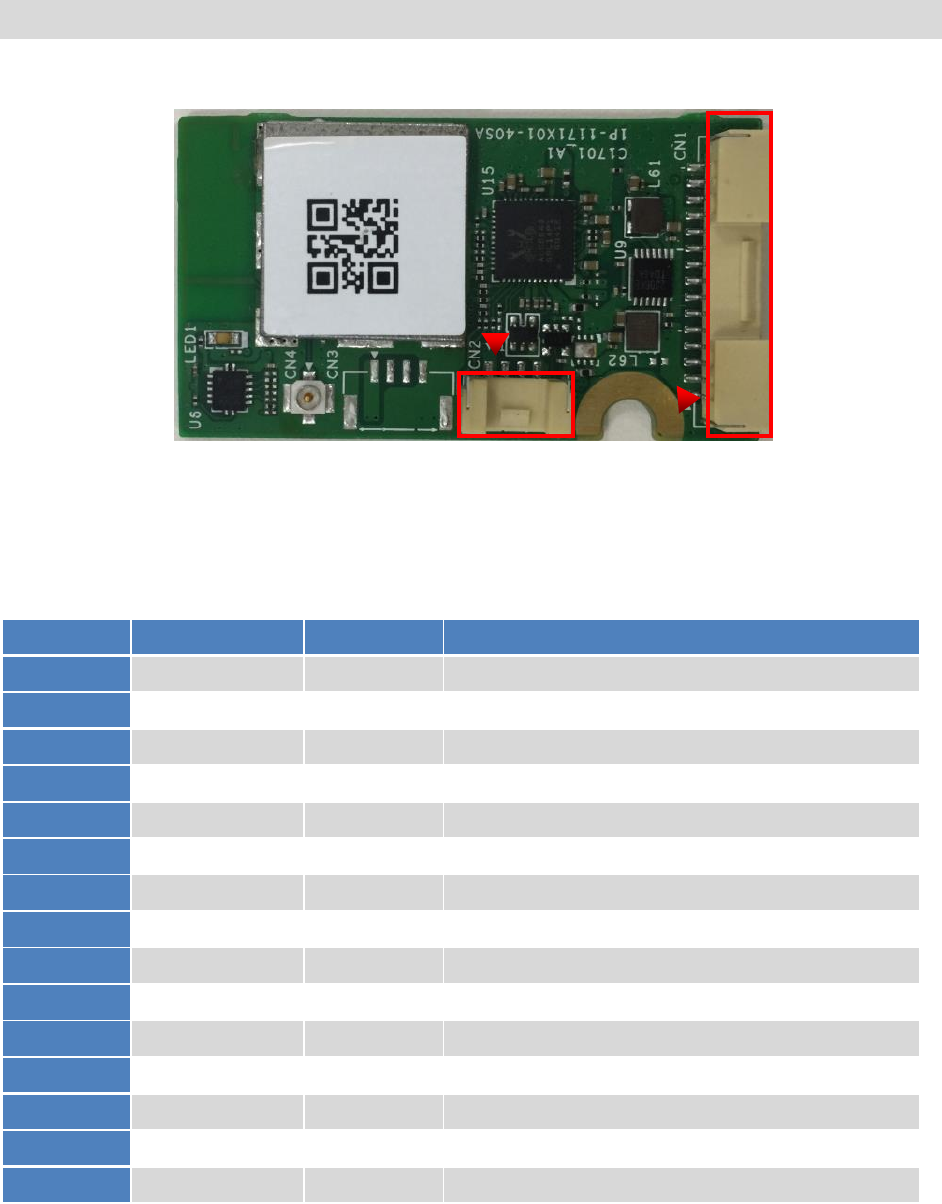
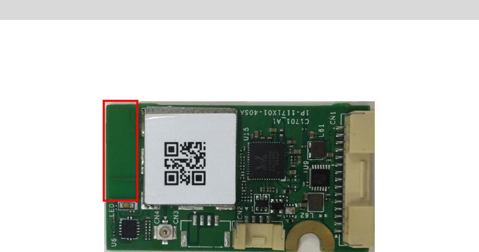
1-2 Pin Definition
Figure 1 Pin Definitions (Module Top View)
Table 1 CN1 Terminal for home appliance Pin Definitions
Pin Number
Symbol Name
Type
Pin Description
1
VCC
POWER
DC 5V
2
VCC
POWER
DC 5V
3
UART0_RTS
I/O
UART RTS (RTL8711AM GPIOA_3)
4
UART0_CTS
I/O
UART CTS (RTL8711AM GPIOA_5)
5
UART0_RX
I/O
UART RX (RTL8711AM GPIOA_6)
6
UART0_TX
I/O
UART TX (RTL8711AM GPIOA_7)
7
CHIP_EN
I
Module enable control active : High(3.3V)
8
NC
NC
NC
9
I2C3_SCL
I/O
I2C Clock (RTL8711AM GPIOB_2)
10
I2C3_SDA
I/O
I2C data (RTL8711AM GPIOB_3)
11
GPIO
I/O
GPIO (RTL8711AM GPIOE_2)
12
GND
GND
Ground
13
SPKOUT_P
O
Speaker amplifier differential positive output
14
SPKOUT_N
O
Speaker amplifier differential negtive output
15
GND
GND
Ground
CN1
CN2

CPWB-B450JBKZ PRODUCT SPECIFICATION October 26, 2017
FOXCONN CONFIDENTIAL 7
This preliminary specification is subject to change without notice.
Copyright © 2016 Hon Hai Precision Ind Co., Ltd. All rights reserved
Table 2 CN2 Service UART terminal Pin Definitions
Pin Number
Symbol Name
Type
Pin Description
1
VCC
POWER
DC 3.3V
2
DEBUG_UART_TX
I/O
Debug UART TX(RTL8711AM GPIOB_0)
3
DEBUG_UART_RX
I/O
Debug UART RX(RTL8711AM GPIOB_1)
4
GND
GND
Ground

CPWB-B450JBKZ PRODUCT SPECIFICATION October 26, 2017
FOXCONN CONFIDENTIAL 8
This preliminary specification is subject to change without notice.
Copyright © 2016 Hon Hai Precision Ind Co., Ltd. All rights reserved
1-3 PCB Specification
Board-maker: Foxconn 宏華精密電子(煙台)有限公司
Material of the board: FR4
Model number: 1P-1173X00-40SB
Board-thickness: 1.0mm (typ)
Product-height: 5.45mm (max)
Tolerance: 0.1mm
Flame class: UL94V-0
CPWB-B450JBKZ PRODUCT SPECIFICATION October 26, 2017
FOXCONN CONFIDENTIAL 9
This preliminary specification is subject to change without notice.
Copyright © 2016 Hon Hai Precision Ind Co., Ltd. All rights reserved
CHAPTER 2. ELECTRICAL AND RF SPECIFICAITON
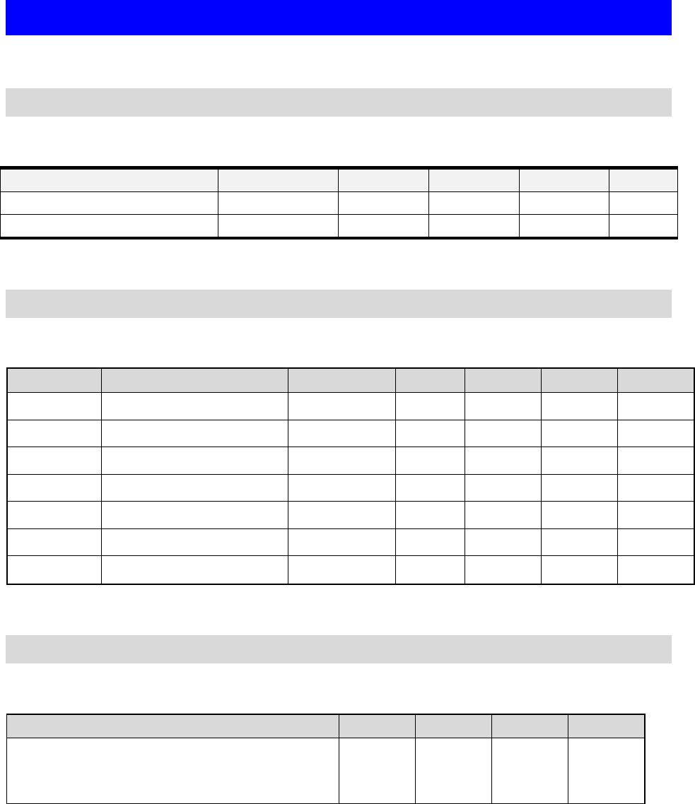
2-1 Recommended Operation Rating
Table 4 Operation Rating
Parameter
Condition
Min
Typ.
Max.
Unit
VCC
3.3V
4.5V
5V
5.5V
V
RF Interface
Zo
50
Ohm
2-2 Digital IO Pin DC Characteristic
Table 5 Typical IO DC Parameter (3.3V)
Symbol
Parameter
Conditions
Min.
Typ.
Max
Units
VIH
Input-High Voltage
LVTTL
2
-
-
V
VIL
Input-Low Voltage
LVTTL
-
-
0.8
V
VOH
Output-High Voltage
LVTTL
2.4
-
-
V
VOL
Output-High Voltage
LVTTL
-
-
0.4
V
VT+
Scmitt-trigger High Level
1.78
1.87
1.97
V
VT+
Scmitt-trigger Low Level
1.36
1.45
1.56
V
IIL
Input-Leakage Current
VIN=3.3v or 0
-10
±1
10
μA
2-3 Analog Performance
Table 6 Analog Performance Characteristics
Parameter
Min.
Typ.
Max
Units
Full Scale Output Voltage
Speaker Amplifiers Output
(SPKVDD=5.0V with 4Ω Load,1% THD+N)
-
2.9
-
Vrms

CPWB-B450JBKZ PRODUCT SPECIFICATION October 26, 2017
FOXCONN CONFIDENTIAL 10
This preliminary specification is subject to change without notice.
Copyright © 2016 Hon Hai Precision Ind Co., Ltd. All rights reserved
2-4 Power Consumption
Table 8 Power Consumption
Description
Typical
Unit
IDLE (Disconnecting to AP)
130
mW
IDLE (Connecting to AP)
280
mW
Maxmimun B mode CCK11M(18dBm) with Speaker play Voice
1125
mW
2G/1T- N mode HT 40MHz MCS 7 (13dBm)
890
mW
2G/1T- N mode HT 20MHz MCS 7 (13dBm)
880
mW
2G/1T- G mode OFDM54M (14dBm)
930
mW
2G/1T- B mode CCK11M (16dBm)
1015
mW
2G/1R- N mode HT 40MHz MCS 7 (-60dBm)
275
mW
2G/1R- N mode HT 20MHz MCS 7 (-60dBm)
275
mW
2G/1R- G mode OFDM54M (-60dBm)
275
mW
2G/1R- B mode CCK11M (-60dBm)
275
mW
2-5 RF input and Output characteristic
˙RF Input and Output characteristic ( Ta=25˚C)
˙Transmitting and receiving frequency:1ch~13ch(center frequency 2412~2472MHz)
˙Wireless system IEEE 802.11b/g/n
2-6 WiFi RF Specification – TX
Table 9 IEEE 802.11 b/g/n TX Output Power(Ave.)
Data Rate
(Mbps)
Modulation
Tx Typical
Power (dBm)
Data Rate
(Mbps)
Modulation
Tx Typical Power
(dBm)
1
DBPSK
16
HT20-MCS0
BPSK
13
2
DQPSK
16
HT20-MCS1
BPSK
13
5.5
CCK
16
HT20-MCS2
QPSK
13
11
CCK
16
HT20-MCS3
QPSK
13
6
OFDM
14
HT20-MCS4
16-QAM
13
9
OFDM
14
HT20-MCS5
16-QAM
13
12
OFDM
14
HT20-MCS6
64-QAM
13
18
OFDM
14
HT20-MCS7
64-QAM
13
CPWB-B450JBKZ PRODUCT SPECIFICATION October 26, 2017
FOXCONN CONFIDENTIAL 11
This preliminary specification is subject to change without notice.
Copyright © 2016 Hon Hai Precision Ind Co., Ltd. All rights reserved
24
OFDM
14
36
OFDM
14
48
OFDM
14
54
OFDM
14
Tolerance:+/-2dBm
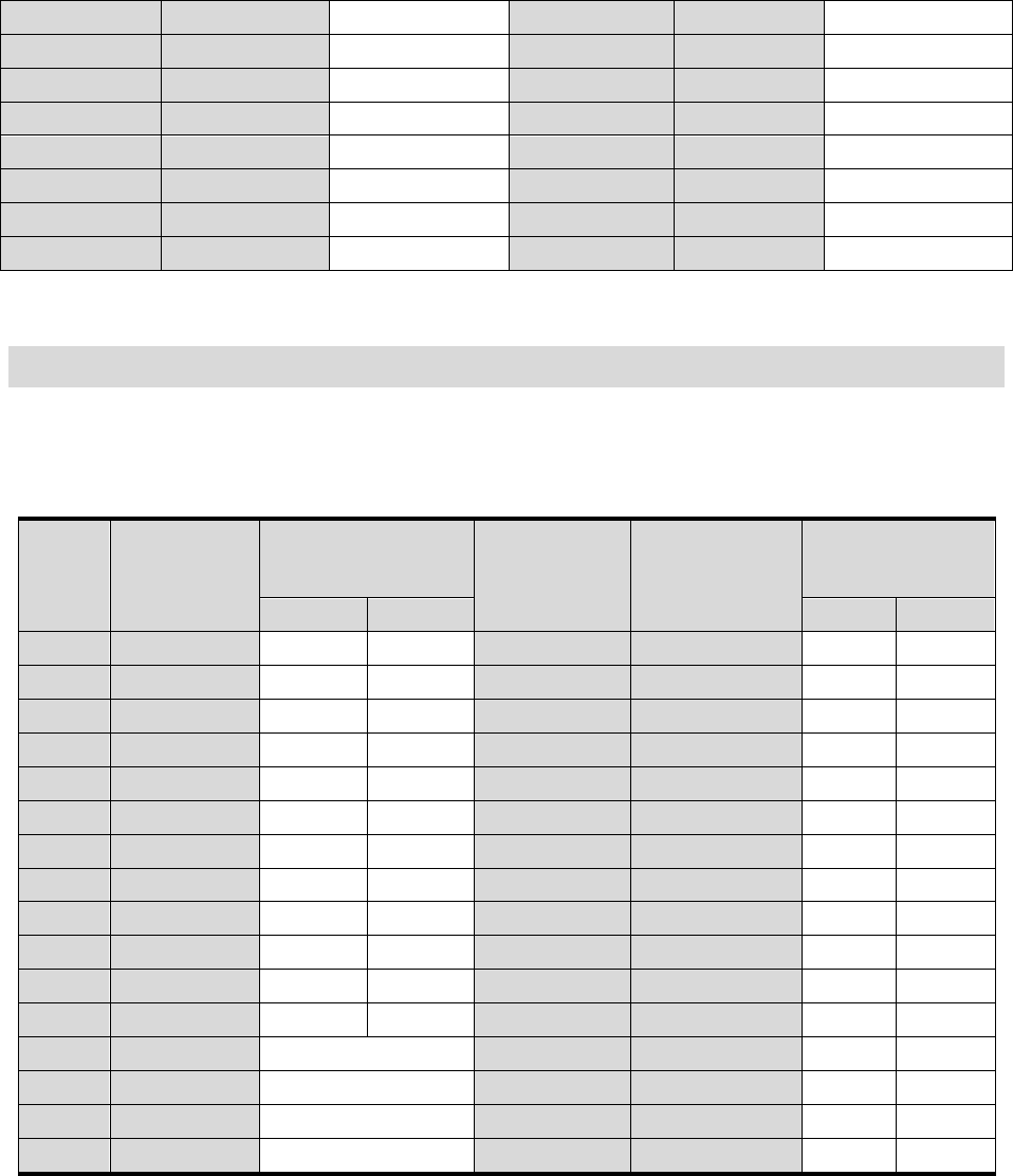
2-7 WiFi RF Specification – RX
Table 10 IEEE 802.11 b/g/n RX Senusitivity
Data
Rate
(Mbps)
Modulation
Rx Sensitivity
(dBm)
Data Rate
(Mbps)
Modulation
Rx Sensitivity
(dBm)
Max.
Typ.
Max.
Typ.
1
DBPSK
-83
-95
HT20-7.22
BPSK
-82
-91
2
DQPSK
-80
-94
HT20-14.44
QPSK
-79
-87.5
5.5
CCK
-79
-90
HT20-21.67
QPSK
-77
-86
11
CCK
-76
-87
HT20-28.89
16-QAM
-74
-82.5
6
OFDM
-85
-92
HT20-43.33
16-QAM
-70
-79.5
9
OFDM
-84
-91
HT20-57.78
64-QAM
-66
-75
12
OFDM
-82
-88.5
HT20-65
64-QAM
-65
-74
18
OFDM
-80
-86.5
HT20-72.22
64-QAM
-64
-72
24
OFDM
-77
-83.5
HT40-15
BPSK
-79
-89
36
OFDM
-73
-80.5
HT40-30
QPSK
-76
-85
48
OFDM
-69
-76
HT40-45
QPSK
-74
-83
54
OFDM
-68
-74.5
HT40-60
16-QAM
-71
-80
HT40-90
16-QAM
-67
-77
HT40-120
64-QAM
-63
-72
HT40-135
64-QAM
-62
-70
HT40-150
64-QAM
-61
-70
CPWB-B450JBKZ PRODUCT SPECIFICATION October 26, 2017
FOXCONN CONFIDENTIAL 12
This preliminary specification is subject to change without notice.
Copyright © 2016 Hon Hai Precision Ind Co., Ltd. All rights reserved
2-8 Antenna Specification Requirements
Nominal antenna port impedance specification is 50 ohms for the Foxconn B01 hardware.
For regulatory requirements, it is assumed that the antenna gain is:
Antenna gain for the 2.4GHz band : 2.0dBi
ANT
CPWB-B450JBKZ PRODUCT SPECIFICATION October 26, 2017
FOXCONN CONFIDENTIAL 13
This preliminary specification is subject to change without notice.
Copyright © 2016 Hon Hai Precision Ind Co., Ltd. All rights reserved
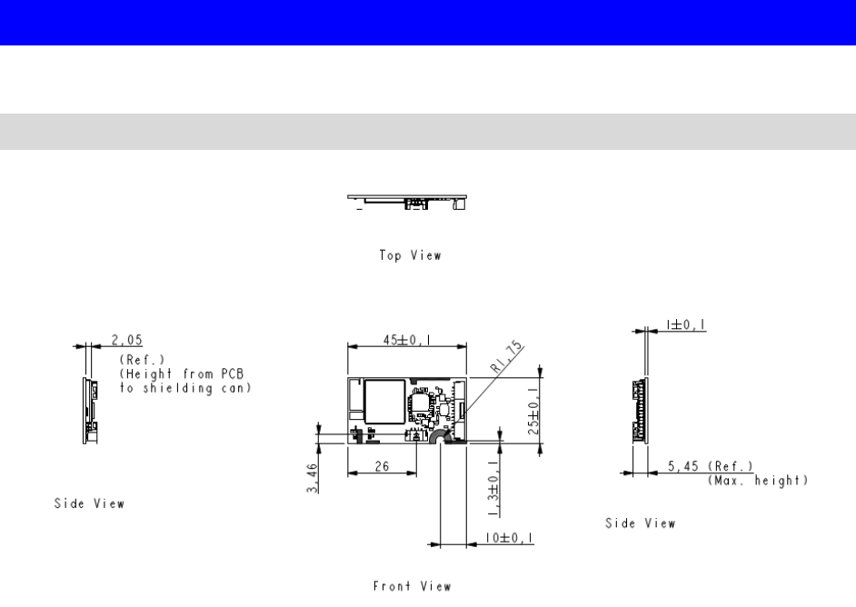
CHAPTER 3. MECHANICAL SPECIFICATION
3-1 Module Assembly Dimension
CPWB-B450JBKZ PRODUCT SPECIFICATION October 26, 2017
FOXCONN CONFIDENTIAL 14
This preliminary specification is subject to change without notice.
Copyright © 2016 Hon Hai Precision Ind Co., Ltd. All rights reserved
CHAPTER 4. ADDITIONAL INFORMATION
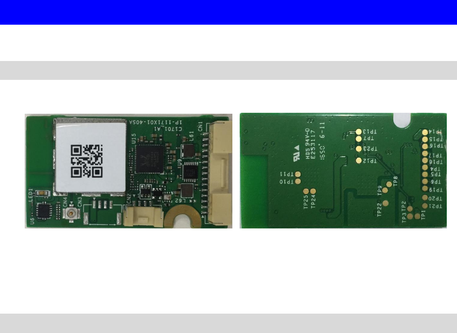
4-1 Module Photo
Figure 2 Top Side Photo Figure3 Bottom Side Photo
4-2 Environment Specifications
˙Operating Conditions (preliminary)
Operation Temperature : -10 ~ 80℃
Relevant Humidity: 5 ~ 95% (non-condensing)
˙Storage Conditions (preliminary)
Non-Operation Temperature : -20 ~ 85℃ (Typ. 25℃)
Relevant Humidity: 5 ~ 95% (non-condensing
CPWB-B450JBKZ PRODUCT SPECIFICATION October 26, 2017
FOXCONN CONFIDENTIAL 15
This preliminary specification is subject to change without notice.
Copyright © 2016 Hon Hai Precision Ind Co., Ltd. All rights reserved
Federal Communication Commission Interference Statement
This device complies with Part 15 of the FCC Rules. Operation is subject to the following two
conditions: (1) This device may not cause harmful interference, and (2) this device must accept
any interference received, including interference that may cause undesired operation.
This equipment has been tested and found to comply with the limits for a Class B digital device,
pursuant to Part 15 of the FCC Rules. These limits are designed to provide reasonable protection
against harmful interference in a residential installation. This equipment generates, uses and
can radiate radio frequency energy and, if not installed and used in accordance with the
instructions, may cause harmful interference to radio communications. However, there is no
guarantee that interference will not occur in a particular installation. If this equipment does
cause harmful interference to radio or television reception, which can be determined by turning
the equipment off and on, the user is encouraged to try to correct the interference by one of
the following measures:
- Reorient or relocate the receiving antenna.
- Increase the separation between the equipment and receiver.
- Connect the equipment into an outlet on a circuit different from that to which the receiver is
connected.
- Consult the dealer or an experienced radio/TV technician for help. FCC Caution: Any changes or
modifications not expressly approved by the party responsible for compliance could void the
user's authority to operate this equipment. This transmitter must not be co-located or
operating in conjunction with any other antenna or transmitter.
Radiation Exposure Statement:
This equipment complies with FCC radiation exposure limits set forth for an uncontrolled
environment. This equipment should be installed and operated with minimum distance 20cm
between the radiator & your body.
This device is intended only for OEM integrators under the following conditions:
1) The antenna must be installed such that 20 cm is maintained between the antenna and users,
and 2) The transmitter module may not be co-located with any other transmitter or antenna.
As long as 2 conditions above are met, further transmitter test will not be required. However,
the OEM integrator is still responsible for testing their end-product for any additional
compliance requirements required with this module installed
IMPORTANT NOTE: In the event that these conditions can not be met (for example certain
laptop configurations or co-location with another transmitter), then the FCC authorization is no
longer considered valid and the FCC ID can not be used on the final product. In these
circumstances, the OEM integrator will be responsible for reevaluating the end product
(including the transmitter) and obtaining a separate FCC authorization.
CPWB-B450JBKZ PRODUCT SPECIFICATION October 26, 2017
FOXCONN CONFIDENTIAL 16
This preliminary specification is subject to change without notice.
Copyright © 2016 Hon Hai Precision Ind Co., Ltd. All rights reserved
End Product Labeling
This transmitter module is authorized only for use in device where the antenna may be installed
such that 20 cm may be maintained between the antenna and users. The final end product must
be labeled in a visible area with the following: “Contains FCC ID: RX3-B01”. The grantee's FCC ID
can be used only when all FCC compliance requirements are met.
Manual Information To the End User
The OEM integrator has to be aware not to provide information to the end user regarding how
to install or remove this RF module in the user’s manual of the end product which integrates this
module. The end user manual shall include all required regulatory information/warning as show
in this manual.

CPWB-B450JBKZ PRODUCT SPECIFICATION October 26, 2017
FOXCONN CONFIDENTIAL 17
This preliminary specification is subject to change without notice.
Copyright © 2016 Hon Hai Precision Ind Co., Ltd. All rights reserved
Canada, Industry Canada (IC) Statement
This Class B digital apparatus complies with Canadian ICES-003.
This device complies with Industry Canada licence-exempt RSS standard(s). Operation is
subject to the following two conditions:
(1) this device may not cause interference, and
(2) this device must accept any interference, including interference that may cause undesired
operation of the device.
RF Radiation Exposure Statement:
This equipment complies with IC radiation exposure limits set forth for an uncontrolled
environment. This equipment should be installed and operated with a minimum distance of 20
centimeters between the radiator and your body.
Required end product labeling:
Any device incorporating this module must include an external, visible, permanent marking
or label which states: “Contains IC: 2878F-B01”
This radio transmitter (identify the device by certification number or model number if Category
II) has been approved by Industry Canada to operate with the antenna types listed below with
the maximum permissible gain indicated. Antenna types not included in this list, having a gain
greater than the maximum gain indicated for that type, are strictly prohibited for use with this
device.
Antenna Type: Printing Peak Gain: 2.0 dBi

CPWB-B450JBKZ PRODUCT SPECIFICATION October 26, 2017
FOXCONN CONFIDENTIAL 18
This preliminary specification is subject to change without notice.
Copyright © 2016 Hon Hai Precision Ind Co., Ltd. All rights reserved
Canada, Industrie Canada (IC ) Déclaration
Cet appareil numérique de classe B est conforme à la norme NMB-003.
Le présent appareil est conforme aux CNR d'Industrie Canada applicables auxappareils radio
exempts de licence.L'exploitation est autorisée aux deux conditions suivantes:
(1) l'appareil ne doit pas produire de brouillage, et
(2) l'utilisateur de l'appareil doit accepter tout brouillage adioélectrique subi, même si le
brouillage est susceptible d'en compromettre le fonctionnement.
Déclaration d'exposition aux radiations:
Cet appareil est conforme aux limites d'exposition aux rayonnements définies pour un
environnement non contrôlé. Cet équipement doit être installé et utilisé à une distance
minimale de 20 centimètres entre le radiateur et votre corps.
Obligation d'étiquetage du produit final:
Tout dispositif intégrant ce module doit comporter un externe, visible, marquage permanent
ou une étiquette qui dit: "Contient IC : 2878F-B01".
Cet émetteur radio ( identifier le dispositif par numéro de certification ou le numéro de modèle ,
si la catégorie II ) a été approuvé par Industrie Canada pour fonctionner avec les types d'antenne
énumérés ci-dessous avec le gain maximal admissible indiqué . types d'antennes non inclus dans
cette liste , ayant un gain supérieur au gain maximum indiqué pour ce type , sont strictement
interdits pour une utilisation avec cet appareil.
Type d'antenne: Printing Pic Gain: 2.0 dBi