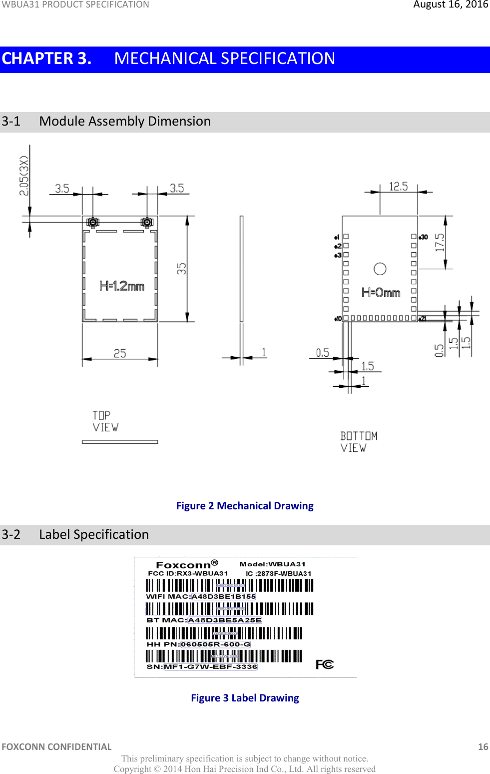
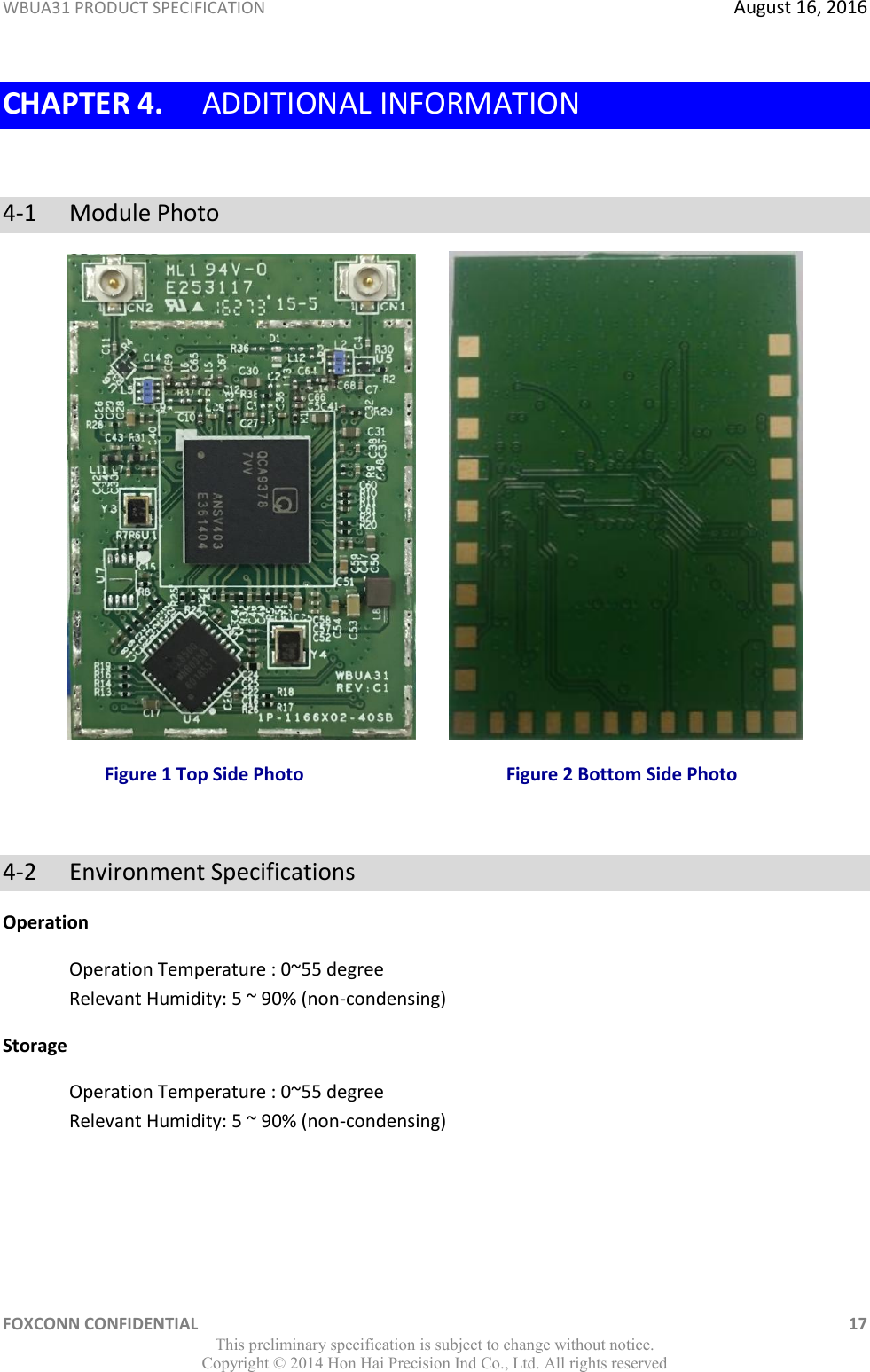
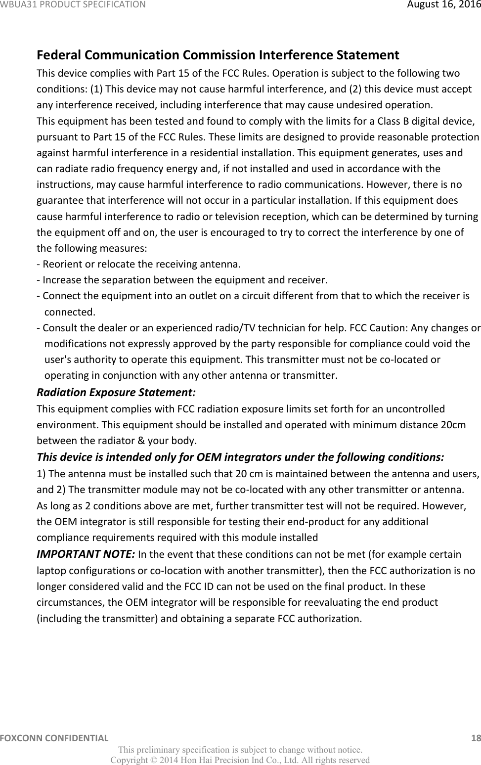
Hon Hai Precision Industry WBUA31 Dual-Band 2x2 802.11ac and BT4.1 Combo Module User Manual

Hon Hai Precision Industry Co., Ltd. Dual-Band 2x2 802.11ac and BT4.1 Combo Module Users Manual

Users Manual

        WBUA31  IEEE 802.11 a/b/g/n/ac 2x2 +BT Combo Module   Product Specification 1.0         Approved: Approved: Prepared by:    ________________________     _________________________    _________________________ Zeke Wu Matt Lin Mark Hsu Manager Supervisor Engineer
WBUA31 PRODUCT SPECIFICATION  August 16, 2016 FOXCONN CONFIDENTIAL    1 This preliminary specification is subject to change without notice. Copyright ©  2014 Hon Hai Precision Ind Co., Ltd. All rights reserved Revision History Date Number Approver Comments Jun. 16, 2016 1.0 Mark Hsu Initial Draft Aug. 16, 2016 1.1 Mark Hsu Update Photos                                RESTRICTED AND CONFIDENTIAL INFORMATION STATEMENT All information contained in this document is the exclusive property of Foxconn Technology Inc. and its development partners. Any reproduction or disclosure of all or part of this document without the expressed written consent of Foxconn Technology Inc. is strictly prohibited.
WBUA31 PRODUCT SPECIFICATION  August 16, 2016 FOXCONN CONFIDENTIAL    2 This preliminary specification is subject to change without notice. Copyright ©  2014 Hon Hai Precision Ind Co., Ltd. All rights reserved  TABLE OF CONTENTS Revision History .................................................................................................. 1 Chapter 1. Module Overview ............................................................................. 4 1-1 Key Characteristic ......................................................................................................................... 4 1-2 LGA Pin Definition ......................................................................................................................... 5 Chapter 2. Electrical and RF Specificaiton .......................................................... 7 2-1  Recommended Operation Rating ......................................................................................... 7 2-2  Power Consumption.............................................................................................................. 7 2-3  WiFi RF Specification – TX ..................................................................................................... 8 2-4  WiFi RF Specification – RX ................................................................................................... 10 2-5 Bluetooth RF Specification .......................................................................................................... 12 2-6 Bluetooth Low Energy RF Specification ...................................................................................... 14 2-7 Antenna Specification Requirment ............................................................................................. 15 Chapter 3. MECHANICAL SPECIFICATION ......................................................... 16 3-1  Module Assembly Dimension ............................................................................................. 16 3-2  Label Specification .............................................................................................................. 16 Chapter 4. Additional Information ................................................................... 17 4-1 Module Photo ............................................................................................................................. 17 4-2 Environment Specifications ........................................................................................................ 17
WBUA31 PRODUCT SPECIFICATION  August 16, 2016 FOXCONN CONFIDENTIAL    3 This preliminary specification is subject to change without notice. Copyright ©  2014 Hon Hai Precision Ind Co., Ltd. All rights reserved  Figures: Figure 1 Pin Definitions(Module Bottom View) ............................................................................................................. 5 Figure 2 Mechanical Drawing ...................................................................................................................................... 16 Figure 3 Label Drawing ................................................................................................................................................ 16 Figure 4 Top Side Photo ............................................................................................................................................... 17 Figure 5 Bottom Side Photo ......................................................................................................................................... 17 Tables Table 1 Pin Definitions ................................................................................................................................................... 5 Table 2 Operation Rating ............................................................................................................................................... 7 Table 3 Power Consumption.......................................................................................................................................... 7 Table 4 IEEE 802.11 b/g/n TX Output Power (WLAN0 & WLAN1) ................................................................................. 8 Table 5 IEEE 802.11 a/n/ac TX Output Power  (WLAN0 & WLAN1) ............................................................................... 9 Table 6 IEEE 802.11 b/g/n/ac Rx sensitivity (WLAN0 & WLAN1) ................................................................................. 10 Table 7 IEEE 802.11 a/n/ac Rx sensitivity (WLAN0 & WLAN1) .................................................................................... 11
WBUA31 PRODUCT SPECIFICATION  August 16, 2016 FOXCONN CONFIDENTIAL    4 This preliminary specification is subject to change without notice. Copyright ©  2014 Hon Hai Precision Ind Co., Ltd. All rights reserved  CHAPTER 1. MODULE OVERVIEW The Foxconn WBUA31 WLAN/BT module contains the Qualcomm Atheros QCA9378 single-chip which is a highly integrated IEEE 802.11 a/b/g/n/ac and Bluetooth 4.1 +HS. It provides a small form-factor solution with minimal external components to drive down cost for  1-1  Key Characteristic  Highly integrated wireless local area network (WLAN) system-on-chip(SoC) for 5GHz 802.11ac, or 2.4/5 GHz 802.11n WLAN applications.  Bluetooth 4.1 + HS, BLE, ANT+ and be backwards compatible with BT 1.X, 2.X+Enhanced Datarate.  Concurrent Bluetooth and WLAN operation.  20/40 MHz at 2.4GHz and 20/40/80MHz MHz at 5 GHz.  Reverse direction grant data flow and frame aggregation  Security : WEP ,WPA ,WPA2, TKIP, AES, CKIP  QoS-WMM, WMM-PS, WMM-SA  A full-speed USB 2.0-compliant interface for WLAN and Bluetooth  Bluetooth SmartAudio® technology improves voice and music quality to headsets  Bluetooth low-power (BLE) support  Bluetooth packet loss concealment(PLC)
WBUA31 PRODUCT SPECIFICATION  August 16, 2016 FOXCONN CONFIDENTIAL    5 This preliminary specification is subject to change without notice. Copyright ©  2014 Hon Hai Precision Ind Co., Ltd. All rights reserved  1-2  LGA Pin Definition  Figure 1 Pin Definitions (Module Bottom View) Table 1 Pin Definitions Pin Number Symbol Name Type Pin Description 1 GND GND Ground 2 GND GND Ground 3 GND GND Ground 4 VDD3_3 Power 3.3V 5 GND GND Ground 6 GND GND Ground 7 BT_Host_Wake O Host wake up 8 BT_DEV_WAKE I Bluetooth device wake up 9 NC NC NC 10 GND GND Ground 11 USB_D- I/O USB 2.0 D- 12 USB_D+ Power USB 2.0 D+ 13 GND GND Ground 14 GND GND Ground 15 BT_REG_ON I Power-up/Power-Down/Reset Control Signal 1 2 3 10 11 12 21 30 29
WBUA31 PRODUCT SPECIFICATION  August 16, 2016 FOXCONN CONFIDENTIAL    6 This preliminary specification is subject to change without notice. Copyright ©  2014 Hon Hai Precision Ind Co., Ltd. All rights reserved 16 WL_REG_ON  I Power-up/Power-Down/Reset Control Signal 17 WLAN_WOW O Host wake up 18 NC NC NC 19 GND GND Ground 20 VDD3_3 Power 3.3V 21 GND GND Ground 22 GND GND Ground 23 GND GND Ground 24 GND GND Ground 25 GND GND Ground 26 GND GND Ground 27 GND GND Ground 28 GND GND Ground 29 GND GND Ground 30 GND GND Ground
WBUA31 PRODUCT SPECIFICATION  August 16, 2016 FOXCONN CONFIDENTIAL    7 This preliminary specification is subject to change without notice. Copyright ©  2014 Hon Hai Precision Ind Co., Ltd. All rights reserved  CHAPTER 2. ELECTRICAL AND RF SPECIFICAITON  2-1   Recommended Operation Rating Table 2 Operation Rating Parameter Condition Min Typ. Max. Unit VDD3_3 3.3V 3.3V 3.3V 3.6V V RF Interface Zo  50  Ohm 2-2   Power Consumption Power consumption is measured using current probe loop on the Power rails of the USB interface (Pins). Table 3 Power Consumption Description Typical Unit IDLE 150 mA 2G/2T- N mode HT 40MHz MCS 7(14dBm) 450 mA 2G/2T- N mode HT 20MHz MCS 7(14dBm) 510 mA 2G/1T- G mode OFDM54M(15dBm) 320 mA 2G/1T- B mode CCK11M (15dBm) 350 mA 5G/2T- AC mode HT 80MHz MCS 9(7dBm) 460 mA 5G/2T- N mode HT 40MHz MCS 7(10dBm) 560 mA 5G/2T- N mode HT 20MHz MCS 7(11dBm) 490 mA 5G/1T- A mode OFDM54M(12dBm) 300 mA 2G/2R- N mode HT 40MHz MCS 7 (-60dBm) 128 mA 2G/2R- N mode HT 20MHz MCS 7 (-60dBm) 125 mA 2G/1R- G mode OFDM54M (-60dBm) 127 mA 2G/1R- B mode CCK11M (-60dBm) 126 mA 5G/1R- AC mode HT 80MHz MCS 9(-60dBm) 157 mA 5G/2R- N mode HT 40MHz MCS 7(-60dBm) 150 mA 5G/2R- N mode HT 20MHz MCS 7(-60dBm) 147 mA 5G/1R- A mode OFDM54M(-60dBm) 147 mA
WBUA31 PRODUCT SPECIFICATION  August 16, 2016 FOXCONN CONFIDENTIAL    8 This preliminary specification is subject to change without notice. Copyright ©  2014 Hon Hai Precision Ind Co., Ltd. All rights reserved  2-3   WiFi RF Specification – TX  Table 4 IEEE 802.11 b/g/n TX Output Power (WLAN0&WLAN1) Data Rate (Mbps) Modulation Tx Typical Power (dBm) Data Rate (Mbps) Modulation Tx Typical Power (dBm) 1 DBPSK 15 HT20-MCS0 BPSK 14 2 DQPSK 15 HT20-MCS1 BPSK 14 5.5 CCK 15 HT20-MCS2 QPSK 14 11 CCK 15 HT20-MCS3 QPSK 14 6 OFDM 15 HT20-MCS4 16-QAM 14 9 OFDM 15 HT20-MCS5 16-QAM 14 12 OFDM 15 HT20-MCS6 64-QAM 14 18 OFDM 15 HT20-MCS7 64-QAM 14 24 OFDM 15 HT40-MCS0 BPSK 14 36 OFDM 15 HT40-MCS1 QPSK 14 48 OFDM 15 HT40-MCS2 QPSK 14 54 OFDM 15 HT40-MCS3 16-QAM 14    HT40-MCS4 16-QAM 14    HT40-MCS5 64-QAM 14    HT40-MCS6 64-QAM 14    HT40-MCS7 64-QAM 14 Tolerance:+/- 2dBm
WBUA31 PRODUCT SPECIFICATION  August 16, 2016 FOXCONN CONFIDENTIAL    9 This preliminary specification is subject to change without notice. Copyright ©  2014 Hon Hai Precision Ind Co., Ltd. All rights reserved  Table 5 IEEE 802.11 a/n/ac TX Output Power(WLAN0&WLAN1) Data Rate (Mbps) Modulation Tx Typical Power (dBm) Data Rate (Mbps) Modulation Tx Typical Power (dBm) 6 OFDM 10 HT20-MCS0 BPSK 11 9 OFDM 10 HT20-MCS1 BPSK 11 12 OFDM 10 HT20-MCS2 QPSK 11 18 OFDM 10 HT20-MCS3 QPSK 11 24 OFDM 10 HT20-MCS4 16-QAM 11 36 OFDM 10 HT20-MCS5 16-QAM 11 48 OFDM 10 HT20-MCS6 64-QAM 11 54 OFDM 10 HT20-MCS7 64-QAM 11    HT40-MCS0 BPSK 10    HT40-MCS1 QPSK 10    HT40-MCS2 QPSK 10    HT40-MCS3 16-QAM 10    HT40-MCS4 16-QAM 10    HT40-MCS5 64-QAM 10    HT40-MCS6 64-QAM 10    HT40-MCS7 64-QAM 10    HT80_MCS0 BPSK 7    HT80_MCS1 QPSK 7    HT80_MCS2 QPSK 7    HT80_MCS3 16-QAM 7    HT80_MCS4 16-QAM 7    HT80_MCS5 64-QAM 7    HT80_MCS6 64-QAM 7    HT80_MCS7 64-QAM 7    HT80_MCS8 256-QAM 7    HT80_MCS9 256-QAM 7       Tolerance:+/- 2dBm
WBUA31 PRODUCT SPECIFICATION  August 16, 2016 FOXCONN CONFIDENTIAL    10 This preliminary specification is subject to change without notice. Copyright ©  2014 Hon Hai Precision Ind Co., Ltd. All rights reserved  2-4   WiFi RF Specification – RX  Table 6 IEEE 802.11 b/g/n RX Sensitivity (WLAN0&WLAN1) Data Rate (Mbps) Modulation Rx Sensitivity (dBm) Data Rate (Mbps) Modulation Rx Sensitivity (dBm) Max. Typ. Max. Typ. 1 DBPSK -83 -94 HT20-7.22 BPSK -82 -89.5 2 DQPSK -80 -93.5 HT20-14.44 QPSK -79 -87.5 5.5 CCK -83 -91 HT20-21.67 QPSK -77 -85.5 11 CCK -80 -88.5 HT20-28.89 16-QAM -74 -82.5 6 OFDM -85 -90 HT20-43.33 16-QAM -70 -80.5 9 OFDM -84 -89.5 HT20-57.78 64-QAM -66 -76 12 OFDM -82 -89 HT20-65 64-QAM -65 -75 18 OFDM -80 -86 HT20-72.22 64-QAM -64 -73.5 24 OFDM -77 -83.5 HT40-15 BPSK -79 -89.5 36 OFDM -73 -80 HT40-30 QPSK -76 -86.5 48 OFDM -69 -76 HT40-45 QPSK -74 -84 54 OFDM -68 -74.5 HT40-60 16-QAM -71 -81    HT40-90 16-QAM -67 -78.5    HT40-120 64-QAM -63 -74    HT40-135 64-QAM -62 -71.5    HT40-150 64-QAM -61 -68
WBUA31 PRODUCT SPECIFICATION  August 16, 2016 FOXCONN CONFIDENTIAL    11 This preliminary specification is subject to change without notice. Copyright ©  2014 Hon Hai Precision Ind Co., Ltd. All rights reserved  Table 7 IEEE 802.11 a/n/ac RX Sensitivity (WLAN0&WLAN1)) Data Rate (Mbps) Modulation Rx Sensitivity (dBm) Data Rate (Mbps) Modulation Rx Sensitivity (dBm) Max. Typ. Max. Typ. 6 OFDM -85 -88 HT20-7.22 BPSK -82 -88 9 OFDM -84 -88 HT20-14.44 QPSK -79 -87 12 OFDM -82 -86.5 HT20-21.67 QPSK -77 -85 18 OFDM -80 -84.5 HT20-28.89 16-QAM -74 -82 24 OFDM -77 -82 HT20-43.33 16-QAM -70 -79 36 OFDM -73 -78.5 HT20-57.78 64-QAM -66 -75 48 OFDM -69 -74.5 HT20-65 64-QAM -65 -73 54 OFDM -68 -73 HT20-72.22 64-QAM -64 -72     HT40-15 BPSK -79 -85     HT40-30 QPSK -76 -84     HT40-45 QPSK -74 -82     HT40-60 16-QAM -71 -79     HT40-90 16-QAM -67 -75.5     HT40-120 64-QAM -63 -71.5     HT40-135 64-QAM -62 -70     HT40-150 64-QAM -61 -68.5     HT80_MCS0 BPSK -76 -87     HT80_MCS1 QPSK -73 -83     HT80_MCS2 QPSK -71 -81     HT80_MCS3 16-QAM -68 -78     HT80_MCS4 16-QAM -64 -75     HT80_MCS5 64-QAM -60 -70     HT80_MCS6 64-QAM -59 -69     HT80_MCS7 64-QAM -58 -67     HT80_MCS8 256-QAM -53 -62     HT80_MCS9 256-QAM -51 -60
WBUA31 PRODUCT SPECIFICATION  August 16, 2016 FOXCONN CONFIDENTIAL    12 This preliminary specification is subject to change without notice. Copyright ©  2014 Hon Hai Precision Ind Co., Ltd. All rights reserved 2-5  Bluetooth RF Specification  Parameter Condition Min. Typ. Max. Unit Basic Data Rate – Transmit Performance RF Transmit Power (TRM01) 4 8 12 dBm Power Density (TRM02) Per 100kHz ≤20 dBm Power Control (TRM03) 2≤ step size ≤ 8 dB TX Output Spectrum –  Freq. Range (TRM04) F(low)- CH0 > 2400 MHz F(high)-CH78 < 2483.5 TX Output Spectrum – 20dB BW (TRM05) ∣fH-fL∣< 1000 MHz TX Output Spectrum –  Adjacent Channel Power (TRM06) ∣f-f0∣= 2MHz ≤ -20 dBm ∣f-f0∣≥ 3MHz ≤ -40 TX Output Spectrum –  Out of Band Spurious Emission 30MHz – 1GHz ≤ -36 dBm 1GHz -12.75GHz    ≤ -30 5.15GHz -5.35GHz ≤ -47 5.725GHz-5.825GHz ≤ -47 Modulation Characteristic (TRM07) Delta f1 avg 140 ≤ ∆f1avg≤ 175 kHz Delta f2 max ≥ 115 at 99.9% Delta f2 avg/Delta f1 avg     ≥ 0.8 Initial Carrier Frequency Tolerance (TRM08) ≤± 75 kHz Carrier Frequency Drift (TRM09) DH1 ≤± 25 kHz DH3 ≤± 40 DH5 ≤± 40 Maximum Drift Rate (TRM09) 20 kHz/50 us  Enhanced Data Rate – Transmit Performance RF Transmit Power π/4 DQPSK 1 5 9 dBm 8DPSK 1 5 9 Relative Transmit Power (TRM10) All pairs (PGFSK-4 dB)<PDPSK<(PGFSK+1 dB) Carrier Frequency Stability (TRM11) All packets -75 ≤ wi≤ 75 kHz All blocks -75 ≤ (w0+wi) ≤ 75 All blocks -10 ≤ w0 ≤ 10 Modulation Accuracy –  RMS DEVM (TRM11) π/4 DQPSK ≤ 20 % 8DPSK ≤ 13 Modulation Accuracy –  Peak DEVM (TRM11) π/4 DQPSK ≤ 35 8DPSK ≤ 25 Modulation Accuracy –  99% DEVM (TRM11) π/4 DQPSK ≤ 30 8DPSK ≤ 20 EDR Differential Phase Emissions (TRM12) ≥ 99 % In-band Spurious Emission (TRM13) ∣f-f0∣= 1MHz ≤ -26 dB ∣f-f0∣= 2MHz ≤ -20 dBm ∣f-f0∣≥ 3MHz ≤ -40
WBUA31 PRODUCT SPECIFICATION  August 16, 2016 FOXCONN CONFIDENTIAL    13 This preliminary specification is subject to change without notice. Copyright ©  2014 Hon Hai Precision Ind Co., Ltd. All rights reserved  TX Output Spectrum –  Out of Band Spurious Emission 30MHz – 1GHz ≤ -36 dBm 1GHz -12.75GHz ≤ -30 5.15GHz -5.35GHz ≤ -47 5.725GHz-5.825GHz ≤ -47 Enhanced power control (TRM14) Step Size 2 ≤ Step Size ≤ 8 dB  Difference. Btw. GFSK, π/4 DQPSK,&8DPSK ≤ 10 Basic Data Rate – Receiver Performance Sensitivity at 0.1% BER (RCV01-02) ≤ -81 dBm C/I Co-Channel interference (RCV03) ≤ 11 dB C/I Adjacent CH interference (RCV03) ∣f-f0∣= 1MHz ≤ 0 ∣f-f0∣= 2MHz ≤ -30 ∣f-f0∣≥ 3MHz ≤ -40 C/I Image CH interference (RCV03) C/Iimage ≤ -9 C/Iimage±1MHz ≤ -20 Out of band Blocking (RCV04) 30MHz – 2000 MHz -10 dBm 2003MHz – 2399MHz -27 2484MHz –  2997MHz -27 3000MHz –  12750MHz -10 Intermodulation Performance at ≤ 0.1% BER (RCV05) -64 dBm Maximum input power level  ≥ -20 dBm Spurious Emission 30MHz – 12.75GHz ≤ -57 dBm Enhanced Data Rate – Receiver Performance Sensitivity at 0.1% BER (RCV07) π/4 DQPSK ≤ -85 dBm 8DPSK ≤ -77 EDR BER Floor Performance at ≤ 0.0007% BER (RCV08) -60 dBm C/I Co-Channel interference (RCV09) π/4 DQPSK ≤ +13 dB 8DPSK ≤ +21 C/I Adjacent Channel C/I ∣f-f0∣= 1MHz (RCV09) π/4 DQPSK ≤ 0 8DPSK ≤ +5 C/I Adjacent Channel C/I ∣f-f0∣= 2MHz (RCV09) π/4 DQPSK ≤ -30 8DPSK ≤ -25 C/I Adjacent Channel C/I ∣f-f0∣≥3MHz (RCV09) π/4 DQPSK ≤ -40 8DPSK ≤ -33 C/I Image Channel C/Iimage (RCV09) π/4 DQPSK ≤ -7 8DPSK ≤ 0 C/I Image Channel C/Iimage±1MHz  (RCV09) π/4 DQPSK ≤ -20 8DPSK ≤ -13 Maximum input power level (RCV10) ≥ -20 dBm Spurious Emission 30MHz – 12.75GHz ≤ -57 Pass
WBUA31 PRODUCT SPECIFICATION  August 16, 2016 FOXCONN CONFIDENTIAL    14 This preliminary specification is subject to change without notice. Copyright ©  2014 Hon Hai Precision Ind Co., Ltd. All rights reserved 2-6  Bluetooth Low Energy RF Specification  Parameter Condition Min. Typ. Max. Unit Transmit Performance RF Transmit Power (TRM-LE01,02) 0 4 8 dBm In-Band Emission (TRM-LE03,04) ∣f-f0∣= 2MHz ≤ -20 dBm ∣f-f0∣≥ 3MHz ≤ -30 TX Output Spectrum –  Out of Band Spurious Emission 30MHz – 1GHz ≤ -36 dBm 1GHz -12.75GHz    ≤ -30 5.15GHz -5.35GHz ≤ -47 5.725GHz-5.825GHz ≤ -47 Modulation Characteristic (TRM-LE05) Delta f1 avg 225 ≤ ∆f1avg≤ 275 kHz Delta f2 max ≥ 185 at 99.9% Delta f2 avg/Delta f1 avg     ≥ 0.8 Carrier Frequency Drift (TRM-LE06,07) Center frequency ≤± 150 kHz During any packet ≤± 50 Maximum Drift Rate (TRM-LE06,07) 20 Hz/50 us  Receiver Performance Sensitivity at 30.8% PER(0.1%BER) (RCV-LE01,02) ≤ -81 dBm C/I Co-Channel interference (RCV-LE03) Co-channel ≤ 21 dB C/I Adjacent CH interference (RCV-LE03) ∣f-f0∣= 1MHz ≤ 15 ∣f-f0∣= 2MHz ≤ -17 ∣f-f0∣≥ 3MHz ≤ -27 C/I Image CH interference (RCV-LE03) C/Iimage ≤ -9 C/Iimage±1MHz ≤ -15 Out of band Blocking (RCV-LE04) 30MHz – 2000 MHz -30 dBm 2003MHz – 2399MHz -35 2484MHz –  2997MHz -35 3000MHz –  12750MHz -30 Intermodulation Performance at ≤30.8% (≤ 0.1% BER) (RCV-LE05) -64 dBm Maximum input power level (RCV-LE06) ≥ -10 dBm PER Report Integrity 50% ≤ PER ≤ 65.4% (RCV-LE07) -30 dBm Spurious Emission 30MHz – 12.75GHz ≤ -57 dBm
WBUA31 PRODUCT SPECIFICATION  August 16, 2016 FOXCONN CONFIDENTIAL    15 This preliminary specification is subject to change without notice. Copyright ©  2014 Hon Hai Precision Ind Co., Ltd. All rights reserved 2-7  Antenna Specification Requirement Nominal antenna port impedance specification is 50 ohms for the Foxconn WBUB15. For regulatory requirements, it is assumed that the antenna gain is: For WLAN0 & WLAN1(WLAN): WLAN0 Antenna gain for the 2.4GHz band : 2.46 dBi Antenna gain for the 5GHz band : 4.57 dBi WLAN1 Antenna gain for the 2.4GHz band : 3.22 dBi Antenna gain for the 5GHz band : 5.35 dBi For Bluetooth:  Antenna gain for the 2.4GHz band : 0.09 dBi     WLAN1 WLAN0 & BT
WBUA31 PRODUCT SPECIFICATION  August 16, 2016 FOXCONN CONFIDENTIAL    16 This preliminary specification is subject to change without notice. Copyright ©  2014 Hon Hai Precision Ind Co., Ltd. All rights reserved CHAPTER 3. MECHANICAL SPECIFICATION  3-1   Module Assembly Dimension   Figure 2 Mechanical Drawing 3-2   Label Specification   Figure 3 Label Drawing
WBUA31 PRODUCT SPECIFICATION  August 16, 2016 FOXCONN CONFIDENTIAL    17 This preliminary specification is subject to change without notice. Copyright ©  2014 Hon Hai Precision Ind Co., Ltd. All rights reserved CHAPTER 4. ADDITIONAL INFORMATION  4-1  Module Photo         Figure 1 Top Side Photo                                            Figure 2 Bottom Side Photo  4-2  Environment Specifications Operation Operation Temperature : 0~55 degree Relevant Humidity: 5 ~ 90% (non-condensing) Storage Operation Temperature : 0~55 degree Relevant Humidity: 5 ~ 90% (non-condensing)
WBUA31 PRODUCT SPECIFICATION  August 16, 2016 FOXCONN CONFIDENTIAL    18 This preliminary specification is subject to change without notice. Copyright ©  2014 Hon Hai Precision Ind Co., Ltd. All rights reserved Federal Communication Commission Interference Statement  This device complies with Part 15 of the FCC Rules. Operation is subject to the following two conditions: (1) This device may not cause harmful interference, and (2) this device must accept any interference received, including interference that may cause undesired operation.  This equipment has been tested and found to comply with the limits for a Class B digital device, pursuant to Part 15 of the FCC Rules. These limits are designed to provide reasonable protection against harmful interference in a residential installation. This equipment generates, uses and can radiate radio frequency energy and, if not installed and used in accordance with the instructions, may cause harmful interference to radio communications. However, there is no guarantee that interference will not occur in a particular installation. If this equipment does cause harmful interference to radio or television reception, which can be determined by turning the equipment off and on, the user is encouraged to try to correct the interference by one of the following measures:  - Reorient or relocate the receiving antenna.  - Increase the separation between the equipment and receiver.  - Connect the equipment into an outlet on a circuit different from that to which the receiver is     connected.  - Consult the dealer or an experienced radio/TV technician for help. FCC Caution: Any changes or     modifications not expressly approved by the party responsible for compliance could void the     user's authority to operate this equipment. This transmitter must not be co-located or     operating in conjunction with any other antenna or transmitter.  Radiation Exposure Statement:  This equipment complies with FCC radiation exposure limits set forth for an uncontrolled environment. This equipment should be installed and operated with minimum distance 20cm between the radiator & your body. This device is intended only for OEM integrators under the following conditions:  1) The antenna must be installed such that 20 cm is maintained between the antenna and users, and 2) The transmitter module may not be co-located with any other transmitter or antenna.  As long as 2 conditions above are met, further transmitter test will not be required. However, the OEM integrator is still responsible for testing their end-product for any additional compliance requirements required with this module installed IMPORTANT NOTE: In the event that these conditions can not be met (for example certain laptop configurations or co-location with another transmitter), then the FCC authorization is no longer considered valid and the FCC ID can not be used on the final product. In these circumstances, the OEM integrator will be responsible for reevaluating the end product (including the transmitter) and obtaining a separate FCC authorization.
WBUA31 PRODUCT SPECIFICATION  August 16, 2016 FOXCONN CONFIDENTIAL    19 This preliminary specification is subject to change without notice. Copyright ©  2014 Hon Hai Precision Ind Co., Ltd. All rights reserved End Product Labeling This transmitter module is authorized only for use in device where the antenna may be installed such that 20 cm may be maintained between the antenna and users. The final end product must be labeled in a visible area with the following: “Contains FCC ID: RX3-WBUA31”. The grantee's FCC ID can be used only when all FCC compliance requirements are met.   Manual Information To the End User  The OEM integrator has to be aware not to provide information to the end user regarding how to install or remove this RF module in the user’s manual of the end product which integrates this module. The end user manual shall include all required regulatory information/warning as show in this manual.

Navigation menu