Honda 2015 Civic Coupe Owners Manual
Manual ATR51515OM 2015 Honda Civic Sedan CNG Owner's Manual | Manual Device
2015-10-23
: Honda Honda-2015-Honda-Civic-Coupe-Owners-Manual-816830 honda-2015-honda-civic-coupe-owners-manual-816830 honda pdf
Open the PDF directly: View PDF ![]() .
.
Page Count: 46
This owner’s manual should be considered a permanent part of
the vehicle and should remain with the vehicle when it is sold.
This owner’s manual is for vehicles sold in the United States.
The information and specifications included in this publication
were in effect at the time of approval for printing. Honda Motor
Co., Ltd. reserves the right, however, to discontinue or change
specifications or design at any time without notice and without
incurring any obligation.
Safe Driving P. 4
Safety Labels P. 4
Instrument Panel P. 6
Indicators P. 6 Gauges and Displays P. 9
Driving P. 10
Before Driving P. 10 When Driving P. 11 Refueling P. 16
Maintenance P. 19
Maintaining the Fuel System P. 19 Maintenance MinderTM P. 20 Maintenance Under the Hood P. 22
Replacing Light Bulbs P. 23
Handling the Unexpected P. 25
Tools P. 25 If a Tire Goes Flat P. 26 Fuel Leaks P. 37
Indicator, Coming On/Blinking P. 38 Fuses P. 39
Information P. 42
Specifications P. 42 Fuel System P. 44 Authorized Manuals P. 45
00X31-TR5-9300 AOM52134
Contents
Safe Driving P. 4
Instrument Panel P. 6
Driving P. 10
Maintenance P. 19
Handling the Unexpected P. 25
Information P. 42
Safe Driving P. 4
Safety Labels P. 4
Instrument Panel P. 6
Indicators P. 6 Gauges and Displays P. 9
Driving P. 10
Before Driving P. 10 When Driving P. 11 Refueling P. 16
Maintenance P. 19
Maintaining the Fuel System P. 19 Maintenance MinderTM P. 20 Maintenance Under the Hood P. 22
Replacing Light Bulbs P. 23
Handling the Unexpected P. 25
Tools P. 25 If a Tire Goes Flat P. 26 Fuel Leaks P. 37
Indicator, Coming On/Blinking P. 38 Fuses P. 39
Information P. 42
Specifications P. 42 Fuel System P. 44 Authorized Manuals P. 45

Introduction
Your vehicle runs on compressed natural gas (CNG), a highly
pressurized version of the same clean-burning natural gas used in
many homes and businesses.
Your vehicle operates and performs like a gasoline-powered
vehicle. However, there are a few differences you should be aware
of. In addition to reading your vehicle’s owner’s manual, please
read this supplement carefully to understand the operation and
unique features of your vehicle.
You will find important safety information in this supplement and
in the owner’s manual. This information alerts you to potential
hazards that could hurt you or others. Please read it carefully.
CNG (Compressed Natural Gas), Your Vehicle’s
Fuel
The main component of CNG (Compressed Natural Gas) is
methane. It is a highly flammable colorless gas that is used in
home appliances such as kitchen stoves and water heaters.
The CNG in your vehicle is stored under high pressure. The system
is designed to hold gas at the maximum of 3,600 psi/24,800 kPa,
and you should never smell gas or hear a hissing sound unless you
are refueling. If you smell gas or hear a hissing sound at any other
time, shut down the CNG system immediately.
If a Fuel Leak is Detected P.37
Safety Standards of the Fuel Tank
Your vehicle’s fuel tank meets the safety standards of NGV-2/
NFPA-52/DOT NHTSA FMVSS 304.
2
Home

Fuel Quality and Home Refueling
In order to insure that your Civic Natural Gas vehicle receives
CNG fuel with quality equal to or above the NFPA-52 and SAE
J1616 fuel standards, Honda only recommends that your vehicle
be refueled at a public commercial-grade CNG refueling station.
Public stations offer an approximately five minute refueling time,
and the assurance of natural gas quality meeting NFPA and SAE
standards.
Public refueling stations use commercial quality filtering and
drying equipment that helps to assure your vehicle will only be
refueled with automotive grade CNG, meeting the NFPA and
SAE standards. Due to the nature of home natural gas supplies
from gas companies, even with filtering and drying equipment,
it is possible to introduce moisture into your vehicle’s CNG tank
and fueling system, possibly resulting in damage to the system.
Moisture damage can require inconvenient and costly repairs.
Due to the wide variation of natural gas quality for home use,
Honda does not recommend the use of home refueling at this
time. If you choose to use a home refueling device, you should
consult with the equipment manufacturer and the local natural
gas contractor that installs the equipment. Ask them to evaluate
the quality of the natural gas at the location the refueling
equipment will be installed. They may recommend additional
filtering and drying equipment, and a schedule for maintaining
this equipment to insure delivery of natural gas that meets
the NFPA and SAE standards of fuel quality. It is important to
understand the quality of fuel not just when it is evaluated, but
the range of quality, particularly moisture content, from the
natural gas provider.
The choice to use a slow fill or home refueling equipment,
evaluation of the suitability of using this equipment, installation
and proper maintenance of the equipment, and any damage
associated with the use of this equipment, is the sole responsibility
of you, the owner.
If your vehicle needs repairs, is examined by an authorized
Honda Civic Natural Gas automobile dealer, and is found to have
contamination in the fuel system or damage to the fuel system as
a result of using sub standard natural gas, your warranty claim for
repairs may be denied.
3
Home
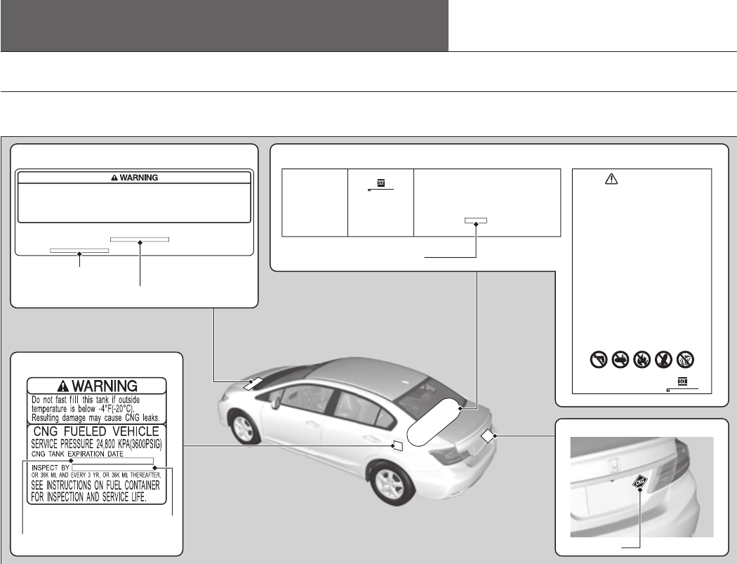
Safety Labels
4
Safe Driving
CNG Label Locations
These labels are in the locations shown. They give instructions and warnings on the CNG fuel system.
If a label comes off or becomes hard to read, contact a dealer for a replacement.
7+,6&217$,1(56+28/'
%(9,68$//<,163(&7('
$)7(5$027259(+,&/(
$&&,'(1725),5(
$1'$7/($67(9(5<
0217+625
0,/(6:+,&+(9(5&20(6
),567)25'$0$*(
$1''(7(5,25$7,21
36,*e)
$/7
31
e)72e)
1*9'27&)5
7<3(&217$,1(5
,)7+(5(,6$48(67,21$%2877+(3523(586(
,167$//$7,21250$,17(1$1&(2)7+,6&217$,1(5
&217$&76758&785$/&20326,7(6,1'8675,(6
(17(535,6(3/32021$&$
7(/
6(59,&(35(6685(N3D36,*
0$18)$&785(',1'27)0966
)2586(21/<:,7+7+(&217$,1(50$18)$&785(56
$33529('35(6685(5(/,()'(9,&(69$/9(6
&1*21/<'212786($)7(5
1*9)8(/7$1.6
7(67
'$7(
6(59
7(03
Structural Composites Industries
A WORTHINGTON CYLINDER COMPANY
7KLVF\OLQGHULVLQWHQGHGIRUXVHRQWKLVYHKLFOHWRVWRUHFRPSUHVVHGQDWXUDO
JDVPRWRUIXHO'RQRWXVHIRUDQ\RWKHUSXUSRVH
'RQRWDWWHPSWWRUHPRYHWKLVF\OLQGHUIURPWKHYHKLFOHRUWRVHUYLFHYHQWRU
PDLQWDLQWKLVF\OLQGHURUDQ\DWWDFKHGSDUWVXQOHVV\RXDUHVSHFLILFDOO\WUDLQHG
WRGRVR7KHF\OLQGHUPD\FRQWDLQUHVLGXDOJDVZKLFKSRVHVDILUHRUH[SORVLRQ
ULVN,PSURSHUYHQWLQJSURFHGXUHVZLOOFDXVHDVWDWLFHOHFWULFDOGLVFKDUJHZKLFK
FRXOGLJQLWHYHQWLQJQDV5HPRYDOVHUYLFLQJYHQWLQJQDGGLVSRVDOVKRXLGRQO\
EHGRQHE\DTXDOLILHGWHFKQLFLDQ
7KHPD[LPXPVHUYLFHSUHVVXUHIRUWKLVF\OLQGHULVSVLFRPSHQVDWHGWR
e)e&KRZHYHULQQRFDVHVKDOOWKHPD[LPXPILOOLQJSUHVVXUHH[FHHG
SVL
'RQRWDVVXPH\RXFDQDOZD\VVPHOOOHDNLQJJDV,I\RXVPHOOJDVRUIRU
DQ\UHDVRQVXVSHFWWKHF\OLQGHURUDQ\SDUWRIWKHIXHOV\VWHPLVOHDNLQJGR
QRWSDUNWKHYHKLFOHLQDQHQFORVHGDUHDVXFKDVDJDUDJH,PPHGLDWHO\
KDYHWKHYHKLFOHVHUYLFHGE\DTXDOLILHGWHFKQLFLDQ
,IWKLVYHKLFOHLVLQYROYHGLQDFROOLVLRQILUHRULISK\VLFDOGDPDJHLVREVHUYHG
RQWKHF\OLQGHURULWVDWWDFKPHQWVGRQRWSDUNWKHYHKLFOHLQDQHQFORVHGDUHD
VXFKDVDJDUDJH,PPHGLDWHO\KDYHWKHYHKLFOHVHUYLFHGE\DTXDOLILHG
WHFKQLFLDQ'RQRWILOOWKHF\OLQGHUXQWLOWKHYHKLFOHKDVEHHQVHUYLFHG
'RQRWH[SRVHF\OLQGHUWRWHPSHUDWXUHVLQH[FHVVRIGHJUHHV)DKUHQKHLW
'RQRWH[SRVHF\OLQGHUWRFRUURVLYHIOXLGVVXFKDVDFLGVDQGEDVHV
7+,6&</,1'(50867%(,167$//('$1'6(59,&('%<
48$/,),('7(&+1,&,$16,1$&&25'$1&(:,7+
1$7,21$/),5(3527(&7,21$662&,$7,2167$1'$5'
)25&2035(66('1$785$/*$69(+,&8/$5)8(/6<67(06
$1'$//$33/,&$%/()('(5$/67$7($1'/2&$/
5(*8/$7,2167(67('$1'$33529('9$/9($1'6$)(7<
5(/,()'(9,&(6$5(5(48,5('
6HHRWKHUZDUQLQJVSHUPDQHQWO\DIIL[HGWRWKLVYHKLFOH
'RQRWUHPRYHRUSDLQWRYHUWKLVODEHO
7KLVF\OLQGHUPXVWEHLQVSHFWHGE\DTXDOLILHGWHFKQLFLDQHYHU\WKUHH\HDUV
7+,6&</,1'(5&217$,16)/$00$%/(1$785$/*$681'(5
(;75(0(/<+,*+35(6685('($7+256(5,286,1-85<&$1
5(68/7)520,03523(5,167$//$7,21/$&.2),163(&7,21
$1'0$,17(1$1&(29(5),//,1*381&785,1*25'$0$*(
DRILL
1271488
PUNCTURE FIRE DROP CORROSIVE
'$1*(5
Structural Composites Industries
A WORTHINGTON CYLINDER COMPANY
THIS VEHICLE IS FUELED BY COMPRESSED NATURAL GAS STORED AT HIGH PRESSURE.
DO NOT ATTEMPT TO SERVICE FUEL SYSTEM WITHOUT PROPER SYSTEM DEPRESSURIZATION.
TO AVOID RISK OF INJURY, THIS VEHICLE SHOULD ONLY BE SERVICED BY A QUALIFIED
TECHNICIAN. CNG TANK PRESSURE RELIEF DEVICE WILL VENT AT 103˚C (217˚F).
DO NOT PARK OR SERVICE VEHICLE NEAR ANY SOURCE OF EXCESSIVE HEAT OR OPEN FLAME.
DO NOT USE PAINT OVEN FOR ANY PAINT REPAIRS.
SYSTEM SERVICE PRESSURE : 24.8MPA (3600PSIG)
BUILT BY : HONDA MFG. OF INDIANA, LLC
CNG TANK EXPIRATION DATE :
TOTAL WATER VOLUME OF CNG TANK
: 26.4 GAL. (100 L)
INSPECT BY OR 36K MI. AND EVERY 3 YR. OR 36K MI. THEREAFTER.
Hood
CNG Tank Expiration Date
Trunk Lid
CNG Tank
CNG Tank Production Date
CNG Label
Fuel Receptacle Lid
CNG Tank Expiration Date
First Inspection
First Inspection
SD
Home
Safety Labels After a Collision
5
Safe Driving
CNG tank expiration and production dates:
Are indicated on the labels. Have an authorized dealer or certified NGV technician
inspect the fuel tank every three years, or 36,000 miles, whichever comes first,
and replace it 15 years from its production date. Do not use an expired tank or
reuse the old tank for other purposes.
After a Collision
Have the fuel tank inspected by an authorized dealer or certified NGV technician.
Home
SD
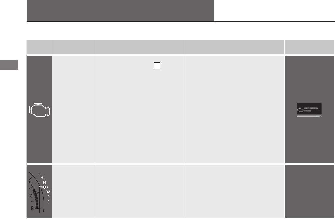
Indicators
6
Instrument Panel
Indicator Name On/Blinking Explanation Message
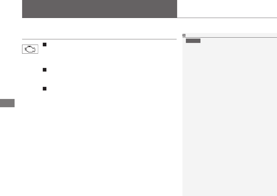
Malfunction
Indicator Lamp
• Comesonwhenyouturnthe
ignition switch to ON II , and
goes off either when the engine
starts or after several seconds
if the engine did not start. If
"readiness codes" have not been
set, it blinks five times before it
goes off.
• Comesonifthereisaproblem
with the emissions control system.
• Comesonifthereisaproblem
with the fuel system.
• Blinkswhenamisreinthe
engine's cylinders is detected.
• Readinesscodesarepartoftheon
board diagnostics for the emissions
control systems.
Testing of Readiness Codes - refer
to your Owner's Manual Information
Section
•Comes on while driving - Have
your vehicle checked by an authorized
Honda Civic Natural Gas dealer as soon
as possible.
•Blinks while driving - Stop in a safe
place where there are no flammable
objects. Stop the engine for 10 minutes
or more, and wait for it to cool down.
Then, take the vehicle to a dealer.
If the Malfunction Indicator Lamp
Comes On or Blinks P. 38
Shift Lever
Position
Indicator
• Indicatesthecurrentshiftlever
position.
Shifting P. 14 —
Indicator
IP
Home
Indicators
7
Instrument Panel
Indicator Name On/Blinking Explanation Message
Low Fuel
Indicator
• Comesonwhenyouturnthe
ignition switch to ON II , and
goes off when the engine starts.
• Comesonwhenthefuelreserveis
running low.
• Blinksifthereisaproblemwith
the fuel gauge.
•Comes on - Refuel your vehicle as
soon as possible.
When the outside air gets very cold
[below 25°F ( -4°C)], the pressure
of the natural gas inside the tank
goes down, and the fuel gauge may
indicate that you have less fuel than
what actually remains in the tank.
Keep this in mind if the low fuel
indicator comes on while you are
driving in cold weather.
•Blinks - Have your vehicle checked by
an authorized Civic Natural Gas dealer
as soon as possible.
IP
Home
Indicators intelligent Multi-Information Display (i-MID) Warning and Information Messages
8
Instrument Panel
intelligent Multi-Information Display (i-MID) Warning and Information Messages
Message Condition Explanation
FUEL LID OPEN
• Appearswhenthefuelreceptaclelidisopen.
Fuel Gauge P. 9
The following messages appear only on the i-MID. Press the (display/information) button to see the message again with the
system message indicator on.
IP
Home
9
Gauges and Displays
Instrument Panel
Gauges
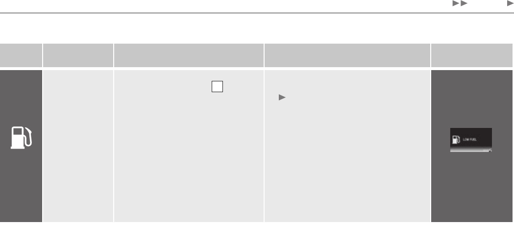
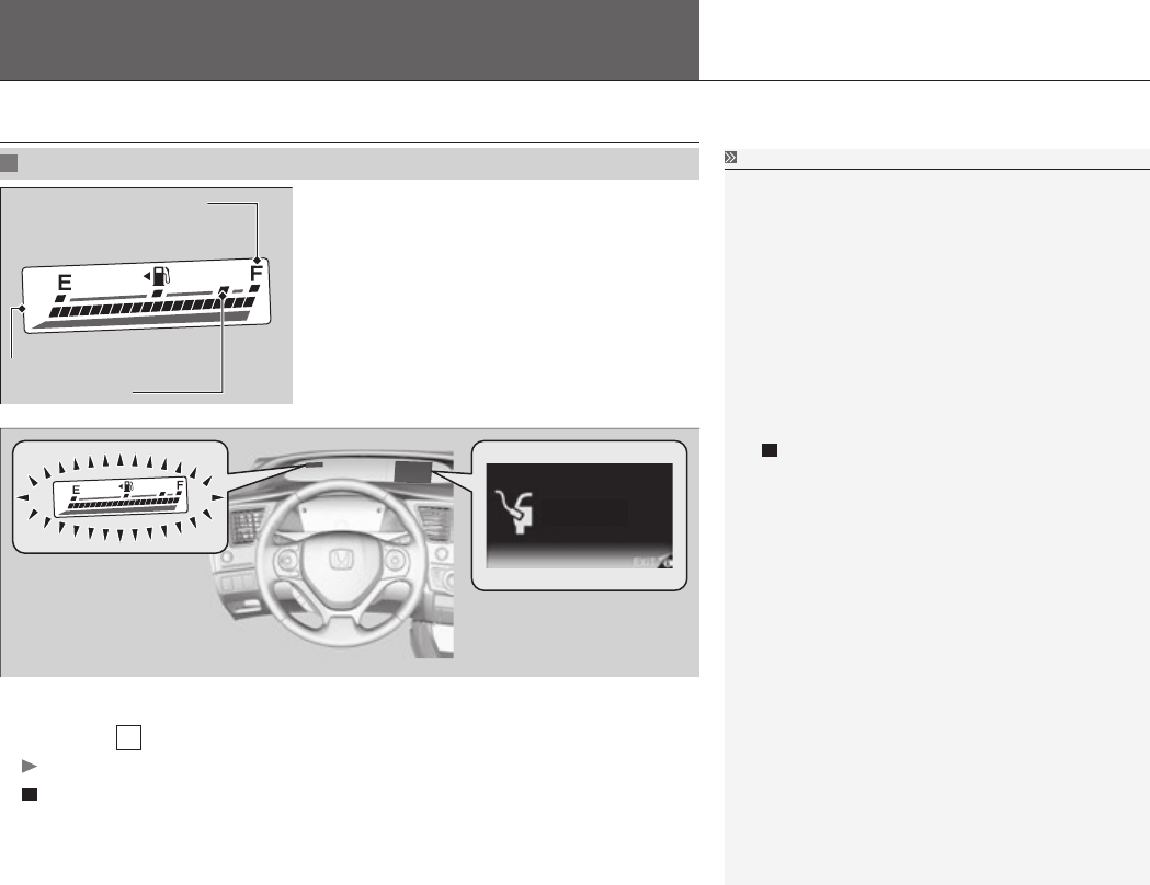
Fuel Gauge Fuel Gauge
The quantity of fuel remaining in the tank is
calculated based on the pressure and temperature
of the natural gas in the fuel tank.
The gauge, average fuel, range, and instant fuel
economy show more or less than the actual
amount. The tank temperature, fill method, and
ambient conditions may affect the pressure and
temperature of the natural gas.
You can choose when to reset the average fuel
economy.
Customized Features
P. 90, Owner's Manual
Refueling a small amount of gas may not trigger trip
A and the average fuel economy to reset.
FUEL LID OPEN
Displays the amount of fuel left in the fuel
tank.
The lower F mark indicates a full tank at a fill
pressure of 3,000 psi.
The upper F mark indicates a full tank at a fill
pressure of 3,600 psi.
If the fuel receptacle lid is open, the fuel gauge blinks when you turn the ignition
switch to ON II .
It stops blinking when you close the lid.
How to Refuel
P. 16
Upper F Mark
Lower F Mark
Fuel Gauge
IP
Home

Before Driving
10
Driving
Storing Cargo in the Trunk
Do not put large, heavy or pointed objects in the trunk. When storing items,
properly secure them so that they do not move around while driving. The fuel
tank is located in the trunk, and although a partition separates the tank from the
cargo space, large items or loose items can damage the fuel tank and fuel system
components.
Towing a Trailer
Your vehicle is not designed to tow a trailer. Attempting to do so can void your
warranties.
D
Home
11
When Driving
Continued
Driving
Starting the Engine
Starting the Engine
Keep your foot firmly on the brake pedal when
starting the engine.
The engine is harder to start in cold weather and
in thinner air found at altitudes above 8,000 feet
(2,400 meters).
When starting the engine in cold weather, turn
off all electrical accessories (the lights, heating
and cooling system, and rear defogger) in order to
reduce battery drain.
If you live in a region where winter is extremely
cold, an engine block heater will improve starting
and warming of the engine. If temperatures
consistently below -22°F (-30°C) are expected, the
coolant mixture should be changed to a higher
concentration to prevent freezing. Consult a dealer
for details.
If the exhaust system sounds abnormal or you
can smell exhaust gas inside the vehicle, have
your vehicle checked by a dealer. There may be a
problem with the engine or exhaust system.
Brake Pedal
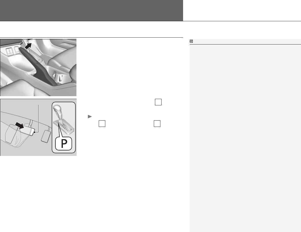
1. Make sure the parking brake is applied.
2. Check that the shift lever is in P, then
depress the brake pedal.
Although it is possible to start the vehicle
in
N
, it is safer to start it in
P
.
D
Home
When Driving Starting the Engine
12
Driving
3. Turn the ignition switch to ON II without
depressing the accelerator pedal.
You may hear a click from the in-tank fuel
shut-off valve.
4. Turn the ignition switch to START III
without depressing the accelerator pedal.
Starting the Engine
Do not hold the key in START III for more than 15
seconds.
If the engine does not start right away, wait for at
•
least 10 seconds before trying again.
If the engine starts, but then immediately stops,
•
wait at least 10 seconds before repeating step
4 while gently depressing the accelerator pedal.
Release the accelerator pedal once the engine
starts.
The immobilizer system protects your vehicle from
theft. If an improperly coded key (or other device) is
used, the engine’s fuel system is disabled.
Immobilizer System
P. 125, Owner’s Manual
After extended storage: If you ever parked your
vehicle for an extended period, open the trunk for
several minutes before starting the engine to allow
any natural gas vapors that may have accumulated
to dissipate.
D
Home

When Driving Automatic Transmission
13
Driving
Automatic Transmission
Creeping
The engine runs at a higher idle speed and creeping increases.
Keep the brake pedal firmly depressed when stopped.
Kickdown
Quickly depressing the accelerator pedal while driving uphill may cause the
transmission to drop to a lower gear, unexpectedly increasing vehicle speed.
Depress the accelerator pedal carefully, especially on slippery roads and curves.
D
Home
When Driving Shifting
14
Driving
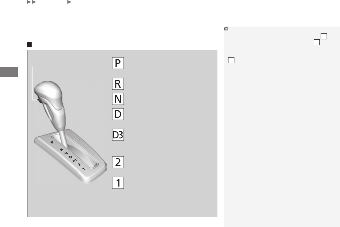
Shifting
Change the shift position in accordance with your driving needs.
Shift lever positions
Park
Used when parking or starting the
engine
Reverse
Used when reversing
Neutral
Used when idling
Drive
Used for normal driving (gears change
between 1st and 5th automatically)
Drive (D3)
Used when going up or down hills
Second
Used to increase engine braking
(the transmission is locked in 2nd gear)
First
Used to further increase engine braking
(the transmission is locked in 1st gear)
Release Button
Shifting
You cannot turn the ignition switch to LOCK 0 and
remove the key unless the shift lever is in P.
The vehicle may move forward very slightly even in
N while the engine is cold.
Depress the brake pedal firmly and, when necessary,
apply the parking brake.
D
Home
When Driving Shifting
15
Continued
Driving
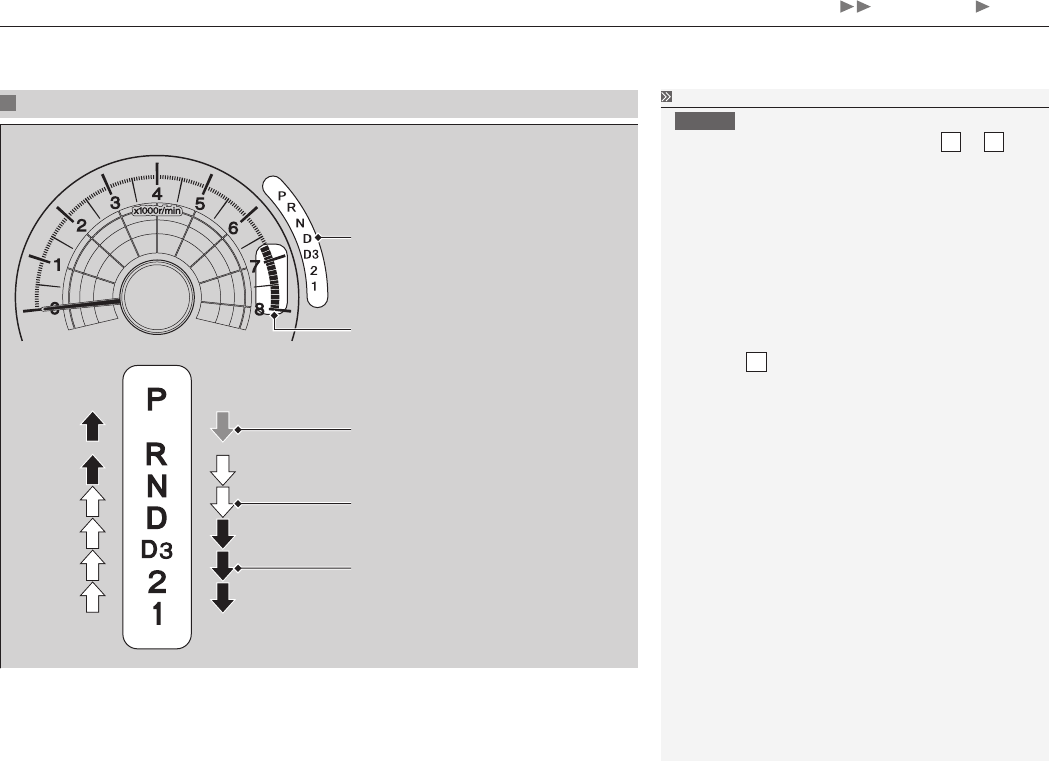
Shift Lever Operation
Shift Lever Position Indicator
Tachometer’s red zone
Depress the brake pedal and press
the shift lever release button to
shift.
Shift without pressing the shift
lever release button.
Press the shift lever release button
and shift.
Shift Lever Operation
NOTICE
When you change the shift lever from D to R and
vice versa, come to a complete stop and keep the
brake pedal depressed.
Operating the shift lever before the vehicle has
come to a complete standstill can damage the
transmission.
Use the shift lever position indicator to check the
lever position before pulling away.
Whichever position the shift lever is in when driving,
a blinking D indicator indicates a transmission
problem.
Avoid sudden acceleration and have the
transmission checked by a dealer as soon as
possible.
The fuel supply may be cut off if you drive at engine
speeds in or over the tachometer’s red zone (engine
speed limit). If this happens, you may experience a
slight jolt.
It may not be possible to operate the shift lever
if the brake pedal is applied while the shift lever
release button is held down.
Depress the brake pedal first.
D
Home
Refueling
16
Driving
Fuel Information
Only fuels that can be used
NFPA-52 and SAE J1616 standards
Use of a fuel that does not meet these standards can cause a decrease in engine
power and damage the emission controls.
Fuel tank capacity:
Slow filling
6.96 gasoline gallon equivalent (3,000 psi)
7.77 gasoline gallon equivalent (3,600 psi)
Fast filling
5.84 gasoline gallon equivalent (3,000 psi)
6.51 gasoline gallon equivalent (3,600 psi)
How to Refuel
There are two methods of refueling:
Fast filling
It takes about three to five minutes to fill up the fuel tank. This method is usually
available at stations designed to refuel natural gas vehicles.
During fast filling, the natural gas is warmed, causing the pressure in the tank to
rise and reduces the amount of fuel you can put in.
Slow filling
It takes about an hour and a half per GGE (Gasoline Gallon Equivalent) to fill up
the fuel tank. This method can be done using a vehicle refueling appliance.
Fuel Quality and Home Refueling
P. 3
Fuel Information
For information on the locations of the CNG fuel
stations:
49 States: Visit either http://www.afdc.energy.gov/
afdc/fuels/natural_gas_locations.html, or www.
cngprices.com.
Or call Gas Vehicle Coalition at (202) 824-7360.
California: Visit www.cngvc.org.
The location of the CNG pump can vary from
station to station, may not be clearly marked, or
be readily accessible during certain hours. It is
recommended that you call the station (the number
should be displayed with the address information)
to verify the location and availability of the CNG
pump before you arrive.
How to Refuel
WARNING
Compressed natural gas is flammable and
highly explosive. You could be killed or
seriously injured if leaking natural gas is
ignited.
If you suspect a leak, have your vehicle
immediately inspected and repaired by
an authorized Honda Civic Natural Gas
dealer.
D
Home
Refueling How to Refuel
17
Continued
Driving
Refueling Procedure Example How to Refuel
NOTICE
Using fast fill equipment at temperature below -4°F
(-20°C) may damage the fuel system, potentially
causing a leak.
Always observe all safety recommendations and
operating instructions on the refueling equipment.
Use a fuel filler nozzle that complies with ANSI/AGA
NGV-1-2008 standards.
The CNG filler nozzle mechanism may vary by
service station. Each nozzle standard has different
maximum pressure:
P24
•- 2,400 psi (16,500 kPa)
P30
•- 3,000 psi (20,700 kPa)
P36
•- 3,600 psi (24,800 kPa)
The refueling steps shown in this manual are the
typical fast fill refueling procedure. You may need
to go through different steps at a station with slow
fill equipment or other types of equipment. Always
follow the instructions provided on site.
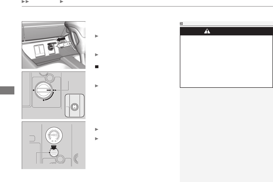
1. Stop your vehicle with the service station
pump on the left side of the vehicle in the
rear.
2. Turn off the engine.
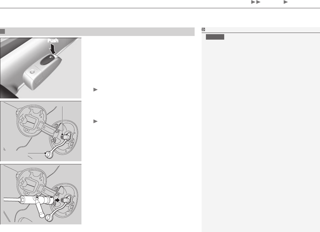
3. Push on the fuel receptacle lid release
handle at the foot of the driver’s seat.
The fuel receptacle lid opens.
4. Remove the receptacle dust cap from the
fuel receptacle.
Clean off any dirt or debris around the
fuel receptacle.
5
.Securely connect the CNG fill nozzle to the
fuel receptacle.
Push
Fuel Receptacle
Receptacle
Dust Cap
D
Home
Refueling How to Refuel
18
Driving
How to Refuel
If you hear or see fuel/vapor leaking from the
nozzle-receptacle connection, stop refueling
immediately. Turn off the refueling station, remove
the nozzle, reconnect it to the receptacle, and begin
refueling again. Dirt or debris adhered to the inside
of the fuel receptacle can cause a gas leak. Remove
dirt or debris from the CNG filler nozzle with a
clean, dry rag.
If it continues to leak, have an authorized CNG
dealer inspect the sealing O-ring in the fuel
receptacle. It may be missing, damaged, or worn.
If you are not sure how to operate the refueling
station, ask for assistance.
6. Turn the lever until the arrows on the
nozzle point to each other, then follow
the instructions on the refueling station to
begin refueling.
While refueling, you may hear a chattering
sound. This is normal.
7. Refueling will stop automatically when the
tank is full. Follow the instructions on the
refueling station to turn it off.
8. Disconnect the CNG fill nozzle from the
fuel receptacle by slowly turning the lever
on the nozzle 180 degrees.
You may hear a brief hissing sound as a
small amount of gas escapes, and may
detect a slight gas odor. This is normal.
9. After filling, replace the receptacle dust
cap on the fuel receptacle securely.
Shut the fuel receptacle lid by hand.
D
Home
19
Maintaining the Fuel System
Maintenance
Your vehicle’s fuel system must be maintained and repaired by an authorized Civic
Natural Gas dealer or a certified NGV technician. The fuel system has no user-
serviceable parts, and its components must not be modified.
See instructions on fuel container for inspection and service life.
Maintaining the Fuel System
Service Pressure: 3,600 psi (24,800 kPa)
CNG Label Locations
P. 4
WARNING
Tampering with, or improperly
maintaining the high-pressure fuel system
can cause a dangerous condition in which
you can be seriously hurt or killed.
Never attempt to modify the fuel system,
and always have fuel system maintenance
performed by an authorized Honda Civic
Natural Gas dealer, or a qualified NGV
technician.
Indoor Vehicle Storage
If you store your vehicle indoors, make sure there is adequate ventilation. We
recommend that you also install a natural gas leak detector.
M
Home

20
Maintenance
Maintenance MinderTM
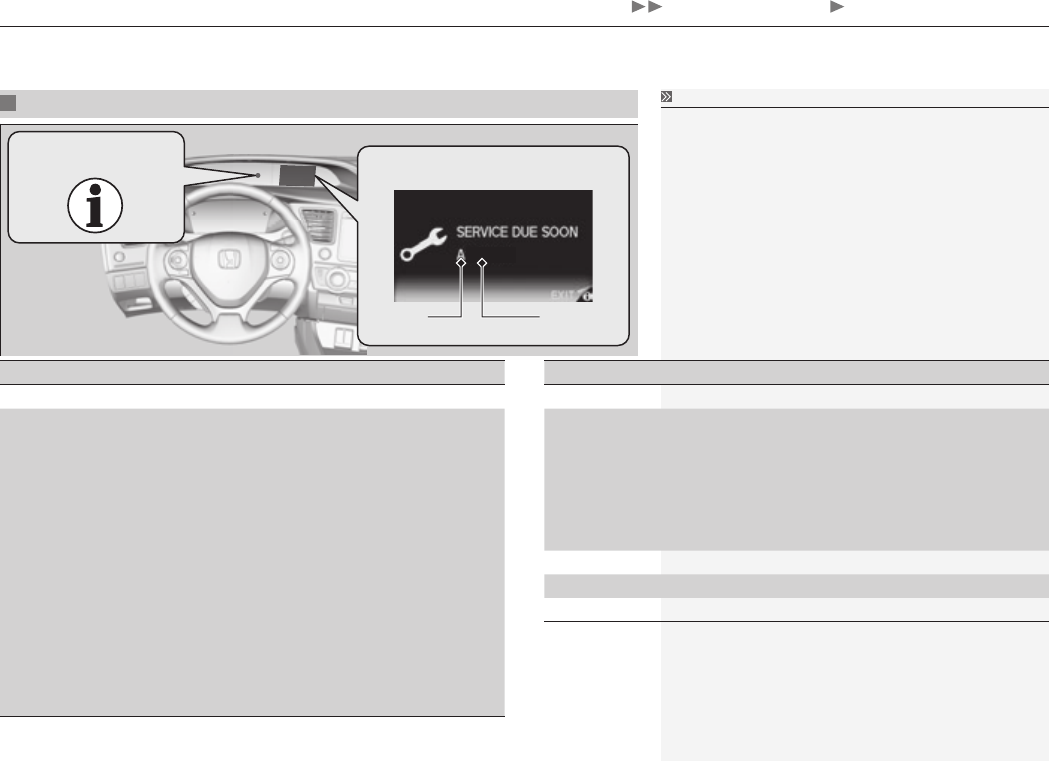
Your vehicle displays engine oil life and maintenance service items on the
intelligent multi-information display (i-MID) to show you when you should have a
dealer do engine oil replacement and indicated maintenance service.
Refer to the important safety precautions and instructions in the Owner's Manual.
M
Home
21
Maintenance
Maintenance MinderTM To Use Maintenace MinderTM
Maintenance Service Items
2345
Maintenance Service Items
Independent of the Maintenance Minder
•
information, replace the brake fluid every 3 years.
Inspect idle speed every 160,000 miles (256,000
•
km).
Adjust the valves during services A, B, 1, 2, or 3 if
•
they are noisy.
CODE Maintenance Main Items
A Replace engine oil• *1
B Replace engine oil• *1 and oil filter
Replace fuel filter element (low pressure)•
Drain fuel filter (high pressure)•
Inspect front and rear brakes/service as necessary•
Check parking brake adjustment•
Inspect tie rod ends, steering gearbox, and boots•
Inspect suspension components•
Inspect driveshaft boots•
Inspect brake hoses and lines (Including ABS/VSA)•
Inspect all fluid levels and condition of fluids•
Inspect exhaust system• #
Inspect fuel lines and connections• #
Check the expiration date for TRK bottle• *2
CODE Maintenance Sub Items
1 Rotate tires•
2 Replace air cleaner element• *3
Replace dust and pollen filter• *4
Replace fuel filter element (high pressure)•
Inspect drive belt•
Inspect valve clearance•
Inspect fuel tank• *5
3 Replace transmission fluid•
4 Replace spark plugs•
5 Replace engine coolant•
*1: If a message SERVICE does not appear more than 12 months after the display is reset, change the
engine oil every year.
*2: Models with tire repair kit
# : See information on maintenance and emissions warranty.
*3: If you drive in dusty conditions, replace the air cleaner element every 15,000 miles (24,000 km).
*4: If you drive primarily in urban areas that have high concentrations of soot in the air from industry and
from diesel-powered vehicles, replace the dust and pollen filter every 15,000 miles (24,000 km).
*5: If sub item 2 does not appear more than 36 months after the display is reset, inspect the fuel tank
every three years.
See CNG tank expiration and production dates on page 5 for inspection and replacement
information. Fuel tank should be replaced 15 years after it was manufactured.
System Message
Indicator Maintenance Minder
Message
Main
Item
Sub Items
M
Home
Maintenance Under the Hood
22
Maintenance
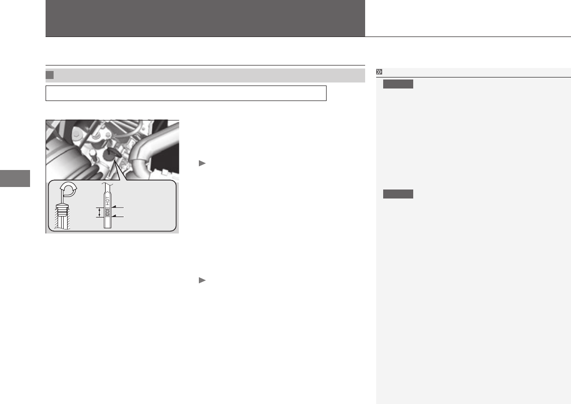
Transmission Fluid
Automatic Transmission Fluid
Specified fluid: Honda ATF DW-1 (automatic transmission fluid)
Check the fluid level when the engine is at normal operating temperature.
HOT
Range
Upper Mark
Lower Mark
1. Park on level ground, and start the engine.
2. Wait until the radiator fan starts and then
turn off the engine.
Perform step 3 after waiting for about
60 seconds (less than 90 seconds).
3. Remove the dipstick (yellow loop) from the
transmission and wipe it with a clean cloth.
4. Insert the dipstick all the way back into
the transmission securely, as shown in the
image.
5. Remove the dipstick and check the fluid
level.
It should be between the upper and
lower marks in the HOT range.
6. If the level is below the lower mark, add
fluid into the dipstick hole to bring it to the
level between the upper and lower marks,
and have your vehicle checked by a dealer
immediately.
Automatic Transmission Fluid
NOTICE
Do not mix Honda ATF DW-1 with other
transmission fluids.
Using a transmission fluid other than Honda ATF
DW-1 may adversely affect the operation and
durability of your vehicle's transmission, and
damage the transmission.
Any damage caused by using a transmission fluid
that is not equivalent to Honda ATF DW-1 is not
covered by Honda's new vehicle warranty.
NOTICE
Pour the fluid slowly and carefully so you do not
spill any. Clean up any spills immediately; they can
damage components in the engine compartment.
M
Home
23
Replacing Light Bulbs
Continued
Maintenance
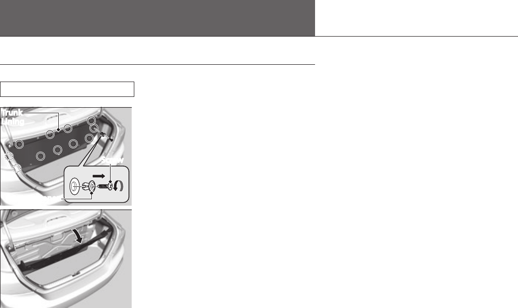
High-Mount Brake Light Bulb
When replacing, use the following bulb.
High-Mount Brake Light: 21W
1. Open the trunk.
2. Remove the screw from the center of each
trunk lining fastener, then remove the
fasteners.
3. Pull the upper edge of the trunk lining
down.
Trunk
Lining
Screw
Fastener
M
Home
24
Maintenance
Replacing Light Bulbs High-Mount Brake Light Bulb
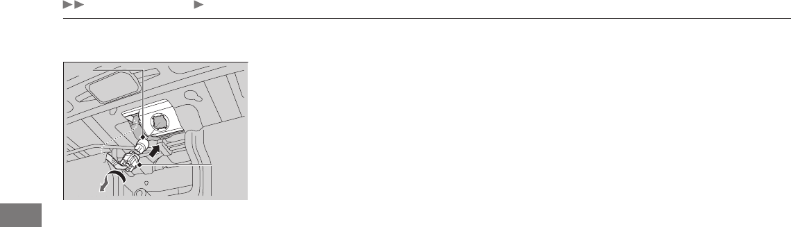
4. Turn the socket to the left and remove it.
5. Remove the old bulb and insert a new
bulb.
Bulb
Socket
M
Home
25
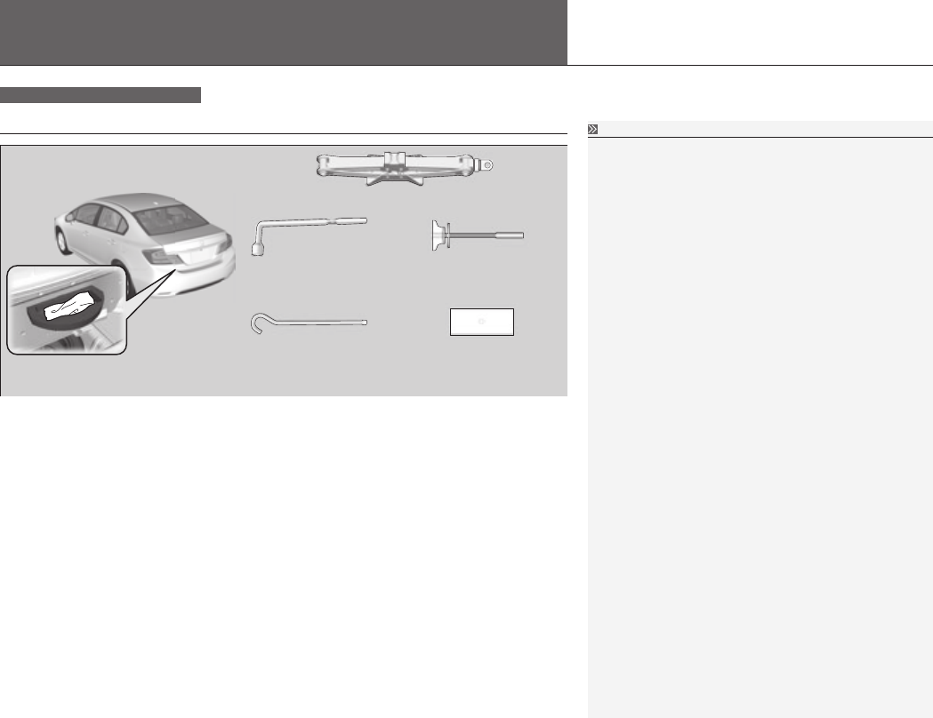
Tools
Handling the Unexpected
Type of Tools
The tools are stored in the trunk.
Models with compact spare tire
Type of Tools
Jack Handle Bar
Jack
Wing Bolt
(for mounting a flat tire)
Support Plate
Wheel Nut Wrench/
Jack Handle
HU
Home
If a Tire Goes Flat
26
Handling the Unexpected
To change a flat tire, follow the instructions in the Owner’s Manual.
To remove the spare tire, tools and the jack from the trunk and to store the flat
tire, follow the instructions in this section.
Removing the Spare Tire, Tools and the Jack
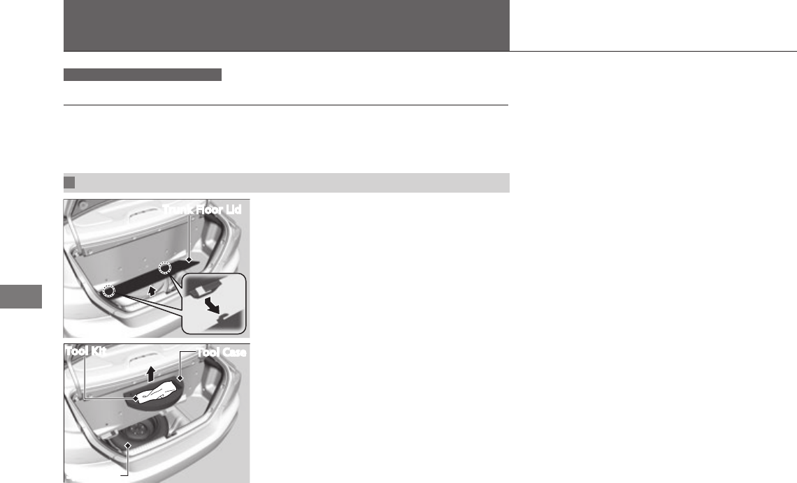
Trunk Floor Lid
Tool Kit Tool Case
Spare Tire
1. Open the trunk.
2. Remove the trunk floor lid.
3. Take the tool case out of the spare tire.
Models with compact spare tire
Changing a Flat Tire
HU
Home
27
Continued
Handling the Unexpected
If a Tire Goes Flat Changing a Flat Tire
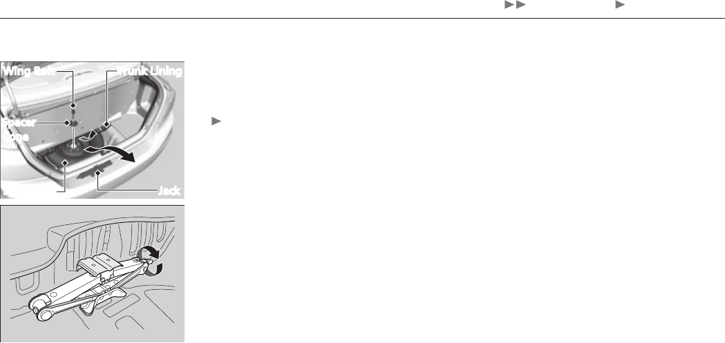
4. Unscrew the wing bolt and remove the
spacer cone.
5. Take the spare tire out of its well.
Bend the lower part of the trunk lining
upward to enlarge the opening.
6. Turn the jack’s end counterclockwise to
loosen it, then remove the jack.
Wing Bolt
Jack
Spacer
Cone
Spare Tire
Trunk Lining
HU
Home
28
Handling the Unexpected
If a Tire Goes Flat Changing a Flat Tire
Storing a Flat Tire
WARNING
Loose items can fly around the interior
in a crash and can seriously injure the
occupants.
Store the wheel, jack, and tools securely
before driving.
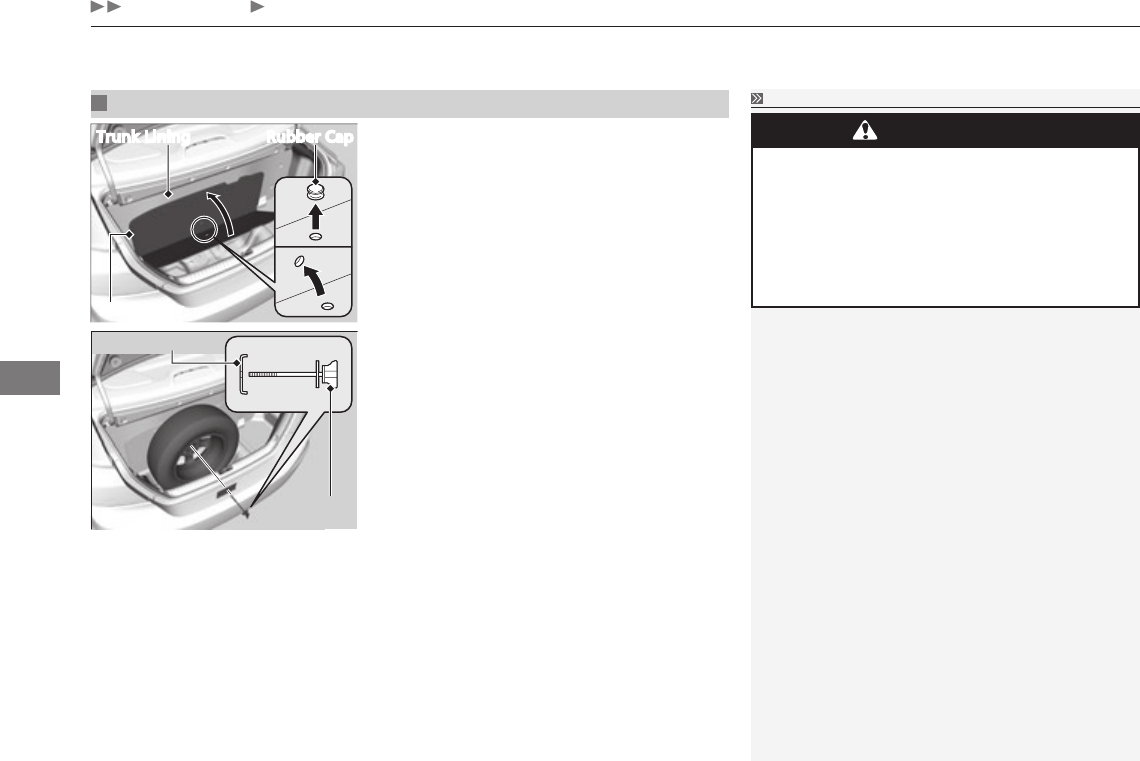
Storing a Flat Tire
1. Open the trunk.
2. Raise the trunk floor and the lower part of
the trunk lining.
3. Remove the rubber caps from the holes in
the trunk floor and the trunk lining, then
align both holes.
4. Place the flat tire straight up in the trunk,
with the outside of the wheel facing
forward.
5. Take the support plate and the wing bolt
out of the tool kit. Put the plate on the
wing bolt.
6. Insert the wing bolt through the hole in
the center of the wheel and the trunk
lining, then tighten the bolt.
7. Store the spacer cone and the spare tire
wing bolt in the tool kit.
Trunk Lining Rubber Cap
Trunk Floor
Support Plate
Wing Bolt
HU
Home
29
Continued
Handling the Unexpected
If a Tire Goes Flat Temporarily Repairing a Flat Tire
Models with tire repair kit
Temporarily Repairing a Flat Tire
This vehicle is not equipped with a spare tire. If the tire has a large cut or is
otherwise severely damaged, you will need to have the vehicle towed. If the tire
only has a small puncture, from a nail for instance, you can use the temporary tire
repair kit so that you can drive to the nearest service station for a more permanent
repair.
If a tire goes flat while driving, grasp the steering wheel firmly, and brake gradually
to reduce speed. Then stop in a safe place.
1. Park the vehicle on firm, level, and non-slippery surface and apply the parking
brake.
2. Put the shift lever in P.
3. Turn on the hazard warning lights and turn the ignition switch to LOCK 0.
When towing a trailer, unhitch the trailer.
Getting Ready to Temporarily Repair the Flat Tire
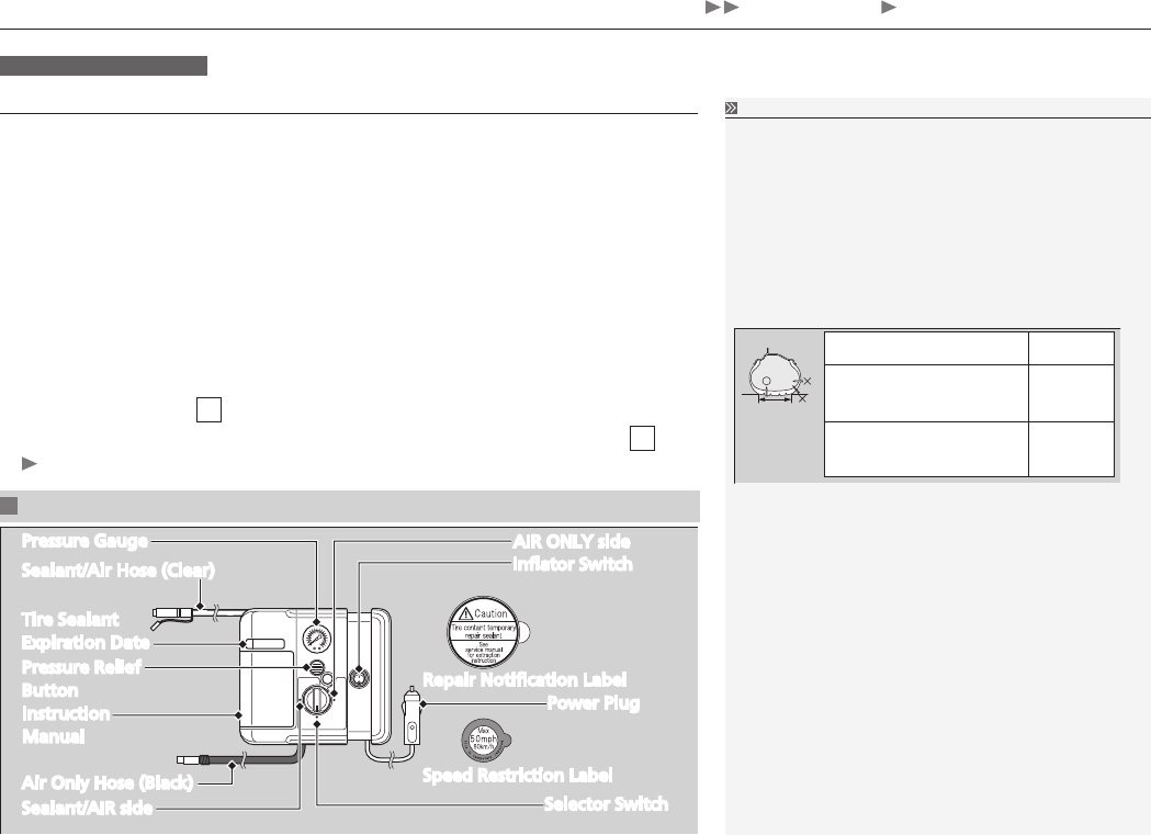
AIR ONLY side
Inflator Switch
Repair Notification Label
Power Plug
Speed Restriction Label
Selector Switch
Pressure Gauge
Sealant/Air Hose (Clear)
Tire Sealant
Expiration Date
Pressure Relief
Button
Instruction
Manual
Air Only Hose (Black)
Sealant/AIR side
Temporarily Repairing a Flat Tire
The kit should not be used in the following
situations. Instead, contact a dealer or a roadside
assistant to have the vehicle towed.
The tire sealant has expired.
•
More than two tires are punctured.
•
The puncture or cut is larger than 3/16 inch (4 mm).
•
The tire side wall is damaged or the puncture is
•
outside the tire contact area.
When the puncture is: Kit Use
Smaller than 3/16 inch
(4 mm) Yes
Larger than 3/16 inch
(4 mm) No
Damage has been caused by driving with the tire
•
extremely under inflated.
The tire bead is no longer seated.
•
The rim is damaged.
•
Do not remove a nail or screw that punctured the
tire. If you remove it from the tire, you may not be
able to repair the puncture using the kit.
HU
Home
30
Handling the Unexpected
If a Tire Goes Flat Temporarily Repairing a Flat Tire
1. Remove the trunk floor lid.
2. Take the kit out of the case.
Place the kit face up, on flat ground
near the flat tire, and away from traffic.
Do not place the kit on its side.
Getting Ready to Temporarily Repair the Flat Tire
When making a temporary repair, carefully read the
instruction manual provided with the kit.
In cold temperatures, the sealant may not flow
easily. In this situation, warm it up for five minutes
before using.
HU
Home
31
Continued
Handling the Unexpected
If a Tire Goes Flat Temporarily Repairing a Flat Tire
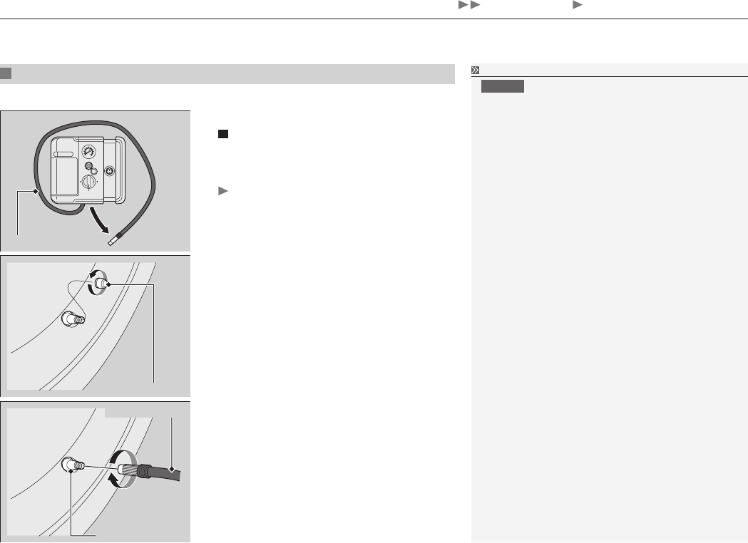
Injecting Sealant and Air
1. Remove the valve cap from the tire valve
stem.
2. Remove the sealant/air hose from the
packaging.
3. Attach the sealant/air hose onto the tire
valve stem. Screw it until it is tight.
Valve Stem
Valve Cap
Sealant/Air Hose
Sealant/Air Hose
Valve Stem
Injecting Sealant and Air
WARNING
Tire sealant contains substances that are
harmful and can be fatal if swallowed.
If accidentally swallowed, do not induce
vomiting. Drink plenty of water and get
medical attention immediately.
For skin or eye contact, flush with cool
water and get medical attention if
necessary.
In cold temperatures, the sealant may not flow
easily. In this situation, warm it up for five minutes
before using.
The sealant can permanently stain clothing and
other materials. Be careful during handling and
wipe away any spills immediately.
HU
Home
32
Handling the Unexpected
If a Tire Goes Flat Temporarily Repairing a Flat Tire
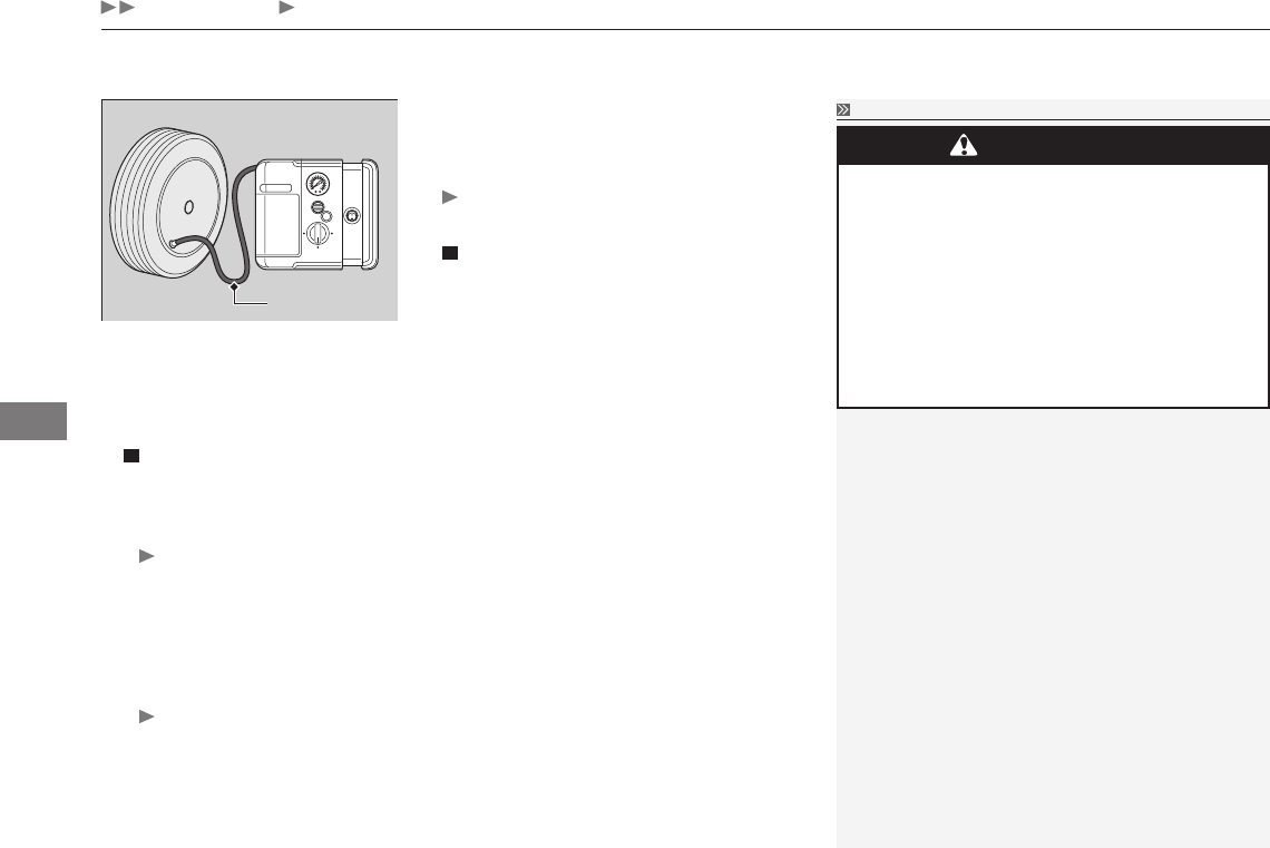
4. Plug in the compressor to the accessory
power socket.
Be careful not to pinch the cord in a door
or window.
5. Start the engine.
Keep the engine running while injecting
sealant and air.
Carbon Monoxide Gas
P. 64, Owner's Manual
6. Turn the selector switch to SEALANT/AIR.
7. Press the inflator switch to turn on the
compressor.
The compressor starts injecting sealant
and air into the tire.
8. When the sealant injection is complete,
continue to add air.
9. After the air pressure reaches 30 psi (210
kPa), turn off the kit.
To check the pressure, occasionally turn
off the compressor and read the gauge.
Injecting Sealant and Air
SEALANT/AIR Side
Pressure Gauge
WARNING
Running the engine with the vehicle in
an enclosed or even partly enclosed area
can cause a rapid build-up of toxic carbon
monoxide.
Breathing this colorless, odorless gas can
cause unconsciousness and even death.
Only run the engine to power the air
compressor with the vehicle outdoors.
NOTICE
Do not operate the tire repair kit compressor
for more than 15 minutes. The accessory power
socket and compressor can overheat and become
permanently damaged.
Until the sealant injection is complete, the pressure
shown on the pressure gauge will appear higher
than actual. After the sealant injection is complete
the pressure will drop and then begin to rise again
as the tire is inflated with air. This is normal. To
accurately measure the air pressure using the gauge,
turn the air compressor off only after the sealant
injection is complete.
If the required air pressure is not reached within
10 minutes, the tire may be too severely damaged
for the kit to provide the necessary seal and your
vehicle will need to be towed.
HU
Home
33
Continued
Handling the Unexpected
If a Tire Goes Flat Temporarily Repairing a Flat Tire
10
. Unplug the power plug from the accessory
power socket.
11
. Unscrew the sealant/air hose from the tire
valve stem. Reinstall the valve cap.
12
. Press the pressure relief button until the
gauge returns 0 psi (0 kPa).
13
. Apply the repair notification label to the
flat surface of the wheel.
The wheel surface must be clean to
ensure the label adheres properly.
Repair Notification Label
Valve Stem
Sealant/Air Hose
Distributing the Sealant in the Tire
Repair Notification Label
1. Apply the speed restriction label to the
location as shown.
2. Drive the vehicle for about 10 minutes.
Do not exceed 50 mph (80 km/h).
3. Stop the vehicle in a safe place.
Injecting Sealant and Air
See a Honda dealer for a replacement sealant bottle
and proper disposal of an empty bottle.
Distributing the Sealant in the Tire
Stop and recheck the air pressure after every 10
minutes of driving as necessary until you reach the
nearest service station where you are able to have
the tire permanently repaired or replaced.
HU
Home
34
Handling the Unexpected
If a Tire Goes Flat Temporarily Repairing a Flat Tire
4. Attach the air only hose onto the tire valve
stem. Screw it until it is tight.
5. Turn the selector switch to AIR ONLY.
Do not turn the air compressor on to
check the pressure.
Inflating An Under-inflated Tire
P. 35
Air Only Hose
Distributing the Sealant in the Tire
WARNING
Running the engine with the vehicle in
an enclosed or even partly enclosed area
can cause a rapid build-up of toxic carbon
monoxide.
Breathing this colorless, odorless gas can
cause unconsciousness and even death.
Only run the engine to power the air
compressor with the vehicle outdoors.
6. If the air pressure is:
•Lessthan19psi(130kPa):
Do not add air or continue driving. The leak is too severe. Call for help and
have your vehicle towed.
Emergency Towing
P. 442, Owner's Manual
•30psi(210kPa)ormore:
Continue driving for another 10 minutes or until you reach the nearest service
station. Do not exceed 50 mph (80 km/h).
If the air does not go down after the 10 minute drive, you do not need to
check the pressure any more.
•Greaterthan19psi(130kPa),butlessthan30psi(210kPa):
Turn the air compressor on to inflate the tire until the tire pressure reaches
30 psi (210 kPa).
Then drive carefully for 10 more minutes or until you reach the nearest service
station. Do not exceed 50 mph (80 km/h).
You should repeat this procedure as long as the air pressure is within this
range.
7. Press the pressure relief button until the gauge returns to 0 psi (0 kPa).
8. Repackage and properly stow the kit.
HU
Home
35
Continued
Handling the Unexpected
If a Tire Goes Flat Temporarily Repairing a Flat Tire
Inflating An Under-inflated Tire
You can use the kit to inflate a non-punctured under-inflated tire.
1. Remove the trunk floor lid.
Getting Ready to Temporarily Repair the
Flat Tire P. 29
2. Remove the kit from the case.
Place the kit on flat ground near the tire
to be inflated, away from traffic.
3. Place the kit, face up, on flat ground near
the flat tire, away from traffic. Do not
place the kit on its side.
4. Remove the air only hose from the kit.
5. Remove the valve cap.
6. Attach the air only hose onto the tire valve
stem. Screw it until it is tight.
Valve Cap
Air Only Hose
Valve Stem
Inflating An Under-inflated Tire
NOTICE
Do not operate the temporary tire repair kit
compressor for more than 15 minutes. The
accessory power socket and compressor can
overheat and become permanently damaged.
Air Only Hose
HU
Home
36
Handling the Unexpected
If a Tire Goes Flat Temporarily Repairing a Flat Tire
7. Plug in the kit to the accessory power
socket.
Be careful not to pinch the cord in a door
or window.
8. Start the engine.
Keep the engine running while injecting
air.
Carbon Monoxide Gas
P. 64, Owner's Manual
9. Turn the selector switch to AIR ONLY.
10
. Press the inflator switch to turn on the kit.
The compressor starts to inject air into the
tire.
11
. Inflate the tire to the specified air pressure.
12
. Turn off the kit.
Check the pressure gauge on the air
compressor.
If overinflated, press the pressure relief
button.
13
. Unplug the kit from the accessory power
socket.
14
. Unscrew the air only hose from the tire
valve stem. Reinstall the valve cap.
15
. Press the pressure relief button until the
gauge returns 0 psi (0 kPa).
16
. Repackage and properly stow the kit.
Inflating An Under-inflated Tire
AIR ONLY
Side
Pressure Relief Button
WARNING
Running the engine with the vehicle in
an enclosed or even partly enclosed area
can cause a rapid build-up of toxic carbon
monoxide.
Breathing this colorless, odorless gas can
cause unconsciousness and even death.
Only run the engine to power the air
compressor with the vehicle outdoors.
ON
HU
Home
37
Fuel Leaks
Handling the Unexpected
If a Fuel Leak is Detected
If you smell natural gas or hear a hissing sound, except when refueling, the fuel
system may have a leak.
If a Fuel Leak is Detected
WARNING
Compressed natural gas is flammable and
highly explosive. You could be killed or
seriously injured if leaking natural gas is
ignited.
If you suspect a leak, have your vehicle
immediately inspected and repaired by an
authorized Honda Civic Natural Gas
dealer.
Do not jump start your vehicle if you suspect a gas
leak.
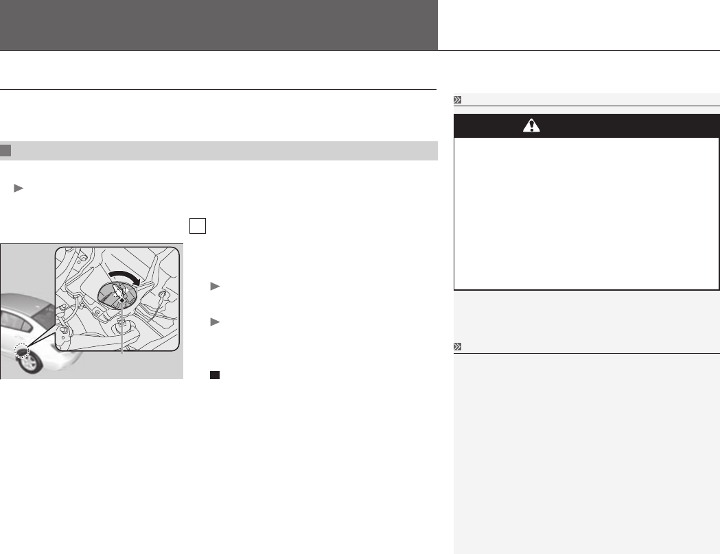
Turning Off the Manual Shut-Off Valve
We recommend that you locate the valve before
driving so that you can turn it off quickly if
necessary.
Turn off the valve if you ever suspect a fuel leak or
are involved in an accident.
Turn the manual shut-off valve to OFF also when
you are storing your vehicle for an extended period.
Turning Off the Manual Shut-Off Valve
4. Turn the manual shut-off valve one-quarter
turn clockwise (located as shown).
The valve is turned to OFF.
5. Call a professional towing service.
You cannot continue driving. Have the
vehicle towed to an authorized Civic
Natural Gas dealer.
Emergency Towing
P. 442, Owner's
Manual
1. Park your vehicle outside in a well-ventilated area. Set the parking brake.
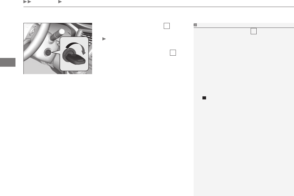
Keep away from heat, sparks, and flame.
2. Open all the windows and trunk for ventilation.
3. Turn the ignition switch to LOCK 0.
Manual Shut-Off
Valve
HU
Home
Indicator, Coming On/Blinking
38
Handling the Unexpected
If the Malfunction Indicator Lamp Comes On or
Blinks If the Malfunction Indicator Lamp Comes On or Blinks
NOTICE
If you drive with the malfunction indicator lamp on,
the emissions control system and the engine could
be damaged.
If the malfunction indicator lamp blinks again when
restarting the engine, drive to the nearest dealer at
31 mph (50 km/h) or less for an inspection.
Reasons for the indicator lamp to come on or blink
Comes on when there is a problem with the engine emissions control •
system, or the fuel system.
Blinks when engine misfiring is detected. •
What to do when the indicator lamp comes on
Avoid high speeds and immediately get your vehicle inspected at an
authorized Civic Natural Gas dealer.
What to do when the indicator lamp blinks
Park the vehicle in a safe place with no flammable items and wait at
least ten minutes or more with the engine stopped until it cools.
HU
Home

39
Fuses
Continued
Handling the Unexpected
To check and replace fuses, follow the instructions in the Owner’s Manual.
Since your vehicle’s fuses are different from the standard gasoline model’s fuses,
determine from the chart or the diagram on the fuse box label, which fuse or fuses
control that device.
Current (Amps) ratings in brackets indicate a fuse in that location for a device that
may not be equipped on your vehicle.
HU
Home
40
Handling the Unexpected
Fuses Fuse Locations
Circuit Protected Amps
1
EPS 70 A
− (40 A)
ABS/VSA Motor 30 A
ABS/VSA FSR 30 A
− (30 A)
Main Fuse 100 A
2
IG Main 50 A
Fuse Box Main 60 A
Fuse Box Main 2 60 A
Headlight Main 30 A
− (30 A)
Rear Defogger 30 A
− (30 A)
Blower 40 A
− (30 A)
Sub Fan Motor 20 A
Main Fan Motor 20 A
3 − −
4 Left Headlight Low Beam 15 A
5 ST MG 7.5 A
6 Right Headlight Low Beam 15 A
7 − −
8 − −
9 − −
10 − −
Circuit Protected Amps
11 Oil Level 7.5 A
12 Fog Lights*(20 A)
13 Driver's Power Seat (Sliding)*(20 A)
14 Hazard 10 A
15 FI Sub 15 A
16 IG Coil 15 A
17 Stop 15 A
18 Horn 10 A
19 Premium Amp*(20 A)
20 INJ (15 A)
21 IGP 15 A
22 DBW 15 A
23 H/L LO 20 A
24 Driver's Power Seat
(Reclining)*(20 A)
25 MG Clutch 7.5 A
26 − −
27 SMALL 20 A
28 Interior Lights 7.5 A
29 Back Up 10 A
Fuse Locations
If any electrical devices are not working,
turn the ignition switch to LOCK 0 and
check to see if any applicable fuse is
blown.
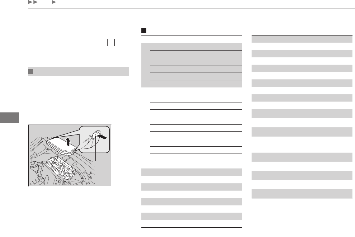
Engine Compartment Fuse Box
Located near the brake fluid reservoir.
Push the tabs to open the box.
Fuse locations are shown on the fuse box
cover. Locate the fuse in question by the
fuse number and box cover number.
Circuit protected and fuse rating
* Not available on all models
Tab
HU
Home
41
Handling the Unexpected
Fuses Fuse Locations
Interior Fuse Box Circuit Protected Amps
9 Door Lock Motor 1 (Unlock) 15 A
10 − −
11 Moonroof*(20 A)
12 Accessory Power Socket
(Center Console)*(20 A)
13 − −
14 Seat Heaters*(15 A)
15 Driver's Door Lock Motor
(Unlock) (10 A)
16 − −
17 − −
18 − −
19 ACC 7.5 A
20 ACC Key Lock 7.5 A
21 Daytime Running Lights 7.5 A
22 HAC 7.5 A
23 HAC*(7.5 A)
24 ABS/VSA 7.5 A
25 ACC*(7.5 A)
26 − −
27 Accessory Power Socket
(Front) 20 A
28 Washer (15 A)
29 ODS 7.5 A
30 Driver's Door Lock Motor
(Lock) (10 A)
Circuit Protected Amps
31 SMART*(10 A)
32 Door Lock Motor 2 (Lock) 15 A
33 Door Lock Motor 1 (Lock) 15 A
34 Small Lights 7.5 A
35 Illumination 7.5 A
36 − −
37 − −
38 Left Headlight High Beam 10 A
39 Right Headlight High Beam 10 A
40 TPMS (7.5 A)
41 Door Lock 20 A
42 Driver's Power Window 20 A
43 Rear Passenger's Side Power
Window (20 A)
44 Front Passenger's Side
Power Window 20 A
45 Rear Driver's Side Power
Window (20 A)
46 Wiper (30 A)
−STS*(7.5 A)
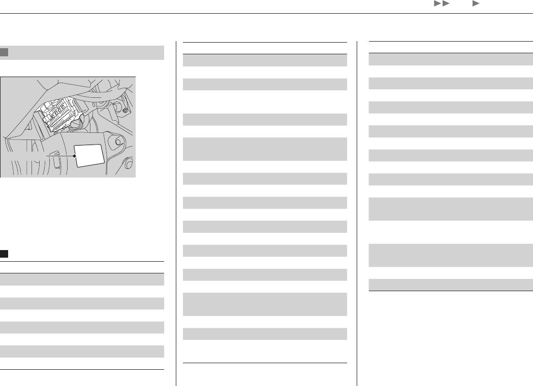
Located under the dashboard.
Fuse locations are shown on the label on
the side panel.
Locate the fuse in question by the fuse
number and label number.
Circuit protected and fuse rating
Circuit Protected Amps
1 HAC Option*(20 A)
2ACG 10 A
3SRS 10 A
4 Fuel Pump 15 A
5Meter 7.5 A
6 Power Window 7.5 A
7 VB SOL (15 A)
8 Door Lock Motor 2 (Unlock) 15 A
* Not available on all models
Fuse Label
HU
Home
Specifications
42
Information
Vehicle Specifications
Model Honda Civic 4-Door Natural Gas
No. of Passengers:
Front
Rear
Total
2
3
5
Weights:
Gross Vehicle Weight
Rating
3,870 lbs (1,755 kg)
Gross Axle Weight
Rating (Front) 2,007 lbs (910 kg)
Gross Axle Weight
Rating (Rear) 1,863 lbs (845 kg)
Air Conditioning:
Refrigerant Type
Charge Quantity
Lubricant Type
HFC-134a (R-134a)
13.2 – 15.0 oz (375 – 425 g)
SP-10
Engine Specifications
Displacement 110 cu-in (1,798 cm3)
Spark Plugs NGK SILKR8B8DS
Fuel
Fuel Tank
Service Pressure
3,600 psi (24,800 kPa) at 70°F (21°C)
Fuel Tank
Capacity
3,000 psi:
Slow filling
Fast filling
6.96 GGE
5.84 GGE
3,600 psi:
Slow filling
Fast filling
7.77 GGE
6.51 GGE
Washer Fluid
Tank Capacity 2.6 US qt (2.5 ℓ)
Light Bulbs
Headlights (Low Beam) 51W (HB4)
Headlights (High Beam) 60W (HB3)
Front Turn Signal/Parking/Side
Marker Lights 28/8W (Amber)
Brake/Taillights 21/5W
Rear Turn Signal Lights 21W (Amber)
Rear Side Marker Lights LED
Back-Up Lights 16W
Taillights 3CP
High-Mount Brake Light 21W
Rear License Plate Lights 5W
Trunk Light 5W
Interior Lights
Map Lights
Ceiling Light
8W
8W
I
Home
Specifications
43
Information
Brake Fluid
Specified Honda Heavy Duty Brake Fluid DOT 3
Automatic Transmission Fluid
Specified Honda ATF DW-1
(automatic transmission fluid)
Capacity Change 2.5 US qt (2.4 ℓ)
Engine Oil
Recommended
• Genuine Honda Motor Oil 0W-20
• API Premium-grade 0W-20
detergent oil
Capacity
Change 3.7 US qt (3.5 ℓ)
Change
including
filter
3.9 US qt (3.7 ℓ)
Engine Coolant
Specified Honda Long-Life Antifreeze/Coolant
Type2
Ratio 50/50 with distilled water
Capacity
1.45 US gal (5.50 ℓ)
(change including the remaining
0.125 US gal (0.475 ℓ) in the reserve tank)
Tire
Regular
Size P195/65R15 89H
Pressure
psi (kPa[kgf/cm2]) 30 (210 [2.1])
Compact
Spare*1
Size T135/80D15 99M
Pressure
psi (kPa[kgf/cm2]) 60 (420 [4.2])
Wheel Size Regular 15 x 6J
Compact Spare*1 15 x 4T
*1: Models with compact spare tire
I
Home
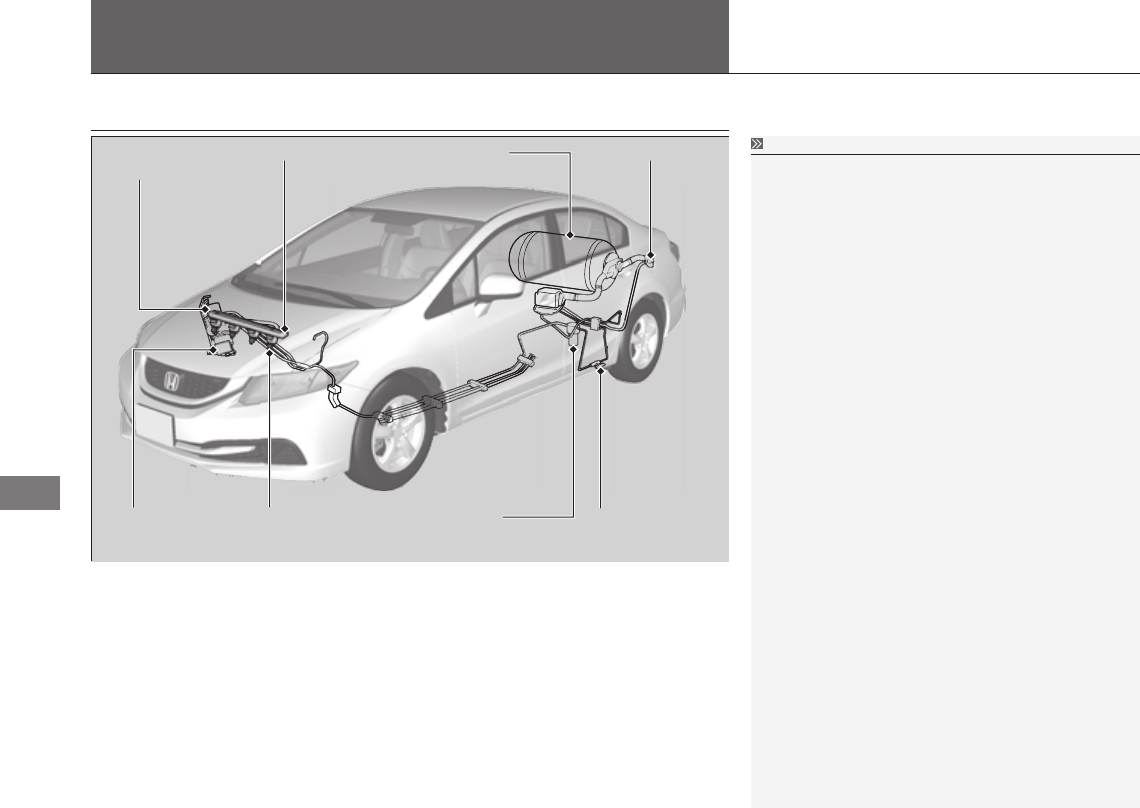
Fuel System
44
Information
System Components
Fuel Feed LineFuel Pressure
Regulator
Fuel Tank Fuel Receptacle
Fuel Filter
(Low Pressure)
Fuel Injector Fuel Filter
(High Pressure)
Manual Shut-Off
Valve
System Components
Your vehicle’s fuel system includes a fuel tank, a
fuel pressure regulator, a manual shut-off valve,
high pressure fuel lines, and other components that
comply with NFPA-52 standards.
The system in your vehicle, including the tank
and hoses, has been designed to hold gas at this
pressure. It has also been tested for safety. You
should never smell gas or hear a hissing sound
unless you are refueling.
Never modify or replace any original components or
parts with those specified for a gasoline vehicle.
Improper parts or components can damage your
vehicle’s fuel system and affect your vehicle’s safety
performance.
Unlike some gasoline models, your vehicle’s rear
seat-back cannot be folded down.
I
Home

45
Authorized Manuals
Information
Service Express
For electronic copies of service publications, you can purchase a subscription to
Service Express. Visit www.techinfo.honda.com for pricing and options.
Manuals in print
Manuals can be purchased from Helm Incorporated. You can order a manual by
phone at (800) 782-4356 (credit card orders only), or online at www.helminc.com.
I
Home
