Honda Bf115 Bzbd 1200001 1299999 Owners Manual
31ZW5602 Honda Marine – 4-Stroke Outboard Motors, Parts, Accessories, Financing | Official Site
2014-11-13
: Honda Honda-Bf115-Bzbd-1200001-1299999-Owners-Manual-108153 honda-bf115-bzbd-1200001-1299999-owners-manual-108153 honda pdf
Open the PDF directly: View PDF ![]() .
.
Page Count: 130 [warning: Documents this large are best viewed by clicking the View PDF Link!]
- COVER
- INTRODUCTION
- TYPES OF HONDA BF115A/130A OUTBOARD MOTORS
- CONTENTS
- OUTBOARD MOTOR SAFETY
- COMPONENT IDENTIFICATION
- CONTROLS & INSTRUMENTS
- PRE-OPERATION CHECKS
- STARTING THE ENGINE
- OPERATION
- STOPPING THE ENGINE
- TRANSPORTING
- CLEANING AND FLUSHING
- MAINTENANCE
- STORAGE/WINTERIZATION
- TROUBLESHOOTING
- SPECIFICATIONS
- WARRANTY SERVICE
- INDEX
- WIRING DIAGRAM
voirivsiiaa
IraNoH
California Proposition 65 Warning
WARNING: Engine Exhaust, some of its constituents, and certain vehicle components
contain or emit chemicals known to the State of California to cause cancer and birth
defects or other reproductive harm.
Keep this owner’s manual handy, so you can refer to it at any time. This owner’s manual
is considered a permanent part of the outboard motor and should remain with the outboard
motor if resold.
The information and specifications included in this publication were in effect at the time
of approval for printing. Honda Motor Co., Ltd. reserves the right, however, to discontinue
or change specifications or design at any time without notice and without incurring any
obligation whatever. No part of this publication may be reproduced without written
permission.
INTRODUCTION
Congratulations on your selection of
a Honda outboard motor. We are certain
you will be pleased with your purchase
of one of the finest outboard motors on
the market.
We want to help you get the best results
from your new outboard motor and to
operate it safely. This manual contains the
information on how to do that; please read
it carefully.
As you read this manual, you will
find information preceded by a
-1 symbol. That information is
intended to help you avoid damage to
your outboard motor, other property, or
the environment.
We suggest you read the warranty
policy to fully understand its coverage
and your responsibilities of ownership.
The warranty policy is a separate
document that should have been given
to you by your dealer.
When your outboard motor needs
scheduled maintenance, keep in mind that
your Honda marine dealer is specially
trained in servicing Honda outboard
motors. Your Honda marine dealer is
dedicated to your satisfaction and will be
pleased to answer your questions and
concerns.
0 2000 Honda Motor Co., Ltd.
All Right Reserved.
1
INTRODUCTION
A FEW WORDS ABOUT
SAFETY
Your safety and the safety of others are very
important. And using this outboard motor
safely is an important responsibility.
To help you make informed decisions
about safety, we have provided operating
procedures and other information on labels
and in this manual. This information alerts
you to potential hazards that could hurt
you or others.
Of course, it is not practical or possible
to warn, you about all the hazards
associated with operating or maintaining
an outboard motor. You must use your own
good judgment.
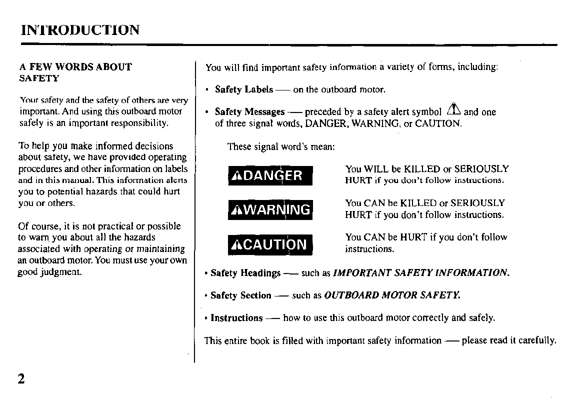
You will find important safety information a variety of forms, including:
l
Safety Labels - on the outboard motor.
l
Safety Messages - preceded by a safety alert symbol A and one
of three signal words, DANGER, WARNING, or CAUTION.
These signal word’s mean:
You WILL be KILLED or SERIOUSLY
HURT if you don’t follow instructions.
You CAN be KILLED or SERIOUSLY
HURT if you don’t follow instructions.
You CAN be HURT if you don’t follow
instructions.
l
Safety Headings - such as IMPORTANT SAFETY INFORMATION.
l
Safety Section - such as OUTBOARD MOTOR SAFETY.
l
Instructions - how to use this outboard motor correctly and safely.
This entire book is filled with important safety information - please read it carefully.
2
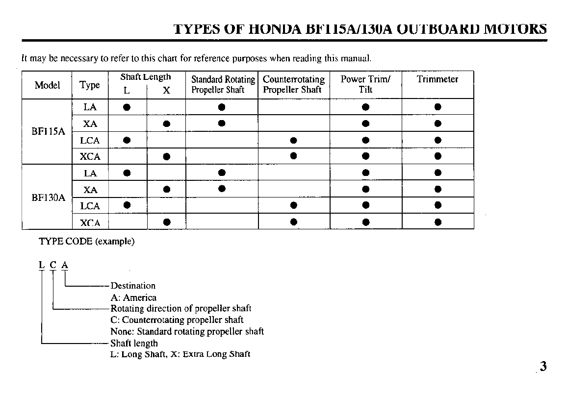
TYPES OF
HONDA BF115A/130A OUTBOARD MOTORS
It may be necessary to refer to this chart for reference purposes when reading this manual.
TYPE CODE (example)
I Destination
A: America
Rotating direction of propeller shaft
C: Counterrotating propeller shaft
None: Standard rotating propeller shaft
Shaft length
L: Long Shaft, X: Extra Long Shaft 3
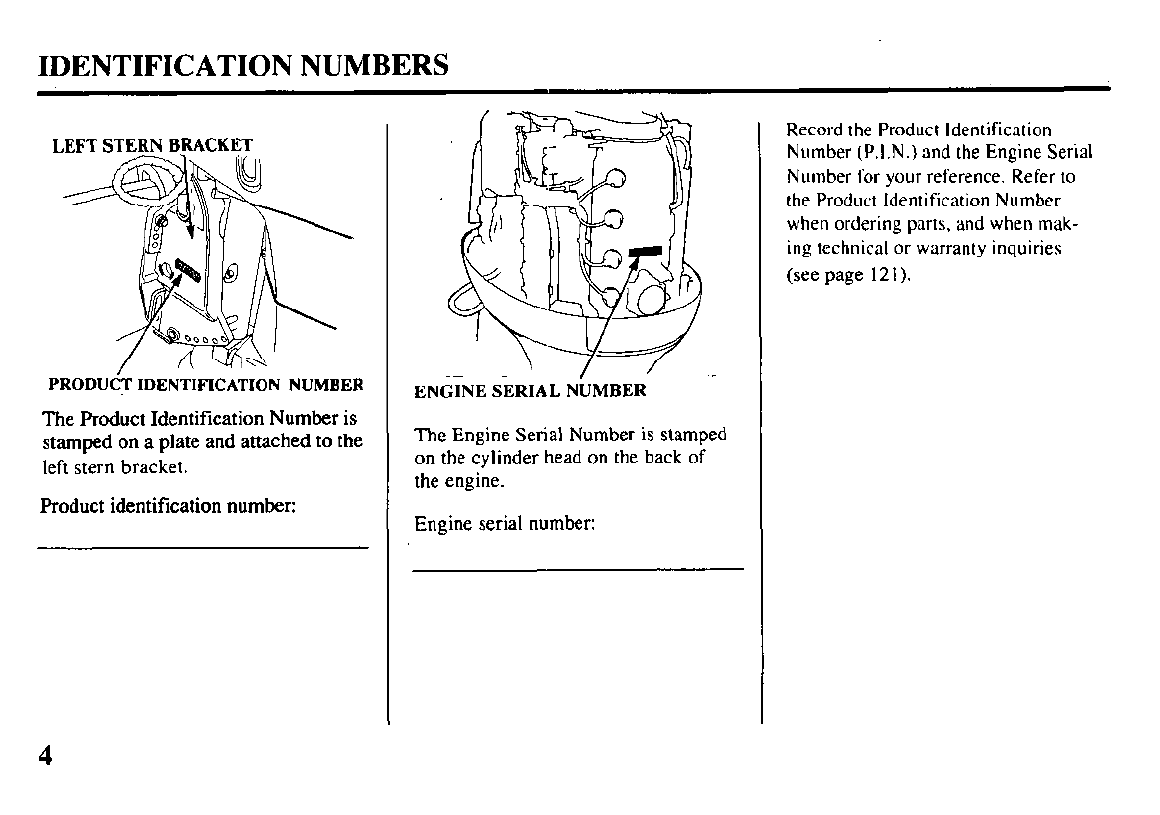
IDENTIFICATION NUMBERS
LEFT STERN BRACKET
PRODUdT
IDENTIFICATION NUMBER
The Product Identification Number is
stamped on a plate and attached to the
left stern bracket.
Product identification number:
The Engine Serial Number is stamped
on the cylinder head on the back of
the engine.
The Engine Serial Number is stamped
on the cylinder head on the back of
the engine.
Engine serial number: Engine serial number:
EN&NE SERIAL N:MBER’ -
Record the Product Identification
Number (P.I.N.) and the Engine Serial
Number for your reference. Refer to
the Product Identification Number
when ordering parts, and when mak-
ing technical or warranty inquiries
(see page 121).
4
CONTENTS
1. OUTBOARD MOTOR SAFETY
IMPORTANT SAFETY INFORMATION ,. 7
SAFETY LABEL LOCATIONS . . . . . 9
2. COMPONENT IDENTIFICATION . . 10
3. CONTROLS & INSTRUMENTS
SIDE-MOUNT TYPE
Remote Control Lever . . . . . . . . . . . . . 14
Neutral Release Lever . . . . . . . . . . . . . 15
Ignition Switch . . . . . . . . . . . . . . . . . . . . . . . . 15
Emergency Stop Switch Lanyard . 16
Fast Idle Lever . . . . . . . . . . . . . . . . . . . . . . . . . 17
Programmed Fuel Injection
(PGM-Fl) Indicator Light/Buzzer . . 17
Alternator (ACG) Indicator
Light/Buzzer . . . . . . . . . . . . . . . . . . . . . . . . . 18
Oil Pressure Indicator Light/Buzzer . . 18
Overheat Indicator Light/Buzzer . . . 18
Power Trim/Tilt Switch . . . . . . . . . . . 19
PANEL-MOUNT TYPE
Remote Control Lever . . . . . . . . . . . . . 20
Neutral Release Lever . . . . . . . . . . . . . 21
Ignition Switch . . . . . . . . . . . . . . . . . . . . . . . . 21
Emergency Stop Switch Lanyard . . 22
Throttle Button . . . . . . . . . . . . . . . . . . . . . . . . 23
Programmed Fuel Injection
(PGM-Fl) Indicator Light/Buzzer . . 23
Alternator (ACG) Indicator
Light/Buzzer . . . . . . . . . . . . . . . . . . . . . . . . . 23
Oil Pressure Indicator Light/Buzzer . . 24
Overheat Indicator Light/Buzzer . . . 24
Power Trim/Tilt Switch . . . . . . . . . . . 25
TOP-MOUNT TYPE
Remote Control Lever . . . . . . . . . . . . .
Ignition Switch . . . . . . . . . . . . . . . . . . . . . . . .
Emergency Stop Switch Lanyard . .
Throttle Button . . . . . . . . . . . . . . . . . . . . . . . .
Programmed Fuel Injection
@GM-FI) Indicator Light/Buzzer . .
Alternator (ACG) Indicator
Light/Buzzer . . . . . . . . . . . . . . . . . . . . . . . . .
Oil Pressure Indicator Light/Buzzer
Overheat Indicator Light/Buzzer . . .
Power Trim/Tilt Switch . . . . . . . . . . .
COMMON
Power Tilt Switch (engine pan) . .
Trim Meter . . . . . . . . . . . . . . . . . . . . . . . . . . . . . .
Manual Relief Valve . . . . . . . . . . . . . . .
Tilt Lock Lever . . . . . . . . . . . . . . . . . . . . . . . . . .
Trim Tab . . . . . . . . . . . . . . . . . . . . . . . . . . . . . . . . . .
Anodes . . . . . . . . . . . . . . . . . . . . . . . . . . . . . . . . . . . . .
Cooling System Indicator . . . . . . . . .
Water Intakes . . . . . . . . . . . . . . . . . . . . . . . . . . .
Transom Angle Adjusting Rod . . .
Fuel Cap/Gauge/Vent Knob
(optional fuel tank) . . . . .
Overrev Limiter . . . . . . . . . . . . . . . . . . . . . . .
Engine Cover Lock Lever . . . . . . .
Fuel Hose Connector . . . . . . . . . . . . . . .
4. PRE-OPERATION CHECKS
Engine Cover Removal/Installation . .
26
27
28
29
29
29
:i
31
32
32
33
34
35
36
36
36
37
38
38
39
39
40
Engine Oil ...............................
Fuel Level (optional fuel tank) . .
Fuel Recommendations ...........
Oxygenated Fuels ....................
Propeller/Cotter Pin
Inspection .............................
Control Lever Friction
Adjustment ...........................
Engine Cover Lock Lever
Adjustment ...........................
Other Checks
l
Fuel hose ...............................
l
Stern bracket .........................
l
Tool Kit.. ...............................
l
Anodes ..................................
5. STARTING THE ENGINE
Optional Fuel Tank.. ................
Fuel Line Connection ..............
STARTING THE ENGINE
(SIDE-MOUNT TYPE) ..........
(PANEL-MOUNT TYPE) ......
(TOP-MOUNT TYPE) ............
Troubleshooting Starting Problems..
6. OPERATION
Break-in Procedure ..................
SIDE-MOUNT TYPE
Gear Shifting ...........................
Cruising ...................................
PANEL-MOUNT TYPE
Gear Shifting ...........................
41
t3”
44
45
46
47
48
48
48
48
49
49
51
54
57
60
61
62
63
64
5
CONTENTS
Cruising ................................... 65
TOP-MOUNT TYPE
Gear Shifting ........................... 66
Crusing .................................... 67
POWER TRIM/TILT
Power Triflilt System .......... 68
Trim Meter .............................. 70
Power Tilt Switch (engine pan) . . 71
Manual Relief Valve ............... 7 1
Tilt Lock Lever.. ...................... 72
Trim Tab Adjustment .............. 73
MOTOR PROTECTION SYSTEM
Engine Oil Pressure, Overheat,
PGM-FI and ACG Indicator
Systems.. ................................ 74
Overrev Limiter.. ..................... 77
Anodes.. ................................... 77
Shallow Water Operation ........... 78
7. STOPPING THE ENGINE
(SIDE-MOUNT TYPE) .......... 79
(PANEL-MOUNT TYPE) ...... 80
(TOP-MOUNT TYPE). ........... 81
8. TRANSPORTING ..................... 82
9. CLEANING AND FLUSHING.. . 85
IO. MAINTENANCE.. ....................... 87
THE IMPORTANCE OF
MAINTENANCE.. .................. 87
MAINTENANCE SAFETY ...... 88
EMISSION CONTROL
SYSTEM INFORMATION .... 88
STAR LABEL ............................ 91
Tool Kit and Spare Parts ............ 93
MAINTENANCE SCHEDULE .... 94
Engine Oil ............................... 96
Oil Filter .................................. 99
Gear Oil ................................. 101
Spark Plugs ............................. 102
Battery (not included). ........... 103
Lubrication ............................ 105
Engine Fuel Filter.. .................. 106
Fuel Tank and Filter ................ 108
Fuse Replacement ................... 109
Propeller .................................. 1
1 1
Submerged Motor.. .................. 1 12
11. STORAGEWINTERIZATION . . 114
12. TROUBLESHOOTING ............. I 17
13. SPECIFICATIONS .................... 1 18
14. WARRANTY SERVICE ........... 121
15. INDEX ....................................... 122
16. WIRING DIAGRAM ................. 126
1. OUTBOARD MOTOR SAFETY
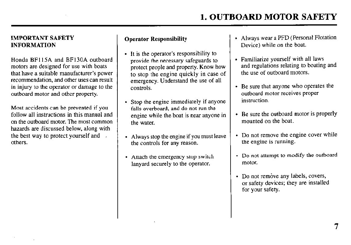
IMPORTANT SAFETY
INFORMATION
Honda BFl15A and BF130A outboard
motors are designed for use with boats
that have a suitable manufacturer’s power
recommendation, and other uses can result
in injury to the operator or damage to the
outboard motor and other property.
Most accidents can be prevented if you
follow all instructions in this manual and
on the outboard motor. The most common
hazards are discussed below, along with
the best way to protect yourself and
others.
Operator Responsibility
l
It is the operator’s responsibility to
provide the necessary safeguards to
protect people and property. Know how
to stop the engine quickly in case of
emergency. Understand the use of all
controls.
l
Stop the engine immediately if anyone
falls overboard, and do not run the
engine while the boat is near anyone in
the water.
l
Always stop the engine if you must leave
the controls for any reason.
l
Attach the emergency stop switch
lanyard securely to the operator.
l
Always wear a PFD (Personal Flotation
Device) while on the boat.
l
Familiarize yourself with all laws
and regulations relating to boating and
the use of outboard motors.
l
Be sure that anyone who operates the
outboard motor receives proper
instruction.
l
Be sure the outboard motor is properly
mounted on the boat.
l
Do not remove the engine cover while
the engine is running.
l
Do not attempt to modify the outboard
motor.
l
Do not remove any labels, covers,
or safety devices; they are installed
for your safety.
7
1. OUTBOARD MOTOR SAFETY
Refuel With Care
l
Gasoline is extremely
flammable, and gasoline vapor can
explode. Refuel outdoors, in a
well-ventilated area, with the engine
stopped. Never smoke near gasoline, and
keep other flames and sparks away.
l
Remove any portable fuel tank from the
boat for refueling. Keep the portable fuel
tank away from the battery or other
potential spark sources.
l
Refuel carefully to avoid spilling fuel.
Avoid overfilling the fuel tank.
l
After refueling, tighten the filler cap
securely. If any fuel is spilled, make sure
the area is dry before starting the engine.
8
Carbon Monoxide Hazard
Exhaust gas contains poisonous carbon
monoxide. Avoid inhalation of exhaust gas.
Never run the engine in a closed garage or
confined area.
1. OUTBOARD MOTOR SAFETY
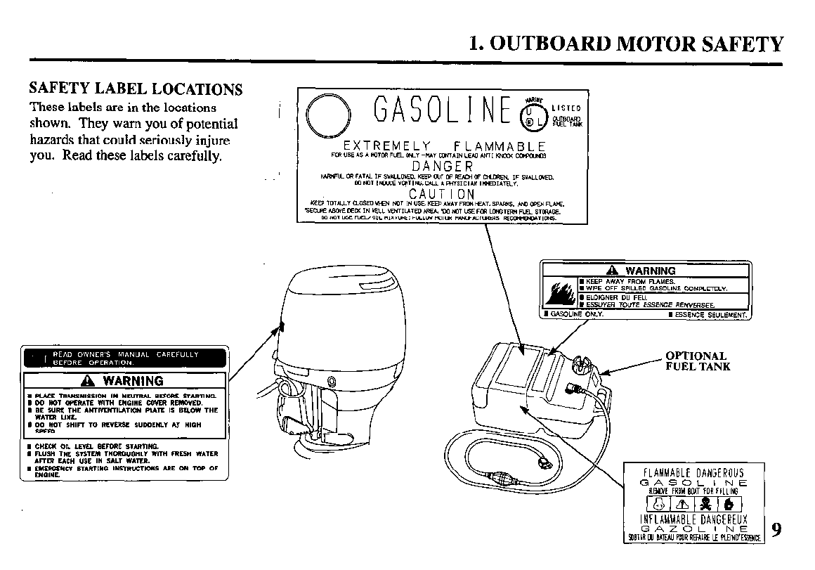
SAFETY LABEL LOCATIONS
These labels are in the locations
shown. They warn you of potential I
hazards that could seriously injure
you. Read these labels carefully.
FLAMMABLE
,
- -mFATbLIFsY*LLoyED.KEEPmn=~w~ IFsYN.LovEo.
mNor,NKE”arr,tJ3.w.
FUEL TANK
2. COMPONENT IDENTIFICATION
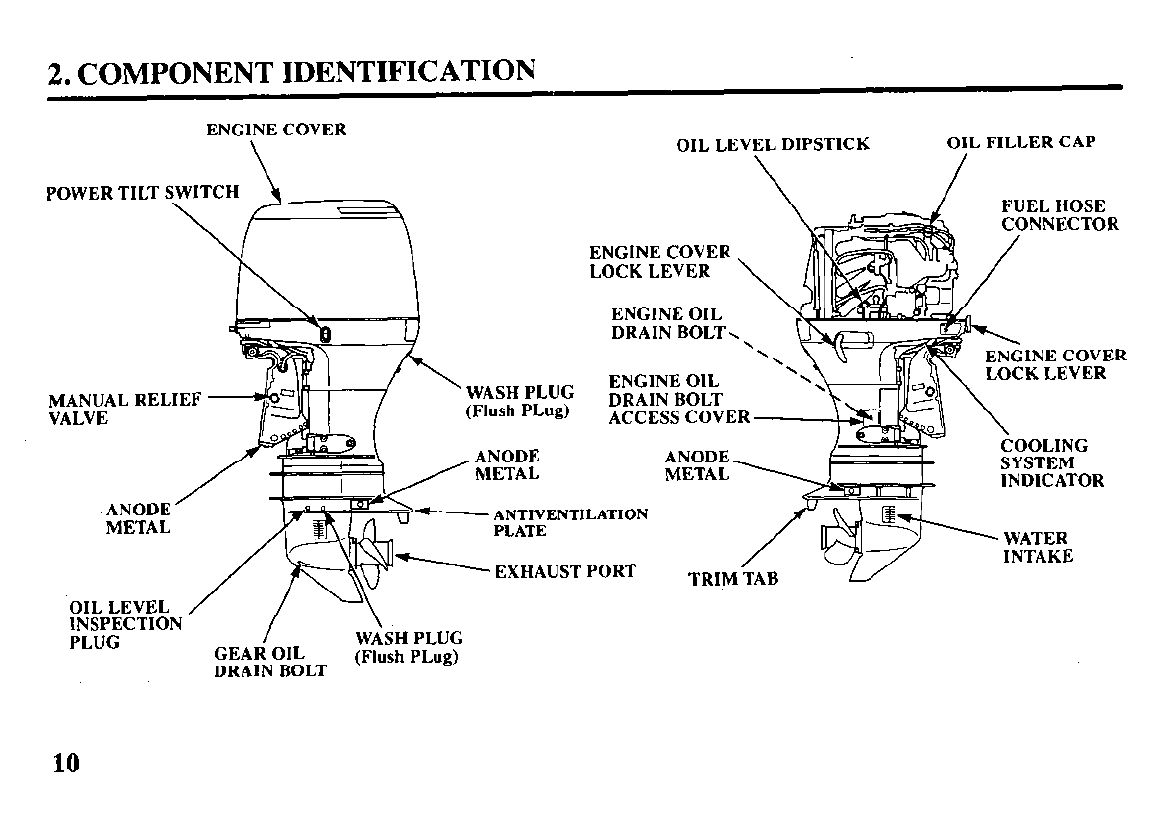
ENGINE COVER
\ OIL LEVEL DIPSTICK OIL FILLER CAP
POWER TILT SWITCH
\
ENGINE COVER
LOCK LEVER
EN&NE COVER
\ LOCK LEVER
ENGINE OIL
DRAIN BOLT \
ENGINE OIL
MANUAL
RELIEF DRAIN BOLT
VALVE ACCESS COVER
ANODE
METAL
ANTIVENTILATION
------- EXHAUST PORT
OIL LEVEL / I \
COOLING
SYSTEM
INl-llPATnP
INSPECTION / \.
PLUG WASH PLUG
GEAR OIL
DRAIN BOLT (Flush PLug)
10
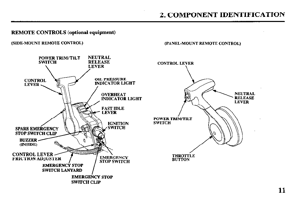
2. COMPONENT IDENTIFICATION
REMOTE CONTROLS (optional equipment)
(SIDE-MOUNT REMOTE CONTROL) (PANEL-MOUNT REMOTE CONTROL)
E;yT:RHTRIM/TILT
NEUTRAL
RELEASE
\ LEVER
/
L PRESSURE
DICATOR LIGHT
OVERHEAT
INDICATOR LIGHT
STOP SWITCH CL1
ITION
TCH
CONTROL LE
FRICTION AD
EMERGENCt’ STOP
SWITCH LANYARD I
EMERGENCY STOP
SWITCH CLIP
CONTROL LEVER
POWER TRI
SWITCH
THROTTLE
BUTTON
11
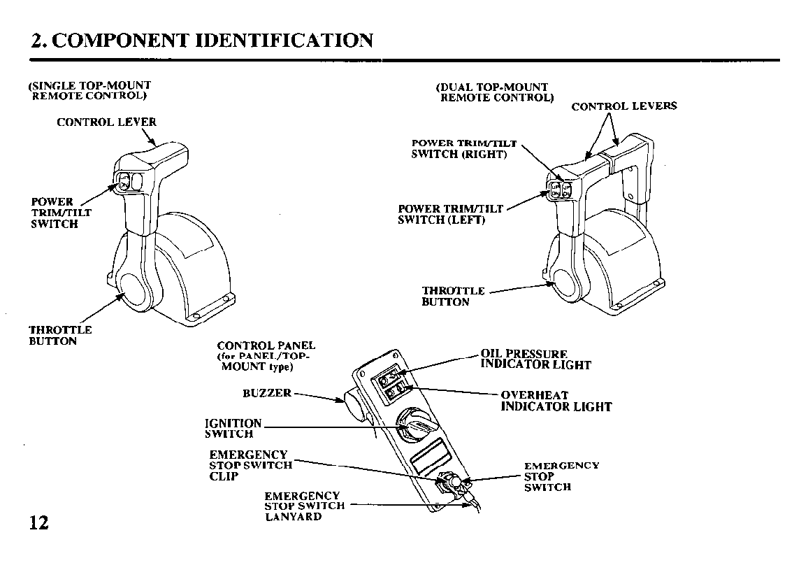
2. COMPONENT IDENTIFICATION
(SINGLE TOP-MOUNT
REMOTE CONTROL)
CONTROL LEVFR
BUTTON CONTROL PANEL
(for PANEL/TOP-
MOUNT type)
12
(DUAL TOP-MOUNT
REMOTE CONTROL) CONTROL LEVERS
POWER TRIM/TILT
SWITCH (RIGHT)
POWER TRIM/TILT
SWITCH (LEFT)
THROTTLE
BUTTON
iURE
IR LIGHT
INDICATOR LIGHT
EMERGENCY
STOP SWITCH EMERGENCY
CLIP * STOP
EMERGENCY SWITCH
STOP SWITCH
LANYARD uy/)
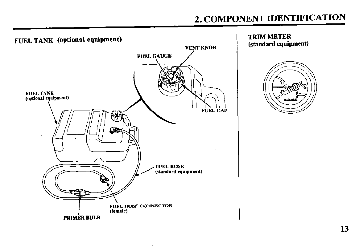
2. COMPONENT IDENTIFICATION
FUEL TANK (optional equipment)
VENT KNOB
FUEL TANK
(optional equipment)
(standard equipment)
I
\
FUEL HOSE CONNECTOR
(female)
PRIMER BULB
TRIM METER
(standard equipment)
13
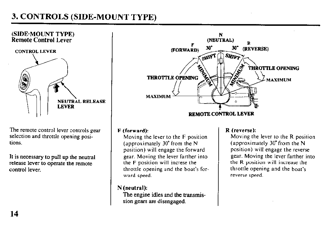
3. CONTROLS (SIDE-MOUNT TYPE)
(SIDE-MOUNT TYPE)
Remote Control Lever
The remote control lever controls gear
selection and throttle opening posi-
tions.
It is necessary to pull up the neutral
release lever to operate
the
remote
control lever.
MAXIMUM
REMOTE CONTROL LEVER
F (forward):
Moving the lever to the F position
(approximately 30” from the N
position) will engage the forward
gear. Moving the lever farther into
the F position will increse the
throttle opening and the boat’s for-
ward speed.
N (neutral):
The engine idles and the
transmis-
sion gears are disengaged.
R (reverse):
Moving the lever to the R position
(approximately 30” from the N
position) will engage the reverse
gear. Moving the lever farther into
the R position will increase the
throttle opening and the boat’s
reverse speed.
14
3. CONTROLS (SIDE-MOUNT TYPE)
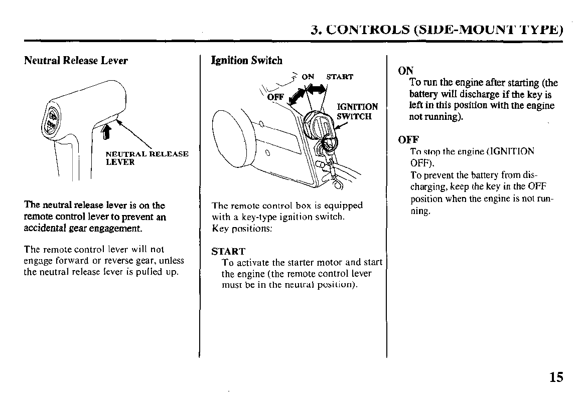
Neutral Release Lever
The neutral release lever is on the
remote control lever to prevent an
accidental gear engagement.
The remote control lever will not
engage forward or reverse gear, unless
the neutral release lever is pulled up.
Ignition Switch
+ ON START
ON
H
The remote control box is equipped
with a key-type ignition switch.
Key positions:
START
To activate the starter motor and start
the engine (the remote control lever
must be in the neutral position).
ON
To run
battery the engine after starting (the
will discharge if the kev is
left in-this position With the engine
not running).
OFF
To stop the engine (IGNITION
OFF).
To prevent the battery from dis-
charging, keep the key in the OFF
position when the engine is not run-
ning.
15
3. CONTROLS (SIDE-MOUNT TYPE)
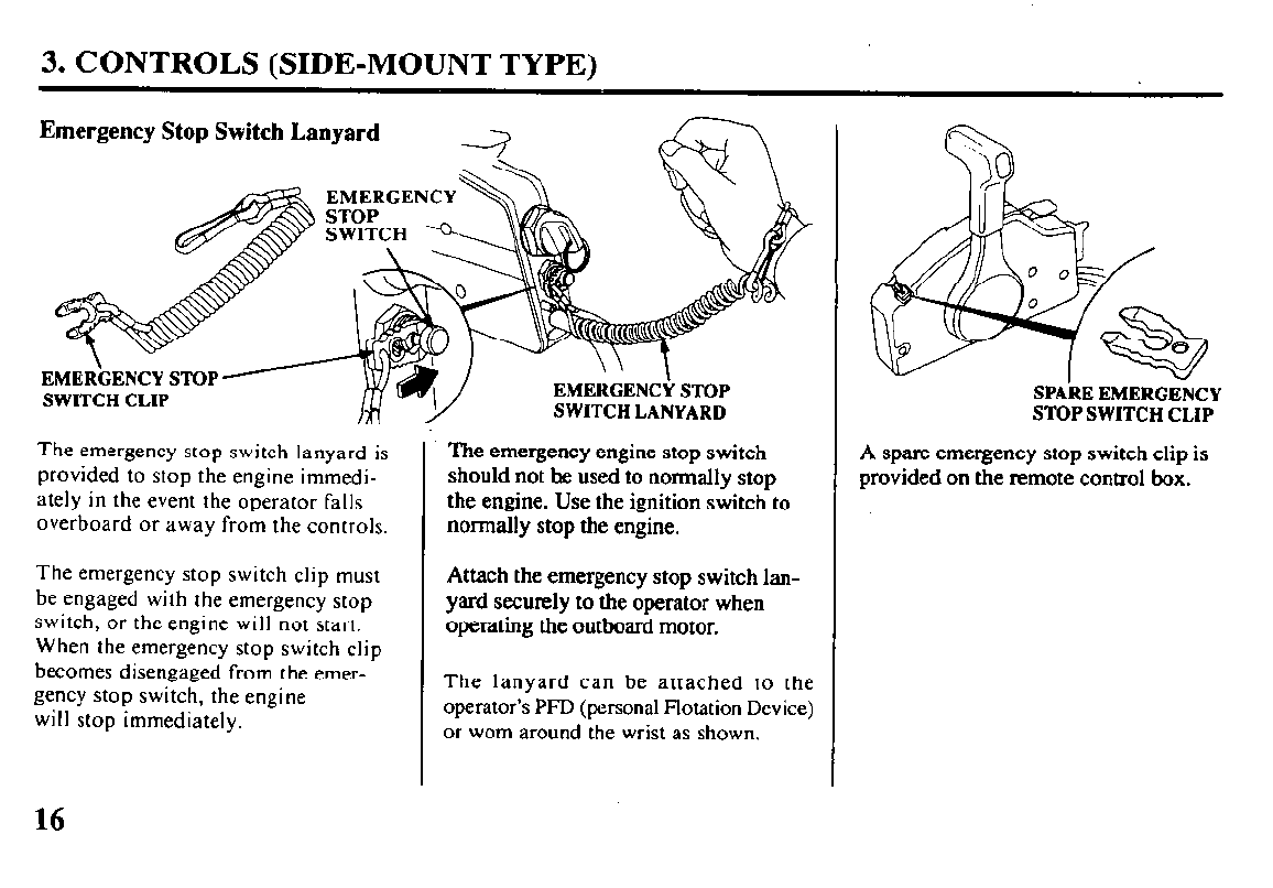
Emergency Stop Switch Lanyard
EMERGENCY
EMERGENCY STOP
Y
SWITCH LANYARD
The emergency stop switch lanyard is
provided to stop the engine immedi-
ately in the event the operator falls
overboard or away from the controls.
The emergency stop switch clip must
be engaged with the emergency stop
switch, or the engine will not start.
When the emergency stop switch clip
becomes disengaged from the emer-
gency stop switch, the engine
will stop immediately.
The emergency engine stop switch
should not he used to normally stop
the engine. Use the ignition switch to
normally stop the engine.
Attach the emergency stop switch lan-
yard securely to the operator when
operating the outboard motor.
The lanyard can be attached to the
operator’s PFD (personal Flotation Device)
or worn around the wrist as shown.
SPARE EMERGENCY
STOP SWITCH CLIP
A spare emergency stop switch clip is
provided on the remote control box.
16
. 3. CONTROLS (SIDE-MOUNT TYPE)
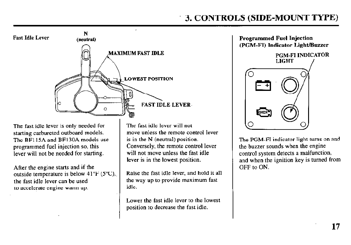
Fast Idle Lever N
(neutral)
A
AXIMUM FAST IDLE
LOWEST POSITION
LEI
The fast idle lever is only needed for
starting carbureted outboard models.
The BF115A and BFl30A models use
programmed fuel injection so, this
lever will not be needed for starting.
After the engine starts and if the
outside temperature is below 41 OF (YC),
the fast idle lever can be used
to accelerate engine warm up.
.EVER
The fast idle lever will not
move unless the remote control lever
is in the N (neutral) position.
Conversely, the remote control lever
will not move unless the fast idle
lever is in the lowest position.
Raise the fast idle lever, and hold it all
the way up to provide maximum fast
idle.
Lower the fast idle lever to the lowest
position to decrease the fast idle.
Programmed Fuel Injection
(PGM-FI) Indicator Light/Buzzer
PGM-FI
INDICATOR
LIGHT
/
The PGM-FI indicator light turns on and
the buzzer sounds when the engine
control system detects a malfunction,
and when the ignition key is turned from
OFF to ON.
17
3. CONTROLS (SIDE-MOUNT TYPE)
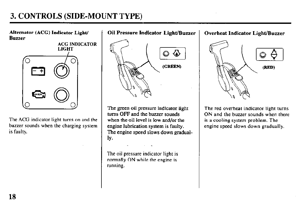
Alternator (ACG) Indicator
Light/
Buzzer
ACG INDICATOR
LIGHT
0 0
I
-+
: 0
6330
0
The ACG indicator light turns on and the
buzzer sounds when the charging system
is faulty.
Oil Pressure Indicator Light/Buzzer
The green oil pressure indicator light
turns OFF and the buzzer sounds
when the oil level is low and/or the
engine lubrication system is faulty.
The engine speed slows down gradual-
ly*
The oil pressure indicator light is
normally ON while the engine is
running.
Overheat Indicator Light/Buzzer
[a-]
(RED)
\
The red overheat indicator light turns
ON and the buzzer sounds when there
is a cooling system problem. The
engine speed slows down gradually.
3. CONTROLS (SIDE-MOUNT TYPE)
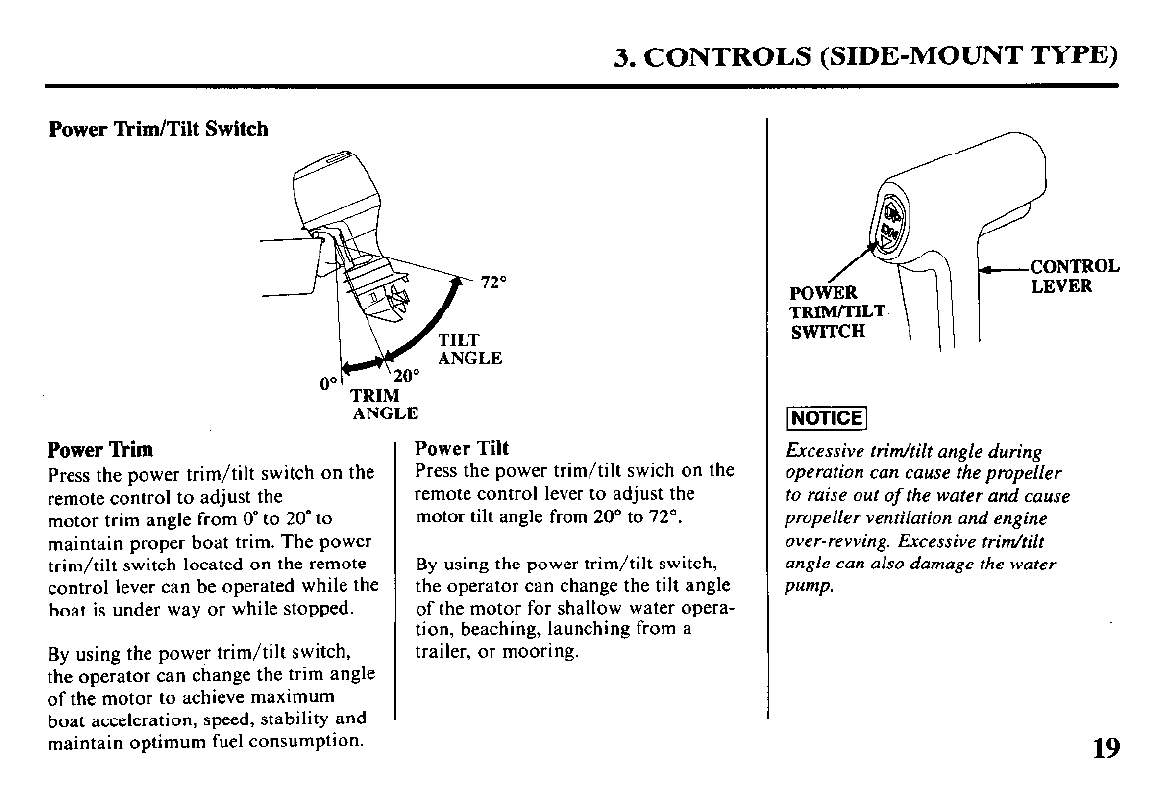
Power Rim/Tilt Switch
ANGLE
Power Tkim
Press the power trim/tilt switch on the
remote control to adjust the
motor trim angle from 0” to 20” to
maintain proper boat trim. The power
trim/tilt switch located on the remote
control lever can be operated while the
boat is under way or while stopped.
By using the power trim/tilt switch,
the operator can change the trim angle
of the motor to achieve maximum
boat acceleration, speed, stability and
maintain optimum fuel consumption.
Power Tilt
Press the power trim/tilt swich on the
remote control lever to adjust the
motor tilt angle from 20“ to 72’.
By using the power trim/tilt switch,
the operator can change the tilt angle
of the motor for shallow water opera-
tion, beaching, launching from a
trailer, or mooring.
Excessive trim/tilt angle during
operation can cause the propeller
to raise out
of
the water and cause
propeller ventilation and engine
over-revving. Excessive trim/tilt
angle can also damage the water
Pump.
19
3. CONTROLS (PANEL-MOUNT TYPE)
(PANEL-MOUNT TYPE)
Remote Control Lever
CONTROL LEVER
NEUTRAL RELEASE
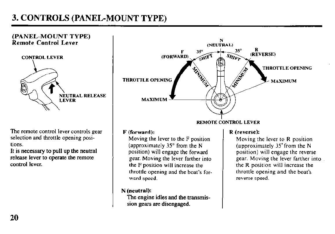
The remote control lever controls gear
selection and throttle opening posi-
tions.
It is necessary to
pull up the neutral
release lever to
operate the remote
control lever.
THROT
N
(NEUTRAL)
HROTTLE OPENING
TLE OPENING
MAXIMUM
REMOTE CONTROL LEVER
F (forward):
Moving the lever to the F position
(approximately 35” from the N
position) will engage the forward
gear. Moving the lever farther into
the F position will increase the
throttle opening and the boat’s for-
ward speed.
N (neutral):
The engine
idles and the transmis-
sion gears
are disengaged.
R (reverse):
Moving the lever to R position
(approximately 35” from the N
position) will engage the reverse
gear. Moving the lever farther into
the R position will increase the
throttle opening and the boat’s
reverse speed.
20
3. CONTROLS (PANEL-MOUNT TYPE)
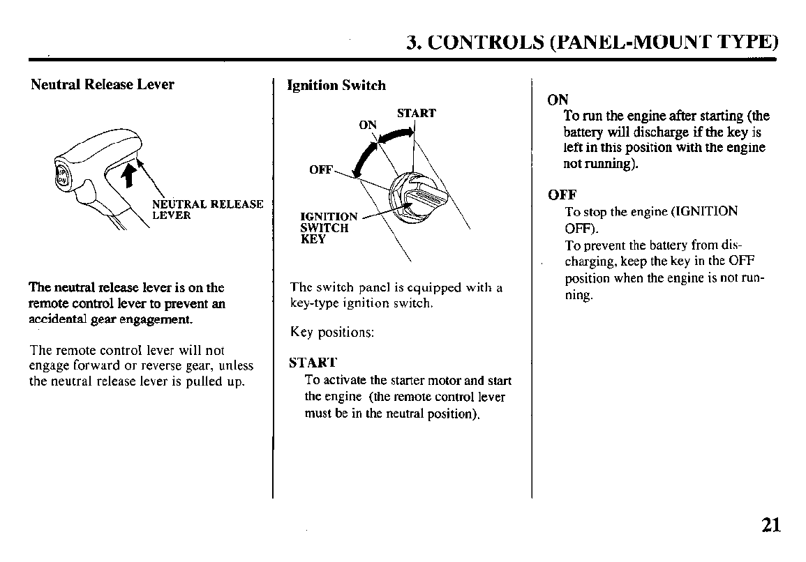
Neutral Release Lever
The neutral release lever is on the
remote control lever to prevent an
accidental gear engagement.
The remote control lever will not
engage forward or reverse gear, unless
the neutral release lever is pulled up.
Ignition Switch
START
The switch panel is equipped with a
key-type ignition switch.
Key positions:
START
To activate the starter motor and start
the engine (the remote control lever
must be in the neutral position).
ON
To run the engine after starting (the
battery will discharge if the key is
left in this position with the engine
not running).
OFF
To stop the engine (IGNITION
OFF).
To prevent the battery from dis-
charging, keep the key in the OFF
position when the engine is not run-
ning.
21
3. CONTROLS (PANEL-MOUNT TYPE)
Emergency Stop Switch Lanyard
EMERGENCY
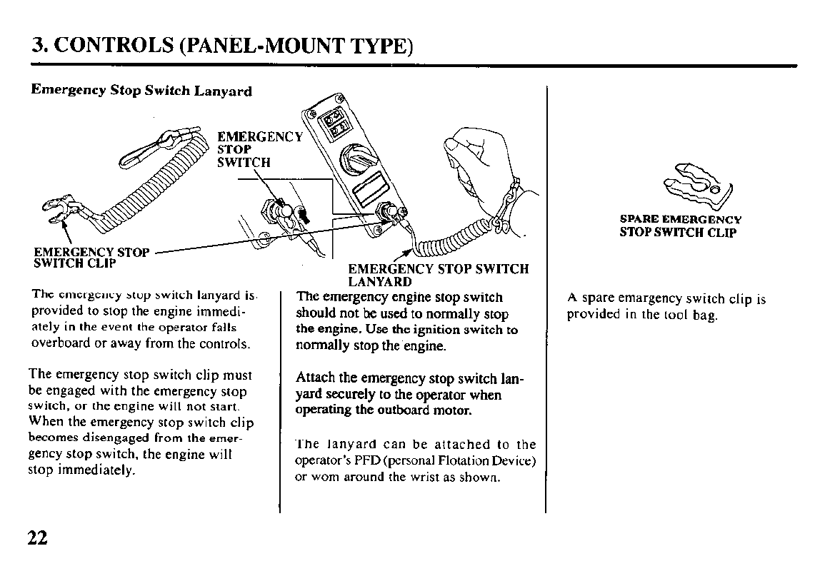
The emergency stop switch lanyard is
provided to stop the engine immedi-
ately in the event the operator falls
overboard or away from the controls.
The emergency stop switch clip must
be engaged with the emergency stop
switch, or the engine will not start.
When the emergency stop switch clip
becomes disengaged from the emer-
gency stop switch, the engine will
stop immediately.
EMERGENCY STOP SWITCH
LANYARD
The emergency engine stop switch
should not he used to normally stop
the engine. Use the ignition switch to
normally stop the engine.
Attach the emergency stop switch lan-
yard securely to the operator when
operating the outboard motor.
The lanyard can be attached to the
operator’s PFD (personal Flotation Device)
or worn around the wrist as shown.
SPARE EMERGENCY
STOP SWITCH CLIP
A spare emargency switch clip is
provided in the tool bag.
22
3. CONTROLS (PANEL-MOUNT TYPE)
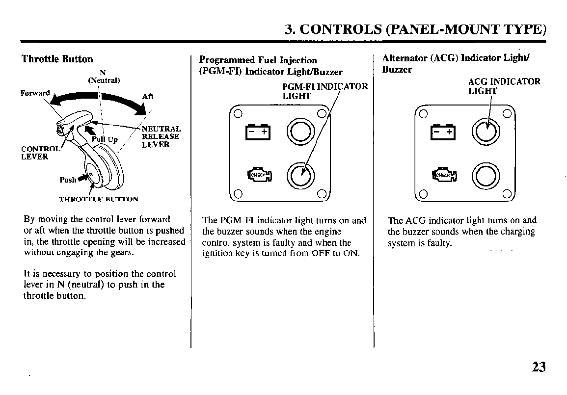
Throttle Button
N
(Neutral)
THROTTLE BUTTON
By moving the control lever forward
or aft when the throttle button is pushed
in, the throttle opening will be increased
without engaging the gears.
It is necessary to position the control
lever in N (neutral) to push in the
throttle button.
Programmed Fuel Injection
(PGM-FI) Indicator Light/Buzzer
PGM-FI INDICATOR
LIGHT
/
The PGM-FI indicator light turns on and
the buzzer sounds when the engine
control system is faulty and when the
ignition key is turned from OFF to ON.
Alternator (ACG) Indicator Light/
Buzzer
ACG INDICATOR
LIGHT
0 0
I
-+ CL
I
0
G3ao
0
The ACG indicator light turns on and
the buzzer sounds when the charging
system is faulty.
23
3. CONTROLS (PANEL-MOUNT TYPE)
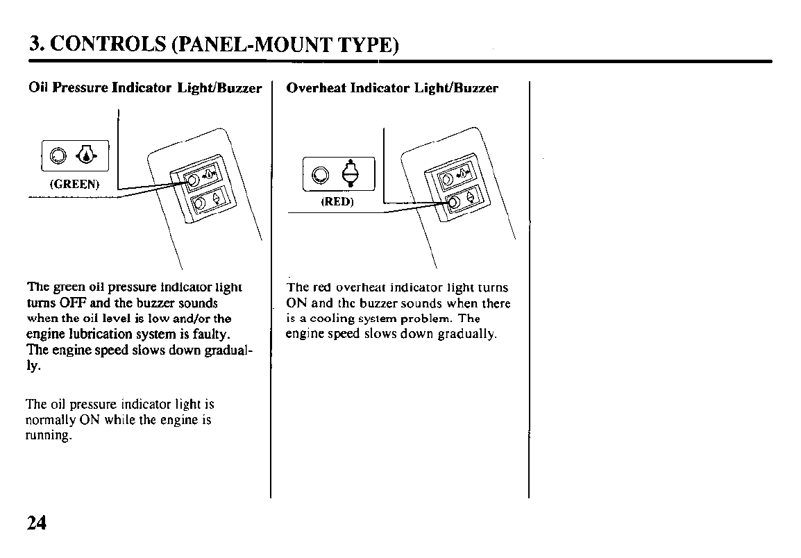
Oil Pressure Indicator Light/Buzzer
The green oil pressure indicator light
turns OFF and the buzzer sounds
when the oil level is low and/or the
engine lubrication system is faulty.
The engine speed slows down gradual-
ly*
The oil pressure indicator light is
normally ON while the engine is
running.
Overheat Indicator Light/Buzzer
\
The red overheat indicator light turns
ON and the buzzer sounds when there
is a cooling system problem. The
engine speed slows down gradually.
24
3. CONTROLS (PANEL-MOUNT TYPE)
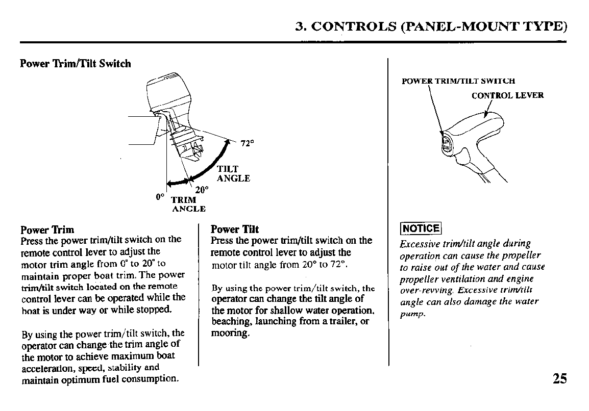
Power lkim/Tilt Switch
72”
LE
O” TRIM
ANGLE
Power Tkim
Press the power trim/tilt switch on the
remote control lever to adjust the
motor trim angle from 0” to 20” to
maintain proper boat trim. The power
trim/tilt switch located on the remote
control lever can be operated while the
boat is under way or while stopped.
By using the power trim/tilt switch, the
operator can change-the trim angle of
the motor to achieve maximum boat
acceleration, speed, stability and
maintain optimum fuel consumption.
Power Tilt
Press the power trim/tilt switch on the
remote control lever to adjust the
motor tilt angle from 20” to 72”.
By using the power trim/tilt switch, the
operator can change the tilt angle of
the motor for shallow water operation,
beaching, launching from a trailer, or
mooring.
POWER TRIM/TILT SWITCH
\ coN/TRoL LEVER
Excessive trim/tilt angle during
operation can cause the propeller
to raise out
of
the water and cause
propeller ventilation and engine
over-revving. Excessive trim/tilt
angle can also damage the water
pump.
25
3. CONTROLS (TOP-MOUNT TYPE)
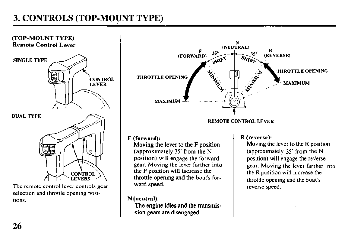
(TOP-MOUNT TYPE)
Remote Control Lever
SINGLE TYPE
CONTROL
DUAL TYPE
The remote control lever controls gear
selection and throttle opening posi-
tions.
THRO?
THROTTLE OPENING
TLE OPENING
MAXIMUM
t
REMOTE CONTROL LEVER
F (forward):
Moving the lever to the F position
(approximately 35’ from the N
position) will engage the forward
gear. Moving the lever farther into
the F position will increase the
throttle opening and the boat’s for-
ward speed.
N (neutral):
The engine idles and the transmis-
sion gears are disengaged.
R (reverse):
Moving the lever to the R position
(approximately 35” from the N
position) will engage the reverse
gear. Moving the lever farther into
the R position will increase the
throttle opening and the boat’s
reverse speed.
26
3. CONTROLS (TOP-MOUNT TYPE)
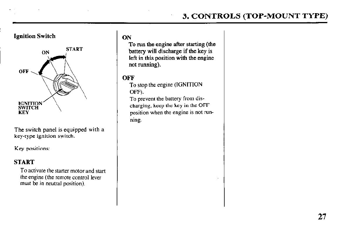
Ignition Switch
The switch panel is equipped with a
key-type ignition switch.
Key positions:
START
To activate the starter motor and start
the engine (the remote control lever
must be in neutral position).
ON
To run the engine after starting (the
battery will discharge if the key is
left in this position with the engine
not running).
OFF
To stop the engine (IGNITION
OFF).
To prevent the
battery
from dis-
charging, keep the key in the OFF
position when the engine is not run-
ning.
27
3. CONTROLS (TOP-MOUNT TYPE)
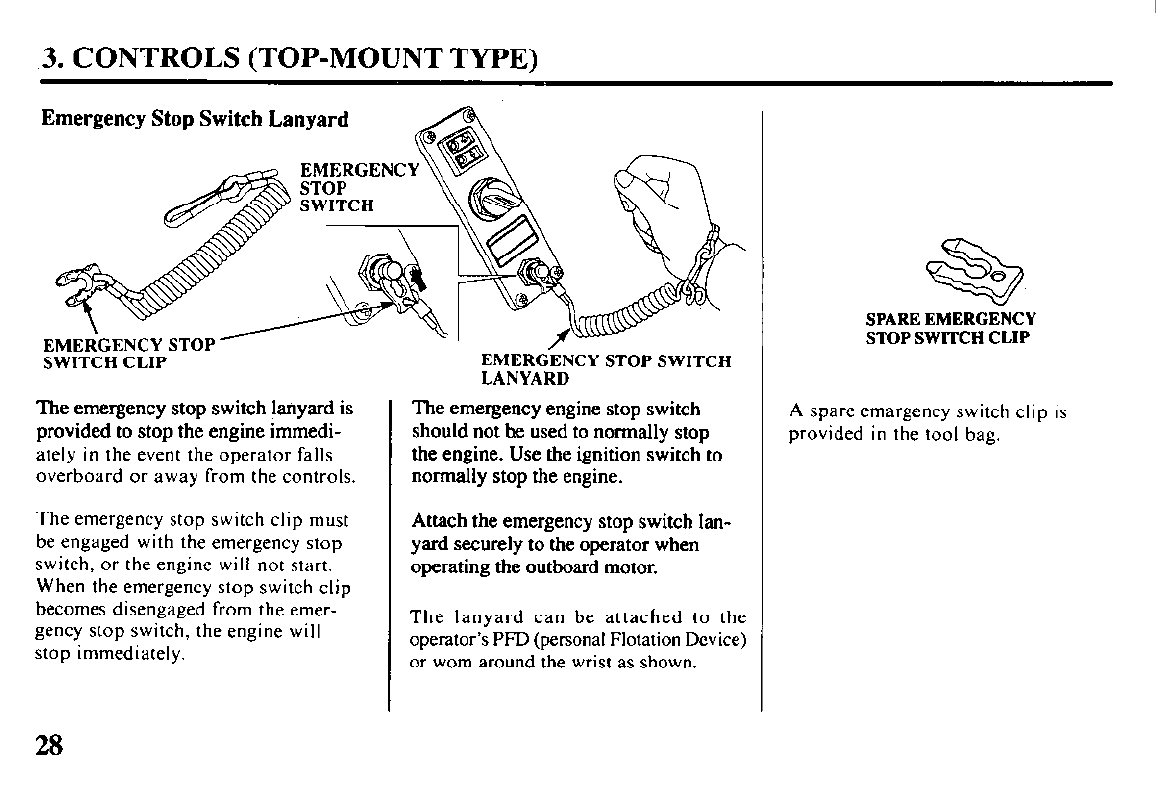
Emergency Stop Switch Lanyard
EMEliGENCY STOP y
SWITCH CLIP
The emergency stop switch @yard is
provided to stop the engine immedi-
ately in the event the operator falls
overboard or away from the controls.
The emergency stop switch clip must
be engaged with the emergency stop
switch, or the engine will not start.
When the emergency stop switch clip
becomes disengaged from the emer-
gency stop switch, the engine will
stop immediately.
EMERtiENCY STOP SWITCH
LANYARD
The emergency engine stop switch
should not be used to normally stop
the engine. Use the ignition switch to
normally
stop the engine.
Attach the emergency stop switch lan-
yard securely to the operator when
operating the outboard motor.
The lanyard can be attached to the
operator’s PFD (personal Flotation Device)
or worn around the wrist as shown.
SPARE EMERGENCY
STOP SWITCH CLIP
A spare emargency switch clip is
provided in the tool bag.
28
3. CONTROLS (TOP-MOUNT TYPE)
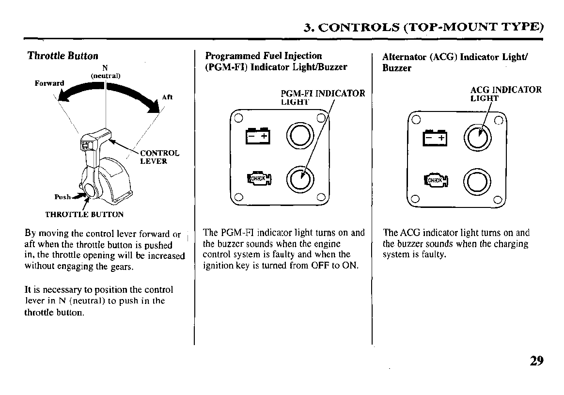
Throttle Button
CONTROL
LEVER
Push
THROTTiE BUTTON
By moving the control lever forward or ,
aft when the throttle button is pushed
in, the throttle opening will be increased
without engaging the gears.
It
is necessary to position the control
lever in N (neutral) to push in the
throttle button.
Programmed Fuel Injection
(PGM-FI) Indicator Light/Buzzer
0
PGM-FI INDIC
LIGHT / ATOR
7
0
d
0
The PGM-FI indicator light turns on and
the buzzer sounds when the engine
control system is faulty and when the
ignition key is turned from OFF to ON.
Alternator (ACG) Indicator Light/
Buzzer
;fCZH+DICATOR
0 0
ml
I
-+
The ACG indicator light turns on and
the buzzer sounds when the charging
system is faulty.
29
3. CONTROLS (TOP-MOUNT TYPE)
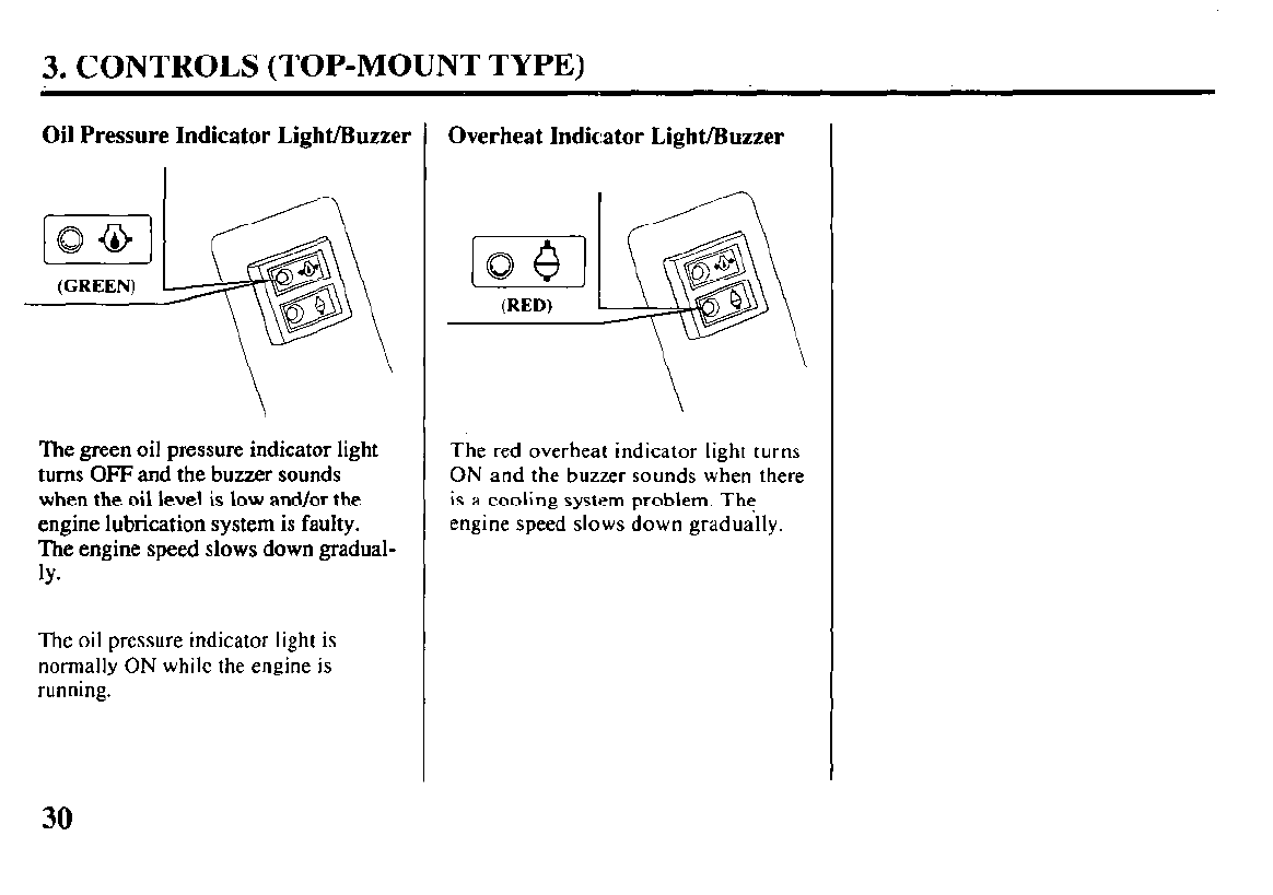
Oil Pressure Indicator Light/Buzzer
[-ST-]
(GREEN)
The green oil pressure indicator light
turns OFF and the buzzer sounds
when the oil ievel is low and/or the
engine lubrication system is faulty.
The engine speed slows down gradual-
ly*
The oil pressure indicator light is
normally ON while the engine is
running.
Overheat Indicator Light/Buzzer
\
The red overheat indicator light turns
ON and the buzzer sounds when there
is a cooling system problem. The
engine speed slows down gradually.
30
3. CONTROLS (TOP-MOUNT TYPE)
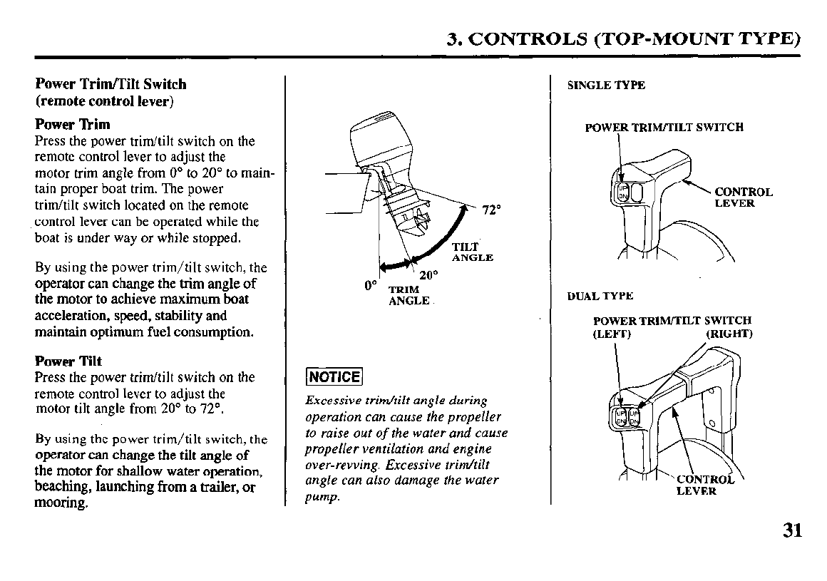
Power Trim/Tilt Switch
(remote control lever)
Power Tkim
Press the power trim/tilt switch on the
remote control lever to adjust the
motor trim angle from 0’ to 20’ to main-
tain proper boat trim. The power
trim/tilt switch located on the remote
control lever can be operated while the
boat is under way or while stopped.
By using the power trim/tilt switch, the
operator can change the trim angle of
the motor to achieve maximum boat
acceleration, speed, stability and
maintain optimum fuel consumption.
Power Tilt
Press the power trim/tilt switch on the
remote control lever to adjust the
motor tilt angle from 20’ to 72’.
By using the power trim/tilt switch, the
operator can change the tilt angle of
the motor for shallow water operation,
beaching, launching from a trailer, or
mooring.
0"
TRIM
ANGLE.
Excessive trir&ilt angle during
operation can cause the propeller
to raise out
of
the water and
cause
propeller ventilation and engine
over-revving. Excessive trim/tilt
angle can also damage the water
pump.
SINGLE TYPE
POWER TRIM/TILT SWITCH
DUAL TYPE
POWER TRIM/TILT SWITCH
WEI-3 (RIGHT)
LEVER
31
3. CONTROLS (COMMON)
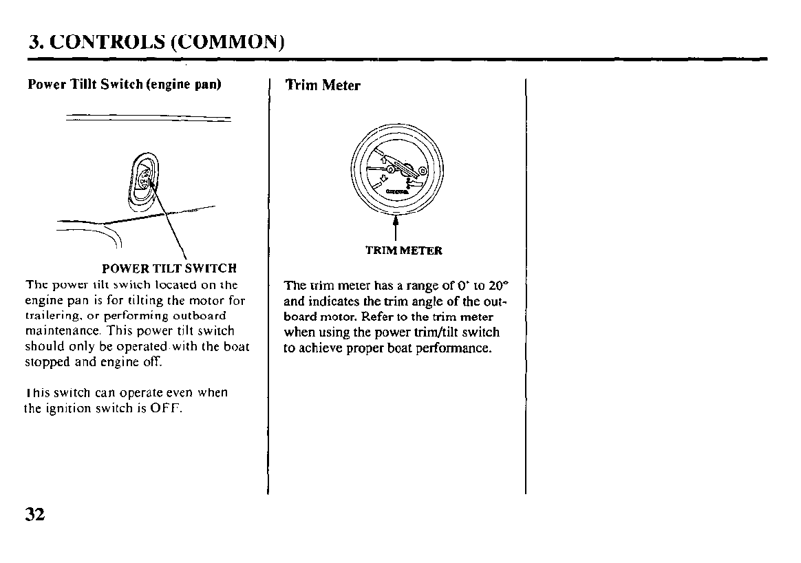
Power Tillt Switch (engine pan)
POWER TILT SWITCH
The power tilt switch located on the
engine pan is for tilting the motor for
trailering, or performing outboard
maintenance. This power tilt switch
should only be operated with the boat
stopped and engine off.
This switch can operate even when
the ignition switch is OFF.
Trim Meter
TRIM METER
The trim meter
has a range of 0” to 20”
and indicates the trim angle of the out-
board motor. Refer to the trim meter
when using the power trim/tilt switch
to achieve proper boat performance.
32
3. CONTRGLS (COMMON)
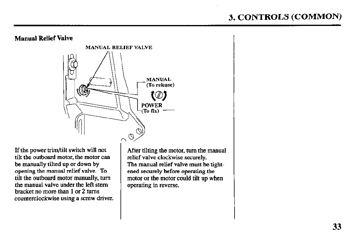
Manual Relief Valve
MANUAL RELIEF VALVE
If the power trim/tilt switch will not
tilt the outboard motor, the motor can
be manually tilted up or down by
opening the manual relief valve. To
tilt the outboard motor manually, turn
the manual valve under the left stem
bracket no more than 1 or 2 turns
counterclockwise using a screw driver.
After tilting the motor, turn the manual
relief valve clockwise securely.
The manual relief valve must be tight-
ened securely before operating the
motor or the motor could tilt up when
operating in reverse.
33
3. CONTROLS (COMMON)
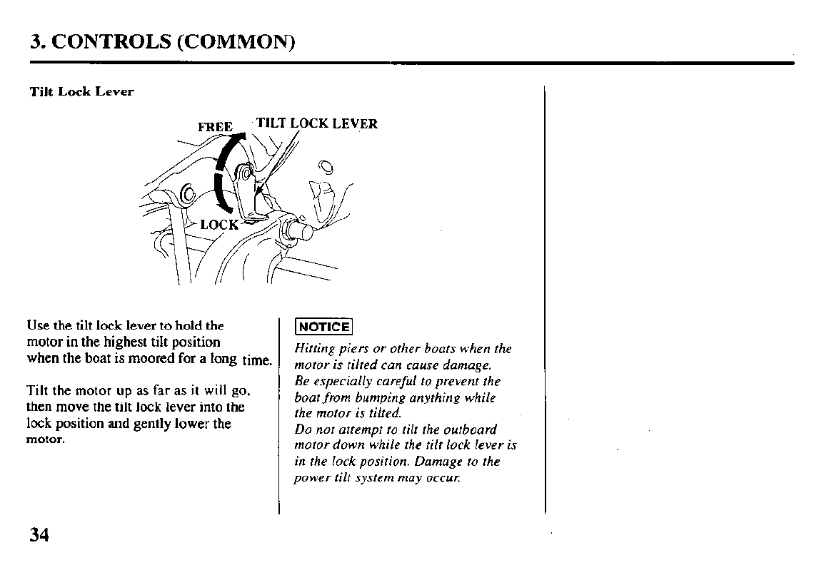
Tilt Lock Lever
TILT LOCK LEVER
Use the tilt lock lever to hold the
motor in the highest tilt position
when the boat is moored for a long time.
Tilt the motor
up
as far as it will go,
then move the tilt lock lever into the
lock position and gently lower the
motor.
Hitting piers or other boats when the
motor is tilted can cause damage.
Be especially careful to prevent the
boat from bumping anything while
the motor is tilted.
Do not attempt to tilt the outboard
motor down while the tilt lock lever is
in the lock position. Damage to the
power tilt system may occur
34
3. CONTROLS (COMMON)
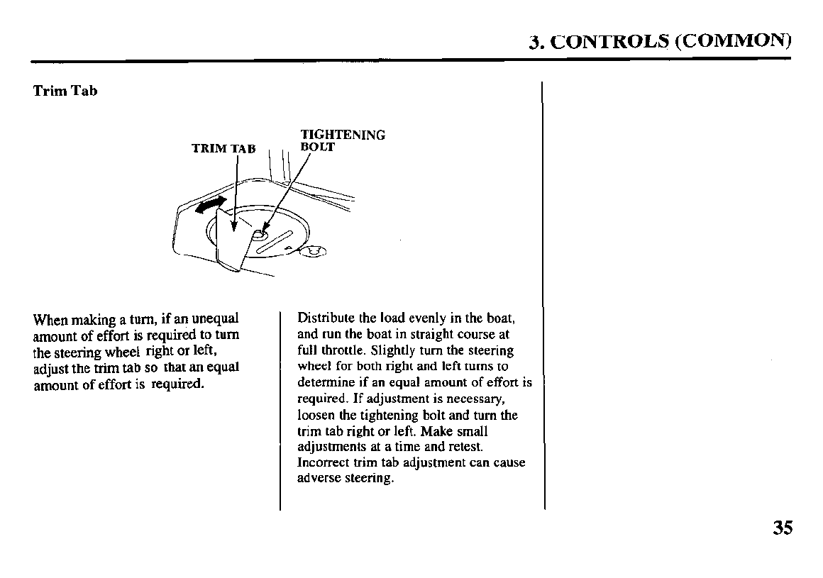
Trim Tab
TIGHTENING
When making a turn, if an unequal
amount of effort is required to turn
the steering wheel right
or left,
adjust the trim tab so that an equal
amount of effort is required.
Distribute the load evenly in the boat,
and run the boat in straight course at
full throttle. Slightly turn the steering
wheel for both right and left turns to
determine if an equal amount of effort is
required. If adjustment is necessary,
loosen the tightening bolt and turn the
trim tab right or left. Make small
adjustments at a time and retest.
Incorrect trim tab adjustment can cause
adverse steering.
35
3. CONTROLS (COMMON)
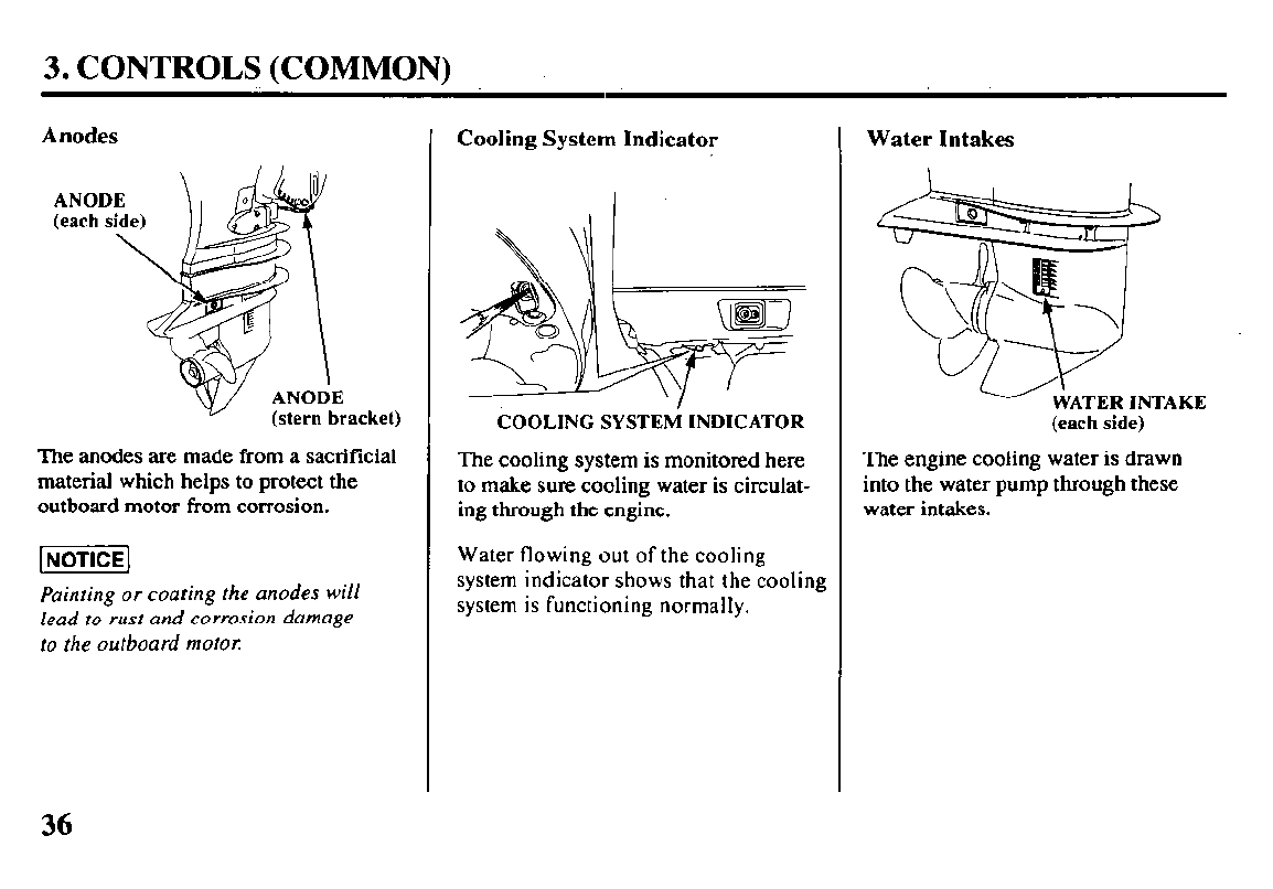
Anodes
acket)
The anodes are made from a sacrificial
material which helps to protect the
outboard motor from corrosion.
Painting or coating the anodes will
lead to rust and corrosion damage
to the outboard motel:
Cooling System Indicator
COOLING SYSTEM
INDICATOR
The cooling system is monitored here
to make sure cooling water is circulat-
ing through the engine.
Water flowing out of the cooling
system
indicator shows that the cooling
system is functioning normally.
Water Intakes
(each side)
The engine cooling water is drawn
into the water pump through these
water intakes.
36
3. CONTROLS (COMMON)
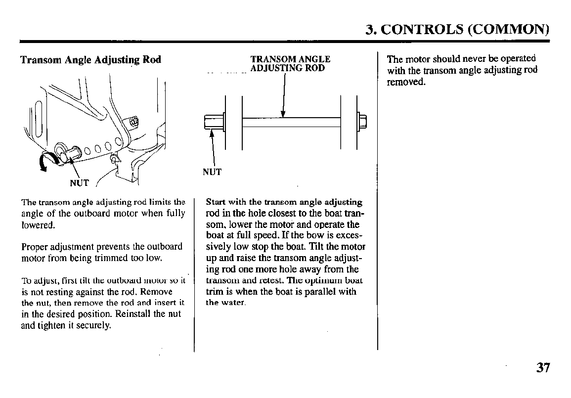
Transom Angle Adjusting Rod
The transom angle adjusting rod limits the
angle of the outboard motor when fully
lowered.
Proper adjustment prevents the outboard
motor from being trimmed too low.
To adjust, first tilt the outboard motor so it ’
is not resting against the rod. Remove
the nut, then remove the rod and insert it
in the desired position. Reinstall the nut
and tighten it securely.
TRANSOM ANGLE
ADJUSTING ROD
I
NtiT
Start with the transom angle adjusting
rod in the hole closest to the boat tran-
som, lower the motor and operate the
boat at full speed. If the bow is exces-
sively low stop the boat. Tilt the motor
up and raise the transom angle adjust-
ing rod one more hole away from the
transom and retest. The optimum boat
trim is when the boat is parallel with
the water.
The motor should never be operated
with the transom angle adjusting rod
removed.
3. CONTROLS (COMMON)
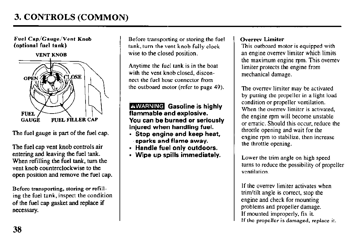
Fuel Cap/Gauge/Vent Knob
Before transporting or storing the fuel
(optional fuel tank) tank, turn the vent knob fully clock-
VENT KNOB
wise to the closed position.
GAUGh FUEL F’kLER CAP
The fuel gauge is part of the fuel cap.
The fuel
cap vent knob controls air
entering and leaving the fuel tank.
When refilling the fuel tank, turn the
vent knob counterclockwise to the
open position
and remove the
fuel cap.
Before transporting, storing or refill-
ing the fuel tank, inspect the condition
of the fuel cap gasket and replace if
necessary.
Anytime the fuel tank is in the boat
with the vent knob closed, discon-
nect the fuel hose connector from
the outboard motor (refer to page 49).
m Gasoline is highly
. -
flammable and explosive.
You can be burned or seriously
injured when handling fuel.
l
Stop engine and keep heat,
sparks and flame away.
. Handle fuel only outdoors.
l
Wipe up spills immediately.
Overrev Limiter
This outboard motor is equipped with
an engine overrev limiter which limits
the maximum engine rpm. This overrev
limiter protects the engine from
mechanical damage.
The ovcrrcv limiter may be activated
by putting the propeller in a light load
condition or propeller ventilation.
When the overrev limiter is activated,
the engine rpm will become unstable
or erratic. Should this occur, reduce the
throttle opening and wait for the
engine rpm to stabilize, then increase
the throttle opening.
Lower the trim angle on high speed
turns to reduce the possibility of propeller
ventilation.
If the overrev limiter activates when
trim/tilt angle is correct, stop the
engine and check for mounting
problems and propeller damage.
If mounted improperly, fix it.
If the propeller is damaged, replace it.
38
3. CONTROLS (COMMON)
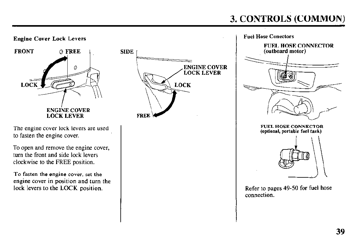
Engine Cover Lock Levers
FRONT 0 FREE (
ENGINE COVER
LOCK LEVER
The engine cover lock levers are used
to fasten the engine cover.
To open and remove the engine cover,
turn the front and side lock levers
clockwise to the FREE position.
To
fasten the engine cover, set the
engine cover in position and turn the
lock levers to the LOCK position.
SIDE 1
ENGINE COVER
LOCK LEVER
Fuel Hose Conectors
FUEL HOSE CONNECTOR
(outboard motor)
FUEL HOSE CONNECTOR
(optional, portable fuel tank)
i\
./\
Refer to pages 49-50 for fuel hose
connection.
39
4. PRE-OPERATION CHECKS
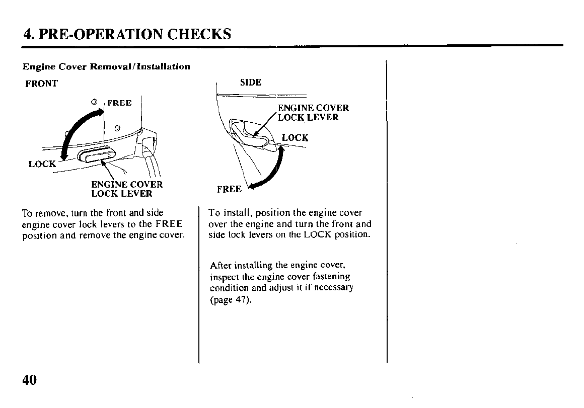
Engine Cover Removal/Installation
FRONT
0
,FREE I
ENGINECOVER
LOCKLEVER
To remove, turn the front and side
engine cover lock levers to the FREE
position and remove the engine cover.
To install, position the engine cover
over the engine and turn the front and
side lock levers on the LOCK position.
After installing the engine cover,
inspect the engine cover fastening
condition and adjust it if necessary
(page 47).
40
4. PRE-OPERATION CHECKS
Engine Oil
Engine oil is a major factor affecting
engine performance and service life.
INOTICE]
Running the engine with insufficient
oil can cause serious engine damage.
Recommended oil: SAE low-30
Use 4-stroke motor oil that meets or
exceeds the requirements for API
service classification SG or SH.
Always check the API SERVICE
label on the oil container to be sure it
includes the letters SC or SH.
Using nondetergent oil can shorten
the engine’s service life, and using
2-stroke oil can damage the engine.
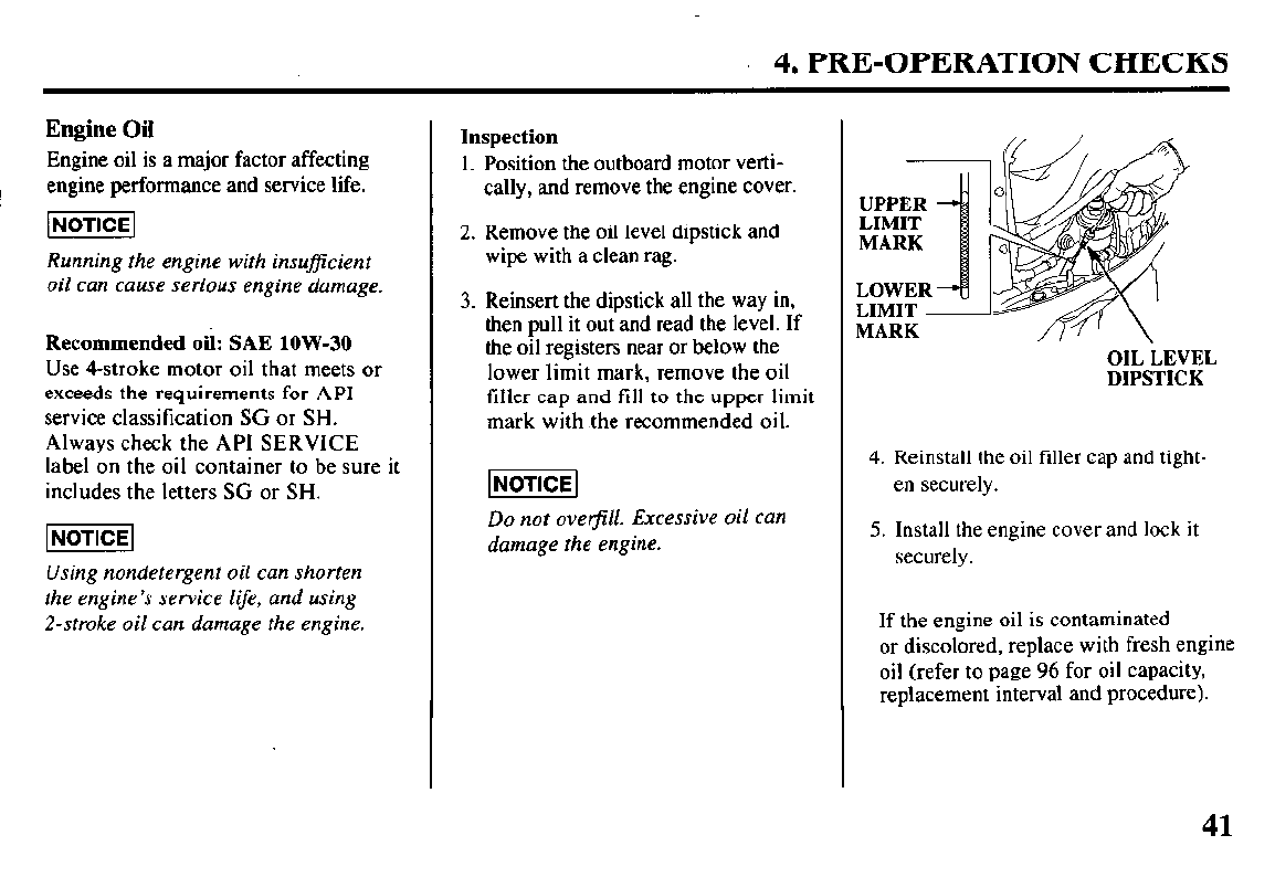
Inspection
1. Position the outboard motor verti-
cally, and remove the engine cover.
2. Remove the oil level dipstick and
wipe with a clean rag.
3. Reinsert the dipstick all the way in,
then pull it out and read the level. If
the oil registers near or below the
lower limit mark, remove the oil
tiller cap and fill to the upper limit
mark with .the recommended oil.
Do not overjill. Excessive oil can
damage the engine.
MARK
OIL LEVEL
DIPSTICK
4. Reinstall the oil filler cap and tight-
en securely.
5. Install the engine cover and lock it
securely.
If the engine oil is contaminated
or discolored, replace with fresh engine
oil (refer to page 96 for oil capacity,
replacement interval and procedure).
41
4. PRE-OPERATION CHECKS
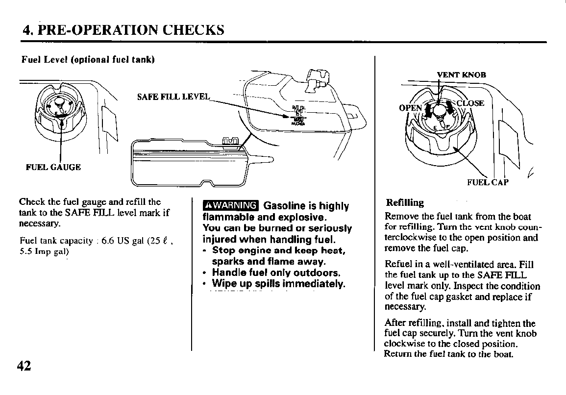
Fuel Level (optional fuel tank)
FUEL GAUGE
Check the fuel gauge and refill the
tank to the SAFE FILL level mark if
necessary.
Fuel tank capacity : 6.6 US gal (25 e ,
5.5 Imp gal)
42
m Gasoline is highly
flammable and explosive. -
You can be burned or seriously
injured when handling fuel.
l
Stop engine and keep heat,
sparks and flame away.
l
Handle fuel only outdoors.
l
Wipe up spills immediately.
VENT KNOB
\
:
,C FUEi
b
I L
AP
Refilling
Remove the fuel tank
from
the boat
for refilling.
Turn the vent knob coun-
terclockwise to the open position and
remove the fuel cap.
Refuel in a well-ventilated area. Fill
the fuel tank up to the SAFE! FILL
level mark only. Inspect the condition
of the fuel cap gasket and replace if
necessary.
After refilling, install and tighten the
fuel cap securely. Turn the vent knob
clockwise to the closed position.
Return the fuel tank to the boat.
4. PRE-OPERATION CHECKS
Fuel Recommendations
Use unleaded gasoline with a pqmp octane rating of 86
or higher.
These outboard motors are certified to operate on
unleaded gasoline. Unleaded gasoline produces fewer
engine and spark plug deposits and extends exhaust
system life.
Never use stale or contaminated gasoline or an oil/gaso-
line mixture. Avoid getting dirt or water in the fuel tank.
Occasionally you may hear light “spark knock” or “ping-
ing” (metallic rapping noise) while operating under heavy
loads. This is no cause for concern.
If spark knock or pinging occurs at a steady engine speed,
under normal load, change brands of gasoline. If spark
knock or pinging persists, see an authorized Honda Ma-
rine dealer.
(NOTICE1
Running the engine with persistent spark knock or
pinging can cause engine damage.
Running the engine with persistent spark knock or ping-
ing is misuse, and the Distributor’s Limited Warranty
does not cover parts damaged by misuse.
43
4. PRE-OPERATION CHECKS
Oxygena ted Fuels
Some conventional gasolines are being blended with alco-
hol or an ether compound. These gasolines are collec-
tively referred to as oxygenated fuels. To meet clean air
standards, some areas of the United States and Canada
use oxygenated fuels to help reduce emissions.
If you use an oxygenated fuel, be sure it is unleaded and
meets the minimum octane rating requirement.
Before using an oxygenated fuel, try to confirm the fuel’s
contents. Some states/provinces require this information
to be posted on the pump.
The following ate the EPA approved percentages of oxy-
genates:
ETHANOL -
(ethyl or grain alcohol) 10% by volume
You may use gasoline containing up to
10% ethanol by volume. Gasoline con-
taining ethanol may be marketed under
the name “Gasohol”.
MTBE
- (Methyl Tertiary Butyl Ether) 15% by volume
You may use gasoline containing up to
15% MTBE by volume.
METHANOL
- (methyl.or wood alcohol) 5% by volume
You may use gasoline containing up to
5% methanol by volume, as long as it
also contains cosolvents and corrosion
inhibitors to protect the fuel system.
Gasoline containing more than 5%
methanol by volume may cause starting
and/or performance problems. It may
also damage metal, rubber, and plastic
parts of your fuel system.
If you notice any undesirable operating symptoms, try an-
other service station, or switch to another brand of gaso-
line.
Fuel system damage or performance problems resulting
from the use of an oxygenated fuel containing more than
the percentages of oxygenates mentioned above are not
covered under warranty.
4. PRE-OPERATION CHECKS
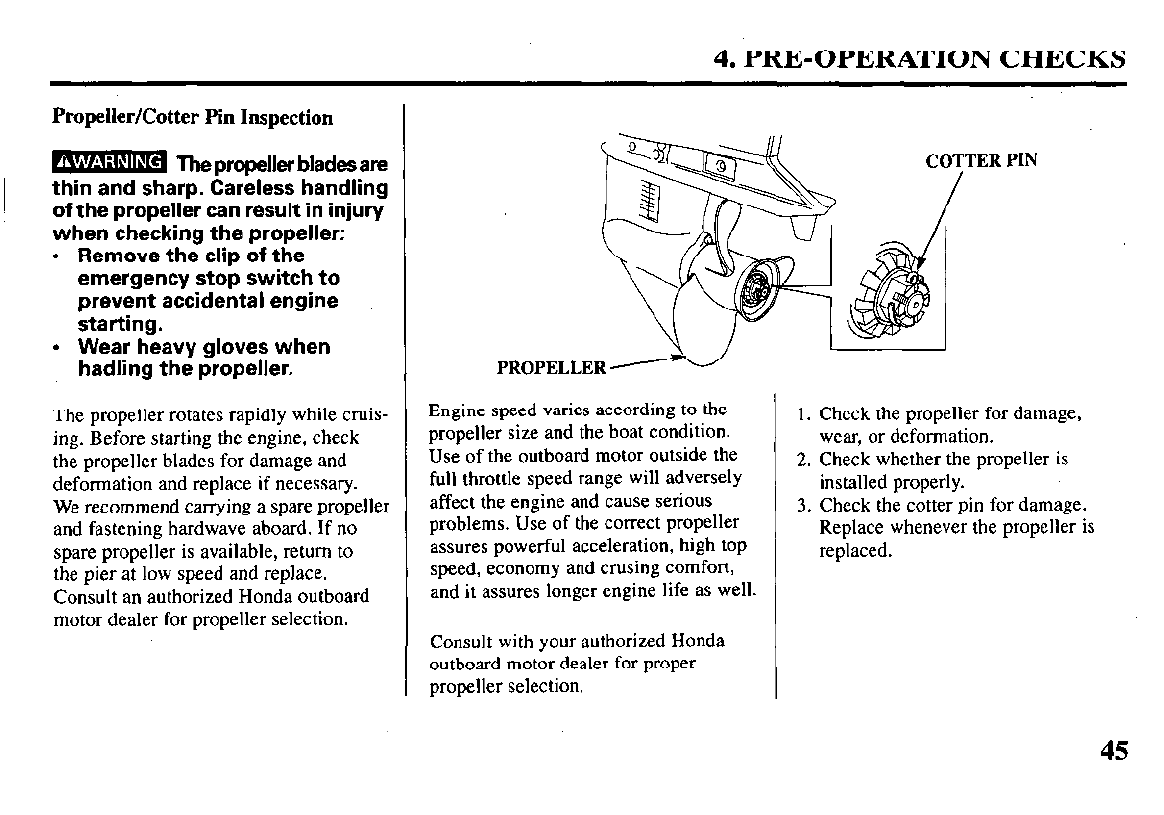
Propeller/Cotter Pin Inspection
m The propeller blades are
thin and sharp. Careless handling
of the propeller can result in injury
when checking the propeller:
. Remove the clip of the
emergency stop switch to
prevent accidental engine
starting.
l
Wear heavy gloves when
hadling the propeller.
The propeller rotates rapidly while cruis-
ing. Before starting the engine, check
the propeller blades for damage and
deformation and replace if necessary.
We recommend carrying a spare propeller
and fastening hardwave aboard. If no
spare propeller is available, return to
the pier at low speed and replace.
Consult an authorized Honda outboard
motor dealer for propeller selection.
PROPELLER d
Engine speed varies according to the
propeller size and the boat condition.
Use of the outboard motor outside the
full throttle speed range will adversely
affect the engine and cause serious
problems. Use of the correct propeller
assures powerful acceleration, high top
speed, economy and crusing comfort,
and it assures longer engine life as well.
Consult with your authorized Honda
outboard motor dealer for proper
propeller selection.
1. Check the propeller for damage,
wear, or deformation.
2. Check whether the propeller is
installed properly.
3. Check the cotter pin for damage.
Replace whenever the propeller is
replaced.
45
4. PRE-OPERATION CHECKS
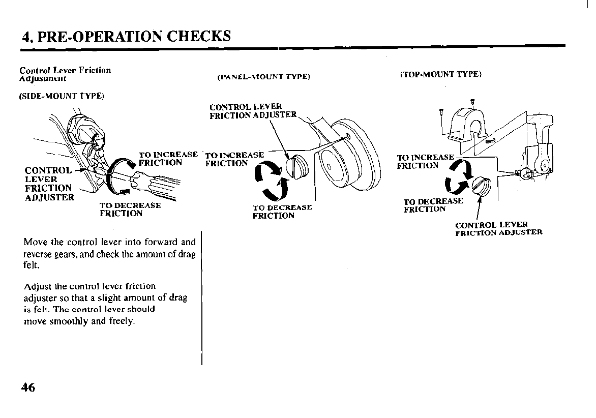
Control Lever Friction
Adjustment
(SIDE-MOUNT TYPE)
(PANEL-MOUNT TYPE)
CONTROL LEVER
TO
INCREASE
‘TO INCREA
TO DECREASE
FRICTION TO DECREASE
FRICTlON
Move the control lever into forward and
reverse gears, and check the amount of drag
felt.
Adjust the control lever friction
adjuster so that a slight amount of drag
is felt. The control lever should
move smoothly and freely.
(TOP-MOUNT TYPE)
TO INCREAS
FRICTION
TO DECREASE
FRICTION
CONTROL LEVER
FRICTION ADJUSTER
46
4. PRE-OPERATION CHECKS
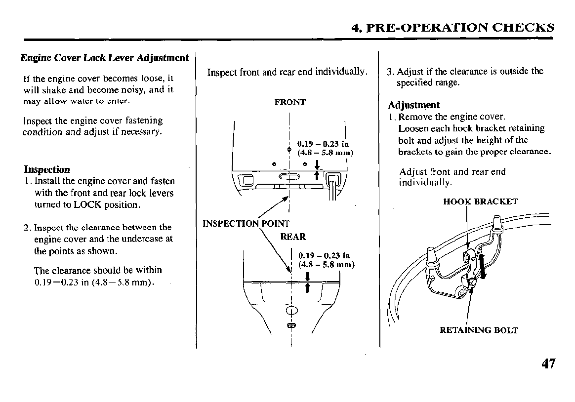
Engine Cover Lock Lever Adjustment
If the engine cover becomes loose, it
will shake and become noisy, and it
may allow water to enter.
Inspect the engine cover fastening
condition and adjust if necessary.
Inspection
1. Install the engine cover and fasten
with the front and rear lock levers
turned to LOCK position.
2. Inspect the clearance between the
engine cover and the undercase at
the points as shown.
The clearance should be within
0.19-0.23 in (4.8-5.8 mm).
Inspect front and rear end individually.
FRONT
j 019-023in I
f (4.8 - 5.i mm)
-,,
* I *
\a j
/
INSPECTION/POINT
\ REAR
0.19 - 0.23 in
3. Adjust if the clearance is outside the
specified range.
Adjustment
1. Remove the engine cover.
Loosen each hook bracket retaining
bolt and adjust the height of the
brackets to gain the proper clearance.
Adjust front and rear end
individually.
HOOK BRACKET
\ RETAINING BOLT
47
4. PRE-OPERATION CHECKS
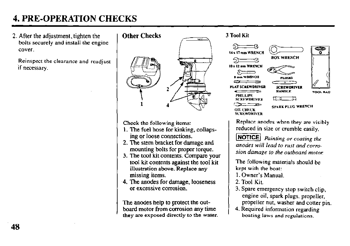
2. After the adjustment, tighten the
bolts securely and install the engine
cover.
Reinspect the clearance and readjust
if necessary.
Other Checks
1
Check the following items:
1. The fuel hose for kinking, collaps-
ing or loose connections.
2. The stem bracket for damage and
mounting bolts for proper torque.
3. The tool kit contents. Compare your
tool kit contents against the tool kit
illustration above. Replace any
missing items.
4.
The anodes for damage, looseness
or excessive corrosion.
The anodes help to protect the out-
board motor from corrosion any time
they are exposed directly to the water.
3 Tool Kit
3 G
I4 x 17 mm WRENCH
3 rg
10 I 12 mm WRKNCH
S mm WRENCH
FLAT SCREWDRIVER
cc==
BOX WRENCH
PURRS
< 0,
SCREWDRIVBR
m 0 HANDLE TOOL BAG
PHILLIPS
SCREWDRIVER -
r-
SPARK PLUG WRENCH
011. CHECK
SCREWDRIVER
Replace anodes when they are visibly
reduced in size or crumble easily.
I- Painting or coating the
anodes will lead to rust and corro-
sion damage to the outboard motor:
The following materials should be
kept with the boat:
1. Owner’s Manual.
2. Tool Kit.
3. Spare emergency stop switch clip,
engine oil, spark plugs, propeller,
propeller nut, washer and cotter pin.
4. Required information regarding
boating laws and regulations.
48

5. STARTING THE ENGINE
Optional Fuel Tank
VENT KNOB
The fuel tank must be properly se-
cured in the boat. This will protect
the fuel tank from mechanical dam-
age caused by the fuel tank shifting.
The fuel tank must be in a well venti-
lated area to reduce the chance of a
gasoline vapor explosion. Avoid di-
rect sunlight on the fuel tank.
To ensure that the outboard motor will be
able to draw fuel from the tank, do not
place the fuel tank more than 6 feet away
from the motor or lower than 3 feet below
the outboard end fuel
hose connector.
1. Open the fuel tank vent by tum-
ing the vent knob at least 2 or 3
turns counterclockwise. Allow
the air pressure inside the fuel
tank to equalize with the outside
air. With the vent open, air can en-
ter the fuel tank to displace the
fuel as the fuel level goes down.
2. Remove the fuel cap and inspect
the condition of the fuel cap and
gasket. Replace the fuel cap or
gasket if they are cracked, dam-
aged or leaking fuel.
3. Check the fuel level.
Fuel Line Connection
FUEL HOSE CONNECTOR
(FUEL TANK END)\
Inspect the fuel hose, and the O-ring
seals in the fuel hose connectors. Re-
place the fuel hose, or fuel hose con-
nectors if they are cracked, damaged
or leaking fuel. Be
sure the fuel hose
is not kinked.
1. Connect the fuel hose connector
to the fuel tank. Be sure the fuel
hose connector is securely
snapped in place.
49
5. STARTING THE ENGINE
FUEL HOSE CONNECTOR
I I I
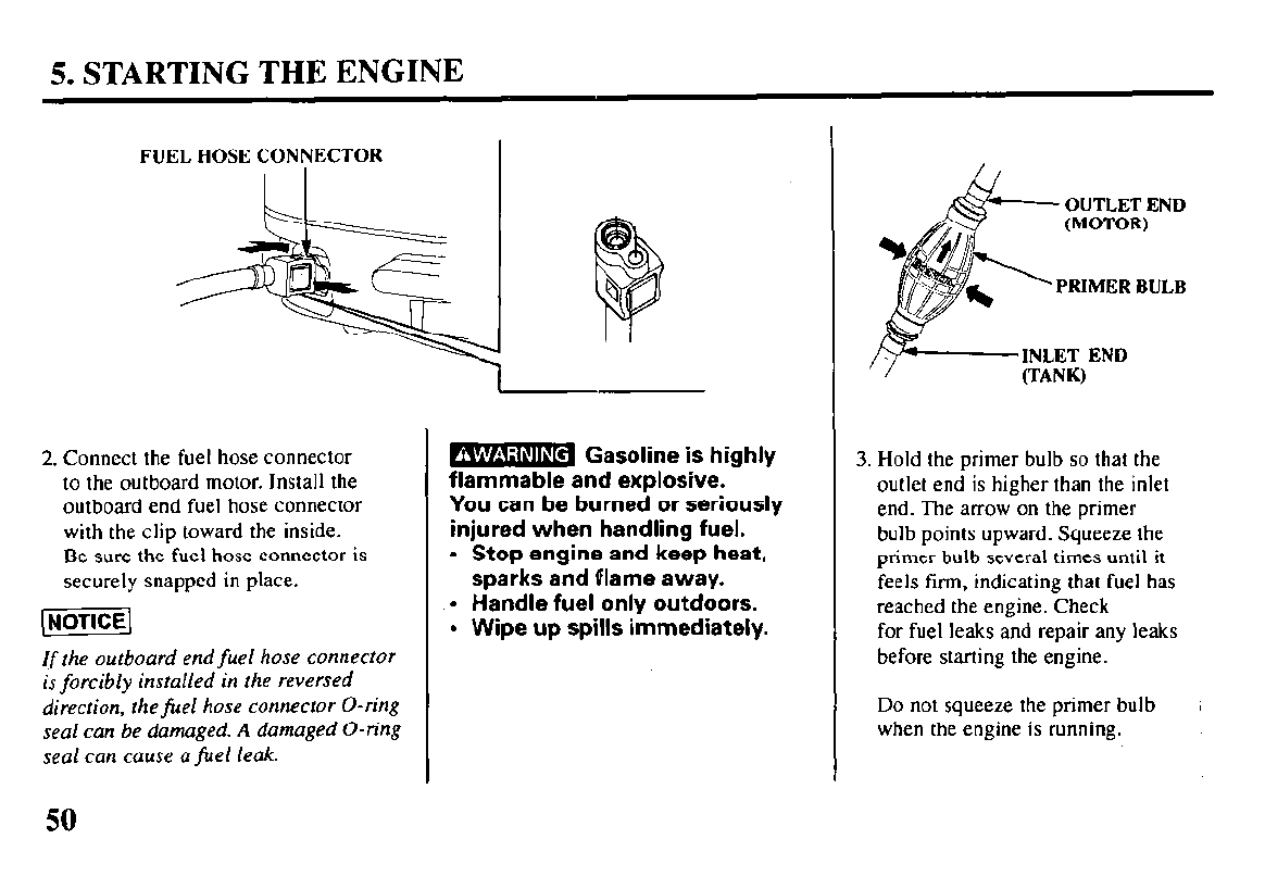
2. Connect the fuel hose connector
to the outboard motor. Install the
outboard end fuel hose connector
with the clip toward the inside.
Be sure the fuel hose connector is
securely snapped in place.
(NOTICE1
If
the outboard end
fuel
hose connector
is forcibly installed in the reversed
direction, thefuel hose connector O-ring
seal can be damaged. A damaged O-ring
seal can cause a fuel leak.
50
m Gasoline is highly
L -
flammable and explosive.
You can be burned or seriously
injured when handling fuel.
l
Stop engine and keep heat,
sparks and flame away.
l
Handle fuel only outdoors.
l
Wipe up spills immediately.
A&-
: OUTLET END
/I (MOTOR)
PRIMER BULB
3. Hold the primer bulb so that the
outlet end is higher than the inlet
end. The arrow on the primer
bulb points upward. Squeeze the
primer bulb several times until it
feels firm, indicating that fuel has
reached the engine. Check
for fuel leaks and repair any leaks
before starting the engine.
Do not squeeze the primer bulb
when the engine is running.
5. STARTING THE ENGINE (SIDE-MOUNT TYPE)
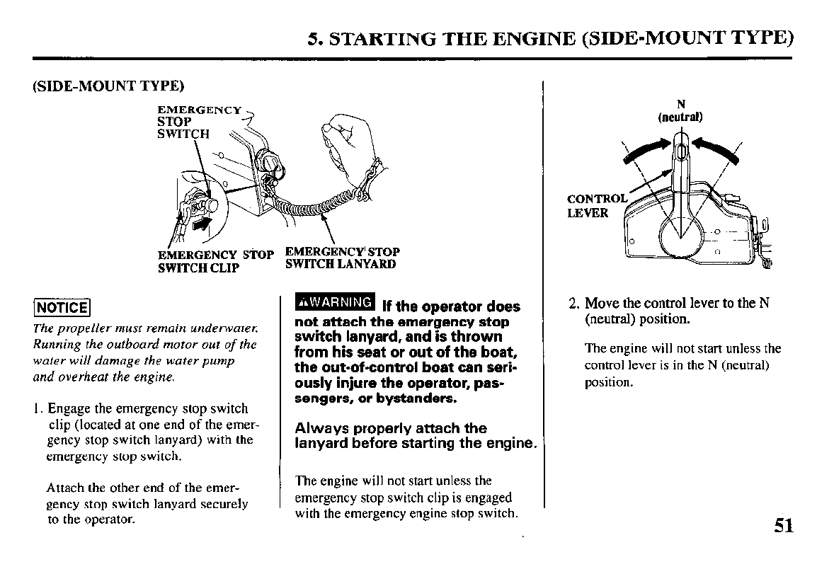
(SIDE-MOUNT TYPE)
EMERGENCY
]NOTICE]
The propeller must remain underwater.
Running the outboard motor out
of
the
water will damage the water
pump
and overheat the engine.
1. Engage the emergency stop switch
clip (located at one end of the emer-
gency stop switch lanyard) with the
emergency stop switch.
Attach the other end of the emer-
gency stop switch lanyard securely
to the operator.
B If the oPerator does
not attach the emeigency stop
switch lanyard, and is thrown
from his seat or out of the boat,
the out-of-control boat can seri-
ously injure the operator, pas-
sengers, or bystanders.
Always properly attach the
lanyard before starting the engine.
The engine will not start unless the
emergency stop switch clip is engaged
with the emergency engine stop switch.
CONTRO
LEVER
2. Move the control lever to the N
(neutral) position.
The engine will not start unless the
control lever is in the N (neutral)
position.
il
5. STARTING THE ENGINE (SIDE-MOUNT TYPE)
n
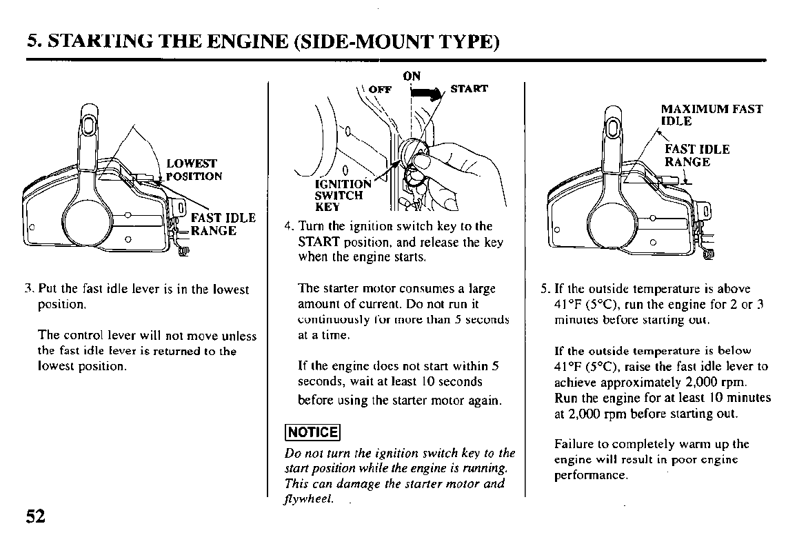
3. Put the fast idle lever is in the lowest
position.
The control lever will not move unless
the fast idle lever is returned to the
lowest position.
ON
4. Turn the ignition switch key to the
START position, and release the key
when the engine starts.
The starter motor consumes a large
amount of current. Do not run it
continuously for more than 5 seconds
at a time.
If the engine does not start within 5
seconds, wait at least 10 seconds
before using the starter motor again.
[NOTICE]
Do not turn the ignition switch key to the
start position while the engine is running.
This can damage the starter motor and
jlywheel.
MAXIMUM FAST
5. If the outside temperature is above
4 I “F (SC), run the engine for 2 or 3
minutes before starting out.
If the outside temperature is below
4 1 OF (5°C). raise the fast idle lever to
achieve approximately 2,000 rpm.
Run the engine for at least IO minutes
at 2,000 rpm before starting out.
Failure to completely warm up the
engine will result in poor engine
performance.
52
5. STARTING THE ENGINE (SIDE-MOUNT TYPE)
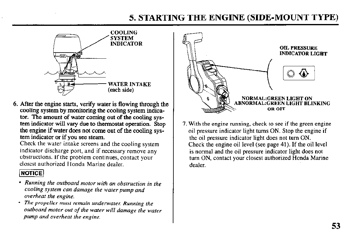
6. After the engine starts, verify water is flowing through the
cooling system by monitoring the cooling system indica-
tor. The amount of water coming out of the cooling sys-
tem indicator will vary due to thermostat operation. Stop
the engine if water does not come out of the cooling sys-
tem indicator or if you see steam.
Check the water intake screens and the cooling system
indicator discharge port, and if necessary remove any
obstructions. If the problem continues, contact your
closest authorized Honda Marine dealer.
l
Running the outboard motor with an obstruction in the
cooling system can damage the water pump and
overheat the engine.
l
The propeller must remain underwate,: Running the
outboard motor out
of
the water will damage the water
pump and overheat the engine.
OIL PRESSURE
INDICATOR LIGHT
ABNORMAL: LIGHT BLINKING
OR OFF
7. With the engine running, check to see if the green engine
oil pressure indicator light turns ON. Stop the engine if
the oil pressure indicator light does not turn ON.
Check the engine oil level (see page 41). If the oil level
is normal and the oil pressure indicator light does not
turn ON, contact your closest authorized Honda Marine
dealer.
53
5. STARTING THE ENGINE (PANEL-MOUNT TYPE)
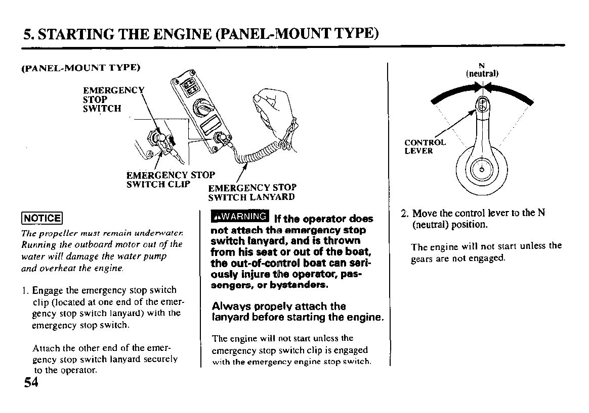
(PANEL-MOUNT TYPE)
EMERCENCY STOP
SWITCH CLIP EMER’GENCY
STOP
SWITCH LANYARD
The propeller must remain underwater
Running the outboard motor out
of
the
water will damage the water pump
and overheat the engine.
I. Engage the emergency stop switch
clip (located at one end of the emer-
gency stop switch lanyard) with the
emergency stop switch.
Attach the other end of the emer-
gency stop switch lanyard securely
to the operator.
-
If the operator does
not attach the emergency stop
switch lanyard, and is thrown
from his seat or out of the boat,
the out-of-control boat can seri-
ously injure the operator, pas-
sengers, or bystanders.
Always propely attach the
lanyard before starting the engine.
The engine will not start unless the
emergency stop switch clip is engaged
with the emergency engine stop switch.
2.
Move the control lever to the N
(neutral) position.
The engine will not start unless the
gears are not engaged.
54 -
5. STARTING THE ENGINE (PANEL-MOUNT TYPE)
OFF
START
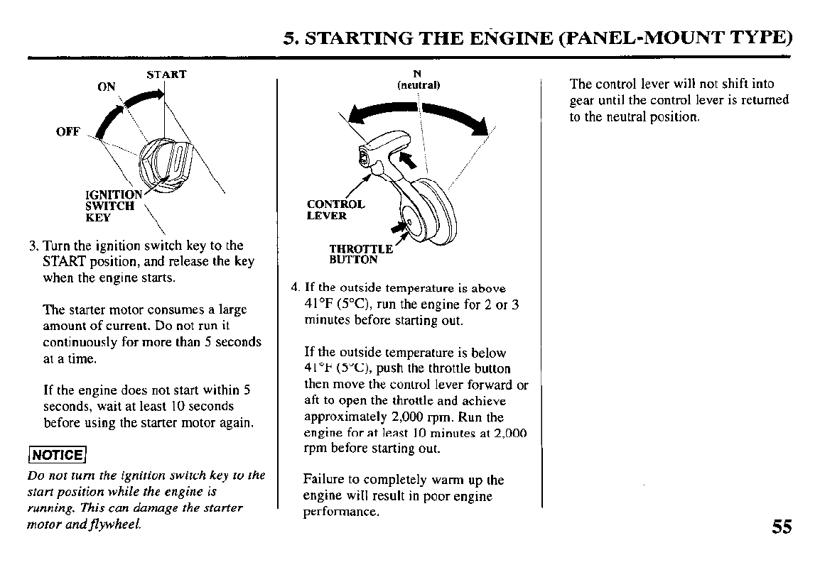
3. Turn the ignition switch key to the
START position, and release the key
when the engine starts.
The starter motor consumes a large
amount of current. Do not run it
continuously for more than 5 seconds
at a time.
If the engine does not start within 5
seconds, wait at least 10 seconds
before using the starter motor again.
Do not turn the ignition switch key to the
start position while the engine is
running. This can damage the starter
motor and flywheel.
N
(neutral)
BUTTON
4. If the outside temperature is above
41°F (YC), run the engine for 2 or 3
minutes before starting out.
If the outside temperature is below
41°F (5°C) push the throttle button
then move the control lever forward or
aft to open the throttle and achieve
approximately 2,000 ‘pm. Run the
engine for at least 10 minutes at 2,000
t-pm before starting out.
Failure to completely warm up the
engine will result in poor engine
performance.
The control lever will not shift into
gear until the control lever is returned
to the neutral position.
55
5. STARTING THE ENGINE (PANEL-MOUNT TYPE)
- 7
COOLING
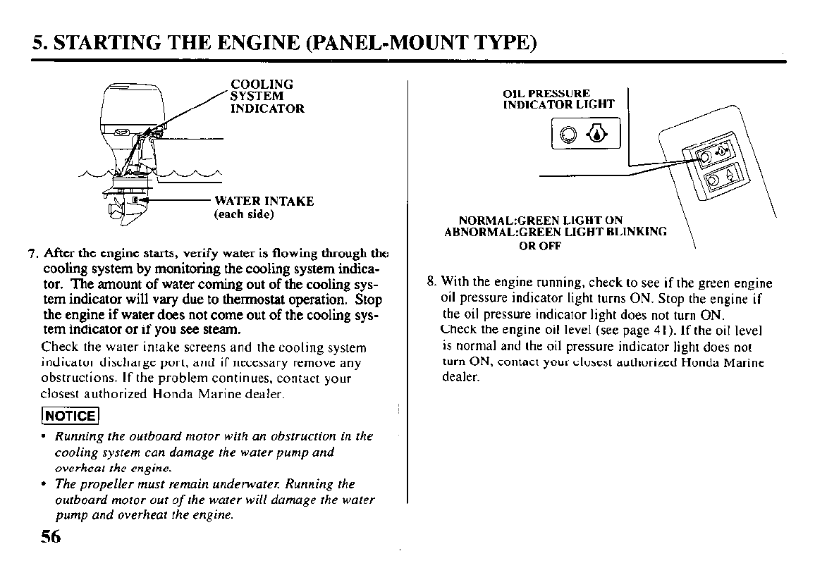
7. After the engine starts, verify water is flowing through the
cooling system by monitoring the cooling system indica-
tor. The amount of water coming out of the cooling sys-
tem indicator will vary due to thermostat operation. Stop
tire engine if water does not come out of the cooling sys-
tem indicator or if you see steam.
Check the water intake screens and the cooling system
indicator discharge port, and if necessary remove any
obstructions. If the problem continues, contact your
closest authorized Honda Marine dealer.
piEEq
l
Running the outboard motor with an obstruction in the
cooling system can damage the water pump and
overheat the engine.
l
The propeller must remain underwater: Running the
outboard motor out of the water will damage the water
pump and overheat the engine.
56
OIL PRESSURE
INDICATOR LIGHT
NORMAL:GREEN LIGHT ON
ABNORMAL:GREEN LIGHT BLINKING
OR OFF
8. With the engine running, check to see if the green engine
oil pressure indicator light turns ON. Stop the engine if
the oil pressure indicator light does not turn ON.
Check the engine oil level (see page 41). If the oil level
is normal and the oil pressure indicator light does not
turn ON, contact your closest authorized Honda Marine
dealer.
5. STARTING THE ENGINE (TOP-MOUNT TYPE)
(TOP-MOUNT TYPE)
EMERGENCY
EMERGENCY STOP EMERGENCY STOP
SWITCH LANYARD SWITCH CLIP
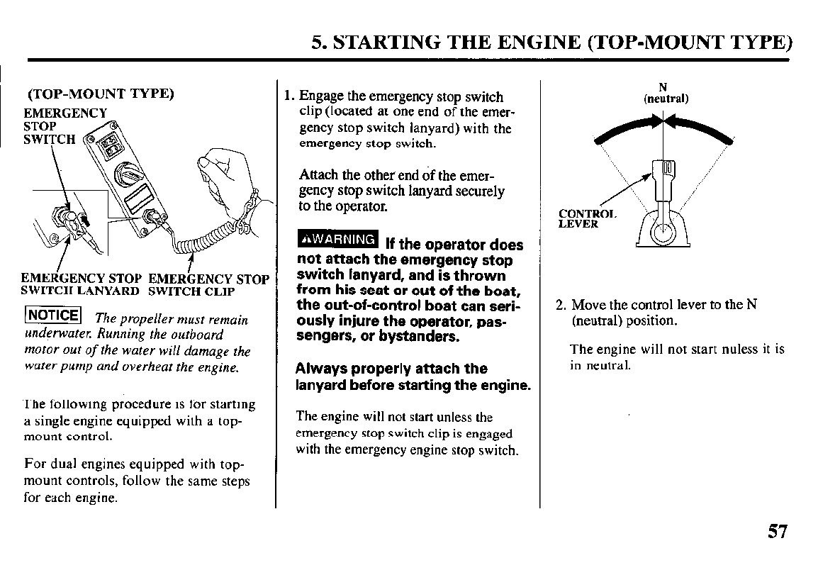
-1 Th
e propeller must remain
underwater: Running the outboard
motor out of the water will damage the
water pump and overheat the engine.
The following procedure is for starting
a single engine equipped with a top-
mount control.
For dual engines equipped with top-
mount controls, follow the same steps
for each engine.
1. Engage the emergency stop switch
clip (located at one end of the emer-
gency stop switch lanyard) with the
emergency stop switch.
Attach the other end of the emer-
gency stop switch lanyard securely
to the operator.
-
If the oDerator does
not attach the emeigency stop
switch lanyard, and is thrown
from his seat or out of the boat,
the out-of-control boat can seri-
ously injure the operator, pas-
sengers, or bystanders.
Always properly attach the
lanyard before starting the engine.
The engine will not start unless the
emergency stop switch clip is engaged
with the emergency engine stop switch.
(neutral)
.YF+ . ..”
2. Move the control lever to the N
(neutral) position.
The engine will not start nuless it is
in neutral.
57
5. STARTING THE ENGINE (TOP-MOUNT TYPE)
START
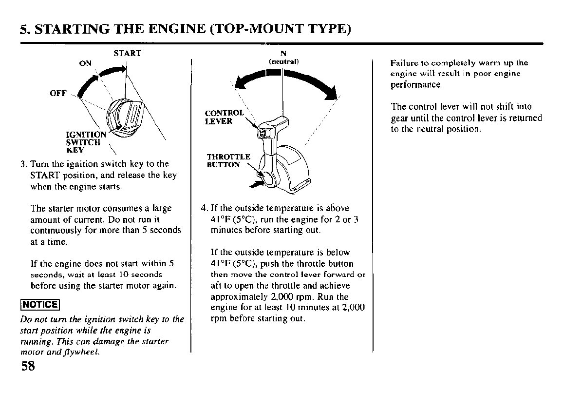
3. Turn the ignition switch key to the
START position, and release the key
when the engine starts.
The starter motor consumes a large
amount of current. Do not run it
continuously for more than 5 seconds
at a time.
If the engine does not start within 5
seconds, wait at least IO seconds
before using the starter motor again.
Do not turn the ignition switch key to rhe
start position while the engine is
running. This can damage the starter
motor andflywheel.
N
(neutral)
4. If the outside temperature is above
41 “F (5°C). run the engine for 2 or 3
minutes before starting out.
If the outside temperature is below
4 1 “F (YC), push the throttle button
then move the control lever forward or
aft to open the throttle and achieve
approximately 2,000 t-pm. Run the
engine for at least 10 minutes at 2,000
‘pm before starting out.
Failure to completely warm up the
engine will result in poor engine
performance.
The control lever will not shift into
gear until the control lever is returned
to the neutral position.
58
5. STARTING THE ENGINE (TOP-MOUNT TYPE)
-I
COOLING
SYSTEM
INDICATOR
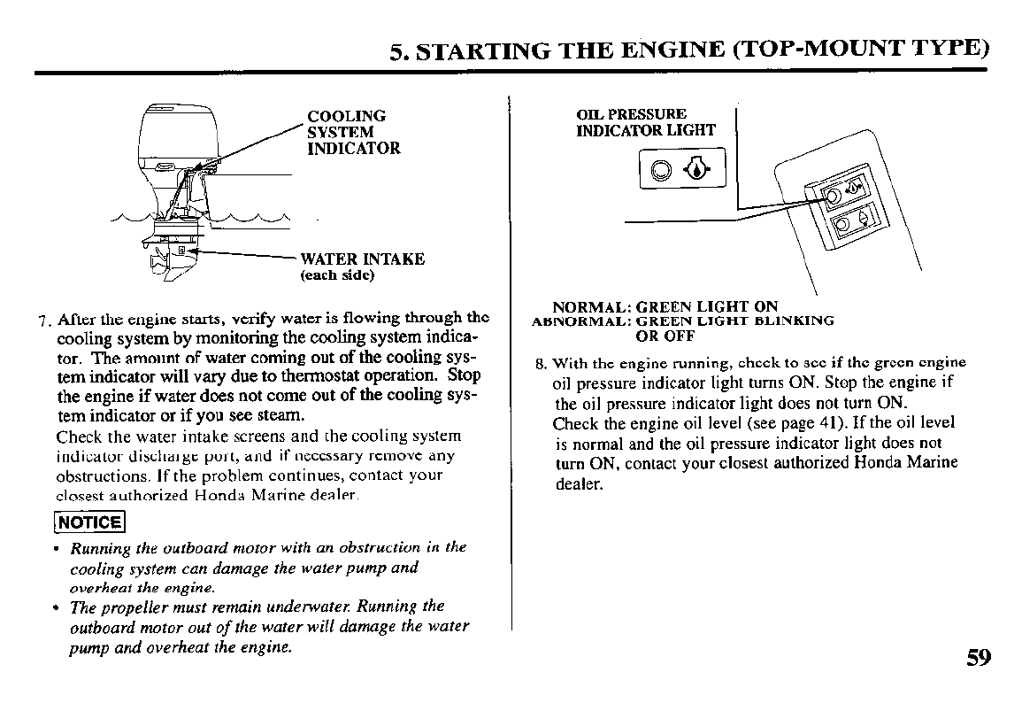
7. After the engine starts, verify water is flowing through the
cooling system by monitoring the cooling system iudica-
tor. The amount of water coming out of the cooling sys-
tem indicator will vary due to thermostat operation. Stop
the engine if water does not come out of the cooling sys-
tem indicator or if you see steam.
Check the water intake screens and the cooling system
indicator discharge port, and if necessary remove any
obstructions. If the problem continues, contact your
closest authorized Honda Marine dealer.
[NOTICE]
l
Running the outboard motor with an obstruction in the
cooling system can damage the water pump and
overheat the engine.
l
The propeller must remain underwater. Running the
outboard motor out
of
the water will damage the water
pump and overheat the engine.
OIL PRESSURE
INDICATOR LIGHT
\
NORMAL: GREEN LIGHT ON
ABNORMAL: GREEN LIGHT BLINKING
OR OFF
8. With
the engine running, check to see if the green engine
oil pressure indicator light turns ON. Stop the engine if
the oil pressure indicator light does not turn ON.
Check the
engine oil level (see page 41). If the oil level
is
normal and the oil pressure indicator light does not
turn ON, contact your closest authorized Honda Marine
dealer.
59
5. STARTING THE ENGINE (TROUBLESHOOTING)
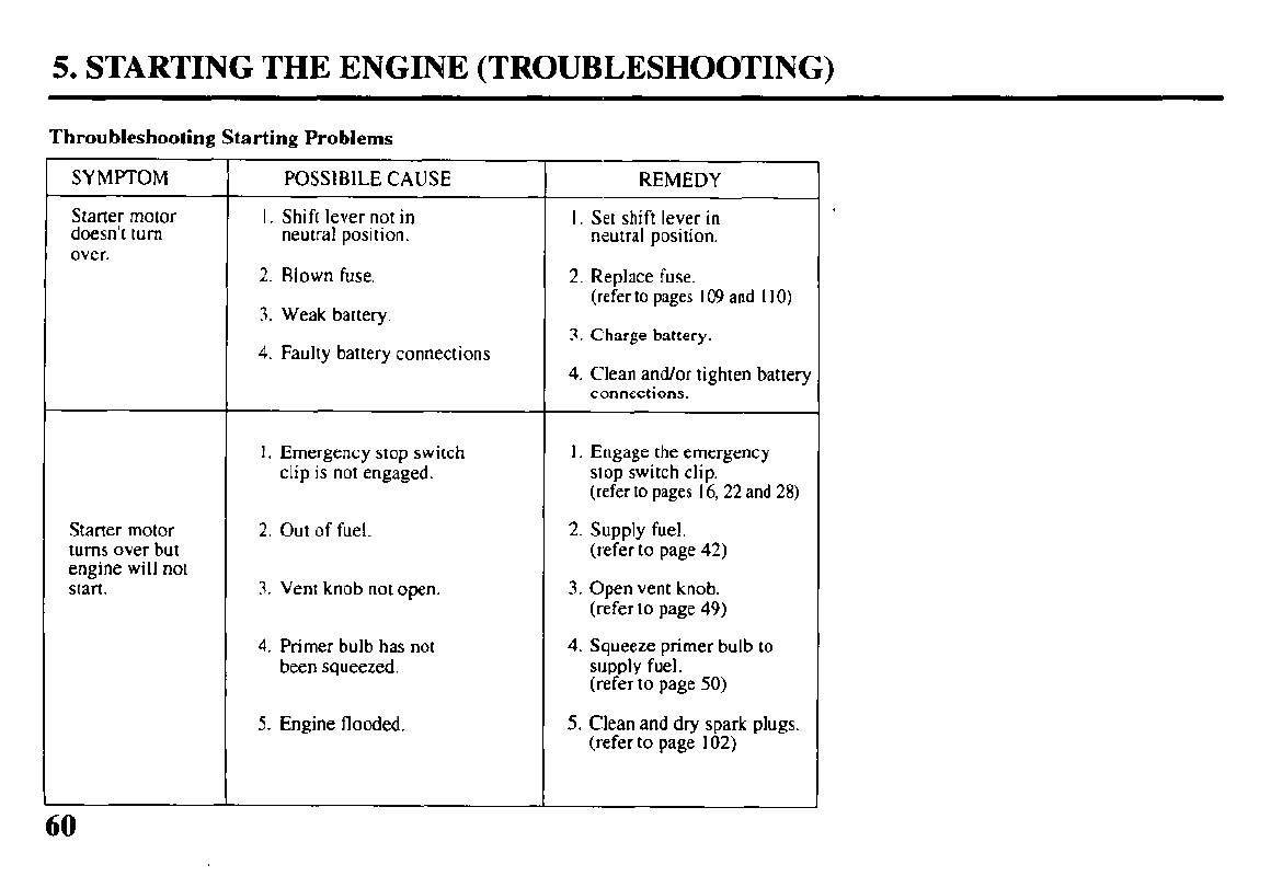
Throubleshooting Starting Problems
SYMPTOM
Starter motor
doesn’t turn
over.
POSSIBILE CAUSE
1. Shift lever not in
neutral position.
2. Blown fuse.
3. Weak battery.
REMEDY
1. Set shift lever in
neutral position.
2. Replace fuse.
(refer to pages I09 and I IO)
3. Charge battery.
4. Faulty battery connections 4. Clean and/or tighten battery
connections.
I. Emergency stop switch
clip is not engaged. I. Engage the emergency
stop switch clip.
(refer to pages I6,22 and 28)
Starter motor
turns over but
engine will not
start.
2. Out of fuel.
3. Vent knob not open.
2. Supply fuel.
(refer to page 42)
3. Open vent knob.
(refer to page 49)
4. Primer bulb has not
been squeezed. 4. Squeeze primer bulb to
supply fuel.
(refer to page 50)
5. Engine flooded. 5. Clean and dry spark plugs.
(refer to page 102)
6. OPERATION
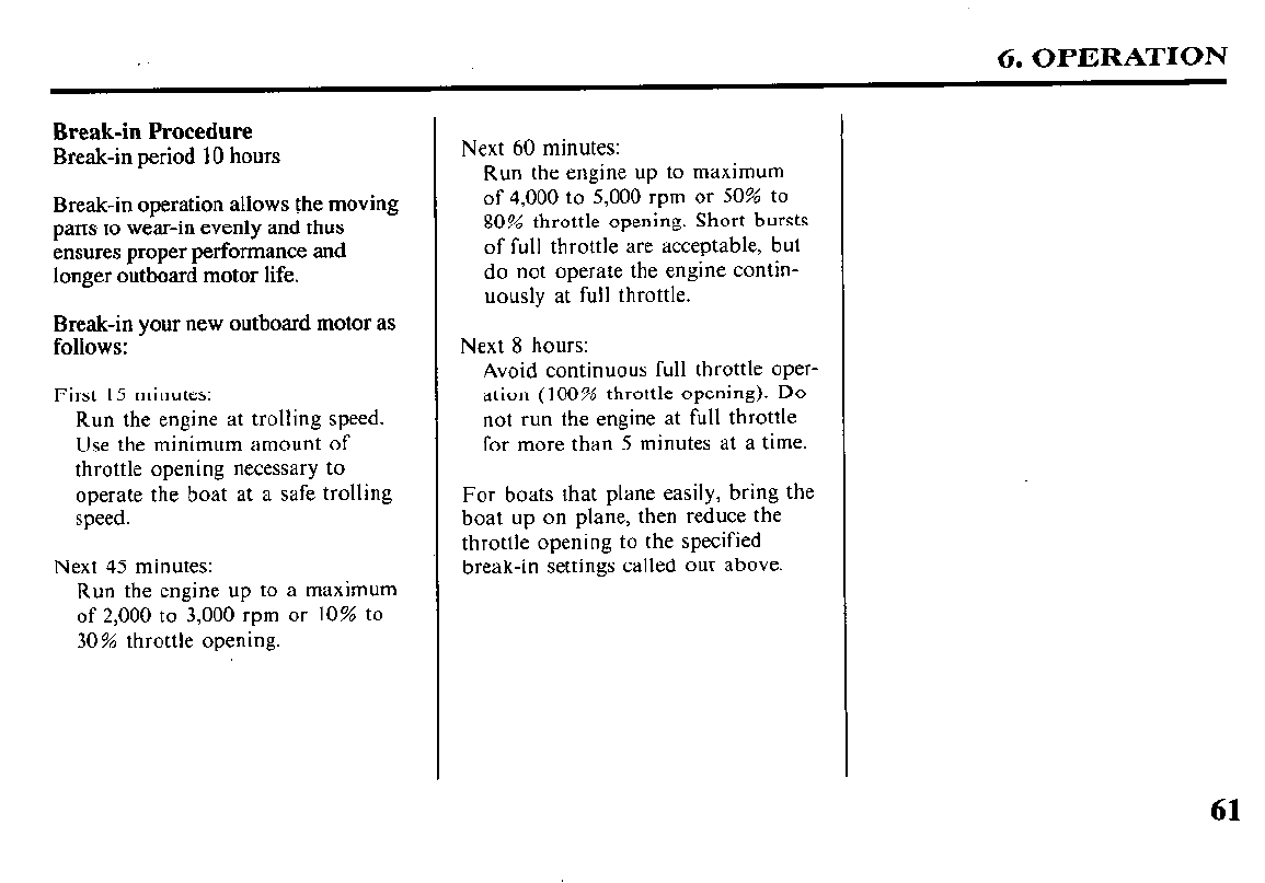
Break-in Procedure
Break-in period 10 hours
Break-in operation allows the moving
parts to wear-in evenly and thus
ensures proper performance and
longer outboard motor life.
Break-in your new outboard motor as
follows:
First 15 minutes:
Run the engine at trolling speed.
Use the minimum amount of
throttle opening necessary to
operate the boat at a safe trolling
speed.
Next 45 minutes:
Run the engine up to a maximum
of 2,000 to 3,000 rpm or 10% to
30% throttle opening.
Next 60 minutes:
Run the engine up to maximum
of 4,000 to 5,000 rpm or 50% to
80% throttle opening. Short bursts
of full throttle are acceptable, but
do not operate the engine contin-
uously at full throttle.
Next 8 hours:
Avoid continuous full throttle oper-
ation (100% throttle opening). Do
not run the engine at full throttle
for more than 5 minutes at a time.
For boats that plane easily, bring the
boat up on plane, then reduce the
throttle opening to the specified
break-in settings called out above.
61
6. OPERATION (SIDE-MOUNT TYPE)
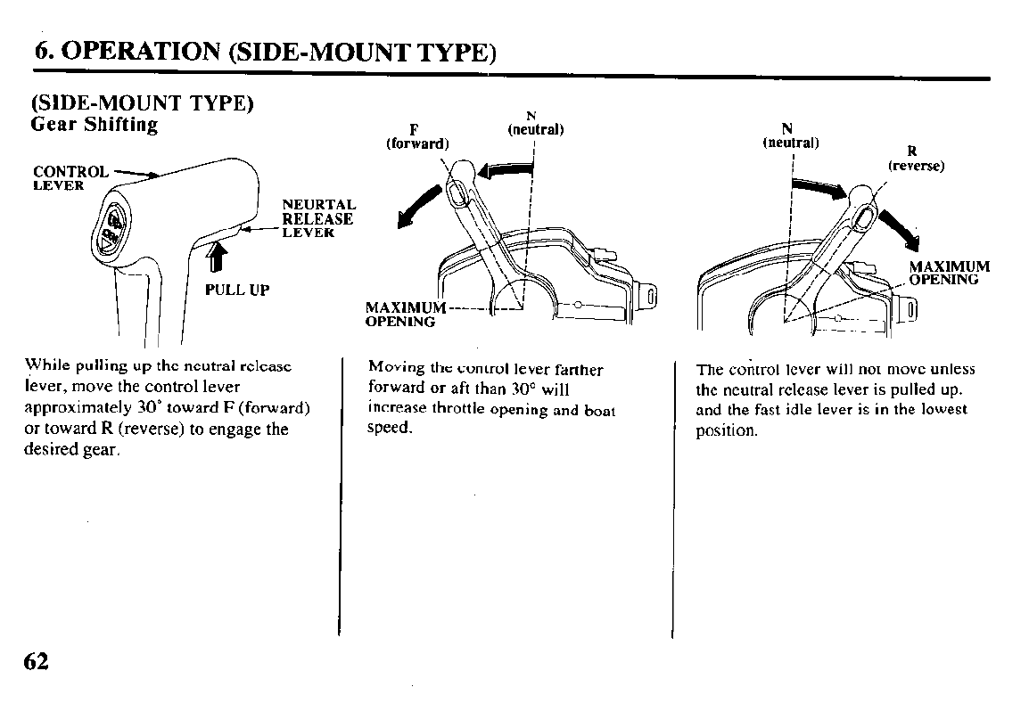
(SIDE-MOUNT TYPE)
Gear Shifting
N
(neutral)
I
While
pulling up the neutral release
lever, move the control lever
approximately 30” toward F (forward)
or toward R (reverse) to engage the
desired gear.
Moving the control lever farther The control lever will not move unless
forward or aft than 30“ will the neutral release lever is pulled up.
increase throttle opening and boat and the fast idle lever is in the lowest
speed. position.
N
(neutral)
I
I
R
(reverse)
MAXIMUM
62
6. OPERATION (SIDE-MOUNT TYPE)
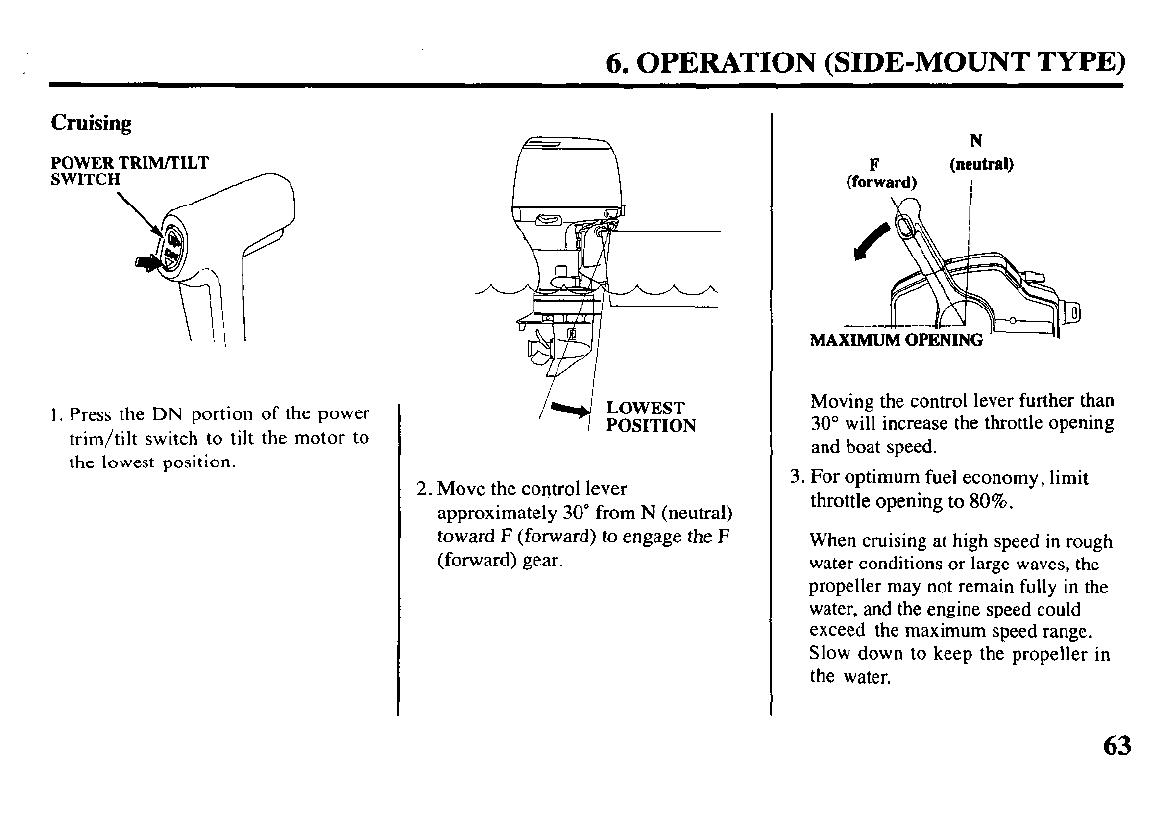
Cruising
POWER TRIM/TILT
SWITCH
I. Press the DN portion of the power
trim/tilt switch to tilt the motor to
the lowest position.
LOWEST
POSITION
2. Move the control lever
approximately 30” from N (neutral)
toward F (forward) to engage the F
(forward) gear.
N
F
(neutral)
(forward)
\n i
Moving the control lever further than
30” will increase the throttle opening
and boat speed.
3. For optimum fuel economy, limit
throttle opening to 80%.
When cruising at high speed in rough
water conditions or large waves, the
propeller may not remain fully in the
water, and the engine speed could
exceed the maximum speed range.
Slow down to keep the propeller in
the water.
63
6. OPERATION (PANEL-MOUNT TYIPE)
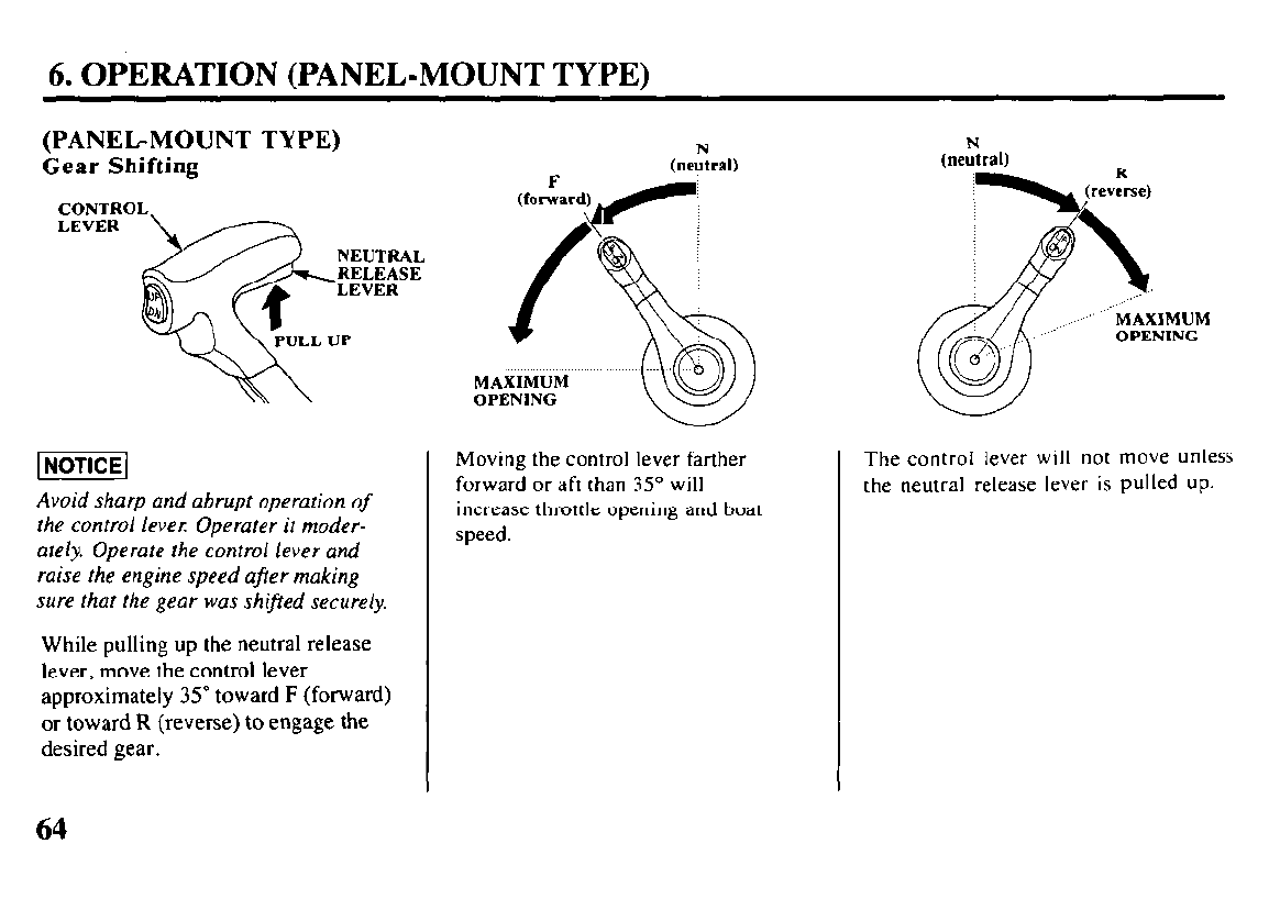
(PANEGMOUNT TYPE)
Gear Shifting
N
(neutral)
OPENING
lNOTlCEl
Avoid sharp and abrupt operation
of
the control lever: Operater it moder-
ately. Operate the control lever and
raise the engine speed ajier making
sure that the gear was shifted securely.
While pulling up the neutral release
lever, move the control lever
approximately 35’ toward F (forward)
or toward R (reverse) to engage the
desired gear.
Moving the control lever farther
forward or aft than 35” will
increase throttle opening and boat
speed.
The control lever will not move unless
the neutral release lever is pulled up.
6. OPERATION (PANEL-MOUNT TYPE)
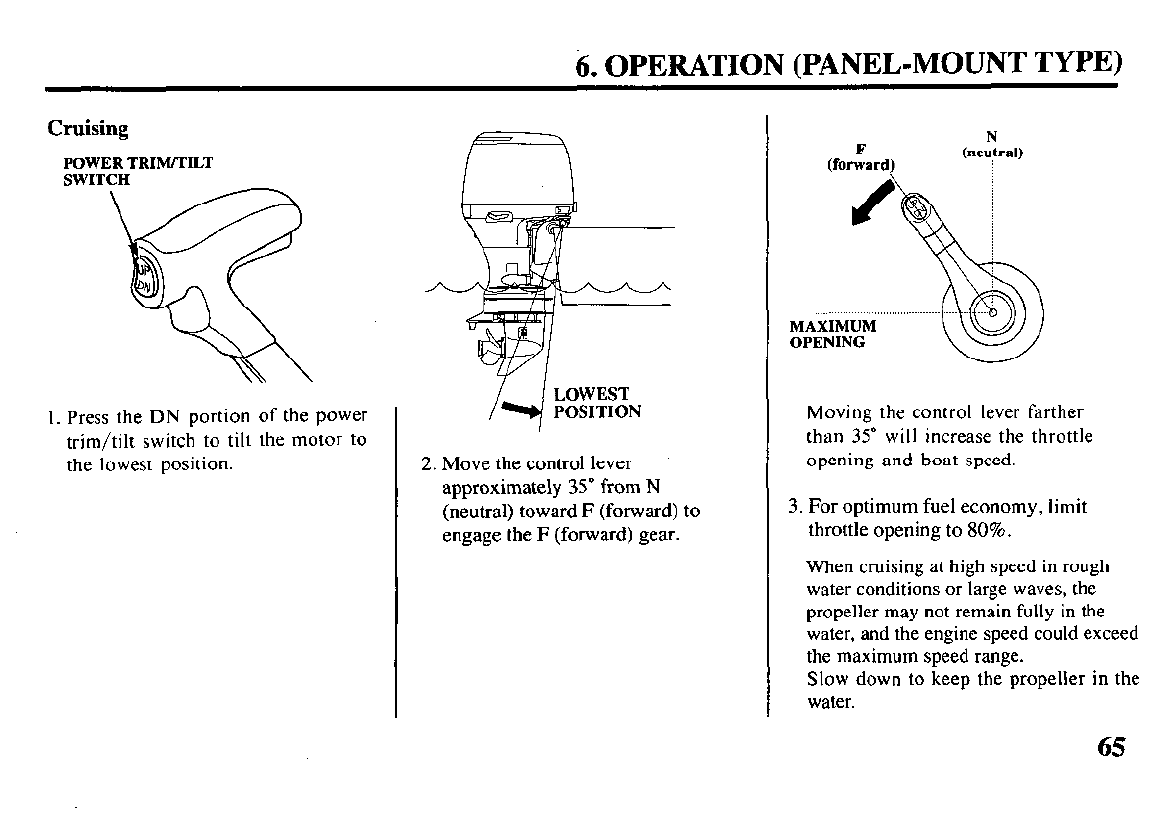
Cruising
POWER TRIM/TILT
SWITCH
I. Press the DN portion of the power
trim/tilt switch to tilt the motor to
the lowest position.
LOWEST
POSITION
2. Move the control lever
approximately 35’ from N
(neutral) toward F (forward) to
engage the F (forward) gear.
Moving the control lever farther
than 35” will increase the throttle
opening and boat speed.
3. For optimum fuel economy, limit
throttle opening to 80%.
When cruising at high speed in rough
water conditions or large waves, the
propeller may not remain fully in the
water, and the engine speed could exceed
the maximum speed range.
Slow down to keep the propeller in the
water.
65
6. OPERATION (TOP-MOUNT TYPEj
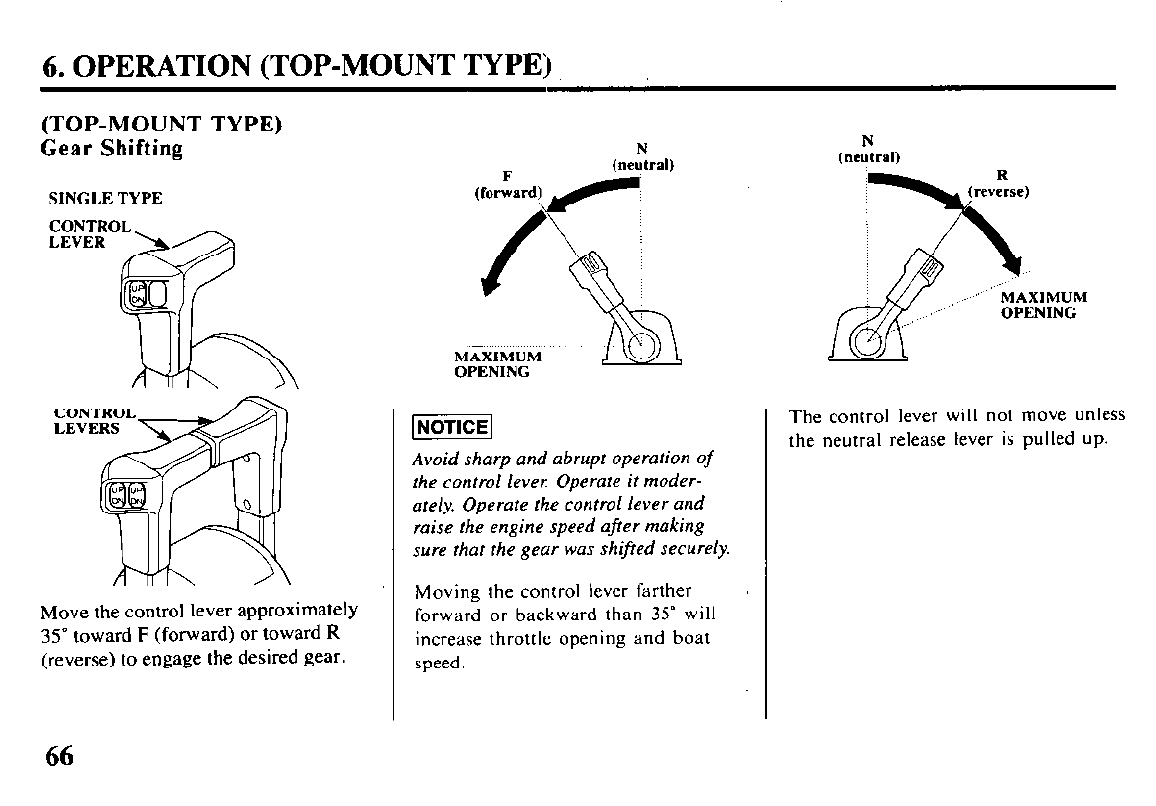
(TOP-MOUNT TYPE)
Gear Shifting
SINGLE TYPE
Move the control lever approximately
35” toward F (forward) or toward R
(reverse) to engage the desired gear.
N
MAXIMUM
OPENING
Avoid sharp and abrupt operation
of
the control lever: Operate it moder-
ately. Operate the control lever and
raise the engine speed afrer making
sure that the geur was shifed securely.
Moving the control lever farther
forward or backward than 35” will
increase throttle opening and boat
speed.
N
(neutral)
OPENING
The control lever will not move unless
the neutral release lever is pulled up.
66
6. OPERATION (TOP-MOUNT TYPE)
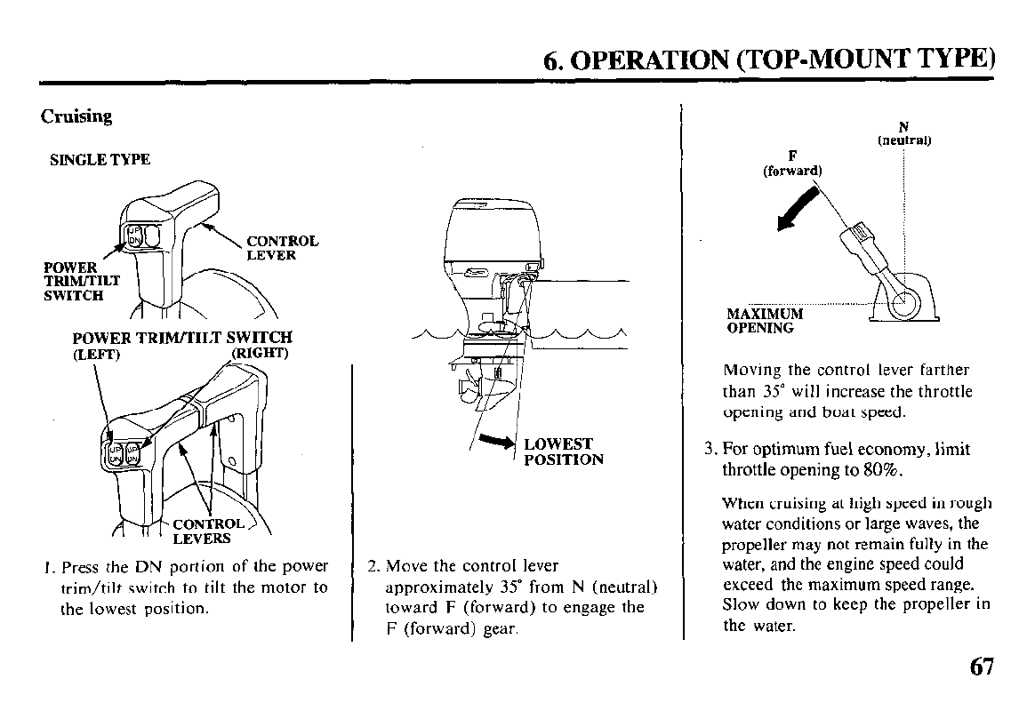
Cruising
SINGLE TYPE
POWER TRIM/TILT SWITCH
I. Press the DN portion of the power
trim/tilt switch to tilt the motor to
the lowest position.
LOWEST
POSITION
2. Move the control lever
approximately 35” from N (neutral)
toward F (forward) to engage the
F (forward) gear.
F
(forward)
N
(neutral)
0 8 /
--------.- ~
MAXIMUM
OPENING
Moving the control lever farther
than 35” will increase the throttle
opening and boat speed.
3. For optimum fuel economy, limit
throttle opening to 80%.
When cruising at high speed in rough
water conditions or large waves, the
propeller may not remain fully in the
water, and the engine speed could
exceed the maximum speed range.
Slow down to keep the propeller in
the water.
67
6. OPERATION (POWER TRIM/TILT)
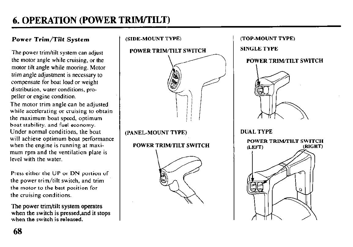
Power Trim/Tilt System
The power trim/tilt system can adjust
the motor angle while cruising, or the
motor till angle while mooring. Motor
trim angle adjustment is necessary to
compensate for boat load or weight
distribution. water conditions, pro-
peller or engine condition.
The motor trim angle can be adjusted
while accelerating or cruising to obtain
the maximum boat speed, optimum
boat stability, and fuel economy.
Under normal conditions, the boat
will achieve optimum boat performance
when the engine is running at maxi-
mum rpm and the ventilation plate is
level with the water.
Press either the UP or DN portion of
the power trim/tilt switch, and trim
the motor to the best position for
the cruising conditions.
The power trim/tilt system operates
when the switch is pressed,and it stops
when the switch is released.
68
(SIDE-MOUNT TYPE)
POWER TRIM/TILT SWITCH
(PANEL-MOUNT TYPE)
POWER TRIM/TILT SWITCH
(TOP-MOUNT TYPE)
SINGLE TYPE
POWER TRIM/TILT SWITCH
DUAL TYPE
POWER TRIM/TILT SWITCH
(RIGHT)
6. OPERATION (POWER TRIM/TILT)
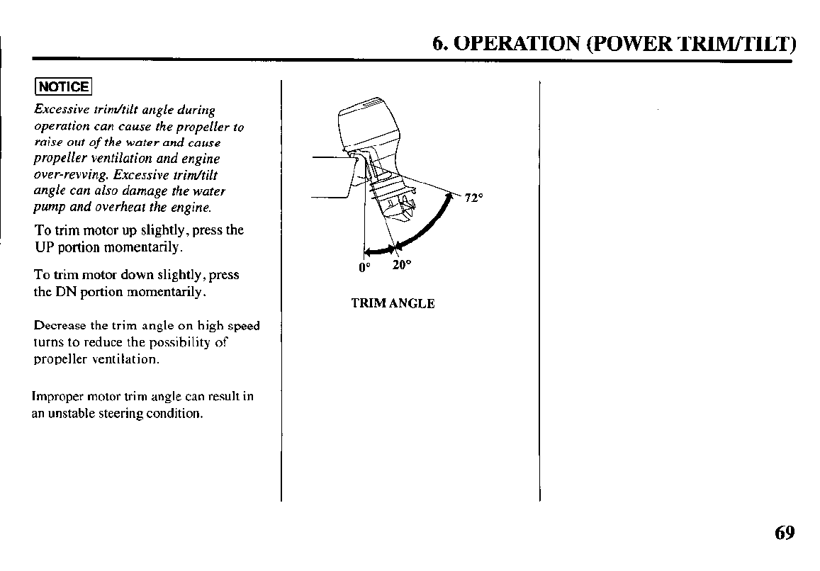
INOTICE~
Excessive trim/tilt angle during
operation can cause the propeller to
raise out of the water and cause
propeller ventilation and engine
over-revving. Excessive trim/tilt
angle can also damage the water
pump and overheat the engine.
To trim motor up slightly, press the
UP portion momentarily.
To trim motor down slightly, press
the DN portion momentarily.
Decrease the trim angle on high speed
turns to reduce the possibility of
propeller ventilation.
Improper motor trim angle can result in
an unstable steering condition.
72O
TRIM ANGLE
69
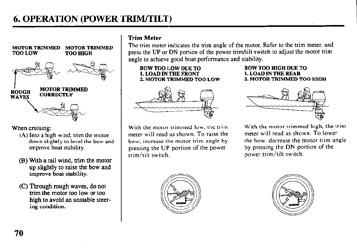
6. OPERATION (POWER TRIM/TILT)
MOTOR TRIMMED MOTOR TRIMMED
TOO LOW TOO HIGH
R’O”GH MOTOR TRIMMED
WAVES CORRECTLY
When cruising:
(A)
Into a high wind, trim the motor
down slightly to level the bow and
improve boat stability.
(B) With a tail wind, trim the motor
up slightly to raise the bow and
improve boat stability.
(C) Through rough waves, do not
trim the motor too low or too
high to avoid an unstable steer-
ing condition.
Trim Meter
The trim meter indicates the trim angle of the motor. Refer to the trim meter, and
press the UP or DN portion of the power trim/tilt switch to adjust the motor trim
angle to achieve good boat performance and stability.
BOW TOO LOW DUE TO
1. LOAD IN THE FRONT
2. MOTOR TRIMMED TOO LOW
With the motor trimmed low, the trim
meter will read as shown. To raise the
bow, increase the motor trim angle by
pressing the UP portion of the power
trim/tilt switch.
BOW TOO HIGH DUE TO
1. LOAD IN THE REAR
2. MOTOR TRIMMED TOO HIGH
With the motor trimmed high, the trim
meter will read as shown. To lower
the bow, decrease the motor trim angle
by pressing the DN portion of the
power trim/tilt switch.
70
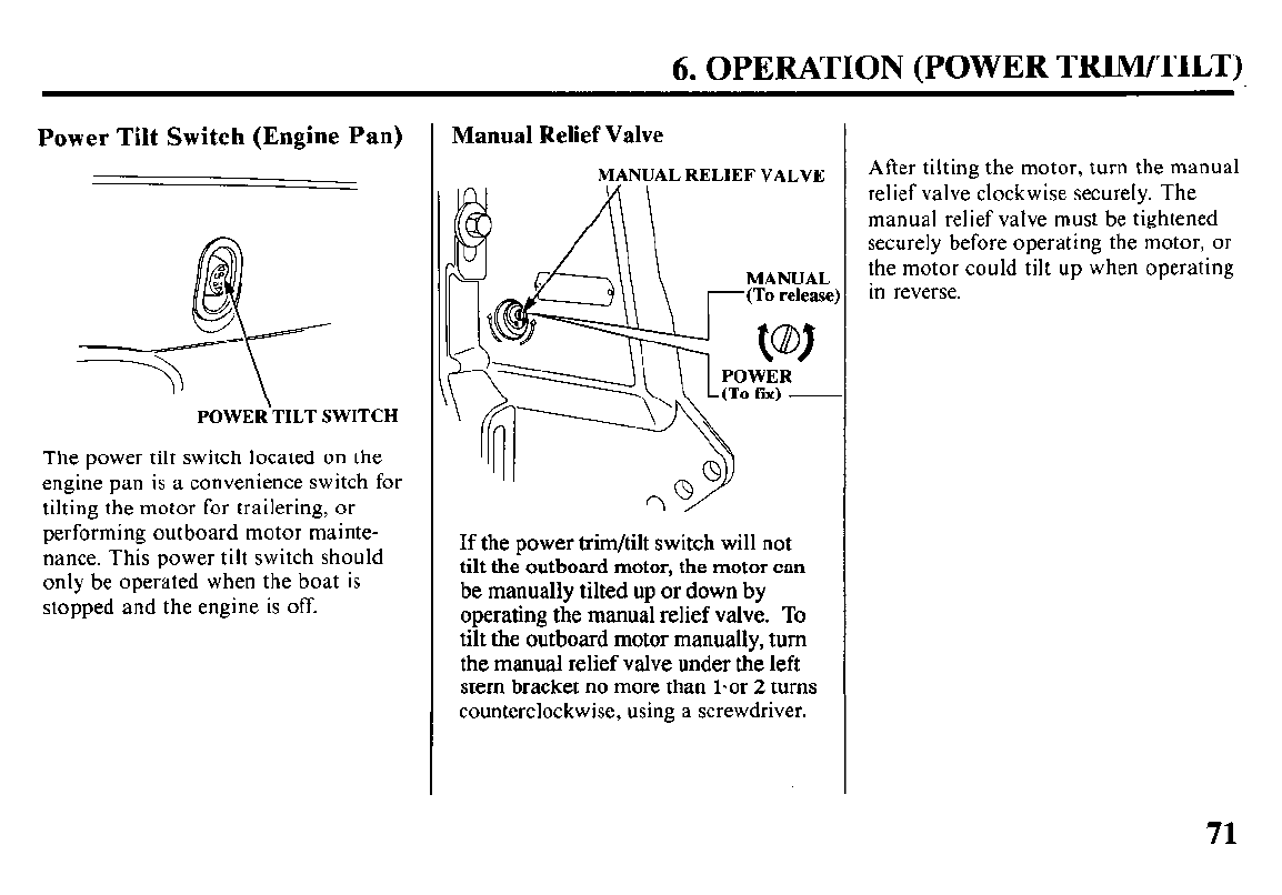
6. OPERATION (POWER TRIM/TILT)
Power Tilt Switch (Engine Pan)
POWER‘TILT SWITCH
The power tilt switch located on the
engine pan is a convenience switch for
tilting the motor for trailering, or
performing outboard motor mainte-
nance. This power tilt switch should
only be operated when the boat is
stopped and the engine is off.
Manual Relief Valve
MANUAL RELIEF VALVE
If the power trim/tilt switch will not
tilt the outboard motor, the motor can
be manually tilted up or down by
operating the manual relief valve. To
tilt the outboard motor manually, turn
the manual relief valve under the left
stem bracket no more than l-or 2 turns
counterclockwise, using a screwdriver.
After tilting the motor, turn the manual
relief valve clockwise securely. The
manual relief valve must be tightened
securely before operating the motor, or
the motor could tilt up when operating
in reverse.
71
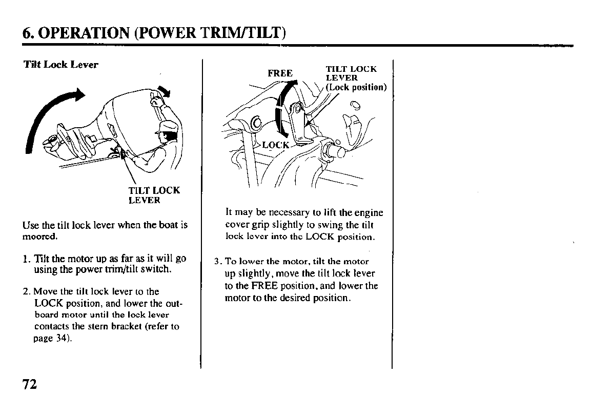
6. OPERATION (POWER TRIM/TILT)
Tilt Lock Lever
TILT LOCK
LEVER
Use the tilt lock lever when the boat is
moored.
1. lilt
the motor up as far as it will go
using the power trim/tilt switch.
2. Move the tilt lock lever to the
LOCK position, and lower the out-
board motor until the lock lever
contacts the stern bracket (refer to
page 34).
TILT LOCK
It may be necessary to lift the engine
cover grip slightly to swing the tilt
lock lever into the
LOCK
position.
3.
To
lower the motor, tilt the motor
up slightly, move the tilt lock lever
to the FREE position, and lower the
motor to the desired position.
72
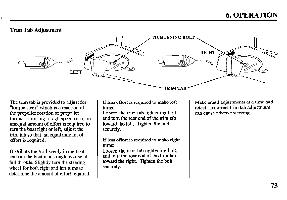
6. OPERATION
Trim Tab Adjustment
TIGHTENING BOLT
The trim tab is provided to adjust for
“torque steer” which is a reaction of
the propeller rotation or propeller
torque. If during a high speed turn, an
unequal amount of effort is required to
turn the boat right or left, adjust the
trim tab so that an equal amount of
effort is required.
Distribute the load evenly in the boat,
and run the boat in a straight course at
full throttle. Slightly turn the steering
wheel for both right and left turns to
determine the amount of effort required.
If less effort is required to make left
turns:
Loosen the trim tab tightening bolt,
and turn the rear end of the trim tab
toward the left. Tighten the bolt
securely.
If less effort is required to make right
turns:
Loosen the trim tab tightening bolt,
and turn the rear end of the trim tab
toward the right. Tighten the bolt
securely.
Make
small adjustments at a time and
retest. Incorrect trim tab adjustment
can cause adverse steering.
73
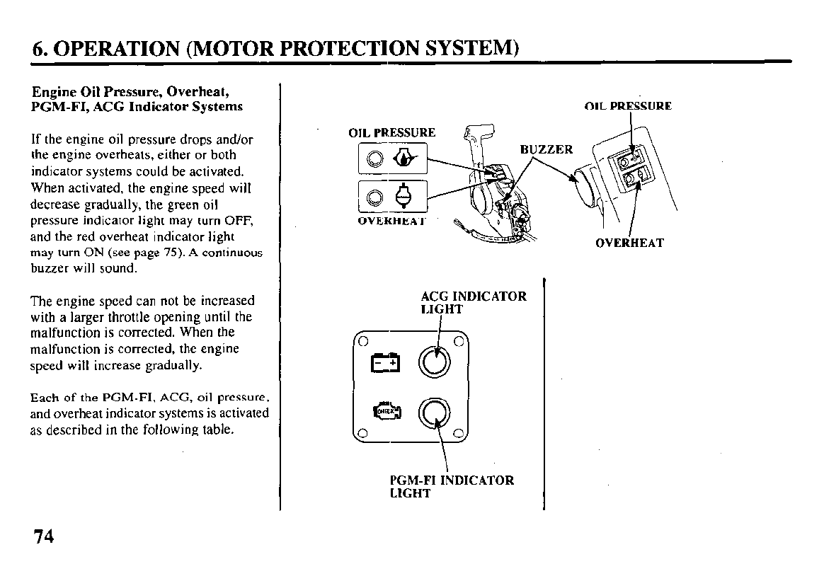
6. OPERATION (MOTOR PROTECTION SYSTEM)
Engine Oil Pressure, Overheat,
PGM-FI, ACG Indicator Systems
If the engine oil pressure drops and/or
the engine overheats, either or both
indicator systems could be activated.
When activated, the engine speed will
decrease gradually, the green oil
pressure indicator light may turn OFF,
and the red overheat indicator light
may turn ON (see page 75). A continuous
buzzer will sound.
The engine speed can not be increased
with a larger throttle opening until the
malfunction is corrected. When the
malfunction is corrected, the engine
speed will increase gradually.
Each of the PGM-FI, ACG, oil pressure,
and overheat indicator systems is activated
as described in the following table.
OIL PRESSURE
OVER’HEAT
ACG INDICATOR
LIGHT
I
Om O
u
e
0 0
PGM-FI INDICATOR
LIGHT
74
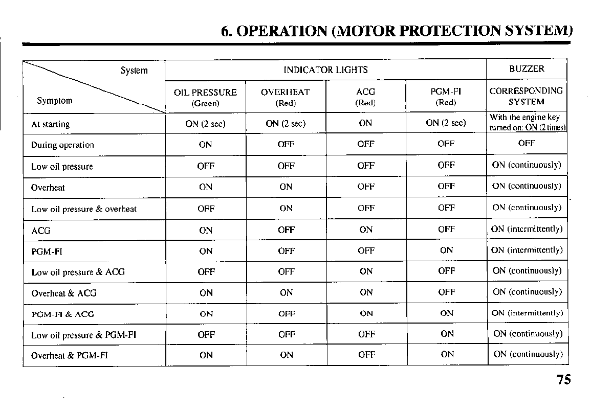
6. OPERATION (MOTOR PROTECTION SYSTEM)
PGM-FI ON
Low oil pressure & ACG OFF
Overheat & ACG ON
PGM-FI & ACG ON
Low oil pressure & PGM-FI OFF
Overheat & PGM-FI ON
OFF
OFF
ON
OFF
OFF
ON
OFF
ON
ON
ON
OFF
OFF
ON
OFF
OFF
ON
ON
ON
ON (intermittently)
ON (continuously)
ON (continuously)
ON (intermittently)
ON (continuously)
ON (continuously)
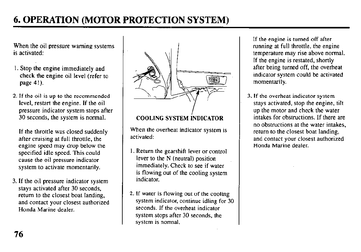
6. OPERATION (MOTOR PROTECTION SYSTEM)
When the oil pressure warning systems
is activated:
1. Stop the engine immediately and
check the engine oil level (refer to
page 41).
2. If the oil is up to the recommended
level, restart the engine. If the oil
pressure indicator system stops after
30 seconds, the system is normal.
If the throttle was closed suddenly
after cruising at full throttle, the
engine speed may drop below the
specified idle speed. This could
cause the oil pressure indicator
system to activate momentarily.
3. If the oil pressure indicator system
stays activated after 30 seconds,
return to the closest boat landing,
and contact your closest authorized
Honda Marine dealer.
COOLING SYSTEM iNDICATOR
When the overheat indicator system is
activated:
1. Return the gearshift lever or control
lever to the N (neutral) position
immediately. Check to see if water
is flowing out of the cooling system
indicator.
2. If water is flowing out of the cooling
system indicator, continue idling for 30
seconds. If the overheat indicator
system stops after 30 seconds, the
system is normal.
If the engine is turned off after
running at full throttle, the engine
temperature may rise above normal.
If the engine is restated, shortly
after being turned off, the overheat
indicator system could be activated
momentarily.
3. If the overheat indicator system
stays activated, stop the engine, tilt
up the motor and check the water
intakes for obstructions. If there are
no obstructions at the water intakes,
return to the closest boat landing,
and contact your closest authorized
Honda Marine dealer.
76
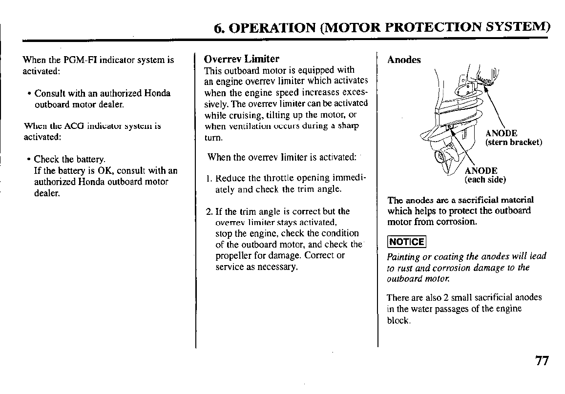
6. OPERATION (MOTOR PROTECTION SYSTEM)
When the PGM-FI indicator system is
activated:
l
Consult with an authorized Honda
outboard motor dealer.
When the ACG indicator system is
activated:
l
Check the battery.
If the battery is OK, consult with an
authorized Honda outboard motor
dealer.
Overrev Limiter
This outboard motor is equipped with
an engine overrev limiter which activates
when the engine speed increases exces-
sively. The overrev limiter can be activated
while cruising, tilting up the motor, or
when ventilation occurs during a sharp
turn.
When the overrev limiter is activated:
1. Reduce the throttle opening immedi-
ately and check the trim angle.
2. If the trim angle is correct but the
overrev limiter stays activated,
stop the engine, check the condition
of the outboard motor, and check the’
propeller for damage. Correct or
service as necessary.
Anodes
acket)
(each side)
The anodes are a s&crificial material
which helps to protect the outboard
motor from corrosion.
Painting or coating the anodes will lead
to rust and corrosion damage to the
outboard motor:
There are also 2 small sacrificial anodes
in the water passages of the engine
block.
6. OPERATION
Shallow Water Operation
Excessive trim/tilt angle during
operation can cause the propeller to
raise out of the water and cause
propeller ventilation and engine
over-revving. Excessive trim/tilt
angle can also damage the water
pump and overheat the engine.
Water pump failure due to propeller
ventilation is not covered under the
Distributor’s Limited Warranty.
When operating in shallow water, tilt
the motor up to prevent the propeller
and gear case from hitting the bottom
With the motor tilted up, operate the
engine at low speed.
Monitor the cooling system indicator
for water discharge. Be sure that the
motor is not tilted so high that the
water intakes are out of the water.
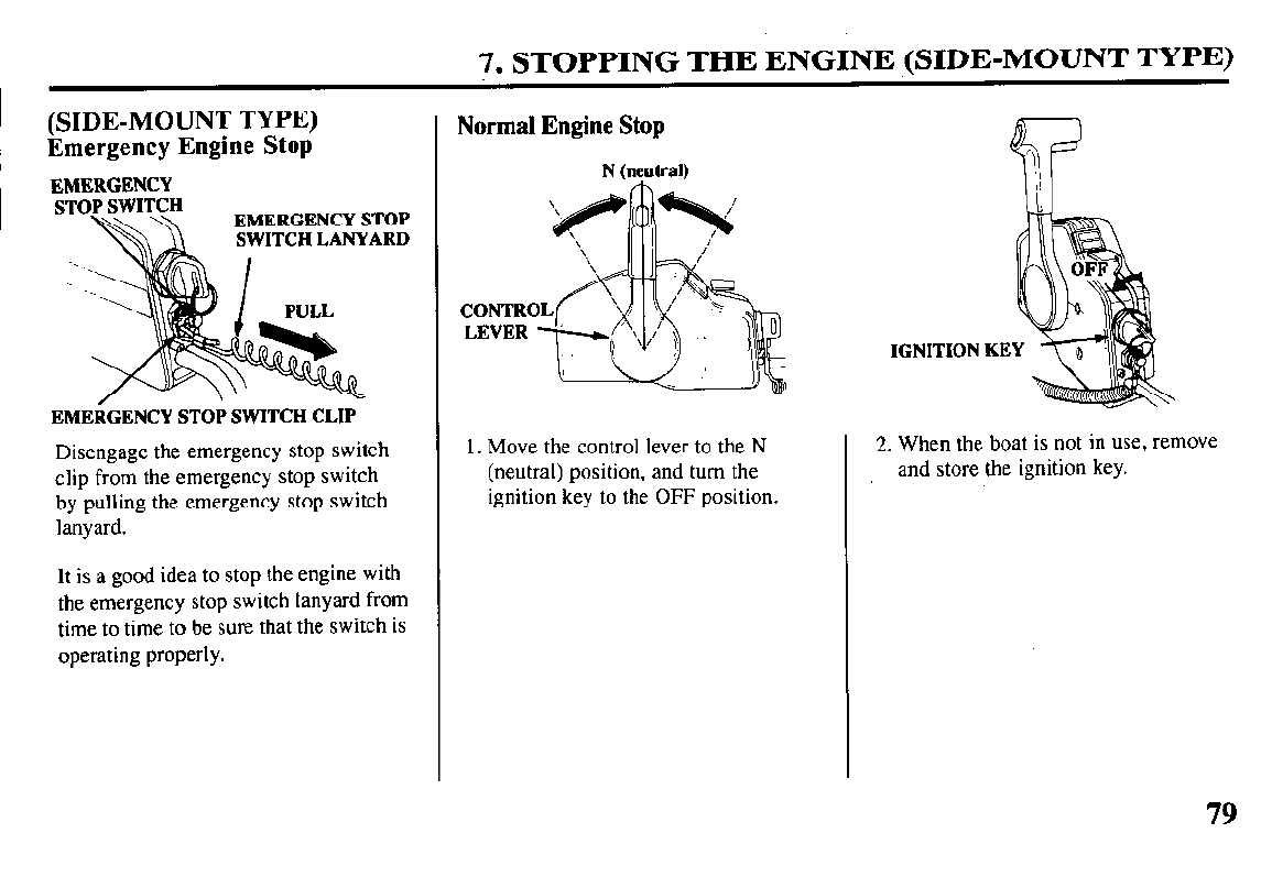
7. STOPPING THE ENGINE (SIDE-MOUNT TYPE)
(SIDE-MOUNT TYPE)
Emergency Engine Stop
EMERGENCY
STOP SWITCH
M\ EMERGENCY STOP
SWITCH LANYARD
EMERGENCY STOP SWITCH CLIP
Disengage the emergency stop switch
clip from the emergency stop switch
by pulling the emergency stop switch
lanyard.
It is a good idea to stop the engine with
the emergency stop switch lanyard from
time to time to be sure that the switch is
operating properly.
Normal Engine Stop
N (neutral)
1. Move the control lever to the N
(neutral) position, and turn the
ignition key to the OFF position.
IGNITION KEY
2. When the boat is not in use, remove
and store the ignition key.
79
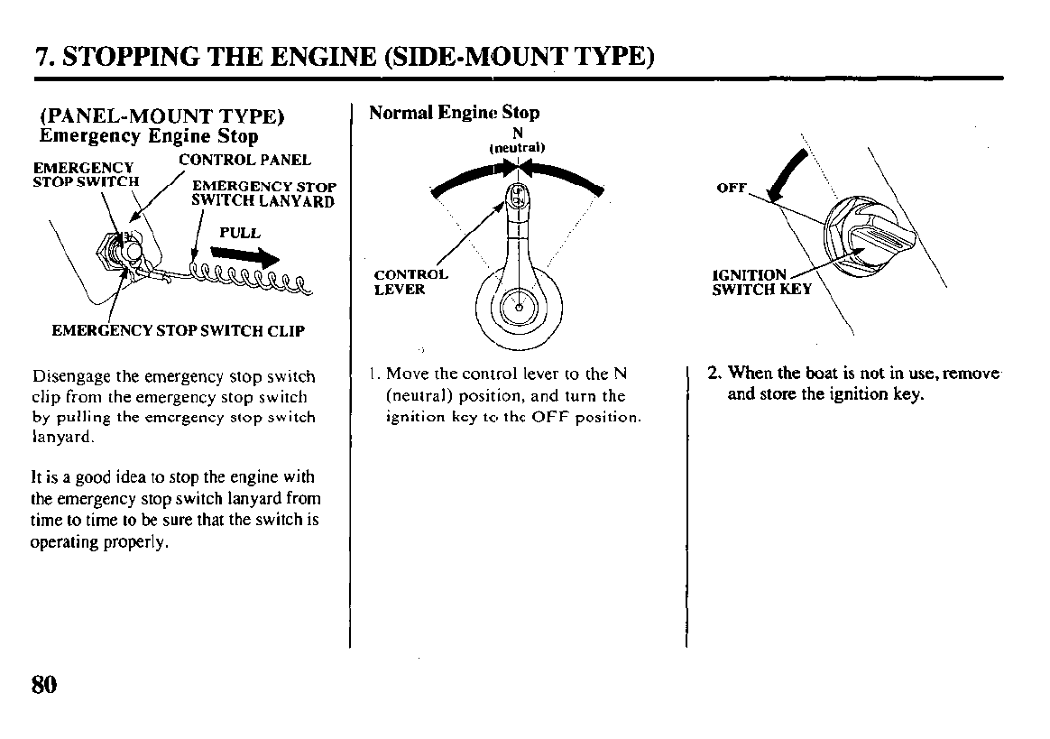
7. STOPPING THE ENGINE (SIDE-MOUNT TYPE)
(PANEL-MOUNT TYPE)
Emergency Engine Stop
EMERdENCY STOP SWITCH CLIP
Disengage the emergency stop switch
clip from the emergency stop switch
by pulling the emergency stop switch
lanyard.
It is a good idea to stop the engine with
the emergency stop switch lanyard from
time to time to be sure that the switch is
operating properly.
Normal Engine Stop
N
Ineutral)
1. Move the control lever to the N
(neutral) position, and turn the
ignition key to the OFF position.
2.
When
the boat is not in use, remove
and store the ignition key.
80
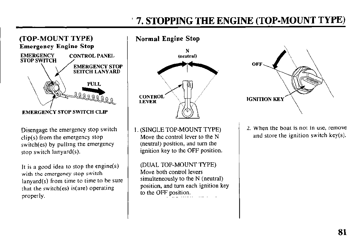
’ 7. STOPPING THE ENGINE (TOP-MOUNT TYPE)
(TOP-MOUNT TYPE)
Emergency Engine Stop
EMERGENCY
STOP SWITCH
\
CONTROL PANEL
EMERGENCY STOP
SEITCH LANYARD
EMERGENCY STOP SWITCH CLIP
Disengage the emergency stop switch 1. (SINGLE TOP-MOUNT TYPE)
clip(s) from the emergency stop Move the control lever to the N
switch(es) by pulling the emergency (neutral) position, and turn the
stop switch lanyard(s). ignition key to the OFF position.
It is a good idea to stop the engine(s)
with the emergency stop switch
lanyard(s) from time to time to be sure
that the switch(es) is(are) operating
properly.
Normal Engine Stop
N
(neutral)
(DUAL TOP-MOUNT TYPE)
Move both control levers
simulteneously to the N (neutral)
position, and turn each ignition key
to the OFF position.
OFF
IGNITION KEY
2. When the boat is not in use, remove
and store the ignition switch key(s).
81
8. TRANSPORTING
Before transporting the outboard motor,
close the fuel cap vent knob (refer to page
38) and disconnect the fuel coupling from
the outboard motor (refer to page 50).
Trailering
When trailering or transporting the
boat with the motor attached, it is
recommended that the motor remain
in the normal run position.
Use a motor support bar (refer to your
motor support bar manufacturer’s
instructions) to stop the motor’s side-
to-side movement.
If there is insufficient road clearance
with the motor in the normal run
position, then trailer the motor in the
tilted position using a commercially
available motor support bar (refer to
your motor support bar manufacrurer’s
instructions) or remove the motor from
the boat.
82
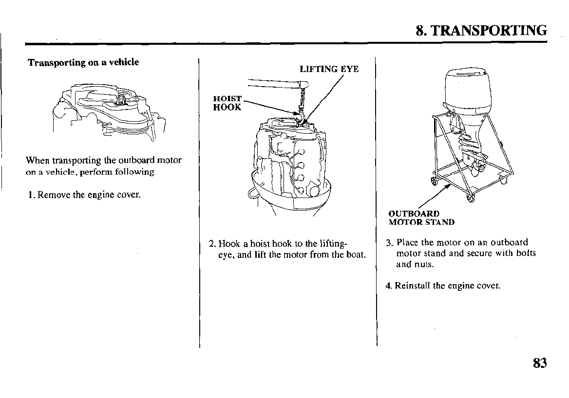
8. TRANSPORTING
Transporting on a vehicle
When transporting the outboard motor
on a vehicle, perform following.
1. Remove the engine cover.
HOIST
HOOK
LIFTING EYE
2. Hook a hoist hook to the lifting-
eye, and lift the motor from the boat.
OUTBdARD
MOTOR STAND
3. Place the motor on an outboard
motor stand and secure with bolts
and nuts.
4. Reinstall the engine cover.
83
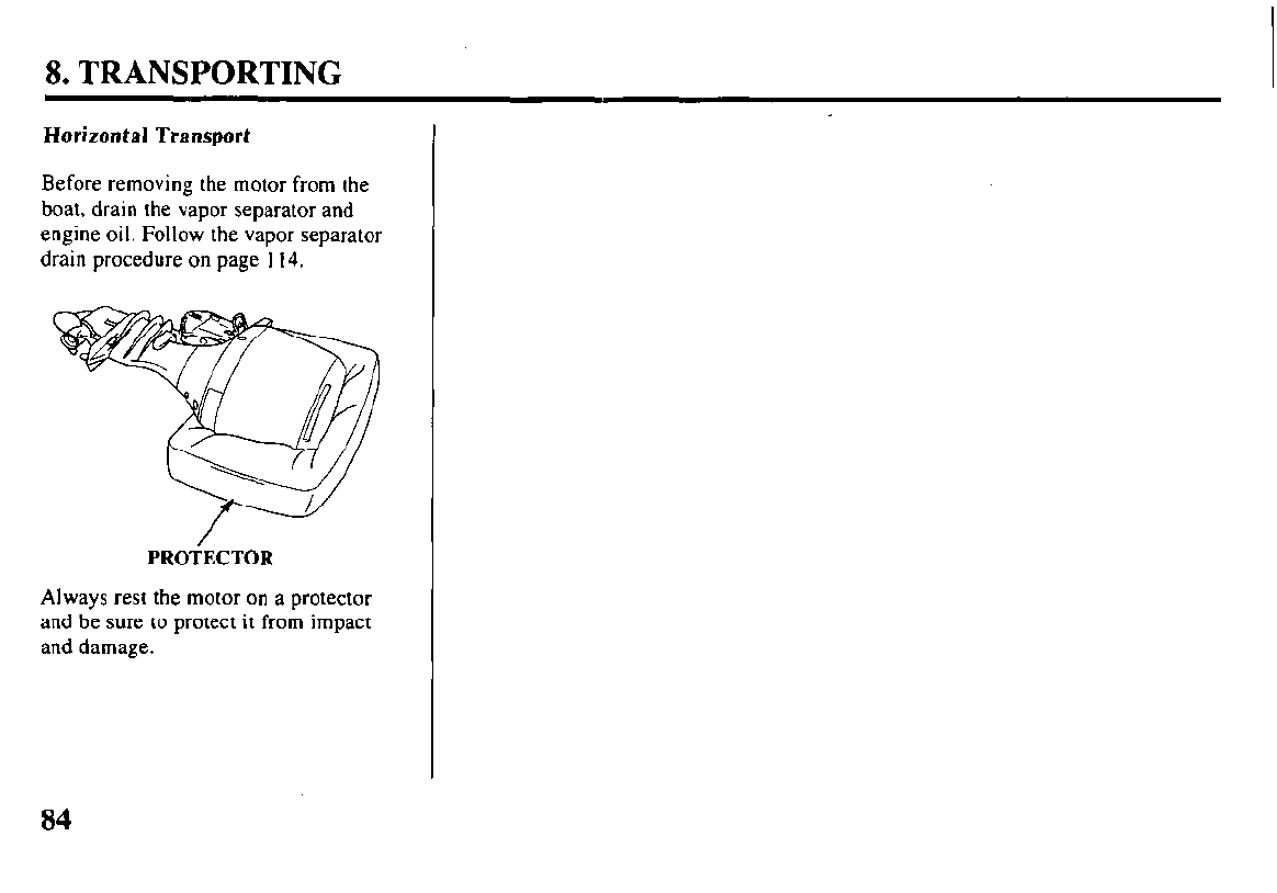
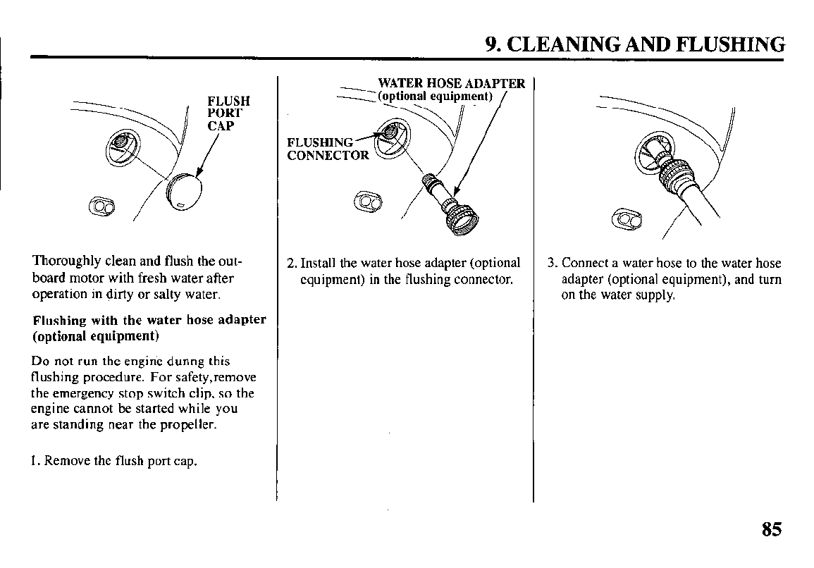
9. CLEANING AND FLUSHING
Thoroughly clean and flush the out-
board motor with fresh water after
operation in dirty or salty water.
Flushing with the water hose adapter
(optional equipment)
Do not run the engine dunng this
flushing procedure. For safety,remove
the emergency stop switch clip, so the
engine cannot be started while you
are standing near the propeller.
1. Remove the flush port cap.
WATER HOSE ADAPTER
2 (optional equipment)
2. Install the water hose adapter (optional
equipment) in the flushing connector. 3. Connect a water hose to the water hose
adapter (optional equipment), and turn
on the water supply.
85
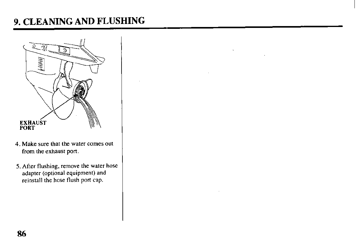
9. CLEANING AND FLUSHING
PORT \I\’ \
4. Make sure that the water comes out
from the exhaust port.
5. After flushing, remove the water hose
adapter (optional equipment) and
reinstall the hose flush port cap.
86
I 10. MAINTENANCE
THE IMPORTANCE OF
MAINTENANCE
Good maintenance is essential for safe,
economical, and trouble-free opera-
tion. It will also help reduce pollution.
m Improperly maintain-
ing this outboard motor, or failure
to correct a problem before
operation, can cause a malfunction
in which you can be seriously
hurt or killed.
Always follow the inspection
and maintenance recommen da-
tions and schedules in this
owner’s manual.
To help you properly care for your
outboard motor, the following pages
include a maintenance schedule,
routine inspection procedures, and
simple maintenance procedures using
basic hand tools. Other service tasks
that are more difficult, or require
special tools, are best handled by
professionals and are normally per-
formed by a Honda technician or other
qualified mechanic.
The maintenance schedule applies to
normal operating conditions. If you
operate your outboard motor under
unusual conditions, consult your
servicing dealer for recommendations
applicable to your individual needs
and use.
Remember that your authorized Honda
marine dealer knows your outboard motor
best and is fully equipped to maintain and
repair it.
To ensure the best quality and
reliability, use only new, genuine Honda
parts or their equivalents for repair and
replacement.
Maintenance, replacement, or
repair of the emission control
devices and systems may be
performed by any marine
engine repair establishment or
individual, using parts that are
“certified” to EPA standards.
87
10. MAINTENANCE
MAINTENANCE SAFETY
Some of the most important safety
precautions follow. However, we
cannot warn you of every conceivable
hazard that can arise in performing
maintenance. Only you can decide
whether or not you should perform a
given task.
!!!EZ!2~Et~~~r\Yrly B
tions and precautions can
cause you to be seriously hurt
or killed.
Always follow the procedures
and precautions in this owner’s
manual.
Safety Precautions
l
Make sure the engine is off before
you begin any maintenance or
repairs. This will eliminate several
potential hazards:
- Carbon monoxide poisoning from
engine exhaust.
Be sure there is adequate ventila-
tion whenever you operate the
engine.
- Burns from hot parts.
Let the engine cool before touch-
ing.
- Injury from moving parts.
Do no1 run the engine unless
instructed to do so.
l
Read the instructions before you
begin, and make sure you have the
tools and skills required.
l
To reduce the possibility of fire or
explosion, be careful when working
around gasoline. Use only a non-
flammable solvent, not gasoline to
clean parts. Keep cigarettes, sparks,
and flames away from all fuel-
related parts.
EMISSION CONTROL
SYSTEM INFORMATION
Source of Emissions
The combustion process produces
carbon monoxide, oxides of nitrogen,
and hydrocarbons. Control of hydro-
carbons and oxides of nitrogen is very
important because, under certain
conditions, they react to form photo-
chemical smog when subjected to
sunlight.
Honda utilizes lean PGM-FI and other
systems to reduce the emissions of
oxides of nitrogen and hydrocarbons.
88
10. MAINTENANCE
The U.S. and California Clean Air Acts
EPA and California regulations require all
manufactures to furnish written instruc-
tions describing the operation and main-
tenance of emission control systems.
The following instructions and proce-
dures must be followed in order to
keep the emissions from your Honda
engine within the emission standards.
Tampering and Altering
Tampering with or altering the emis-
sion control system may increase
emissions beyond the legal limit.
Among those acts that constitute
tampering are:
l
Removal or alteration of any part of
the intake, fuel , or exhaust systems.
l
Alterations that would cause the
engine to operate outside its design
parameters.
Problems That May Affect Emissions
If you are aware of any of the
following symptoms, have your engine
inspected and repaired by your servic-
ing dealer.
l
Hard starting or stalling after starting.
l
Rough idle.
l
Misfiring or backfiring under load.
l
Afterburning (backfiring).
l
Black exhaust smoke or high
fuel consumption.
89
10. MAINTENANCE
Replacement Parts
The emission control systems on your
Honda engine were designed, built,
and certified to conform with EPA and
California emission regulations. We reco-
mmend the use of genuine Honda parts
whenever you have maintenance done.
These original-design replacement
parts are manufactured to the same
standards as the original parts, so you
can be confident of their performance.
The use of replacement parts that are
not of the original design and quality
may impair the effectiveness of your
emission control system.
A manufacturer of an aftermarket part
assumes the responsibility that the part
will not adversely affect emission
performance. The manufacturer or
rebuilder of the part must certify that
use of the part will not result in a
failure of the engine to comply with
emission regulations.
Maintenance
Follow the maintenance schedule on
pages 92 and 9.3. Remenber that this
schedule is based on the assumption that
your machine will be used for its designed
purpose. Sustained high-load or high-
temperature operation, or use in
unusually wet or dusty conditions, will
require more frequent service.
90
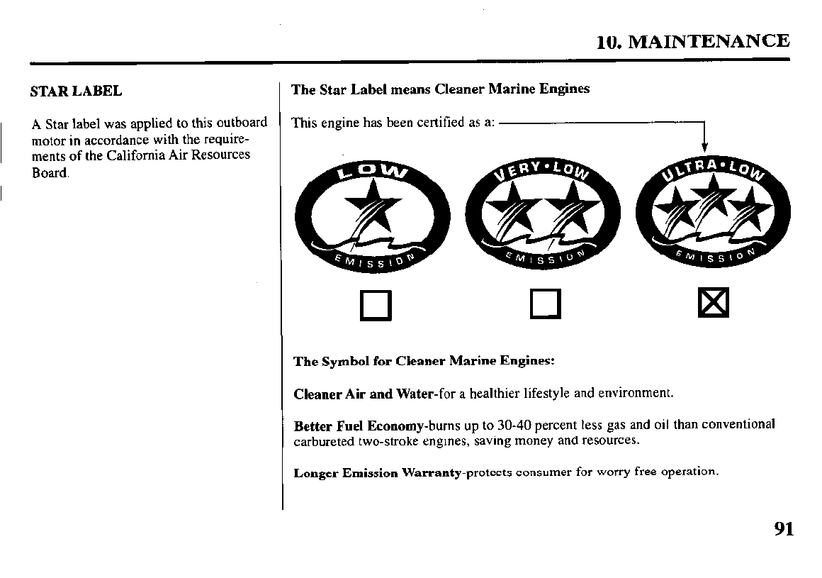
10. MAINTENANCE
STAR LABEL
A Star label was applied to this outboard
motor in accordance with the require-
ments of the California
Air Resources
Board.
The Star Label means Cleaner Marine Engines
This engine has been certified as a: i
a
/ .
0 0
The Symbol for Cleaner Marine Engines:
Cleaner Air and
Water-for
a healthier lifestyle and environment.
Better
Fuel Economy-burns up to 30-40 percent
less gas and oil than conventional
carbureted two-stroke engines, saving money and resources.
Longer Emission
Warranty-protects
consumer for worry free operation.
91
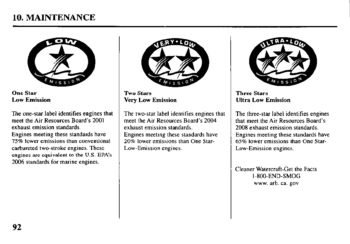
10. MAINTENANCE
One Star Two Stars
Low Emission Very Low Emission
The one-star label identifies engines that
meet the Air Resources Board’s 2001
exhaust emission standards.
Engines meeting these standards have
75% lower emissions than conventional
carbureted two-stroke engines. These
engines are equivalent to the U.S. EPA’s
2006 standards for marine engines.
The two-star label identifies engines that The three-star label identifies engines
meet the Air Resources Board’s 2004 that meet the Air Resources Board’s
exhaust emission standards. 2008 exhaust emission standards.
Engines meeting these standards have Engines meeting these standards have
20% lower emissions than One Star- 65% lower emissions than One Star-
Low-Emission engines. Low-Emission engines.
Three Stars
Ultra Low Emission
Cleaner Watercraft-Get the Facts
I -8OO-END-SMOG
www. arb. ca. gov
92
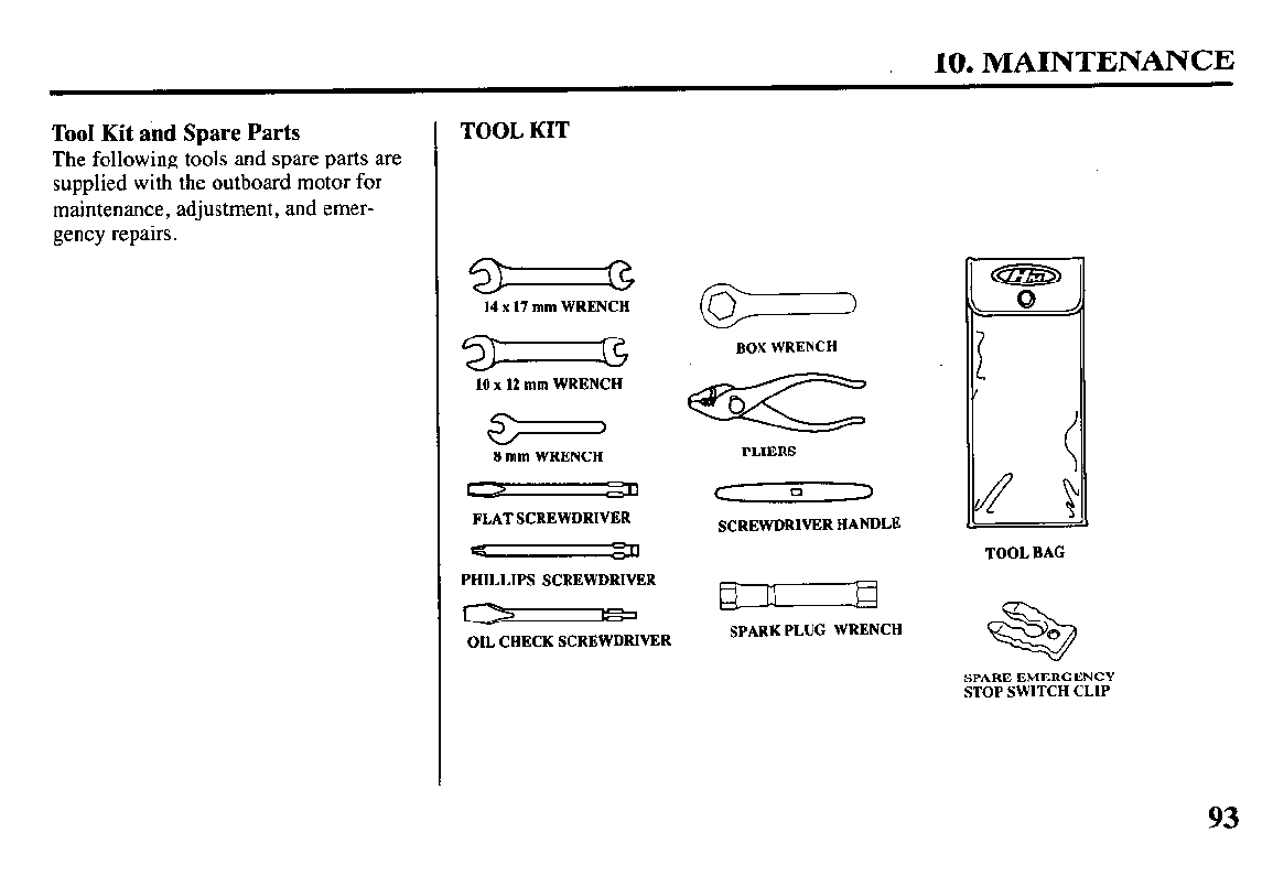
10. MAINTENANCE
Tool Kit and Spare Parts
The following tools and spare parts are
supplied with the outboard motor for
maintenance, adjustment, and emer-
gency repairs.
TOOL KIT
8 mm WRENCH PLIERS
C
0 z
FLAT SCREWDRIVER
PHILLIPS SCREWDRIVER
w
OIL CHECK SCREWDRIVER
SCREWDRIVER HANDLE
SPARK PLUG WRENCH
TOOL BAG
*
0
SPARE EMERGENCY
STOP SWITCH CLIP
93
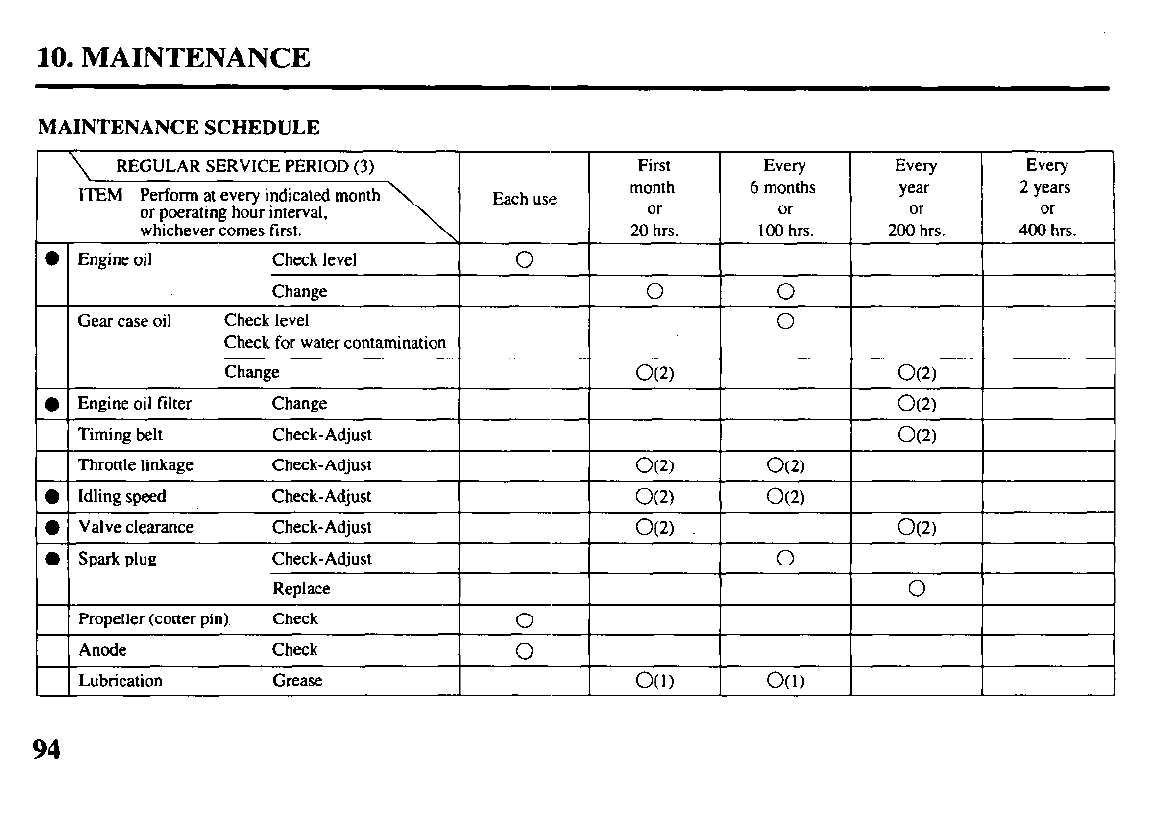
10. MAINTENANCE
MAINTENANCE SCHEDULE
REGULAR SERVICE PERIOD (3)
ITEM Perform at every indicated month
or poerating hour interval,
whichever comes first.
0 Engine oil Check level
Change
Each use
0
First Every
month 6 months
or or
20 hrs. 100 hrs.
0 0
Every
year
or
200 hrs.
Every
2 years
or
400 hrs.
Gear case oil
Check for water contamination
l
Engine oil filter
Timing belt
Throttle linkage
Change
Check-Adjust
Check-Adjust
l
Idling speed Check-Adjust
O(2) O(2)
l
1 Valve clearance Check-Adjust I I
O(2) I I O(2) I
0 spark plug Check-Adjust
Replace
0
0
Propeller (cotter pin) Check
0
I 0 I
Lubrication Grease O(l) O(1)
94
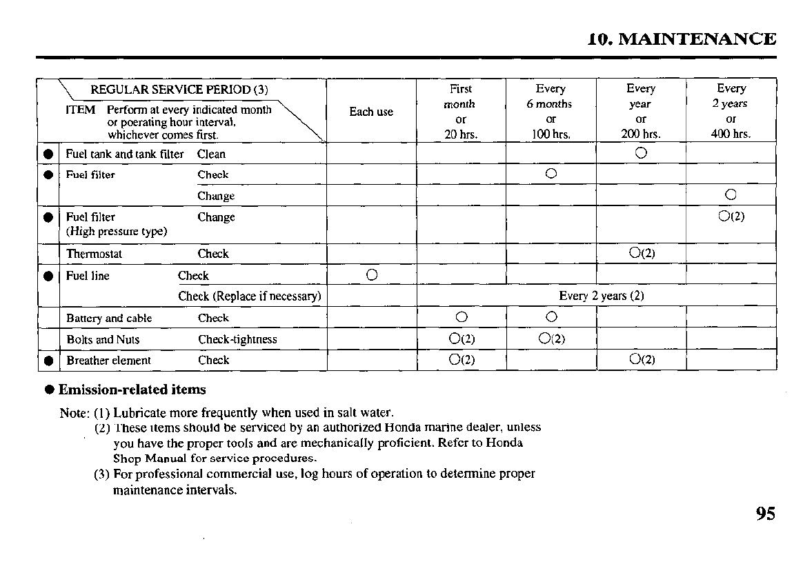
10. MAINTENANCE
REGULAR SERVICE PERIOD (3) First Every Every
ITEM Perform at every indicated month Each use month 6 months year
or poerating hour interval, or or or
whichever comes first. 20 hrs. 100 hrs. 200 hrs.
0 Fuel tank and tank filter Clean
0
0 Fuel filter Check
0
Change
l Fuel filter Change
(High pressure type)
Thermostat Check O(2)
l Fuel line Check
0
Check (Replace if necessary) Every 2 years (2)
Battery and cable Check
0 0
Bolts and Nuts Check-tightness O(2) O(2)
l Breather element Check O(2) O(2)
0 Emission-related items
Note: (1) Lubricate more frequently when used in salt water.
(2) These items should be serviced by an authorized Honda marine dealer, unless
you have the proper tools and are mechanically proficient. Refer to Honda
Shop Manual for service procedures.
(3) For professional commercial use, log hours of operation to determine proper
maintenance intervals.
Every
2 years
Or
400 hrs.
0
O(2)
95
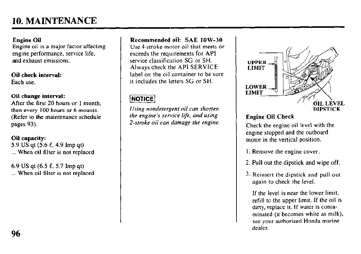
10. MAINTENANCE
Engine Oil
Engine oil is a major factor affecting
engine performance, service life,
and exhaust emissions.
Oil check interval:
Each use.
Oil change interval:
After the first 20 hours or 1 month,
then every 100 hours or 6 mounts.
(Refer to the maintenance schedule
pages 93).
Oil capacity:
5.9 US qt (5.6 e, 4.9 Imp qt)
. . . When oil filter is not replaced
6.9 US qt (6.5 e, 5.7 Imp qt)
. . . When oil filter is not replaced
Recommended oil: SAE low-30
Use 4-stroke motor oil that meets or
exceeds the requirements for API
service classification SG or SH.
Always check the API SERVICE
label on the oil container to be sure
it includes the letters SC or SH.
Using nondetergent oil can shorten
the engine’s service life, and using
2-stroke oil can damage the engine.
/l’ dlL LEVEL
DIPSTICK
Engine Oil Check
Check the engine oil level with the
engine stopped and the outboard
motor in the vertical position.
1. Remove the engine cover.
2. Pull out the dipstick and wipe off.
3. Reinsert the dipstick and pull out
again to check the level.
If the level is near the lower limit,
refill to the upper limit. If the oil is
dirty, replace it. If water is conta-
minated (it becomes white as milk),
see your authorized Honda marine
dealer.
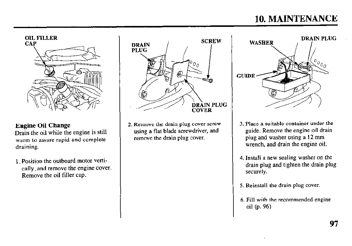
10. MAINTENANCE
OIL FILLER
CAP
Engine Oil Change
Drain the oil while the engine is still
warm to assure rapid and complete
draining.
I. Position the outboard motor verti-
cally, and remove the engine cover.
Remove the oil filler cap.
2. Remove the drain plug cover screw
using a flat blade screwdriver, and
remove the drain plug cover.
WASHER
GUIDE
3. Place a suitable container under the
guide. Remove the engine oil drain
plug and washer using a 12 mm
wrench, and drain the engine oil.
4. Install a new sealing washer on the
drain plug and tighten the drain plug
securely.
5. Reinstall the drain plug cover.
6. Fill with the recommended engine
oil (p. 96)
97
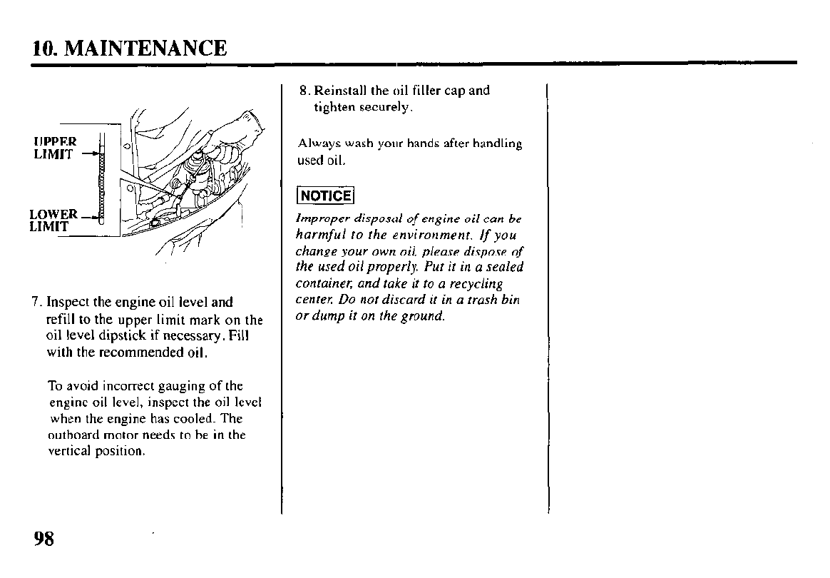
10. MAINTENANCE
UPPER
LIMIT
LOWER
LIMIT
7. Inspect the engine oil level and
refill to the upper limit mark on the
oil level dipstick if necessary. Fill
with the recommended oil.
To avoid incorrect gauging of the
engine oil level, inspect the oil level
when the engine has cooled. The
outboard motor needs to be in the
vertical position.
8. Reinstall the oil filler cap and
tighten securely.
Always wash your hands after handling
used oil.
Improper disposal
of
engine oil can be
harmful to the environment. If you
change your own oil, please dispose of
the used oil properly. Put it in a sealed
container; and take it to a recycling
center Do not discard it in a trash bin
or dump it on the ground.
98
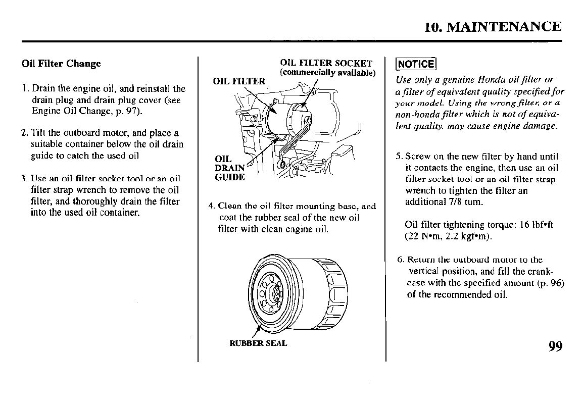
10. MAINTENANCE
Oil Filter Change
1. Drain the engine oil, and reinstall the
drain plug and drain plug cover (see
Engine Oil Change, p. 97).
2. Tilt the outboard motor, and place a
suitable container below the oil drain
guide to catch the used oil
3. Use an oil filter socket tool or an oil
filter strap wrench to remove the oil
filter, and thoroughly drain the filter
into the used oil container.
OIL FILTER SOCKET
(commercially available)
4. Clean the oil filter mounting base, and
coat the rubber seal of the new oil
filter with clean engine oil.
RUBBER SEAL
Use only a genuine Honda oil filter or
a jilter of equivalent quality specified for
your model. Using the wrong Jilter; or a
non-honda filter which is not of equiva-
lent quality, may cause engine damage.
5. Screw on the new filter by hand until
it contacts the engine, then use an oil
filter socket tool or an oil filter strap
wrench to tighten the filter an
additional 7/8 turn.
Oil filter tightening torque: 16 lbf*ft
(22 Nom, 2.2 kgf*m).
6. Return the outboard motor to the
vertical position, and fill the crank-
case with the specified amount (p. 96)
of the recommended oil.
99
10. MAINTENANCE
7. Start the engine, and check for leaks.
Running the engine without water
can cause serious engine damage.
If
you are changing the oilfilter while
the outboard motor is out of the water;
use the water hose adapter (optional
equipment) and a hose (p. 85) to
supply water:
8. Stop the engine, and check the oil
level as described on page 96. If
necessary, add oil to bring the oil level
to the upper limi; mark on the
dipstick.
100
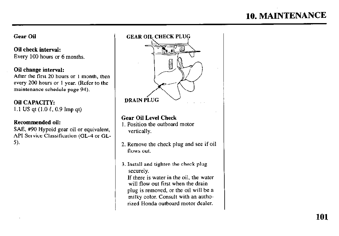
10. MAINTENANCE
Gear Oil
Oil check interval:
Every 100 hours or 6 months.
Oil change interval:
After the first 20 hours or 1 month, then
every 200 hours or 1 year. (Refer to the
maintenance schedule page 94).
Oil CAPACITY:
1.1 US qt (1.0 e, 0.9 Imp qt)
Recommended oil:
SAE, #90 Hypoid gear oil or equivalent,
API Service Classification (CL-4 or GL-
5).
GEAR OIL CHECK PLUG
DRAIN PLUG
Gear Oil Level Check
1. Position the outboard motor
vertically.
2. Remove the check plug and see if oil
flows out.
3. Install and tighten the check plug
securely.
If there is water in the oil, the water
will flow out first when the drain
plug is removed, or the oil will be a
milky color. Consult with an autho-
rized Honda outboard motor dealer.
101
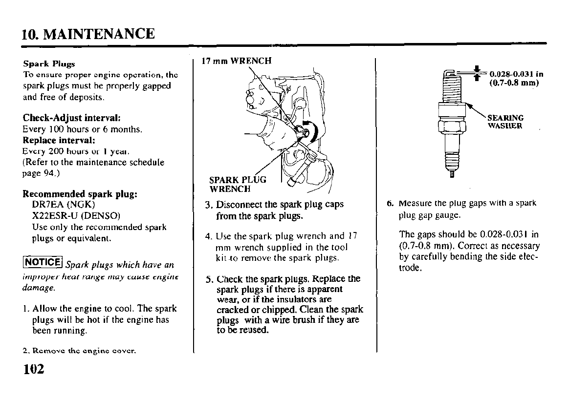
10. MAINTENANCE
Spark Plugs
To ensure proper engine operation, the
spark plugs must be properly gapped
and free of deposits.
Check-Adjust interval:
Every 100 hours or 6 months.
Replace interval:
Every 200 hours or 1 year.
(Refer to the maintenance schedule
page 94.)
Recommended spark plug:
DR7EA (NGK)
X22ESR-U (DENSO)
Use only the recommended spark
plugs or equivalent.
lNoTlCEl Spark plugs which have an
improper heat range may cause engine
damage.
1. Allow the engine to cool. The spark
plugs will be hot if the engine has
been running.
2. Remove the engine cover.
102
17 mm WRENCH
SPARK PLUG
WRENCH
3. Disconnect the spark plug caps
from the spark plugs.
4. Use the spark plug wrench and 17
mm wrench supplied in the tool
kit .to remove the spark plugs.
5. Check the spark plugs. Replace the
spark plugs if there is apparent
wear, or if the insulators are
cracked or chipped. Clean the spark
plugs with a wire brush if they are
to be reused.
0.028-0.031 in
(0.7-0.8 mm)
’ SEARING
WASHER ,
6. Measure the plug gaps with a spark
plug gap gauge.
The gaps should bc 0.028-0.03 I in
(0.7-0.8 mm). Correct as necessary
by carefully bending the side elec-
trode.
ZFR7F (NGK); KJ22CR-L8 (DENSO)
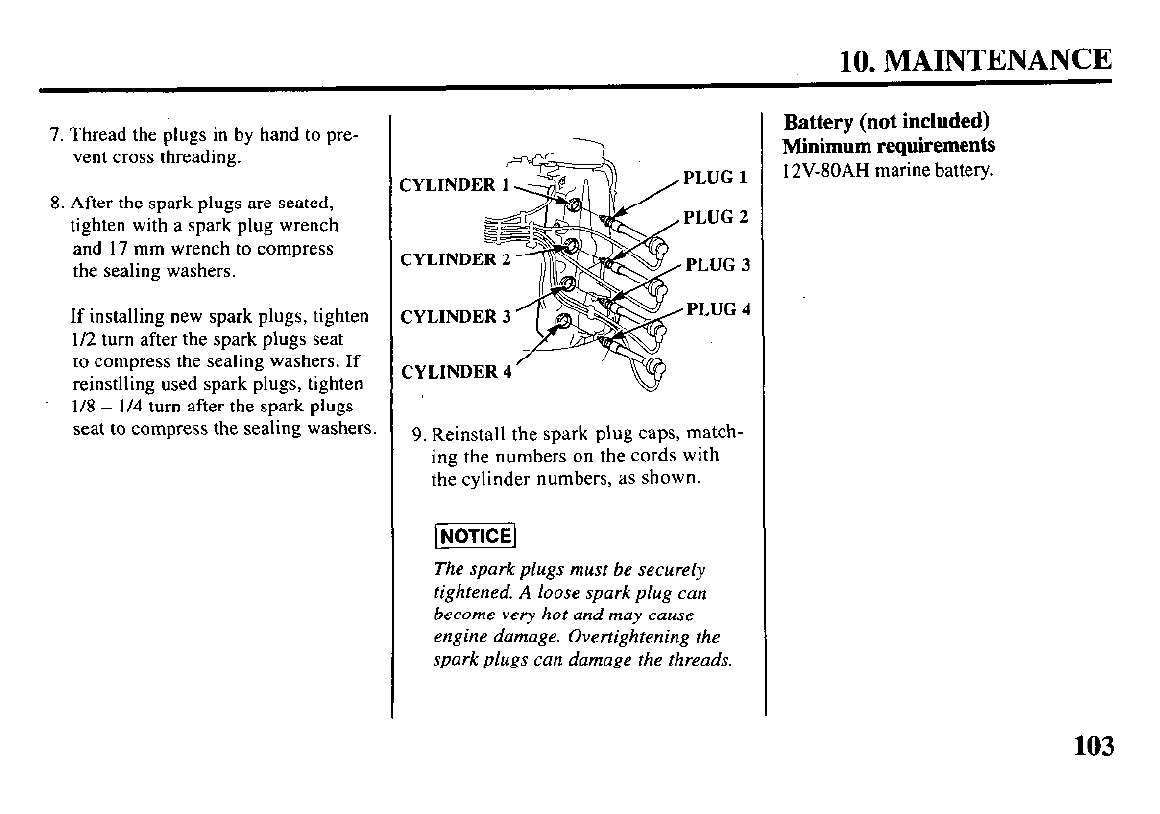
10. MAINTENANCE
7. Thread the plugs in by hand to pre-
vent cross threading.
8. After the spark plugs are seated,
tighten with a spark plug wrench
and 17 mm wrench to compress
the sealing washers.
If installing new spark plugs, tighten
112 turn after the spark plugs seat
to compress the sealing washers. If
reinstlling used spark plugs, tighten
l/8 - l/4 turn after the spark plugs
seat to compress the sealing washers.
JYLINDER ; PLUG 1
PLUG 2
PLUG 3
PLUG 4
CYLINDER 4
9. Reinstall the spark plug caps, match-
ing the numbers on the cords with
the cylinder numbers, as shown.
The spark plugs must be securely
tightened. A loose spark plug can
become very hot and may cause
engine damage. Overtightening the
spark plugs can damage the threads.
Battery (not included)
Minimum requirements
12V-80AH marine battery.
103
10. MAINTENANCE
To protect the battery from mechani-
cal damage and to prevent the bat-
tery from falling or tipping over, the
battery must be:
l Installed in the correct size corro-
sion-resistant battery box.
l Properly secured in the boat.
l Secured in a location free from di-
rect sunlight and water spray.
l Secured away from the fuel tank
to avoid potential sparks near the
fuel tank.
1. Install the battery in the battery box.
2. Connect the positive (+) battery
cable first, then connect the nega-
tive (-) battery cable. Tighten the
cable nuts securely.
3. Coat the battery terminals and ca-
ble ends with marine anticor-
rosion grease.
4. Put the cover on the battery box,
and secure the battery box to the
boat.
104
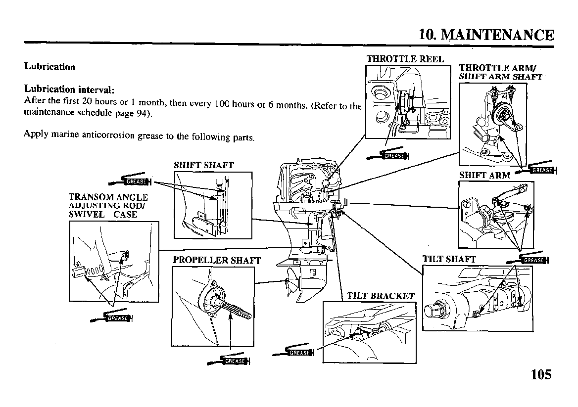
10. MAINTENANCE
Lubrication THROTTLE REEL THROTTLE ARM/
SHIFT ARM SHAFT
Lubrication interval:
After the first 20 hours or 1 month, then every 100 hours or 6 months. (Refer to the
maintenance schedule page 94).
Apply marine anticorrosion grease to the following parts.
TRANSOM ANGLE
ADJUSTING ROD/
SWIVEL CASE
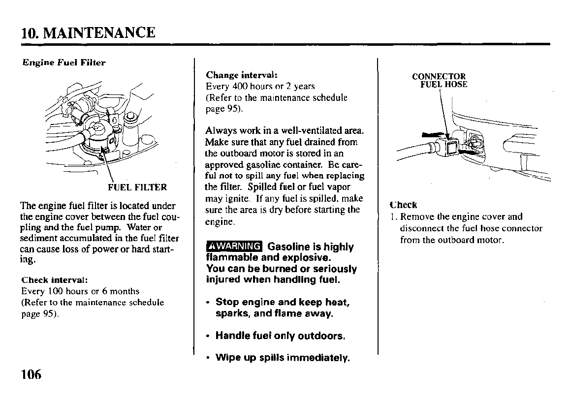
10. MAINTENANCE
Engine Fuel Filter
’ \
FUEL FILTER
The engine fuel filter is located under
the engine cover between the fuel cou-
pling and the fuel pump. Water or
sediment accumulated in the fuel filter
can cause loss of power or hard start-
ing.
Check interval:
Every 100 hours or 6 months
(Refer to the maintenance schedule
page 95).
Change intervak:
Every 400 hours or 2 years
(Refer to the maintenance schedule
page 95).
Always work in a well-ventilated area.
Make sure that any fuel drained from
the outboard motor is stored in an
approved gasoline container. Be care-
ful not to spill any fuel when replacing
the filter. Spilled fuel or fuel vapor
may ignite. If any fuel is spilled, make
sure the area is dry before starting the
engine.
m Gasoline is
highly
A -
flammable and explosive. - -
You can be burned or seriously
injured when handling fuel.
l
Stop engine and keep heat,
sparks, and flame away.
l
Handle fuel only outdoors.
l
Wipe up spills immediately.
CONNECTOR
FUE\ HOSE
Check
1. Remove the engine cover and
disconnect the fuel hose connector
from the outboard motor.
106
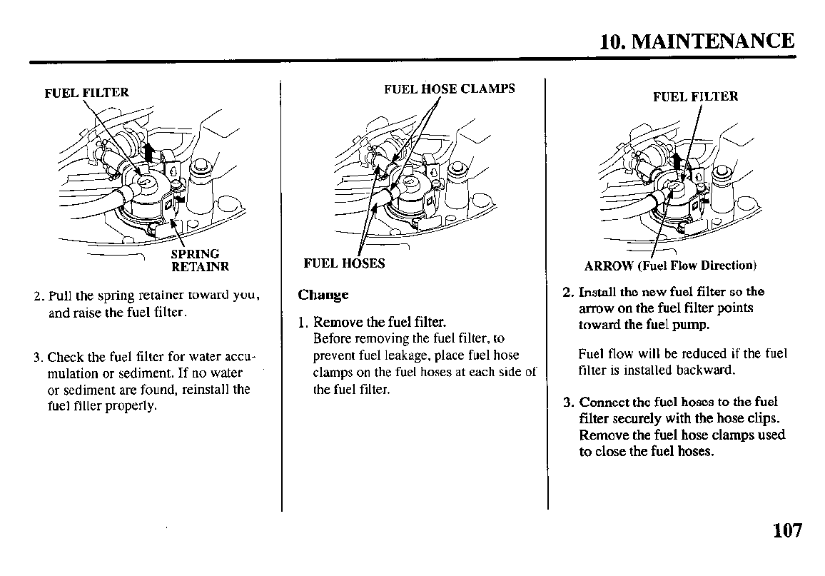
10. MAINTENANCE
FUEL FILTER
‘I
SPRING
RETAINR
2. Pull the spring retainer toward you,
and raise the fuel filter.
3.
Check the fuel filter for water accu-
mulation or sediment. If no water
or sediment are found, reinstall the
fuel filler properly.
FUEL HOSE CLAMPS
Y \
FUEL HOSES
Change
1. Remove the fuel filter.
Before removing the fuel filter, to
prevent fuel leakage, place fuel hose
clamps on the fuel hoses at each side of
the fuel filter.
FUEL FILTER
ARROW (Fbel Flow Direction)
2. Install the new fuel filter so the
arrow on the fuel filter points
toward the fuel pump.
Fuel flow will be reduced if the fuel
filter is installed backward.
3.
Connect the fuel
hoses to the fuel
filter
securely with the hose clips.
Remove the fuel hose clamps used
to close the fuel hoses.
107
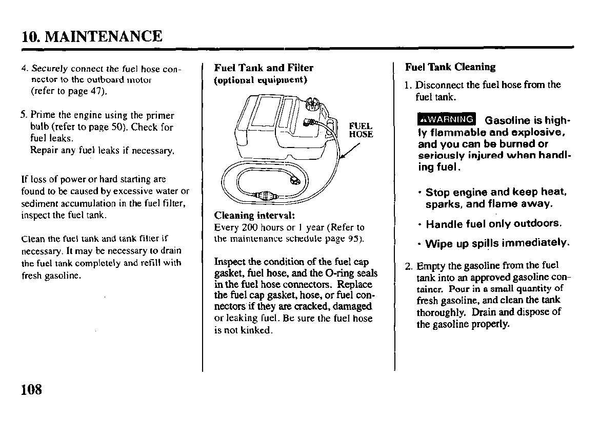
10. MAINTENANCE
4. Securely connect the fuel hose con-
nector to the outboard motor
(refer to page 47).
5. Prime the engine using
the primer
bulb (refer to page 50). Check for
fuel leaks.
Repair any fuel leaks if necessary.
If loss of power or hard starting are
found to be caused by excessive water or
sediment accumulation in the fuel filter,
inspect the fuel tank.
Clean the fuel tank and tank filter if
necessary.
It may be necessary to drain
the
fuel tank completely and refill with
fresh gasoline.
Fuel Tank and Filter
(optional
equipment)
FUEL
HOSE
/
Cleaning interval:
Every 200 hours or I year (Refer to
the maintenance schedule page 95).
Inspect the condition of the fuel cap
gasket, fuel hose, and the O-ring seals
in the fuel hose connectors. Replace
the fuel cap gasket, hose, or fuel con-
nectors if they are cracked, damaged
or leaking fuel. Be sure the fuel hose
is not kinked.
Fuel ‘lhk Cleaning
1. Disconnect the fuel hose from the
fuel tank.
B Gasoline is high-
ly flammable and explosive,
and you can be burned or
seriously injured when handl-
ing fuel.
l
Stop engine and keep heat,
sparks, and flame away.
l
Handle fuel only outdoors.
l
Wipe up spi!ls immediately.
2. Empty the gasoline from the fuel
tank into an approved gasoline con-
tainer. Pour in a small quantity of
fresh gasoline, and clean the tank
thoroughly. Drain and dispose of
the gasoline properly.
108
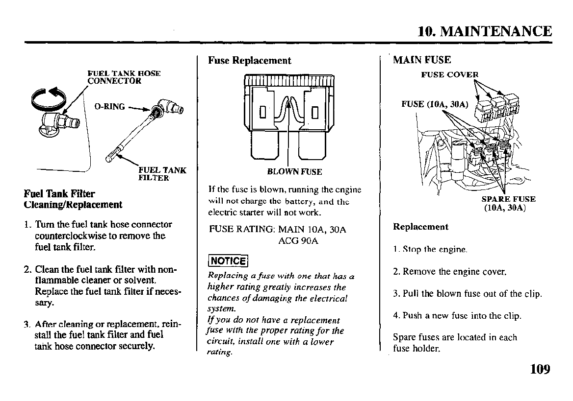
10. MAINTENANCE
FUELTANKHOSE
CONNECTOR
Fuel Tank Filter
Cleaning/Replacement
1. Turn the fuel tank hose connector
counterclockwise to remove the
fuel tank filter.
2. Clean the fuel tank filter with non-
flammable cleaner or solvent.
Replace the fuel tank filter if neces-
sary.
3.
After cleaning
or replacement, rein-
stall the fuel tank filter and fuel
tank hose connector securely.
Fuse Replacement
BLOWNFUSE
If the fuse is blown, running the engine
will not charge the battery, and the
electric starter will not work.
FUSE RATING:
MAIN lOA, 30A
ACG 90A
Replacing a fuse with one that has a
higher rating greatly increases the
chances of damaging the electrical
system.
If
you do not have a replacement
fuse with the proper rating for the
circuit, install one with a lower
rating.
MAIN FUSE
FUSECOVER
SPAREFUSE
(lOA,30A)
Replacement
1. Stop the engine.
2. Remove the engine cover.
3.
Pull the blown fuse out of the clip.
4. Push a new fuse into the clip.
Spare fuses are located in each
fuse holder.
109
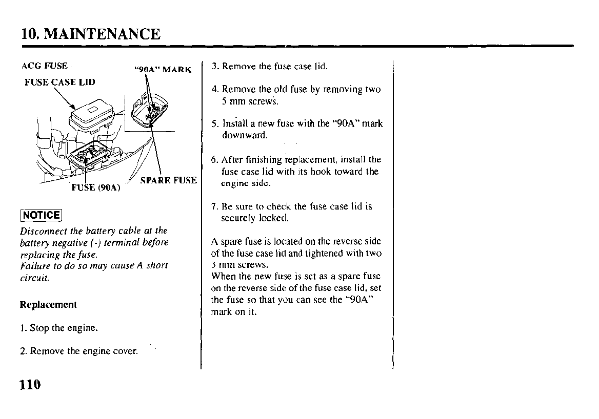
10. MAINTENANCE
ACG FUSE
“90A” MARK
FUSE CASE LID h
USE
FUSE (90A)
Disconnect the battery cable at the
battery negative (-) terminal before
replacing the fuse.
Failure to do so may cause A short
circuit.
Replacement
1. Stop the engine.
2. Remove the engine cover.
3. Remove the fuse case lid.
4. Remove the old fuse by removing two
5 mm screws.
5. Install a new fuse with the “90A” mark
downward.
6. After finishing replacement, install the
fuse case lid with its hook toward the
engine side.
7. Be sure to check the fuse case lid is
securely locked.
A spare fuse is located on the reverse side
of the fuse case lid and tightened with two
3 mm screws.
When the new fuse is set as a spare fuse
on the reverse side of the fuse case lid, set
the fuse so that you can see the “90A”
mark on it.
110
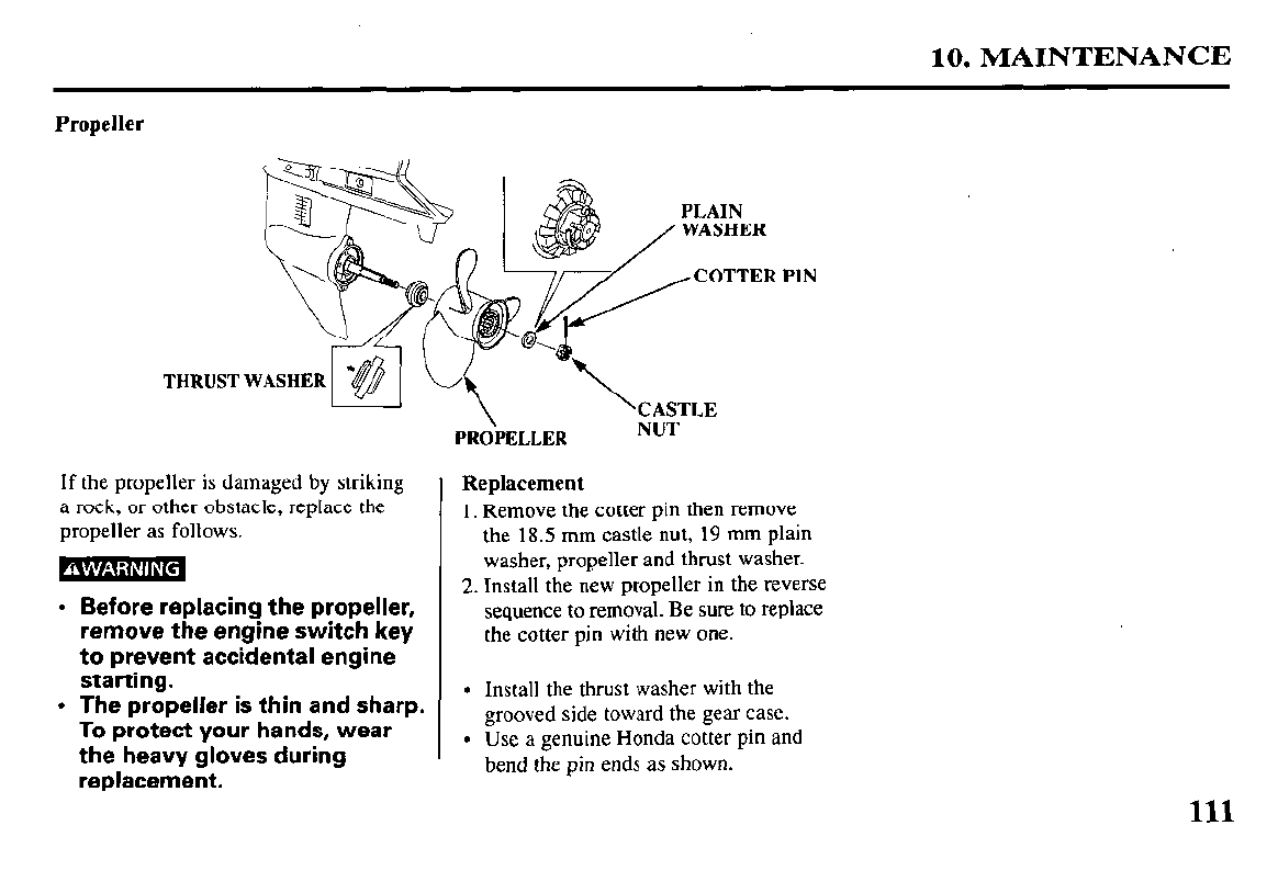
10. MAINTENANCE
Propeller
PLAIN
COTTER PIN
THRUST WASHER
=lCASTLE
PROPELLER NUT
If the propeller is damaged by striking
a rock, or other obstacle, replace the
propeller as follows.
Replacement
1. Remove the cotter pin then remove
the 18.5 mm castle nut, 19 mm plain
washer, propeller and thrust washer.
Install the new propeller in the reverse
sequence to removal. Be sure to replace
the cotter pin with new one.
Before replacing the propeller,
remove the engine switch key
to prevent accidental engine
starting.
The propeller is thin and sharp.
To protect your hands, wear
the heavy gloves during
replacement.
Install the thrust washer with the
grooved side toward the gear case.
Use a genuine Honda cotter pin and
bend the pin ends as shown.
111
10. MAINTENANCE
Submerged Motor
A submerged motor must he serv-
iced immediately after it is recov-
ered from the water in order to
minimize corrosion.
Immediately take the outboard mo-
tor to the closest authorized Honda
Marine dealer or if you are far from
a dealership, proceed as follows:
I. Remove the engine cover, and
rinse the motor with fresh water
to remove salt water, sand, mud,
etc.
2. Drain the vapor separator.
3. Change the engine oil (refer to page 96).
4. Remove the spark plugs.
5. Put a teaspoon of engine oil into
each spark plug hole to lubricate
the inside of the cylinders.
Reinstall the spark plugs.
6. Attempt to start the engine (be sure the
water level is at least 2 inches above the
antiventilation plate).
Running the outboard motor
without sufficient cooling water
will damage the water pump
and overheat the engine.
l If the engine fails to start, re-
move the spark plugs, clean
and dry the electrodes, then re-
install the spark plugs and at-
tempt to start the engine again.
l If the engine starts, and no me-
chanical damage is evident,
continue to run the engine for a l/2
hour or longer.
112
10. MAINTENANCE
l If there was water in the engine
crankcase, or the drained used
engine oil showed signs of water
contamination, then a second
engine oil change should be
performed after running the engine
for a l/2 hour.
7. Take the outboard motor to your
closest authorized Honda Marine
dealer for inspection and service
as soon as possible.
113
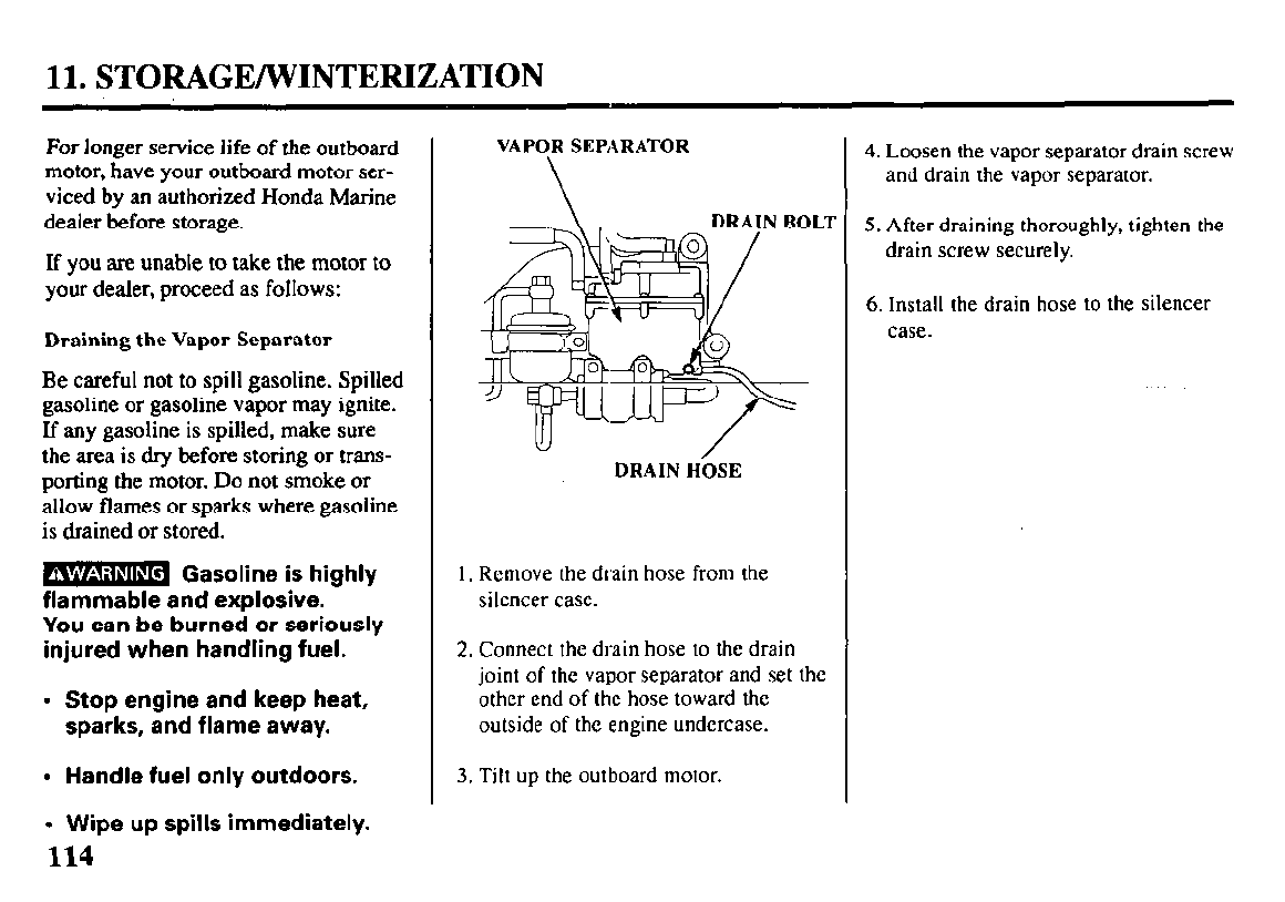
11. STORAGE/WINTEFUZATION
For longer service life of the outboard
motor, have your outboard motor ser-
viced by an authorized Honda Marine
dealer before storage.
If you are unable to take the motor to
your dealer, proceed as follows:
Draining the Vapor Separator
Be careful not to spill gasoline. Spilled
gasoline or gasoline vapor may ignite.
If any gasoline is spilled, make sure
the area is dry before storing or trans-
porting the motor. Do not smoke or
allow flames or sparks where gasoline
is drained or stored.
m Gasoline is highly
flammable and explosive.
You can be burned or seriously
injured when handling fuel.
l
Stop engine and keep heat,
sparks, and flame away.
l
Handle fuel only outdoors.
VAPOR SEPARATOR
DRAIN H&E
I. Remove the drain hose from the
silencer case.
2. Connect the drain hose to the drain
joint of the vapor separator and set the
other end of the hose toward the
outside of the engine undercase.
3. Tilt up the outboard motor.
4. Loosen the vapor separator drain screw
and drain the vapor separator.
5. After draining thoroughly, tighten the
drain screw securely.
6. Install the drain hose to the silencer
case.
l
Wipe up spills immediately.
114
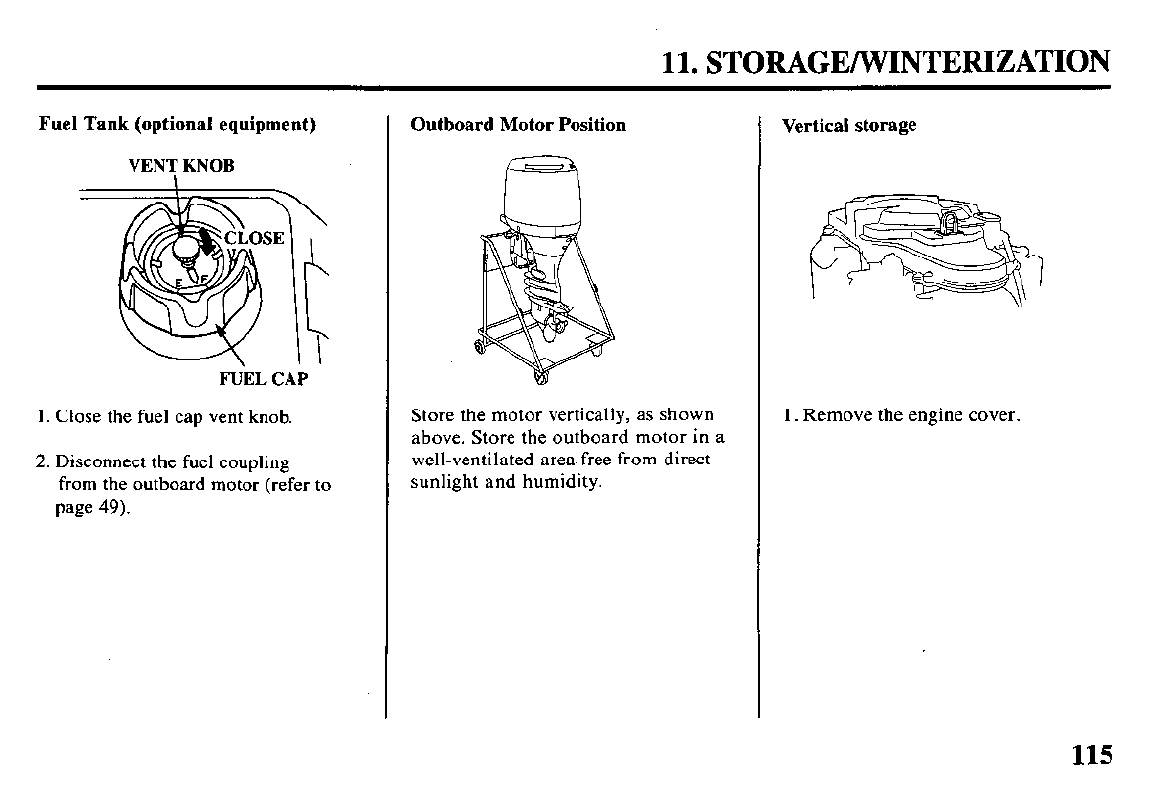
11. STORAGE/WINTERIZATION
Fuel Tank (optional equipment)
VENT KNOB
F&L CAP
1. Close the fuel cap vent knob.
2. Disconnect the fuel coupling
from the outboard motor (refer to
page 49).
Outboard Motor Position
Store the motor vertically, as shown
above. Store the outboard motor in a
well-ventilated area free from direct
sunlight and humidity.
Vertical storage
1. Remove the engine cover.
115
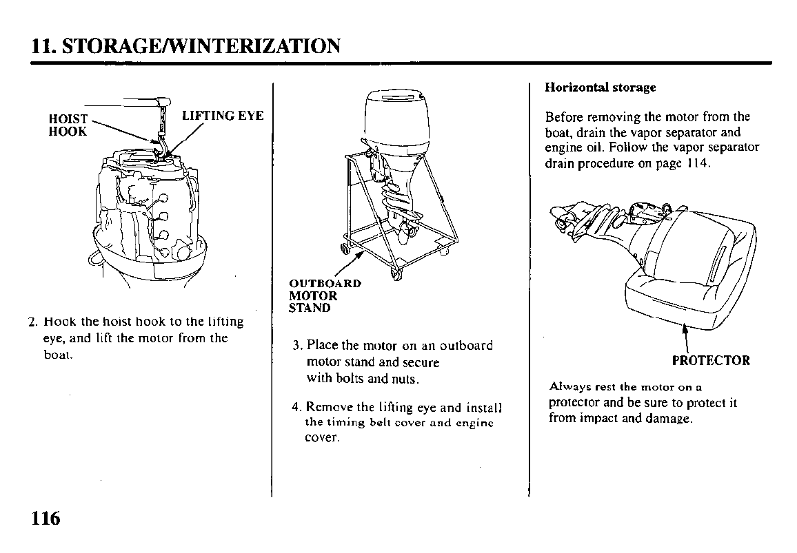
11. STORAGE/WINTERIZATION
EYE
2. Hook the hoist hook to the lifting
eye, and lift the motor from the
boat.
OUTBOARD
MOTOR
STAND
3. Place the motor on an outboard
motor stand and secure
with bolts and nuts.
4. Remove the lifting eye and install
the timing belt cover and engine
cover.
Horizontal storage
Before removing the motor from the
boat, drain the vapor separator and
engine oil. Follow the vapor separator
drain procedure on page 114.
PR’OTECTOR
Always rest the motor on a
protector and be sure to protect it
from impact and damage.
116
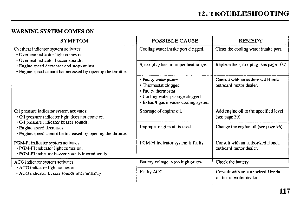
12. TROUBLESHOOTING
WARNING SYSTEM COMES ON
SYMPTOM
Overheat indicator system activates:
l
Overheat indicator light comes on.
l
Overheat indicator buzzer sounds.
l
Engine speed decreases and stops at last.
l
Engine speed cannot be increased by opening the throttle.
POSSIBLE CAUSE REMEDY
Cooling water intake port clogged. Clean the cooling water intake port.
Spark plug has improper heat range. Replace the spark plug (see page 102).
l
Faulty water pump Consult with an authorized Honda
l
Thermostat clogged outboard motor dealer.
l
Faulty thermostat
l
Cooling water passage clogged
l
Exhaust gas invades cooling system.
Oil pressure indicator system activates:
l
Oil pressure indicator light does not come on.
l
Oil pressure indicator buzzer sounds.
l
Engine speed decreases.
l
Engine speed cannot be increased by opening the throttle.
Shortage of engine oil.
Improper engine oil is used.
Add engine oil to the specified level
(see page 39).
Change the engine oil (see page 96).
PGM-FI indicator system activates:
l
PGM-FI indicator light comes on.
l
PGM-FI indicator buzzer sounds intermittently.
PGM-FI indicator system is faulty. Consult with an authorized Honda
outboard motor dealer.
ACG indicator system activates:
l
ACG indicator light comes on.
l
ACG indicator buzzer sounds intermittently.
Battery voltage is too high or low.
Faulty ACG
Check the battery.
Consult with an authorized Honda
outboard motor dealer.
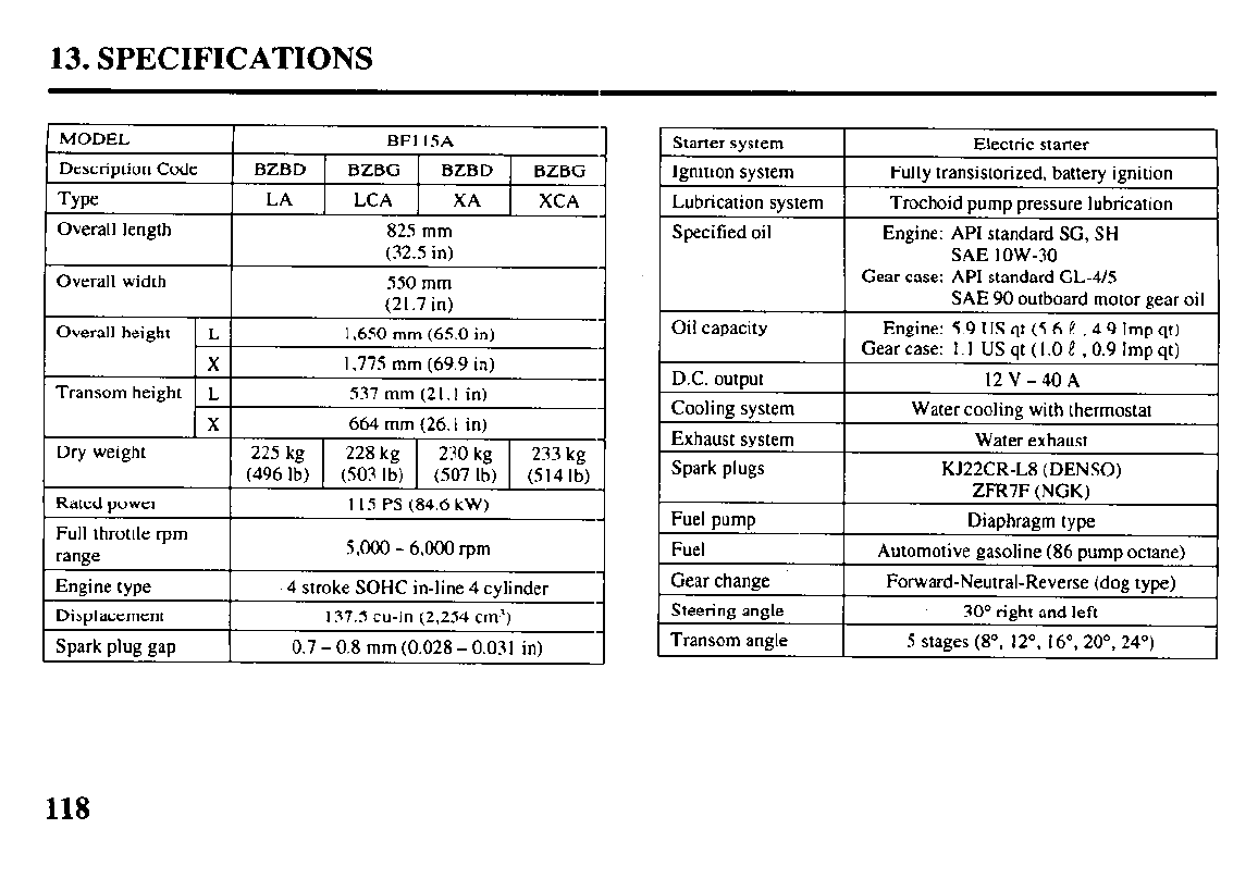
13. SPECIFICATIONS
Overall width I 550 mm 1
Overall height L
X
(21.7 in)
I.650 mm (65.0 in)
I.775 mm (69.9 in)
Full throttle rpm
range I S.000 - 6.000 ‘pm
Engine type 4 stroke SOHC in-line 4 cylinder
Displacement 137.5 cu-in (2.254 cm”)
Spark plug gap 0.7 - 0.8 mm (0.028 - 0.03 I in)
Starter system
Ignition system
Lubrication system
Specitied oil
Electric starter
Fully transistorized, battery ignition
Trochoid pump pressure lubrication
Engine: API standard SC, SH
SAE low-30
Oil capacity
D.C. output
Cooling system
Exhaust system
Spark plugs
Fuel pump
Fuel
Gear change
Steering angle
Transom angle
Gear case: API standard CL-4/S
SAE 90 outboard motor gear oil
Engine: 5.9 US qt (5.6 1 (4.9 Imp qt)
Gear case: I. I US qt (I .O f? ,0.9 imp qt)
12V-40A
Water cooling with thermostat
Water exhaust
KJ22CR-L8 (DENSO)
ZFR7F (NGK)
Diaphragm type
Automotive gasoline (86 pump octane)
Forward-Neutral-Reverse (dog type)
30” right and left
5 stages (8”, 12”. I6”, 20”. 24”)
118
ZFR7F (NGK); KJ22CR-L8 (DENSO)
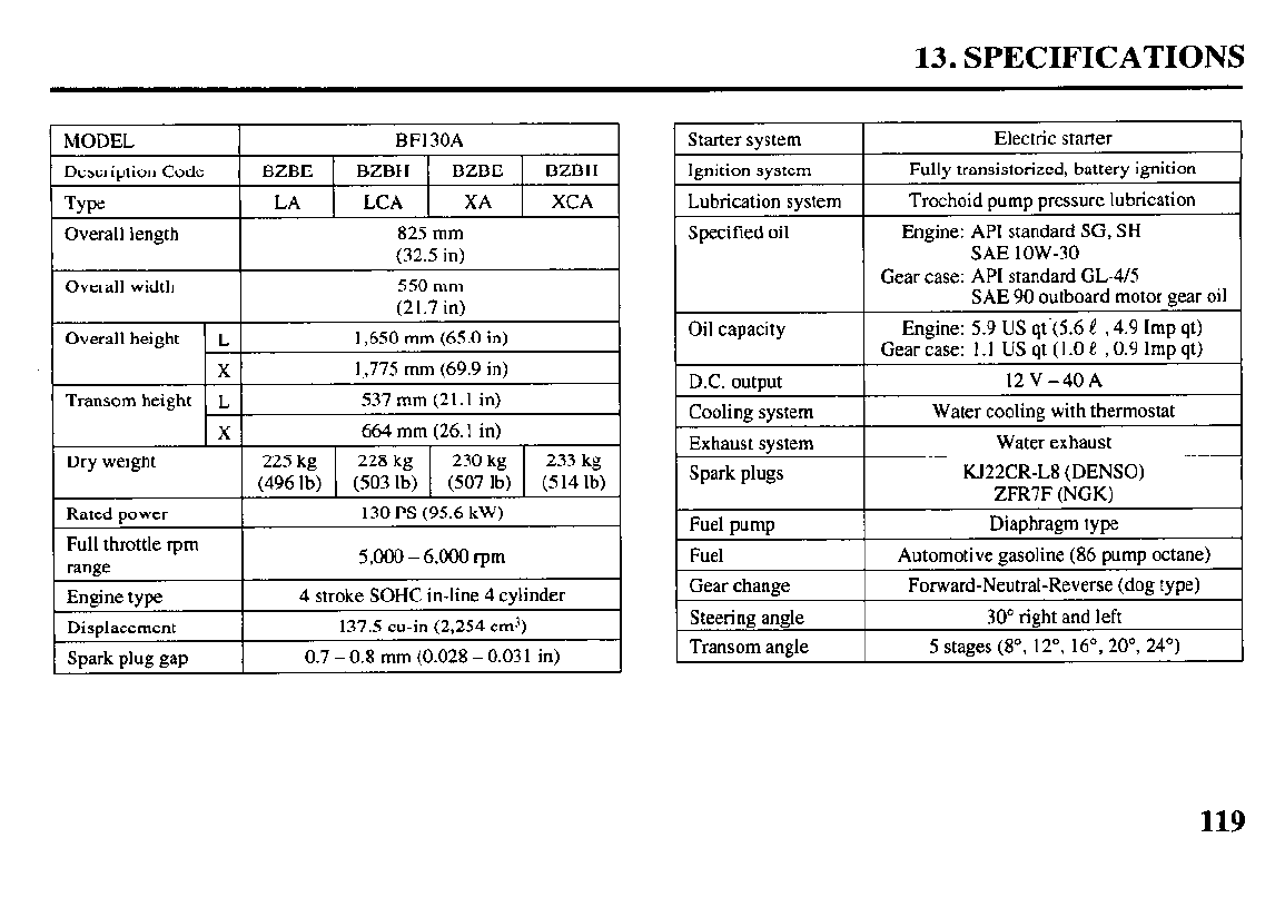
13. SPECIFICATIONS
MODEL I BFI 30A I
Descriotion Code 1 BZBE 1 BZBH 1 BZBE 1 BZBH 1
Overall height L 1,650 mm (65.0 in)
X I,,775 mm (69.9 in)
Transom height L 537 mm (21.1 in)
X 664 mm (26. I in)
Dry weight 225 kg 228 kg 230 kg 233 kg
(496 lb) (503 lb) (507 lb) (514 lb)
Rated Dower I 130 PS (95.6 kW) I
~1
4 stroke SOHC in-line 4 cylinder
Starter system
Ignition system
Lubrication system
Electric starter
Fully transistorized, battery ignition
Trochoid pump pressure lubrication
Engine: 5.9 US qt.(5.6 1 ,4.9 Imp qt)
Gear case: 1.1 US qt (I .O e (0.9 Imp qt)
D.C.
OUtDUt I
l2V-40A
Cooline svstem
I
Water coolina with thermostat
2
Automotive gasoline (86 pump octane)
Gear change Forward-Neutral-Reverse (dog type)
Steerine angle
I
30” right and left
Transom angle 5 stages (8”. 12”, 16’, 20”, 24”)
119
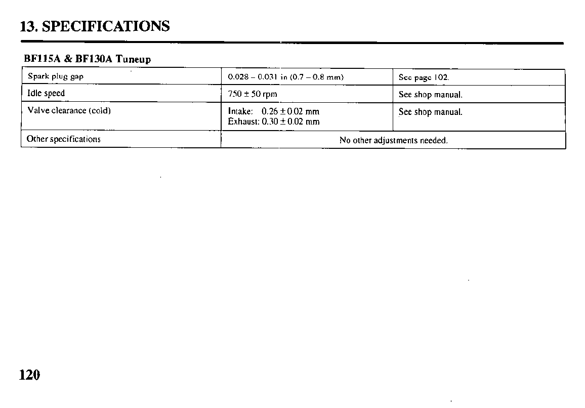
14. WARRANTY SERVICE
Warranty Service Information
Servicing dealership personnel are
trained professionals. They should be
able to answer any question you may
have. If you encounter a problem that
your dealer does not solve to your
satisfaction, please discuss it with the
dealership’s management. The Service
Manager or General Manager can help.
Almost all problems are solved in this
way.
If you are dissatisfied with the deci-
sion made by the dealership’s manage-
ment, contact the Honda Marine
Customer Relations Office. You can
write:
American Honda Motor Co., Inc.
Marine Division
Customer Relations Office
4900 Marconi Drive
Alpharetta, Georgia 300058847
Or telephone: (770) 497-6400
When you write or call, please give us
this information:
l
Model and serial numbers (see page
4)
l
Name of the dealer who sold the
outboard motor to you
l
Name and address of the dealer who
services your outboard motor
l
Date of purchase
l
Your name, address, and telephone
number
l
A detailed description of the problem
121
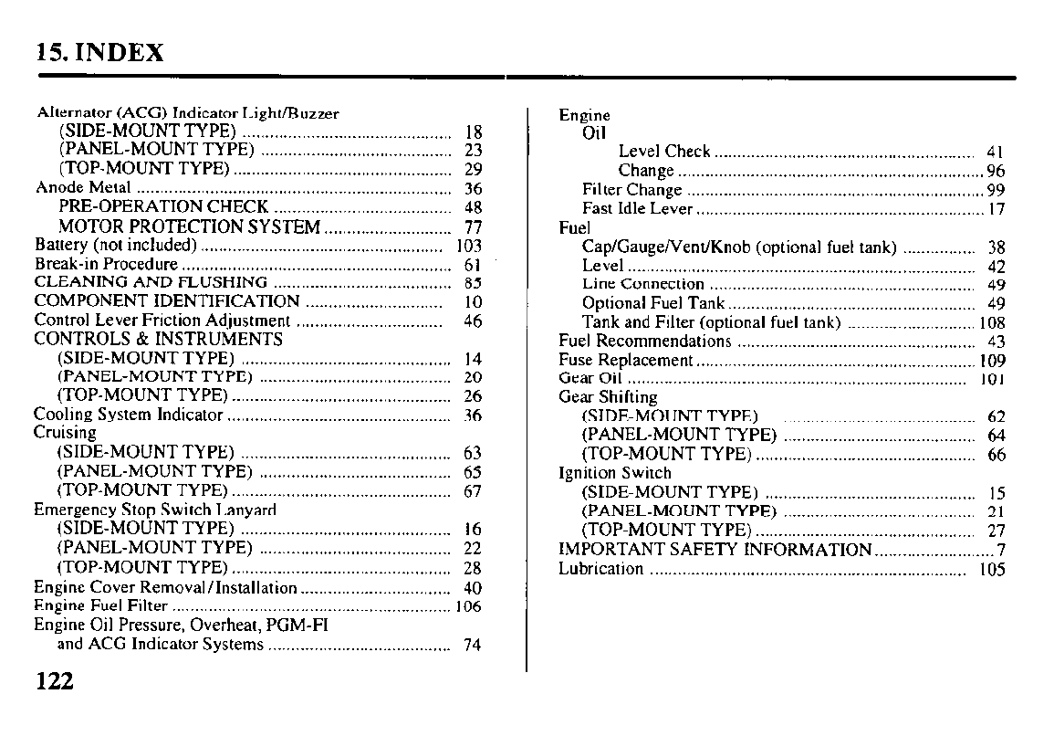
15. INDEX
Alternator (ACG) Indicator Light/Buzzer
(SIDE-MOUNT TYPE) .............................................. 18
(PANEL-MOUNT TYPE) .......................................... 23
(TOP-MOUNT TYPE) ................................................ 29
Anode Metal ..................................................................... 36
PRE-OPERATION CHECK ....................................... 48
MOTOR PROTECTION SYSTEM ............................ 77
Battery (not included) ..................................................... 103
Break-in Procedure ........................................................... 61
CLEANING AND FLUSHING ....................................... 85
COMPONENT IDENTIFICATION .............................. 10
Control Lever Friction Adjustment ................................ 46
CONTROLS & INSTRUMENTS
(SIDE-MOUNT TYPE) .............................................. 14
(PANEL-MOUNT TYPE) .......................................... 20
(TOP-MOUNT TYPE) ................................................ 26
Cooling System Indicator ................................................. 36
Cruising
(SIDE-MOUNT TYPE) .............................................. 63
(PANEL-MOUNT TYPE) .......................................... 65
(TOP-MOUNT TYPE) ................................................ 67
Emergency Stop Switch Lanyard
(SIDE-MOUNT TYPE) .............................................. 16
(PANEL-MOUNT TYPE) .......................................... 22
(TOP-MOUNT TYPE) ................................................ 28
Engine Cover Removal/Installation.. ............................... 40
Engine Fuel Filter ............................................................. 106
Engine Oil Pressure, Overheat, PGM-FI
and ACG Indicator Systems ........................................ 74
122
Engine
Oil Level Check.. ....................................................... 41
Change .................................................................. .96
Filter Change ................................................................ .99
Fast Idle Lever.. ............................................................. 17
Fuel
Cap/Gauge/Vent/Knob (optional fuel tank) ................ 38
Level ............................................................................ 42
Line Connection .......................................................... 49
Optional Fuel Tank.. .................................................... 49
Tank and Filter (optional fuel tank) ............................ 108
Fuel Recommendations .................................................... 43
Fuse Replacement.. ........................................................... IO9
Gear Oil .......................................................................... 101
Gear Shifting
(SIDE-MOUNT TYPE) .............................................. 62
(PANEL-MOUNT TYPE) .......................................... 64
(TOP-MOUNT TYPE) ................................................ 66
Ignition Switch
(SIDE-MOUNT TYPE) .............................................. I5
(PANEL-MOUNT TYPE) .......................................... 2 1
(TOP-MOUNT TYPE) ................................................ 27
IMPORTANT SAFETY INFORMATION.. ....................... .7
Lubrication ..................................................................... 105
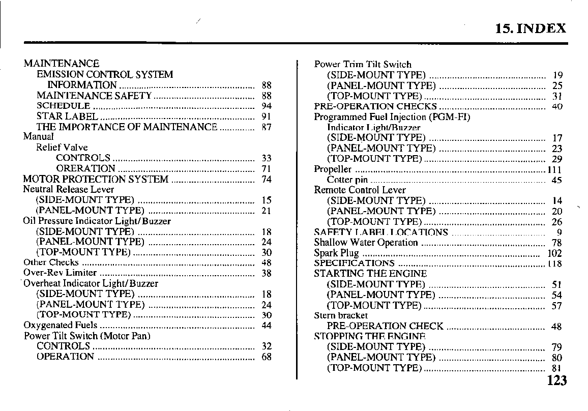
/
15. INDEX
MAINTENANCE
EMISSION CONTROL SYSTEM
INFORMATION ...................................................... 88
MAINTENANCE SAFETY.. ...................................... 88
SCHEDULE ................................................................ 94
STAR LABEL ............................................................. 91
THE IMPORTANCE OF MAINTENANCE .............. 87
Manual
Relief Valve
CONTROLS ........................................................ 33
ORERATION ...................................................... 7 1
MOTOR PROTECTION SYSTEM ................................. 74
Neutral Release Lever
(SIDE-MOUNT TYPE) .............................................. 15
(PANEL-MOUNT TYPE) .......................................... 21
Oil Pressure Indicator Light/Buzzer
(SIDE-MOUNT TYPE) .............................................. 18
(PANEL-MOUNT TYPE) .......................................... 24
(TOP-MOUNT TYPE) ................................................ 30
Other Checks .................................................................... 48
Over-Rev Limiter ............................................................. 38
‘Overheat Indicator Light/Buzzer
(SIDE-MOUNT TYPE) .............................................. 18
(PANEL-MOUNT TYPE) .......................................... 24
(TOP-MOUNT TYPE) ................................................ 30
Oxygenated Fuels ............................................................. 44
Power Tilt Switch (Motor Pan)
CONTROLS ................................................................ 32
OPERATION .............................................................. 68
Power Trim Tilt Switch
(SIDE-MOUNT TYPE) .............................................. 19
(PANEL-MOUNT TYPE) .......................................... 25
(TOP-MOUNT TYPE) ................................................ 3 1
PRE-OPERATION CHECKS .......................................... 40
Programmed Fuel Injection (PGM-FI)
Indicator Light/Buzzer
(SIDE-MOUNT TYPE) .............................................. 17
(PANEL-MOUNT TYPE) .......................................... 23
(TOP-MOUNT TYPE) ................................................ 29
Propeller ........................................................................... 111
Cotter pin ..................................................................... 45
Remote Control Lever
(SIDE-MOUNT TYPE) .............................................. 14
(PANEL-MOUNT TYPE) T .......................................... 20
(TOP-MOUNT TYPE) ................................................ 26
SAFETY LABEL LOCATIONS ..................................... 9
Shallow Water Operation ................................................. 78
Spark Plug ...................................................................... 102
SPECIFICATIONS .......................................................... 1 18
STARTING THE ENGINE
(SIDE-MOUNT TYPE) .............................................. 5 1
(PANEL-MOUNT TYPE) .......................................... 54
(TOP-MOUNT TYPE) ................................................ 57
Stern bracket
PRE-OPERATION CHECK ....................................... 48
STOPPING THE ENGINE
(SIDE-MOUNT TYPE) .............................................. 79
(PANEL-MOUNT TYPE) .......................................... 80
(TOP-MOUNT TYPE) ................................................ 8 1
123
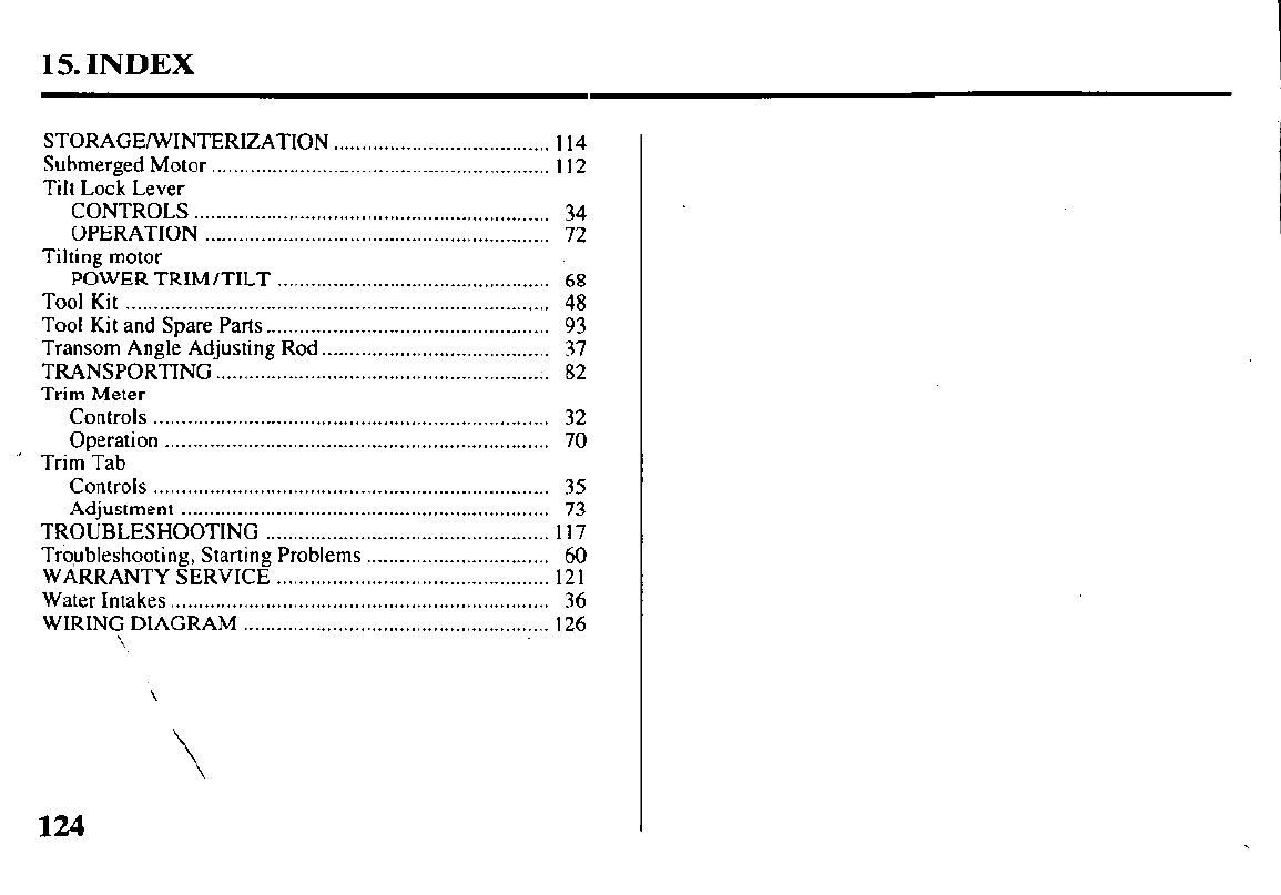
15. INDEX
STORAGE/WINTERIZATION ....................................... 1 14
Submerged Motor ............................................................. I 12
Tilt Lock Lever
CONTROLS ................................................................ 34
OPERATION .............................................................. 72
Tilting motor
POWER TRIM/TILT ................................................. 68
Tool Kit ............................................................................ 48
Tool Kit and Spare Parts.. ................................................. 93
Transom Angle Adjusting Rod.. ....................................... 37
TRANSPORTING ............................................................ 82
Trim Meter
Controls ....................................................................... 32
Operation ..................................................................... 70
’ Trim Tab
Controls ....................................................................... 35
Adjustment .................................................................. 73
TROUBLESHOOTING ................................................... I 17
Troubleshooting, Starting Problems ................................. 60
WARRANTY SERVICE ................................................. 12 1
Water Intakes .................................................................... 36
WIRING DIAGRAM ....................................................... 126
\
\
124
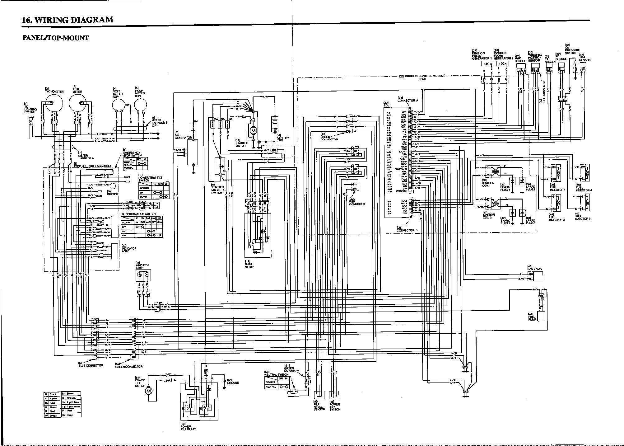
16. WIRING DIAGRAM
PANEL/FOP-MOUNT
r-.-. .-..-
1
-
-
I---- ___.. -..-..-.
___-..-..
1
I
i
-
-
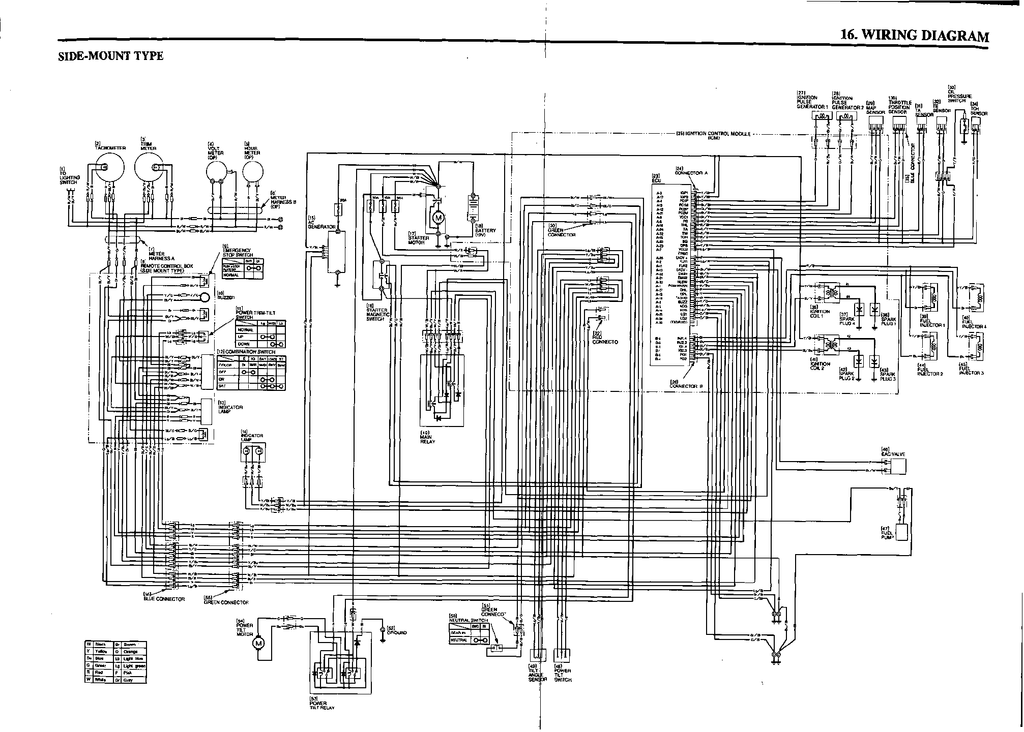
-
-
-
-


31ZW5602
