Honda Bf50 5Hp Bf50S 1000001 9999999 Owners Manual
31ZV1010 Honda Marine – 4-Stroke Outboard Motors, Parts, Accessories, Financing | Official Site
2014-11-13
: Honda Honda-Bf50-5Hp-Bf50S-1000001-9999999-Owners-Manual-107981 honda-bf50-5hp-bf50s-1000001-9999999-owners-manual-107981 honda pdf
Open the PDF directly: View PDF ![]() .
.
Page Count: 49


Thank you for purchasing a Honda Outboard Motor.
This manual covers operation and maintenance of the Honda Outboard
Motor. All information in this publication is based on the latest product
information available at the time of approval for printing.
Honda Motor Co., Ltd. reserves the right to make changes at any time without
notice and without incurring any obligation.
No part of this publication may be reproduced without written permission.
This manual should be considered a permanent part of the Outboard Motor
and should remain with the Outboard Motor when it is sold.
Pay special attention to statements preceded by the following words:
B Indicates a strong possibility of severe personal injury or loss of
life if instructions are not followed.
CAUTION: Indicates a possibility of personal injury or equipment damage if
instructions are not followed.
NOTE: Gives helpful information.
If a problem should arise, or if you have any questions about the Outboard
Motor, consult an authorized Honda dealer.
w Honda Outboard Motors are designed to give safe and dependable
service if, operated according to instructions. Read and understand the
Owner’s Manual before operating the Outboard Motor. Failure to do so could
result in personal injury or equipment damage
1
CONTENTS
1. SAFETY INSTRUCTIONS ............................. i.. ........................... 3
2. WARNING LABELS ................................................................... 4
3. COMPONENT IDENTIFICATION .................................................. 6
4. INSTALLATION ....................................................................... 8
5. PRE-OPERATION CHECK ........................................................... 10
6. STARTING THE ENGINE ............................................................ 13
7. OPERATION ............................................................................ 18
8. STOPPING THE ENGINE ............................................................ 24
l
High altitude operation.. ...................................................... 24
9. MAINTENANCE ....................................................................... 25,
10. TRANSPORTING/STORAGE ....................................................... 36
11. TROUBLESHOOTING ..................... i ........................................... 38
12. SPECIFICATIONS ..................................................................... 39
13. WIRING DIAGRAM ................................................................... 40
14. OPTIONAL PARTS .................................................................... 41
15. WARRANTY SERVICE ............................................................... 42
2
1. SAFETY INSTRUCTIONS
To ensure safe operation-
0 Understand the operation of all controls, and know how to stop the
engine quickly -READ THIS OWNER’S MANUAL CAREFULLY.
0 Do not exceed the boat manufacturer’s power recommendation, and be
sure the outboard motor is properly mounted.
0 Never permit anyone to operate the outboard motor without proper
instruction.
0 Stop the engine immediately if any passenger falls overboard.
0 Do not run the motor while the boat is near any person in the water.
0 Exhaust gas contains poisonous carbon monoxide. Never run the out-
board motor in a closed garage or confined area.
0 Gasoline is extremely flammable and is explosive under certain condi-
tions. Refuel in a well ventilated area with the engine stopped.
0 Do not smoke or allow flames or sparks where the engine is refueled or
where gasoline is stored.
0 Do not overfill the fuel tank, and make sure the fuel tank cap is securely
closed after refueling.
0 Be careful not to spill fuel when refueling. Fuel vapor or spilled fuel may
ignite. If any fuel is spilled, make sure the area is dry before starting the
engine. ,
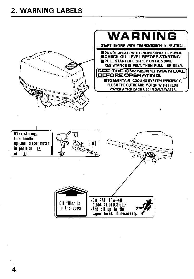
2. WARNING LABELS
[ WARNING
START ENGINE WlTH TRANSMISSION IN NEUTRAL.
MD0 NOT OPEATE WITH ENGINE COVER REMOVED.
n
CHECK OIL LEVEL BEFORE STARTING.
n
PULL STARTER LIGHTLY UNTIL SOME
RESISTANCE IS FELT.THEN PULL BRISKLY.
SEE THE OWNER’S MANUAL’
BEFORE OPERATING.
WTO MAINTAIN COOLING SYSTEM EFFICIENCY,
FLUSH THE OUTBOARD MOTOR WITH FRESH
L WATER AFTER EACH USE IN SALT WATER.
When storing,
turn handle
up and place .motor
iC position
q
or 0. I
4
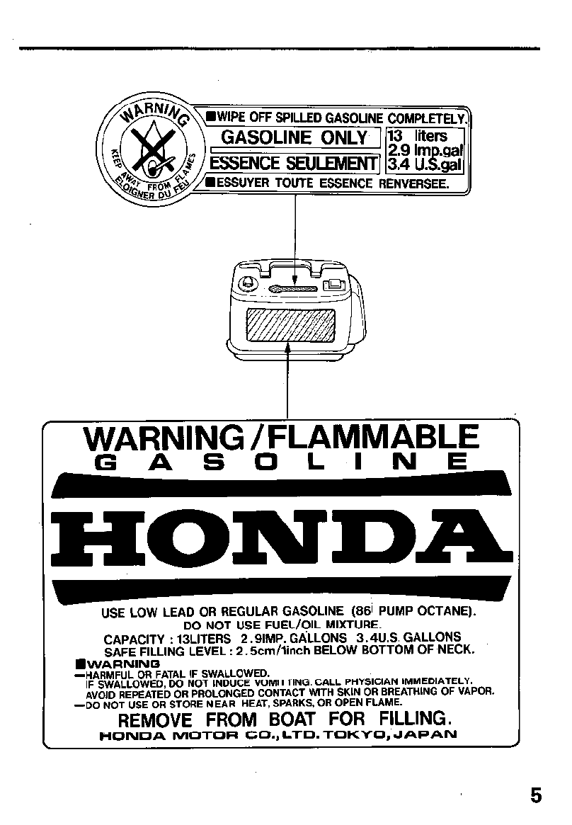
WARNING /F’LAMMABLE
GASOLINE_
HONDA
USE LOW LEAD OR REGULAR GASOLINE (88i PUMP OCTANE).
DO NOT USE FUEL/OIL MIXTURE.
CAPACITY : 13LITERS 2.9lMP. GALLONS 3.4U.S. GALLONS
SAFE FILLING LEVEL : 2.5cm/linch BELOW BOTTOM OF NECK.
WVARNING
-HARMFUL OR FATAL IF SWALLOWED.
IF SWALLOWED, DO NOT INDUCE VOMITTING. CALL PHYSICIAN IMMEDIATELY.
AVOID REPEATED OR PROLONGED CONTACT WITH SKIN OR BREATHING OF VAPOR.
-DO NOT USE OR STORE NEAR HEAT, SPARKS, OR OPEN FLAME.
REMOVE FROM BOAT FOR FILLING.
HONDA MOTOR CO., LTD. TOKYO, JAPAN
5
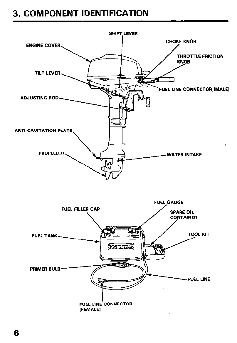
3. COMPONENT IDENTlFlCATlON
SHIFT,LEVER
CHOKE KNOB
ENGINE COVER
THROlTLE FRICTION
B
FUEL LINE CONNECTOR, (MALE)
ADJUSTING ROD
ANTI-CAVITATION PLATE
\
’
pRopELLER*yiWA~~~ INTAKE
FUEL,GAUGE
FUEL F
FUEL TANK
PRIMER BULB
. KIT
LINE
I
FUEL LINE CONNECTOR
(FEMALE)
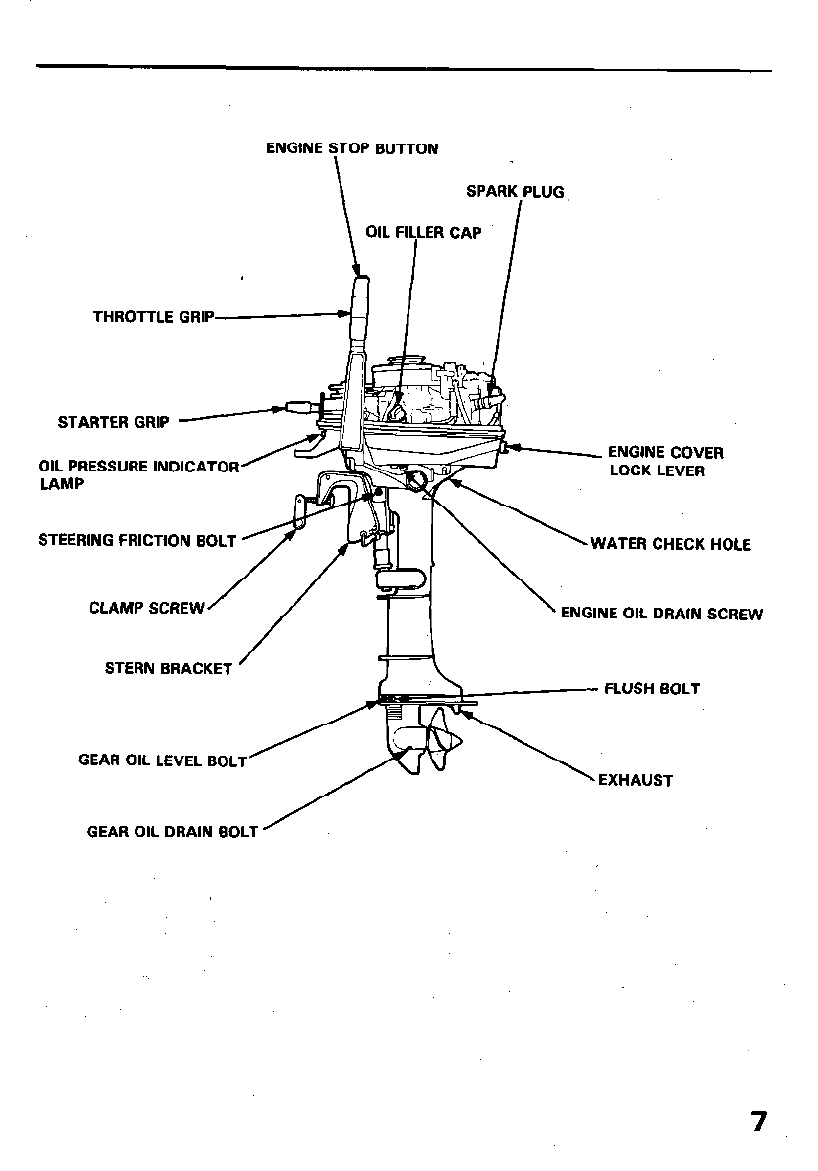
ENGINE STOP BUTTON
\
SPARK PLUG
OIL FILLER CAP
I I
THROTTLE GRIP-4 1 /
STARTER GRIP
OIL PRESSURE INDICATOR
LAMP
ENGINE COVER
STERN BRACKET FLUSH BOLT
GEAR OIL LEVEL BOLT EXHAUST
GEAR OIL DRAIN BOLT ’
7

4. INSTALLATION
It is your responsibility to choose
a boat suitable for the engine (5
horsepower).
manufacturer’s power recommen-
dation. Damage and injury may
result.
1. Installation Position
Install at the stern at the center line
of the boat.
2. Installation Height
Make sure that the transom height
is correct for the motor. Incorrect
installation height will reduce per-
formance.
The motor should be installed so
that the anti-cavitation plate is
2-5 cm (0.8-2.0 in) below the
bottom of the boat.
CAUTION: The water level must
be at least 4 inches above the anti-
cavitation plate, otherwise the
water pump may not receive suffi-
cient cooling water, and the exten-
sion case will overheat.
3. Motor Attachment
Attach the stern bracket to the
transom and tighten the clamp
, screws.
CAUTION:
0 While operating the boat, check
the tightness of the clamp
screws occasionally.
0 Tie a rope through the hole in the
stern bracket and secure the
other end of the rope to the
boat. This will prevent acciden-
tal loss of the motor.
TRANSOMrHElGHT
5ss+f+
fi
STERN CENTER
2-5 cm
-.
t
(0.8-2.0
SAFETY\ ROPE
8.
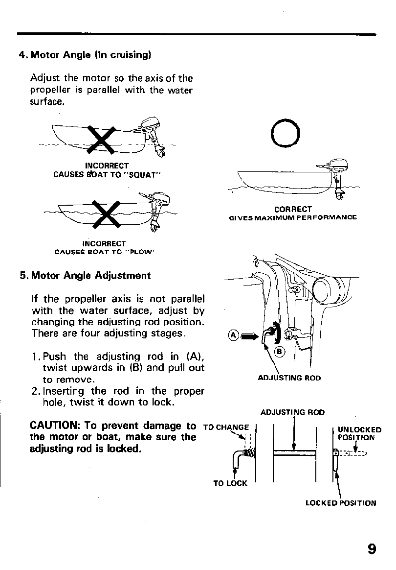
4. Motor Angle (In cruising)
Adjust the motor so the axis of the
propeller is parallel with the water
surface.
INCORRECT
CAUSES BOAT TO “SQUAT-
CORRECT
GIVES MAXIMUM PERFORMANCE
INCORRECT
CAUSES BOAT TO “PLOW’
5. Motor Angle Adjustment
If the propeller axis is not parallel
with the water surface, adjust bv
changing the adjusting rod position.
There are four adjusting stages.
1. Push the adjusting rod in (A),
twist upwards in (B) and pull out
to remove.
2. Inserting the rod in the proper
hole, twist it down to lock.
ADJUSTING ROD
ADJUSTING ROD
CAUTION: To prevent damage to TO ““~7
the motor or boat, make sure the
adjusting rod is locked.
LOCKED POSITION
9

5. PRE-OPERATION CHECK
1. Check the engine oil level.
CAUTION:
l
Engine oil is a major factor affecting engine performance and service life.
Non-detergent and low quality oils are not recommended.
l
Running the engine with insufficient oil can cause serious engine damage.
Use Honda 4-stroke oil, or an
equivalent high detergent, premium
quality motor oil certified to meet or
exceed U.S. automobile manufac-
turer’s requirements for Service
Classification SE or SF. (Motor oils
classified SE or SF will show this
designation on the container.)
Select the appropriate viscosity for
the average temperature in your
area.
-20 0 20 40 60 60 lO(PF
-30 -2b -10 0 10 20 30 40°C
1. Position the outboard motor vertically; and remove the engine cover.
2. Remove the dipstick and wipe with a clean rag.
3. Reinsert the dipstick, and check the oil level with the dipstick resting on
the filler opening (do not screw in). If the oil level is low, fill to the
upper level mark.
Oil capacity: 0.55 P (0.58 US qt)
DIPSTICK
ENGCNE COVER LOCK LEVER
UNLOCK UPPER LEVEL (0.55 t’),
LOWER LEVEL 10.40 e)
10

2. Check the fuel level
Check the fuel gauge and refill the tank if the fuel level is low.
NOTE: Open the vent knob before removing the fuel filler cap. When the
vent knob is firmly closed, the cap will be difficult to remove.
Use any regular grade automotive gasoline (unleaded gasoline is preferred)
with a pump octane rating of 86 or higher. Never use an oil/gasoline
mixture or dirty gasoline. Avoid getting dirt, dust or water in the fuel tank.
CAUTION: Gasoline substitutes are not recommended; they may be
harmful to the fuel system components.
Fuel tank capacity: 13 e (3.4 US gal)
l
Gasoline is extremely flammable and is explosive under certain
conditions.
l
Do not smoke or allow flames or sparks near the fuel tank and fuel line.
l
Do not overfill the tank and make sure the filler cap is securely closed
after refueling.
l
Be careful not to spill fuel when refueling. Fuel vapor or spilled fuel
may ignite. lf any fuel is spilled, make sure the area is dry before starting
the engine.
FUEL-GAUGE VENT KNOB
-- FUEL FILLER 6AP
I
11
3. Check the following items.
0 Check the propeller, the shear pin, and the cotter pin to be sure they
are secure and undamaged.
0 Check the stern bracket to be sure the motor is securely installed.
0 Check steering handle operation.
0 Make sure you have the tool kit and spare parts with you (p. 26).
12
6. STARTING THE ENGINE
CAUTION: Damage to the water pump, engine components and exhaust
system may occur if the motor is operated while the propeller is out the
water.
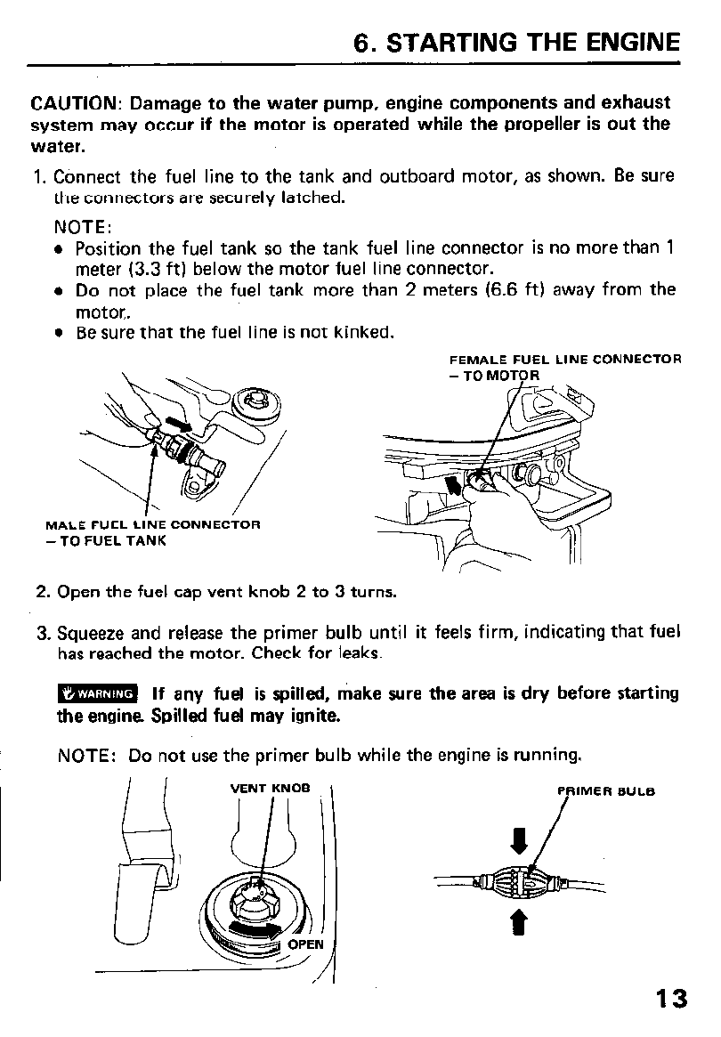
1. Connect the fuel line to the tank and outboard motor, as shown. Be sure
the connectors are securely latched.
NOTE:
l
Position the fuel tank so the tank fuel line connector is no more than 1
meter (3.3 ft) below the motor fuel line connector.
l
Do not place the fuel tank more than 2 meters (6.6 ft) away from the
motor..
l
Be sure that the fuel line is not kinked.
FEMALE FUEL LINE CONNECTOR
MALE FUEL LINE CONNECTOR
-TO FUEL TANK
2. Open the fuel cap vent knob 2 to 3 turns.
3. Squeeze and release the primer bulb until it feels firm, indicating that fuel
has reached the motor. Check for leaks.
N If any fuel is spilled, make sure the area is dry before starting
the engine. Spilled fuel may ignite.
NOTE: Do not use the primer bulb while the engine is running.
PRIMER BULB
/
13
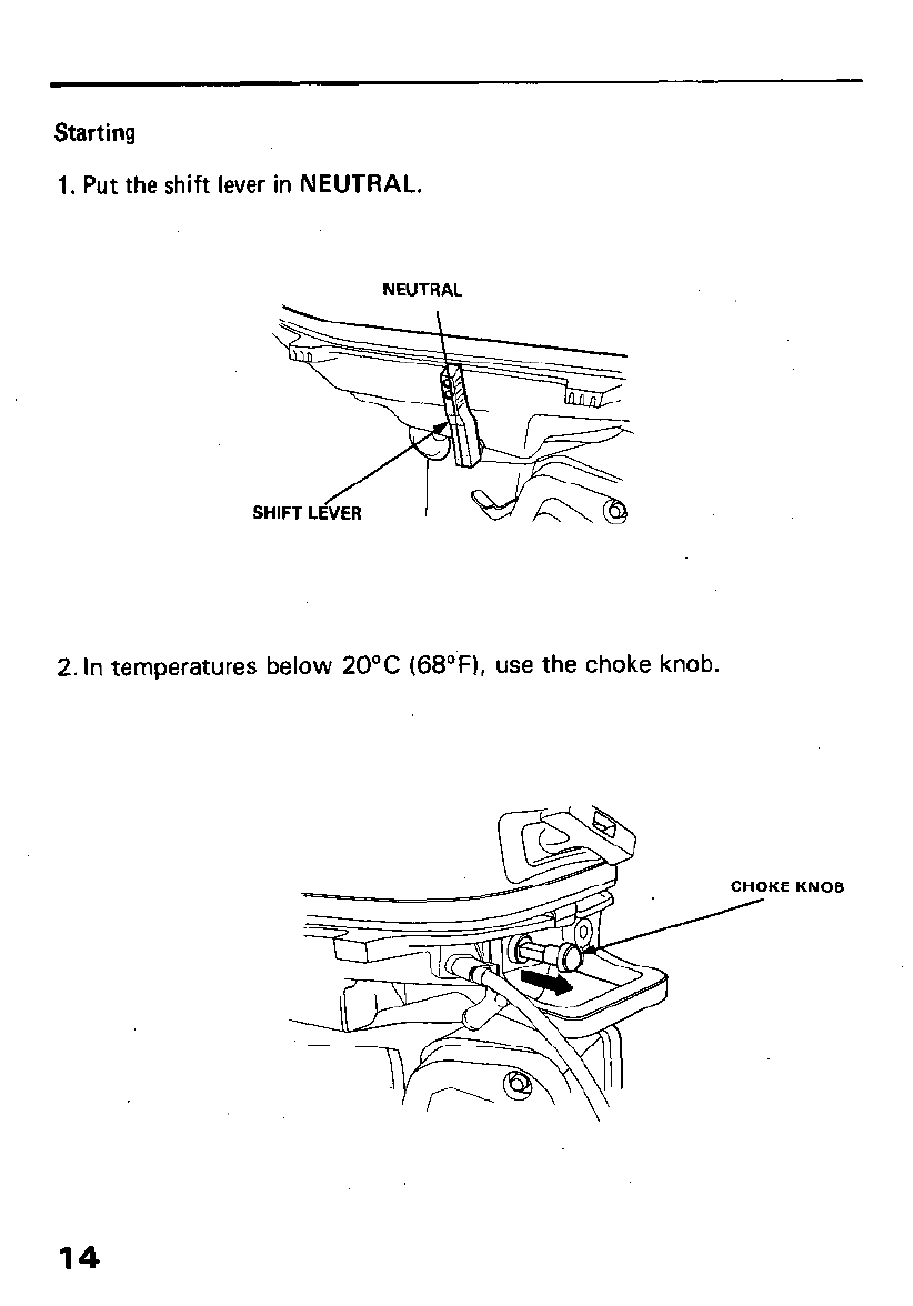
Starting
1. Put the shift lever in NEUTRAL.
NEUTRAL
2. In temperatures below 20°C (68OF), use the choke knob.
KE KNOB
14
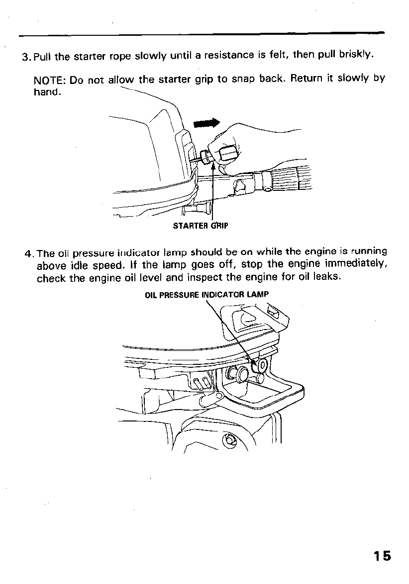
3. Pull the starter rope slowly until a resistance is felt, then pull briskly.
NOTE: Do not allow the starter grip to snap back. Return it slowly by
hand.
STARTER GRIP
4. The oil pressure indicator lamp should be on while the engine is running
above idle speed. If the lamp goes off, stop the engine immediately,
check the engine oil level and inspect the engine for oil leaks.
OIL PRESSURE INDICATOR LAMP
15

5. After starting, be! sure water is flowing out of the water check hole.
CAUTION: If water does not flow out, or if steam comes out, stop CAUTION: If water does not flow out, or if steam comes out, stop
engine. Check to see if the water intake holes are obstructed. Do engine. Check to see if the water intake holes are obstructed. Do
operate the engine until the problem has been corrected. operate the engine until the problem has been corrected.
X
0
WATER CilECK- HOLE
the
not
6. If the choke was used, push it in gradually as the engine warms up.
16
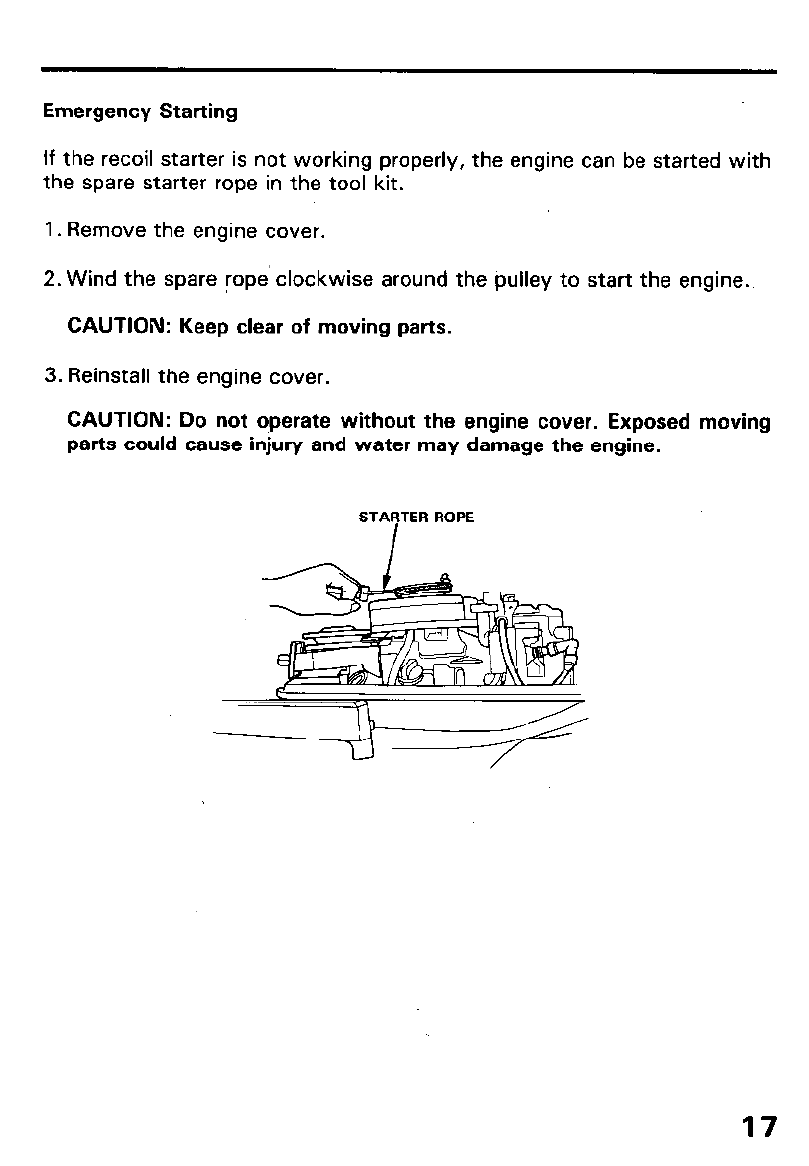
Emergency Starting
If the recoil starter is not working properly, the engine can be started with
the spare starter rope in the tool kit.
1. Remove the engine cover.
2. Wind the spare rope’clockwise around the pulley to start the engine.
CAUTION: Keep clear of moving parts.
3. Reinstall the engine cover.
CAUTION: Do not operate without the engine cover. Exposed moving
parts could cause injury and water may damage the engine.
STARTER ROPE
7. OPERATION
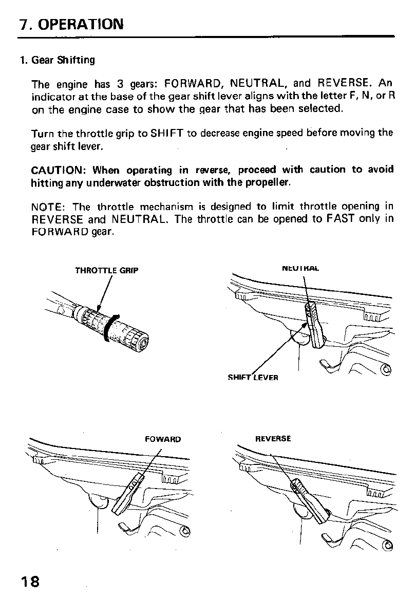
1. Gear Shifting
The engine has 3 gears: FORWARD, NEUTRAL, and REVERSE. An
indicator at the base of the gear shift lever aligns with the letter F, N, or R
on the engine case to show the gear that has been selected.
Turn the throttle grip to SHIFT to decrease engine speed before moving the
gear shift lever.
CAUTION: When operating in reverse, proceed with caution to avoid
hitting any underwater obstruction with the propeller.
NOTE: The throttle mechanism is designed to limit throttle opening in
REVERSE and NEUTRAL. The throttle can be opened to FAST only in
FORWARD gear.
NEUTRAL
REVERSE
18

2. Steering
To turn to the right, swing the steering handle to the left. To turn to the
left, swing the handle to the right.
For smooth steering, adjust the steering friction bolt so that a slight drag
is felt when turning.
STEERING FRICTION BOLT
I
\ \ \ \
T& INLREASE
FRlCTltlN
19
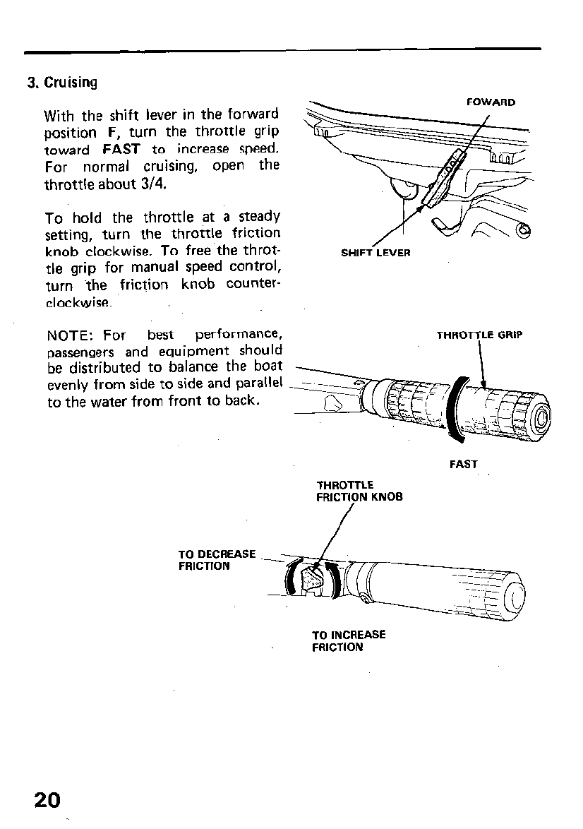
3. Cruising
With the shift lever in the forward
position F, turn the throttle grip
toward FAST to increase speed.
For normal cruising, open the
throttle about 3/4.
To hold the throttle at a steady
setting, turn the throttle friction
knob clockwise. To free.the throt-
tle grip for manual speed control,
turn the friction knob counter-
clockwise.
SHIFT LEVER
NOTE: For best performance,
passengers and equipment should
be distributed to balance the boat
evenly from side to side and parallel
to the water from front to back.
THROTTLE GRIP
FAST
THROTTLE
FRICTION KNOB
TO DECREASE
FRICTION
TO INCREASE
FRICTION
20
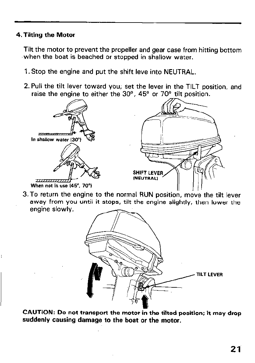
4. Tilting the Motor
Tilt the motor to prevent the propeller and gear case from hitting bottom
-when the boat is beached or stopped in shallow water.
1. Stop the engine and put the shift leve into NEUTRAL.
2. Pull the tilt lever toward you; set the lever in the TILT position,
raise the engine to either the 30’. 45’ or 70’ tilt oosition. and
In
3.To return the engine to the normal RUN position, mdv’e the tilt lever
away from you until it stops, tilt the engine slightly, then lower the
engine slowly.
TILT LEVER
CAUTION: Do not transport the motor in the tilted position; it may drop
suddenly causing damage to the boat or the motor.
21
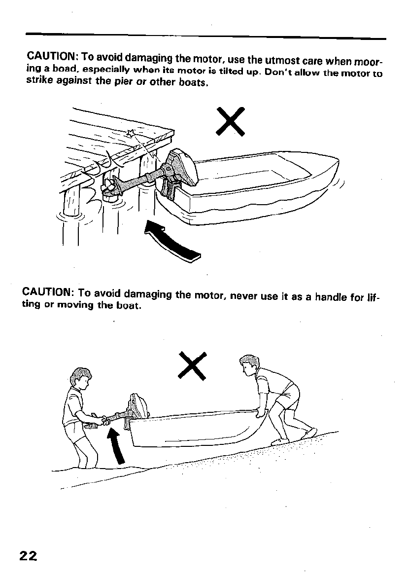
CAUTION: To avoid damaging the motor, use the utmost care when
moor-
ing a boad, especially when its motor is tilted up. Don’t allow the motor to
strike against the pier or other boats.
CAUTION: To avoid damaging the motor, never use it as a handle for lif-
ting or moving the boat.
22

5. Battey Charging and Lighting (Optional parts)
The DC receptacle provides a 12V, 40W current for 12V battery charg-
ing and lighting. The circuit is protected by a 5A fuse that is accessible
by removing the engine cover.
An electrical plug for the DC receptacle is supplied with your motor. Wire
your charging or lighting cord to this plug.
w Batteries produce explosive gases. Keep sparks, flames, and
cigarettes away. To prevent the possibility of creating a spark near the
battery, connect the charging cords first to the battery, then to the
outboard motor, and disconnect the charging cords first at the outboard
motor.
CAUTION:
l
Connect the positive battery terminal to the positive charging cord. DD
not reverse the charging cords, or serious damage to the outboard
motor’s charging circuit and/or battery may occur.
l
When not in use, cover the DC receptacle with the rubber cover to keep
it dry and clean.
DC RECEPTACLE
\ FUSE HOLDER
FUSE‘ (5A)
RUBBER’COVER
23
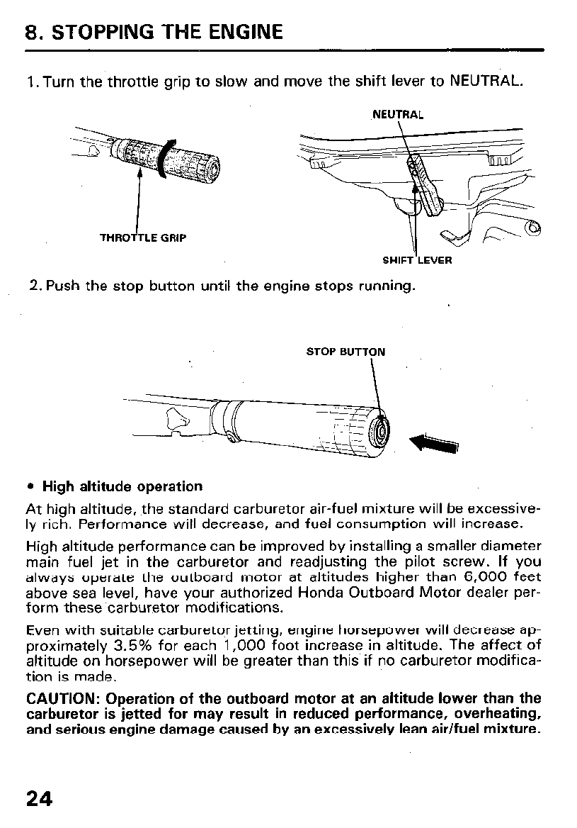
8. STOPPING THE ENGINE
1 .Turn the throttle grip to slow and move the shift lever to NEUTRAL.
NEUTRAL
SHIFT LEVER
2. Push the stop button until the engine stops running.
STOP BUTTON
I
l
High altitude operation
At high altitude, the standard carburetor air-fuel mixture will be excessive-
ly rich. Performance will decrease, and fuel consumption will increase.
High altitude performance can be improved by installing a smaller diameter
main fuel jet in the carburetor and readjusting the pilot screw. If you
always operate the outboard motor at altitudes higher than 6,000 feet
above sea level, have your authorized Honda Outboard Motor dealer per-
form these ‘carburetor modifications.
Even with suitable carburetor jetting, engine horsepower will decrease ap-
proximately 3.5% for each 1,000 foot increase in altitude. The affect of
altitude on horsepower will be greater than this if no carburetor modifica-
tion is made.
CAUTION: Operation of the outboard motor at an altitude lower than the
carburetor is jetted for may result in reduced performance, overheating,
and serious engine damage caused by an excessively lean air/fuel mixture.
24
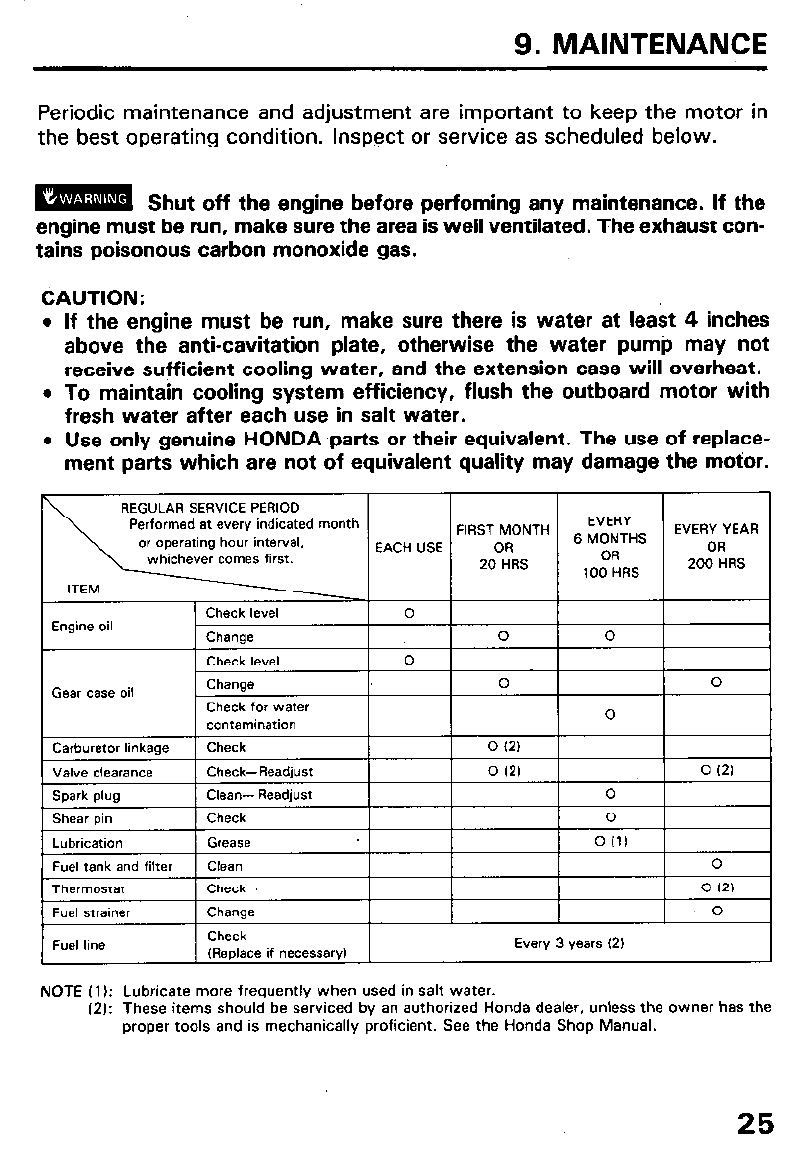
9. MAINTENANCE
Periodic maintenance and adjustment are important to keep the motor in
the best operating condition. Inspect or service as scheduled below.
m Shut off the engine before perfoming any maintenance. If the
engine must be run, make sure the area is well ventilated. The exhaust con-
tains poisonous carbon monoxide gas.
CAUTION:
l
If the engine must be run, make sure there is water at lea& 4 inches
above the anti-cavitation plate, otherwise the water pump may not
receive sufficient cooling water, and the extension case will overheat.
l
To maintain cooling system efficiency, flush the outboard motor with
fresh water after each use in salt water.
l
Use only genuine HONDA parts or their equivalent. The use of replace-
ment parts which are not of equivalent quality may damage the motor.
REGULAR SERVICE PERIOD
Performed at every indicated month
or operating hour interval,
whichever comas first.
FIRST MONTH EVERY YEAR
Gear case oil
Shear pin Check 0
Lubrication Grease 0 (1)
Fuel tank and filter Clean 0
Thermostat Check 0 (21
Fuel strainer Change 0
Fuel line Check
(Replace if necessary) Every 3 years (2)
NOTE (1): Lubricate more frequently when
used in salt water.
(2): These items should be serviced by an authorized Honda dealer, unless the owner has the
proper tools and is mechanically proficient. See the Honda Shop Manual.
25
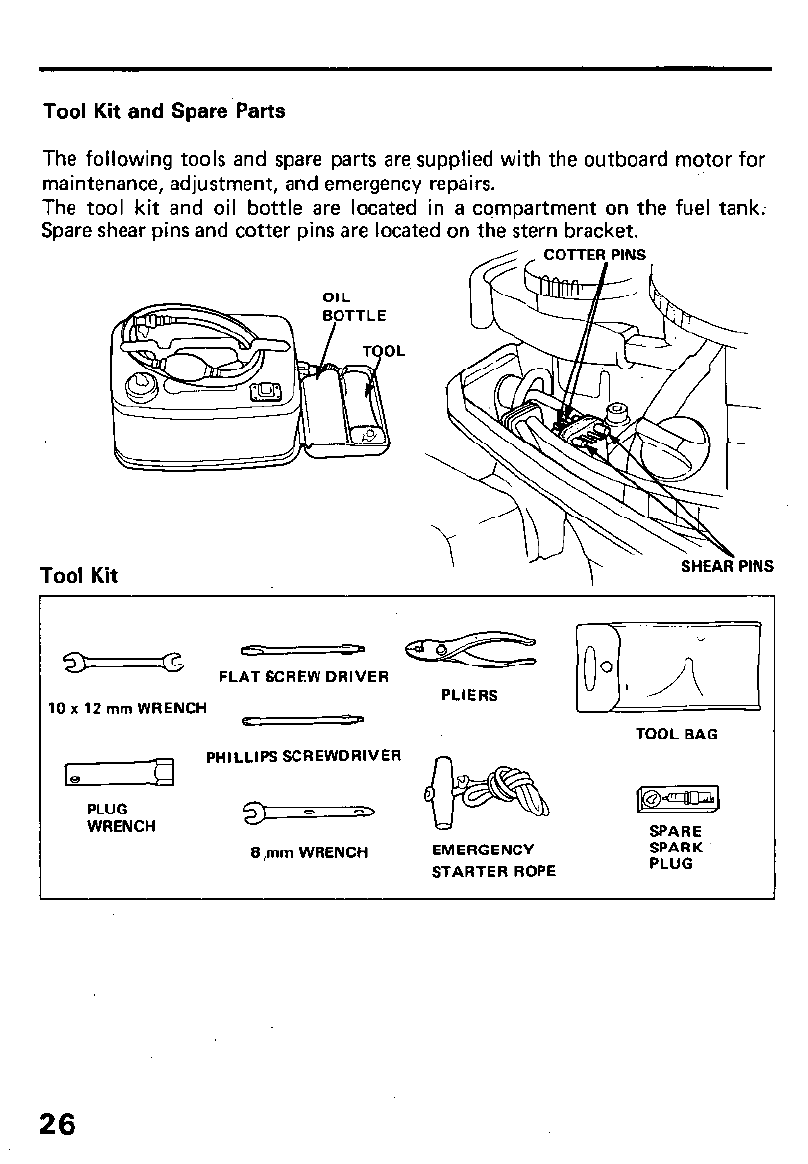
Tool Kit and Spare Parts
The following tools and spare parts are supplied with the outboard motor for
maintenance, adjustment, and emergency repairs.
The tool kit and oil bottle are located in a compartment on the fuel tank:
Spare shear pins and cotter pins are located on the stern bracket.
_ COTTER PINS
Tool Kit
>w
SHEAR PINS
G FLAT SCREW DRIVER
10 x 12 mm WRENCH
PHILLIPS SCREWDRIVER
PLIERS
TOOL BAG
PLUG
WRENCH GJ 0 o‘,
8 ,mm WRENCH EMERGENCY
STARTER ROPE
SPARE
SPARK
PLUG
26
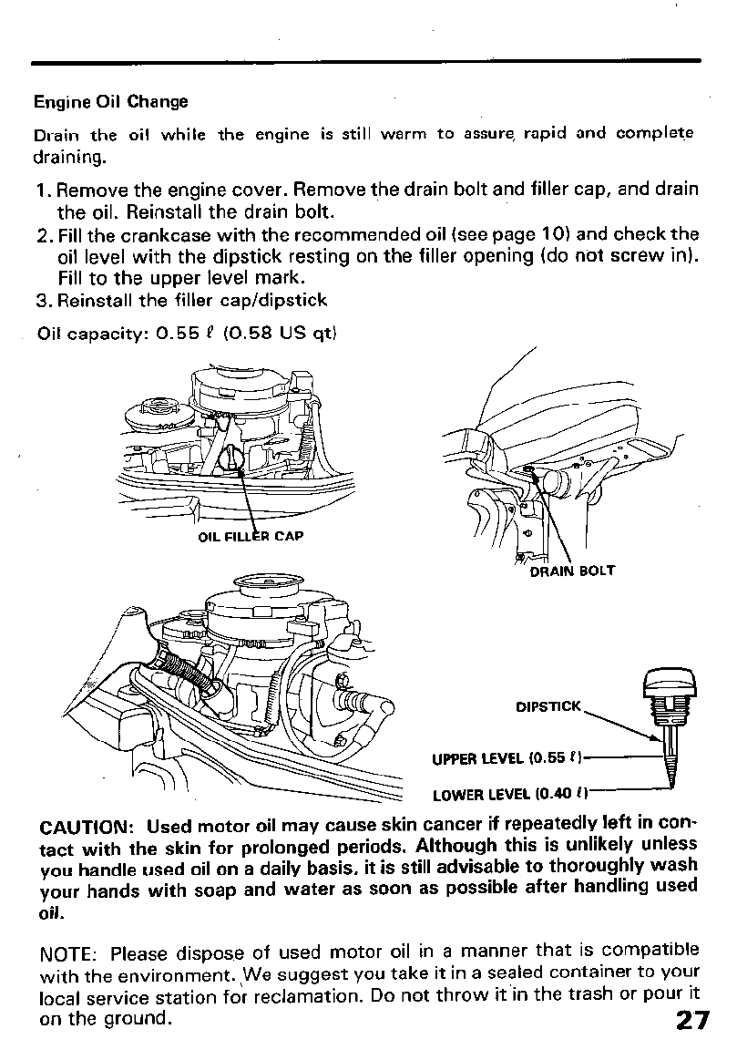
Engine Oil Change
Drain the oil while the engine is still warm to assure, rapid and complete
draining.
1. Remove the engine cover. Remove the drain bolt and filler cap, and drain
the oil. Reinstall the drain bolt.
2. Fill the crankcase with the recommended oil (see page 10) and check the
oil level with the dipstick resting on the filler opening (do not screw in).
Fill to the upper level mark.
3. Reinstall the filler cap/dipstick
Oil capacity: 0.55 P (0.58 US qt)
OIL FILLkR CAP
DRAIN BOLT
DIPSTICK
UPPER LEVEL IO.55 PI
LOWER LEVEL (0.40 0)
CAUTION: Used motor oil may cause skin cancer if repeatedly left in con-
tact with the skin for prolonged periods. Although this is unlikely unless
you handle used oil on a daily basis, it is still advisable to thoroughly wash
your hands with soap and water as soon as possible after handling used
oil.
NOTE: Please disp0s.e of used motor oil in a manner that is compatible
with the environment. !We suggest you take it in a sealed container to your
local service station for reclamation. Do not throw it’in the trash or pour it
on the ground.
27
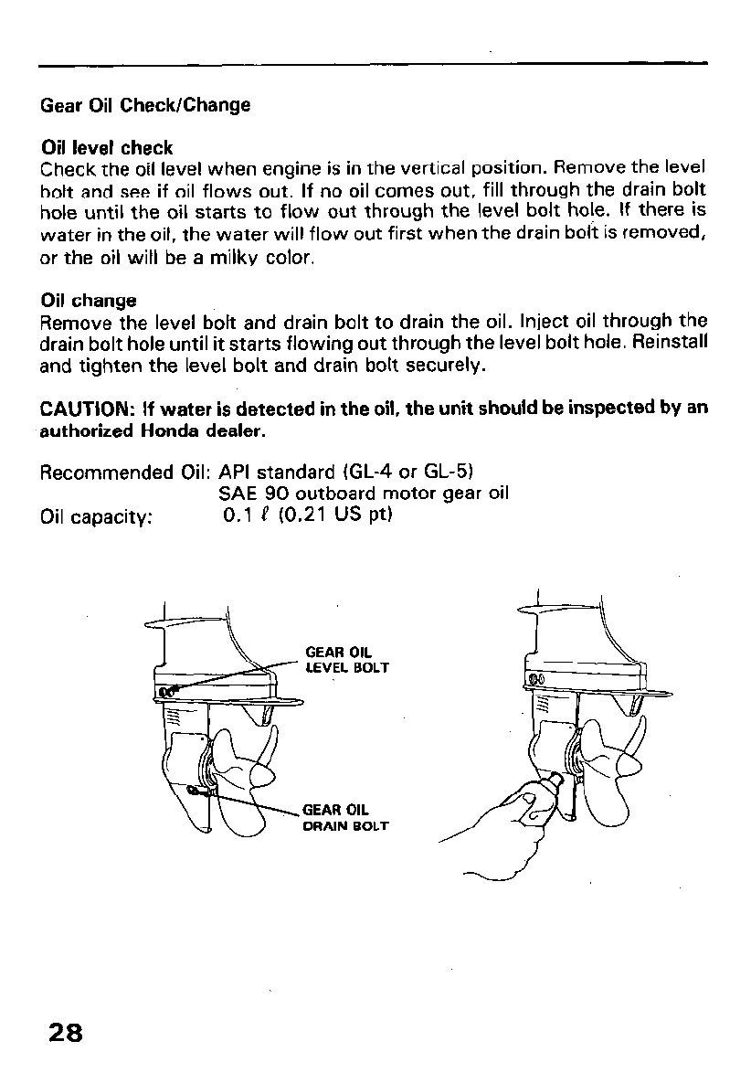
Gear Oil Check/Change
Oil level check
Check the oil level when engine is in the vertical position. Remove the level
bolt and see if oil flows out. If no oil comes out, fill through the drain bolt
hole until the oil starts to flow out through the level bolt hole. If there is
water in the oil, the water will flow out first when the drain bolt is removed,
or the oil will be a milky color.
Oil change
Remove the level bolt and drain bolt to drain the oil. Inject oil through the
drain bolt hole until it starts flowing out through the level bolt hole. Reinstall
and tighten the level bolt and drain bolt securely.
CAUTION: If water is detected in the oil, the unit should be inspected by an
authorized Honda dealer.
Recommended Oil: API standard (GL-4 or GL-5)
SAE 90 outboard motor gear oil
Oil capacity: 0.1 e (0.21 us pt)
GEAR OIL
LEVEL BOLT
GEAR OIL
DRAIN BOLT
28
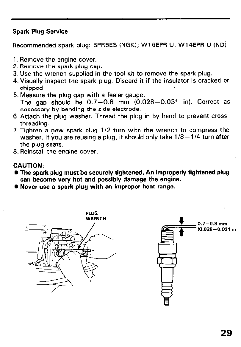
Spark Plug Service
Recommended spark plug: BPR5ES (NGK); WlGEPR-U, W14EPR-U (ND)
1. Remove the engine cover.
2. Remove the spark plug cap.
3. Use the wrench supplied in the tool kit to remove the spark plug.
4.Visually inspect the spark plug. Discard it if the insulator is cracked or
chipped.
5. Measure the plug gap with a feeler gauge.
The gap should be 0.7-0.8 mm (0.028-0.031 in). Correct as
necessary by bending the side electrode.
6. Attach the plug washer. Thread the plug in by hand to prevent cross-
threading.
7. Tighten a new spark plug l/2 turn with the wrench to compress the
washer. If you are reusing a plug, it should only take l/8- l/4 turn after
the plug seats.
8. Reinstall the engine cover.
CAUTION:
0 The spark plug must be securely tightened. An improperly tightened plug
can become very hot and possibly damage the engine.
0 Never use a spark plug with an improper heat range.
PLUG
WRENCH 0.7-0.8 mm
(0.028-0.031 in
29
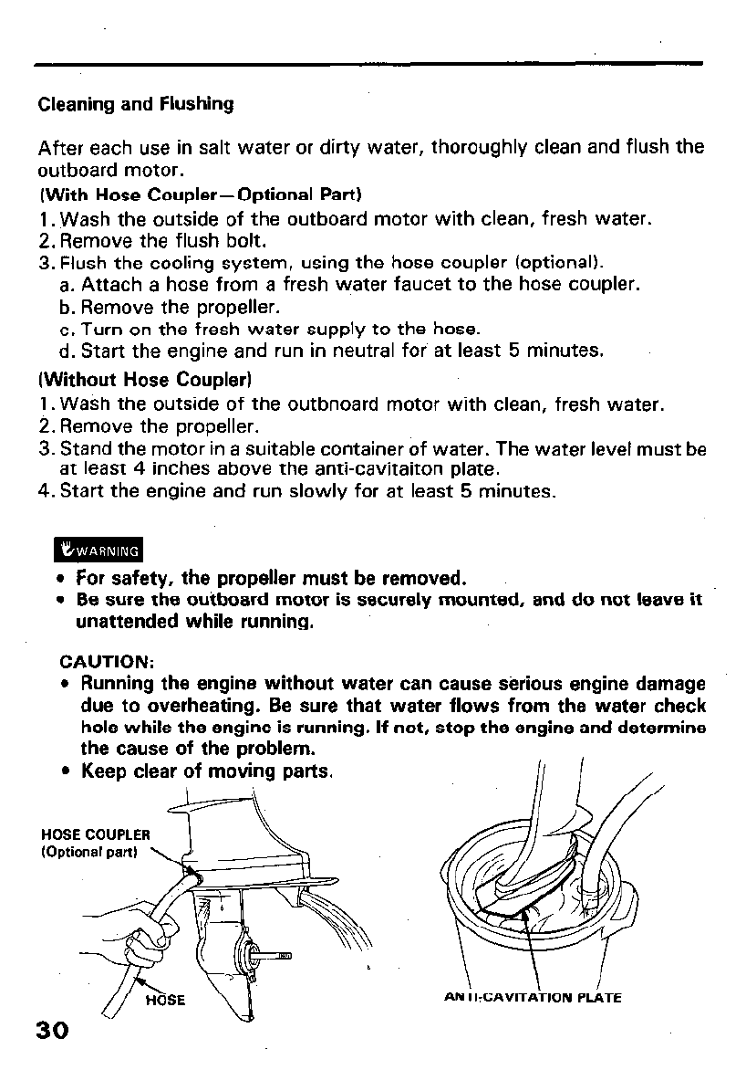
Cleaning and Flushing
After each use in salt water or dirty water, thoroughly clean and flush the
outboard motor.
(With Hose Coupler-Optional Part)
1. Wash the outside of the outboard motor with clean, fresh water.
2. Remove the flush bolt.
3. Flush the cooling system, using the hose coupler (optional).
a. Attach a hose from a fresh water faucet to the hose coupler.
b. Remove the propeller.
c. Turn on the fresh water supply to the hose.
d. Start the engine and run in neutral for at least 5 minutes.
(Without Hose Coupler)
1. Wash the outside of the outbnoard motor with clean, fresh water.
2. Remove the propeller.
3. Stand the motor i,n a suitable container of water. The water level must be
at least 4 inches above the anti-cavitaiton plate.
4. Start the engine and run slowly for at least 5 minutes.
l
For safety, the propeller must be removed.
l
Be sure the outboard motor is securely mounted, and do not leave it
unattended while running.
CAUTION:
l
Running the engine without water can cause sixious engine damage
due to overheating. Be sure that water flows from the water check
hole while the engine is running. If not, stop the engine and determine
the cause of the problem.
l
Keep clear of moving parts.
HOSE COUPLER
ANTIXAVITATION PLATE
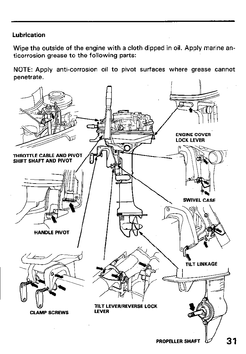
Lubrication
Wipe the outside of the engine with a cloth dipped in oil. Apply marine an-
ticorrosion grease to the following parts:
NOTE: Apply anti-corrosion oil to pivot surfaces where grease cannot
penetrate.
ENGINE COVER
LOCK LEVER
THROTTLE CABLE AN0 PIVOT
SHIFT SHAFT AND PIVOT
HANDLE PIVOT
I
TILT LINKAGE
ud
CLAMP SCREWS
TILT LEVER/REVERSE LOCK
LEVER
PROPELLER SHAFT
31

Shear Pin Change
A shear pin is used to protect the propeller and drive mechanism from damage
when the propeller strikes an obstruction.
1. Remove the cotter pin, the propeller cap, and the propeller.
2. Remove the broken shear pin and replace it with a new one.
3. Install the propeller, then install the propeller cap finger tight.
4. Install a new cotter pin, and spread the ends as shown in the illustration.
PROPELLER
COTTER-
PIN
COTTER
I i
SPARE SHEAR PINS
AND COTTER PINS
32
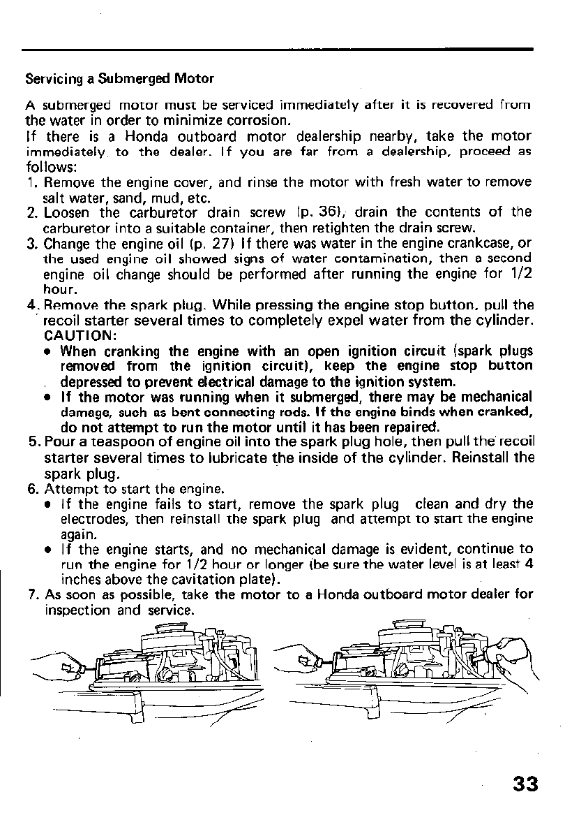
Servicing a Submerged Motor
A submerged motor must be serviced immediately after it is recovered from
the water in order to minimize corrosion.
If there is a Honda outboard motor dealership nearby, take the motor
immediately to the dealer. If you are far from a dealership, proceed as
follows:
1. Remove the engine cover, and rinse the motor with fresh water to remove
salt water, sand, mud, etc.
2. Loosen the carburetor drain screw (p. 361, drain the contents of the
carburetor into a suitable container, then retighten the drain screw.
3. Change the engine oil (p. 27) If there was water in the engine crankcase, or
the used engine oil showed signs of water contamination, then a second
engine oil change should be performed after running the engine for l/2
hour.
4. Remove the spark plug. While pressing the engine stop button, pull the
recoil starter several times to completely expel water from the cylinder.
CAUTION:
l
When cranking the engine with an open ignition circuit (spark plugs
removed from the ignition circuit), keep the engine stop button
depressed to prevent electrical damage to the ignition system.
i If the motor was running when it submerged, there may be mechanical
damage, such as bent connecting rods. If the engine binds when cranked,
do not attempt to run the motor until it has been repaired.
5. Pour a teaspoon of engine oil into the spark plug hole, then pull the’ recoil
starter several times to lubricate the inside of the cylinder. Reinstall the
spark plug.
6. Attempt to start the engine.
l
If the engine fails to start, remove the spark plug clean and dry the
electrodes, then reinstall the spark plug and attempt to start the engine
again.
l
If the engine starts, and no mechanical damage is evident, continue to
run the engine for l/2 hour or longer (be sure the water level is at least 4
inches above the cavitation plate).
7. As soon as possible, take the motor to a Honda outboard motor dealer for
insoection and service.
33
Fuel strainer replacement
The fuel strainer is located between the fuel pump and the carburetor. Water
or sediment accumulated in the fuel strainer can cause loss of power or hard
starting. To prevent engine malfuction, replace the fuel strainer regularly.
((SERVICE PERIOD)) Every 200 operating hours or every one year.
l
Gasoline is flammable and-is explosive under certain conditions.
Do
not
smoke or allow flames or sparks near the outboard motor while draining
fuel.
l
Always work in a well-ventilated area.
l
Be sure that any fuel drained from the outboard motor is stored in a safe
container.
l
Wipe up any spilled gasoline at once.
1. Disconnect the fuel tank line from the motor.
2. Remove the engine cover, and remove the fuel strainer.
NOTE: Before removing the strainer, place clamps on the fuel tubes on
each side of the strainer to prevent fuel leakage.
3. Install the new fuel strainer with the arrow mark pointing toward the
carburetor.
NOTE: Fuel flow will be impeded if the strainer is installed backward.
34
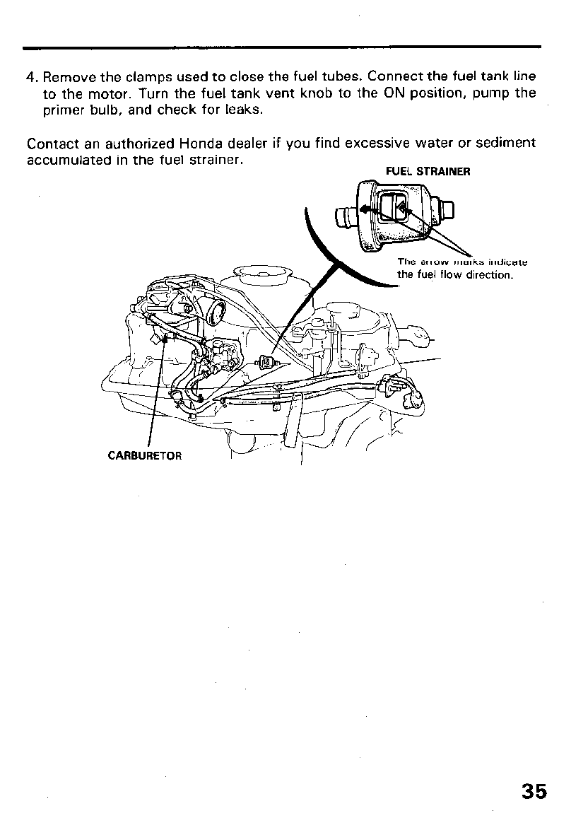
4. Remove the clamps used to close the fuel tubes. Connect the fuel tank line
to the motor. Turn the fuel tank vent knob to the ON position, pump the
primer bulb, and check for leaks.
Contact an authorized Honda dealer if you find excessive water or
accumulated in the fuel strainer.
FUEL STRAINER
sediment
arrow marks indicate
fuel flow direction.
CARBURETOR
35
10. TRANSPORTING/STORAGE
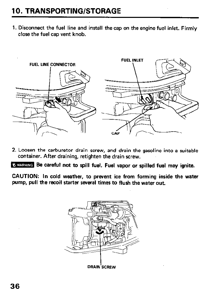
1. Disconnect the fuel line and install the cap on the engine fuel inlet. Firmly
close the fuel cap vent knob.
FUEL LINE CONNECTOR FUEL INLET r-----TdA
CAP ‘I f\--
2. Loosen the carburetor drain screw, and drain the gasoline into a suitable
container. After draining, retighten the drain screw.
m Be careful not to spill fuel. Fuel vapor or spilled fuel may ignite.
CAUTION: In cold weather, to prevent ice from forming inside the water
pump, pull the recoil starter several times to flush the water out.
DRAIN’SCREW
36
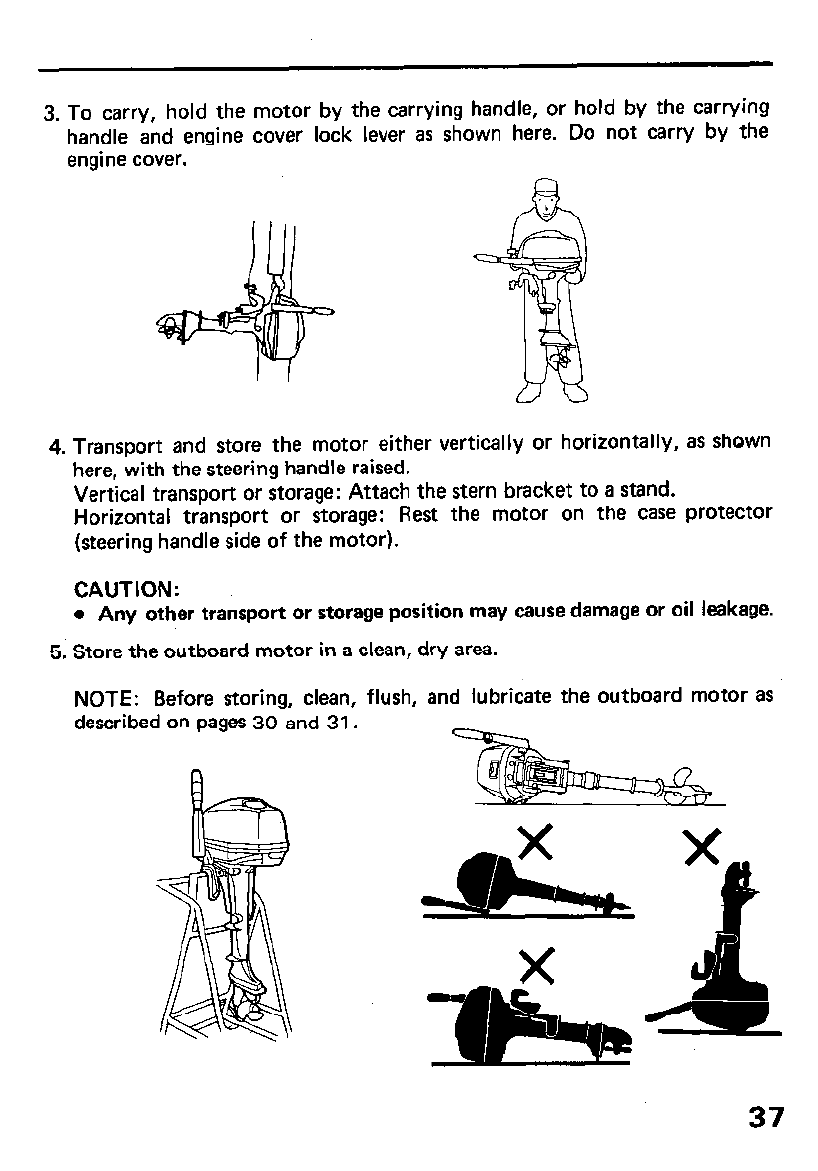
3. To carry, hold the motor by the carrying handle, or hold by the carrying
handle and engine cover lock lever as shown here. Do not carry by the
engine cover.
4. Transport and store the motor either vertically or horizontally, as shown
here, with the steering handle raised.
Vertical transport or storage: Attach the stern bracket to a stand.
Horizontal transport or storage: Rest the motor on the case protector
(steering handle side of the motor).
CAUTION:
l
Any other transport or storage position may cause damage or oil leakage.
5. Store the outboard motor in a clean, dry area.
NOTE: Before storing, clean, flush, and lubricate the outboard motor as
described on pages 30 and 31.
37
‘11. TROUBLESHOOTING
Engine Will Not Start:
1. Is the shift lever in neutral?
2. Is there fuel in the fuel tank?
3. Is the fuel cap knob turned to ON?
4. Is the fuel system primed by squeezing the primer bulb?
5. Is fuel reaching the carburetor?
Loosen the carburetor drain screw to see if there is fuel in the carburetor
float bowl.
m If any fuel is spilled, make sure the area is dry before testing the
spark plug or starting the engine. Fuel vapor and spilled fuel may ignite.
6. Are the spark plugs firing?
a. Remove and inspect the spark plugs. Clean and dry the plugs, and check
the electrode gap (p. 29). _ .;
b. Install both spark plugs in their caps, and ground the side electrodes to
each other or to any engine ground.
c. Pull the recoil starter briskly, and see if the plugs spark.
d. If the spark plugs are OK, reinstall them, and try to start the engine.
Engine Overheats:
1. Are the water intake holes clogged?
2. Is the thermostat faulty?
38
12. SPECtFlCATlONS
hem
output
Full throttle range
Engine type
Displacement
Valve tappet clearance
Specification
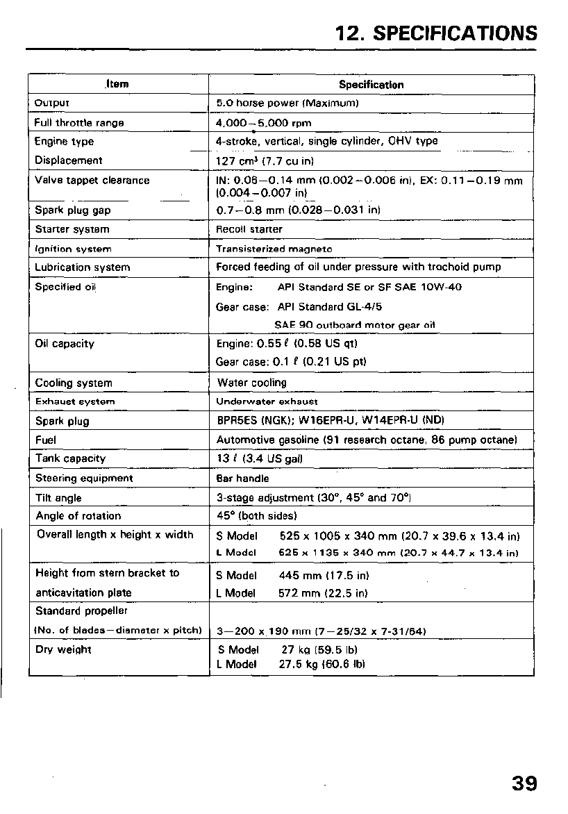
5.0 horse power IMaximum)
4,000- 5.000 rpm
4-stroke, vertical, single cylinder, OHV type
127 cm3 (7.7 cu in)
IN: 0.06-0.14 mm (0.002-0.006 in), EX: 0.1 l-0.19
mm
(0.004-0.007 in)
Spark plug gap
Starter system
Ignition system
Lubrication system
Specified oil
0.7-0.6
mm
(0.026-0.031 in)
Recoil starter
Transisterized magneto
Forced feeding of oil under pressure with trochoid pump
Engine: API Standard SE or SF SAE low-40
Gear case: API Standard GL-4/5
SAE 90 outboard motor gear oil
Oil capacity Engine: 0.55 P (0.56 US qt)
Gear case: 0.1 P (0.21 US pt)
Cooling system Water cooling
Exhaust system Underwater exhaust
Spark plug BPR5ES (NGK); WlGEPR-U, W14EPR-U (ND)
Fuel Automotive gasoline (91 research octane, 86 pump octane)
Tank capacity 13 P (3.4 US gall
Steering equipment Bar handle
Tilt angle 3-stage adjustment (30”, 45O and 70”)
Angle of rotation 45’ (both sides)
Overall length x height x width S Model 525 x 1005 x 340 mm (20.7 x 39.6 x 13.4 in)
L Model 525 x 1135 x 340 mm (20.7 x 44.7 x 13.4 in)
Height from stern bracket to S Model 445 mm (17.5 in)
anticavitation plate L Model 572 mm (22.5 in)
Standard propeller
(No. of blades-diameter x pitch) 3-200 x.190 mm (7-25/32 x 7-31/64)
Dry weight S Model 27 kg (59.5 lb)
L Model 27.5 kg (60.6 lb)
39
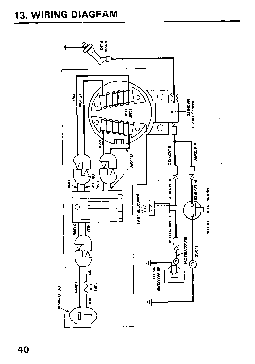
13. WIRING DIAGRAM
40
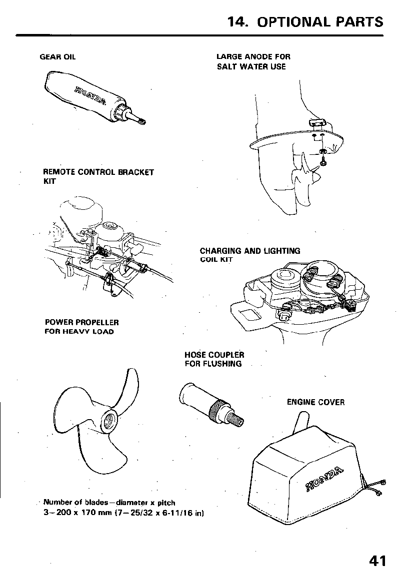
14. OPTIONAL PARTS
GEAR OIL
REMOTE CONTROL BRACKET
KIT
POWER PROPELLER
FOR HEAVY LOAD
n
LARGE ANODE FOR
SALT WATER USE
CHARGING AND LIGHTING
COIL KIT
HOSE COUPLEk
FOR FLUSHING
ENGINE COVER
n
Number of blades-diameter x pitch
3-200 x 170 mm (7-25/32 x 6-11/16 in)
41
15. WARRANTY SERVICE
Owner Satisfaction
Your satisfaction and goodwill are important to your dealer and to us. All
Honda warranty details are explained in the Distributor’s Limited Warranty.
Normally, any problems concerning the product will be handled by your
dealer’s service department. If you have a warranty problem that has not
been handled to your satisfaction, we suggest you take the following
action:
l Discuss your problem with a member of dealership management. Often
complaints can be quickly resolved at that level. If the problem has
already been reviewed with the Service Manager, contact the owner of
the dealership or the General Manager.
l If your problem still has not been resolved to your satisfaction, contact
the Power Equipment Customer Relations Department of American
Honda Motor Co., Inc.
American Honda Motor Co., Inc.
Power Equjpment Customer Relations Department
P.O. Box 50
Gardena, California 90247-0805
Telephone:
(213) 604-2400
We will need the following information in order to assist you:
- Your name, address, and telephone number
- Product model and serial number
- Date of purchase
- Dealer name and address
- Nature of the problem
After reviewing all the facts involved, you will be advised of what action
can be taken. Please bear in mind that your problem will likely be resolved
at the dealership, using the dealer’s facilities, equipment, and personnel, so
it is very important that your initial contact be with the dealer.
Your purchase of a Honda product is greatly appreciated by both your
dealer and American Honda Motor Co., Inc. We want to assist you in every
way possible to assure your complete satisfaction with your purchase.
42
Current customer service contact information:
Your owner's manual was written to cover most of the questions you might ask about
your Honda. Any questions not answered in the owner's manual can be answered by
your Honda dealer. If your dealer doesn't have an immediate answer, they should be
able to get it for you.
If you have a difference of opinion with your dealer, please remember that each
dealership is independently owned and operated. That's why it's important to work to
resolve any differences at the dealership level. If the service personnel are unable to
assist you, please discuss your concerns with the dealer management such as the
Service Manager or the dealership's owner.
If you need to contact American Honda regarding your experiences with your Honda
product or with your dealer, please send your comments to the following address:
American Honda Motor Co., Inc.
Marine Division
Customer Relations Office
4900 Marconi Drive
Alpharetta, GA 30005-8847
Or telephone: (770) 497-6400 M-F, 8:30 am - 7:00 pm EST
When you write or call, please provide the following information:
• Your name, address and telephone number (complete with area code)
• Model and complete serial number
• Date of purchase
• Name and location of the selling dealer
• Name and location of the servicing dealer (if different)
• A detailed description of your concerns

MEMO
43

MEMO
44