Honda Bf9 9 Babl 1000001 1199999 Owners Manual
Outboard Motor BF9.9A/15A 31ZV4600
2014-11-13
: Honda Honda-Bf9-9-Babl-1000001-1199999-Owners-Manual-108017 honda-bf9-9-babl-1000001-1199999-owners-manual-108017 honda pdf
Open the PDF directly: View PDF ![]() .
.
Page Count: 81

Thank you for purchasing a Honda Outboard Motor.
This manual covers operation and, maintenance of the Honda BF9.9A/15A
Outboard Motor. All information in this publication is based on the latest
product information available at the time of approval for printing.
Honda Motor Co., Ltd. reserves the right to make changes at any time
without notice and without incurring any obligation.
No part of this publication may be reproduced without written permission.
This manual should be considered a permanent part of the Outboard Motor
and should remain with it if it is resold.
Pay special attention to statements preceded by the following words:
A DANGER: indicates severe personal injury or death will result if instruc-
tions .are not followed.
m Indicates a strong possibility of severe personal injury or death if
instructions are not followed.
CAUTION: Indicates a possibility of personal injury or equipment damage
if instructions are not followed.
NOTE: Gives helpful information.
If a problem should arise, or if you have any questions about the Outboard
Motor, consult an authorized Honda Outboard Motor dealer.
Illustrations are mainly based on BF15A LAS type.
1
CONTENTS
1 . SAFETY .............................................................................. 3
2. COMPONENT IDENTIFICATION .............................................. 5
3. INSTALLATION .................................................................... 7
4. PRE-OPERATION CHECK ....................................................... 11
5. STARTING THE ENGINE ........................................................ 15
6. OPERATION ........................................................................ 21
l
High altitude operation ....................................................... 26
7. STOPPING THE ENGINE ......................................................... 27
8. MAINTENANCE ................................................................... 28
9. TRANSPORTING/STORAGE ................................................... 42
10. TROUBLESHOOTING ............................................................ 46
11. SPECIFICATIONS ................................................................. 47
12. WIRING DIAGRAM ............................................................... 49
13. OPTIONAL PARTS ....... . ......................................................... 51
14. WARRANTY SERVICE ........................................................... 52
2
1. SAFETY
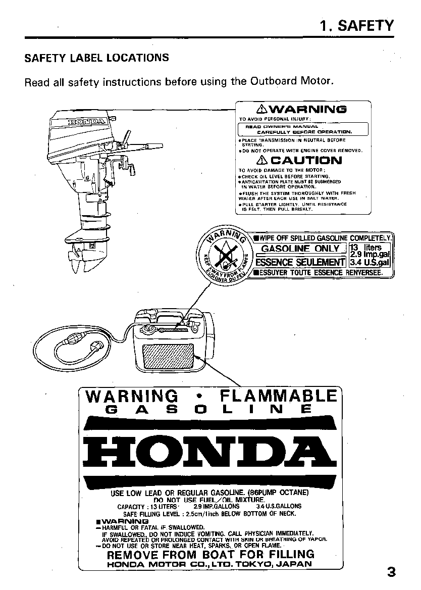
SAFETY LABEL LOCATIONS
Read all safety instructions before using the Outboard Motor.
STRTINO.
.DO NOT OPERATE WITH ENC-~- --. -- ~----..-
A CAU’. .-.w
T”
a”“,” r’----
- -\ \
[WARNING
l
FLAMMABLE
GASOLINE
HONDA
USE LOW LEAD OR REGULAR GASOLINE. (88PUMP OCTANE)
DO NOT USE FUEL/OIL MIXTURE.
CAPACITY : 13 LITERS 2.9 IMP.GALLONS 3.4~U.S.GALLONS
SAFE FILLING LEVEL : 2Scm/linch BELOW BOTTOM OF NECK.
n
WARNINQ
-HARMFUL OR FATAL IF SWALLOWED.
IF SWALLOWED., DO NOT INDUCE VOMITING. CALL PHYSICIAN IMMEDIATELY.
AVOID REPEATED OR PROLONGED CONTACT WITH SKIN OR BREATHING OF VAPOR.
-DO NOT USE OR STORE NEAR MEAT, SPARKS,. OR OPEN FLAME.
REMOVE FROM BOAT FOR FILLING
HONOA MOTOR CO.. LTD. TOKYO. JAPAP
3
SAFETY INSTRUCTIONS
mm
Honda Outboard motors are designed to give safe dependable
service if operated according to instructions. Read-and understand the
Owner’s Manual before operating the Outboard Motor. Failure to do so
could result in personal injury or equipment damage.
To avoid severe personal injury or equipment damage, observe the follow-
ing precautions:
l
Understand the operation of all controls, and know how to stop the
engine quickly- READ THIS OWNER’S MANUAL CAREFULLY.
l
Do not exceed the boat manufacturer’s power recommendation, and be
sure the outboard motor is properly mounted.
l
Never permit anyone to operate the outboard motor without proper
instruction.
l
Stop the engine immediately if anyone falls overboard.
l
Do not run the motor while the boat is near anyone in the water.
l
Exhaust contains poisonous carbon monoxide which can cause un-
consciousness and may lead to death. Never run the outboard in a clos-
ed garage or confined area.
l
Gasoline is extremely flammable and is explosive under certain condi-
tions. Refuel in a well ventilated area with the engine stopped. Do not
smoke or allow flames or sparks where the engine is iefueled or where
gasoline is stored.
l
Do not overfill the fuel tank. After refueling make sure that the fuel tank
cap is closed properly and securely.
l
Be careful not to spill any fuel while refueling. Spilled fuel or fuel vapor
may ignite. If any fuel is spilled make sure that the area is dry before
starting the engine.
l
Do not remove any guards, labels, shields, covers or safety devices;
they are installed for your safety.
4
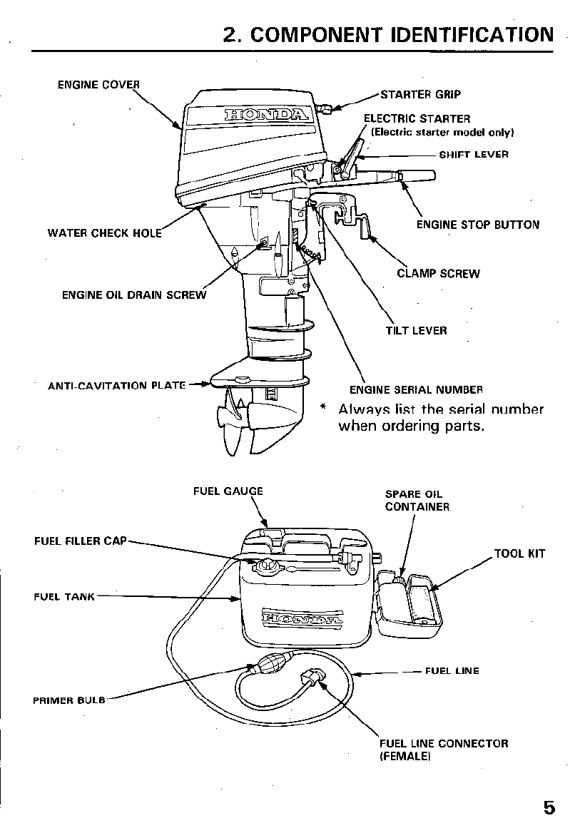
2. COMPONENT IDENTIFICATION
ENGINE COV;\ ~ ~ I ,STARTER GRIP
LECTRIC STARTER
(Electric starter model only)
SHIFT LEVER
WATER CHECK HOLE NGINE STOP BUTTON
ENGINE OIL DRAIN SCRE
AMP SCREW
TILT LEVER
ANTI-CAVITATION PLATE \
ENGINE SERIAL NUMBER
* Always list the serial number
when ordering parts.
FUEL GAUGE
\
SPARE OIL
CONTAINER
FUEL FILLER CAP TOOL KIT
FUEL TANK
PRIMER BULB
‘FUEL LINE CONNECTOR
(FEMALE)
5
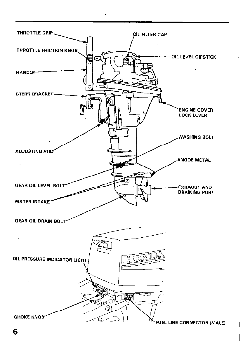
OIL FILLER CAP
I
THROTTLE GRIP
THROTTLE FRICTION KNOB
OIL LEVEL DIPSTICK
HANDLE
STERN BRACKET.
LOCK LEVER
ADJUSTING ROD
ANODE METAL
GEAR OIL LEVEL BOL EXHAUSTAND
DRAINING PORT
WATER INTAKE
GEAR OIL DRAIN BOLT’
OIL PRESSURE INDICATOR LIG
CHOKE KNOB FUEL LINE CONNECTOR (MALE)
6
3. INSTALLATION
It is your responsibility to choose a boat suitable for the engine (9.9
horsepower BF9.9A, 15 horsepower BF15A).
mm Do not exceed the boat manufacturer’s power recommenda-
tion. Damage and injury may result.
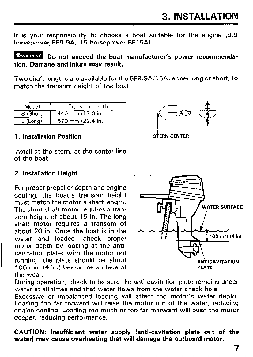
Two shaft lengths are available for the BF9.9A/15A, either long or short, to
match the transom height of the boat.
1. Installation Position
S!ERN CENTER
Install at the stern, at the center Me
of the boat.
2. Installation Height
For proper propeller depth and engine
cooling, the boat’s transom height
must match the motor’s shaft length.
The short shaft motor requires a tran-
som height of about 15 in. The long
shaft motor requires a transom of
about 20 in. Once the boat is in the
water and loaded, check proper
motor depth by looking at the anti-
cavitation plate: with the motor not
running, the plate should be about
100 mm (4 in.) below the surface of
the wear.
TER SURFACE
PLATE
During operation, check to be sure the anti-cavitation plate remains under
water at all times and that water flows from the water check hole.
Excessive or imbalanced loading will affect the motor’s water depth.
Loading too far forward will raise the motor out of the water, reducing
engine cooling. Loading too much or too far rearward will push the motor
deeper, reducing performance.
CAUTION: Insufficient water supply (anti-cavitation plate out of the
water) may cause overheating that will damage the outboard motor.
7
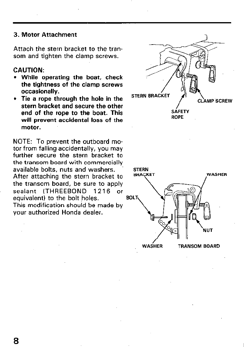
3. Motor Attachment
Attach the stern bracket to the tran-
som and tighten the clamp screws.
CAUTION:
l
While operating the boat, check
the tightness of the clamp screws
occasionally.
l
Tie a rope through the hole in the
stern bracket and secure the other
end of the rope to the boat. This
will prevent accidental loss of the
motor.
NOTE: To prevent the outboard mo-
tor from falling accidentally, you may
further secure the stern bracket to
the transom board with commercially
available bolts, nuts and washers.
After attaching the stern bracket to
the transom board, be sure to apply
sealant (THREEBOND 1216 or
SAFETY
ROPE
STERN
BRACKET WASHER
\ /
eouivalent) to the bolt holes.
BOL
This modification should be made by
your authorized Honda dealer.
WAS-HER TRANSOM BOARD
8
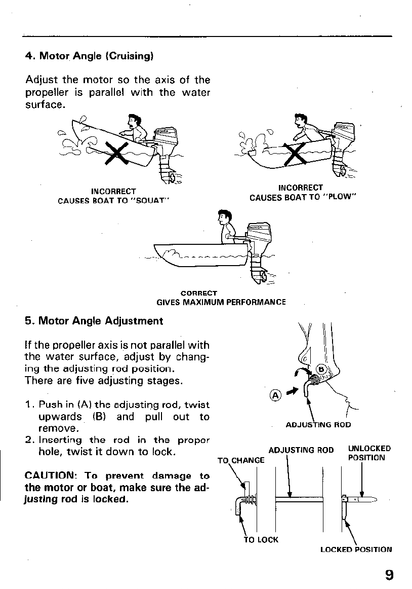
4. Motor, Angle (Cruising)
Adjust the motor so the axis of the
propeller is parallel with the water
surface.
INCORRECT
CAUSES BOAT TO “SQUAT”
INCORRECT
CAUSES BOAT TO “PLOW”
CORRECT
GIVES MAXIMUM PERFORMANCE
5. Motor Angle Adjustment
If the propeller axis is not parallel with
the water surface, adjust by chang-
ing the adjusting rod position.
There are five adjusting stages.
1. Push in (A) the adjusting rod, twist @a
upwards (B) and pull out to
remove.
ADJUSTING ROD
2. Inserting the rod in the proper
hole, twist it down to lock.
ADJUSTING ROD UNLOCKED
TO CHANGE POSITION
CAUTION: To prevent damage to
the motor or boat, make sure the ad-
justing rod is locked.
3pf,
. 0
TO LOCK LOCKED POSITION
9
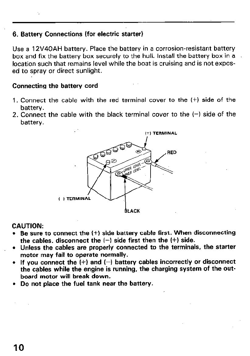
6. Battery Connections (for electric starter)
Use a 12V40AH battery. Place the battery in a corrosion-resistant battery
box and fix the battery box securely to the hull. Install the battery box in a
location such that remains level while the boat is cruising and is not expos-
ed to spray or direct sunlight.
Connecting the battery cord
1. Connect the cable with the red terminal cover to the (+I side of the
battery.
2. Connect the cable with the black terminal cover to
battery.
(+I TERMINAL
the (-1 side of the
(-1 TERMIN
CAUTION:
l
Be sure to connect the (+) side battery cable first. When disconnecting
the cables, disconnect the (-) side first then the (+I side.
l
Unless the cables are properly connected to the terminals, the starter
motor may fail to operate normally.
l
If you connect the (+) and (-) battery cables incorrectly or disconnect
the cables while the engine is running, the charging system of the out-
board motor will break down.
l
Do not place the fuel tank near the battery.
IO
4. PRE-OPERATION CHECKS
1. Engine Oil Level
CAUTION:
l
Engine oil is a major factor affecting engine performance and service life.
Nondetergent and low quality oils are not recommended, because they
have inadequate lubricating properties.
l
Running the engine with insufficient oil can cause serious engine
. damage.
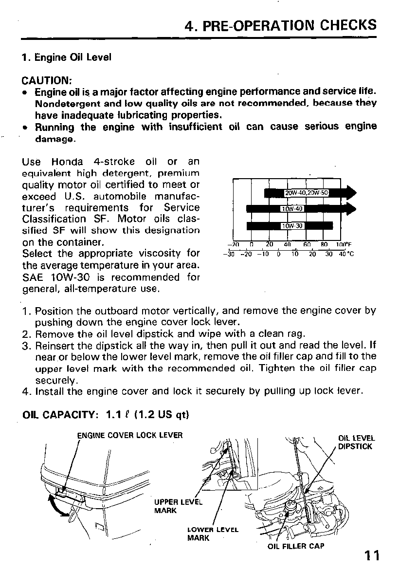
UsB Honda 4-stroke oil or an
equivalent high detergent, premium
quality motor oil certified to meet or
exceed U.S. automobile manufac-
turer’s requirements for Service
Classification SF. Motor oils clas-
sified SF will show this designation
on the container.
Select the appropriate viscosity for
the average temperature in your area.
SAE low-30 is recommended for
general, all-temperature use.
-& -50 -io b lb ’ ’ 20
30 4O’C
1. Position the outboard motor vertically, and remove the engine cover by
pushing down the engine cover lock lever.
2. Remove the oil level dipstick and wipe with a clean rag.
3. Reinsert the dipstick all the way in, then pull it out and read the level. If
near or below the lower level mark, remove the oil filler cap and fill to the
upper level mark with the recommended oil. Tighten the oil filler cap
securely.
4. Install the engine cover and lock it securely by pulling up lock lever.
OIL CAPACITY: 1.1 ! (1.2 US qt)
NGINE COVER LOCK LEVER
OIL FILLER CAP
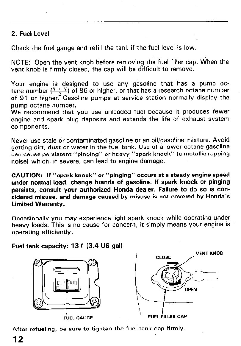
2. Fuel Level
Check the fuel gauge and refill the tank if.the fuel level is low.
NOTE: Open the vent knob b’efore removing the fuel filler cap. When the
vent knob is firmly clbsed, the cap will be difficult to remove.
Your engine is designed to use any gasoline that has a pump oc-
tane number lR + M, of 86 or higher, or that has a research octane number
of 91 or higher.* Gasoline pumps at service station normally display the
pump octane number.
We recommend that you use unleaded fuel because it produces fewer
engine and spark plug deposits and extends the life of exhaust system
components.
Never use stale or contaminated gasoline or an oil/gasoline mixture. Avoid
getting dirt, dust or water in the fuel tank. Use of a lower octane gasoline
can cause persistent “pinging” or heavy “spark knock” (a metallic rapping
noise) which, if severe, can lead to engine damage.
CAUTION: If “spark knock” or “pinging” occurs at a steady engine speed
under normal load, change brands of gasoline. If spark knock or pinging
persists, consult your authorized Honda dealer. Failure to do so is con-
sidered misuse, and damage caused by misuse is not covered by Honda’s
Limited Warranty.
Occasionally you may experience light spark knock while operating under
heavy loads. This is no cause for concern, it simply means your engine is
operating efficiently.
Fuel tank capacity: 13 P (3.4 US gal)
FUEL GAUGE
After refueling, be sure to tighten the fuel tank cap firmly.
12
l
Gasoline is extremely flammable and is explosive under certain
conditions.
l
Refuel in a well-ventilated area with the engine stopped. Do not smoke
or allow flames or sparks in the area where the engine is refueled or
where gasoline is stored.
l
Do not overfill the tank (there should be no fuel in the filler neck). After
refueling, make sure the tank cap is closed properly and securely.
l
Be careful not to spill fuel when refueling. Spilled fuel or fuel vapor may
ignite. If any fuel is spilled, make sure the area is dry before starting the
engine. --.
l
Avoid ‘repeated or prolonged contact with skin or breathing of vapor.
KEEP OUT OF REACH OF CHILDREN.
GASOLINES CONTAINING ALCOHOL
If you decide to use a gasoline containing alcohol (gasohol), be sure it’s oc-
tane rating is at least as high as that recommended by Honda. There are
two types of “gasohol”: one containing ethanol, and the other containing
methanol. Do not use gasohol that contains more than 10% ethanol. Do
not use gasoline containing methanol (methyl or wood alcohol) that does
not also contain cosolvents and corrosion inhibitors for methanol. Never
use gasoline containing more than 5% methanol, even if it has cosolvents
and corrosion inhibitors.
NOTE:
l
Fuel system damage or engine performance problems resulting from the
use of fuels that contain alcohol is not covered under the warranty.
Honda cannot endorse the use pf fuels containing methanol since
evidence of their suitability is as yet incomplete.
l
Before buying fuel from an unfamiliar station, try to find out the fuel con-
tains alcohol, if it does, confirm the type and percentage of alcohol us-
ed. If you notice any undesirable operating symptoms while using a
gasoline that contains alcohol, or one that you think contains alcohol,
switch to a gasoline that you know does not contain alcohol.
13
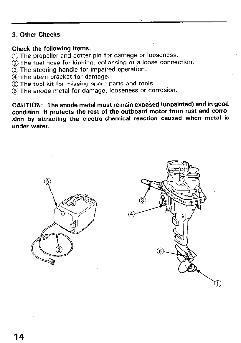
3. Other Checks
Check the following items.
@ The propeller and cotter pin for damage or looseness.
@The fuel hose for kinking, collapsing or a loose connection.
@The steering handle for impaired operation.
@The stern bracket for damage.
@The tool kit for missing spare parts and tools.
@The anode metal for damage, looseness or corrosion.
CAUTION: The anode mdtal must remain exposed (unpainted) and in good
condition. It protects the rest of the outboard motor from rust and corro-
sion by attracting the electro-chemical reaction caused when metal is
under water.
14
5. STARTING THE ENGINE
1. Preparation Before Starting
CAUTION: To prevent damage to the outboard from overheating, never
run the engine with the propeller out of the water.
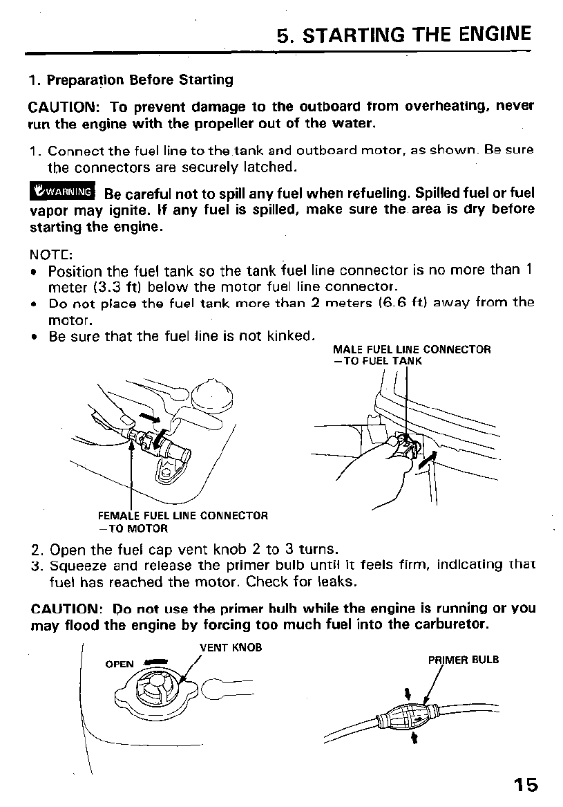
1. Connect the fuel line to the.tank and outboard motor, as shown. Be sure
the connectors are securely latched.
mm
Be careful not to spill any fuel when refueling. Spilled fuel or fuel
vapor may ignite. If any fuel is spilled, make sure the. area is dry before
starting the engine.
NOTE:
l
Position the fuel tank so the tank fuel line connector is no more than 1
meter (3.3 ft) below the motor fuel line connector.
l
Do not place the fuel tank more than 2 meters (6.6 ft) away from the
motor.
l
Be sure that the fuel line is not kinked.
MALE FUEL LINE CONNECTOR
-TO FUEL TANK
-TO MOTOR
2. Open the fuel cap vent knob 2 to 3 turns.
3. Squeeze and release the primer bulb until it feels firm, indicating that
fuel has reached the motor. Check for leaks.
CAUTION: Do not use the primer bulb while the engine is running or you
may flood the engine by forcing too much fuel into the carburetor.
I
VENT KNOB
\
15
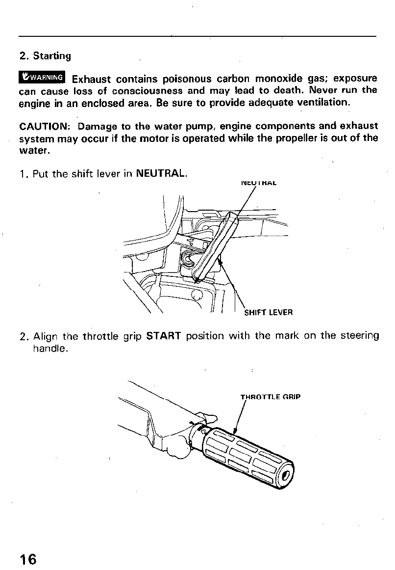
2. Starting
BMlm Exhaust contains poisonous carbon monoxide gas; exposure
can cause loss of consciousness and may lead to death. Never run the
engine in an enclosed area. Be sure to provide adequate ventilation.
CAUTION: Damage to the water pump, engine components and exhaust
system may occur if the motor is operated while the propeller is out of the
water.
1. Put the shift lever in NEUTRAL.
NEYTRAL
2. Align the throttle grip START position with the mark on the steering
handle.
16
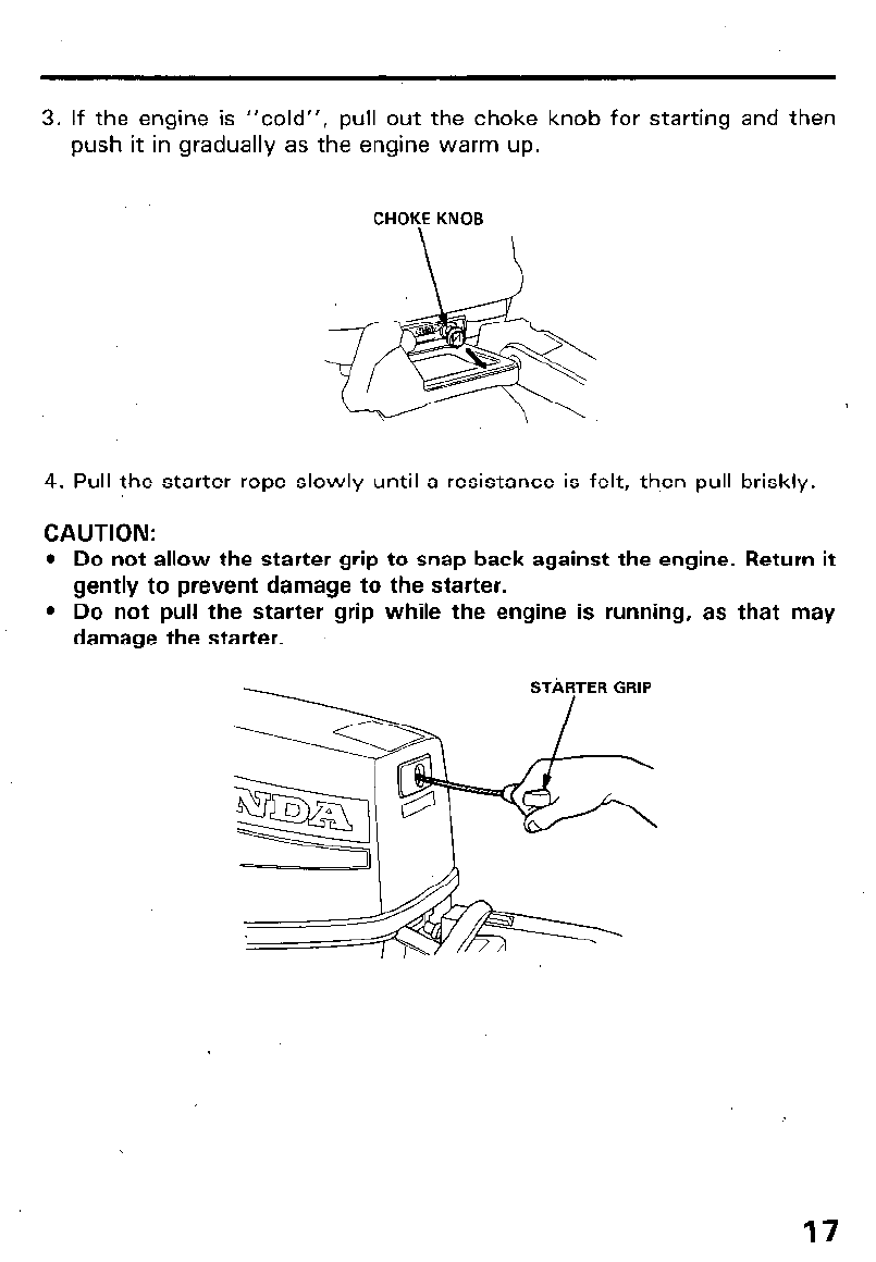
3. If the engine is “cold”, pull out the choke knob for starting and then
push it in gradually as the engine warm up.
CHOKE KNOB
4. Pull the starter rope slowly until a resistance is felt, th.en pull briskly.
CAUTION:
l
Do not allow the starter grip to snap back against the engine. Return it
gently to prevent damage to the starter.
l
Do not pull the starter grip while the engine is running, as that may
damage the starter.
17
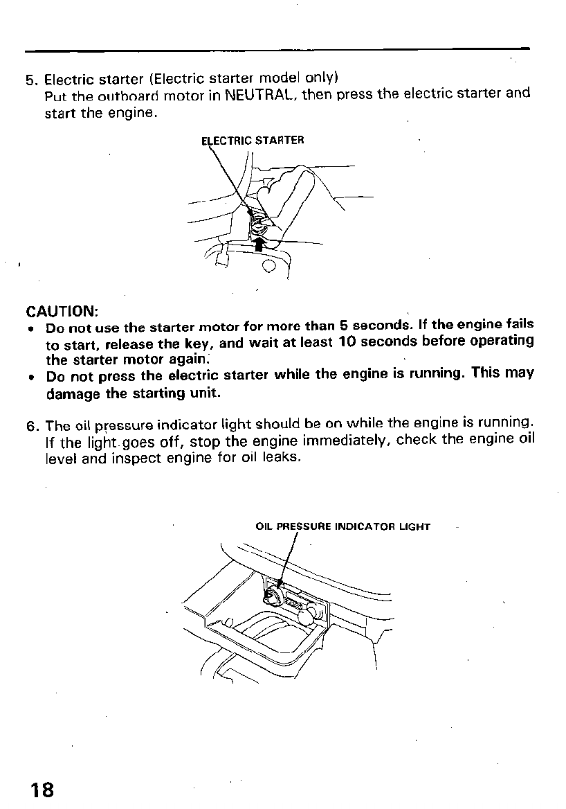
5. Electric starter (Electric starter model only)
Put the outboard motor in NEUTRAL, then press the electric starter and
start the engine.
ECECTRIC STARTER
CAUTION:
l
Do not use the starter motor for more than 5 seconds. If the engine fails
to start, release the key, and wait at least 10 seconds before operating
the starter motor again;
0 Do not press the electric starter while the engine is running. This may
damage the starting unit.
6. The oil pressure indicator light should be on while the engine is running.
If the lightgoes off, stop the engine immediately, check the engine oil
level and inspect engine for oil leaks.
OIL PREFSURE INDICATOR LIGHT -
18
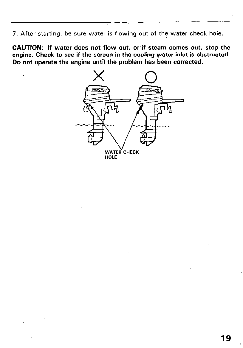
7. After starting, be sure water is flowing out of the water check hole.
CAUTION: If water does not flow out, or if steam comes out, stop the
engine. Check to see if the screen in the cooling water inlet is obstructed.
Do not operate the engine until the problem has been corrected.
X 0
WATEd CHECK
HOLE
19
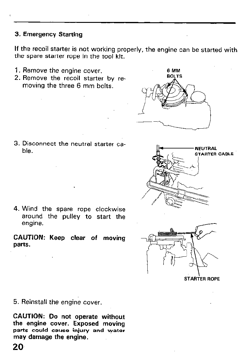
3. ,Emergency Starting
If the recoil starter is not working properly, the engine can be started with
the, spare starter rope in the tool kit.
1. Remove the engine cover.
2. Remove the recoil starter by re-
moving the three 6 mm bolts.
3. Disconnect the neutral starter ca-
ble.
4. Wind the spare rope clockwise
around the pulley to start the
engine.
CAUTION: Keep clear of moving
parts.
5. Reinstall the engine cover.
6MM
BOLTS
I”- NEUTRAL CABLE
STARTER ROPE
CAUTION: Do not operate without
the engine cover. Exposed moving
parts could cause injury and \?rater
may damage the engine.
20
6. OPERATION
For the first 10 hours of operation, run the outboard motor at low speed,
and avoid abrupt operation of the throttle.
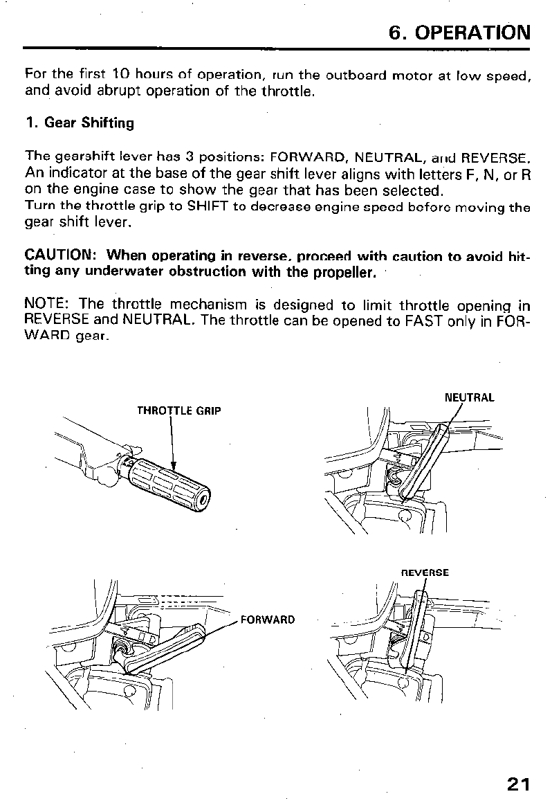
1. Gear Shifting
The gearshift lever has 3 positions: FORWARD, NEUTRAL, and REVERSE.
An indicator at the base of the gear shift lever aligns with letters F, N, or R
on the engine case to show the gear that has been selected.
Turn the throttle grip to SHIFT to decrease engine speed before moving the
gear shift lever.
CAUTION: When operating in reverse, proceed with caution to avoid hit-
ting any underwater obstruction with the propeller.
NOTE: The throttle mechanism is designed to limit throttle opening in
REVERSE and NEUTRAL. The throttle can be opened to FAST only in FOR-
WARD gear.
THROTTLE GRIP
NEUTRAL
REVERSE
FORWARD
21
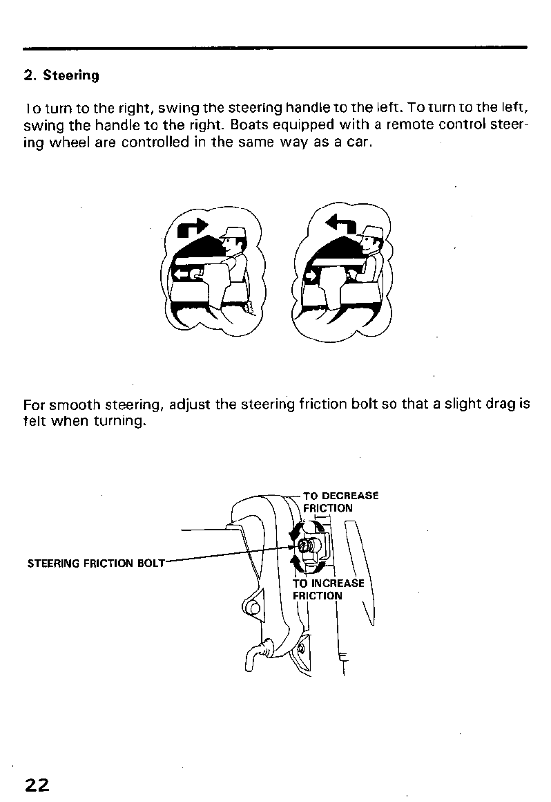
2. Steering
To turn to the right, swing the steering handle to the left. To turn to the left,
swing the handle to the right. Boats equipped with a remote control steer-
ing wheel are controlled in the same way as a car.
For smooth steering, adjust the steering friction bolt so that a slight drag is
felt when turning.
STEERING FRICTION BOLT-
22
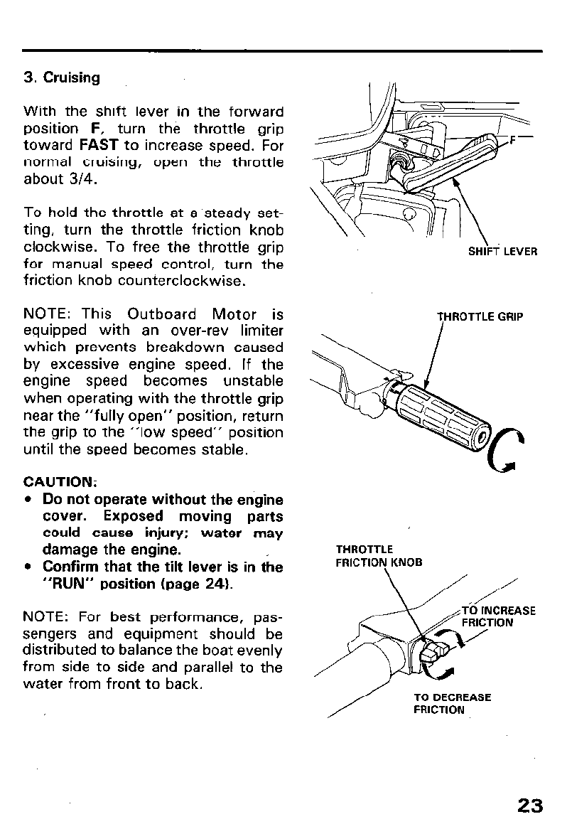
3. Cruising
With the shift lever in the forward
position F, turn the throttle grip
toward FAST to increase speed. For
normal cruising, open the throttle
about 3/4.
To hold the throttle at a ‘steady set-
ting, turn the throttle friction knob
clockwise. To free the throttle grip
for manual speed control, turn the
friction knob counterclockwise.
NOTE: This Outboard Motor is
equipped with an over-rev limiter
which prevents breakdown caused
by excessive engine speed. If the
engine speed becomes unstable
when operating with the throttle grip
near the “fully open” position, return
the grip to the “low speed” position
until the speed becomes stable.
CAUTION:
l
Do not operate without the engine
cover. Exposed moving parts
could cause injury; water may
damage the engine.
l
Confirm that the tilt lever is in the
“RUN” position (page 24).
NOTE: For best performance, pas-
sengers and equipment should be
distributed to balance the boat evenly
from side to side and parallel to the
water from front to back.
SH;\Fi LEVER
THROTTLE
FRICTION KNOB
SE
TO DECREASE
FRICTION
23
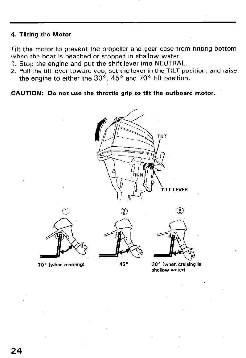
4. Tilting the Motor
Tilt the motor to prevent the propeller and gear case from hitting bottom
when the boat is beached or stopped in shallow water.
1. Stop the engine and put the shift lever into NEUTRAL.
2. Pull the tilt lever toward you, set the lever in the TILT position, and raise
the engine to either the 30”, 45’ and 70’ tilt position.
CAUTION: Do not use the throttle grip to tilt the outboard motor.
70” (when mooring)
LEVER
30° (when cruising in
shallow water)
24
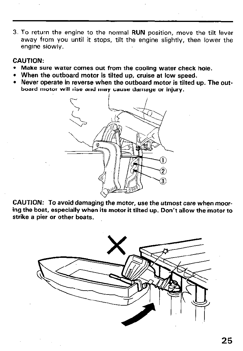
3. To return the engine to the normal RUN position, move the tilt lever
away from you until it stops, tilt the engine slightly, then lower the
engine slowly.
CAUTION:
l
Make sure water comes out from the cooling water check hole.
l
When the outboard motor is tilted up, cruise at low speed.
l
Never operate in reverse when the outboard motor is tilted up. The out-
board motor will rise and may
cause
damage or injury.
I
CAUTION: To avoid damaging the motor, use the utmost care when moor-
ing the boat, especially when its motor it tilted up. Don’t allow the motor to
strike a pier or other boats.
25
5. High altitude operation
At high altitude, the standard carburetor air-fuel mixture will be excessively
rich. performance will decrease, and fuel consumption will increase.
High altitude performance can be improved by installing a smaller diameter
main fuel jet in the carburetor and readjusting the pilot screw. If you always
operate the outboard motor at altitudes higher than 6,000 feet above sea
level, have your authorized Honda Outboard Motor dealer perform these
carburetor modifications.
Even with suitable carburetor jetting, engine horsepower will decrease ap-
proximately 3.5% for each 1,000 foot increase in altitude. The affect of
altitude on horsepower will be greater than this if no carburetor modifica-
tion is made.
CAUTION: Operation of the outboard motor at an altitu,de lower than the
carburetor is jetted for may result in reduced performance, overheating,
and serious engine damage caused by an excessively lean air/fuel mixture.
26
I
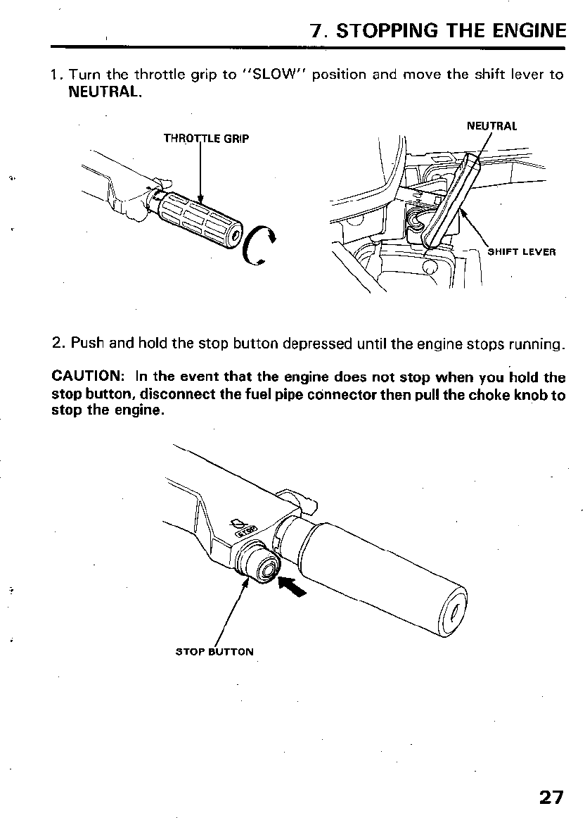
7. STOPPING THE ENGINE
1. Turn the throttle grip to “SLOW” position and move the shift lever to
NEUTRAL.
NEUTRAL
2. Push and hold the stop button depressed until the engine stops running.
CAUTION: In the event that the engine does not stop when you hold the
stop button, disconnect the fuel pipe cdnnector then pull the choke knob to
stop the engine.
STOP BUTTON
27
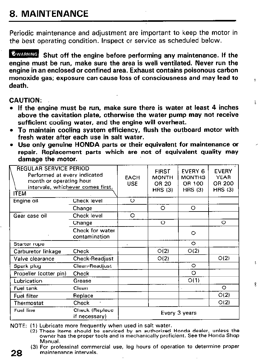
8. MAINTENANCE
Periodic maintenance and adjustment are important to keep the motor in
the best operating condition. Inspect or service as scheduled below.
m Shut off the engine before performing any maintenance. If the
engine must be run, make sure the area is well ventilated. Never run the
engine in an enclosed or confined area. Exhaust contains poisonous carbon
monoxide gas; exposure can cause loss of consciousness and may lead to
death.
CAUTION: 3
l
If the engine must be run, make sure there is water at least 4 inches
above the cavitation plate, otherwise the water pump may not receive
sufficient cooling water, and the engine will overheat.
l
To maintain cooling system efficiency, flush the outboard motor with
fresh water after each use in salt water.
l
Use only genuine HONDA parts or their equivalent for maintenance or ’
repair. Replacement parts which are not of equivalent quality may
damage the motor.
REGULAR SERVICE PERIOD
Performed at every indicated FIRST EVERY 6 EVERY
month or operating hour EACH MONTH MONTHS YEAR
intervals, whichever comes first. USE OR 20 OR 100 OR 200
ITEM. \ HRS (3) HRS (3) HRS (3)
Engine oil
r
Gear case oil
Check leve
!I I 0 I
Change 0 0
Check level 0
Change 0 0
Check for water
contamination 0
0
Check
O(2) O(2)
Check-Readjust
O(2)
O(2)
Clean-Readjust 0
Check 0
Lubrication
Fuel tank
Grease
Clean
O(1) &
0
Fuel filter
Thermostat
Fuel line
Replace
Check .
Check (Replace
if necessary)
1
O(2)
1
O(2)
Every 3 Years
NOTE: (1) Lubricate more frequently when used in salt water.
(2) These items should be serviced by an authorized Honda dealer, unless the
owner has the proper tools and is mechanically proficient. See the Honda Shop
Manual.
(3) For professinal commercial use, log hours of operation to determine proper
28
maintenance intervals.
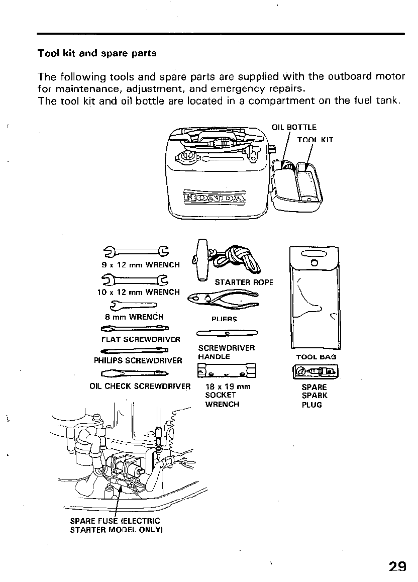
Tool kit and spare parts
The following tools and spare parts are supplied with the outboard motor
for maintenance, adjustment, and emergency repairs.
The tool kit and oil bottle are located in a compartment on the fuel tank.
9 x 12 mm WRENCH
STARTER ROPE
10 x 12 mm WRENCH
8 mm WRENCH PLIERS
c=- 3 C Q >
FLAT SCREWDRIVER
e a SCREWDRIVER
PHILIPS SCREWDRIVER HANDLE
7 ELZH
OIL CHECK SCREWDRIVER lBx19mm
SOCKET
WRENCH
TOOL BAG
SPARE
SPARK
PLUG
SPARE FUSE (ELECTRIC
STARTER MODEL ONLY)
29
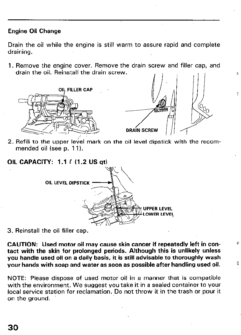
Engine Oil Change
Drain the oil while the engine is still warm to assure rapid and complete
draining.
1 i Remove the engine cover. Remove the drain screw and filler cap, and
drain the oil. Reinstall the drain screw.
OIL FILLER CAP
/
DRAIN SCREW
,
2. Refill to the upper level mark on the oil level dipstick with the recom-
mended oil (see p. 11).
OIL CAPACITY: 1.1 P (I .2 US qt)
OIL LEVEL DIPSTICK
UPPER LEVEL
LOWER LEVEL
3. Reinstall the oil filler cap.
CAUTION: Used motor oil may cause skin cancer if repeatedly left in con- *
tact with the skin for prolonged periods. Although this is unlikely unless
you handle used oil on a daily basis, it is still advisable to thoroughly wash
your hands with soap and water as soon as possible after handling used oil.
%
NOTE: Please dispose of used motor oil in a manner that is compatible
with the environment. We suggest you take ,it in a sealed container to your
local service station for reclamation. Do not throw it in the trash or pour it
on the ground.
30
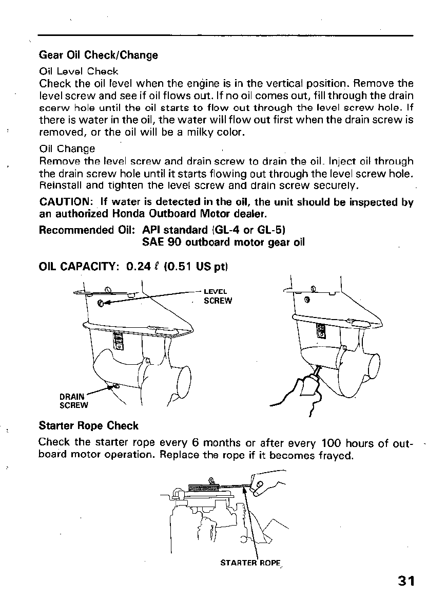
Gear Oil Check/Change
Oil Level Check
Check the oil level when the engine is in the vertical position. Remove the
level screw and see if oil flows out. If no oil comes out, fill through the drain
scerw hole until the oil starts to flow out through the level screw hole. If
there is water in the oil, the water will flow out first when the drain screw is
removed, or the oil will be a milky color.
Oil Change
Remove the level screw and drain screw to drain the oil. Inject oil through
the drain screw hole until it starts flowing out through the level screw hole.
Reinstall and tighten the level screw and drain screw securely.
CAUTION: If water is detected in the oil, the unit should be inspected by
an authorized Honda Outboard Motor dealer.
Recommended Oil: API standard (GL-4 or GL-5)
SAE 90 outboard motor gear oil
OIL CAPACITY: 0.24 e (0.51 US pt)
Starter Rope Check
Check the starter rope
board motor operation. every 6 months or after every 100 hours of out-
-
Replace the rope if it becomes frayed.
STARTER ROPE
31
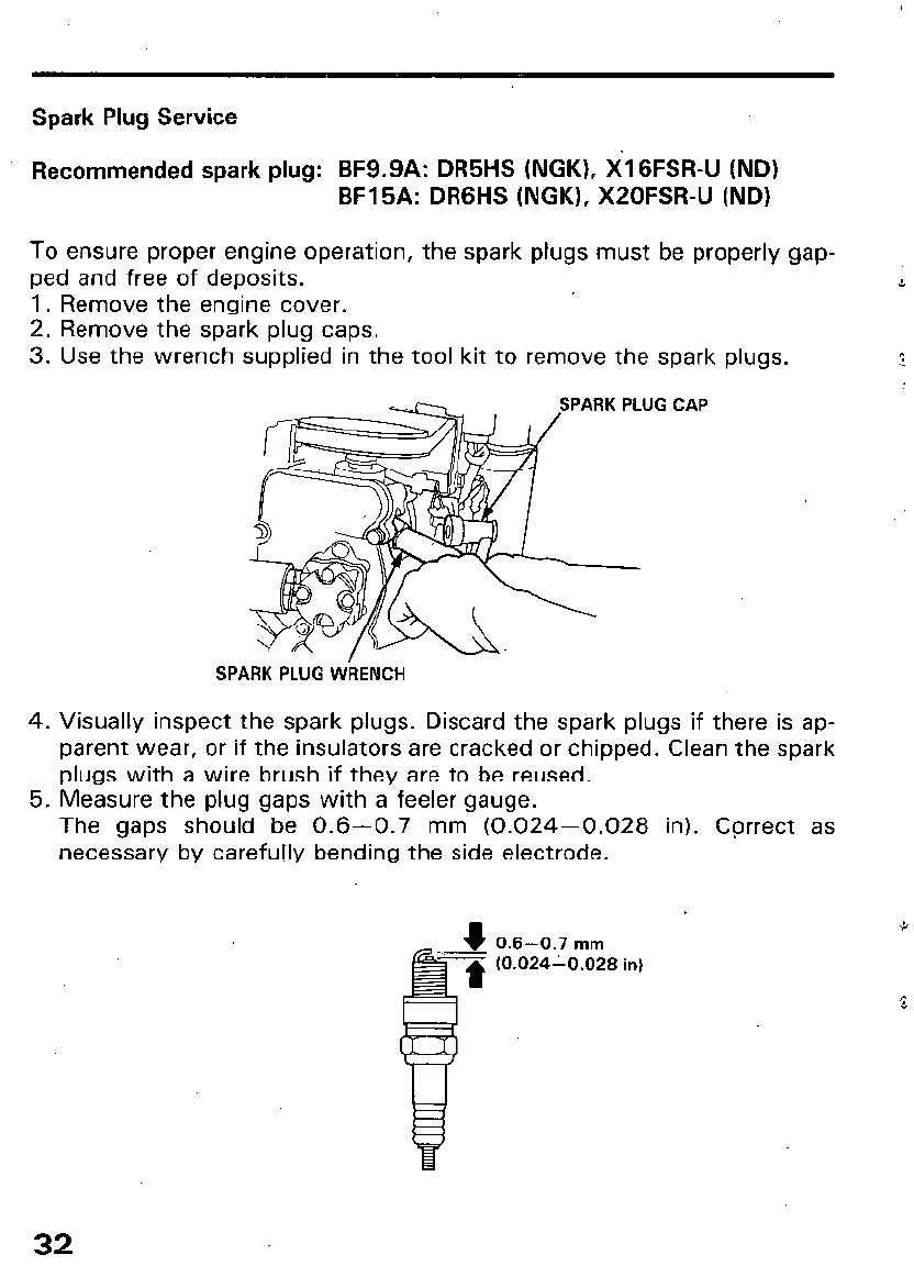
Spark Plug Service
Recommended spark plug: BF9.9A: DR5HS (NGK), XIGFSR-U (ND)
BF15A: DRGHS (NGK), XZOFSR-U (ND)
To ensure proper engine operation, the spark plugs must be properly gap-
ped and free of deposits.
1. Remove the engine cover.
2. Remove the spark plug caps.
3. Use the wrench supplied in the tool kit to remove the spark plugs.
PLUG CAP
-
SPARK PLUG WkENCH
4. Visually inspect the spark plugs. Discard the spark plugs if there is ap-
parent wear, or if the insulators are cracked or chipped. Clean the spark
plugs with a wire brush if they are to be reused.
5. Measure the plug gaps with a feeler gauge.
The gaps should be 0.6-0.7 mm (0.024-0.028 in). Correct as
necessary by carefully bending the side electrode.
0.6-0.7 mm
(0.02410.028 in)
32
6. Thread the plugs in by hand to prevent cross threading.
7. After the spark plugs are seated, tighten with a spark plug wrench to
compress the washers.
NOTE: If installing new spark plugs, tighten l/2 turn after the spark plugs
seat to compress the washers. If reinstalling used spark plugs, tighten
l/8- l/4 turn after the spark plugs seat to compress the washers.
CAUTION:
l
The spark plugs must be securely tightened. Improperly tightened plug
can become very hot and may cause engine damage.
l
Use only the recommended spark plugs or equivalent. Spark plugs
which have an improper heat range may cause engine damage.
33
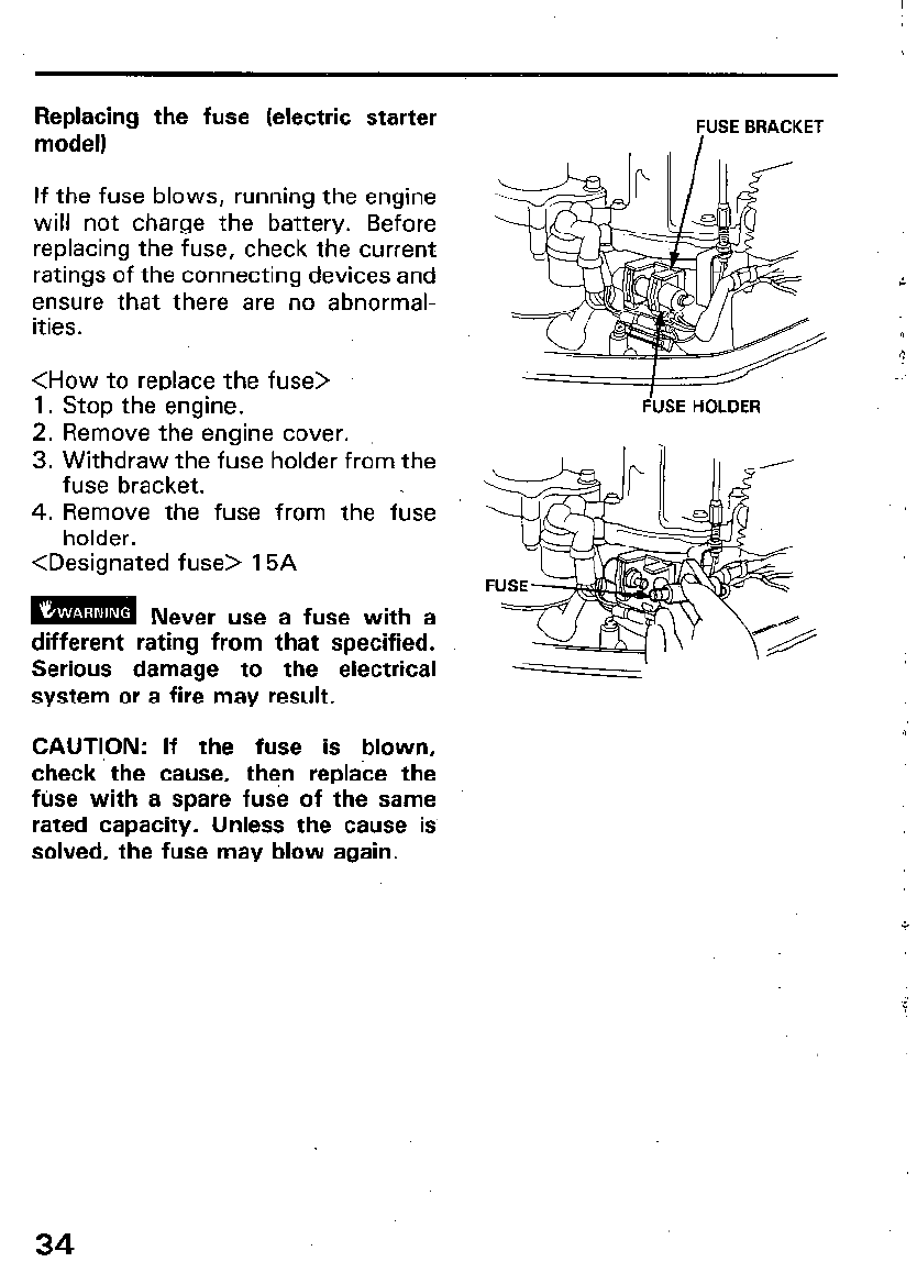
Replacing the fuse (electric starter
model)
If the fuse blows, running the engine
will not charge the battery. Before
replacing the fuse, check the current
ratings of the connecting devices and
ensure that there are no abnormal-
ities.
<How to replace the fuse>
1. Stop the engine.
2. Remove the engine cover.
3. Withdraw the fuse holder from the
fuse bracket.
4. Remove the fuse from the fuse
holder.
<Designated fuse> 15A
raml
Never use a fuse with a
different rating from that specified.
Serious damage to the electrical
system or a fire may result.
CAUTl,ON: If the fuse is blown,
check the cause, then replace the
fuse with a spare fuse of the same
rated capacity. Unless the cause is
solved, the fuse may blow again.
IfUSE BRACKET
FbSE HOLDER
34
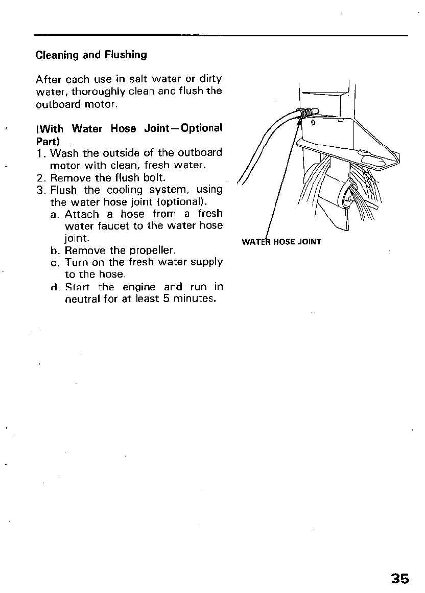
Cleaning and Flushing
After each use in salt water or dirty
water, thoroughly clean and flush the
outboard motor.
(With Water Hose Joint-Optional
Part)
1. Wash the outside of the outboard
motor with clean, fresh water.
2. Remove the flush bolt.
3. Flush the cooling system, using
the water hose joint (optional).
a. Attach a hose from a fresh
water faucet to the water hose
joint.
b. Remove the propeller.
c. Turn on the fresh water supply
to the hose.
d. Start the engine and run in
neutral for at least 5 minutes.
35
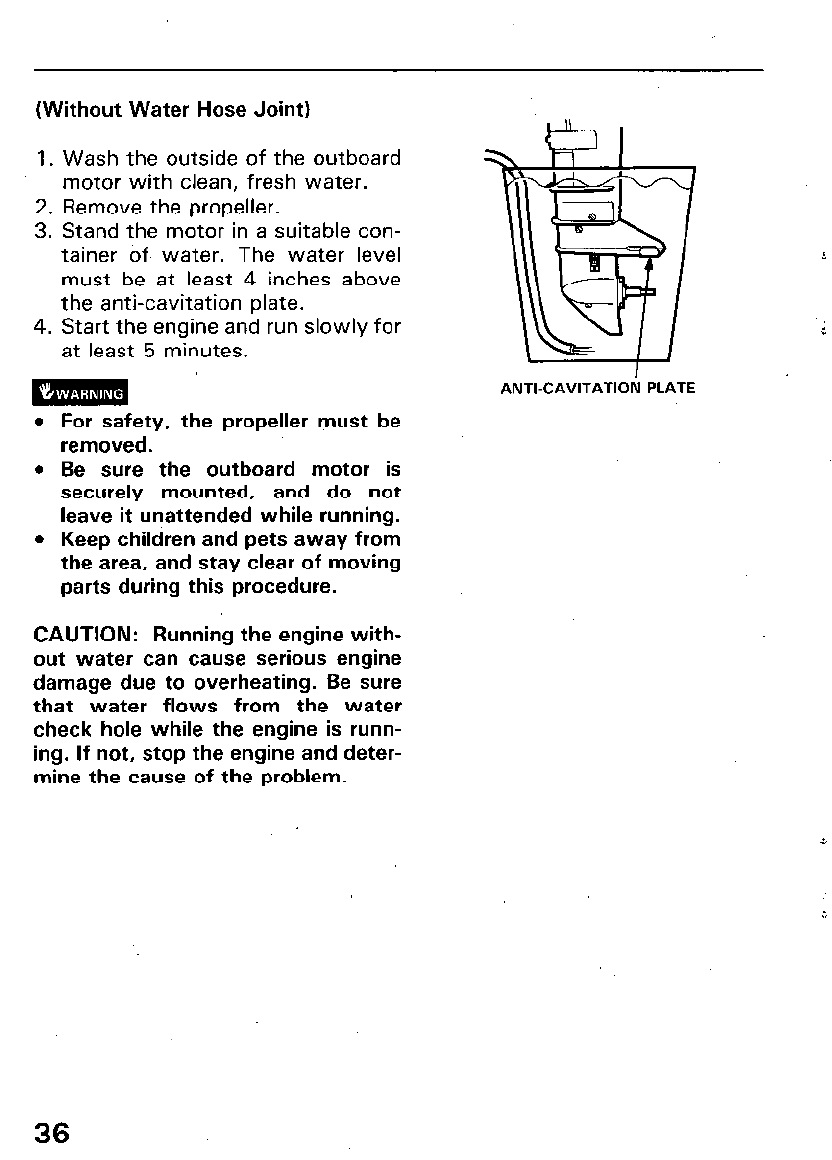
(Without Water Hose Joint)
1.
2.
3.
4.
Wash the outside of the outboard
motor with clean, fresh water.
Remove the propeller.
Stand the motor in a suitable con-
tainer Of water. The water level
must be at least 4 inches above
the anti-cavitation plate.
Start the engine and run slowly for
at least 5 minutes.
m ’
ANTI-CAVITATIOI: PLATE
l
For safety, the propeller must be
removed.
l
Be sure the outboard motor is
securely mounted, and do not
leave it unattended while running.
l
Keep children and pets away from
the area, and stay clear of moving
parts during this procedure.
CAUTION: Running the engine with-
out water can cause serious engine
damage due to overheating. Be sure
that water flows from the water
check hole while the engine is runn-
ing. If not, stop the engine and deter-
mine the cause of the problem.
36
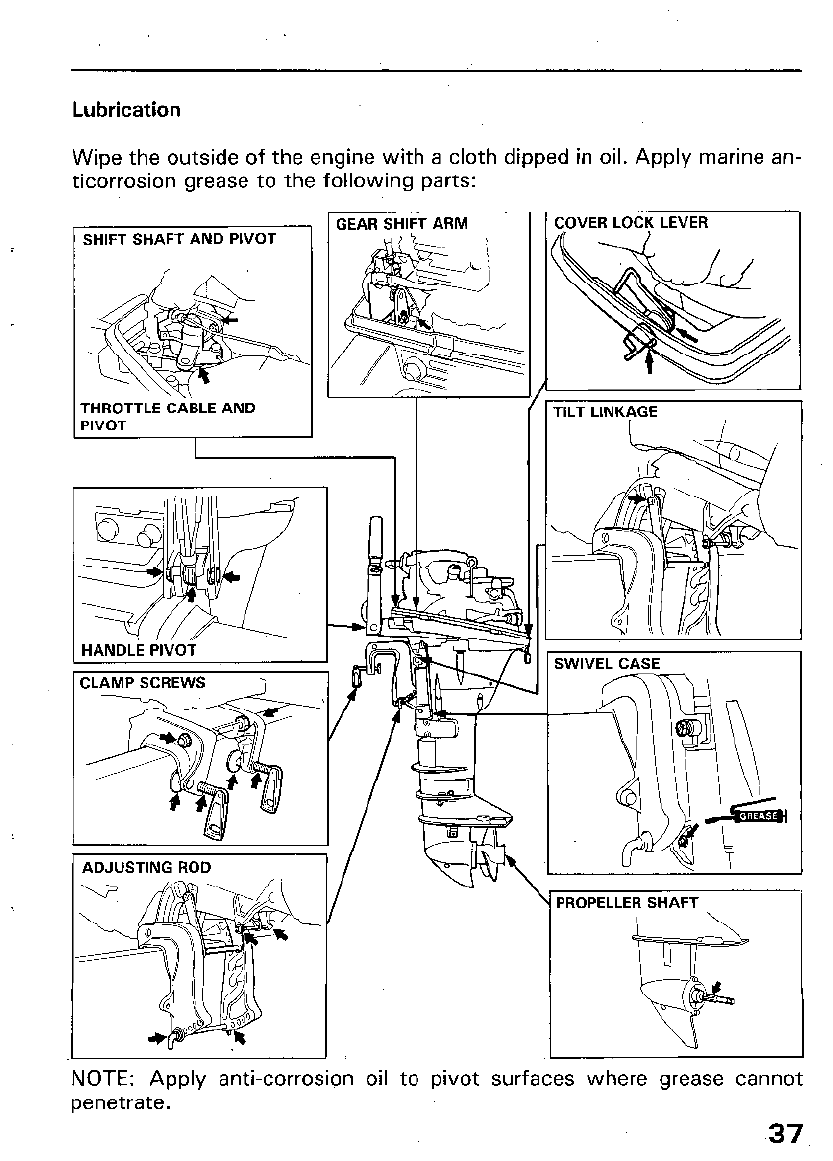
Lubrication
Wipe the outside of the engine with a cloth dipped in oil. Apply marine an-
ticorrosion grease to the following parts:
SHIFT SHAFT AND PIVOT
;;tO$TLE CA:,. AND 1
GEAR SHIFT ARM
ADJUSTING ROD
I
\
PROPELLER SHAFT I
:OVER LOCK LEVER
rlLT LINKAGE
NOTE: Apply anti-corrosion oil to pivot surfaces where grease cannot
penetrate.
37
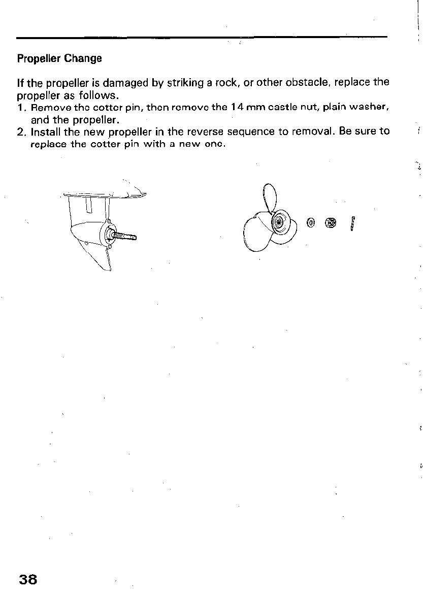
Propeller Change
If the propeller is damaged by striking a rock, or other obstacle, replace the
propeller as follows.
1. Remove the cotter pin, then remove the 14 mm castle nut, plain washer,
and the propeller.
2. Install the new ,propeller in the reverse sequence to removal. Be sure to
replace the cotter pin with a new one. ‘i
38
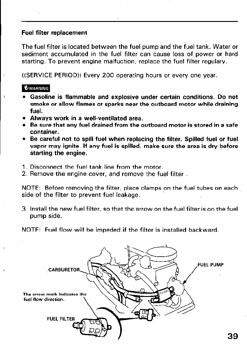
Fuel filter replacement
The fuel filter is located between the fuel pump and the fuel tank. Water or
sediment accumulated in the fuel filter can cause loss of power or hard
starting. To prevent engine malfuction, replace the fuel filter regulary.
((SERVICE PERIOD)) Every 200 operating hours or every one year.
l
Gasoline is flammable and explosive under certain conditions. Do not
smoke or allow flames or sparks near the outboard motor while draining
fuel.
l
Always work in a well-ventilated area.
l
Be sure that any fuel drained from the outboard motor is stored in a safe
container.
l
Be careful not to spill fuel when replacing the filter. Spilled fuel or fuel
vapor may ignite. If any fuel is spilled, make sure the area is dry before
starting the engine.
1. Disconnect the fuel tank line from the motor.
2. Remove the engine cover, and remove the fuel filter .
NOTE: Before removing the filter, place clamps on the fuel tubes on each
side of the filter to prevent fuel leakage.
3. Install the new fuel filter, so that the arrow on the fuel filter is on the fuel
pump side.
NOTE: Fuel flow will be impeded if the filter is installed backward.
.CARBURETOR
The arrow mark indicates t
fuel flow direction.
FUEL FILTE
,FUEL
39
4. Remove the clamps used to close the fuel tubes. Connect the fuel tank
line to the motor. Turn the fuel tank vent knob to the ON position, pump
the primer bulb, and check for leaks.
NOTE: If loss of power or hard starting is found to be caused by excessive
water or sediment accumulated in the fuel filter, inspect the fuel tank.
Clean the fuel tank if necessary.
40
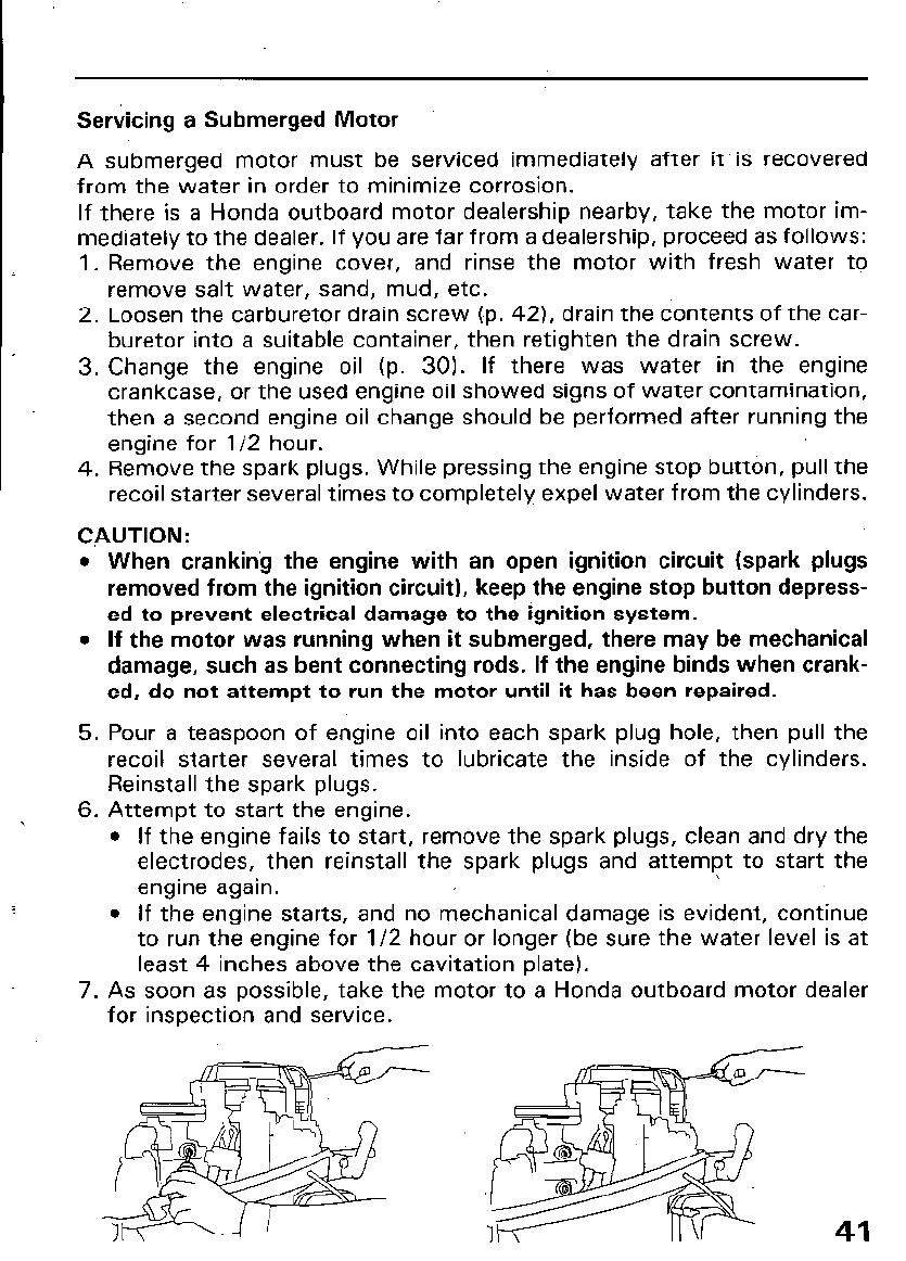
Servicing a Submerged Motor
A submerged motor must be serviced immediately after it. is recovered
from the water in order to minimize corrosion.
If there is a Honda outboard motor dealership nearby, take the motor im-
mediately to the dealer. If you are far from a dealership, proceed as follows:
1. Remove the engine cover, and rinse the motor with fresh water to
remove salt water, sand, mud, etc.
2. Loosen the carburetor drain screw (p. 421, drain the contents of the car-
buretor into a suitable container, then retighten the drain screw.
3. Change the engine oil (p. 30). If there was water in the engine
crankcase, or the used engine oil showed signs of water contamination,
then a second engine oil change should be performed after running the
engine for l/2 hour.
4. Remove the spark plugs. While pressing the engine stop button, pull the
recoil starter several times to completely expel water from the cylinders.
CAUTION:
l
When cranking the engine with an open ignition circuit (spark plugs
removed from the ignition circuit), keep the engine stop button depress-
ed to prevent electrical damage to the ignition system.
l
If the motor was running when it submerged, there may be mechanical
damage, such as bent connecting rods. If the engine binds when crank-
ed, do not attempt to run the motor until it has been repaired.
5. Pour a teaspoon of engine oil into each spark plug hole, then pull the
recoil starter several times to lubricate the inside of the cylinders.
Reinstall the spark plugs.
6. Attempt to start the engine.
l
If the engine fails to start, remove the spark plugs, clean and dry the
electrodes, then reinstall the spark plugs and attempt to start the
engine again.
l
If the engine starts, and no mechanical damage is evident, continue
to run the engine for l/2 hour or longer (be sure the water level is at
least 4 inches above the cavitation plate).
7. As soon as possible, take the motor to a Honda outboard motor dealer
for inspection and service.
41
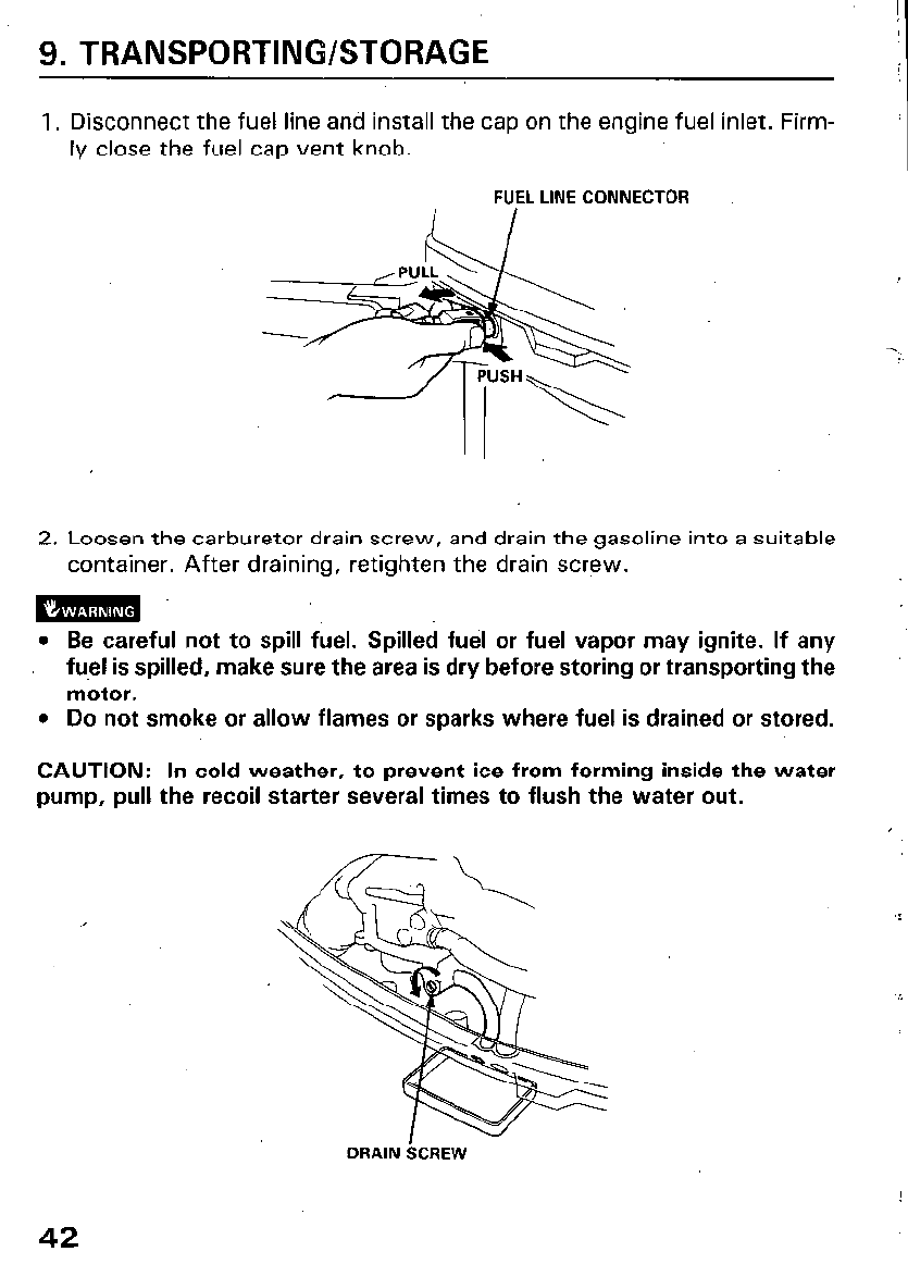
9. TRANSPORTING/STORAGE
1. Disconnect the fuel line and install the cap on the engine fuel inlet. Firm-
ly close the fuel cap vent knob.
FUEL LINE CONNECTOR
2. Loosen the carburetor drain screw, and drain the gasoline into a suitable
container. After draining, retighten the drain screw.
l Be careful not to spill fuel. Spilled fuel or fuel vapor may ignite. If any
fuel is spilled, make sure the area is dry before storing or transporting the
motor.
. Do not smoke or allow flames or sparks where fuel is drained or stored.
CAUTION: In cold weather, to prevent ice from forming inside the water
pump, pull the recoil starter several times to flush the water out.
DRAIN iXREW
42
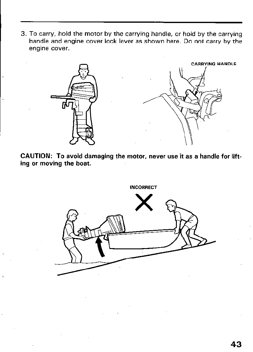
3. To carry, hold the motor by the carrying handle, or hold by the carrying
handle and engine cover lock lever as shown here. Do not carry by the
engine cover.
CAUTION: To avoid damaging the motor, never use it as a handle for lift-
ing or moving the boat.
INCORRECT
43
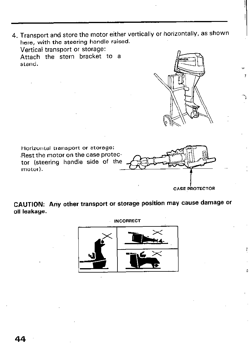
4. Transport and store the motor either vertically or horizontally, as shown
here, with the steering handle raised.
Vertical transport or storage:
Attach the stern bracket to a
stand.
Horizontal transport or storage:
.Rest the motor on the case protec-
tor (steering handle side of th
motor).
CASE PROTECTOR
CAUTION: Ariy other transport or storage position may cause damage or
oil leakage.
INCORRECT
6
44
5. Tilt up the outboard motor, remove the plug cap, pull the recoil starter
several times, and completely drain off the cooling water.
CAUTION: If the outboard motor is put on its side without completely
draining off the cooling water immediately after stopping it, water may
enter the engine from the exhaust port. Be sure, therefore, to drain off the
cooling water before putting the outboard motor on its side.
When pulling the starting grip, be careful not to touch the spark plug wire.
6. Pull the starting grip until resistance is felt (i.e. until the engine valve
closes, preventing dust from entering the combustion chamber).
7. Store the outboard motor in a clean, dry area.
NOTE: Before storing, clean, flush! and lubricate the outboard motor as
described on pages 35 and 37.
45
IO. TROUBLESHOOTPNG
Engine’ Will Not Start:
:I
1. Is the shift lever in neutral?
2. Is there fuel in the fuel tank?
3. Is the fuel cap knob turned to ON?
4. Is the fuel system primed by squeezing the primer bulb? Y
5. Is fuel reaching the carburetor?
Loosen the carburetor drain screw to see if there is fuel in the carburetor
float bowl.
-‘i
mEm
If any fuel is spilled, make sure the area is dry before testing the
spark plug or starting the engine. Spilled fuel or fuel vapor may ignite.
6. Are the spark plugs firing?
Method of detecting spark
(1) Remove the spark plugs from the engine, then install each plug in the
plug cap and hold the threaded portion against the engine to ground it.
(2) Recoil starter type
Put the gear lever in the “NEUTRAL” position, pull the starter grip
hard; and check to see whether or not a spark appears across the gap
of the spark plug.
Starter motor type
Put the gear lever in the “NEUTRAL” position, rotate the starter motor,
and check to see whether or not a spark appears across the gap of the
spark plug.
If the spark plugs are OK, reinstall them, and try to start the engine.
If a spark does not appear, either replace the spark plug or contact your
authorized Honda outboard motor dealer.
Engine Overheats:
1. Is the water intake screen clogged?
2. Is the thermostat faulty?
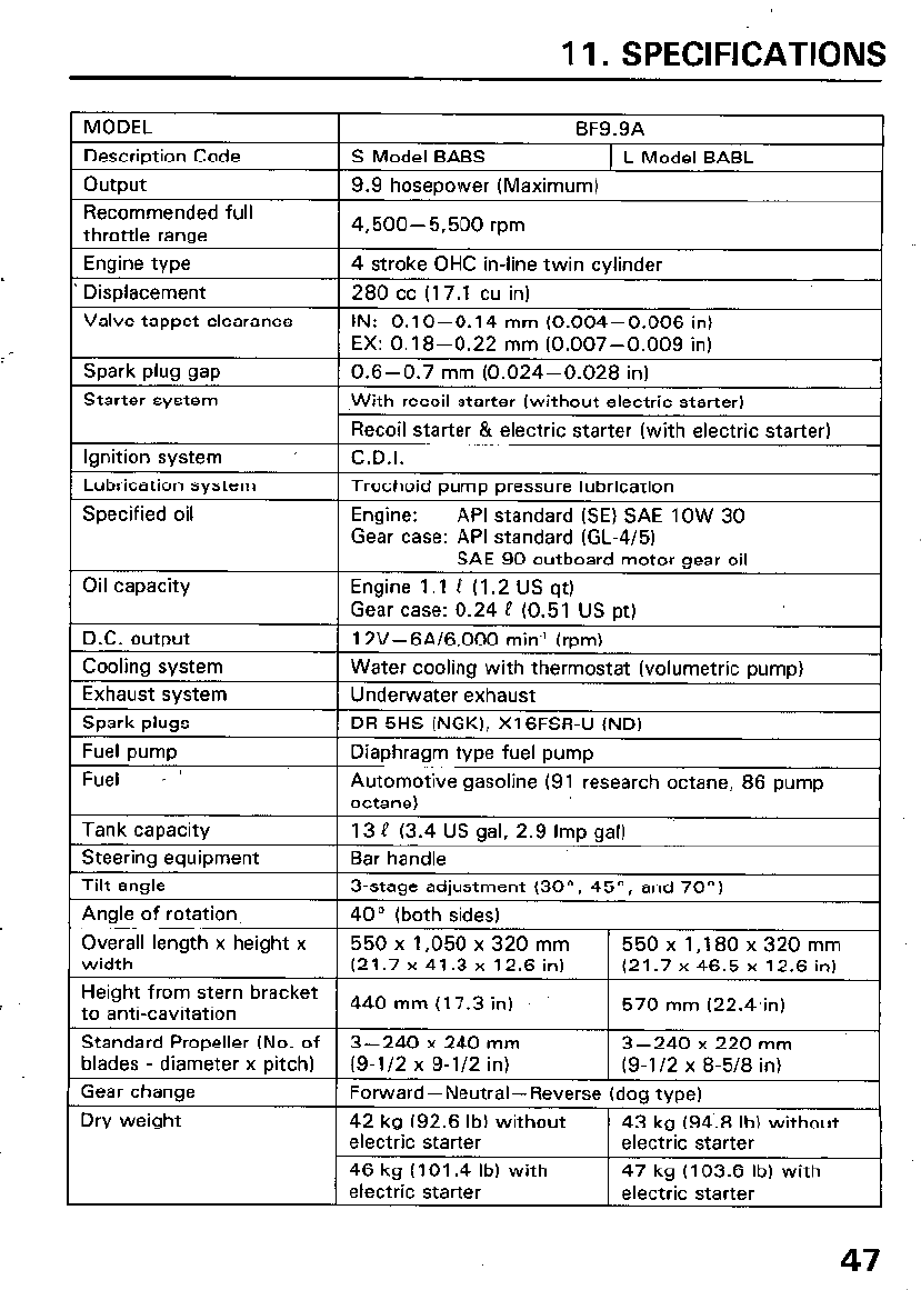
11. SPECIFICATIONS
MODEL
Description Code
output
BF9.9A
S Model BABS 1 L Model BABL
9.9 hosepower (Maximum)
Recommended full
throttle range
Engine type
Displacement
Valve tappet clearance
4,500-5,500 rpm
1
4 stroke OHC in-line twin cylinder
280 cc (17.1 cu in)
IN: 0.1 O-O.14 mm (0.004-0.006 in)
EX: 0.18-0.22 mm (0.007-0.009 in)
Spark plug gap 0.6-0.7 mm (0.024-0.028 in)
Starter system 1 With recoil starter (without electric starter)
Gear case: API standard (GL-4/5)
Overall length x height x 550 x 1,050 x 320 mm 550x1,180x320mm
Standard Propeller (No. of 3-240 x 240 mm
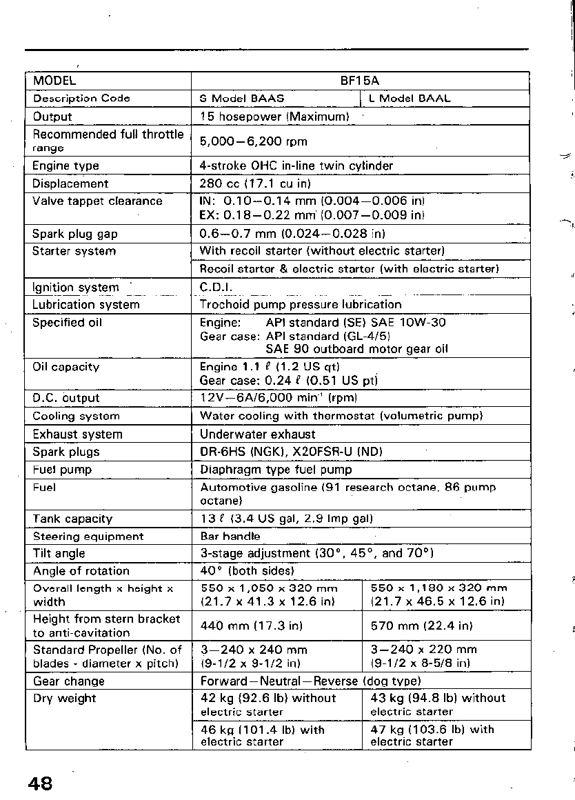
MODEL BF15A I
.-
Description Code 1 S Model BAAS 1 L Model BAAL
output 15 hosepower (Maximum)
Recommended full throttle
range
5 000-6 200 rpm
J
Enaine tvoe j 4-stroke OHC in-line twin cvlinder
Displacement 1 280 cc (17.1 cu in) I
Valve tappet clearance IN: 0.1 O-0.14 mm (0.004-0.006 in)
EX: 0.1 B-O.22 mm’ (0.007-0.009 in) I
Spark plug gap
Starter system
( 0.6-0.7 mm (0.024-0.028 in)
.I
With recoil starter (without electric starter)
Recoil starter & electric starter (with electric starter)
1 C.D.I.
I
Ignition system
Lubrication system
Specified oil
Trochoid pump pressure lubrication
Engine: API standard (SE) SAE low-30
Gear case: API standard (GL-4/5)
SAE 90 outboard motor aear oil
Oil capacity Engine 1 .I P (1.2 US qt)
Gear case: 0.24 P (0.51 US pti
D.C. output I 12V-6A/6,000 min.’ (rpm)
Cooling system
Exhaust system
Spark pluas
Water cooling with thermostat (volumetric pump)
Underwater exhaust
DR-6HS (NGK). X20FSRU (ND)
Fuel pump 1 Diaphraqm type fuel pump
Fuel
Tank caoacitv
Automotive gasoline (91 research octane, 86 pump
octane)
13 P (3.4 US aal. 2.9 Imo aal)
Steerina eauipment 1 Bar handle
-
Tilt angle
Anole of rotation
3-stage adjustment (30”, 45’, and 70”)
40” (both sides)
Overall length x height x 550 x 1,050 x 320 mm 550xl,180x320mm
width (21.7 x 41.3 x 12.6 in) (21.7 x 46.5 x 12.6 in)
Height from stern bracket
to anti-cavitation 440 mm (I 7.3 in) 570 mm (22.4 in)
Standard Propeller (No. of 3-240 x 240 mm 3-240 x 220 mm
blades - diameter x pitch) (9-l/2 x 9-l/2 in) (9-l/2 x 8-5/8 in) I
Gear change
Dry weight
Forward-Neutral-Reverse (dog type)
42 kg (92.6 lb) without 43 kg (94.8 lb) without
electric starter electric starter
46 kg (I 01.4 lb) with
electric starter 47 kg (103.6 lb) with
electric starter
48
I 79
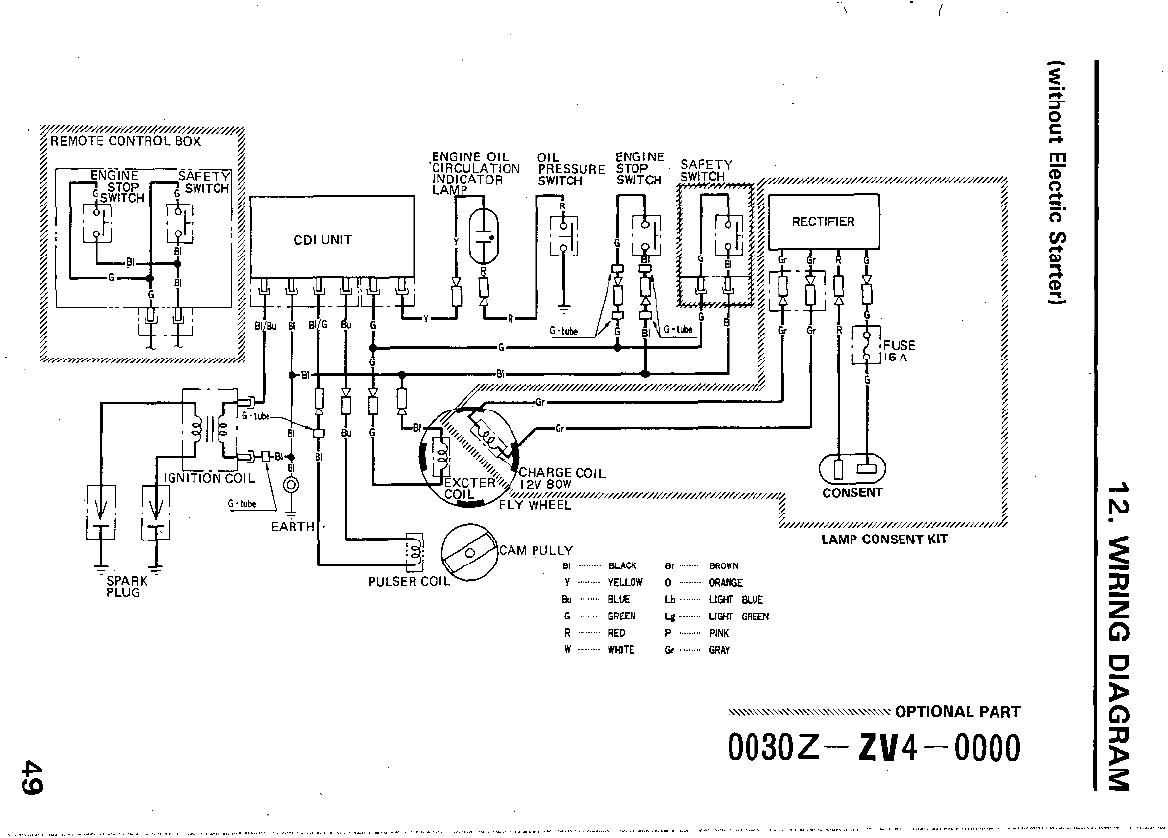
&REMOTE CONTROL BOX 4
- -
H. 1
1
--!j @jCAM PULLY
-w
PULSER COIL
8, ........ ua( 8, ......... BROWN
y ......... “EUOy/ 0 ........ ORANGE
& ......... BL”E Lb ......... UGHT BLUE
G ......... GREEN Lg ......... UGHT GREEN
R ......... RED p ........ p,NK
w ......... W",TE Gr ........ GRA"
~,,,,,,,,,//,N///////////////////////
LAMP CONSENT KIT
~\\\\\\\\\\\\\\\,,,,,,,,,,~ OPTI 0 NAL PART
003oz- zv4- 0000
ul
0
~~,,~,,,,,,,,,,~,~,,,,~~
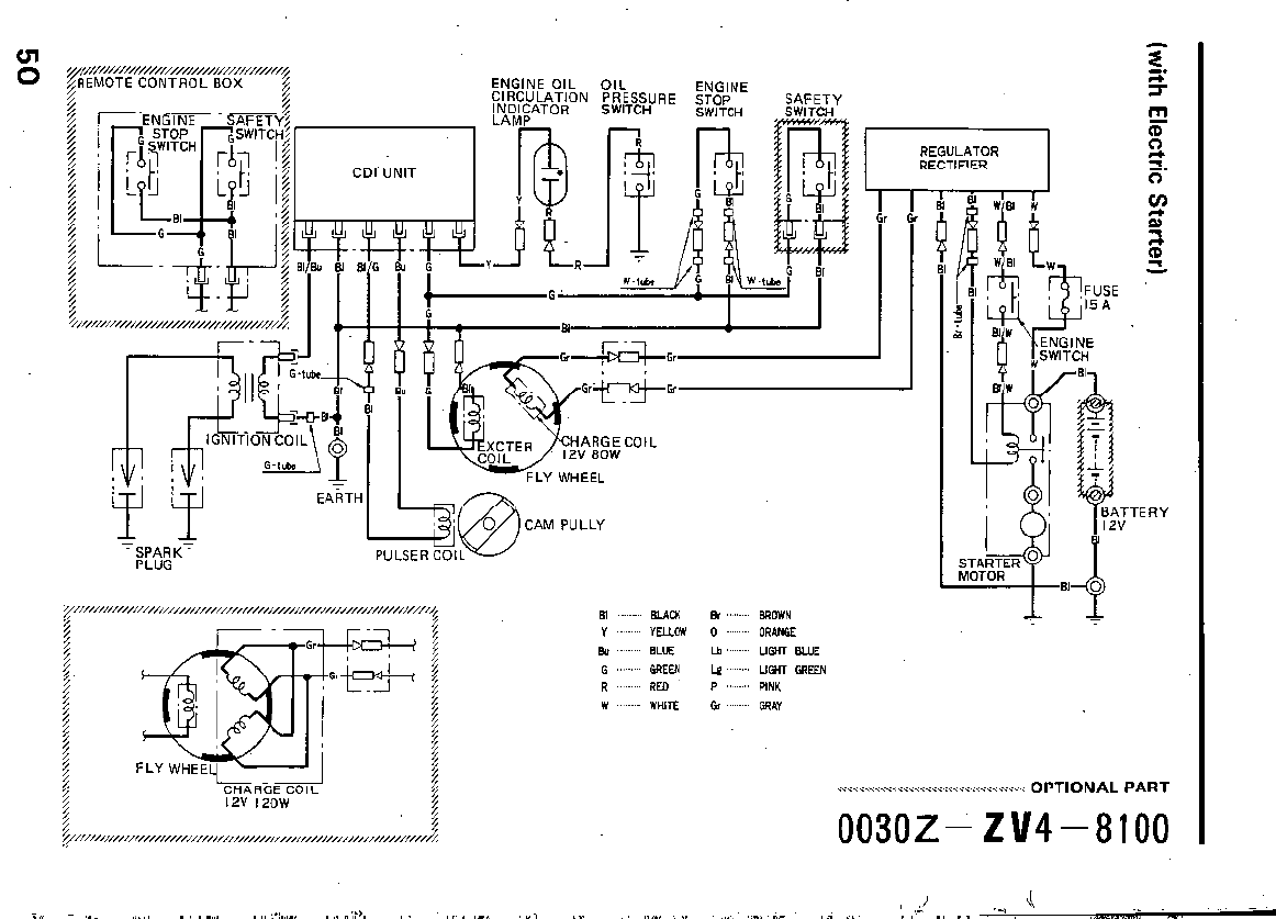
/REMOTE CONTROL BOX
g
+
6
CDI UNIT
ENGINE OIL
CIRCULATION
k;DJ$ATOR
OIL
PRESSURE
SWITCH
ENGINE
STOP
SWITCH
-FLY WHEEL
CAM PULLY
L
~NN///N///N///////,,,,,,,,,,,,,,,,,,,,,,,,,,,,,,,,,,,,,,,,,,,
5
t
P
5
9
L-
G
t
5
5
t
5
5
6
5
G
5
t
12v
IZOW
5
5
~,,,,,,,,,,,,,,,,,,,,,,,,,,,,,,,,,,,,,,,,,,,,,,,,,,,,,,,,,,,,,,,,,,,~
8, ......... ml-J 0, ......... W(JWN
y ......... yug)w 0 ......... ORANGE
b ......... B’JJE Lb ......... UGHT BLUE
G ........ &r&g
U ........ LIGHT GREEN
R ........ RED p ......... P,p.jK
w ......... w’.“x G, ......... GRI\‘,
.\\\\\\\\\\\\\\\\\\\\\\\\\\\\\\\\\\ 0 PTI 0 N AL PART
003OZ-
ZV4-8100
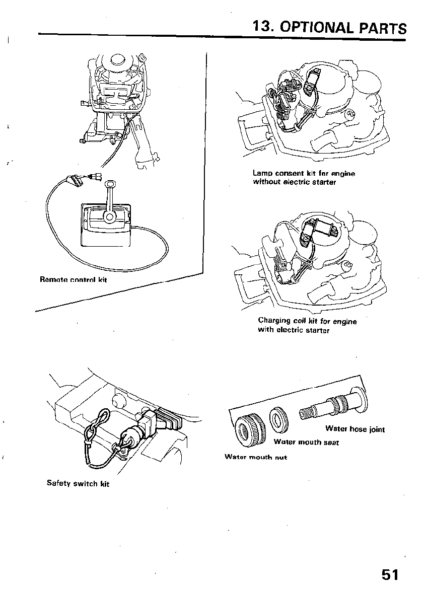
13. OPTIONAL PARTS
Lamp consent kit for engine
without electric starter
Charging coil kit for engine
with electric starter
Water mouth nut
Water hose joint
mouth seat
Safety switch kit
51
14. WARRANTY SlEWVICE
Owner Satisfaction
Your satisfaction and goodwill are important to your dealer and to us. All
Honda warranty details are explained in the Distributor’s Limited Warranty.
Normally, any problems concerning the product will be handled by your
dealer’s service department. If you have a warranty problem that has not +
been handled to your satisfaction, we suggest you take the following
5
action:
l Discuss your problem with a member of dealership management. Often
-7
complaints can be quickly resolved at that level. If the problem has
already been reviewed with the Service Manager, contact the owner of
the dealership or the General Manager.
l If your problem still has not been resolved to your satisfaction, contact
the Power Equipment Customer Relations Department of American
Honda Motor Co., Inc.
American Honda Motor Co., Inc.
Power Equipment Customer Relations Department
P.O. Box 50
Gardena, California 90247-0805
Telephone: (2 13) 604-2400
We will need the following information in order to assist you:
- Your name, address, and telephone number
- Product model and serial number
- Date of purchase
- Dealer name and address
- Nature of the problem
After reviewing all the facts involved, you will be advised of what action
can be taken. Please bear in mind that your problem will likely be resolved
at the dealership, using the dealer’s facilities, equipment, and personnel, so
it is very important that your initial contact be with the dealer.
Your purchase of a Honda product is greatly appreciated by both your
dealer and American Honda Motor Co., Inc. We want to assist you in every
way possible to assure your complete satisfaction with your purchase.
52
Current customer service contact information:
Your owner's manual was written to cover most of the questions you might ask about
your Honda. Any questions not answered in the owner's manual can be answered by
your Honda dealer. If your dealer doesn't have an immediate answer, they should be
able to get it for you.
If you have a difference of opinion with your dealer, please remember that each
dealership is independently owned and operated. That's why it's important to work to
resolve any differences at the dealership level. If the service personnel are unable to
assist you, please discuss your concerns with the dealer management such as the
Service Manager or the dealership's owner.
If you need to contact American Honda regarding your experiences with your Honda
product or with your dealer, please send your comments to the following address:
American Honda Motor Co., Inc.
Marine Division
Customer Relations Office
4900 Marconi Drive
Alpharetta, GA 30005-8847
Or telephone: (770) 497-6400 M-F, 8:30 am - 7:00 pm EST
When you write or call, please provide the following information:
• Your name, address and telephone number (complete with area code)
• Model and complete serial number
• Date of purchase
• Name and location of the selling dealer
• Name and location of the servicing dealer (if different)
• A detailed description of your concerns

Owner's Manual
Outboard Motor
BFg.yA/15A
I I I I I I I I I I I I I I I I I I I I I
<SUPPLEMENT>
@ 1993 American Honda Motor Co., Inc. - All Rights Reserved
I
I
I
I
I
I
I
I
I
I
I
I
I

Thank you for purchasing a Honda Outboard Motor.
This owners manual supplement covers specific information about the Honda
remote control equipped BF9.9A and BF15A outboard motors. Refer to the
BF9.9A/15A owner’s manual for all other information.
The owner’s manual and this supplement contain information on how to operate
your new outboard motor safely. Please read them carefully.
Keep the owners manual and this supplement handy, so you can refer to them
at any time, and be sure they accompany the outboard motor if you sell it.
We recommend that you read the warranty policy to fully understand your rights
and responsibilities. The warranty policy is a separate document provided by
your dealer.
The information in this publication was in effect at the time of approval for
printing. American Honda Motor Co., Inc. reserves the right to discontinue or
change specifications or design at any time without notice and without incurring
any obligation whatever. No part of this publication may be reproduced without
written permission.
01993 American Honda Motor Co., Inc. - All Rights Reserved
1
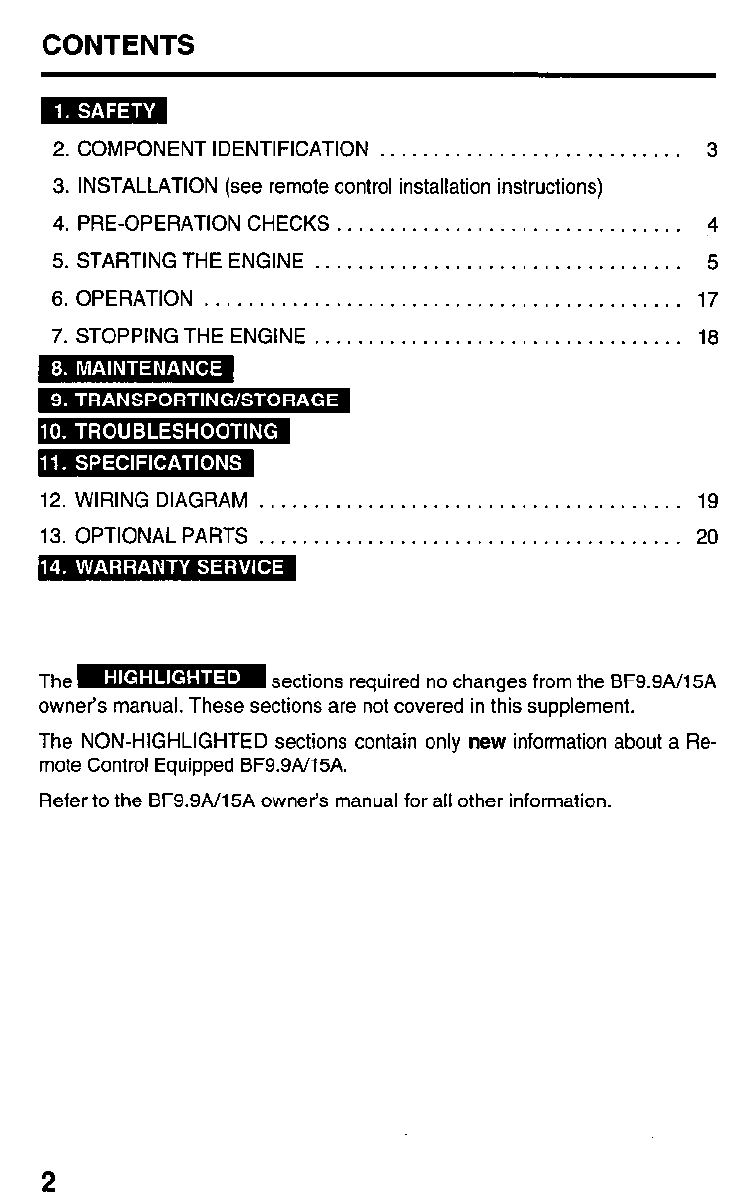
CONTENTS
2. COMPONENT IDENTIFICATION ............................ 3
3. INSTALLATION (see remote control installation instructions)
4. PRE-OPERATION CHECKS ................................ 4
5. STARTING THE ENGINE .................................. 5
6. OPERATION ............................................ 17
7. STOPPING THE ENGINE .................................. 18
12. WIRING DIAGRAM ....................................... 19
13. OPTIONAL PARTS ....................................... 20
The- B sections required no changes from the BF9.9A/15A
owners manual. These sections are not covered in this supplement.
The NON-HIGHLIGHTED sections contain only new information about a Re-
mote Control Equipped BF9.9A/15A.
Refer to the BF9.9A/15A owner’s manual for all other information.
2
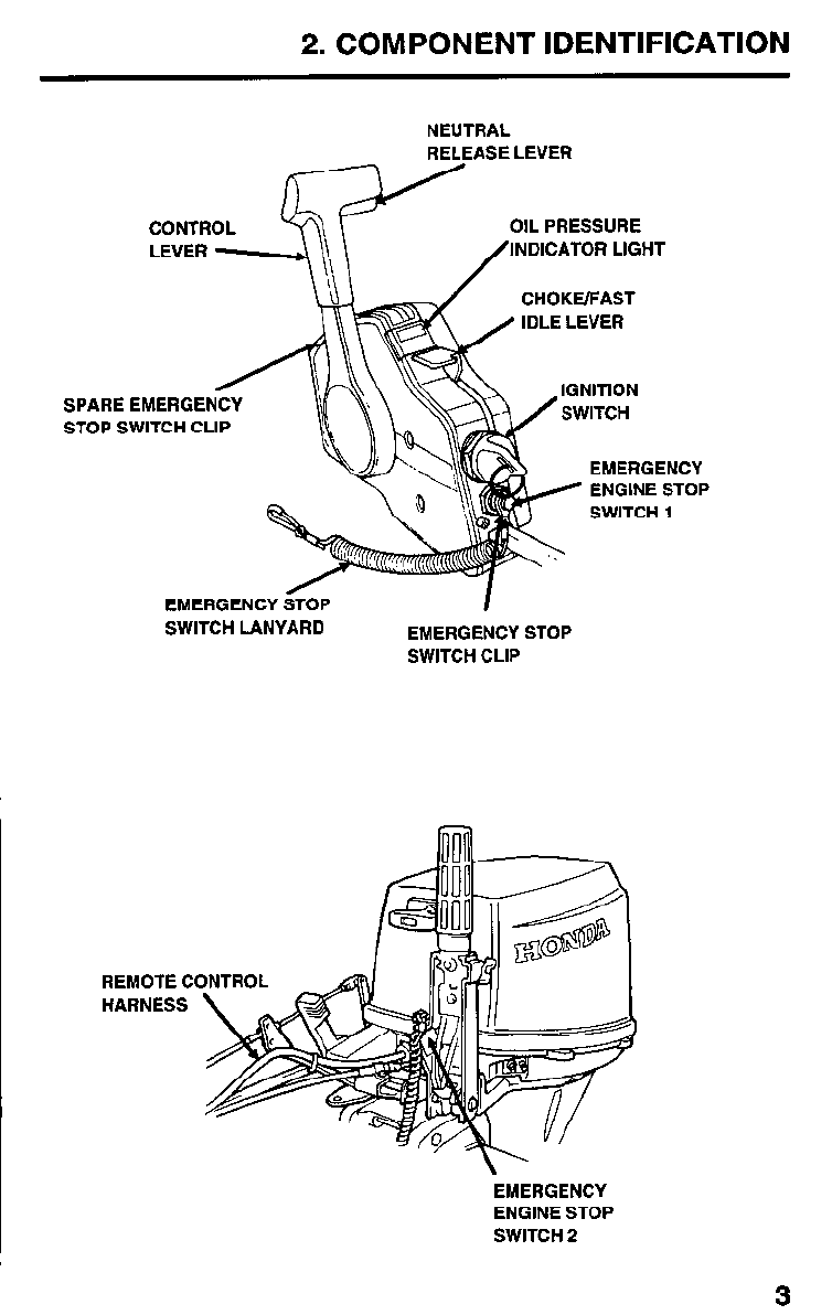
2. COMPONENT IDENTIFICATION
NEUTRAL
RELEASE LEVER
OIL PRESSURE
INDICATOR LIGHT
CHOKE/FAST
SPARE
STOP S
EMERGENCY
ENGINE STOP
EMERGENCY
SWITCH LANYARD EMERGENCY STOP
SWITCH CLIP
REMOTE C
HARNESS
EMERGENCY
ENGINE STOP
SWITCH 2
3
3. PRE-OPERATION CHECKS
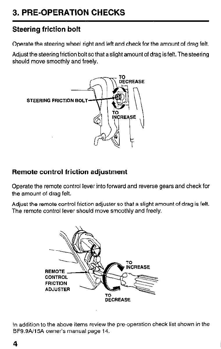
Steering friction bolt
Operate the steering wheel right and left and check for the amount of drag felt.
Adjust the steering friction bolt so that a slight amount of drag is felt. The steering
should move smoothly and freely.
STEERING FRICTION BOLT
Remote control friction adjustment
Operate the remote control lever into forward and reverse gears and check for
the amount of drag felt.
Adjust the remote control friction adjuster so that a slight amount of drag is felt.
The remote control lever should move smoothly and freely.
CONTROL
FRICTION
ADJUSTER %
DECREASE
In addition to the above items review the pre-operation check list shown in the
BF9.9N15A owner’s manual page 14.
4
5. STARTING THE ENGINE
Controls
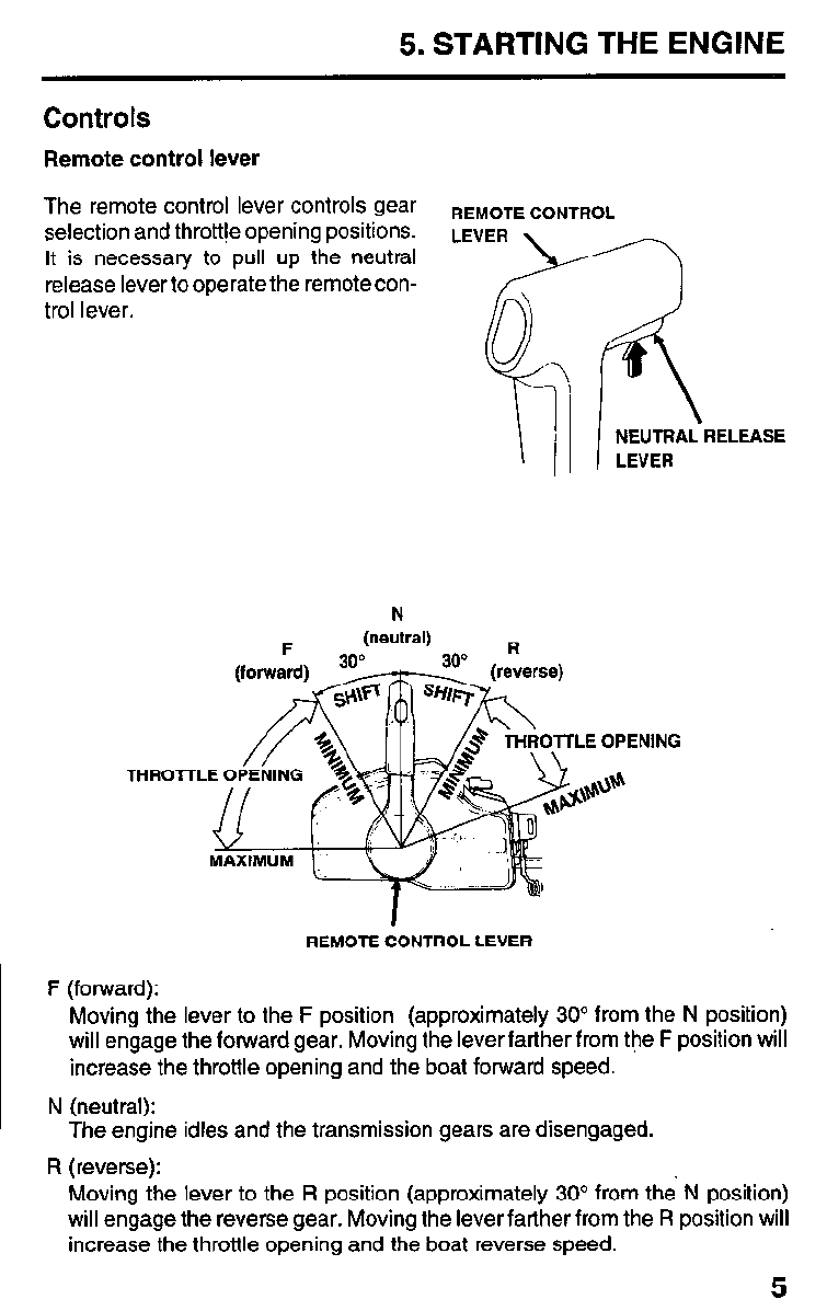
Remote control lever
The remote control lever controls gear REMOTE CONTROL
selection and throttte opening positions.
It is necessary to pull up the neutral
release lever to operate the remote con-
trol lever.
NEUTRAL RELEASE
LEVER
REMOTE CONTROL LEVER
F (forward):
Moving the lever to the F position (approximately 30” from the N position)
will engage the forward gear. Moving the lever farther from the F position will
increase the throttle opening and the boat forward speed.
N (neutral):
The engine idles and the transmission gears are disengaged.
R (reverse):
Moving the lever to the R position (approximately 30” from the N position)
will engage the reverse gear. Moving the lever farther from the R position will
increase the throttle opening and the boat reverse speed.
5
5. STARTING THE ENGINE
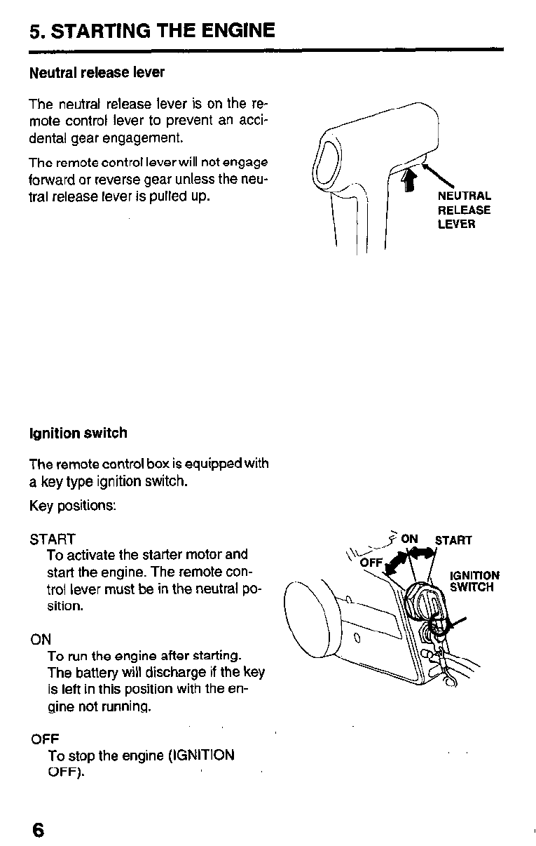
Neutral release lever
The neutral release lever is on the re-
mote control lever to prevent an acci-
dental gear engagement.
The remote control lever will not engage
forward or reverse gear unless the neu-
tral release lever is pulled up. RELEASE
LEVER
Ignition switch
The remote control box is equipped with
a key type ignition switch.
Key positions:
START
To activate the starter motor and
start the engine. The remote con-
trol lever must be in the neutral po-
sition.
ON
To run the engine after starting.
The battery will discharge if the key
is left in this position with the en-
gine not running.
OFF
To stop the engine (IGNITION
OFF).
6
5. STARTING THE ENGINE
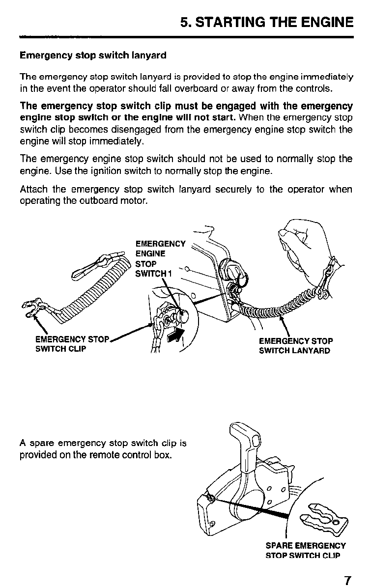
Emergency stop switch lanyard
The emergency stop switch lanyard is provided to stop the engine immediately
in the event the operator should fall overboard or away from the controls.
The emergency stop switch clip must be engaged with the emergency
engine stop switch or the engine will not start. When the emergency stop
switch clip becomes disengaged from the emergency engine stop switch the
engine will stop immediately.
The emergency engine stop switch should not be used to normally stop the
engine. Use the ignition switch to normally stop the engine.
Attach the emergency stop switch lanyard securely to the operator when
operating the outboard motor.
EMERGENCY
A spare emergency stop switch clip is
provided on the remote control box.
SPARE EMERGENCY
STOP SWITCH CLIP
5. STARTING THE ENGINE
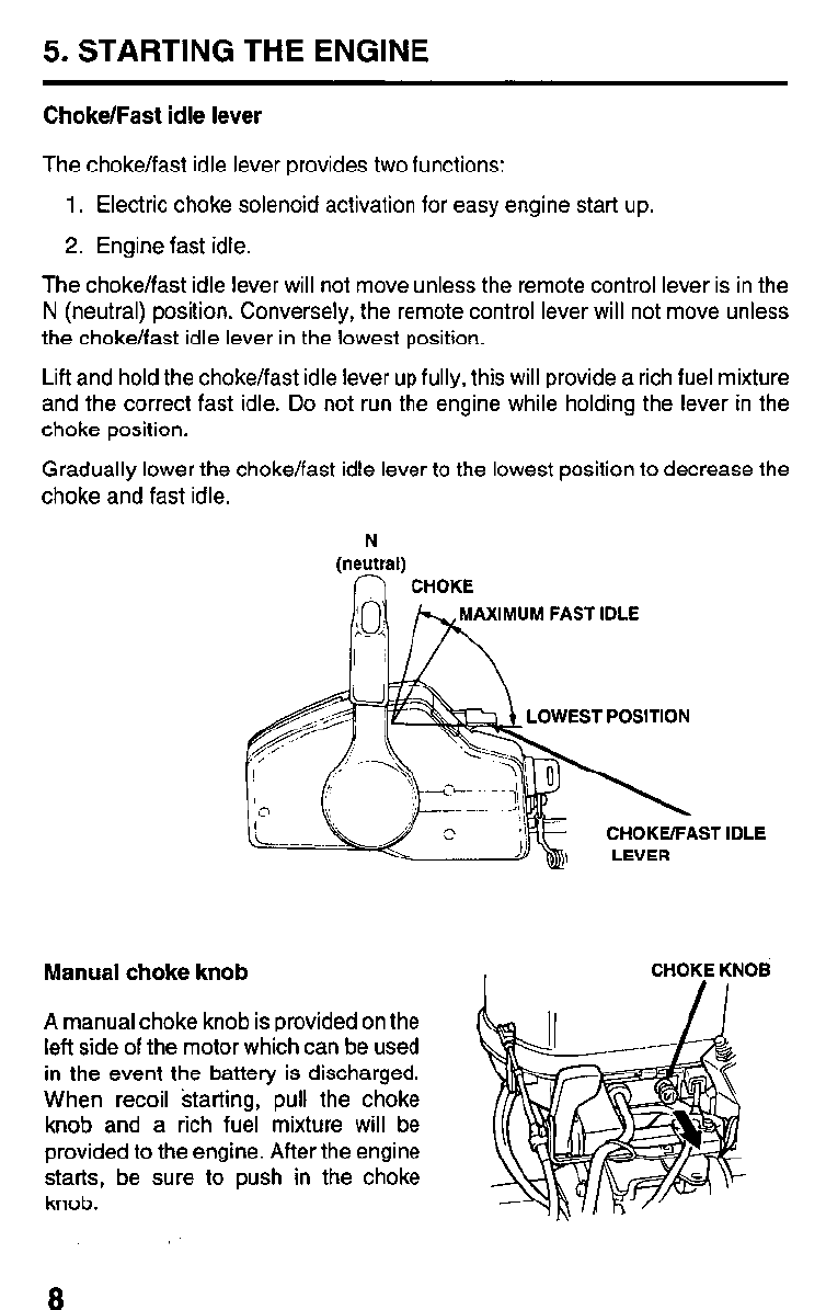
Choke/Fast idle lever
The choke/fast idle lever provides two functions:
1. Electric choke solenoid activation for easy engine start up.
2. Engine fast idle.
The choke/fast idle lever will not move unless the remote control lever is in the
N (neutral) position. Conversely, the remote control lever will not move unless
the choke/fast idle lever in the lowest position.
Lift and hold the choke/fast idle lever up fully, this will provide a rich fuel mixture
and the correct fast idle. Do not run the engine while holding the lever in the
choke position.
Gradually lower the choke/fast idle lever to the lowest position to decrease the
choke and fast idle.
N
(neutral)
n CHOKE
MAXIMUM FAST IDLE
EST POSITION
IDLE
Manual choke knob CHOKE KNOB
A manual choke knob is provided on the
left side of the motor which can be used
in the event the battery is discharged.
When recoil starting, pull the choke
knob and a rich fuel mixture will be
provided to the engine. After the engine
starts, be sure to push in the choke
knob.
R
5. STARTING THE ENGINE
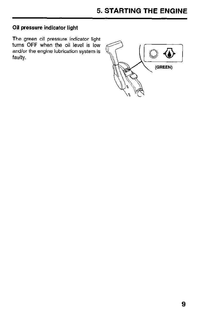
Oil pressure indicator light
The green oil pressure indicator light
turns OFF when the oil level is low
and/or the engine lubrication system is
faulty.
9
5. STARTING THE ENGINE
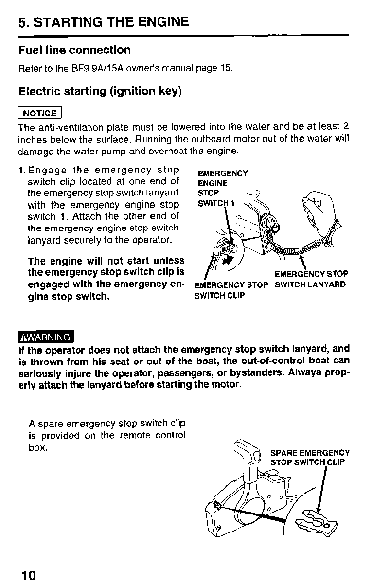
Fuel line connection
Refer to the BF9.9A/15A owner’s manual page 15.
Electric starting (ignition key)
The anti-ventilation plate must be lowered into the water and be at least 2
inches below the surface. Running the outboard motor out of the water will
damage the water pump and overheat the engine.
l.Engage the emergency stop EMERGENCY
switch clip located at one end of ENGINE
the emergency stop switch lanyard
with the emergency engine stop
switch 1. Attach the other end of
the emergency engine stop switch
lanyard securely to the operator.
The engine will not start unless
the emergency stop switch clip is
engaged with the emergency en- EMERGENCY STOP SWITCH LANYARD
gine stop switch. SWITCH CLIP
If the operator does not attach the emergency stop switch lanyard, and
is thrown from his seat or out of the boat, the out-of-control boat can
seriously injure the operator, passengers, or bystanders. Always prop-
erly attach the lanyard before starting the motor.
A spare emergency stop switch clip
is provided on the remote control
box.
10
5. STARTING THE ENGINE
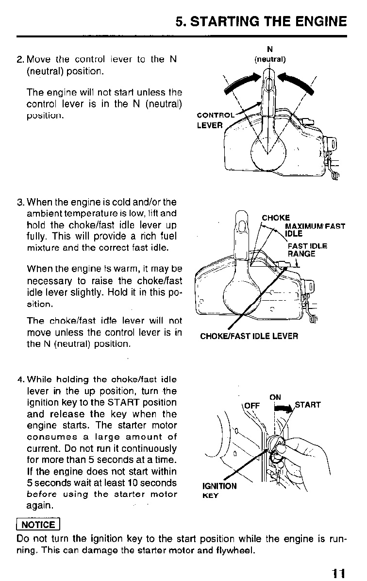
2. Move the control lever to the N
(neutral) position.
The engine will not start unless the
control lever is in the N (neutral)
position.
3. When the engine is cold and/or the
ambient temperature is low, lift and
hold the choke/fast idle lever up
fully. This will provide a rich fuel
mixture and the correct fast idle.
When the engine is warm, it may be
necessary to raise the choke/fast
idle lever slightly. Hold it in this po-
sition.
The choke/fast idle lever will not
move unless the control lever is in
the N (neutral) position.
4. While holding the choke/fast idle
lever in the up position, turn ,the
ignition key to the START position
and release the key when the
engine starts. The starter motor
consumes a large amount of
current. Do not run it continuously
for more than 5 seconds at a time.
If the engine does not start within
5 seconds wait at least 10 seconds
before using the starter motor
again.
N
(neytral)
MAXIMUM’FAST
CHOKE/FAST IDLE LEVER
ON
KEY
Do not turn the ignition key to the start position while the engine is run-
ning. This can damage the starter motor and flywheel.
11
5. STARTING THE ENGINE
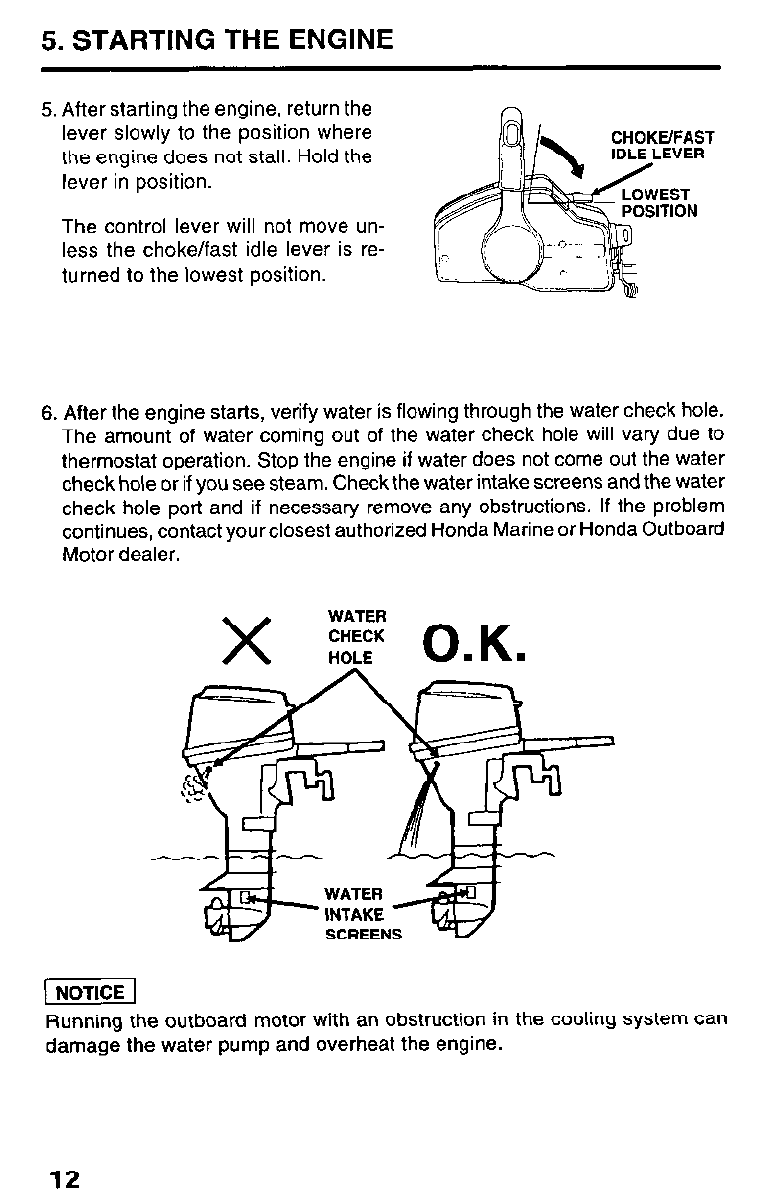
5. After starting the engine, return the
lever slowly to the position where
the engine does not stall. Hold the
lever in position.
CHOKE’FAST
The control lever will not move un-
less the choke/fast idle lever is re-
turned to the lowest position.
6. After the engine starts, verify water is flowing through the water check hole.
The amount of water coming out of the water check hole will vary due to
thermostat operation. Stop the engine if water does not come out the water
check hole or if you see steam. Check the water intake screens and the water
check hole port and if necessary remove any obstructions. If the problem
continues, contact yourclosest authorized Honda Marine or Honda Outboard
Motor dealer.
X WATER
CHECK
HOLE O.K.
Running the outboard motor with an obstruction in the cooling system can
damage the water pump and overheat the engine.
12
5. STARTING THE ENGINE
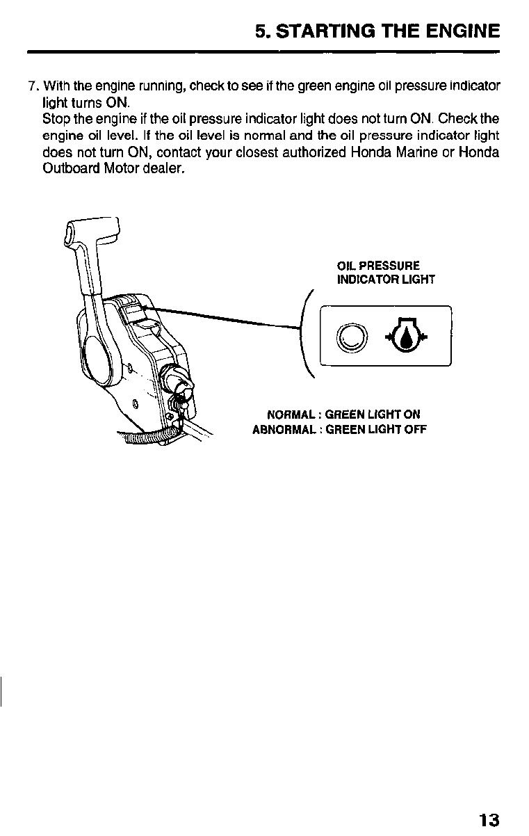
7. With the engine running, check to see if the green engine oil pressure indicator
light turns ON.
Stop the engine if the oil pressure indicator light does not turn ON. Check the
engine oil level. If the oil level is normal and the oil pressure indicator light
does not turn ON, contact your closest authorized Honda Marine or Honda
Outboard Motor dealer.
NORMAL
ABNORMAL
OIL PRESSURE
INDICATOR LIGHT
: GREEN LIGHT ON
: GREEN LIGHT OFF
13
5. STARTING THE ENGINE
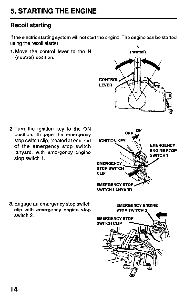
Recoil starting
If the electric starting system will not start the engine. The engine can be started
using the recoil starter. N
1. Move the control lever to the N (neutral)
(neutral) position.
2.Turn the ignition key to the ON
position. Engage the emergency
stop switch clip, located at one end
of the emergency stop switch
lanyard, with emergency engine
stop switch 1.
3. Engage an emergency stop switch
clip with emergency engine stop
switch 2.
CONTR
LEVER
EMERGENCY
ENGINE STOP
CHl
EMERGENCY ST0
SWITCH LANYARD
EMERGENCY ENGINE
STOP SWITCH 2
14
5. STARTING THE ENGINE
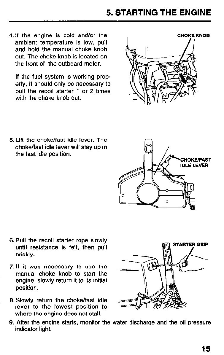
4. If the engine is cold and/or the
ambient temperature is low, pull
and hold the manual choke knob
out. The choke knob is located on
the front of the outboard motor.
If the fuel system is working prop-
erly, it should only be necessary to
pull the recoil starter 1 or 2 times
with the choke knob out.
;NOB
5. Lift the choke/fast idle lever. The
choke/fast idle lever will stay up in
the fast idle position.
CHOKE/FAST
6. Pull the recoil starter rope slowly
until resistance is felt, then pull
briskly.
7.If it was necessary to use the _
manual choke knob to start the
engine, slowly return it to its initial
position.
8. Slowly return the choke/fast idle
lever to the lowest position to
where the engine does not stall.
9. After the engine starts, monitor the water discharge and the oil pressure
indicator light.
15
5. STARTING THE ENGINE
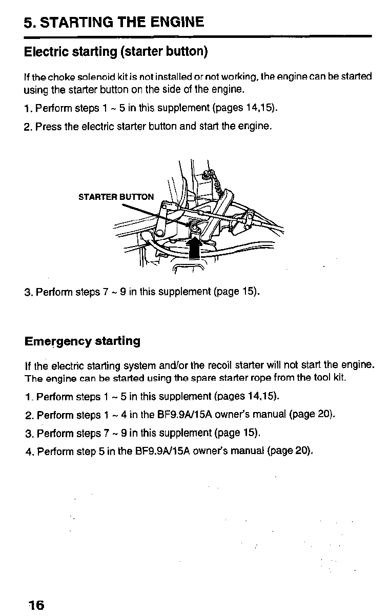
Electric starting (starter button)
If the choke solenoid kit is not installed or not working, the engine can be started
using the starter button on the side of the engine.
1. Perform steps 1 - 5 in this supplement (pages 14,15).
2. Press the electric starter button and start the engine.
3. Perform steps 7 - 9 in this supplement (page 15).
Emergency starting
If the electric starting system and/or the recoil starter will not start the engine.
The engine can be started using the spare starter rope from the tool kit.
1. Perform steps 1 - 5 in this supplement (pages 14,15).
2. Perform steps 1 - 4 in the BF9.9AI15A owner’s manual (page 20).
3. Perform steps 7 - 9 in this supplement (page 15).
4. Perform step 5 in the BF9.9N15A owner’s manual (page 20).
16
6. OPERATION
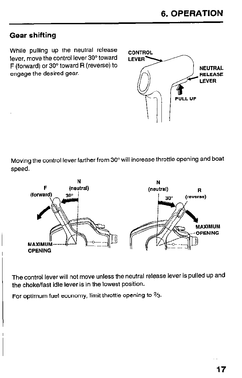
Gear shifting
While pulling up the neutral release CONTROL
lever, move the control lever 30” toward
F (forward) or 30” toward R (reverse) to NEUTRAL
engage the desired gear. RELEASE
LEVER
Moving the control lever farther from 30” will increase throttle opening and boat
speed.
N N
F (neutral) (neutral) R
The control lever will not move unless the neutral release lever is pulled up and
the choke/fast idle lever is in the lowest position.
For optimum fuel economy, limit throttle opening to Vs.
17
7. STOPPING THE ENGINE
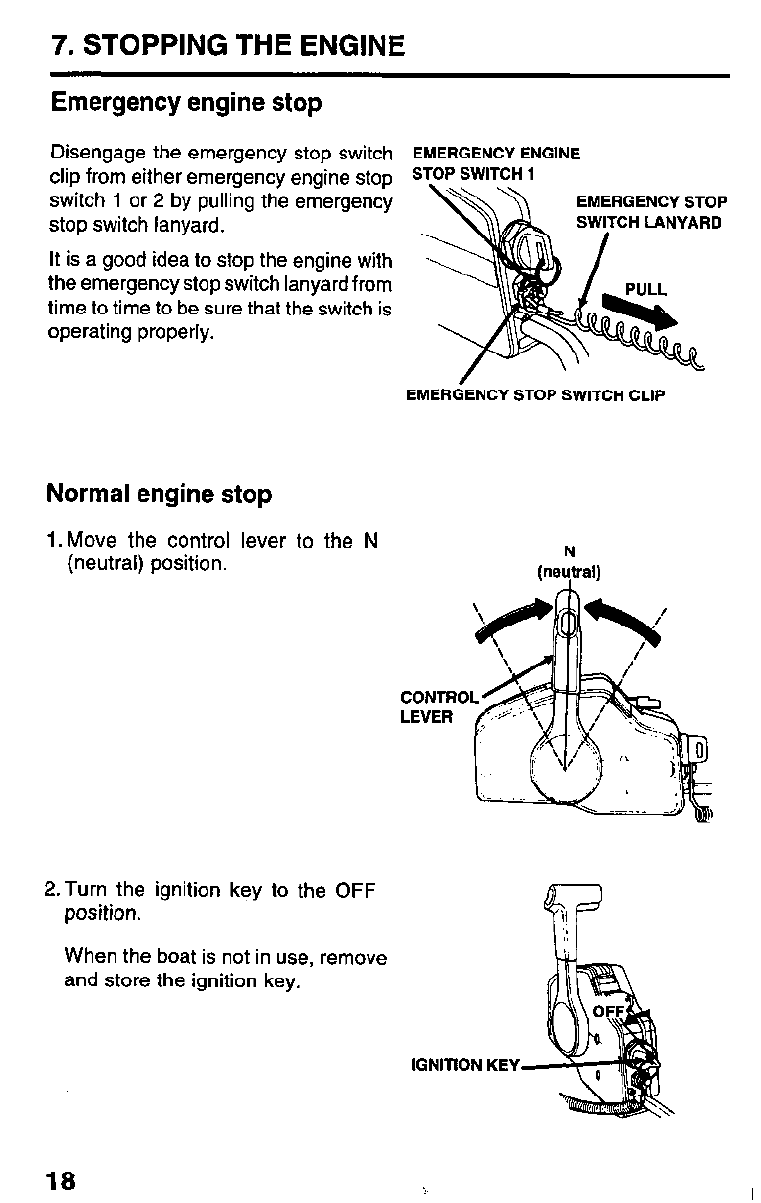
Emergency engine stop
Disengage the emergency stop switch EMERGENCY ENGINE
clip from either emergency engine stop STOP SWITCH 1
switch 1 or 2 by pulling the emergency
stop switch lanyard.
It is a good idea to stop the engine with
the emergency stop switch lanyard from
time to time to be sure that the switch is
operating properly.
EMERGENCY STOP SWITCH CLIP
Normal engine stop
1. Move the control lever to the N
(neutral) position.
2.Turn the ignition key to the OFF
position.
When the boat is not in use, remove
and store the ignition key.
@e&al)
CONTRO
LEVER
IGNITION KEY
18
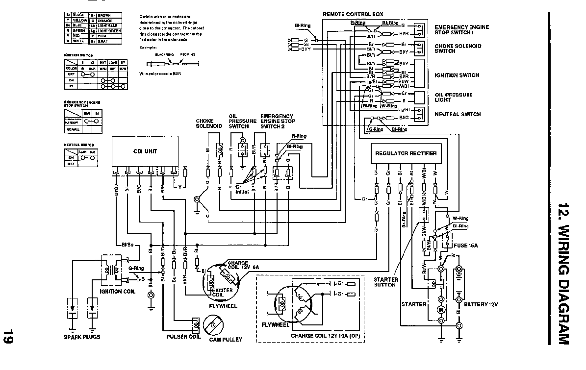
12. WIRING DIAGRAM
13. OPTIONAL PARTS
Steering lube Seal
(Anodized Aluminum or Stainless Steel)
There are additional optional parts available. See your authorized Honda
Marine or Honda Outboard Motor dealer for a complete list.
20


31 ZV46QA 2509307
00X31-ZV4-6OOA PRINTED IN U.S.A.
I
I
I
I
I
I
I