Honda Ex5500 Ea1 1000001 Through 1099999 Owners Manual
2014-11-13
: Honda Honda-Ex5500-Ea1-1000001-Through-1099999-Owners-Manual-108486 honda-ex5500-ea1-1000001-through-1099999-owners-manual-108486 honda pdf
Open the PDF directly: View PDF ![]() .
.
Page Count: 57
Thank you for purchasing a Honda generator.
We want to help you get the best results from your new generator and
to operate it safely. This manual contains the information on how to
do that; please read it carefully.
This owner’s manual describes the operation and maintenance of the
Honda Generator: EX5500.
All information in this publication is based on the latest product
information available at the time of printing.
Honda Motor Co., Ltd. reserves the right to make changes at any time
without notice and without incurring any obligation.
No part of this publication may be reproduced without written
permission.
This manual should be considered a permanent part of the generator
and should remain with it if it is resold.
Safety Messages
Your safety and the safety of others is very important. We have
provided important safety messages in this manual and on the
generator. Please read these messages carefully.
A safety message alerts you to potential hazards that could hurt you
or others. Each safety message is
A c!f
receded by a safety alert symbol
and one of three words: DAN El?, WARNING, or CAUTION.
These mean
m You WILL be KILLED or SERIOUSLY HURT if you don’t
follow instructions.
B You CAN be KILLED or SERIOUSLY HURT if you don’t
follow instructions.
w You CAN be HURT if you don’t follow instructions.
Each message tells you what the hazard is, what can happen, and
what you can do to avoid or reduce injury.
Damage Prevention Messages
You will also see other important messages that are preceded by the
word NOTICE.
This word means:
1 NOTICE 1
Your generator or other property could be damaged if you
don’t follow instructions.
The purpose of these messages is to help prevent damage to your
generator, other property, or the environment.
1
CONTENTS
SAFETY ....................................................................................................... 4
Safety Label Locations ........................................................................ 4
Safety Information ............................................................................... 6
COMPONENT IDENTIFICATION ............................................................... 8
CONTROLS ............................................................................................... 10
Engine Switch ..................................................................................... 10
Circuit Breaker .................................................................................... 10
Fuel Valve ........................................................................................... 11
Ground Terminal ................................................................................ 11
Voltage Adjustment Knob ................................................................. 12
Volt Meter ........................................................................................... 12
Auto-throttle System ......................................................................... 13
Pilot Lamp ........................................................................................... 13
Oil Pressure Lamp .............................................................................. 14
GENERATOR USE .................................................................................... 15
Connections to a Building’s Electrical System ................................ 15
Ground System .................................................................................. 15
Special Requirements ........................................................................ 15
AC Applications .................................................................................. 16
AC Operation ...................................................................................... 17
AC Receptacle Selection .................................................................... 18
Auto-throttle System ......................................................................... 19
High Altitude Operation ..................................................................... 20
PRE-OPERATION CHECK ........................................................................ 21
Engine Oil ........................................................................................... 21
Fuel Recommendation ...................................................................... 22
Coolant ................................................................................................ 24
STARTING THE ENGINE ......................................................................... 26
STOPPING THE ENGINE ......................................................................... 27
MAINTENANCE ....................................................................................... 28
Maintenance Schedule ...................................................................... 28
Emission Control System .................................................................. 29
Engine Oil and Oil Filter Change ....................................................... 30
Air Cleaner Service ............................................................................ 32
Spark Plug Service ............................................................................. 33
Fuel Sediment Cup Cleaning ............................................................ 34
Fuse Replacement .............................................................................. 35
Spark Arrester Maintenance ............................................................. 36
Battery ................................................................................................. 37
2
TRANSPORTING/STORAGE ................................................................... 39
TROUBLESHOOTING .............................................................................. 41
WIRING DIAGRAM ..................................................................................
SPECIFICATIONS ..................................................................................... ii
INSTALLATION OF OPTIONAL PARTS .................................................. 45
CUSTOMER SERVICE INFORMATION ................................................... 49
INDEX ....................................................................................................... 50
3
SAFETY
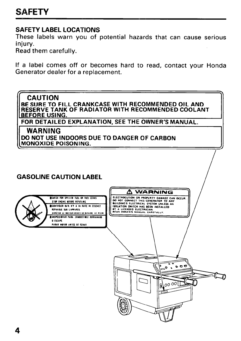
SAFETY LABEL LOCATIONS
These labels warn you of potential hazards that can cause serious
injury.
Read them carefully.
If a label comes off or becomes hard to read, contact your Honda
Generator dealer for a replacement.
/r .
CAUTION
BE SURE TO FILL CRANKCASE WITH RECOMMENDED OIL AND
RESERVE TANK OF RADIATOR WITH RECOMMENDED COOLANT
BEFORE USING.
FOR DETAILED EXPLANATION, SEE THE OWNER’S MANUAL.
1 WARNING I
NOT USE INDOORS DUE TO DANGER OF CARBON
NOXIDE POISONING. 1
I-
GASOLINE CAUTION LABEL I
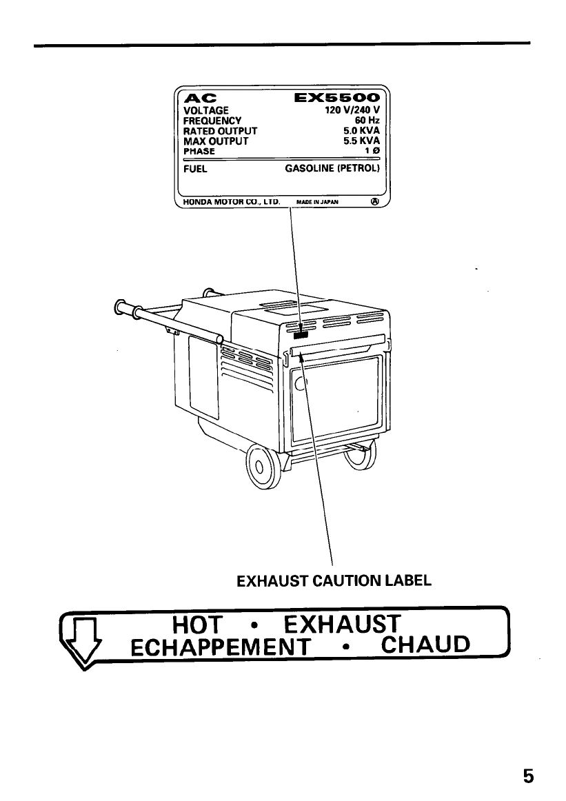
AC EX5500
VOLTAGE
FREQUENCY
RATED OUTPUT
MAX OUTPUT
PHASE
FUEL
120 VI240 v
SO Hz
5.0 KVA
5.5 KVA
10
GASOLINE (PETROL)
EXHAUST CAUTION LABEL
HOT l EXHAUST 3
ECHAPPEMENT l CHAUD
I
5
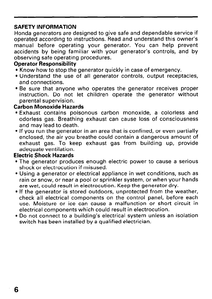
SAFETY INFORMATION
Honda generators are designed to give safe and dependable service if
operated according to instructions. Read and understand this owner’s
manual before operating your generator. You can help prevent
accidents by being familiar with your generator’s controls, and by
observing safe operating procedures.
Operator Responsibility
l Know how to stop the generator quickly in case of emergency.
l Understand the use of all generator controls, output receptacles,
and connections.
l Be sure that anyone who operates the generator receives proper
instruction. Do not let children operate the generator without
parental supervision.
Carbon Monoxide Hazards
l Exhaust contains poisonous carbon monoxide, a colorless and
odorless gas. Breathing exhaust can cause loss of consciousness
and may lead to death.
l If you run the generator in an area that is confined, or even partially
enclosed, the air you breathe could contain a dangerous amount of
exhaust gas. To keep exhaust gas from building up, provide
adequate ventilation.
Electric Shock Hazards
l The generator produces enough electric power to cause a serious
shock or electrocution if misused.
l Using a generator or electrical appliance in wet conditions, such as
rain or snow, or near a pool or sprinkler system, or when your hands
are wet, could result in electrocution. Keep the generator dry.
l If the generator is stored outdoors, unprotected from the weather,
check all electrical components on the control panel, before each
use. Moisture or ice can cause a malfunction or short circuit in
electrical components which could result in electrocution.
l Do not connect to a building’s electrical system unless an isolation
switch has been installed by a qualified electrician.
Fire and Burn Hazards
l The exhaust system gets hot enough to ignite some materials.
-Keep the generator at least 1 meter (3 feet) away from buildings
and other equipment during operation.
-Do not enclose the generator in any structure.
-Keep flammable materials away from the generator.
l The muffler becomes very hot during operation and remains hot for
a while after stopping the engine. Be careful not to touch the muffler
while it is hot. Let the engine cool before storing the generator
indoors.
l Gasoline is extremely flammable and is explosive under certain
conditions. Do not smoke or allow flames or sparks where the
generator is refueled or where gasoline is stored. Refuel in a well-
ventilated area with the engine stopped.
l Fuel vapors are extremely flammable and may ignite after the
engine has started. Make sure that any spilled fuel has been wiped
up before starting the generator.
7
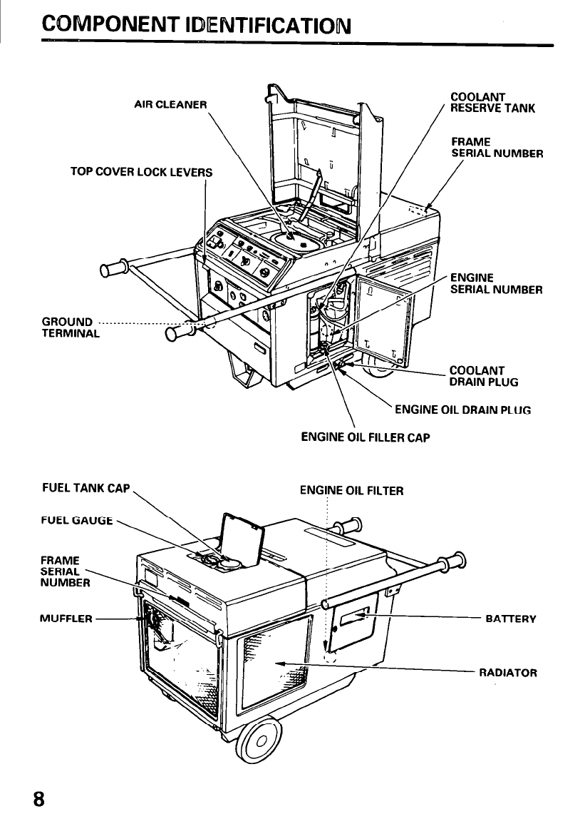
COMPONENT IDENTIFICATION
AIR CLEANER j COOLANT
/
RESERVE TANK
/ FRAME
SERIAL NUMBER
TOP COVER LOCK LEVE
GROUND . . . . . . . . .._______
TERMINAL
COOLANT
DRAIN PLUG
\
’ ENGINE OIL DRAIN PLUG
ENGINE OIL FILLER CAP
FUEL TANK CAP \ ENGINE OIL FILTER
FUEL GAUGE \\
MUFFLER - BAlTERY
- RADIATOR
8
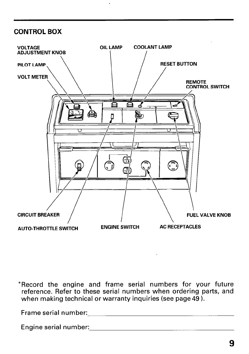
CONTROL BOX
VOLTAGE
ADJUSTMENT KNOB OIL LAMP COOLANT LiMP
RESET BUTTON
REMOTE
CONTROL SWITCH
CIRCUIT BREAKER FUEL VALVE KNOB
AUTO-THROTTLE SWITCH ENGINE SWITCH AC RECEPTACLES
*Record the engine and frame serial numbers for your future
reference. Refer to these serial numbers when ordering parts, and
when making technical or warranty inquiries (see page 49 ).
Frame serial number:
Engine serial number:
COMTROLS
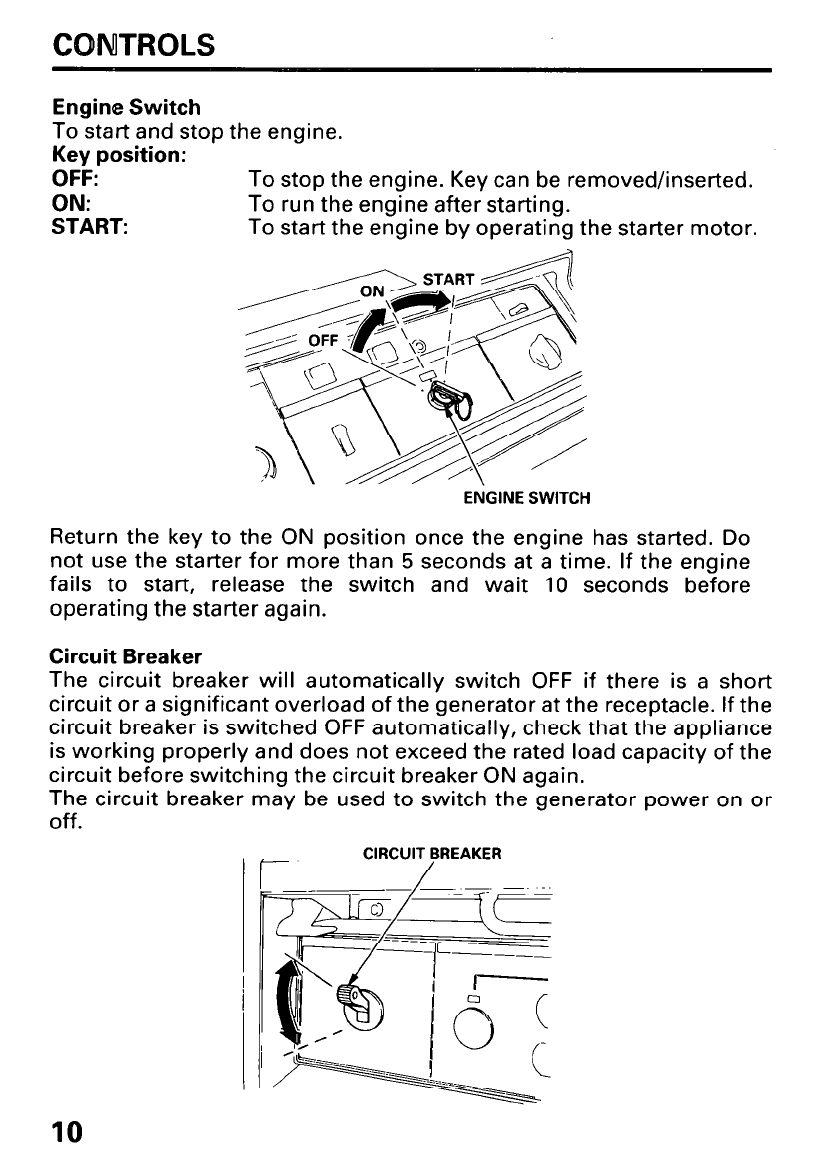
Engine Switch
To start and stop the engine.
Key position:
OFF: To stop the engine. Key can be removed/inserted.
ON: To run the engine after starting.
START: To start the engine by operating the starter motor.
ENGINE SWITCH
Return the key to the ON position once the engine has started. Do
not use the starter for more than 5 seconds at a time. If the engine
fails to start, release the switch and wait 10 seconds before
operating the starter again.
Circuit Breaker
The circuit breaker will automatically switch OFF if there is a short
circuit or a significant overload of the generator at the receptacle. If the
circuit breaker is switched OFF automatically, check that the appliance
is working properly and does not exceed the rated load capacity of the
circuit before switching the circuit breaker ON again.
The circuit breaker may be used to switch the generator power on or
Off.
II CIRCUIT BREAKER
/
10
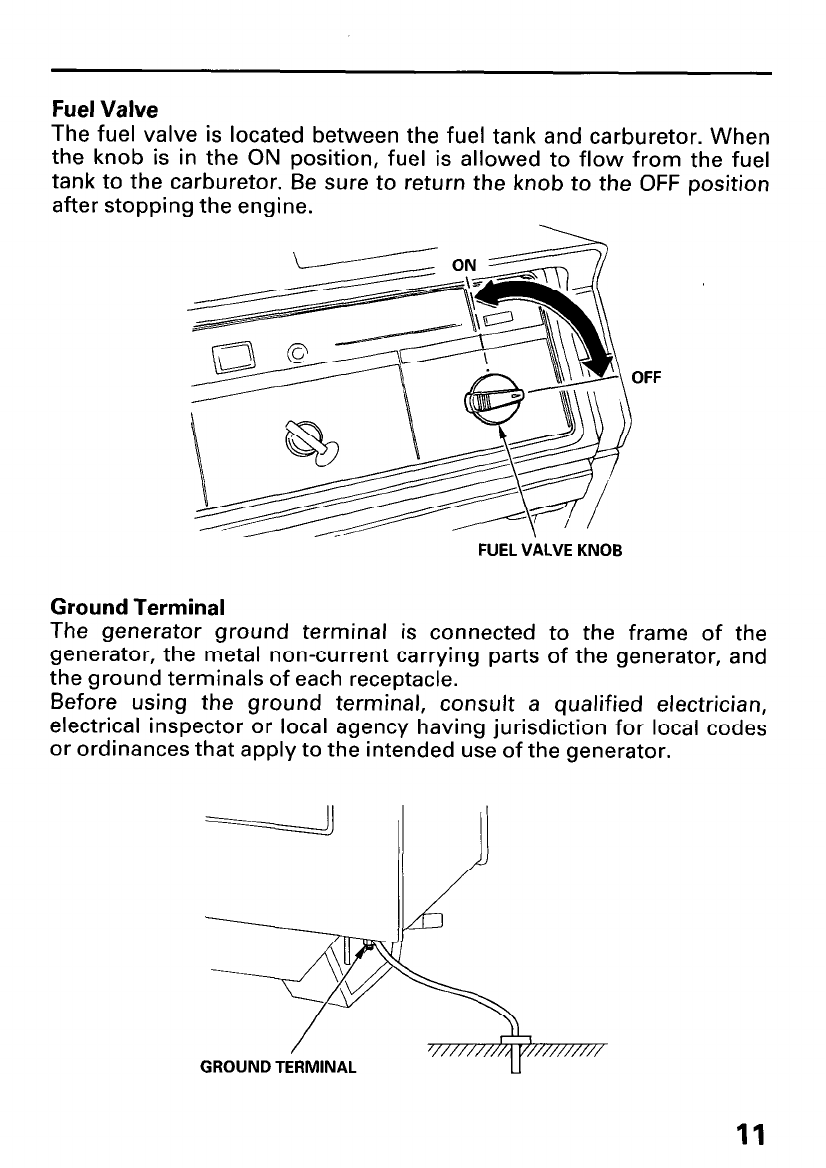
Fuel Valve
The fuel valve is located between the fuel tank and carburetor. When
the knob is in the ON position, fuel is allowed to flow from the fuel
tank to the carburetor. Be sure to return the knob to the OFF position
after stopping the engine.
OFF
FUEL VALVE KNOB
Ground Terminal
The generator ground terminal is connected to the frame of the
generator, the metal non-current carrying parts of the generator, and
the ground terminals of each receptacle.
Before using the ground terminal, consult a qualified electrician,
electrical inspector or local agency having jurisdiction for local codes
or ordinances that apply to the intended use of the generator.
GROUND TERMINAL
11
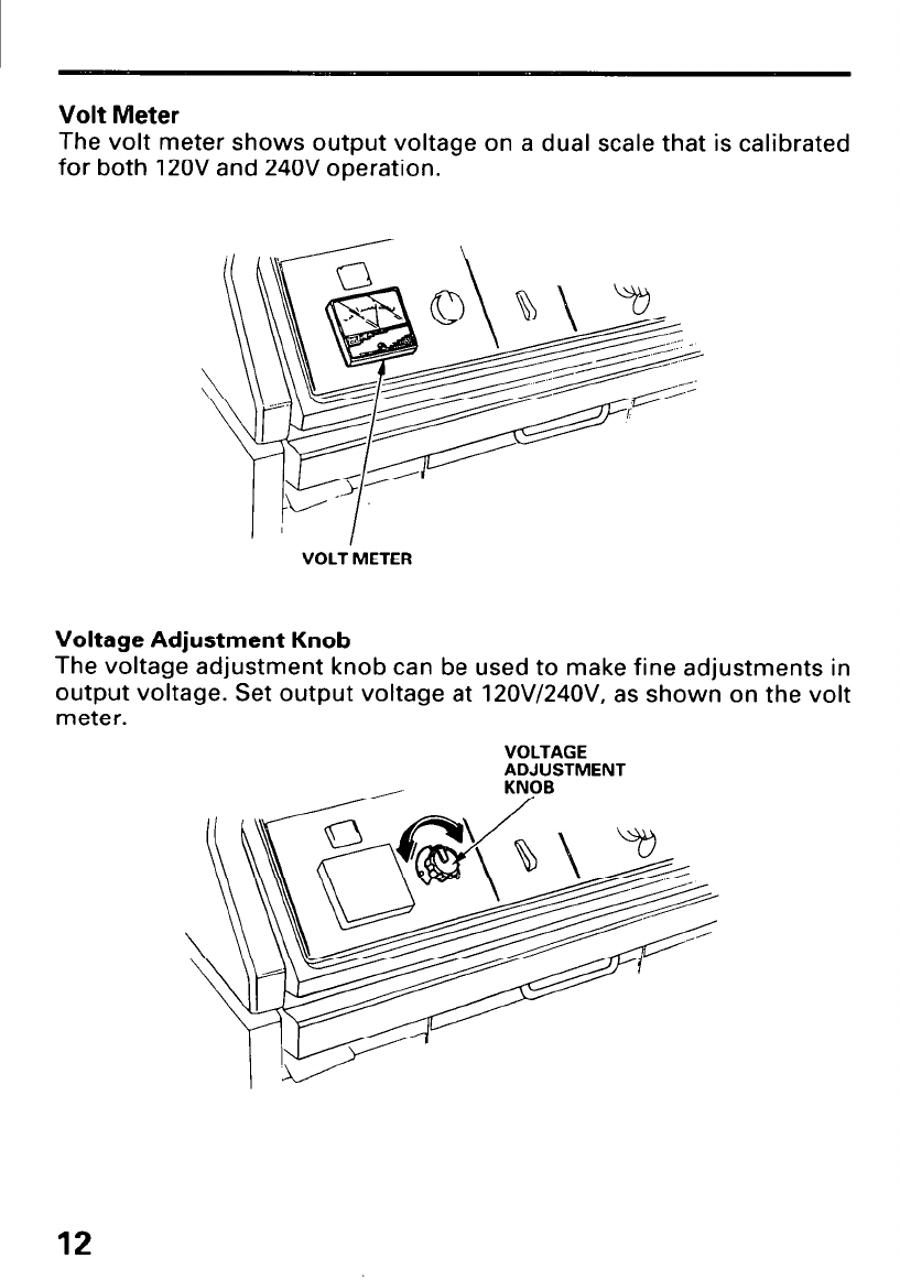
Volt Meter
The volt meter shows output voltage on a dual scale that is calibrated
for both 120V and 240V operation.
VOLT METER
Voltage Adjustment Knob
The voltage adjustment knob can be used to make fine adjustments in
output voltage. Set output voltage at 12OV/24OV, as shown on the volt
meter.
VOLTAGE
ADJUSTMENT
12
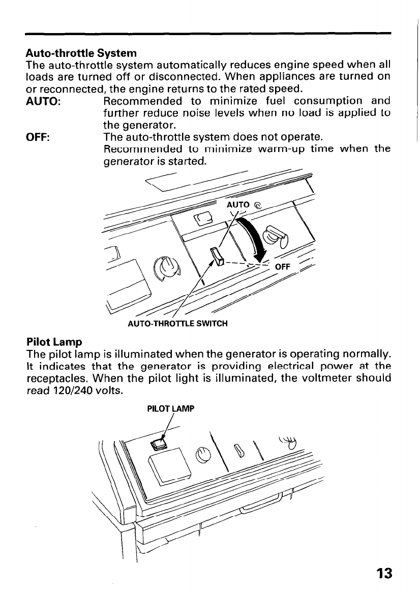
Auto-throttle System
The auto-throttle system automatically reduces engine speed when all
loads are turned off or disconnected. When appliances are turned on
or reconnected, the engine returns to the rated speed.
AUTO: Recommended to minimize fuel consumption and
further reduce noise levels when no load is applied to
the generator.
OFF: The auto-throttle system does not operate.
Recommended to minimize warm-up time when the
generator is started.
AUTO-THRhLE SWITCH
Pilot Lamp
The pilot lamp is illuminated when the generator is operating normally.
It indicates that the generator is providing electrical power at the
receptacles. When the pilot light is illuminated, the voltmeter should
read 120/240 volts.
PILOT LAMP
/
13
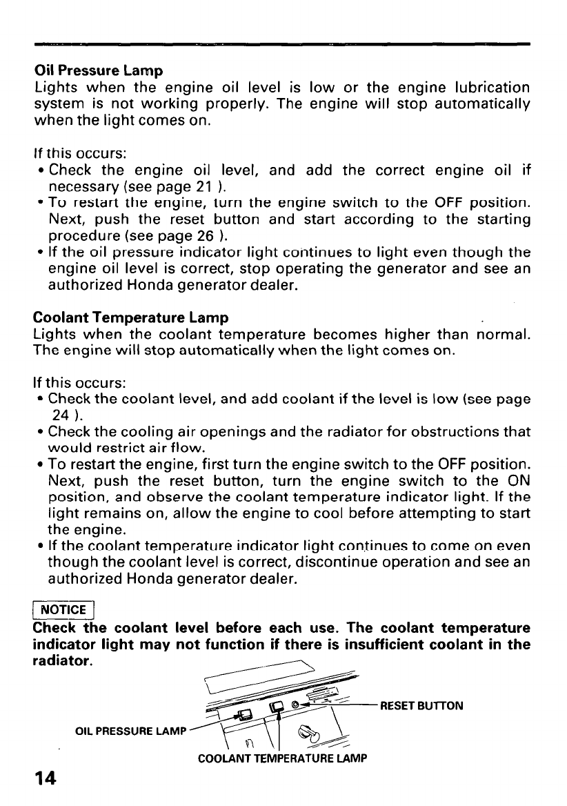
Oil Pressure Lamp
Lights when the engine oil level is low or the engine lubrication
system is not working properly. The engine will stop automatically
when the light comes on.
If this occurs:
l Check the engine oil level, and add the correct engine oil if
necessary (see page 21 1.
l To restart the engine, turn the engine switch to the OFF position.
Next, push the reset button and start according to the starting
procedure (see page 26 ).
l If the oil pressure indicator light continues to light even though the
engine oil level is correct, stop operating the generator and see an
authorized Honda generator dealer.
Coolant Temperature Lamp
Lights when the coolant temperature becomes higher than normal.
The engine will stop automatically when the light comes on.
If this occurs:
l Check the coolant level, and add coolant if the level is low (see page
24 ).
l Check the cooling air openings and the radiator for obstructions that
would restrict air flow.
l To restart the engine, first turn the engine switch to the OFF position.
Next, push the reset button, turn the engine switch to the ON
position, and observe the coolant temperature indicator light. If the
light remains on, allow the engine to cool before attempting to start
the engine.
l If the coolant temperature indicator light continues to come on even
though the coolant level is correct, discontinue operation and see an
authorized Honda generator dealer.
[ NOTICE 1
Check the coolant
indicator light may
radiator.
level before each use. The coolant temperature
not function if there is insufficient coolant in the
RESET BUlTON
OIL PRESSURE LAMP
COOLANT TEMPERATURE LAMP
14
GENERATOR USE
Connections to a Building’s Electrical System
Connections for standby power to a building’s electrical system must
be made by a qualified electrician. The connection must isolate the
generator power from utility power, and must comply with all
applicable laws and electrical codes.
Improper connections to a building’s electrical system can allow
electrical current from the generator to backfeed into the utility lines.
Such backfeed may electrocute utility company workers or others
who contact the lines during a power outage. Consult the utility
company or a qualified electrician.
) NOTICE )
Improper connections to a building’s electrical system can allow
electrical current from the utility company to backfeed into the
generator. When utility power is restored, the generator may explode,
burn, or cause fires in the building’s electrical system.
Ground System
Honda portable generators have a system ground that connects
generator frame components to the ground terminals in the AC output
receptacles. The system ground is not connected to the AC neutral
wire. If the generator is tested by a receptacle tester, it will not show
the same ground circuit condition as for a home receptacle.
Special Requirements
There may be Federal or State Occupational Safety and Health
Administration (OSHA) regulations, local codes, or ordinances that
apply to the intended use of the generator. Please consult a qualified
electrician, electrical inspector, or the local agency having jurisdiction.
l In some areas, generators are required to be registered with local
utility companies.
l If the generator is used at a construction site, there may be
additional regulations which must be observed.
15
AC Applications
Before connecting an appliance or power cord to the generator:
l Make sure that it is in good working order. Faulty appliances or
power cords can create a potential for electrical shock.
l If an appliance begins to operate abnormally, becomes sluggish or
stops suddenly, turn it off immediately. Disconnect the appliance,
and determine whether the problem is the appliance, or if the rated
load capacity of the generator has been exceeded.
l Make sure that the electrical rating of the tool or appliance does not
exceed that of the generator. Never exceed the maximum power
rating of the generator. Power levels between rated and maximum
may be used for no more than 30 minutes.
Substantial overloading will open the circuit breaker. Exceeding the
time limit for maximum power operation or slightly overloading the
generator may not switch the circuit breaker OFF, but will shorten the
service life of the generator.
Limit operation requiring maximum power to 30 minutes.
Maximum power is:
5.5 kVA
For continuous operation, do not exceed the rated power.
Rated power is:
5.0 kVA
In either case, the total power requirements (VA) of all appliances
connected must be considered. Appliance and power tool
manufacturers usually list rating information near the model number
or serial number.
16
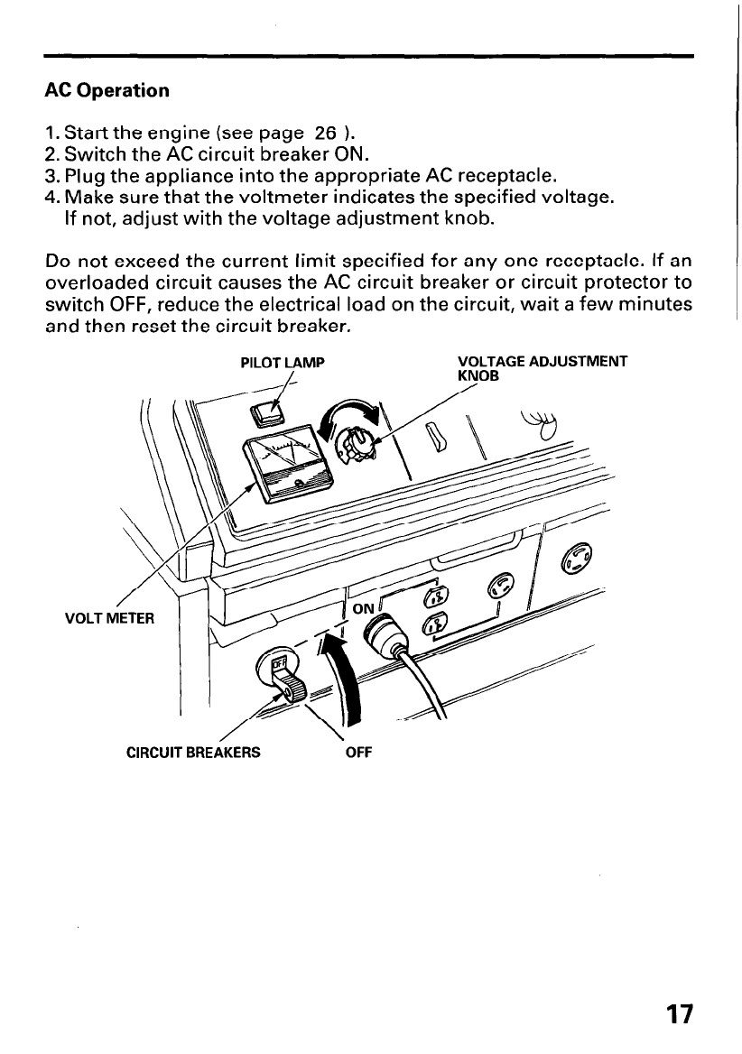
AC Operation
1. Start the engine (see page 26 1.
2. Switch the AC circuit breaker ON.
3. Plug the appliance into the appropriate AC receptacle.
4. Make sure that the voltmeter indicates the specified voltage.
If not, adjust with the voltage adjustment knob.
Do not exceed the current limit specified for any one receptacle. If an
overloaded circuit causes the AC circuit breaker or circuit protector to
switch OFF, reduce the electrical load on the circuit, wait a few minutes
and then reset the circuit breaker.
VOLT
CIRCUIT BREAKERS OFF
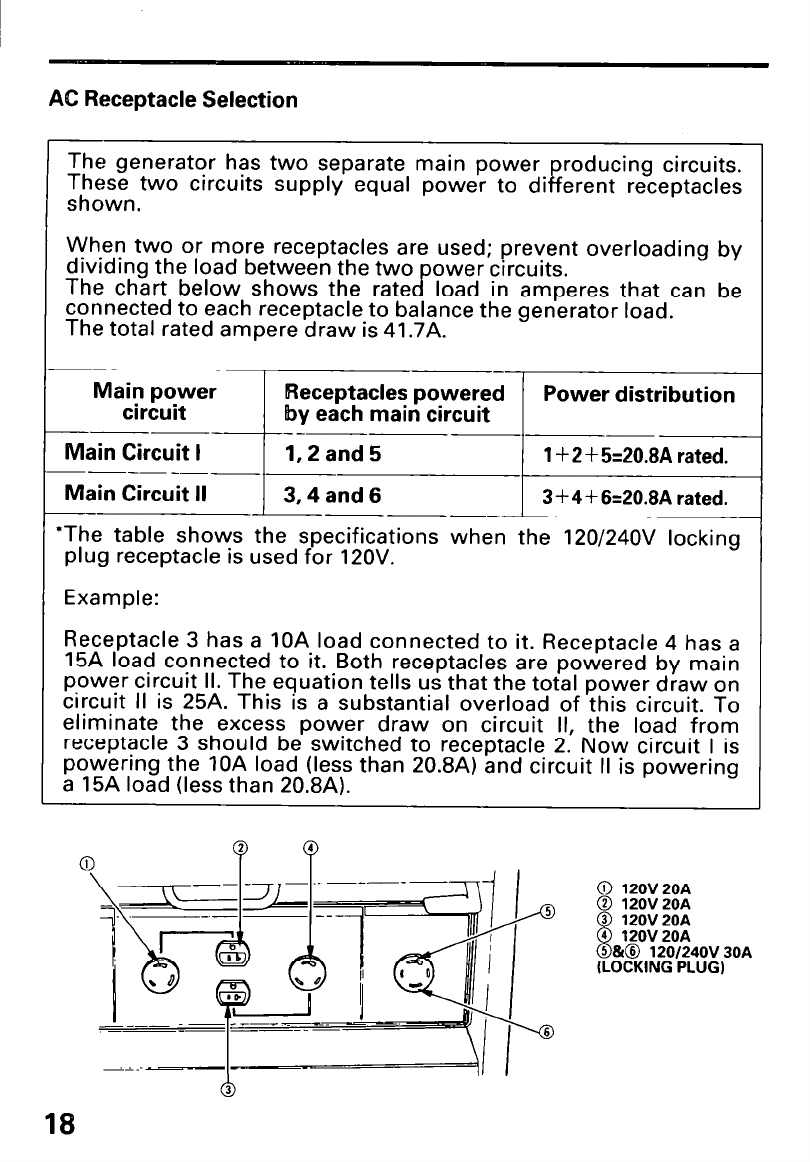
AC Receptacle Selection
The generator has two separate main power
These two circuits supply equal power to di
R reducing circuits.
shown. erent receptacles
Main Circuit II
--
‘The table shows the specifications when the 120/24OV locking
plug receptacle is used for 120V.
Example:
Receptacle 3 has a 10A load connected to it. Receptacle 4 has a
15A load connected to it. Both receptacles are powered by main
power circuit II. The equation tells us that the total power draw on
circuit II is 25A. This is a substantial overload of this circuit. To
eliminate the excess power draw on circuit II, the load from
receptacle 3 should be switched to receptacle 2. Now circuit I is
powering the IOA load (less than 20.8A) and circuit II is powering
a 15A load (less than 20.8A).
18
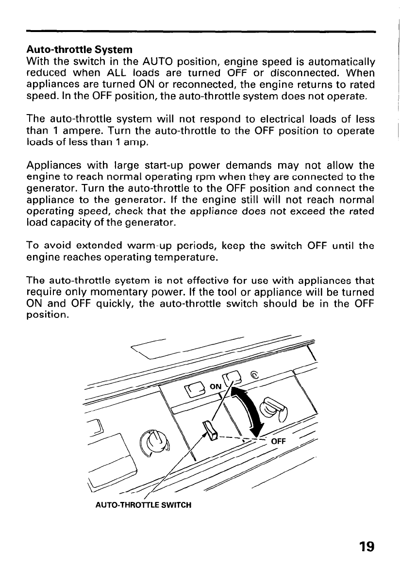
Auto-throttle System
With the switch in the AUTO position, engine speed is automatically
reduced when ALL loads are turned OFF or disconnected. When
appliances are turned ON or reconnected, the engine returns to rated
speed. In the OFF position, the auto-throttle system does not operate.
The auto-throttle system will not respond to electrical loads of less
than 1 ampere. Turn the auto-throttle to the OFF position to operate
loads of less than 1 amp.
Appliances with large start-up power demands may not allow the
engine to reach normal operating rpm when they are connected to the
generator. Turn the auto-throttle to the OFF position and connect the
appliance to the generator. If the engine still will not reach normal
operating speed, check that the appliance does not exceed the rated
load capacity of the generator.
To avoid extended warm-up periods, keep the switch OFF until the
engine reaches operating temperature.
The auto-throttle system is not effective for use with appliances that
require only momentary power. If the tool or appliance will be turned
ON and OFF quickly, the auto-throttle switch should be in the OFF
position.
AUTO-THROTTLE SWITCH
19
l High Altitude Operation
At high altitude, the standard carburetor air-fuel mixture will be too
rich. Performance will decrease, and fuel consumption will increase. A
very rich mixture will also foul the spark plug and cause hard starting.
High altitude performance can be improved by specific modifications
to the carburetor. If you always operate your engine at altitudes above
1,800 meters (6,000 feet), have your dealer perform this carburetor
modification.
Even with carburetor modification, engine horsepower will decrease
about 3.5% for each 300 meter (1,000 foot) increase in altitude. The ef-
fect of altitude on horsepower will be greater than this if no carburetor
modification is made.
1 NOTICE )
When the carburetor has been modified for high altitude operation,
the air-fuel mixture will be too lean for low altitude use. Operation at
altitudes below 1,800 meters (6,000 feet) with a modified carburetor
may cause the engine to overheat and result in serious engine
damage. For use at low altitudes, have your dealer return the
carburetor to original factory specifications.
20
PRE-OPERATION CHECK
Engine Oil
piEiq
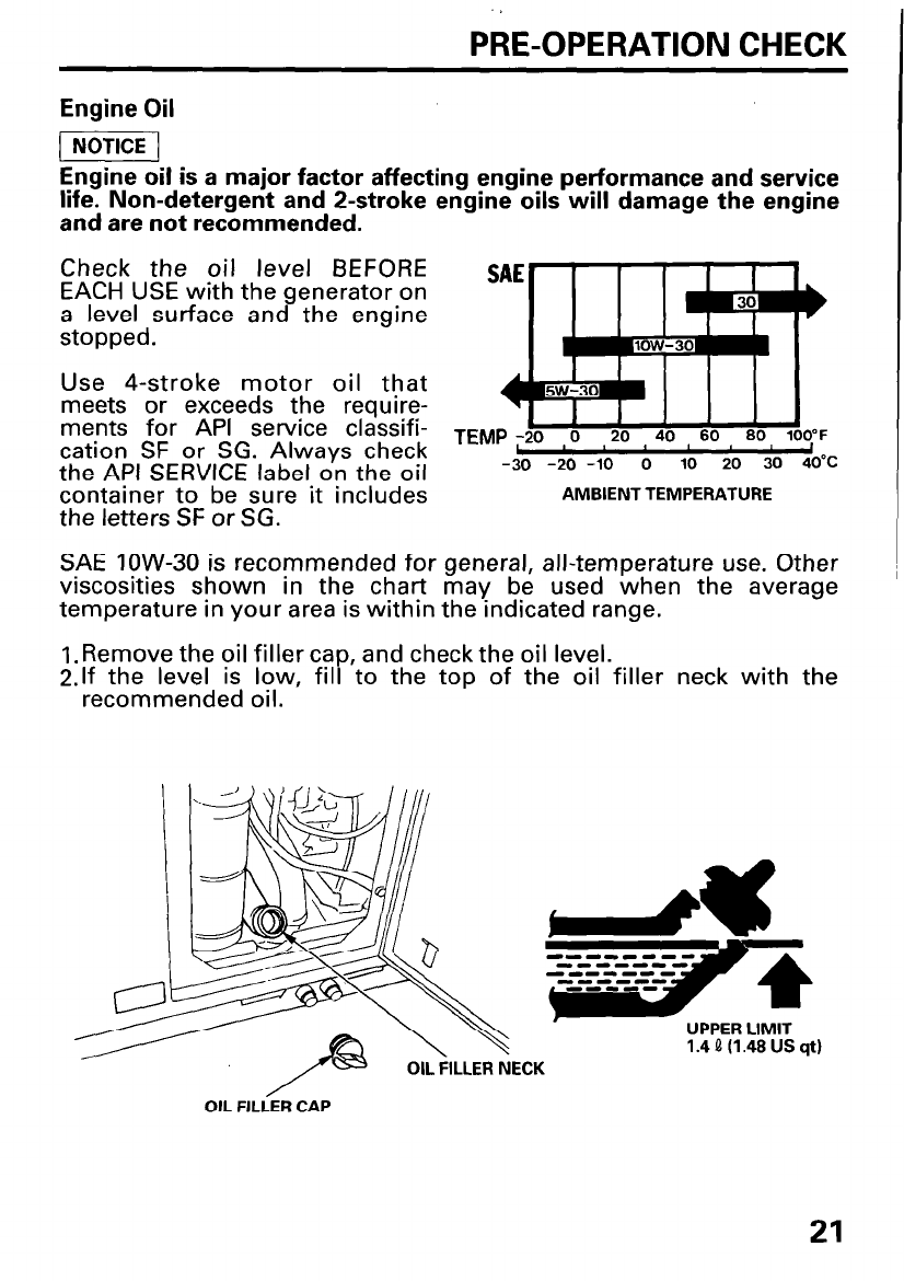
Engine oil is a major factor affecting engine performance and service
life. Non-detergent and P-stroke engine oils will damage the engine
and are not recommended.
Check the oil level BEFORE
EACH USE with the generator on
a level surface and the engine
stopped.
Use 4-stroke motor oil that
meets or exceeds the require-
ments for API service classifi-
cation SF or SG. Always check
the API SERVICE label on the oil -30 -20 -10 0 10 20 30 40°C
container to be sure it includes
the letters SF or SG.
AMBIENT TEMPERATURE
SAE low-30 is recommended for general, all-temperature use. Other
viscosities shown in the chart may be used when the average
temperature in your area is within the indicated range.
1. Remove the oil filler cap, and check the oil level.
2.lf the level is low, fill to the top of the oil filler neck with the
recommended oil.
21
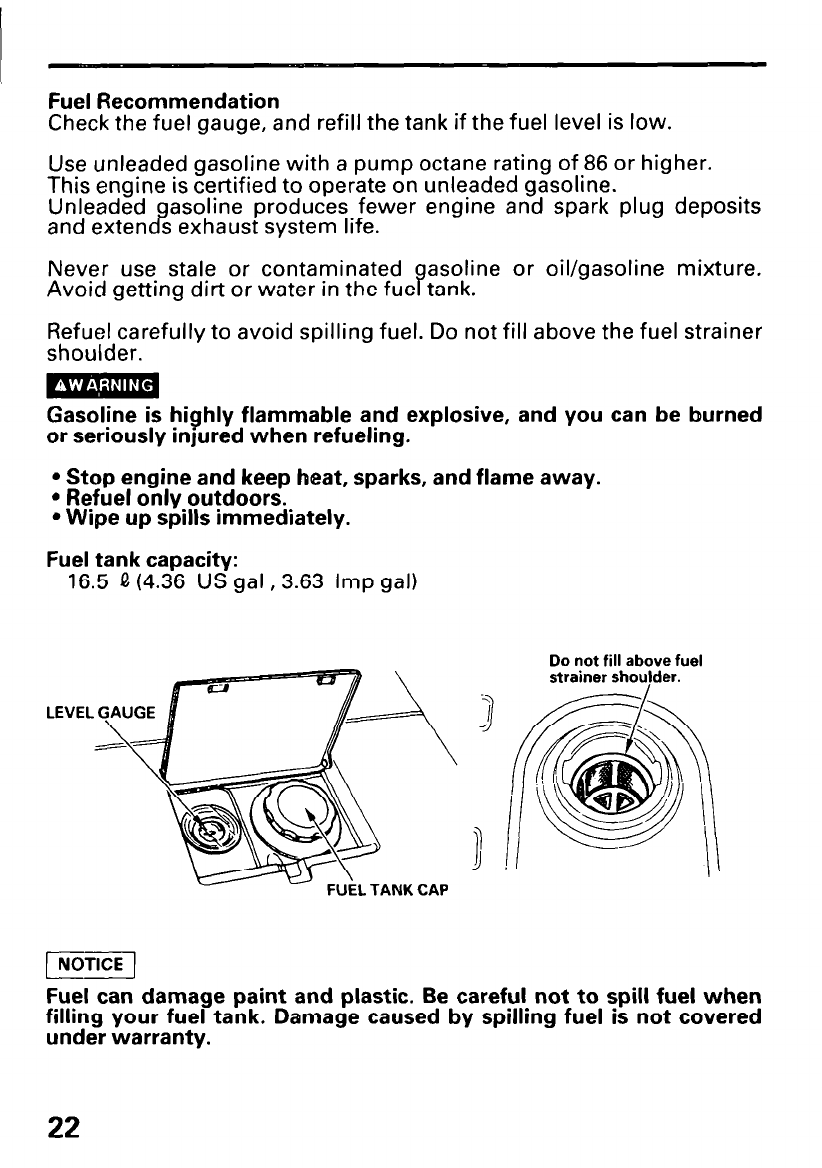
Fuel Recommendation
Check the fuel gauge, and refill the tank if the fuel level is low.
Use unleaded gasoline with a pump octane rating of 86 or higher.
This engine is certified to operate on unleaded gasoline.
Unleaded gasoline produces fewer engine and spark plug deposits
and extends exhaust system life.
Never use stale or contaminated asoline or oil/gasoline mixture.
Avoid getting dirt or water in the fue ?
tank.
Refuel carefully to avoid spilling fuel. Do not fill above the fuel strainer
shoulder.
Gasoline is highly flammable and explosive, and you can be burned
or seriously injured when refueling.
l Stop engine and keep heat, sparks, and flame away.
l Refuel only outdoors.
l Wipe up spills immediately.
Fuel tank capacity:
16.5 fI (4.36 US gal, 3.63 Imp gal)
Do not fill above fuel
LEVEL
Fuel can damage paint and plastic. Be careful not to spill fuel when
filling your fuel tank. Damage caused by spilling fuel is not covered
under warranty.
22
Occasionally you may hear light “spark knock” or “pinging” (metallic
rapping noise) while operating under heavy loads. This IS no cause for
concern.
If spark knock or pin
normal load, change %
ing occurs at a steady engine speed, under
rands of gasoline. If spark knock or pinging
persists, see an authorized Honda generator dealer.
riiziq
Running the engine with persistent spark knock or pinging can cause
engine damage.
Running the engine with persistent spark knock or pinging is misuse,
and the Distributor’s Limited Warranty does not cover parts damaged
by misuse.
Oxygenated Fuels
Some conventional gasolines are being blended with alcohol or an
ether compound. These gasolines are collectively referred to as
oxygenated fuels. To meet clean air standards, some areas of the
United Sates and Canada use oxygenated fuels to help reduce
emissions.
If you use an oxygenated fuel, be sure it is unleaded and meets the
minimum octane rating requirement.
Before using an oxygenated fuel, try to confirm the fuel’s contents.
Some states/provinces require this information to be posted on the
?Ee”
P
ollowing are the EPA approved percentages of oxygenates:
ETHANOL - (ethyl or grain alcohol) 10% by volume
You may use gasoline containing up to 10% ethanol by
volume. Gasoline containing ethanol may be marketed
under the name “Gasohol”.
MTBE - (methyl tertiary butyl ether) 15% by volume
Jz;,meay use gasoline contarnrng up to 15% MTBE by
METHANOL - (methyl or wood alcohol) 5% by volume
You may use gasoline containing up to 5% methanol
by volume as long as it also contains cosolvents and
corrosion inhibitors to protect the fuel system.
Gasoline containing more than 5% methanol by
volume may cause starting and/or performance
problems. It may also damage metal, rubber, and
plastic parts of your fuel system.
If you notice any undesirable operating symptoms, try another service
station or switch to another brand of gasoline.
Fuel system dama e or performance problems resulting from the use
of an oxygenate 8 fuel containing more than the percentages of
oxygenates mentioned above are not covered under warranty.
23
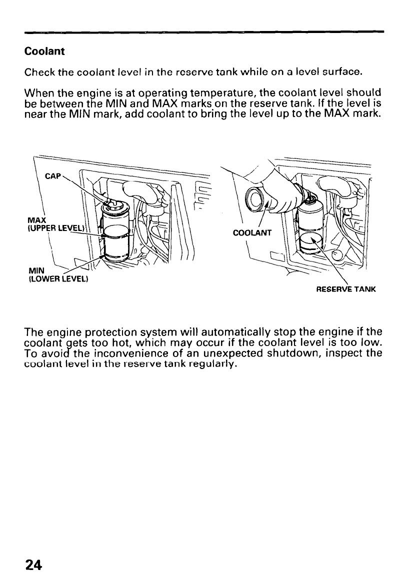
Coolant
Check the coolant level in the reserve tank while on a level surface.
When the en ine is at operating temperature, the coolant level should
be between t
ii e MIN and MAX marks on the reserve tank. If the level is
near the MIN mark, add coolant to bring the level up to the MAX mark.
(LOWER LEVEL)
RESERVE TANK
The engine protection system will automatically stop the engine if the
coolant ets too hot, which may occur if the coolant level is too low.
To avoi c7 the inconvenience of an unexpected shutdown, inspect the
coolant level in the reserve tank regularly.
24
If there is no coolant in the reserve tank:
Make sure the engine is cool, then check the coolant system for leaks
and have repairs made if needed. Add coolant to the radiator and
reserve tank before starting the engine.
Hot coolant is under pressure. If you remove the radiator cap when
the engine is hot, you may be scalded. Wait for the engine to cool.
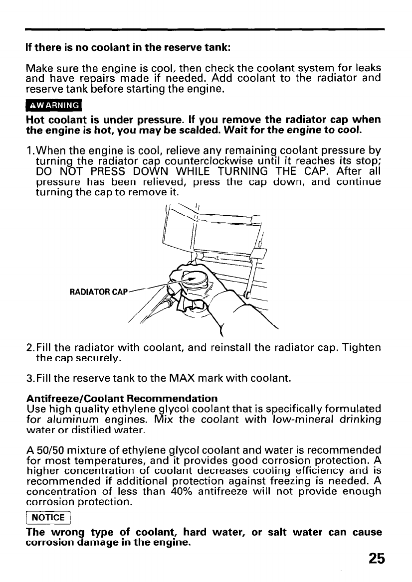
l.When the engine is cool, relieve any remaining coolant pressure by
turning the radiator cap counterclockwise until it reaches its stop;
DO NOT PRESS DOWN WHILE TURNING THE CAP. After all
pressure has been relieved, press the cap down, and continue
turning the cap to remove it.
1
RADIATOR CAP
2.Fill the radiator with coolant, and reinstall the radiator cap. Tighten
the cap securely.
3.Fill the reserve tank to the MAX mark with coolant.
Antifreeze/Coolant Recommendation
Use high quality ethylene lycol coolant that is specifically formulated
for aluminum engines. Iii ix the coolant with low-mineral drinking
water or distilled water.
A 50/50 mixture of ethylene glycol coolant and water is recommended
for most temperatures, and it provides good corrosion protection. A
higher concentration of coolant decreases cooling efficiency and is
recommended if additional protection against freezing is needed. A
concentration of less than 40% antifreeze will not provide enough
corrosion protection.
[I
The wrong type of coolant, hard water, or salt water can cause
corrosion damage in the engine.
25
STARTING THE ENGINE
Starting the engine’
1. Turn the fuel valve ON.
2. Make sure that the circuit breaker is OFF.
The generator may be hard to start if a load is connected.
3.Make sure the auto-throttle switch is off, or more time will be
required for warm up.
4.Turn the engine switch to START and hold it there until the engine
starts.
Do not use the electric starter for more than 5 seconds at a time. If
the engine fails to start, release the switch and wait 10 seconds
before operating the starter again.
When the speed of the starter motor drops after a period of time, it is
an indication that the battery should be recharged.
5. After the engine starts, let the engine switch return to ON.
6. Warm up the engine for 2-3 minutes. Turn the auto-throttle switch to
AUTO after the engine has warmed up.
26
Stopping the engine
In an emergency:
l.To stop the engine in an emergency, move the engine switch to the
OFF position.
In normal use:
1. Turn the AC circuit breaker to the OFF position.
2. Move the engine switch to the OFF position.
3. Turn the fuel valve to the OFF position.
27
MAINTENANCE
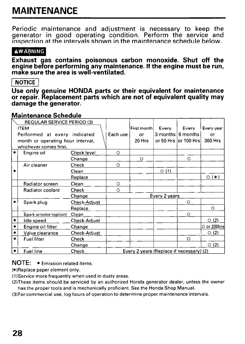
Periodic maintenance and adjustment is necessary to keep the
generator in good operating condition. Perform the service and
inspection at the intervals shown in the maintenance schedule below.
Exhaust gas contains poisonous carbon monoxide. Shut off the
engine before performing any maintenance. If the engine must be run,
make sure the area is well-ventilated.
p6iG-j
Use only genuine HONDA parts or their equivalent for maintenance
or repair. Replacement parts which are not of equivalent quality may
damage the generator.
Maintenance Schedule
NOTE: l Emission related items.
(*IReplace paper element only.
(1)Service more frequently when used in dusty areas.
(2)These items should be serviced by an authorized Honda generator dealer, unless the owner
has the proper tools and is mechanically proficient. See the Honda Shop Manual.
(3)For commercial use, log hours of operation to determine proper maintenance intervals.
28
Emission Control System
Source of Emissions
The combustion process produces carbon monoxide, oxides of
nitrogen, and hydrocarbons. Control of hydrocarbons and oxides of
nitrogen is very important because, under certain conditions, they
react to form photochemical smog when subjected to sunlight.
Carbon monoxide does not react in the same way, but it is toxic.
Honda Motor Co., Ltd, utilizes lean carburetor settings and other
systems to reduce the emissions of carbon monoxide, oxides of
nitrogen, and hydrocarbons.
The California Clean Air Act
California regulations require all manufacturers to furnish written in-
structions describing the operation and maintenance of emission
control systems. The following instructions and procedures must be
followed in order to keep the emissions from your Honda engine
within the emission standards.
Proper Maintenance is The Owner’s Responsibility
Replacement Parts
The emission control systems on your new Honda were designed,
built, and certified to conform with the California regulations. Honda
recommends only the use of new, genuine Honda parts or their
equivalent. The use of other replacement parts which are not of
equivalent quality may impair the effectiveness of your emission
control system.
Maintenance
Follow the maintenance schedule on page 28 . Remember that this
schedule is based on the assumption that your machine will be
used for its designed purpose. Sustained high-load or high-
temperature operation or use in unusually wet or dusty conditions
will require more frequent service.
Tampering and Altering
Tampering or altering the emission control system may increase
emissions beyond the legal limit. Among those acts presumed to
constitute tampering are:
l Removal or alteration of any part of the intake, fuel, or exhaust
systems.
l Altering or defeating the governor linkage or speed-adjusting
mechanism to cause the engine to operate outside its design
parameters.
Problems That Mav Affect Emissions
If you are aware of any of the following symptoms, have your
en ine inspected and repaired by your authorized Honda dealer:
l I? ard starting or stalling after starting.
l Rough idle.
l Misfiring or backfiring under load.
l After burning (backfiring).
l Black exhaust smoke or high fuel consumption.
29
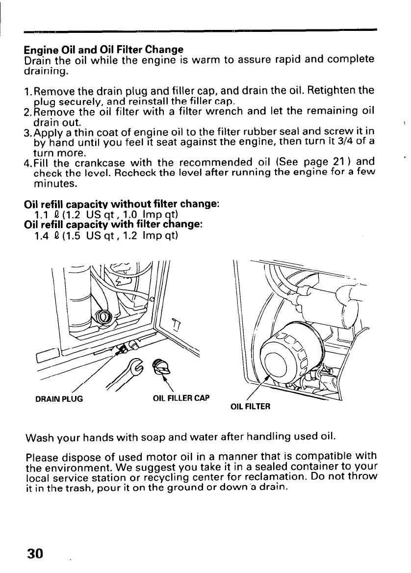
Engine Oil and Oil Filter Change
Drain the oil while the engine is warm to assure rapid and complete
draining.
1 .Remove the drain plug and filler cap, and drain the oil. Retighten the
plug securely, and reinstall the filler cap.
2.Remove the oil filter with a filter wrench and let the remaining oil
drain out.
3.Apply a thin coat of engine oil to the filter rubber seal and screw it in
by hand until you feel it seat against the engine, then turn It 3/4 of a
turn more.
4.Fill the crankcase with the recommended oil (See page 21 ) and
check the level. Recheck the level after running the engine for a few
minutes.
Oil refill capacity without filter change:
1.1 0 (1.2 US qt, 1.0 Imp t)
Oil refill capacity with filter c
R ange:
1.4 !.I (1.5 USqt, 1.2 Impqt)
OIL FILTER
Wash your hands with soap and water after handling used oil.
Please dispose of used motor oil in a manner that is compatible with
the environment. We suggest you take it in a sealed container to your
local service station or recycling center for reclamation. Do not throw
it in the trash, pour it on the ground or down ‘a drain.
30
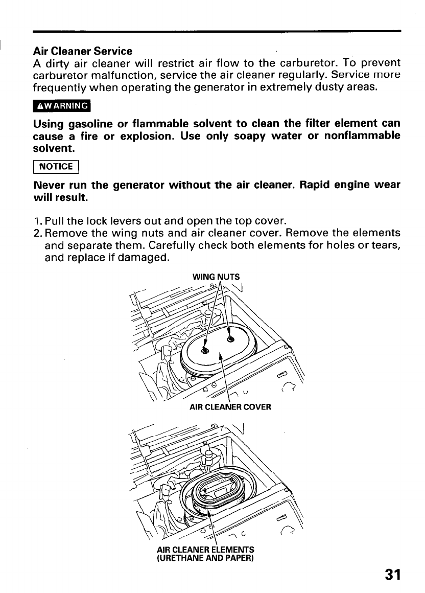
I Air Cleaner Service
A dirty air cleaner will restrict air flow to the carburetor. To prevent
carburetor malfunction, service the air cleaner regularly. Service more
frequently when operating the generator in extremely dusty areas.
Using gasoline or flammable solvent to clean the filter element can
cause a fire or explosion. Use only soapy water or nonflammable
solvent.
piieiq
Never run the generator without the air cleaner. Rapid engine wear
will result.
1. Pull the lock levers out and open the top cover.
2. Remove the wing nuts and air cleaner cover. Remove the elements
and separate them. Carefully check both elements for holes or tears,
and replace if damaged.
WING NUTS
, AIR CLEAbiER COVER
AIR CLEANER ELEMENTS
(URETHANE AND PAPER)
31
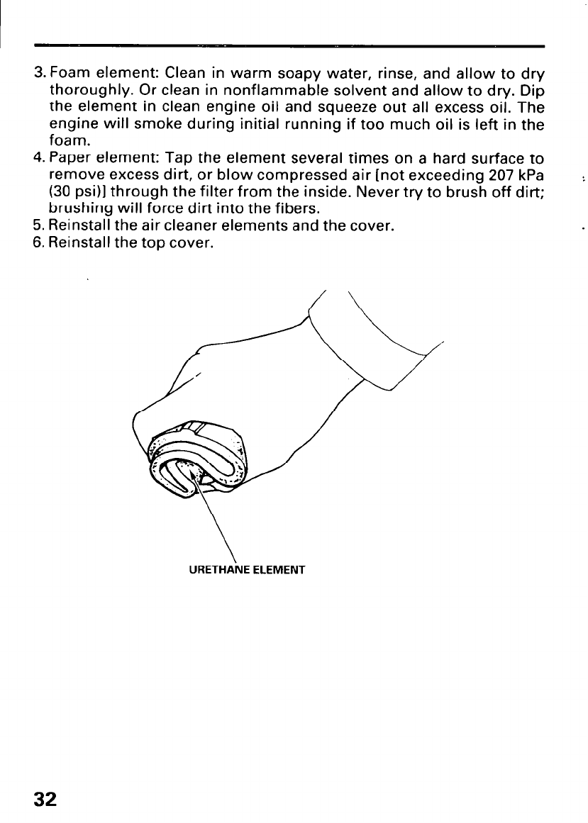
3. Foam element: Clean in warm soapy water, rinse, and allow to dry
thoroughly. Or clean in nonflammable solvent and allow to dry. Dip
the element in clean engine oil and squeeze out all excess oil. The
engine will smoke during initial running if too much oil is left in the
foam.
4. Paper element: Tap the element several times on a hard surface to
remove excess dirt, or blow compressed air [not exceeding 207 kPa
(30 psi)] through the filter from the inside. Never try to brush off dirt;
brushing will force dirt into the fibers.
5. Reinstall the air cleaner elements and the cover.
6. Reinstall the top cover.
URETHANE ELEMENT
32
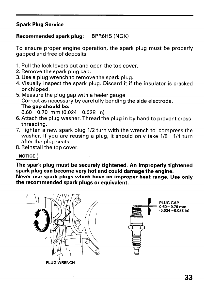
Spark Plug Service
Recommended spark plug: BPRGHS (NGK)
To ensure proper engine operation, the spark plug must be properly
gapped and free of deposits.
1. Pull the lock levers out and open the top cover.
2. Remove the spark plug cap.
3. Use a plug wrench to remove the spark plug.
4.Visually inspect the spark plug. Discard it if the insulator is cracked
or chipped.
5. Measure the plug gap with a feeler gauge.
Correct as necessary by carefully bending the side electrode.
The gap should be:
0.60-0.70 mm (0.024-0.028 in)
6. Attach the plug washer. Thread the plug in by hand to prevent cross-
threading.
7.Tighten a new spark plug l/2 turn with the wrench to compress the
washer. If you are reusing a plug, it should only take l/8-1/4 turn
after the plug seats.
8. Reinstall the top cover.
1 NOTICE 1
The spark plug must be securely tightened. An improperly tightened
spark plug can become very hot and could damage the engine.
Never use spark plugs which have an improper heat range. Use only
the recommended spark plugs or equivalent.
/
- PLUG GAP
0.60-0.70 mm
(0.024-0.028 in)
PLUG WRENCH
33
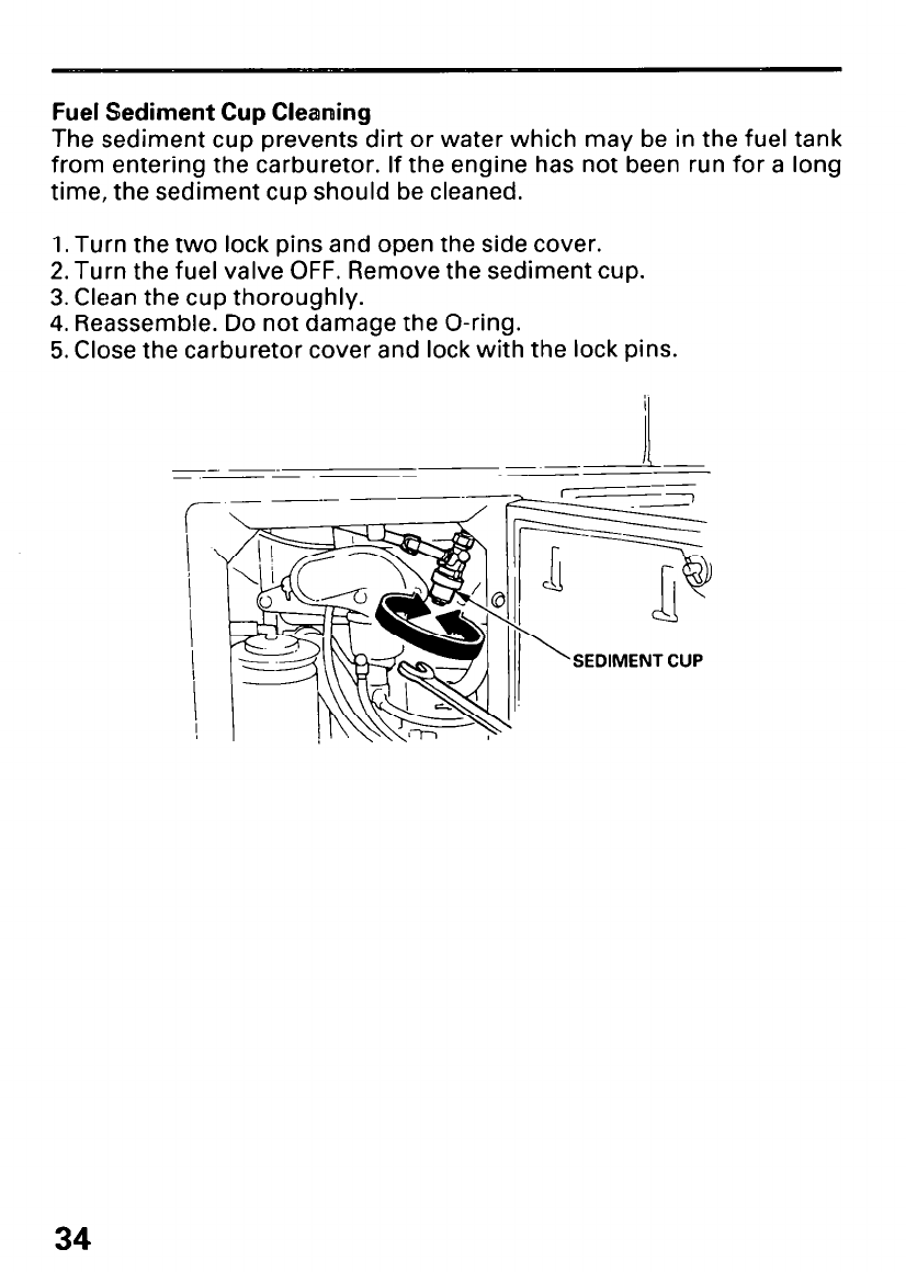
Fuel Sediment Cup Cleaning
The sediment cup prevents dirt or water which may be in the fuel tank
from entering the carburetor. If the engine has not been run for a long
time, the sediment cup should be cleaned.
1. Turn the two lock pins and open the side cover.
2. Turn the fuel valve OFF. Remove the sediment cup.
3. Clean the cup thoroughly.
4. Reassemble. Do not damage the O-ring.
5. Close the carburetor cover and lock with the lock pins.
SEDIMENT CUP
34
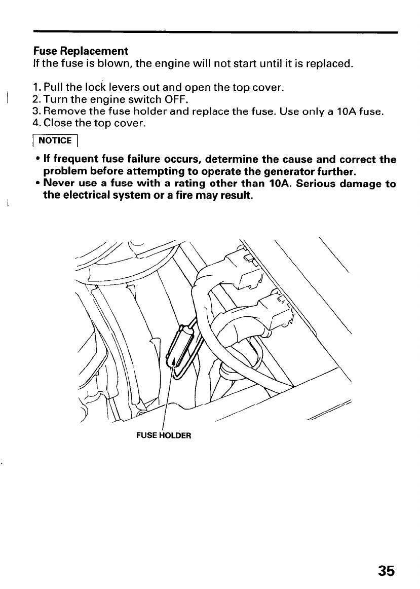
Fuse Replacement
If the fuse is blown, the engine will not start until it is replaced.
1. Pull the lock levers out and open the top cover.
2. Turn the engine switch OFF.
3. Remove the fuse holder and replace the fuse. Use only a IOA fuse.
4. Close the top cover.
1 NOTICE 1
l If frequent fuse failure occurs, determine the cause and correct the
problem before attempting to operate the generator further.
l Never use a fuse with a rating other than IOA. Serious damage to
/ the electrical system or a fire may result.
35
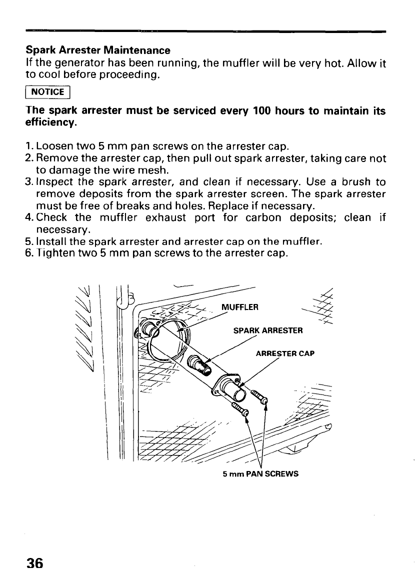
Spark Arrester Maintenance
If the generator has been running, the muffler will be very hot. Allow it
to cool before proceeding.
(1
The spark arrester must be serviced every 100 hours to maintain its
efficiency.
1. Loosen two 5 mm pan screws on the arrester cap.
2. Remove the arrester cap, then pull out spark arrester, taking care not
to damage the wire mesh.
3. Inspect the spark arrester, and clean if necessary. Use a brush to
remove deposits from the spark arrester screen. The spark arrester
must be free of breaks and holes. Replace if necessary.
4.Check the muffler exhaust port for carbon deposits; clean if
necessary.
5. Install the spark arrester and arrester cap on the muffler.
6. Tighten two 5 mm pan screws to the arrester cap.
5 mm PAN SCREWS
36
Battery
The generator’s engine has a 1 amp charging system to charge the
battery while the engine is running. If the generator is only. used
periodically, the battery must be charged monthly to maintain the
battery service life.
A lead acid battery self discharges at a rate of 0.5- 1 .O% per day. This
means that the battery, if the generator is not operated in a month,
can discharge as much as 30% in the same period. This could cause
the engine not to crank or shorten the service life of the battery. To
charge the battery, follow the procedures below.
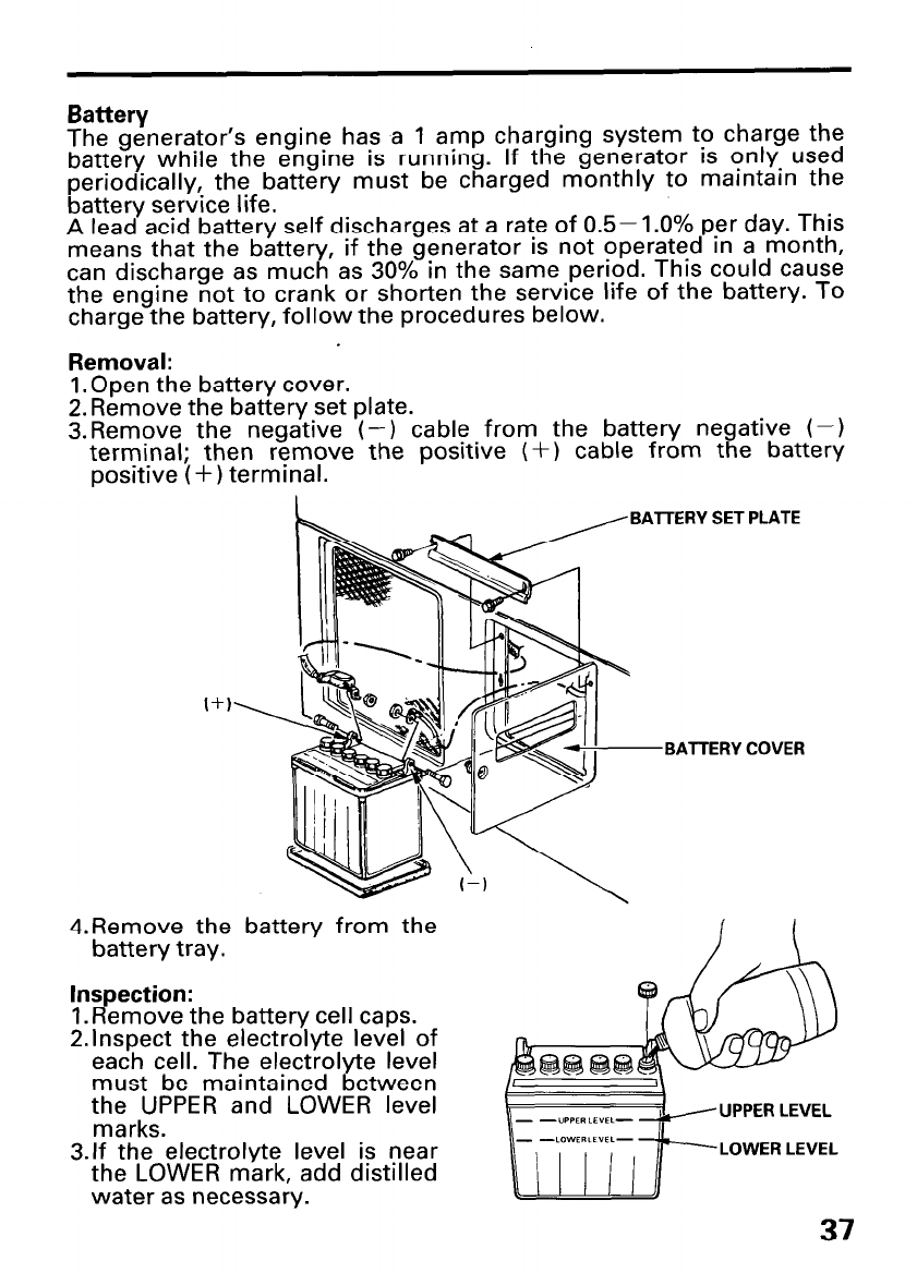
Removal:
1. Open the battery cover.
2. Remove the battery set plate.
3.Remove the negative (-1 cable from the battery negative (-)
terminal; then remove the positive (+) cable from the battery
positive (+) terminal.
. PLATE
BAlTERY SE1
BATTERY COVER
4.Remove the battery from the
battery tray.
Inspection:
1. Remove the battery cell caps.
2.lnspect the electrolyte level of
each cell. The electrolyte level
must be maintained between
the UPPER and LOWER level
marks. UPPER LEVEL
3.lf the electrolyte level is near
the LOWER mark, add distilled
water as necessary.
LOWER LEVEL
37
Charging:
The battery is rated at 14AH (ampere-hour). 10% of the ampere-hour
ratin 9
shou d should be used as the charging current. A battery charger
be used that can be adjusted to deliver 1.4 amps.
The battery gives off explosive gasses; keep sparks, flames and
cigarettes away from the battery while chargrng. Provide adequate
ventilation when charging.
l The battery contains sulfuric acid (electrolyte). Contact with skin or
eyes may cause severe burns. Wear protective clothing and a face
shield.
-If electrolyte gets on your skin, flush with water.
-If electrolyte gets in your eyes, flush with water for at least 15
minutes and call a physician immediately.
l Electrolyte is poisonous.
-If swallowed, drink large quantities of water or milk and follow
with milk of magnesia or ve etable oil and call a physician.
%
l KEEP OUT OF REACH OF CHIL REN.
1. Remove the battery cell caps.
2.Connect the battery charger following the manufacturer’s
instructions.
3.Charge the battery 3-4 hours.
4.After the battery is charged, inspect the electrolyte level in each of
the cells. Add distilled water as necessary.
5.lnstall the battery ca s.
6.Clean the outside o
P the battery and the battery tray compartment
with a solution of baking soda and water.
Installation:
1. Install the battery in the generator.
2.Install the positive (+) cable to the battery positive (+) terminal;
then install the negative (-) cable to the battery negative (-1
terminal.
3. Install the battery set plate.
4.Close and latch the battery cover.
38
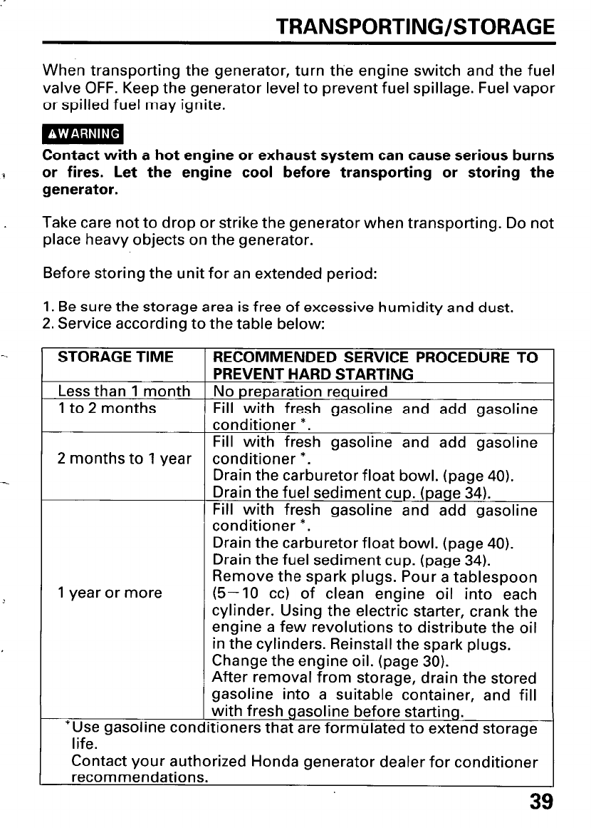
TRANSPORTING/STORAGE
When transporting the generator, turn the engine switch and the fuel
valve OFF. Keep the generator level to prevent fuel spillage. Fuel vapor
or spilled fuel may ignite.
Contact with a hot engine or exhaust system can cause serious burns
or fires. Let the engine cool before transporting or storing the
generator.
Take care not to drop or strike the generator when transporting. Do not
place heavy objects on the generator.
Before storing the unit for an extended period:
1. Be sure the storage area is free of excessive humidity and dust.
2. Service according to the table below:
STORAGE TIME
Less than 1 month
1 to 2 months
2 months to 1 year
1 year or more
*Use gasoline cone
life.
PREVENT HARD STARTING
No preparation required
Fill with fresh gasoline and add gasoline
conditioner *.
Fill with fresh gasoline and add qasoline
conditioner *. -
Drain the carburetor float bowl. (page 40).
Drain the fuel sediment cup. (page 34).
Fill with fresh gasoline and add gasoline
conditioner *.
Drain the carburetor float bowl. (page 40).
Drain the fuel sediment cup. (page 34).
Remove the spark plugs. Pour a tablespoon
(5-10 cc) of clean engine oil into each
cylinder. Using the electric starter, crank the
engine a few revolutions to distribute the oil
in the cylinders. Reinstall the spark plugs.
Change the engine oil. (page 30).
After removal from storage, drain the stored
gasoline into a suitable container, and fill
with fresh gasoline before starting.
tioners that are formulated to extend storage
Contact your authorized Honda generator dealer for conditioner
recommendations.
39
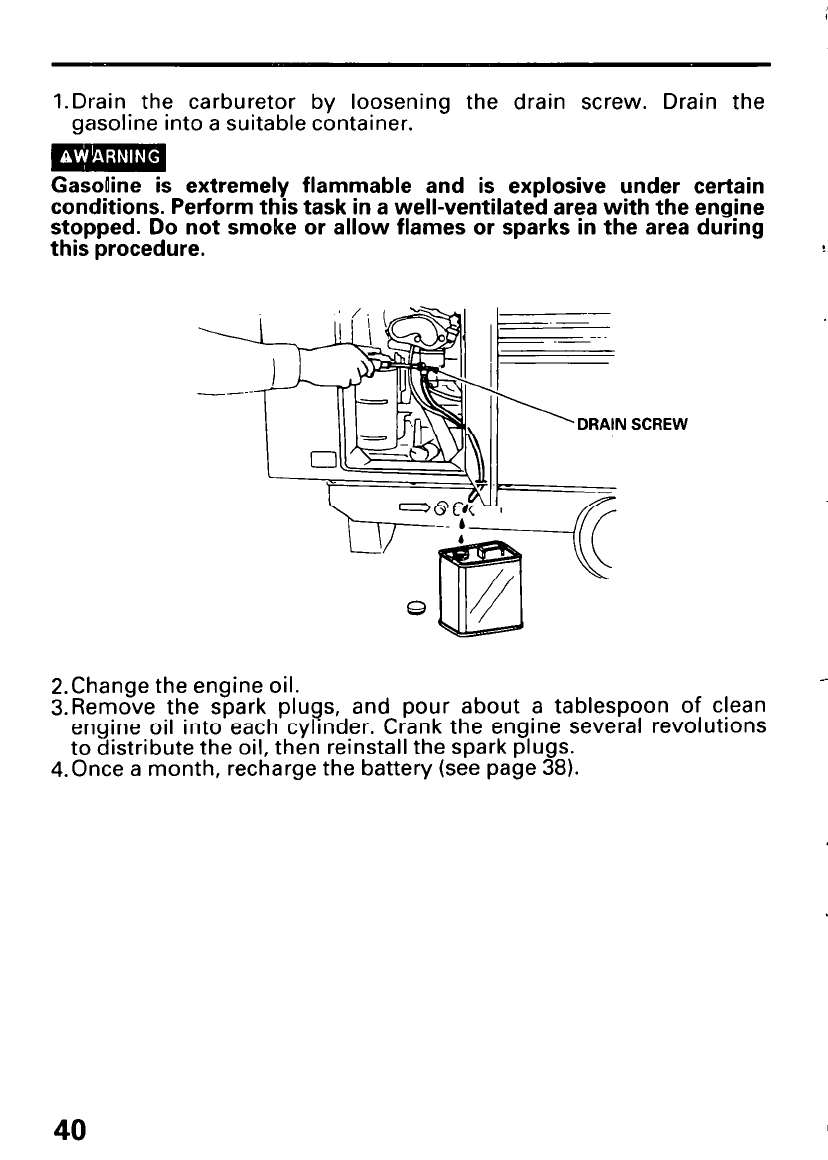
l.Drain the carburetor by loosening the drain screw. Drain the
gasoline into a suitable container.
Gasoline is extremely flammable and is explosive under certain
conditions. Perform this task in a well-ventilated area with the engine
stopped. Do not smoke or allow flames or sparks in the area during
this procedure.
SCREW
2.Change the engine oil.
3.Remove the spark plugs, and pour about a tablespoon of c!ean
engine oil into each cylrnder. Crank the engine several revolutrons
to distribute the oil, then reinstall the spark plugs.
4.Once a month, recharge the battery (see page 38).
40
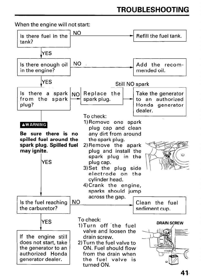
TROUBLESHOOTING
When the engine will not start:
Is there fuel in the NO b Refill the fuel tank.
tank?
Is there enough oil NO
in the engine?
I
~ Add the recom-
mended oil.
YES Still NO spark
Is there a spark NO Replace the Take the generator
from the spark - sparkplug. - to an authorized
plug? Honda generator
&
dealer.
To check:
1)Remove one spark
plug cap and clean
Be sure there is no any dirt from around
spilled fuel around the the spark plug.
spark plug. Spilled fuel 2)Remove the apark
may ignite.
I plug and install the
spark plug in the
YES plug cap.
3)Set the plug side
electrode on the
cylinder head.
4)Crank the engine,
sparks should jump
across the gap.
NO c Clean the fuel
sediment cup.
Is the fuel reaching
the carburetor?
If the engine still
does not start, take
the generator to an
authorized Honda
generator dealer.
To check:
lITurn off ‘the fuel DRAIN S/CREW
valve and loosen the
drain screw.
2)Turn the fuel valve to
ON. Fuel should flow
from the drain when
the fuel valve is
turned ON.
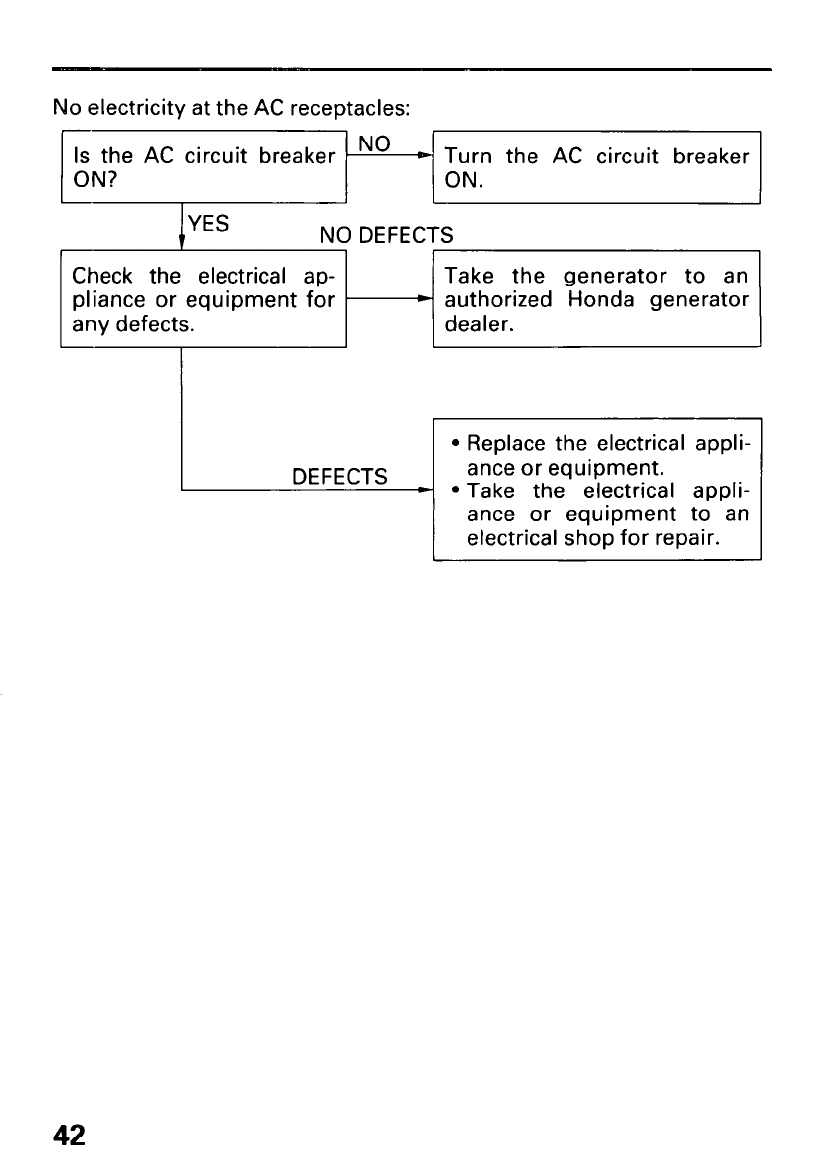
No electricity at the AC receptacles:
Is the AC circuit breaker No p Turn the AC circuit breaker
ON? ON.
YES NO DEFECTS
Check the electrical ap- Take the generator to an
pliance or equipment for * authorized Honda generator
any defects. dealer.
1 DEFECTS ~
l Replace the electrical appli-
ance or equipment.
l Take the electrical appli-
ance or equipment to an
electrical shop for repair.
42
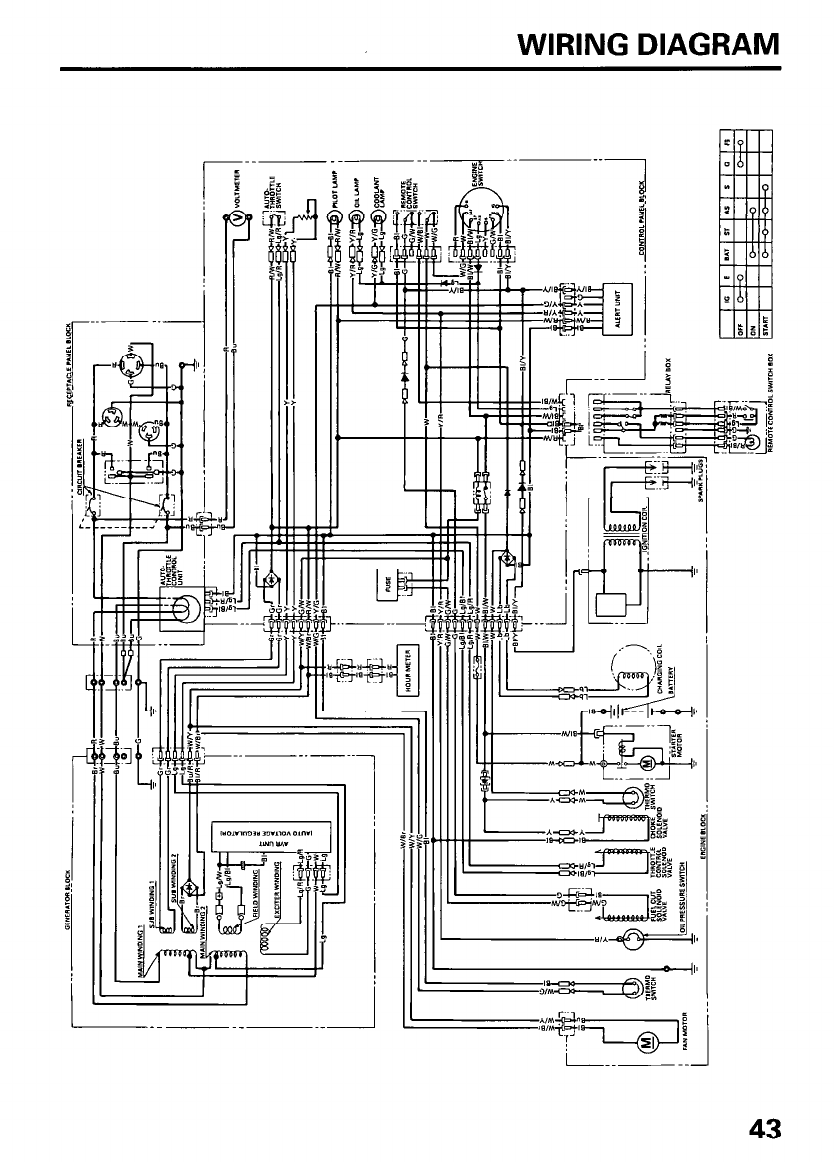
WIRING DIAGRAM
%PECIFICATIOM§
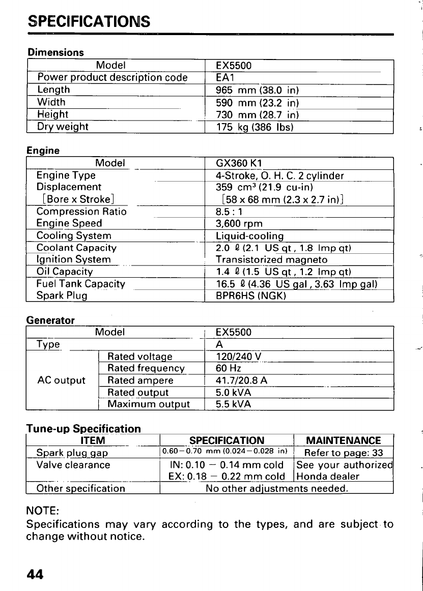
Dimensions
Model
Power product description code
Length
Width
Height
Dry weight -
EX5500
EAI
965 mm (38.0 in)
590 mm (23.2 in)
730 mm (28.7 in)
175 kg (386 Ibs)
Generator
Model i EX5500
~- . . .
Type A
--
-.-
Rated voltage 12OJ240 V
Rated frequency 60 Hz
AC output Rated ampere 1 41.7/20.8 A
Ratedoutput 1 5.0 kVA
Maximum output 1 5.5 kVA
Tune-up Specification
ITEM _ _ -.SPECIFICATION 1 MAINTENANCE
Spark. plug-gap 10.60-0.70 mm (0.024-0.028 in) ! Refer to page: 33
Valve clearance I
IN: 0.10 - 0.14 mm cold See your authorized
-.-I
.
EX: 6.18 - 0.22 mm cold Honda dealer
-. --
Other specification No other adjustments needed.
NOTE:
Specifications may vary according to the types, and are subject, to
change without notice.
INSTALLATION OF OPTIONAL PARTS
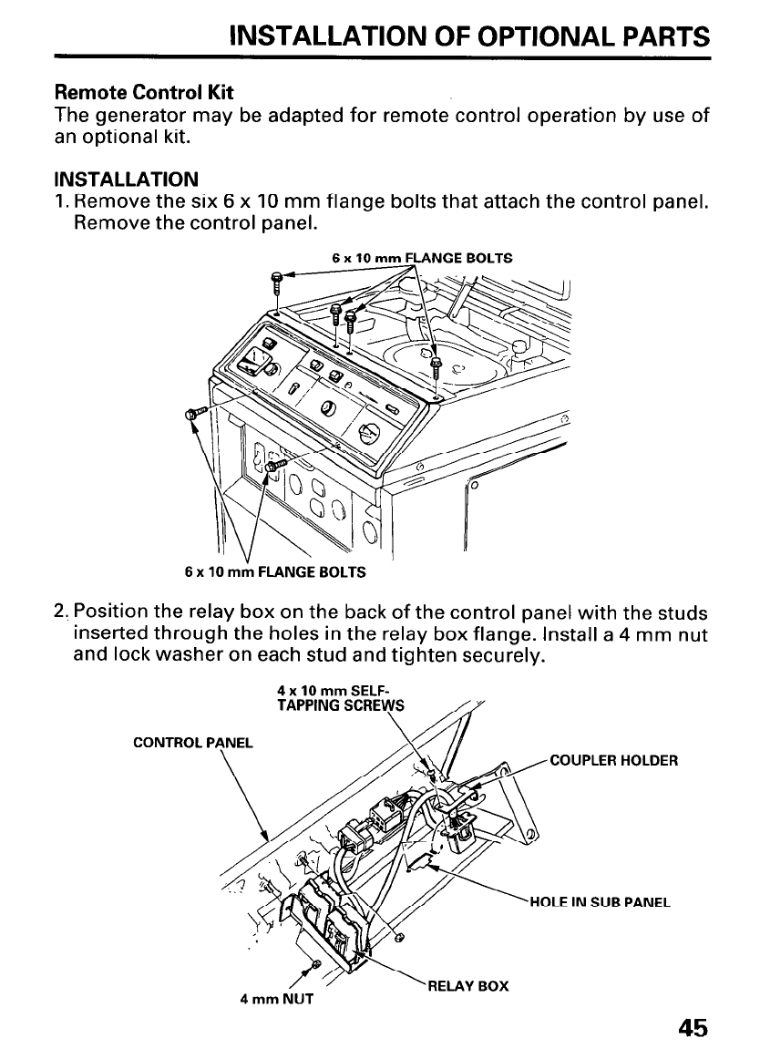
Remote Control Kit
The generator may be adapted for remote control operation by use of
an optional kit.
INSTALLATION
1. Remove the six 6 x 10 mm flange bolts that attach the control panel.
Remove the control panel.
6 x 10 mm FLANGE BOLTS
6 x 10 mtk FLANGE BOLTS
2. Position the relay box on the back of the control panel with the studs
inserted through the holes in the relay box flange. Install a 4 mm nut
and lock washer on each stud and tighten securely.
4 x 10 mm SELF-
TAPPING SCRE
CONTROL PANEL
COUPLER HOLDER
HOLE IN SUB PANEL
4 mm NUT
45
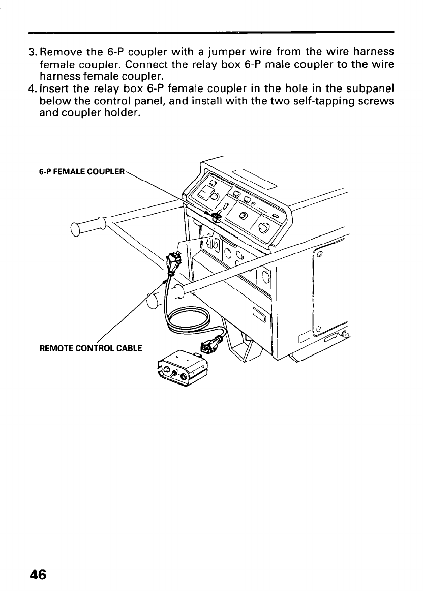
3. Remove the 6-P coupler with a jumper wire from the wire harness
female coupler. Connect the relay box 6-P male coupler to the wire
harness female coupler.
4. Insert the relay box 6-P female coupler in the hole in the subpanel
below the control panel, and install with the two self-tapping screws
and coupler holder.
6-P FEMALE COUPLER
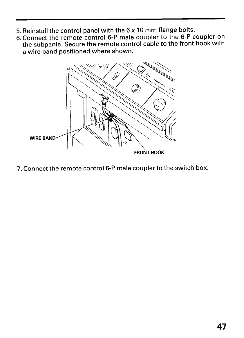
5. Reinstall the control panel with the 6 x 10 mm flange bolts.
6. Connect the remote control 6-P male coupler to the 6-P coupler on
the subpanle. Secure the remote control cable to the front hook with
a wire band positioned where shown.
WIRE BAND
FROiT HOOK
7. Connect the remote control 6-P male coupler to the switch box.
47
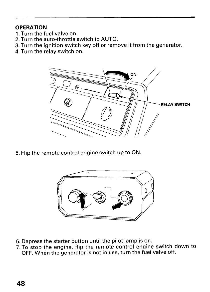
OPERATION
1. Turn the fuel valve on.
2. Turn the auto-throttle switch to AUTO.
3. Turn the ignition switch key off or remove it from the generator.
4. Turn the relay switch on.
RELAY SWITCH
5. Flip the remote control engine switch up to ON.
6. Depress the starter button until the pilot lamp is on.
7.To stop the engine, flip the remote control engine switch down to
OFF. When the generator is not in use, turn the fuel valve off.
.-
CUSTOMER SERVICE INFORMATION
Honda power equipment dealership personnel are trained
professionals. They should be able to answer any question you may
have. If you encounter a problem that your dealer does not solve to
your satisfaction, please discuss it with the dealership’s management.
The Service Manager or General Manager can help. Almost all
problems are solved in this way.
If you are dissatisfied with the decision made by the dealership’s
management, contact the Honda Power Equipment Customer Service
Office. You can write to:
American Honda Motor Co., Inc.
Honda Power Equipment Division
Customer Service Office
4475 River Green Parkway
Duluth, Georgia 30136-2565
Or telephone: (404) 497-6400
When you write or call, please give us this information:
l Model and serial number (see pages 8 and 9 1
l Name of dealer who sold the generator to you
l Name and address of dealer who services your generator
l Date of purchase
l Your name, address, and telephone number
l A detailed description of the problem
49
Current customer service contact information:
United States, Puerto Rico, and U.S. Virgin Islands:
Honda Power Equipment dealership personnel are trained professionals. They should
be able to answer any question you may have. If you encounter a problem that your
dealer does not solve to your satisfaction, please discuss it with the dealership's
management. The Service Manager or General Manager can help. Almost all problems
are solved in this way.
If you are dissatisfied with the decision made by the dealership's management, contact
the Honda Power Equipment Customer Relations Office. You can write:
American Honda Motor Co., Inc.
Power Equipment Division
Customer Relations Office
4900 Marconi Drive
Alpharetta, GA 30005-8847
Or telephone: (770) 497-6400 M-F, 8:30 am - 7:00 pm EST
When you write or call, please provide the following information:
• Model and serial numbers
• Name of the dealer who sold the Honda power equipment to you
• Name and address of the dealer who services your equipment
• Date of purchase
• Your name, address, and telephone number
• A detailed description of the problem
UUWEX
COMPONENT IDENTIFICATION ............................................................... 8
CONTROLS ............................................................................................... 10
Auto-throttle System ......................................................................... 13
Circuit Breaker .................................................................................... 10
Engine Switch ..................................................................................... 10
Fuel Valve ........................................................................................... 11
Ground Terminal ................................................................................ 11
Oil Pressure Lamp .............................................................................. 14
Pilot Lamp ........................................................................................... 13
Voltage Adjustment Knob ................................................................. 12
Voltmeter ............................................................................................ 12
CUSTOMER SERVICE INFORMATION ................................................... 49
GENERATOR USE .................................................................................... 15
AC Applications .................................................................................. 16
AC Operation ...................................................................................... 17
AC Receptacle Selection .................................................................... 18
Auto-throttle System ......................................................................... 19
Connections to a Building’s Electrical System ................................ 15
Ground System .................................................................................. 15
High Altitude Operation ..................................................................... 20
Special Requirements ........................................................................ 15
INDEX ....................................................................................................... 50
INSTALLATION OF OPTIONAL PARTS .................................................. 45
MAINTENANCE ....................................................................................... 28
Air Cleaner Service ............................................................................ 30
Battery ................................................................................................. 36
Emission Control System .................................................................. 29
Engine Oil and Oil Filter Change ....................................................... 30
Fuel Sediment Cup Cleaning ............................................................ 34
Fuse Replacement .............................................................................. 35
Maintenance Schedule ...................................................................... 28
Spark Arrester Maintenance ............................................................. 36
Spark Plug Service ............................................................................. 33
50
PRE-OPERATION CHECK ........................................................................ 21
Engine Oil ........................................................................................... 21
Coolant ................................................................................................ 24
Fuel Recommendation ...................................................................... 22
SAFETY ....................................................................................................... 4
Safety Information ............................................................................... 6
Safety Label Locations ........................................................................ 4
SPECIFICATIONS ..................................................................................... 44
STARTING THE ENGINE ......................................................................... 26
STOPPING THE ENGINE ......................................................................... 27
TRANSPORTING/STORAGE ................................................................... 39
TROUBLESHOOTING .............................................................................. 41
WIRING DIAGRAM .................................................................................. 43
51

MEMO
52