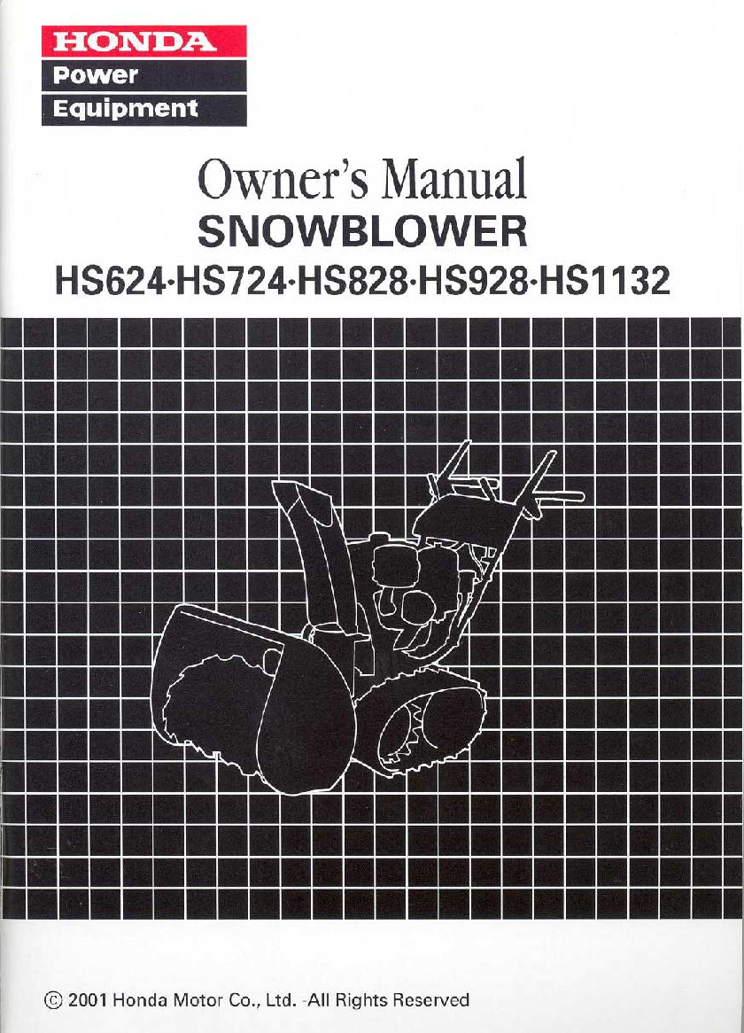
Honda Hs724 Users Manual
2015-03-12
: Honda Honda-Hs724-Users-Manual-657410 honda-hs724-users-manual-657410 honda pdf
Open the PDF directly: View PDF ![]() .
.
Page Count: 81
- COVER
- INTRODUCTION
- CONTENTS
- SNOWBLOWER SAFETY
- CONTROLS & FEATURES
- BEFORE OPERATION
- OPERATION
- SERVICING YOUR HONDA SNOWBLOWER
- THE IMPORTANCE OF MAINTENANCE
- MAINTENANCE SAFETY
- TOOL KIT
- MAINTENANCE SCHEDULE
- REFUELING
- FUEL RECOMMENDATIONS
- ENGINE OIL LEVEL CHECK
- ENGINE OIL CHANGE
- ENGINE OIL RECOMMENDATIONS
- HYDROSTATIC TRANSMISSION OIL
- SPARK PLUG SERVICE
- TRACK ADJUSTMENT
- TIRE INSPECTION
- AUGER AND BLOWER INSPECTION
- SHEAR BOLT REPLACEMENT PROCEDUR
- SKID SHOES AND SCRAPER
- STORAGE
- TRANSPORTING
- TAKING CARE OF UNEXPECTED PROBL
- TECHNICAL & CONSUMER INFORMATION
- QUICK REFERENCE INFORMATION
The engine exhaust from this product
contains chemicals known to the State of
California to cause cancer, birth defects,
or other reproductive harm.
Keep this owner’s manual handy,
so
you can refer to it any time.
This owner’s manual is considered a permanent part of the snowblower and
should remain with the snowblower if resold.
The information and specifications included in this publication were in effect
at the time of approval for printing. Honda Motor Co., Ltd. reserves the right,
however, to discontinue or change specifications or design at any time with-
out notice and without incurring any obligation whatever.
Congratulations on your selection of a Hondasnowblower. We are certain you
will be pleased with your purchase of one of the finest snowblowers on the
market.
We want to help you get the best results from your new snowblower and to
operate it safely. This manual contains the information on how to do that;
please read it carefully.
As
you read this manual, you will find information preceded by a
symbol. That information is intended to help you avoid damage to your
snowbrower, other property, or the environment.
We suggest you read the warranty policy to fully understand its coverage and
your responsibilities of ownership. The warranty policy is a separate document
that should have been given to you by your dealer.
When your snowblower needs scheduled maintenance, keep in mind that
your Honda servicing dealer is specially trained in servicing Honda
snowblowers. Your Honda servicing dealer is dedicated to your satisfaction
and will be pleased to answer your questions and concerns.
Best Wishes,
Honda Motor Co., Ltd.
1
INTRODUCTION
A
FEW WORDS ABOUT SAFETY
Your safety and the safety of others are very important. And using this
snowblower safely is an important responsibility.
To help you make informed decisions about safety, we have provided
operating procedures and other information on labels and in this manual.
This information alerts you to potential hazards that could hurt you or others.
Of course, it is not practical or possible to warn you about all the hazards
associated with operating or maintaining a snowblower. You must use your
own good judgment.
You will find important safety information in a variety of forms, including:
Safety Labels
-
on the snowblower.
0
Safety Messages-
preceded by a safety alert symbol
A
and one of three
signal words: DANGER, WARNING, or CAUTION.
These signal words mean:
You WILL be KILLED
or
SERIOUSLY
HURT
if
you don’t follow instructions.
You CAN be KILLED or SERIOUSLY
HURT
if
you don’t follow instructions.
You CAN be HURT
i
follow instructions.
f
you don’t
Safety Headings
-
such as
IMPORTANT SAFETY INFORMATION.
Safety Section
-
such as
SNOWBLOWER SAFETY.
0
Instructions
-
how to use this snowblower correctly and safely.
This entire book is filled with important safety information
-
please read it
carefully.
2
SNOWBLOWER SAFETY
..........................................................................
5
IMPORTANT SAFETY INFORMATION
.................................................
5
SAFETY LABEL LOCATIONS
...............................................................
8
CONTROLS
&
FEATURES
........................................................................
9
COMPONENT
&
CONTROL LOCATIONS
............................................
9
CONTROLS
.........................................................................................
11
Fuel Valve Lever
.............................................................................
11
Engine Switch
..................................................................................
11
Fuel Gauge
......................................................................................
11
Chute Crank
....................................................................................
12
Starter Grip
......................................................................................
12
Throttle Lever
..................................................................................
12
Choke Knob
.....................................................................................
13
Shift Lever
.......................................................................................
13
Discharge Deflector Lever
...............................................................
14
Foot Pedal
.......................................................................................
14
Drive Clutch Lever and Auger Clutch Lever
....................................
15
Transmission Release Lever
...........................................................
16
FEATURES
..........................................................................................
17
Work Light
.......................................................................................
17
Snow Clearing Bar
..........................................................................
17
BEFORE OPERATION
.............................................................................
18
ARE YOU READY TO GET STARTED?
.............................................
18
IS
YOUR SNOWBLOWER READY TO GO?
.......................................
18
Check the General Condition
of
the Snowblower
............................
19
Check the Engine
............................................................................
19
CHECK YOUR WORK AREA
..............................................................
20
OPERATION
.............................................................................................
21
SNOWBLOWING PRECAUTIONS
......................................................
21
STARTING THE ENGINE
....................................................................
21
STOPPING THE ENGINE
....................................................................
26
CLEARING SNOW
...............................................................................
29
SNOW-CLEARING TIPS
.....................................................................
32
REMOVING OBSTRUCTIONS
............................................................
33
SERVICING
YOUR
HONDA SNOWBLOWER
.........................................
34
THE IMPORTANCE OF MAINTENANCE
............................................
34
MAINTENANCE SAFETY
....................................................................
35
TOOL KIT
.............................................................................................
36
MAINTENANCE SCHEDULE
..............................................................
37
REFUELING
.........................................................................................
38
FUEL RECOMMENDATIONS
..............................................................
39
3
SERVICING YOUR HONDA SNOWBLOWER (continued)
ENGINE OIL LEVEL CHECK
...............................................................
40
ENGINE OIL CHANGE
........................................................................
41
ENGINE OIL RECOMMENDATIONS
..................................................
42
HYDROSTATIC TRANSMISSION OIL
................................................
43
SPARK PLUG SERVICE
.....................................................................
45
TRACK ADJUSTMENT
........................................................................
47
TIRE INSPECTION
..............................................................................
48
AUGER AND BLOWER INSPECTION
................................................
48
SHEAR BOLT REPLACEMENT PROCEDURE
..................................
49
SKID SHOES AND SCRAPER
............................................................
50
STORAGE
................................................................................................
52
STORAGE PREPARATION
.................................................................
52
Cleaning
..........................................................................................
52
Fuel
.................................................................................................
53
Engine Oil
........................................................................................
56
Tires
................................................................................................
56
STORAGE PRECAUTIONS
.................................................................
57
REMOVAL FROM STORAGE
.............................................................
57
TRANSPORTING
.....................................................................................
58
TAKING CARE OF UNEXPECTED PROBLEMS
....................................
60
ENGINE PROBLEMS
..........................................................................
60
Engine Will Not Start
.......................................................................
60
Engine Lacks Power
........................................................................
61
DRIVE PROBLEMS
.............................................................................
62
Snowblower Does Not Move
...........................................................
62
SNOWBLOWER PROBLEMS
.............................................................
63
Snowblower Does Not Operate
.......................................................
63
TECHNICAL INFORMATION
...............................................................
65
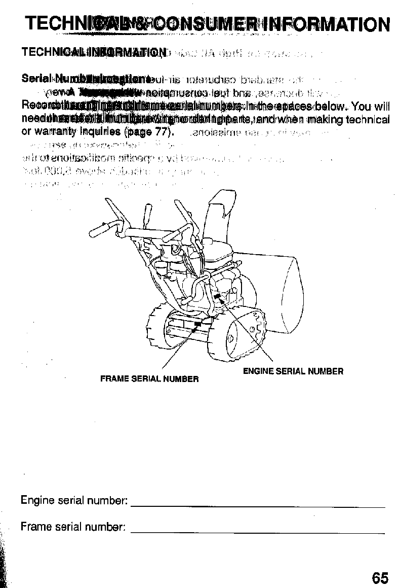
Serial Number Locations
.................................................................
65
Carburetor Modification for High Altitude Operation
........................
66
Oxygenated Fuels
...........................................................................
67
Emission Control System Information
.............................................
68
Air Index
..........................................................................................
70
Specifications
..................................................................................
71
CONSUMER INFORMATION
..............................................................
76
Honda Publications
.........................................................................
76
Warranty Service Information
..........................................................
77
QUICK REFERENCE INFORMATION
..........................
Inside back cover
TECHNICAL
&
CONSUMER INFORMATION
.........................................
65
SNOWBLOWER
SAFETY
IMPORTANT SAFETY INFORMATION
Hondasnowblowers are designed to clear snow from driveways and walkways.
Other uses can result in injury to the operator or damage to the snowblower
and other property.
Most accidents with snowblowers can be prevented
if
you follow all instructions
in this manual and on the snowblower. The most common hazards, according
accident statistics, are discussed below, along with the best way to protect
yourself and others.
Avoid Rotating Auger
The snowblower auger can cause serious cuts and even amputate fingers,
hands, toes, or feet. Keep away from the auger whenever the engine is
running.
If
you need to work around the snowblower to clear snow for any
reason, always shut off the engine.
If
the snow discharge chute becomes
clogged, stop the engine and disconnect the spark plug cap. Use the snow
clearing bar or a wooden stick to remove the obstruction. Never put your hand
into the snow discharge chute while the engine is running; serious personal
injury could result.
Clear Operation Area
The snowblower can throw rocks and other objects with enough force to cause
serious injury. Before operating the snowblower, carefully inspect the area
and remove all stones, sticks, bones, nails, pieces of wire, and other loose
objects. Never use the snowblower to clear snow from a gravel road or
driveway, as rocks may be picked up and ejected. They may cause injury to
bystanders.
5
SNOWBLOWER
SAFETY
Keep Shields in Place
Guards and shields are designed to protect you from being hit by thrown
objectsand to keep you from touching hot engine parts and moving components.
For your safety and the safety of others, keep all shields in place when the
engine is running.
Adjust the snow discharge chute to avoid hitting the operator, bystanders,
windows, and other objects with ejected snow. Stay clear of the snow
discharge chute while the engine is running.
Children and pets must be kept away from the area of operation to avoid injury
from flying debris and contact with the snowblower.
Refuel with Care
Gasoline
is
extremely flammable, and gasoline vapor can explode.
Allow
the
engine to cool if the snowblower has been in operation. Refuel only outdoors
in
a
well-ventilated area with the engine
OFF.
Never
fill
the fuel tank beyond
the maximum fill mark. Never smoke near gasoline, and keepother flames and
sparks away. Always store gasoline in an approved container.
Turn Engine
OFF
When Not Operating the Snowblower
If
you need to leave the snowblower for any reason, even just to inspect the
area ahead, always turn the engine
off.
Operation on Slopes
To
avoid overturning, be careful when changing the direction of the snowblower
while operating it on a slope.
Do
not use the snowblower
to
remove snow from
roofs. The snowblower may overturn on steep slopes if left unattended
causing injury to the operator
or
bystanders.
6
SNOWBLOWER SAFETY
Operating Conditions
Do
not use the snowblower when visibility is poor. Under conditions of poor
visibility, there is a greater risk of striking an obstacle or causing injury. Adjust
the snow discharge chute to avoid hitting passing bystanders or vehicles. Stay
clear of the snow discharge chute while the engine is running.
Operating Near Roads
Always watch for vehicle traffic when operating the snowblower near roads
and driveways. Never operate the snowblower on public roads.
Operator Responsibility
Know how to stop the snowblower quickly in case of emergency. Understand
the use of all snowblower controls.
Never permit anyone to operate the snowblower without proper instruction.
Do
not let children operate the snowblower.
If
people or pets suddenly appear
in front of the snowblower while it is in operation, immediately release the
auger and drive clutch levers to stop the snowblower and avoid possible injury
from rotating auger blades.
While operating the snowblower, hold the handle firmly, and walk, don't run.
Wear suitable winter boots that resist slipping.
7

SNOWBLOWER
SAFETY
SAFETY LABEL LOCATIONS
These labels warn you of potential hazards that can cause serious injury. Read
them carefully.
If
a label comes
off
or becomes hard to read, contact your
Honda snowblower dealer for a replacement.
AWARNING
1
OF
DISCHARGE
KEEP
HANDS
OU1
CHUTE WHILE
BGASOLINE
IS
FLAM-
USHUT
OFF ENGINE
WHEN REFUELING.
UNEVER REFUEL
IO0
NOT
OVERFILL.
8
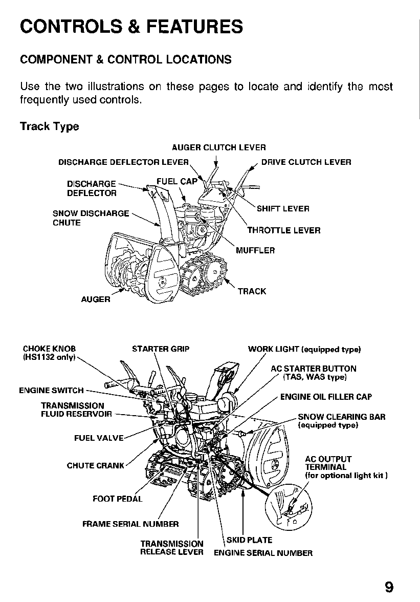
CONTROLS
&
FEATURES
COMPONENT
&
CONTROL LOCATIONS
Use the two illustrations on these pages to locate and ider
frequently used controls. ltify
Track
Type
AUGER CLUTCH LEVER
DISCHARGE DEFLECTOR LEVER DRIVE CLUTCH LEVER
DEFLECTOR
SNOW
DISCHARGE
CHUTE
SHIFT
LEVER
THROlTLE LEVER
the most
CHOKE KNOB STARTER GRIP
(HS1132
only),
-\
WORK LIGHT
(equipped type)
m
AC STARTER BUlTON
(TAS, WAS
type)
ENGINE OIL FILLER CAP
ENGINE SWITCH
TRANSMISSION
FLUID RESERVOIR
FUEL VALVE
CHUTE CRANK
SNOW CLEARING BAR
(equipped type)
TERMINAL
AC OUTPUT
(for
optional light kit
)
FOOTPEDA/L
/
P
-\
1
FRAME SERIAL NUMBER
TRANSMISSION
\SKID
PLATE
RELEASE LEVER ENGINE SERIAL NUMBER
9
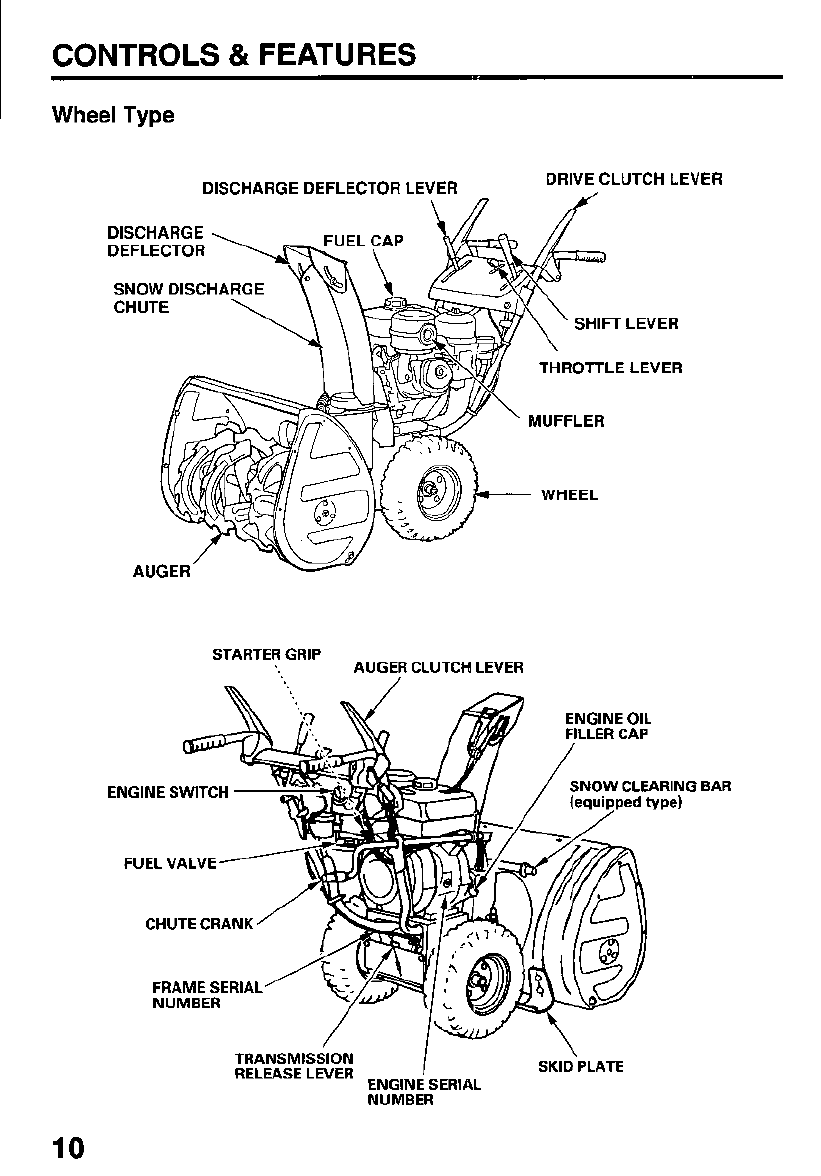
CONTROLS
&
FEATURES
Wheel
Type
DISCHARGE DEFLECTOR LEVER DRIVE CLUTCH LEVER
DEFLECTOR
SNOW
DISCHA
SHIFT LEVER
STARTER GRIP AUGER CLUTCH LEVER
ENGINE SWITCH
FUEL VALVE
CHUTE CRANK
FRAME SERIAL
BAR
TRANSMISSION
RELEASE LEVER
I
\
SKID
PLATE
ENGINE SERIAL
NUMBER
10
CONTROLS
&
FEATURES
~~~
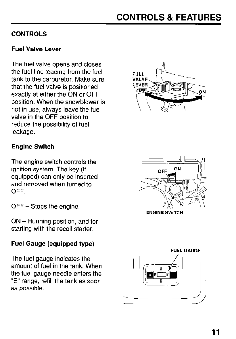
CONTROLS
Fuel Valve Lever
The fuel valve opens and closes
the fuel line leading from the fuel
tank to the carburetor. Make sure
that the fuel valve is positioned
exactly at either the
ON
or
OFF
position. When the snowblower is
not in use, always leave the fuel
valve in the
OFF
position
to
reduce the possibility
of
fuel
leakage.
Engine Switch
The engine switch controls the
ignition system. The key (if
equipped) can only be inserted
and removed when turned to
OFF.
OFF
-
Stops the engine.
FUEL
k
ENGINE
SWITCH
ON
-
Running position, and for
starting with the recoil starter.
Fuel Gauge (equipped type)
FUEL GAUGE
The fuel gauge indicates the
amount of fuel in the tank. When
the fuel gauge needle enters the
"E"
range, refill the tank as soon
as
possible.
/I
JI
11
CONTROLS
&
FEATURES
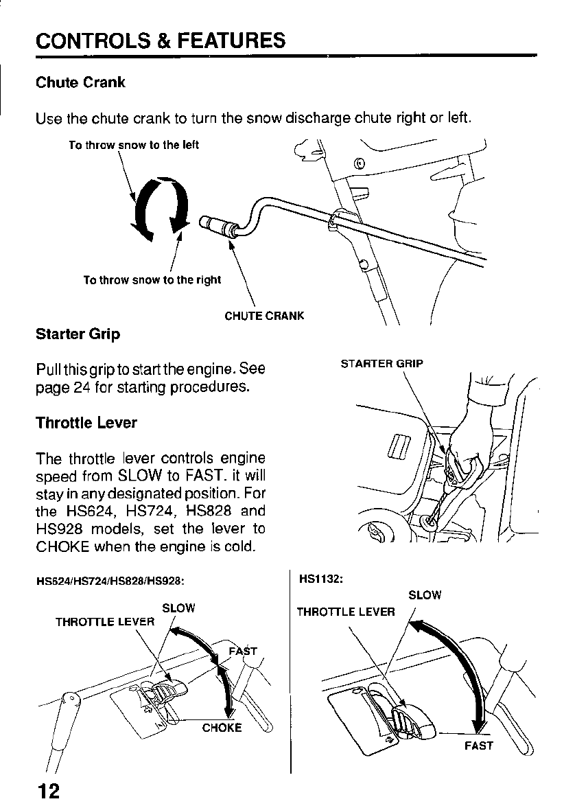
Chute Crank
Use the chute crank to turn the snow discharge chute right or left.
To throw snow to the left
kJ
I
To
throw snow to the right
Starter Grip
Pull this grip to start the engine. See
page 24 for starting procedures.
Throttle Lever
The throttle lever controls engine
speed from
SLOW
to
FAST.
it will
stay in any designated position. For
the HS624, HS724, HS828 and
HS928 models, set the lever to
CHOKE when the engine is cold.
SLOW
M
12
STARTER
GRIP
HS1132:
SLOW
THROlTLE LEVER
/
THROTTLE LE
CONTROLS
&
FEATURES
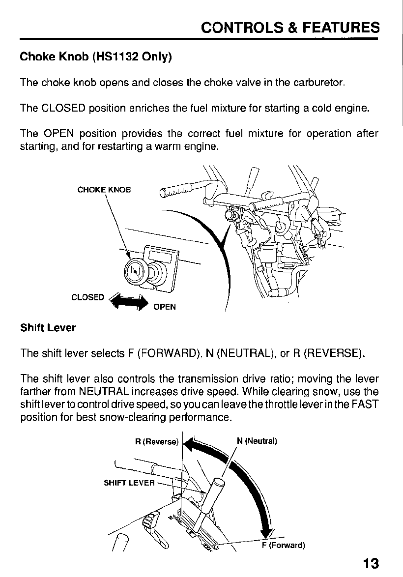
Choke
Knob
(HS1132
Only)
The choke knob opens and closes the choke valve in the carburetor.
The CLOSED position enriches the fuel mixture for starting a cold engine.
The OPEN position provides the correct fuel mixture for operation after
starting, and for restarting a warm engine.
Shift
Lever
The shift lever selects F (FORWARD), N (NEUTRAL), or R (REVERSE).
The shift lever also controls the transmission drive ratio; moving the lever
farther from NEUTRAL increases drive speed. While clearing snow, use the
shift lever to control drive speed,
so
you can leave the throttle lever in the FAST
position for best snow-clearing performance.
13
CONTROLS & FEATURES
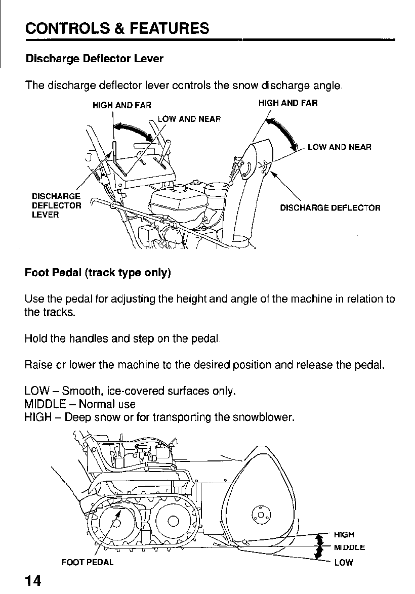
Discharge Deflector Lever
The discharge deflector lever controls the snow discharge angle.
HIGH AND FAR HIGH AND FAR
/
DISCHARGE
DEFLECTOR
LEVER
Foot Pedal (track type only)
Use the pedal for adjusting the height and angle of the machine in relation to
the tracks.
Hold the handles and step on the pedal.
Raise or lower the machine to the desired position and release the pedal.
LOW
-
Smooth, ice-covered surfaces only.
MIDDLE
-
Normal use
HIGH
-
Deep snow or for transporting the snowblower.
HIGH
MIDDLE
LOW
14
CONTROLS
&
FEATURES
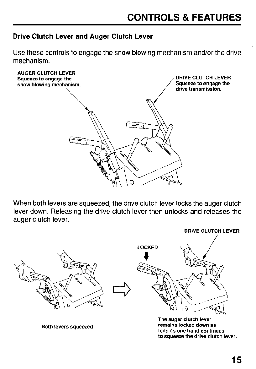
Drive Clutch Lever
and
Auger Clutch Lever
Use these controls to engage the snow blowing mechanism and/or the drive
mechanism.
AUGER
CLUTCH
LEVER
Squeeze to engage the
DRIVE
CLUTCH
LEVER
snow blowing mechanism. Squeeze
to
engage the
drive transmission.
When both levers are squeezed, the drive clutch lever locks the auger clutch
lever down. Releasing the drive clutch lever then unlocks and releases the
auger clutch lever.
DRIVE
CLUTCH
LEVER
Both levers squeezed
The auger clutch lever
remains locked down as
long as one hand continues
to squeeze the drive clutch lever.
15
CONTROLS
81
FEATURES
Transmission
Release
Lever
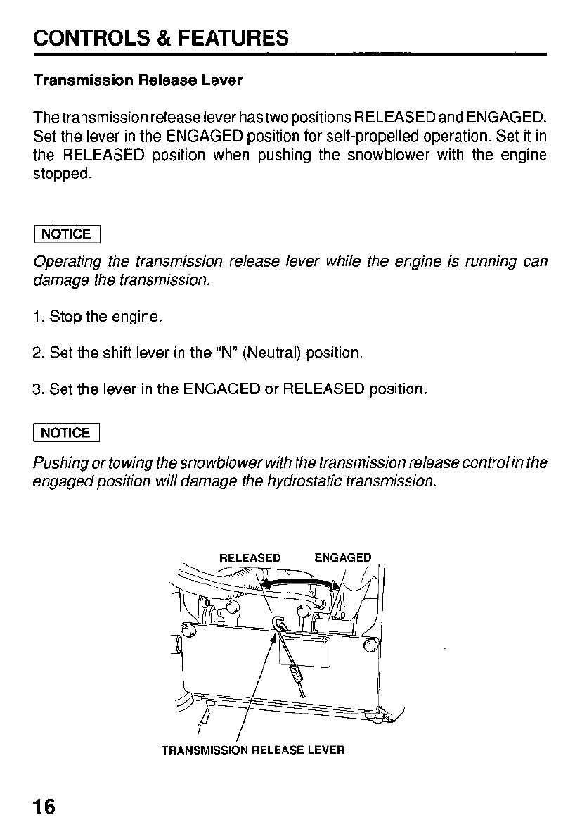
The transmission release lever has two positions RELEASED and ENGAGED.
Set the lever in the ENGAGED position for self-propelled operation. Set it in
the RELEASED position when pushing the snowblower with the engine
stopped.
pcEq
Operating the transmission release lever while the engine is running can
damage the transmission.
1.
Stop the engine.
2.
Set the shift lever in the “N” (Neutral) position.
3.
Set the lever in the ENGAGED or RELEASED position.
Pushing or towing the snowblower with the transmission release controlin the
engaged position will damage the hydrostatic transmission.
RELEASED ENGAGED
TRANSMISSION RELEASE LEVER
16
CONTROLS
&
FEATURES
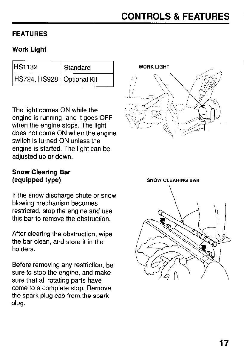
FEATURES
Work Light
The light comes
ON
while the
engine is running, and it goes
OFF
when the engine stops. The light
does not come
ON
when the engine
switch is turned
ON
unless the
engine is started. The light can be
adjusted up or down.
Snow Clearing Bar
(equipped type)
If
the snow discharge chute or snow
blowing mechanism becomes
restricted, stop the engine and use
this bar to remove the obstruction.
After clearing the obstruction, wipe
the bar clean, and store it in the
holders.
Before removing any restriction, be
sure to stop the engine, and make
sure that all rotating parts have
come to a complete stop. Remove
the spark plug cap from. the spark
Plug.
WORK
LIGHT
SNOW CLEARING
BAR
17
ARE YOU READY TO GET STARTED?
Your safety is your responsibility. A little time spent in preparation will
significantly reduce your risk of injury.
Knowledge
Read and understand this manual. Know what the controls do and how to
operate them.
Familiarize yourself with the snowblower and its operation before you begin
using it. Know how to quickly shut off the snowblower in case of an emergency.
IS
YOUR SNOWBLOWER READY
TO
GO?
For your safety, and to maximize the service life of your equipment, it is very
important to take afew moments before you operate the snowblower to check
its condition. Be sure to take care of any problem you find, or have your
servicing dealer correct it, before you operate the snowblower.
improperly maintaining this snowblower, or
failing to correct a problem before operation,
could cause a malfunction in which you could
be seriously injured.
Always perform
a
preoperation inspection
before each operation, and correct any
problem.
Before beginning your preoperation checks, be sure the snowblower is on a
level surface and the engine switch is in the OFF position.
18
BEFORE OPERATION
Check the General Condition
of
the Snowblower:
Look around and underneath the snowblower for signs of oil or gasoline
leaks.
Check the auger house and the discharge chute for accumulation of
packed snow or ice. Clean the auger housing and discharge chute before
starting the snowblower.
Look for signs of damage.
Check each control for proper operation.
Check the auger and blower for loose or broken bolts,
If
broken, replace
them with new ones (page
49).
Check the skid shoes and scraper bar for wear. Replace them if necessary
(page
50).
Check that all nuts, bolts, screws are tightened.
Check the Engine
Check the oil level (page
40).
Check the fuel level (page
38).
Starting with a full tank will help to eliminate
or reduce operating interruptions for refueling.
Check the hydrostatic fluid level in the reservoir (page
43).
Use only
HONDA HYDROSTATIC FLUID.
19
BEFORE OPERATION
CHECK YOUR WORK AREA
For your safety and the safety of others, always inspect the area before
operating the snowblower.
Objects
Anything which can be picked up by the augers and thrown is a potential
hazard to you and others. Look for things like stones, sticks, bones, nails, and
wire, and remove them from the work area.
People
and
Pets
People and animals near the work area can move into your snowblowers path
or into a position where they could be struck by thrown objects. Clear the area
of people, especially children and pets. Their safety is your responsibility.
Work Area
Check the condition of the snow. Adjust your snowblower ground speed (not
engine speed)
and
snowblowing swath accordingly.
Check the skid shoes for proper adjustment. Adjust the skid shoes to obtain
the auger ground clearance for the type of surface the snowblower will be
operated over (page
51).
20
OPERATION
SNOWBLOWING PRECAUTIONS
Before operating the snowblower for the first time, please review both the
SNOWBLOWER SAFETYchapter (page
5)
and the BEFORE OPERATION
chapter (page
18).
Even
if
you have operated other snowblowers, take time to become familiar
with how this snowblower works, and practice in a safe area until you build up
your skills.
Never tamper with, or alter any
of
the controls or safety devices on the
snowblower.
For your safety, avoid starting or operating the engine in an enclosed area
such as a garage. Your snowblower’s exhaust contains poisonous carbon
monoxide gas which can collect rapidly in an enclosed area and cause illness
or death.
Carbon monoxide gas is toxic. Breathing it can
cause unconsciousness and even kill you.
Avoid any enclosed areas or activities that expose
you to carbon monoxide.
STARTING THE ENGINE
1.
Move the shift lever to
“N”
(Neutral) position.
i
I
N
(Neutral)
I
21
OPERATION
2.
Set the transmission release lever
in the ENGAGED position (page
16).
ENGAGED
TRANSMISSION
RELEASE
LEVER
3.
Turn the fuel valve to the ON position.
Be sure that the drain knob is
tightened securely.
\
DRAIN
KNOB
THROlTLE
LEVE
4.
In cold weather and when the engine
is cold, follow the procedures below.
HS624/HS724/HS828/HS928:
Move the throttle lever to the
CHOKE
position.
/
CHOKE
22
OPERATION
HS1132:
Pull the choke knob to the CLOSED position and move the throttle lever to
the
FAST
position.
CHOKE
KNOB
e
CLOSED
THROTTLE
LEVER
5.
Start the engine.
Electric-start
Models
(TAS,
WAS
type):
a. Connect your power cord to the switch box and the male end of the
power cord to a properly grounded
120
volt ac outlet.
I
ACAUTION
I
IUSE ONLY WITH GROUNOEO OUTLET AN0
1120
VOLT A.C. ONLY
100
NOT CRANK OVER
1
MINUTE WllHOLlT
COOLING
15
MINUTES.
100
NOT USE IN RAIN.
3-WIRE CORD.
I
POWER
CORD
To
minimize the possibility
of
potentially dangerous electrical shocks, always
use a 3-conductor power cord with a power rating of no less than
15
amps.
Also,
be sure that the outlet you are using is properly grounded.
Do
not connect and disconnect the power cord with wet hands.
Be sure to hold the plug when disconnecting the power cord from the electrical
outlet or switch box.
Do
not disconnect by pulling on the power cord.
23
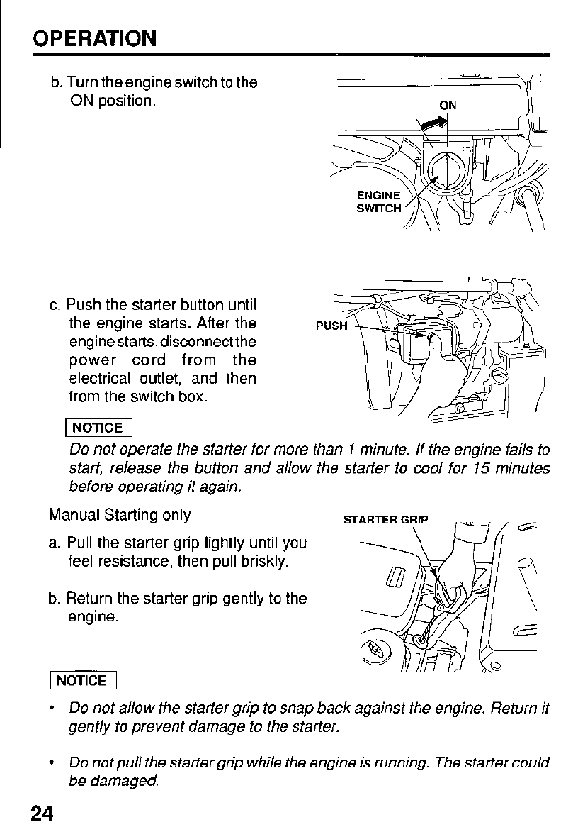
OPERATION
b. Turn the engine switch to the
ON
position.
ON
I
I\
I
c. Push the starter button until
the engine starts. After the
engine starts, disconnect the
power cord from the
electrical outlet, and then
from the switch box.
Do
not operate the starter for more than
1
minute. If the engine fails to
start, release the button and allow the starter to cool for
15
minutes
before operating it again.
Manual Starting only
a. Pull the starter grip lightly until you
feel resistance, then pull briskly.
b. Return the starter grip gently to the
engine.
piEq
Do
not allow the starter grip to snap back against the engine. Return it
gently to prevent damage to the starter.
Do
not pull the starter grip while the engine is running. The starter could
be damaged.
24
OPERATION
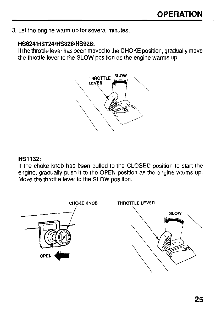
3.
Let the engine warm up for several minutes.
HS624/HS724/HS828/HS928:
If
the throttle lever has been moved to the CHOKE position, gradually move
the throttle lever to the SLOW position as the engine warms up.
HS1132:
If
the choke knob has been pulled to the CLOSED position to start the
engine, gradually push it to the
OPEN
position as the engine warms up.
Move the throttle lever to the SLOW position.
CHOKE KNOB THROTTLE LEVER
OPEN
1,
25
OPERATION
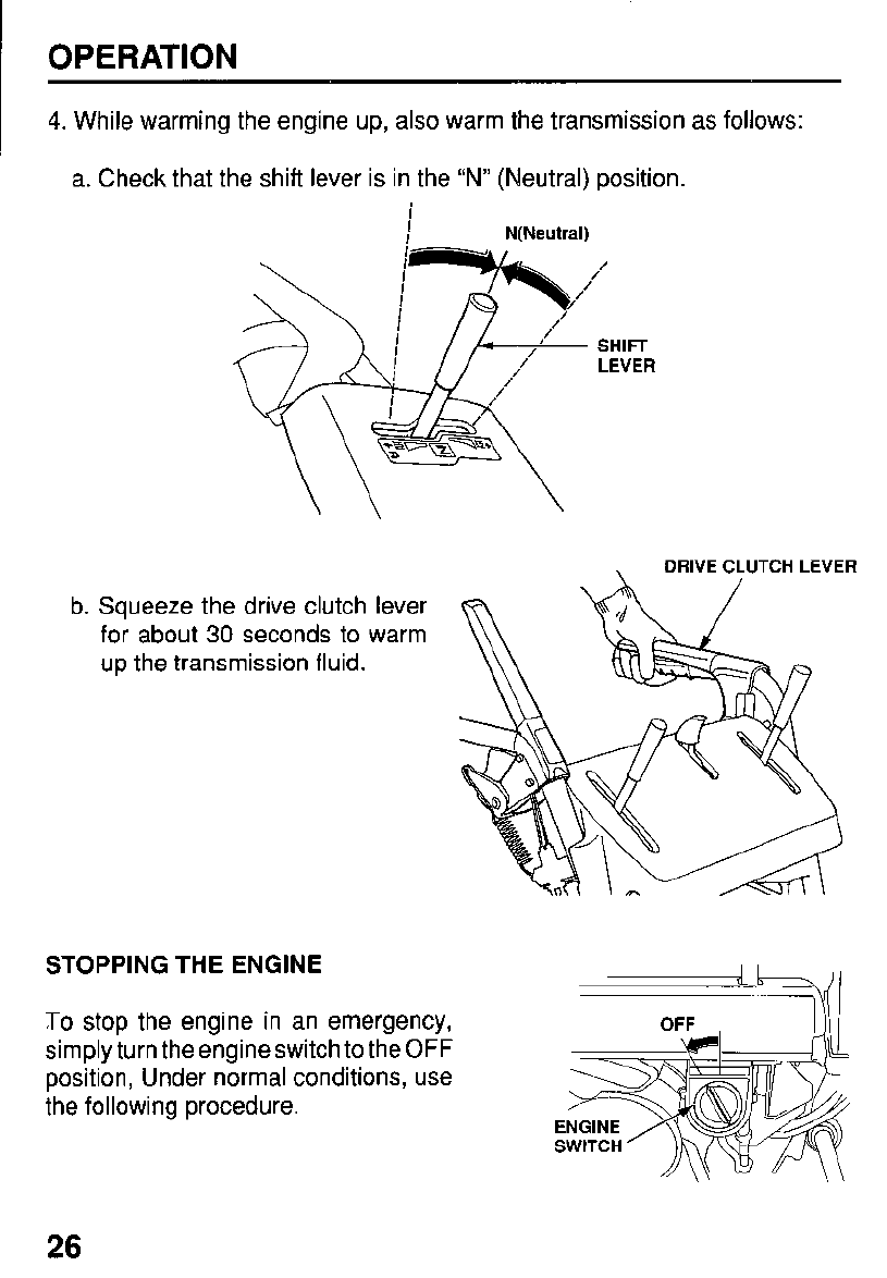
4.
While warming the engine up,
also
warm the transmission as follows:
a. Check that the shift lever is in the
“N”
(Neutral) position.
i
I
I
N(Neutra1)
/
/
SHIFT
LEVER
b.
Squeeze the drive clutch lever
for about
30
seconds to warm
up the transmission fluid.
.
DRIVE
CLUTCH
LEVER
STOPPING THE ENGINE
To
stop the engine in an emergency,
simply turn the engine switch to the
OFF
position, Under normal conditions, use
the following procedure.
26
OPERATION
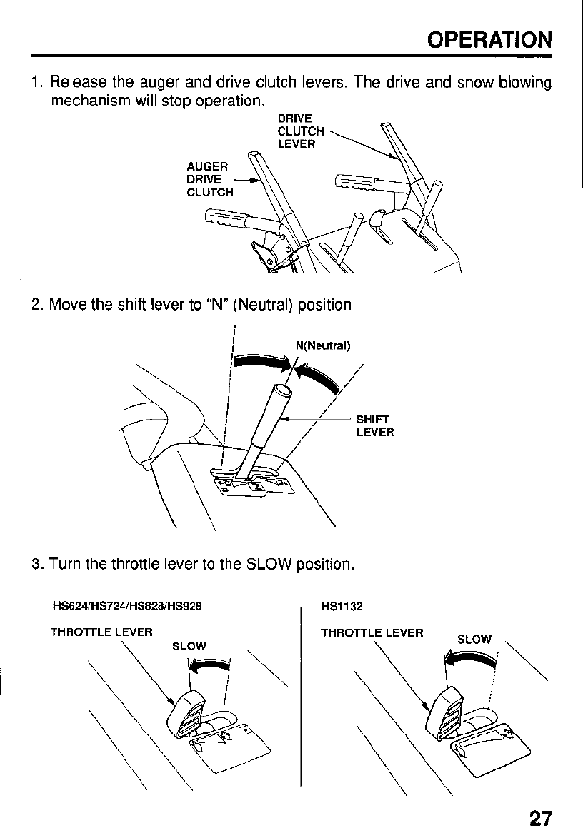
1.
Release the auger and drive clutch levers. The drive and snow
mechanism will stop operation.
DRIVE
CLUTCH
\
LEVER
Release the auger and drive clutch levers. The drive and snow
mechanism will stop operation.
DRIVE
2.
Move the shift lever to “N” (Neutral) position.
i
I
I
N(Neutra1)
blowing
3.
Turn the throttle lever to the
SLOW
position.
HS624lHS724IHS828lHS928
I
HS1132
THROTTLE
LEVER
27
OPERATION
4.
Turn the engine switch to the
OFF
position.
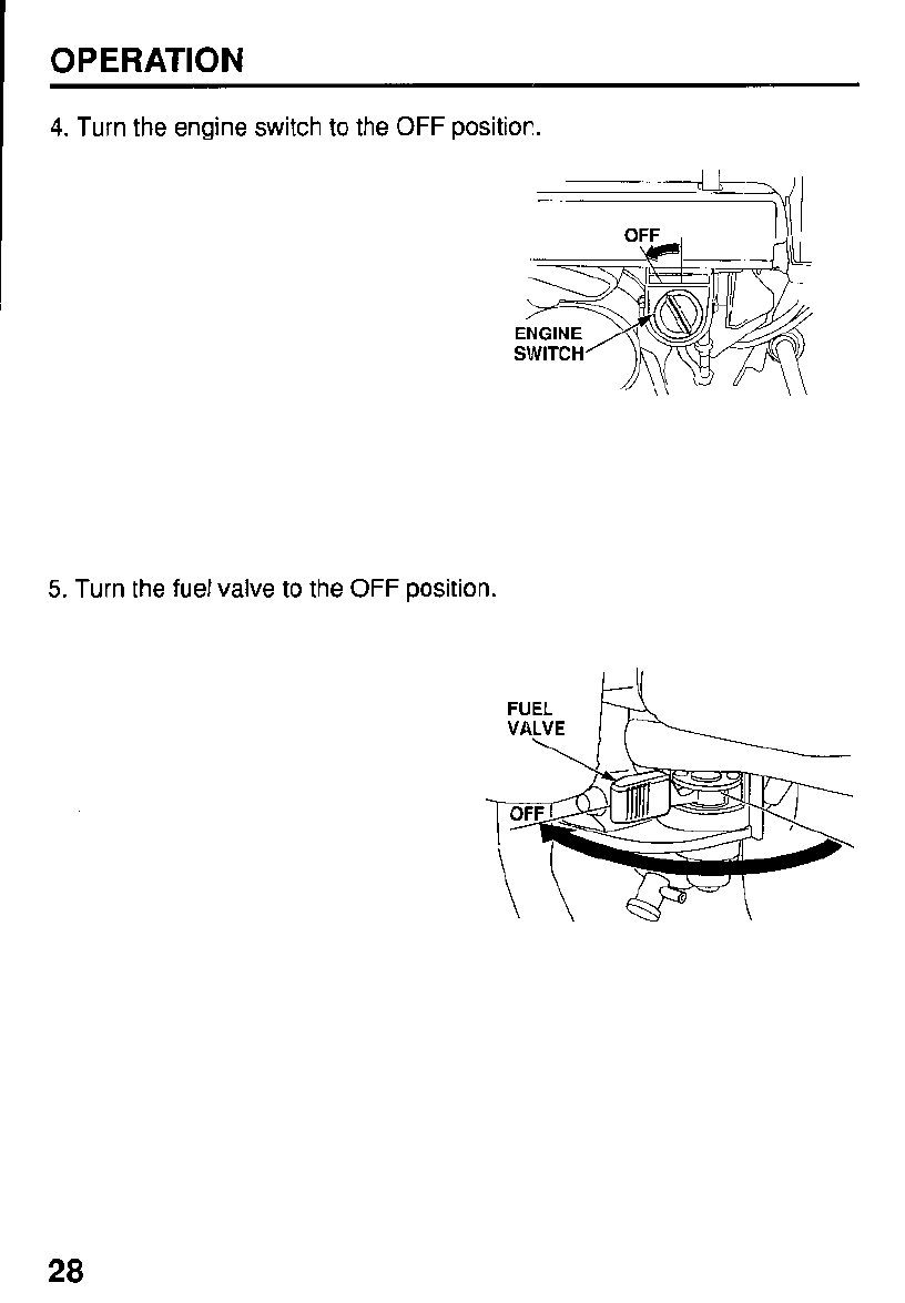
5.
Turn the fuel valve to the
OFF
position.
FUEL
VALVE
\
28
OPERATION
CLEARING SNOW
1.
Move the throttle lever to the FAST position for normal operation.
2.
Release the auger clutch
i
N
(Neutral)
R
(Reverse)
lever, and move the shift
lever to select the desired
drive speed.
Low speed is
recommended for
removing deep or
hardpacked snow.
3.
Set the foot pedal to the
correct position
(page
14,
track type only).
4.
Adjust the throwing direction by using the chute crank and the discharge
deflector lever (page
12
and
14).
5.
Squeeze the auger clutch lever
The machine will clear snow when you squeeze the auger clutch lever.
29
OPERATION
6.
Squeeze the drive clutch lever to self-propel the snowblower.
If
the transmission release lever (page
22)
is in the
ENGAGED
position, and
the shift lever (page
29)
is in the
FORWARD
(F)
position, the hydrostatic
drive will DroDel the snowblower forward when you squeeze the drive clutch
lever.
-~
I,
RIVE
CLUTCH
LEVER
To
move from one place to another, or
to
change direction, use the drive clutch
lever only. Release both the drive clutch lever and auger clutch lever, and then
squeeze the drive clutch lever.
\
DRIVE
CLUTCH
LEVER
30
OPERATION
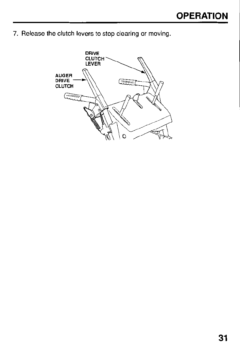
7.
Release the clutch levers to stop clearing or moving.
DRIVE
31
OPERATION
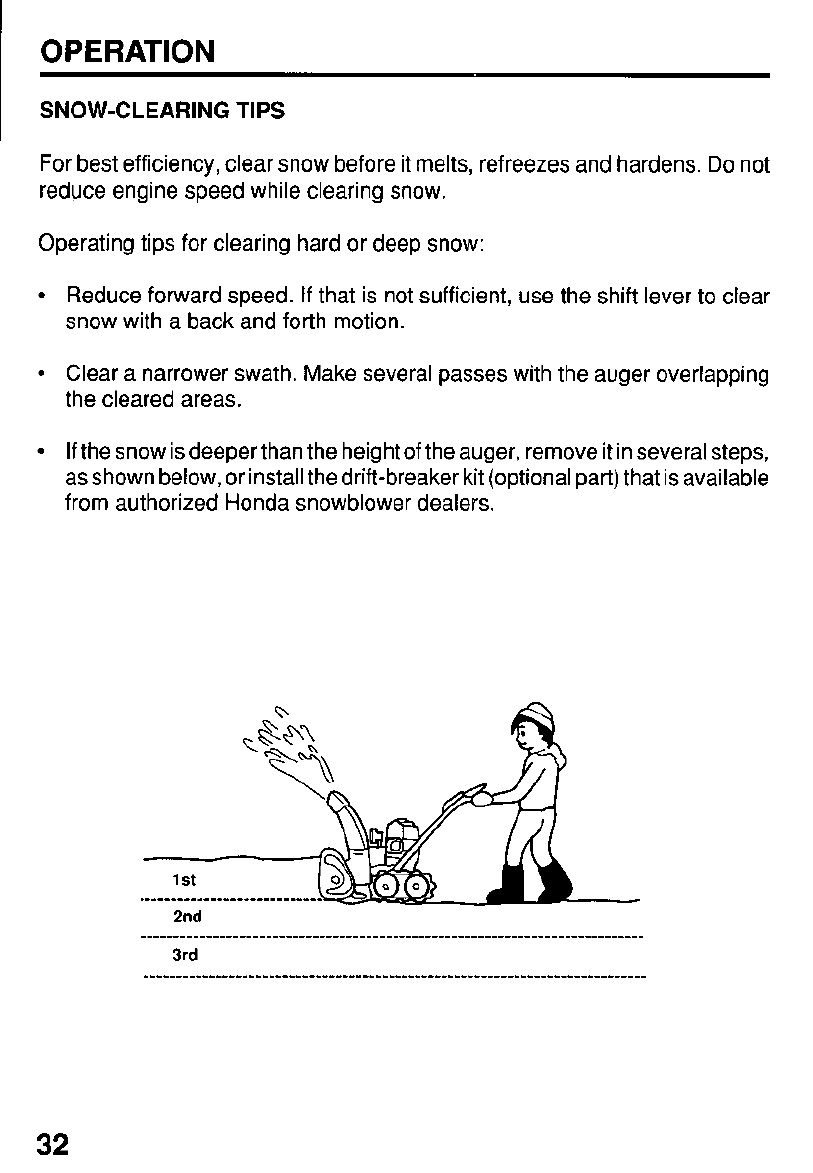
SNOW-CLEARING
TIPS
For best efficiency, clear snow before it melts, refreezes and hardens.
Do
not
reduce engine speed while clearing snow.
Operating tips for clearing hard or deep snow:
Reduce forward speed.
If
that is not sufficient, use the shift lever to clear
snow with a back and forth motion.
Clear a narrower swath. Make several passes with the auger overlapping
the cleared areas.
If
the snow is deeper than the height of the auger, remove it in several steps,
as shown below, or install
the drift-breaker
kit (optional part) that is available
from authorized Honda snowblower dealers.
32
OPERATION
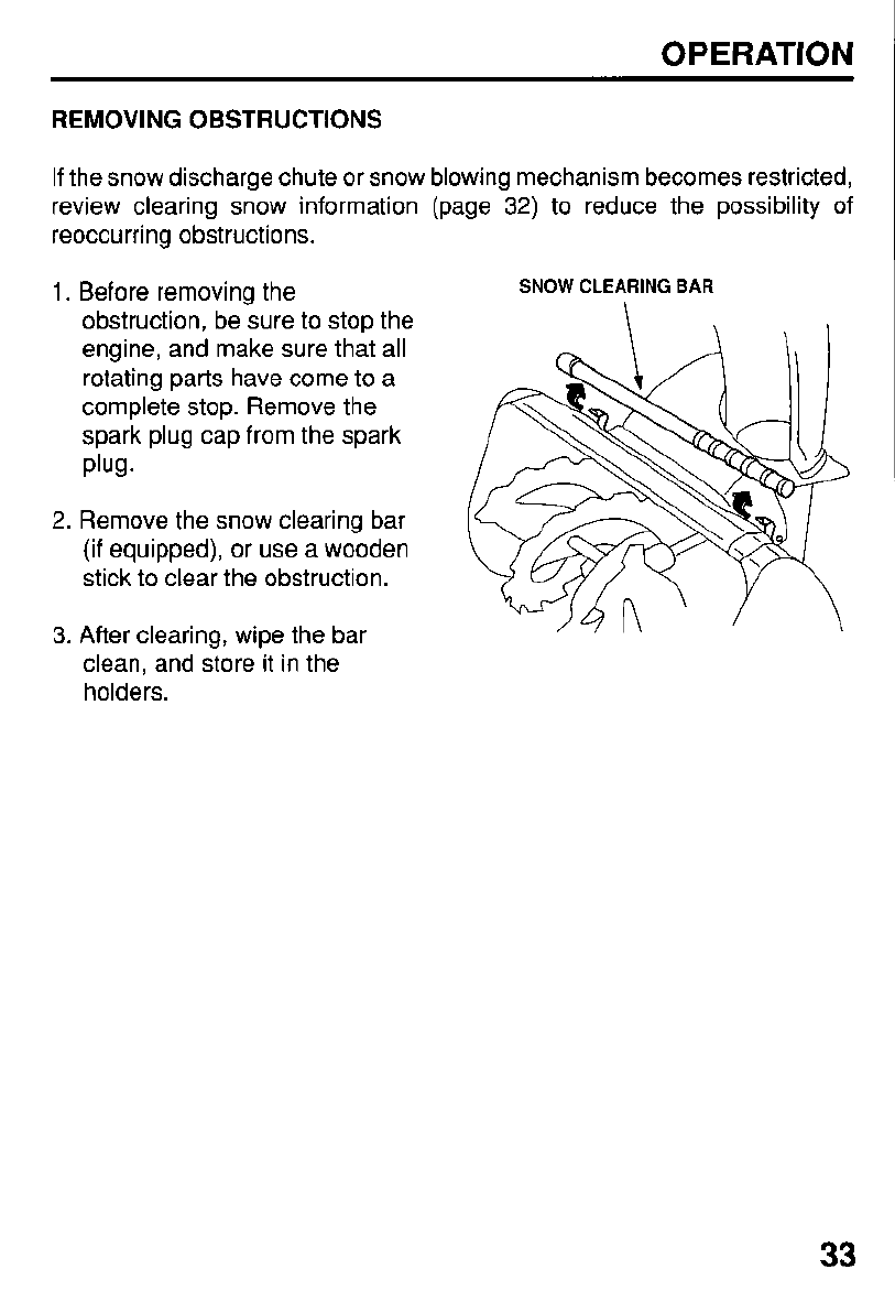
REMOVING OBSTRUCTIONS
If
the snow discharge chute or snow blowing mechanism becomes restricted,
review clearing snow information (page 32) to reduce the possibility of
reoccurring obstructions.
1.
Before removing the
SNOW CLEARING BAR
obstruction, be sure to stop the
engine, and make sure that all
rotating parts have come to
a
complete stop. Remove the
spark plug cap from the spark
Plug.
2. Remove the snow clearing bar
(if equipped), or use a wooden
stick to clear the obstruction.
3. After clearing, wipe the bar
clean, and store it in the
holders.
33
SERVICING YOUR HONDA SNOWBLOWER
THE IMPORTANCE
OF
MAINTENANCE
Good maintenance is essential for safe, economical, and trouble-free operation.
It will also help reduce air pollution.
To help you properly care for your snowblower, the following pages include a
maintenanceschedule, routine inspection procedures, and simple maintenance
procedures using basic hand tools. Other service tasks that are more difficult,
or require special tools, are best handled by professionals and are normally
performed by a Honda technician or other qualified mechanic.
The maintenance schedule applies to normal operating conditions.
If
you
operate your snowblower under unusual conditions, consult your servicing
dealer for recommendations applicable to your individual needs and use.
Remember that your servicing dealer knows your snowblower best and is fully
equipped to maintain and repair it.
Improper maintenance, or failure to correct
a problem before operation, can cause a
malfunction in which you can be seriously
hurt or killed.
Always follow the inspection and
maintenance recommendations and
schedules in this owner’s manual.
To ensure the best quality and reliability, use only new, genuine Honda parts
or their equivalents for repair and replacement.
Maintenance, replacement, or repair of the emission control devices and
systems may be performed by any engine repair establishment or individual,
using parts that are “certified” to EPA standards.
34
SERVICING YOUR HONDA SNOWBLOWER
MAINTENANCE SAFETY
Some of the most important safety precautions follow. However, we cannot
warn you of every conceivable hazard that can arise in performing maintenance.
Only you can decide whether or not you should perform a given task.
Failure to properly follow maintenance
instructions and precautions can cause
you to be seriously hurt or killed.
Always follow the procedures and
precautions in the owner’s manual.
Safety Precautions
Make sure the engine is off before you begin any maintenance or repairs.
This will eliminate several potential hazards:
-
Carbon monoxide poisoning from engine exhaust.
Be sure there is adequate ventilation whenever you operate the engine.
-
Burns from hot parts.
Let the engine and exhaust system cool before touching.
-
Injury from moving parts.
Do
not run the engine unless instructed to do
so.
Read the instructions before you begin, and make sure you have the tools
and skills required.
To
reduce the possibility of fire or explosion, be careful when working
around gasoline. Use only a nonflammable solvent, not gasoline, to clean
parts. Keepcigarettes, sparks, and flames away from all fuelre
-
lated parts.
35
I
SERVICING YOUR HONDA SNOWBLOWER
1
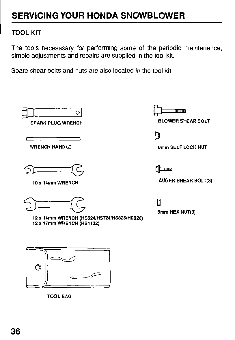
TOOL KIT
The tools necessary for performing some of the periodic maintenance,
simple adjustments and repairs are supplied in the tool kit.
Spare shear bolts and nuts are also located in the tool kit.
rm
0
SPARK
PLUG
WRENCH
WRENCH
HANDLE
-
10
x
14mm
WRENCH
12
x
14mm
WRENCH
(HS624lHS724IHS828lHS928)
12
x
17mm
WRENCH
(HS1132)
3-
1
TOOL BAG
BLOWER
SHEAR
BOLT
6mm
SELF
LOCK NUT
AUGER
SHEAR
BOLT(3)
R
6mm
HEX NUT(3)
36
SERVICING YOUR HONDA SNOWBLOWER
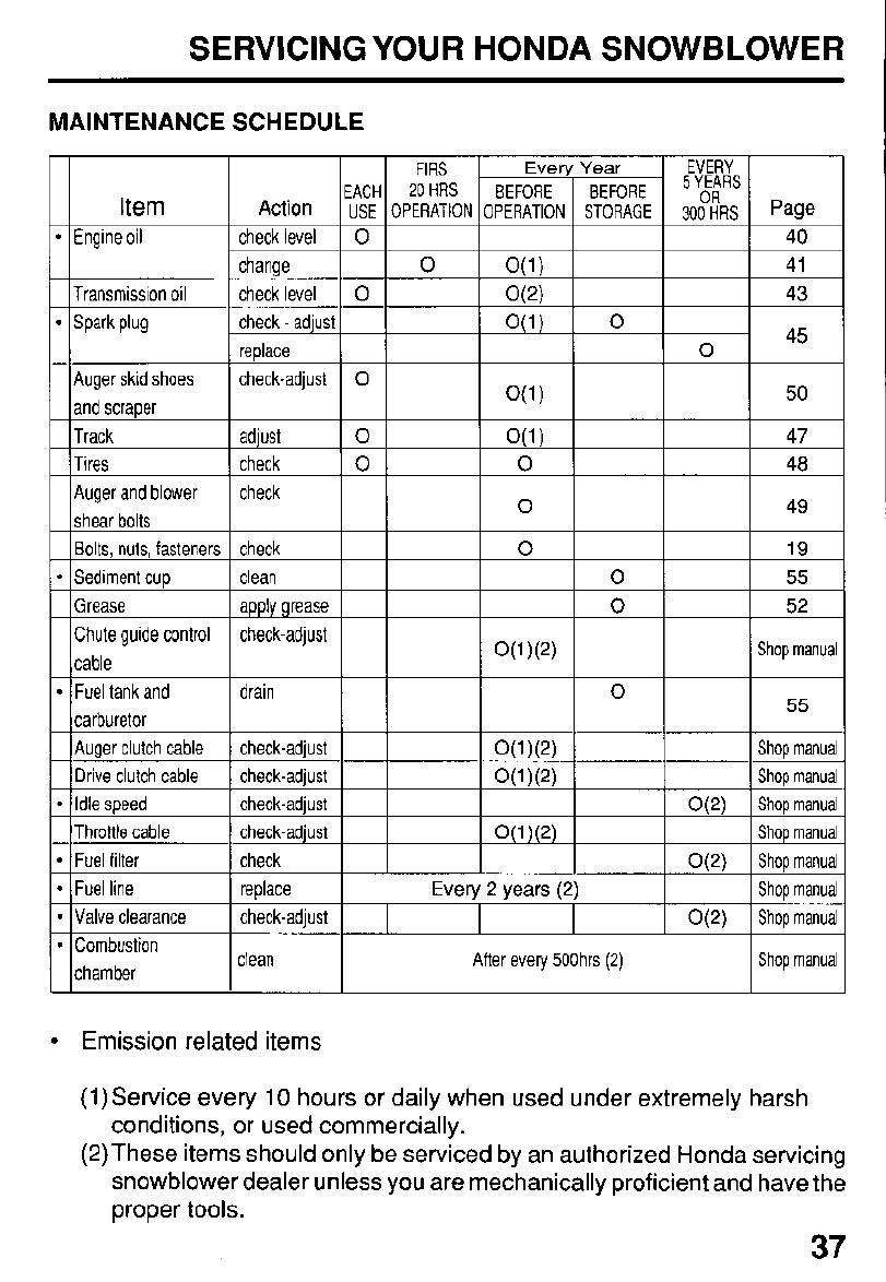
MAINTENANCE SCHEDULE
I
Ever!
BEFORE
)PERATION
5
YEARS
Page
40
41
43
45
50
47
48
49
19
55
52
Shop rnanua
55
Shop manua
Shop rnanua
Shop rnanua
Shop rnanua
Shop rnanua
Shop rnanua
Shop rnanua
Shop manua
00
Auger skid shoes
and scraoer
Track
Auger and blower
Chute guide control
cable
0
0
L
Fuel tank and
carburetor
Auger clutch cable
Drive clutch cable
Idle speed
Fuel filter
Throttle cable
0(1)(2)
replace
Every
2
years
(2)
check-adjust
O(2)
clean After every 500hrs
(2)
Emission related items
(1)Service every 10 hours or daily when used under extremely harsh
conditions, or used commercially.
(2)These items should only be serviced by an authorized Honda servicing
snowblower dealer unless you are mechanically proficient and have the
proper tools.
37
SERVICING YOUR HONDA SNOWBLOWER
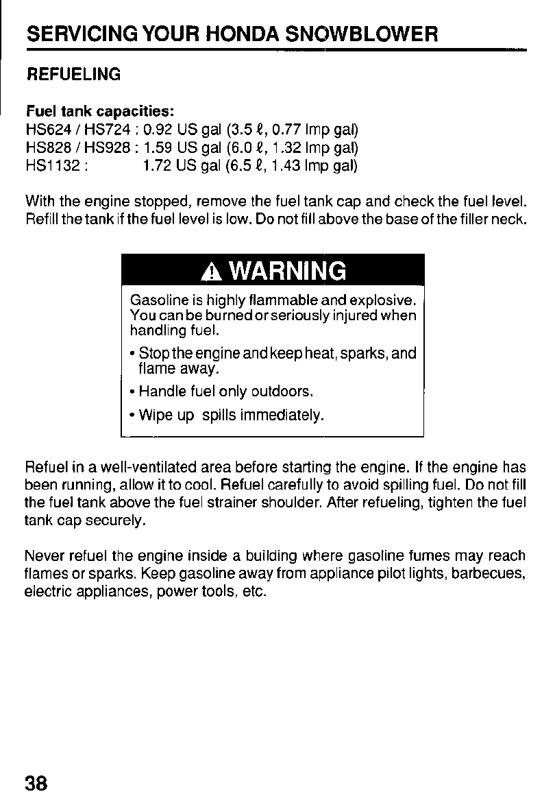
REFUELING
Fuel
tank capacities:
HS624
/
HS724
:
0.92
US
gal (3.5
t,
0.77 Imp gal)
HS828
/
HS928
:
1.59
US
gal (6.0
t,
1.32 Imp gal)
HS1132
:
1.72
US
gal (6.5
e,
1.43 Imp gal)
With the engine stopped, remove the fuel tank cap and check the fuel level.
Refill the tank if the fuel level is low.
Do
not fill above the base of the filler neck.
Gasoline is highly flammable and explosive.
You can be burned or seriously injured when
handling fuel.
Stop the engine and keep heat, sparks, and
flame away.
Handle fuel only outdoors.
Wipe up spills immediately.
Refuel in a well-ventilated area before starting the engine.
If
the engine has
been running, allow it to cool. Refuel carefully to avoid spilling fuel.
Do
not fill
the fuel tank above the fuel strainer shoulder. After refueling, tighten the fuel
tank cap securely.
Never refuel the engine inside a building where gasoline fumes may reach
flames or sparks. Keep gasoline away from appliance pilot lights, barbecues,
electric appliances, power tools, etc.
38
SERVICING YOUR HONDA SNOWBLOWER
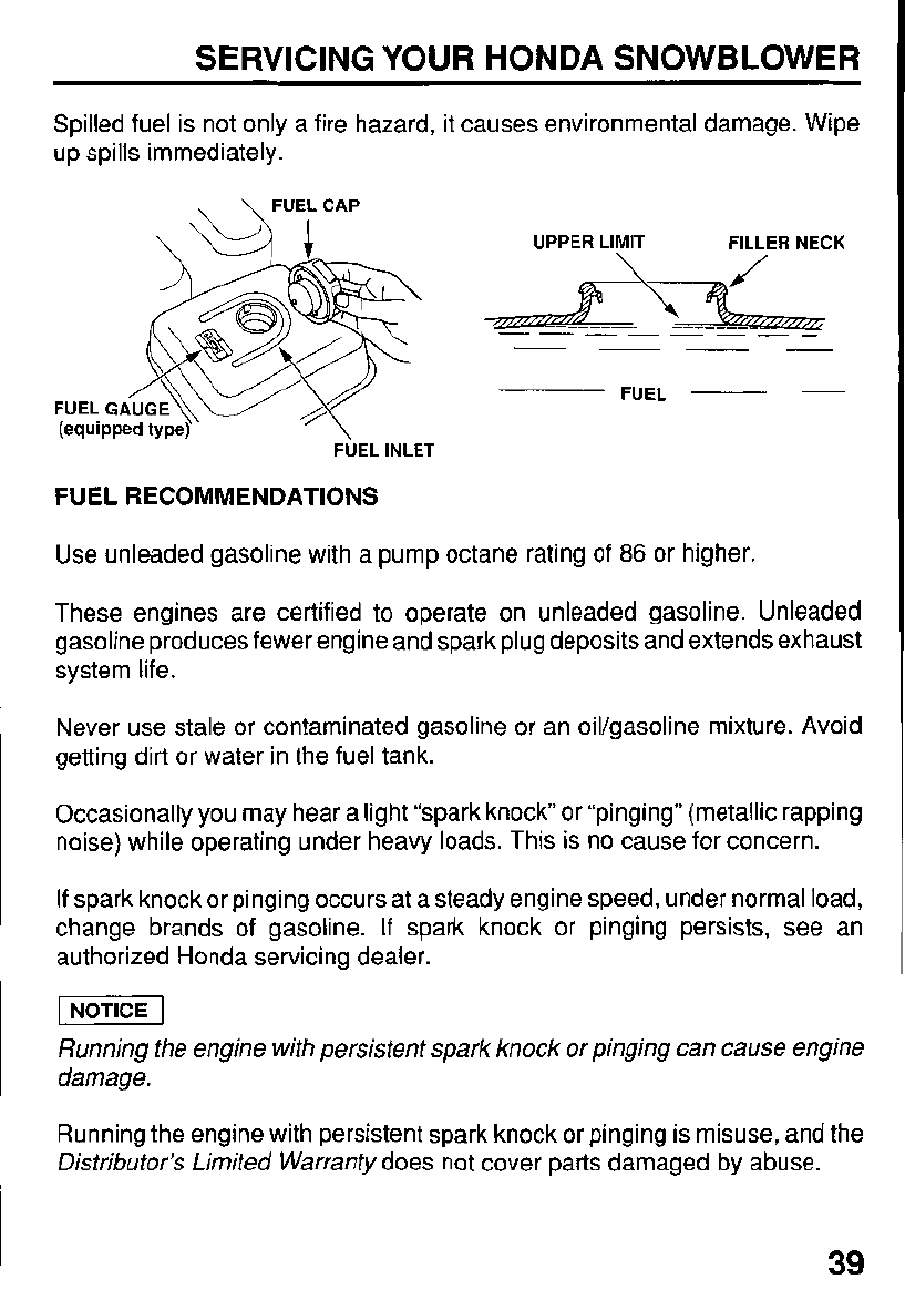
Spilled fuel is not only a fire hazard, it causes environmental damage. Wipe
up spills immediately.
,
\
FUELCAP
\
ur
FUEL
(equi
UPPER LIMIT FILLER NECK
FUEL
~
-
FUEL INLET
FUEL RECOMMENDATIONS
Use unleaded gasoline with a pump octane rating of
86
or higher.
These engines are certified to operate on unleaded gasoline. Unleaded
gasoline produces fewer engine and spark plug deposits and extends exhaust
system life.
Never use stale or contaminated gasoline or an oil/gasoline mixture. Avoid
getting dirt or water in the fuel tank.
Occasionally you may hear a light “spark knock or “pinging” (metallic rapping
noise) while operating under heavy loads. This is no cause for concern.
If
spark knock
or
pinging occurs at a steady engine speed, under normal load,
change brands
of
gasoline.
If
spark knock or pinging persists, see an
authorized Honda servicing dealer.
Running the engine with persistent spark knock or pinging can cause engine
damage.
Running the engine with persistent spark knock or pinging is misuse, and the
Distributor’s Limited Warranty
does not cover parts damaged by abuse.
39
SERVICING YOUR HONDA SNOWBLOWER
ENGINE
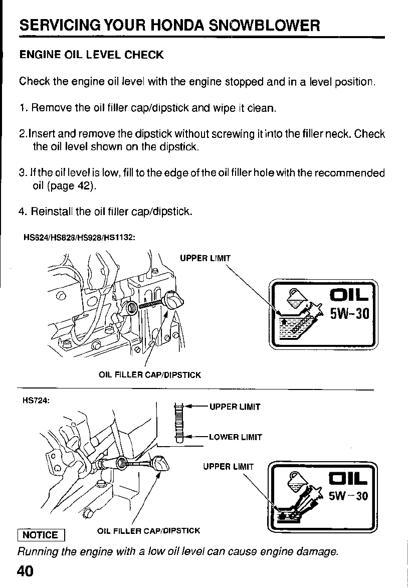
OIL LEVEL CHECK
Check the engine oil level with the engine stopped and in a level position.
1.
Remove the oil filler cap/dipstick and wipe it clean.
2.lnset-t and remove the dipstick without screwing it into the filler neck. Check
the oil level shown on the dipstick.
3.
If
the oil level is low,
fill
to the edge
of
the oil filler hole with the recommended
oil (page
42).
4.
Reinstall the oil filler cap/dipstick.
HS624lHS828lHS9281HS1132:
UPPER
LlMl
OIL
FILLER
CAPIDIPSTICK
Running the engine with a low oil level can cause engine damage.
40
SERVICING YOUR HONDA SNOWBLOWER
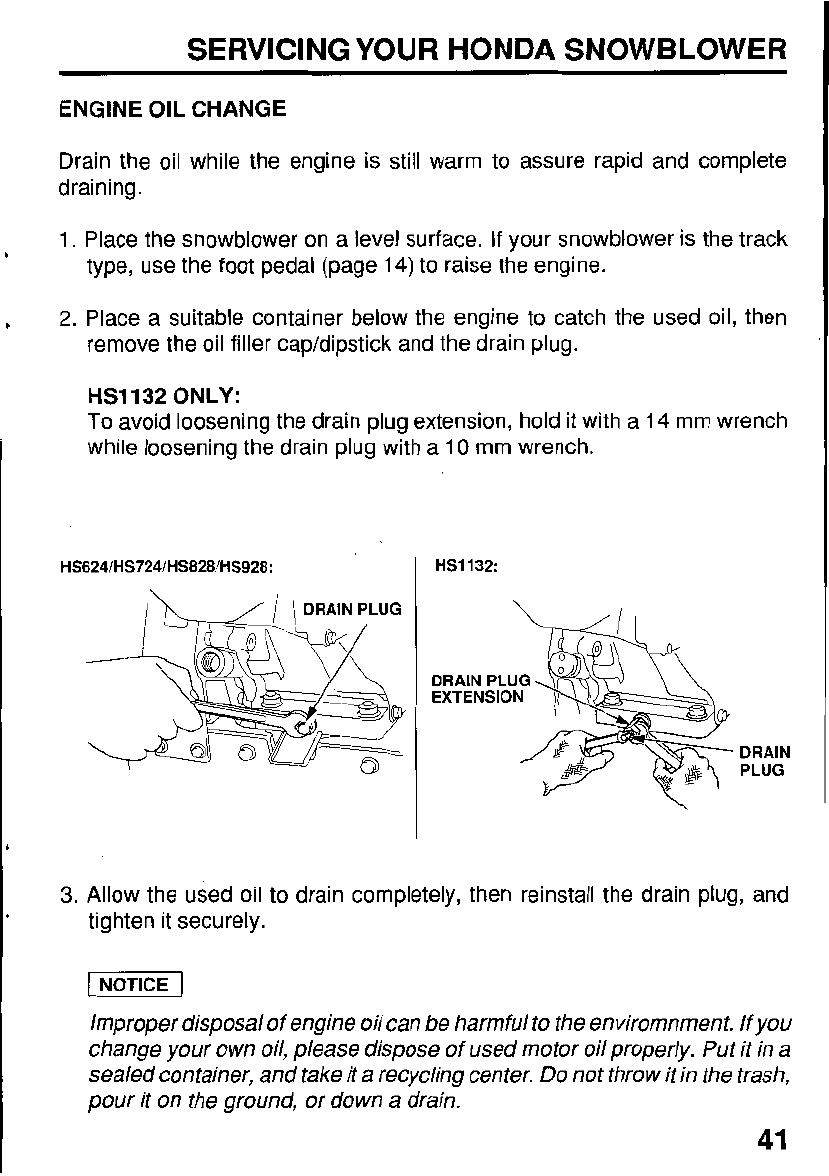
ENGINE
OIL
CHANGE
Drain the oil while the engine is still warm to assure rapid and complete
draining.
1. Place the snowblower on a level surface.
If
your snowblower is the track
type, use the foot pedal (page 14)
to
raise the engine.
2.
Place a suitable container below the engine to catch the used oil, then
remove the oil filler cap/dipstick and the drain plug.
HS1132 ONLY:
To
avoid loosening the drain plug extension, hold it with a 14 mm wrench
while loosening the drain plug with a 10 mm wrench.
HS1132:
EXTENSION
DRAIN
PLUG
3.
Allow the used oil to drain completely, then reinstall the drain plug, and
tighten it securely.
Improper disposal of engine oil can be harmful to the enviromnment. If you
change your own oil, please dispose of used motor oil properly. Put it in a
sealed container, and take it
a
recycling center.
Do
not throw it in the trash,
pour it
on
the ground, or down a drain.
41
SERVICING YOUR HONDA SNOWBLOWER
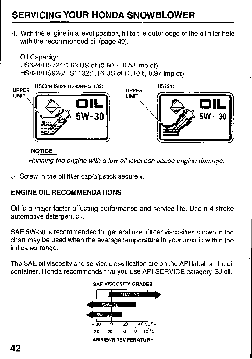
4. With the engine in a level position, fill to the outer edge of the oil filler hole
with the recommended oil (page
40).
Oil Capacity:
HS624/HS724:0.63
US
qt (0.60
i?,
0.53 Imp qt)
HS828/HS928/HS1132:1.16
US
qt (1.10
4,
0.97
Imp qt)
HS624/HS828/HS928/HS1132:
UPPER UPPER
LIMIT
HS724:
9
5W-30
-1
Running the engine with a low oil level can cause engine damage.
5.
Screw in the oil filler cap/dipstick securely.
ENGINE
OIL
RECOMMENDATIONS
oil
is a f'najor factor affecting performance and service life. Use a 4-stroke
automotive detergent oil.
SAE 5W-30 is recommended for general use. Other viscosities shown in the
chart may be used when the average temperature in your area is within the
indicated range.
The SAE oil viscosity and service classification are on the API label on the oil
container. Honda recommends that you use API SERVICE category
SJ
oil.
I
42
SAE VISCOSITY GRADES
-20
0
20
40
50°F
-30
-20
-10
0
10°C
AMBIENR TEMPERATURE
SERVICING YOUR HONDA SNOWBLOWER
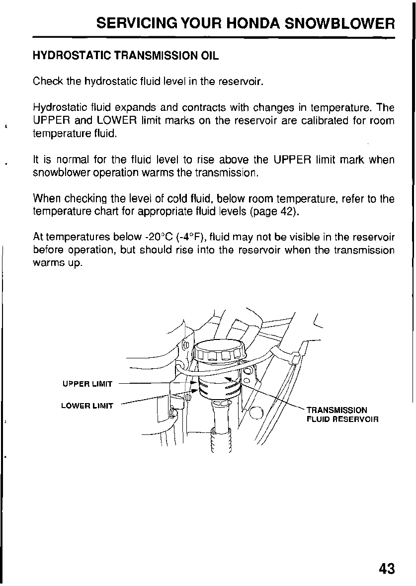
HYDROSTATIC TRANSMISSION
OIL
Check the hydrostatic fluid level in the reservoir.
Hydrostatic fluid expands and contracts with changes in temperature. The
UPPER and LOWER limit marks
on
the reservoir are calibrated for room
temperature fluid.
It
is normal for the fluid level to rise above the UPPER limit mark when
snowblower operation warms the transmission.
When checking the level of cold fluid, below room temperature, refer to the
temperature chart for appropriate fluid levels (page
42).
At temperatures below
-20°C
(-4"F),
fluid may not be visible in the reservoir
before operation, but should rise into the reservoir when the transmission
warms up.
UPPER
LIMIT
LOWER
LIMIT TRANSMISSION
FLUID
RESERVOIR
43
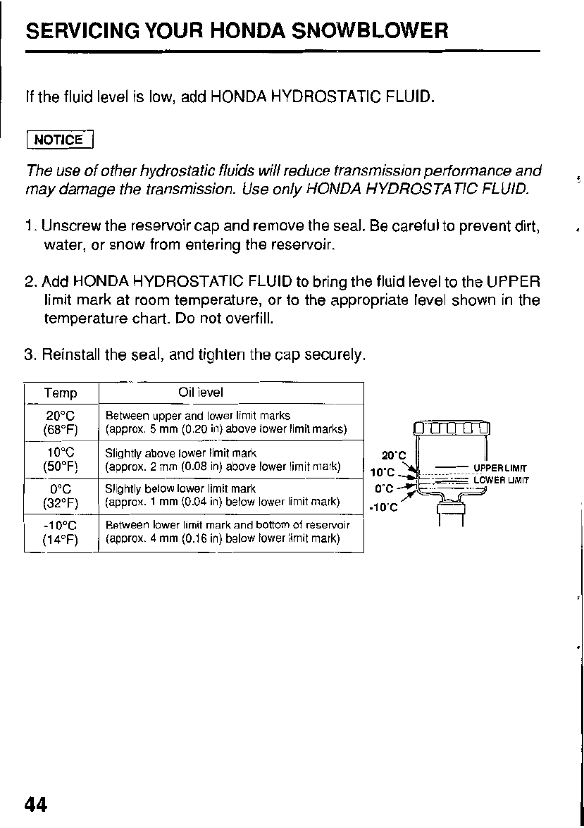
~ SERVICING YOUR HONDA SNOWBLOWER
If
the fluid level
is
low, add HONDA HYDROSTATIC FLUID.
pEEq
The use of other hydrostatic fluids will reduce transmission performance and
may damage the transmission. Use only HONDA HYDROSTATIC FLUID.
1.
Unscrew the reservoir cap and remove the seal. Be careful to prevent dirt,
water, or snow from entering the reservoir.
2.
Add HONDA HYDROSTATIC FLUID to bring the fluid level to the UPPER
limit mark at room temperature, or to the appropriate level shown in the
temperature chart. Do not overfill.
3.
Reinstall the seal, and tighten the cap securely.
(68°F)
(50°F)
(32°F)
-1
0°C
(1
4°F)
Oil
level
Between upper and lower limit marks
(approx.
5
mm
(0.20
in) above lower limit marks)
Slightly above lower limit mark
(approx.
2
mm
(0.08
in) above lower limit mark)
Slightly below lower limit mark
(approx.
1
mm
(0.04
in) below lower limit mark)
Between lower limit mark and bottom
of
reservoir
(approx.
4
mm
(0.16
in) below lower limit mark)
44
SERVICING
YOUR
HONDA SNOWBLOWER
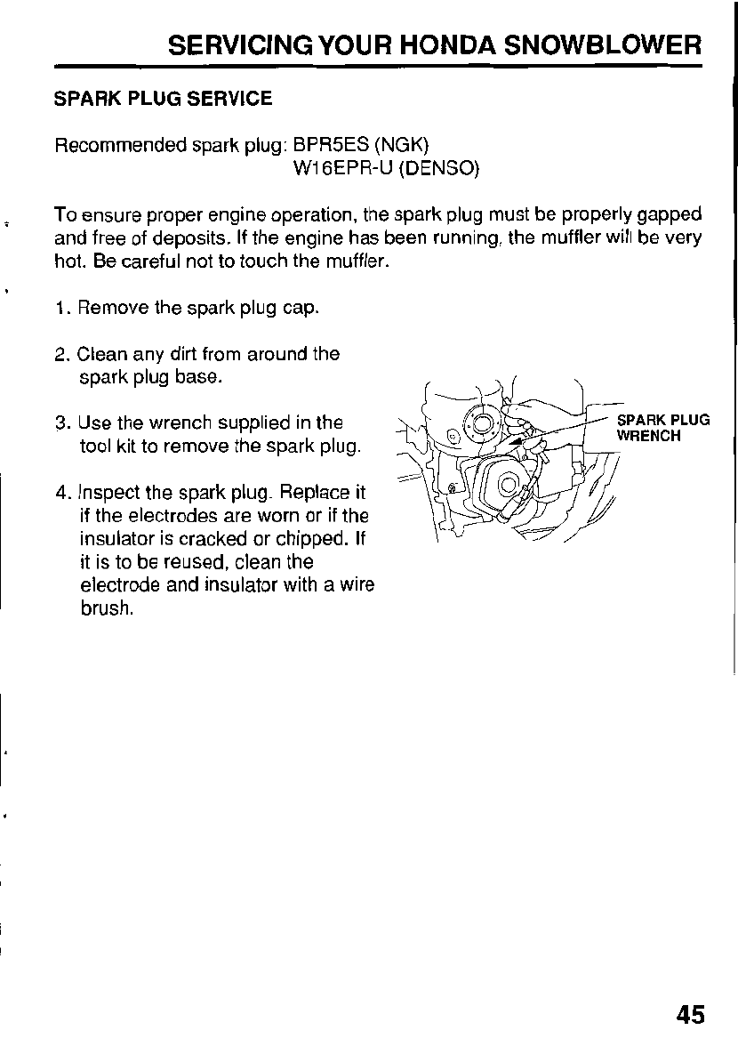
SPARK
PLUG
SERVICE
Recommended spark plug: BPR5ES
(NGK)
W1
GEPR-U
(DENSO)
To
ensure proper engine operation, the spark plug must be properly gapped
and free of deposits.
If
the engine has been running, the muffler will be very
hot. Be careful not to touch the muffler.
1.
Remove the spark plug cap.
2.
Clean any dirt from around the
spark plug base.
3.
Use the wrench supplied in the
tool kit to remove the spark plug.
4.
Inspect the spark plug. Replace it
if
the electrodes are worn or if the
insulator is cracked or chipped.
If
it is to be reused, clean the
electrode and insulator with a wire
brush.
SPARK
PLUG
RENCH
45
SERVICING
YOUR
HONDA SNOWBLOWER
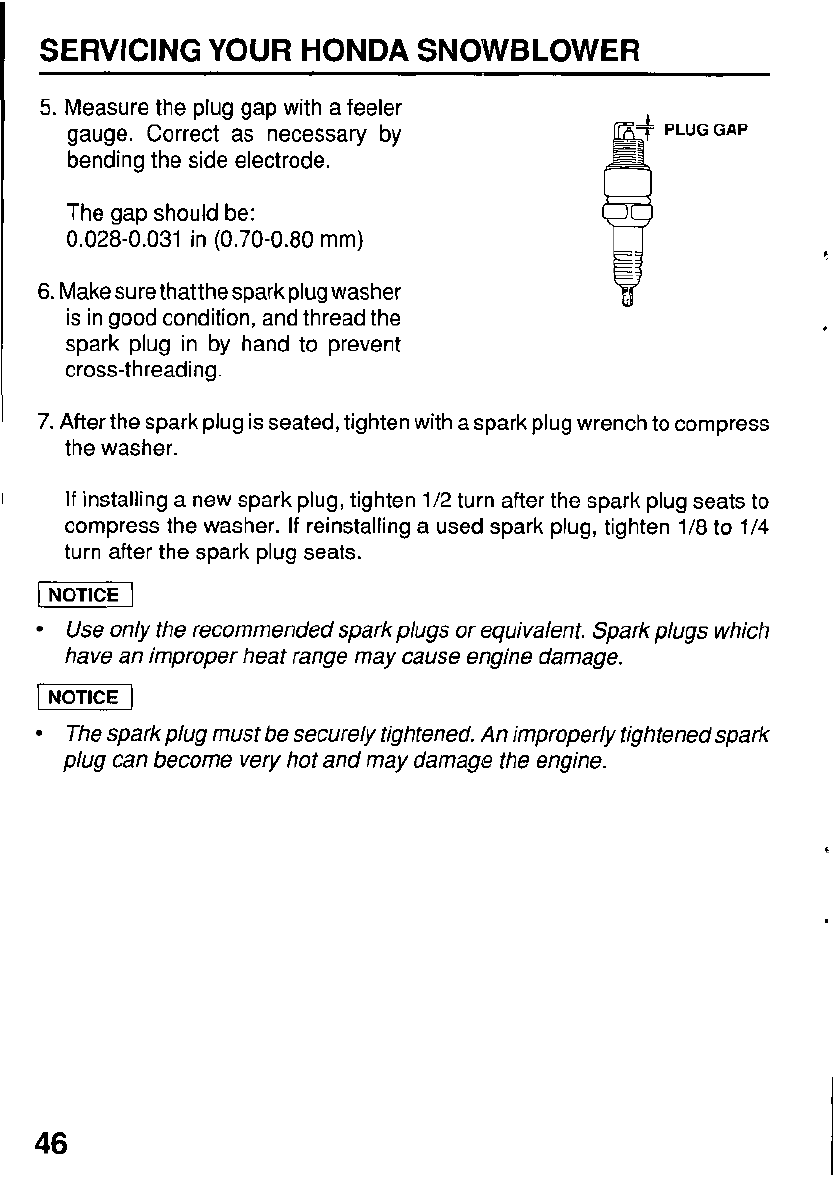
5.
Measure the plug gap with a feeler
gauge. Correct as necessary by
bending the side electrode.
The gap should be:
0.028-0.031 in (0.70-0.80 mm)
6.
Make sure that the sparkplug washer
is in good condition, and thread the
spark plug in by hand to prevent
cross-threading.
R
PLUGGAP
7.
After the spark plug
is
seated, tighten with a spark plug wrench to compress
the washer.
If
installing a new spark plug, tighten 1/2 turn after the spark plug seats to
compress the washer.
If
reinstalling a used spark plug, tighten 1/8 to 1/4
turn after the spark plug seats.
Use only the recommended spark plugs
or
equivalent. Spark plugs which
have an improper heat range may cause engine damage.
The spark plug must be securely tightened.
An
improperly tightened spark
plug can become very hot and may damage the engine.
46
SERVICING YOUR HONDA SNOWBLOWER
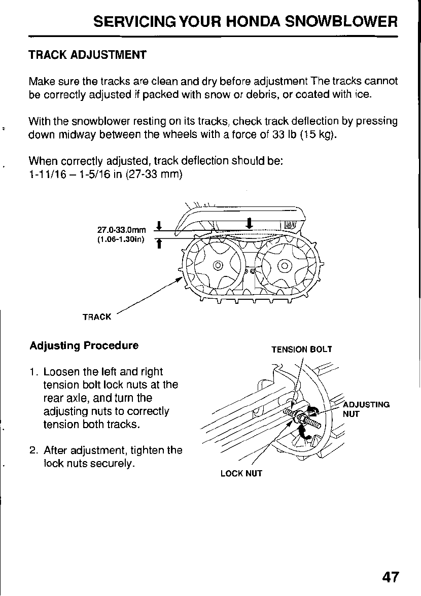
TRACK ADJUSTMENT
Make sure the tracks are clean and dry before adjustment The tracks cannot
be correctly adjusted if packed with snow or debris, or coated with ice.
With the snowblower resting on its tracks, check track deflection by pressing
down midway between the wheels with a force of
33
Ib
(15
kg).
When correctly adjusted, track deflection should be:
1-1
1/16
-
1-5/16
in
(27-33
mm)
27.0-33.0mm
(1.06-1.30in)
/
TRACK
’
Adjusting Procedure
1.
Loosen the left and right
tension bolt lock nuts at the
rear axle, and turn the
adjusting nuts to correctly
tension both tracks.
2.
After adjustment, tighten the
lock nuts securely.
TENSION BOLT
DJUSTING
UT
LOCK
NUT
47
~ SERVICING YOUR HONDA SNOWBLOWER
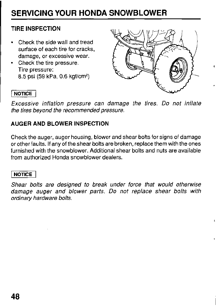
TIRE INSPECTION
Check the side wall and tread
surface of each tire for cracks,
damage, or excessive wear.
Tire pressure:
8.5
psi
(59
kPa,
0.6
kgf/cm*)
Check the tire pressure.
I
NOTICE
1
Excessive inflation pressure can damage the tires.
Do
not inflate
the tires beyond the recommended pressure.
AUGER AND BLOWER INSPECTION
Check the auger, auger housing, blower and shear bolts for signs of damage
or other faults.
If
any of the shear bolts are broken, replace them with the ones
furnished with the snowblower. Additional shear bolts and nuts are available
from authorized Honda snowblower dealers.
Shear bolts are designed to break under force that would otherwise
damage auger and blower parts.
Do
not replace shear bolts with
ordinary hardware bolts.
48
SERVICING YOUR HONDA SNOWBLOWER
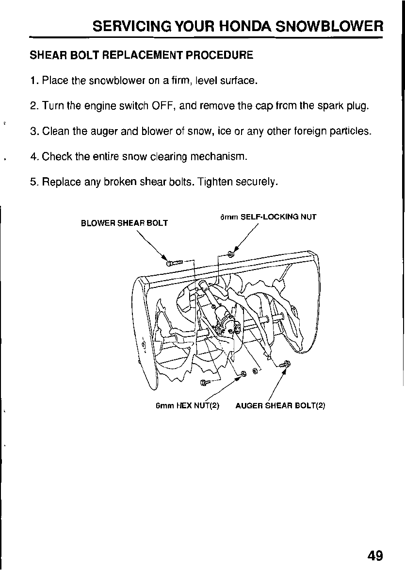
SHEAR BOLT REPLACEMENT PROCEDURE
1.
Place the snowblower on a firm, level surface.
2.
Turn the engine switch
OFF,
and remove the cap from the spark plug.
3.
Clean the auger and blower of snow, ice or any other foreign particles.
4.
Check the entire snow clearing mechanism.
5.
Replace any broken shear bolts. Tighten securely.
BLOWER SHEAR BOLT 6mm SELF-LOCKING NUT
/
6mm HEX NU?(2) AUGER SHEAR BOLT(2)
49
SERVICING YOUR HONDA SNOWBLOWER
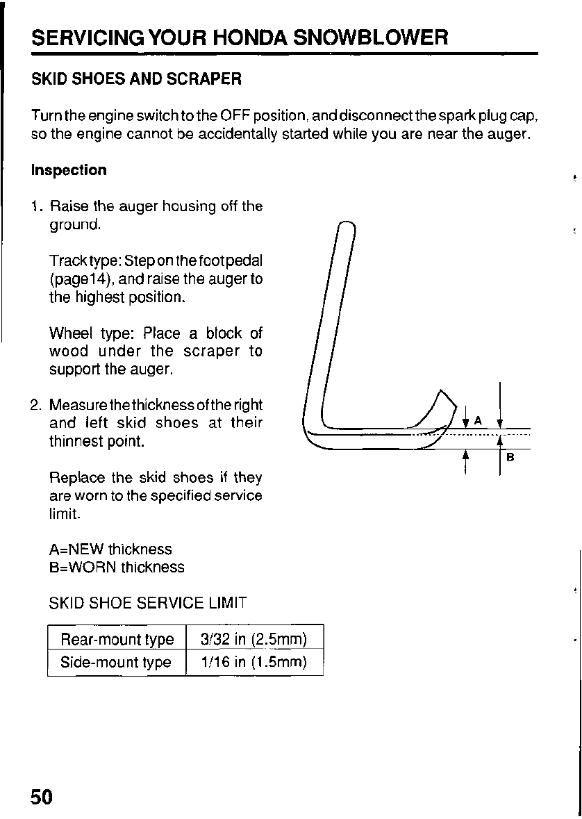
SKID SHOES AND SCRAPER
Turn the engine switch to the
OFF
position, and disconnect the spark plug cap,
so
the engine cannot be accidentally started while you are near the auger.
Inspection
1.
Raise the auger housing off the
ground.
Track type: Step on the foot pedal
(page1
4),
and raise the auger to
the highest position.
Wheel type: Place a block
of
wood under the scraper to
support the auger.
2. Measure the thicknessof the right
and left skid shoes at their
thinnest point.
Replace the skid shoes
if
they
are worn to the specified service
limit.
A=NEW thickness
B=WORN
thickness
SKID
SHOE
SERVICE LIMIT
Rear-mount type
1/16 in (1.5mm)
Side-mount type
3/32 in (2.5mm)
50
SERVICING
YOUR
HONDA SNOWBLOWER
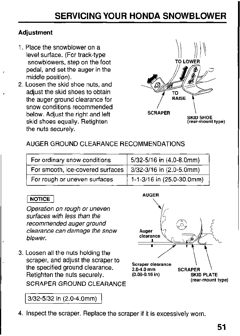
Adjustment
1. Place the snowblower on a
level surface. (For track-type
snowblowers, step on the foot
TO
LOWER
pedal, and set the auger in the
middle position).
2. Loosen the skid shoe nuts, and
adjust the skid shoes
to
obtain
the auger ground clearance for
snow conditions recommended
below. Adjust the right and left
skid shoes equally. Retighten
the nuts securely.
SKID
SHOE
(rear-mount type)
AUGER GROUND CLEARANCE RECOMMENDATIONS
I
For ordinary snow conditions
I
5/32-5/16 in
(4.0-8.0mm)
I
I
For smooth, ice-covered surfaces
1
3/32-3/16 in (2.0-5.0mm)
I
1
For rough or uneven surfaces
I
1-1-3/16
in
(25.0-30.0mm)
1
pECE-1
Operation on rough
or
uneven
surfaces with less than the
recommended auger ground
clearance can damage the snow
blower.
3. Loosen all the nuts holding the
scraper, and adjust the scraper to
the specified ground clearance.
Retighten the nuts securely.
SCRAPER
GROUND CLEARANCE
AUGER
\/;
li..
/
\\
Scraper clearance
2.0-4.0
mm
SCRAPER
'\
(0.08-0.16
in) SKID
PLATE
(rear-mount type)
I
3/32-5/32 in (2.0-4.0mm)
I
4.
Inspect the scraper. Replace the scraper
if
it is excessively worn.
STORAGE
STORAGE PREPARATION
Proper storage preparation is essential for keeping your snowblower troublefree
and looking good. The following steps will help to keep rust and corrosion from
impairing your snowblower's function and appearance, and will make the
engine easier
to
start when you use the snowblower again.
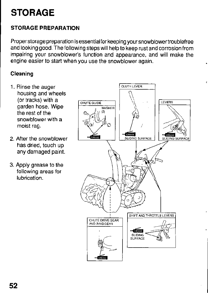
Cleaning
1.
Rinse the auger
housing and wheels
(or tracks) with a
garden hose. Wipe
the rest of the
snowblower with a
moist rag.
2.
After the snowblower
has dried, touch up
any damaged paint.
3.
Apply grease to the
following areas for
lubrication.
I
CLUTH LEVER
I/
4
SLIDING SURFACE
LEVERS
1
AND RING GEAR
I
SHIFT AND THROTTLE LEVERS
SURFACE
SLIDING
1
52
STORAGE
Fuel
Gasoline will oxidize and deteriorate in storage. Old gasoline will cause hard
starting, and it leaves gum deposits that clog the fuel system.
If
the gasoline
in your snowblower deteriorates during storage, you may need to have the
carburetor and other fuel system components serviced or replaced.
The length of time that gasoline can be left in your fuel tank and carburetor
.
without causing functional problems will vary with such factors as gasoline
blend, your storage temperatures, and whether the fuel tank is partially or
completely filled. The air in a partially filled fuel tank promotes fuel deteriora-
tion. Very warm storage
/
temperatures accelerate fuel deterioration. Fuel
deterioration problems may occur within a few months, or even less
if
the
gasoline was not fresh when you filled the fuel tank.
The
Distributor’s Limited Warranty
does not cover fuel system damage or
engine performance problems resulting from neglected storage preparation.
You
can extend fuel storage life by adding a fuel stabilizer that is formulated
for that purpose, or you can avoid fuel deterioration problems by draining the
fuel tank and carburetor.
53
I
STORAGE
1
Adding a Fuel Stabilizer
lo
Extend Fuel Storage Life
When adding a fuel stabilizer,
fill
the fuel tank with fresh gasoline.
If
only
partially filled, air in the tank will promote fuel deterioration during storage.
If
you keepacontainer of gasoline for refueling, be sure that it containsonly fresh
gasoline.
Add fuel stabilizer following the manufacturer's instructions.
After adding a fuel stabilizer, run the engine outdoors for
10
minutes to be sure
that treated gasoline has replaced the untreated gasoline in the carburetor.
Stop the engine, and move the fuel valve lever to the
OFF
position.
54
STORAGE
~
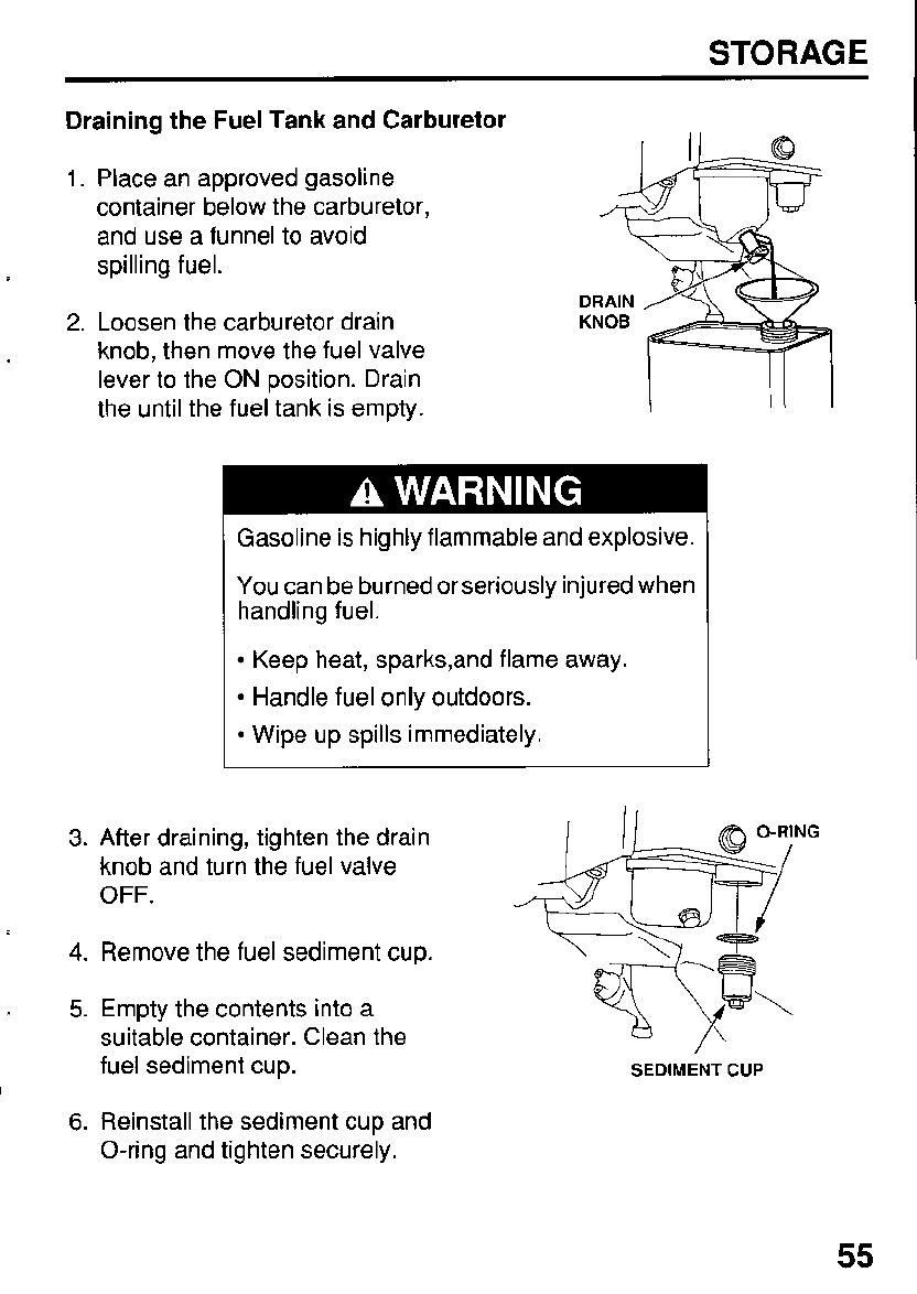
Draining the
Fuel
Tank and Carburetor
1.
Place an approved gasoline
container below the carburetor,
and use a funnel to avoid
spilling fuel.
2.
Loosen the carburetor drain
knob, then move the fuel valve
lever to the
ON
position. Drain
the until the fuel tank is empty.
Gasoline is highly flammable and explosive.
You can be burned or seriously injured when
handling fuel.
Keep heat, sparks,and flame away.
Handle fuel only outdoors.
Wipe up spills immediately.
3.
After draining, tighten the drain
knob and turn the fuel valve
OFF.
4.
Remove the fuel sediment cup.
.
5.
Empty the contents into a
suitable container. Clean the
fuel sediment cup.
SEDIMENT
CUP
6.
Reinstall the sediment cup and
O-ring and tighten securely.
55
STORAGE
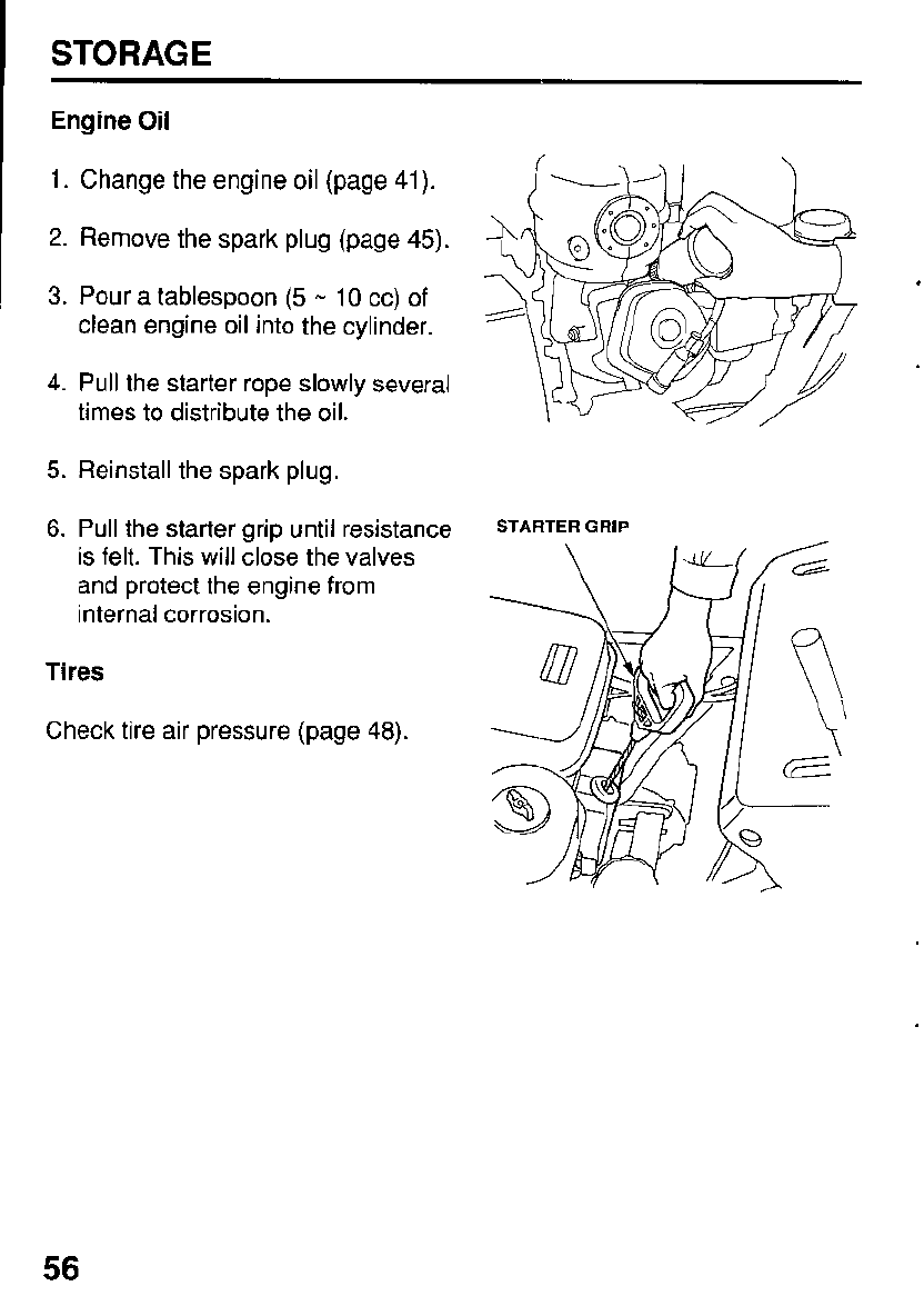
Engine Oil
1.
Change the engine oil (page
41).
2.
Remove the spark plug (page
45).
3.
Pour a tablespoon
(5
-
10
cc) of
clean engine oil into the cylinder.
4.
Pull the starter rope slowly several
times to distribute the oil.
5.
Reinstall the spark plug.
6.
Pull the starter grip until resistance
is felt. This will close the valves
and protect the engine from
internal corrosion.
Tires
Check tire air pressure (page
48).
STARTER
GRIP
56
STORAGE
STORAGE PRECAUTIONS
If
your snowblower will be stored with gasoline in the fuel tank and carburetor,
it is important to reduce the hazard of gasoline vapor ignition. Select a well-
ventilated storage area away from any appliance that operates with a flame,
~
such as a furnace, water heater, or clothes dryer.
Also
avoid any area with a
spark-producing electric motor, or where power tools are operated.
.
If
possible, avoid storage areas with high humidity, because that promotes rust
and corrosion.
Unless
all
fuel has been drained from the fuel tank, leave the fuel valve in the
OFF
position to reduce the possibility of fuel leakage.
Place the snowblower on a level surface. Tilting can cause fuel or oil leakage.
With the engine and exhaust system cool, cover the snowblower to keep out
dust.
A
hot engine and exhaust system can ignite or melt some materials.
Do
not use sheet plastic as a dust cover.
A
nonporous cover will trap moisture
around the engine, promoting rust and corrosion.
REMOVE FROM STORAGE
Check your snowblower as described in the
BEFORE
OfERATlONchapter
(page
18)
of this manual.
If
the fuel was drained during storage preparation,
fill
the tank with fresh
gasoline.
If
you keep a container of gasoline for refueling, be sure that it
contains only fresh gasoline. Gasoline oxidizes and deteriorates over time,
causing hard starting.
I
If
the cylinder was coated with oil during storage preparation, the engine may
smoke briefly at startup. This is normal.
57
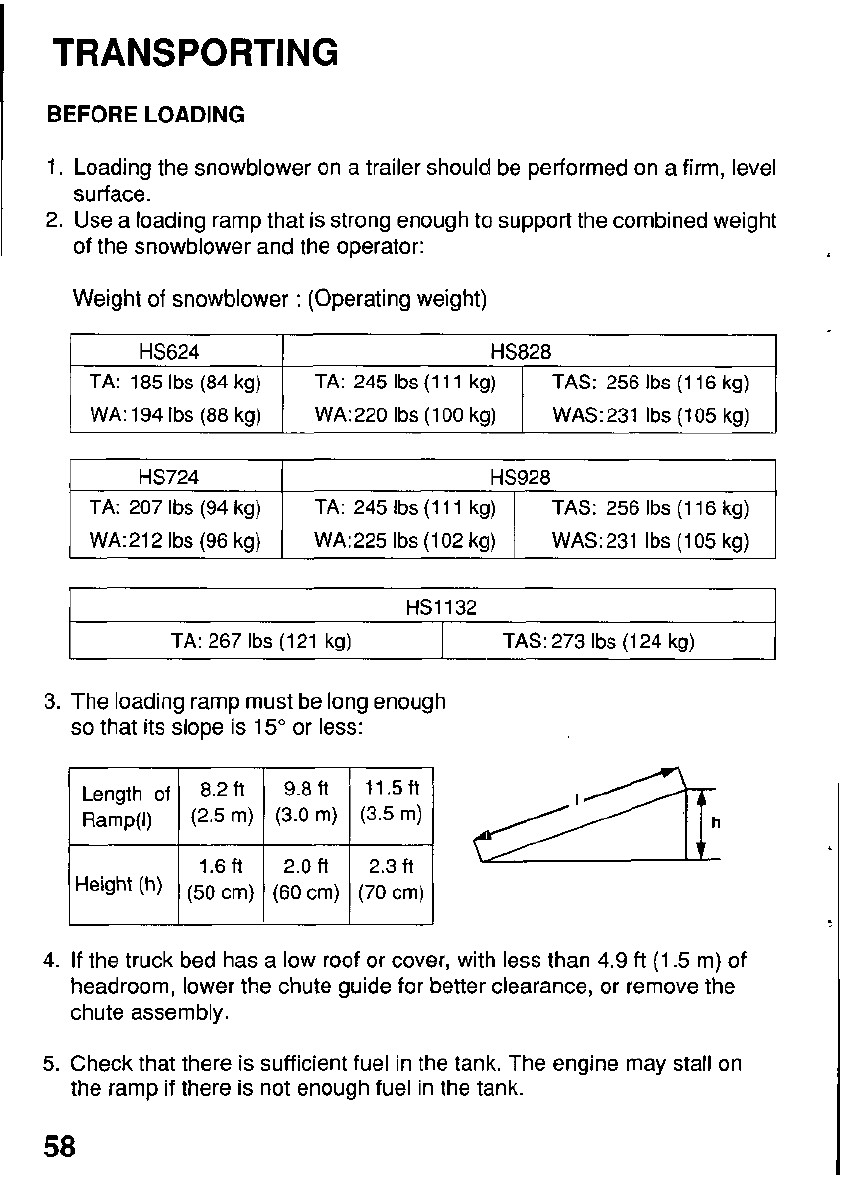
TRANSPORTING
BEFORE
LOADING
1.
Loading the snowblower
on
a trailer should be performed on a firm, level
2.
Use a loading ramp that is strong enough to support the combined weight
surface.
of the snowblower and the operator:
Weight of snowblower
:
(Operating weight)
HS624 HS828
TA: 185
Ibs
(84 kg)
WA: 194
Ibs
(88 kg)
TAS: 256
Ibs
(1 16 kg)
TA: 245
Ibs
(1 11 kg)
WAS:231
Ibs
(105 kg)
WA:220
Ibs
(1
00
kg)
HS724 HS928
TA: 207
Ibs
(94 kg)
WA:225
Ibs
(102 kg) WA:212
Ibs
(96 kg)
TAS: 256
Ibs
(1 16 kg)
TA: 245
Ibs
(1 11 kg)
WAS:231
Ibs
(105 kg)
I
HS1132
I
TA:
267
Ibs
(1 21 kg)
I
TAS: 273
Ibs
(1
24 kg)
~~
-1
3.
The loading ramp must be long enough
so
that its slope is
15"
or
less:
I
1.6ft
1
2.0ft
I
2.3ft
Height
(h)
(50
cm) (60 cm)
(70
cm)
4.
If
the truck bed has a low roof
or
cover, with less than
4.9
ft
(1.5
m) of
headroom, lower the chute guide for better clearance, or remove the
chute assembly.
5.
Check that there is sufficient fuel in the tank. The engine may stall on
the ramp
if
there is not enough fuel in the tank.
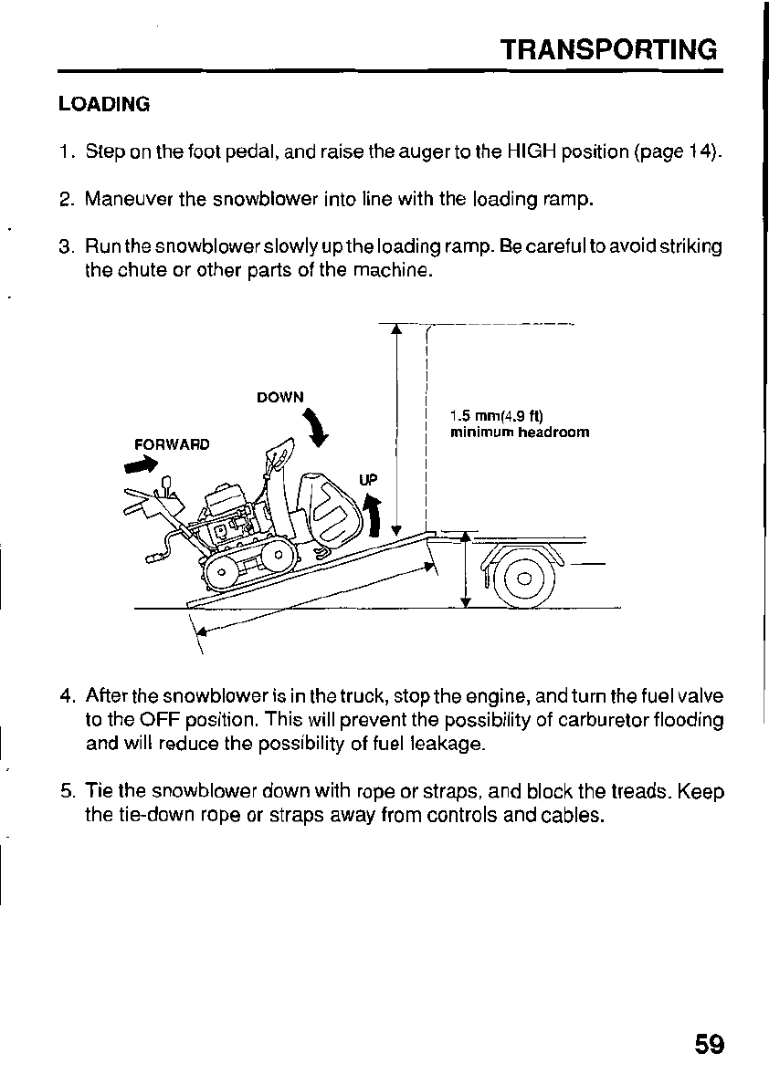
TRANSPORTING
LOADING
1.
Step on the foot pedal, and raise the auger to the
HIGH
position (page
14).
2.
Maneuver the snowblower into line with the loading ramp.
3.
Run the snowblower slowly up the loading ramp. Be careful to avoid striking
the chute or other parts of the machine.
DOWN
I/
I
FORWARD
4.
After the snowblower is in the truck, stop the engine, and turn the fuel valve
to the
OFF
position. This will prevent the possibility of carburetor flooding
and will reduce the possibility of fuel leakage.
5.
Tie the snowblower down with rope or straps, and block the treads. Keep
the tie-down rope or straps away from controls and cables.
59
TAKING CARE
OF
UNEXPECTED PROBLEMS
ENGINE PROBLEMS
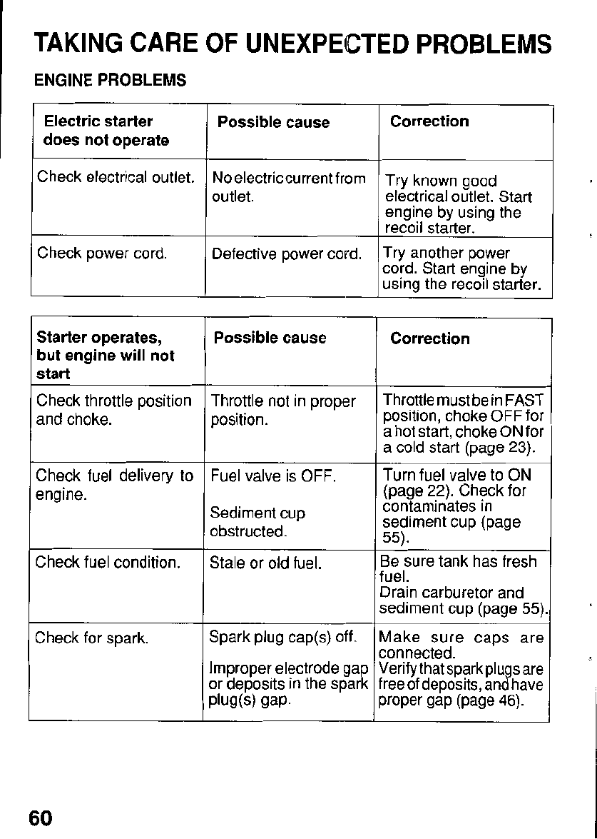
Electric starter
does not operate
Check electrical outlet.
Possible cause
No
electriccurrent from
outlet.
Check power cord. Defective power cord.
I
Starter operates,
but engine will not
start
Check throttle position
and choke.
Check fuel delivery
to
engine.
Check fuel condition.
Check for spark.
Possible cause
Throttle not in proper
position.
Fuel valve is OFF.
Sediment cup
obstructed.
Stale or old fuel.
Spark plug cap@)
off.
Improper electrode gap
or deposits in the spark
PlWm
gap-
7
Correction
Try known good
electrical outlet. Start
engine by using the
recoil starter.
Try another power
cord. Start engine by
using the recoil starter.
Correction
Throttle must be in FAST
position, choke OFF for
a hot start, choke
ON
for
a cold start (page
23).
Turn fuel valve
to
ON
(page
22).
Check for
contaminates in
sediment cup (page
55).
3e sure tank has fresh
uel.
)rain carburetor and
;ediment cup (page
55)
Aake sure caps are
:onnected.
Ierify that sparkplugs are
reeof deposits, and have
roper gap (page
46).
TAKING CARE
OF
UNEXPECTED PROBLEMS
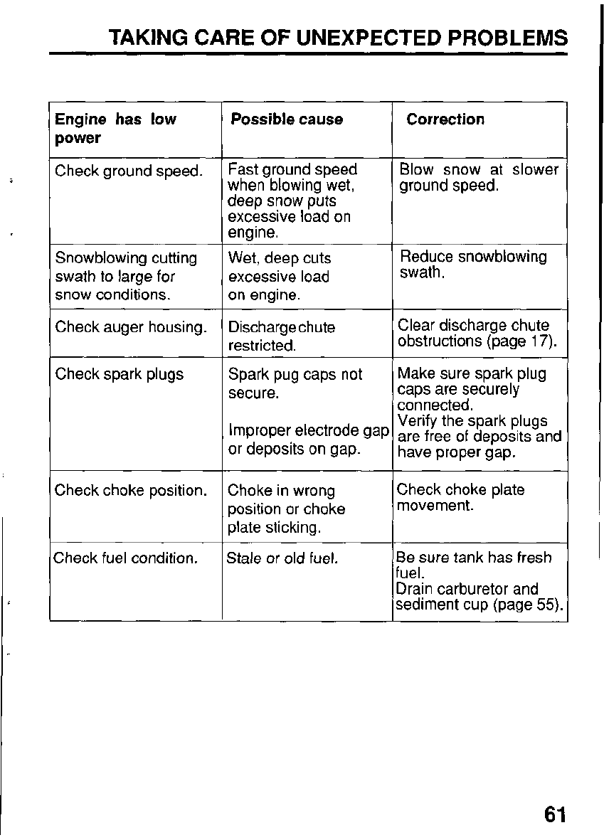
Engine has low
power
Check ground speed.
Snowblowing cutting
swath to large for
snow conditions.
Check auger housing.
~ ~~
Check spark plugs
Check choke position.
Check fuel condition.
Possible cause
Fast ground speed
when blowing wet,
deep snow puts
excessive load on
engine.
Wet, deep cuts
excessive load
on engine.
Dischargechute
restricted.
Spark pug caps not
secure.
Improper electrode gay
or deposits on gap.
Choke in wrong
position
or
choke
plate sticking.
Stale or old fuel.
Correction
Blow snow at slower
ground speed.
Reduce snowblowing
swath.
Clear discharge chute
obstructions (page
17).
Make sure spark plug
caps are securely
connected.
Verify the spark plugs
are free
of
deposits and
have proper gap.
Check choke plate
movement.
~
3e sure tank has fresh
uel.
)rain carburetor and
jediment cup (page
55).
~~
61
TAKING CARE OF UNEXPECTED PROBLEMS
DRIVE PROBLEMS
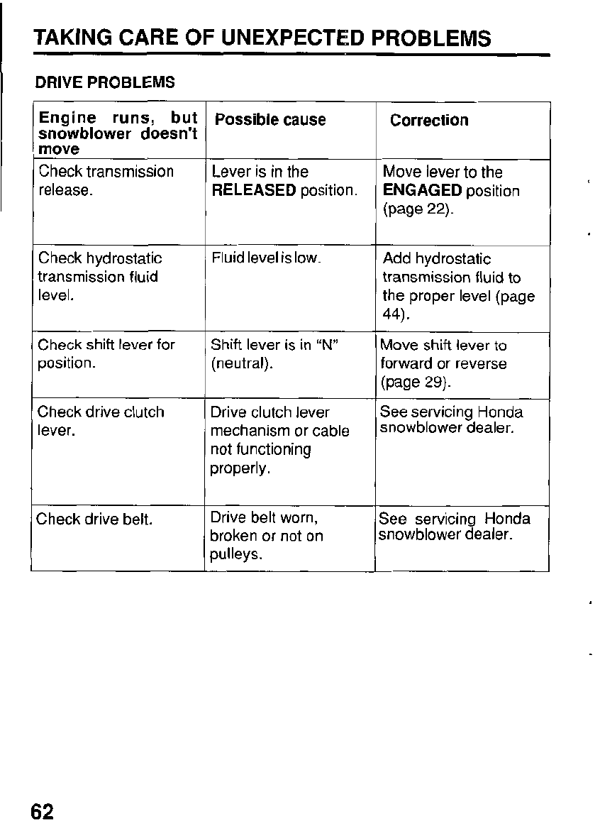
Engine runs, but
snowblower doesn’t
move
Check transmission
release.
Check hydrostatic
transmission fluid
level.
Check shift lever for
position.
Check drive clutch
lever.
:heck drive belt.
Possible cause
Lever is in the
RELEASED
position.
Fluid level is low.
Shift lever is in
“N”
(neutral).
Drive clutch lever
mechanism or cable
not functioning
properly.
Drive belt worn,
broken or not on
pulleys.
Correction
Move lever to the
ENGAGED
position
(page
22).
Add hydrostatic
transmission fluid to
the proper level (page
44).
Move shift lever
to
forward or reverse
(page
29)-
See servicing Honda
snowblower dealer.
See servicing Honda
snowblower dealer.
62
TAKING CARE
OF
UNEXPECTED PROBLEMS
SNOWBLOWER PROBLEMS
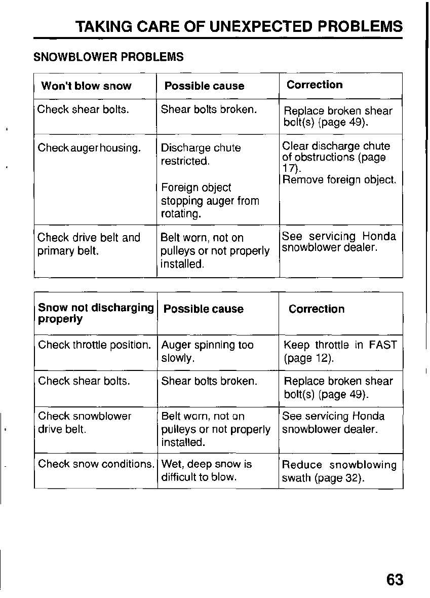
Won't blow snow
Check shear bolts.
Checkauger housing.
Check drive belt and
primary belt.
Snow not discharging
properly
Check throttle position.
Check shear bolts.
Check snowblower
drive belt.
~ ~ ~
Check snow conditions.
Possible cause
Shear bolts broken.
Discharge chute
restricted.
Foreign object
stopping auger from
rotating.
Belt worn, not on
pulleys or not properly
installed.
Possible cause
Auger spinning too
slowly.
Shear bolts broken.
Belt worn, not on
pulleys or not properly
installed.
Wet, deep snow is
difficult
to
blow.
Correction
___
~ ~~
Replace broken shear
bolt@) (page 49).
Clear discharge chute
of obstructions (page
17).
Remove foreign object.
See servicing Honda
snowblower dealer.
Correction
Keep throttle in
FAST
(page
1
2).
Replace broken shear
bolt@) (page 49).
See servicing Honda
snowblower dealer.
3educe snowblowing
swath (page
32).
63
TAKING CARE
OF
UNEXPECTED PROBLEMS
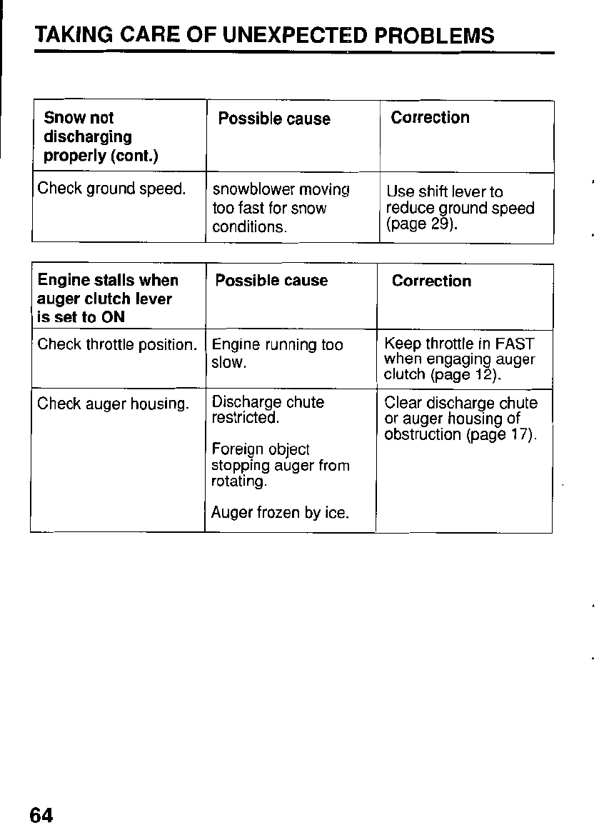
Snow not
discharging
properly (cont.)
Check ground speed.
Possible cause Correction
snowblower moving
too fast for snow
conditions.
Use shift lever to
reduce ground speed
(page
29).
Engine stalls when
auger clutch lever
is set to
ON
Check throttle position.
Check auger housing.
Possible cause
Engine running too
slow.
Discharge chute
restricted.
Foreign object
stopping auger from
rotating.
Auger frozen by ice.
Correction
Keep throttle in
FAST
when engaging auger
clutch (page
12).
Clear discharge chute
or auger housing of
obstruction (page
17).
64
TECHNICAL
&
CONSUMER INFORMATION
Carburetor Modification for
High
Altitude Operation
At high altitude, the standard carburetor air-fuel mixture will be too rich.
Performance will decrease, and fuel consumption will increase.
A
very rich
mixture will also foul the spark plug and cause hard starting. Operation at an
altitude that differs from that at which this engine was certified, for extended
periods of time, may increase emissions.
High altitude performance can be improved by a specific modifications to the
carburetor.
If
you always operate your pump at altitudes above
5,000
feet
(1,500 meters) have your servicing dealer perform this carburetor modification.
This engine, when operated at high altitude with the carburetor modifications
for high altitude use, will meet each emission standard throughout its useful
life.
Even with carburetor modification, engine horsepower will decrease about
3.5%for each 1,000-foot (300-meter) increase in altitude. The effect of altitude
on horsepower will be greater than this
if
no carburetor modification is made.
LNOTlCE
I
When the carburetor has been modified for high altitude operation, the air-fuel
mixture will be too lean for low altitude use. Operation at altitudes below
5,000
feet
(1,500
meters) with a modified carburetor may cause the engine to
overheat and result in serious engine damage. For use at low altitudes, have
your servicing dealer return the carburetor to original factory specifications.
66
TECHNICAL
&
CONSUMER INFORMATION
Oxygenated
Fuels
Some conventional gasolines are being blended with alcohol or an ether
compound. These gasolines are collectively referred to as oxygenated fuels.
To meet clean air standards, some areas of the United States and Canada use
oxygenated fuels to help reduce emissions.
If
you use an oxygenated fuel, be sure it is unleaded and meets the minimum
octane rating requirement.
Before using an oxygenated fuel, try to confirm the fuel’s contents. Some
states/provinces require this information to be posted on the pump.
The following are the EPA-approved percentages of oxygenates:
ETHANOL
-
(ethyl or grain alcohol)
10%
by volume
You may use gasoline containing up to
10%
ethanol by
volume. Gasoline containing ethanol may be marketed
under the name “Gasohol”.
MTBE
(Methyl Tertiary Butyl Ether)
15%
by volume
You may use gasoline containing up to
15%
MTBE by
volume.
METHANOL
-
(methyl or wood alcohol)
5%
by volume
You may use gasoline containing up to
5%
methanol by
volume, as long as it also containscosolvents and corrosion
inhibitors
to
protect the fuel system.
Gasoline containing more than
5%
methanol by volume
may cause starting and/or performance problems. It may
also damage metal, rubber, and plastic parts of your fuel
system.
Fuel system damage or performance problems resulting from the use of an
oxygenated fuel containing more than the percentages of oxygenates men-
tioned above are not covered under warranty.
67
TECHNICAL
&
CONSUMER INFORMATION
Emission Control System Information
Source of Emissions
The combustion process produces carbon monoxide, oxides
of
nitrogen, and
hydrocarbons. Control
of
hydrocarbons and oxides
of
nitrogen is very impor-
tant because, under certain conditions, they react to form photochemical
smog when subjected to sunlight. Carbon monoxide does not react in the
same way, but it is toxic.
Honda uses lean carburetor settings and other systems to reduce the
emissions of carbon monoxide, oxides
of
nitrogen, and hydrocarbons.
The
U.S.
and California Clean Air Act
EPA and California regulations require all manufacturers to furnish written
instruction describing the operation and maintenance of emission control
systems.
The following instructions and procedures must be followed in order to keep
the Honda engine emissions within the emission standards.
Tampering and Altering
Tampering with or altering the emission control system may increase emis-
sions beyond the legal limit. Among those acts that constitute tampering are:
Removal or alteration of any part of intake, fuel, or exhaust system.
Altering or defeating the governor linkage or speed-adjusting mechanism
to cause the engine to operate outside its design parameters.
68
TECHNICAL
&
CONSUMER INFORMATION
Problems That May Affect
Emissions
If
you are aware of any of the following symptoms, have your engine inspected
and repaired by your authorized Honda servicing dealer.
Hard starting or stalling after starting.
Rough idle.
Misfiring or backfiring under load.
0
Afterburning (backfiring).
Black exhaust smoke or high fuel consumption.
Replacement Parts
The emission control systems on your new Honda engine were designed,
built, and certified to conform with
EPA
and California emission regulations.
We recommend the use genuine Honda parts whenever you have mainte-
nance done. These original-design replacement parts are manufactured to
the same standards as the original parts,
so
you can be confident
of
their
performance. The use of replacement parts. that are not of the original design
and quality may impair the effectiveness of your emission control system.
A
manufacturer of an aftermarket part assumes the responsibility that the part
will not adversely affect emission performance. The manufacturer or rebuilder
of the part must certify that use of the part will not result in afailure of the engine
-
to comply with emission regulations.
Maintenance
Follow the Maintenance Schedule on page
37.
Remember that this schedule
is based on the assumption that your machine will be used for its designed
purpose. Sustained high-load operation, will require more frequent service.
69
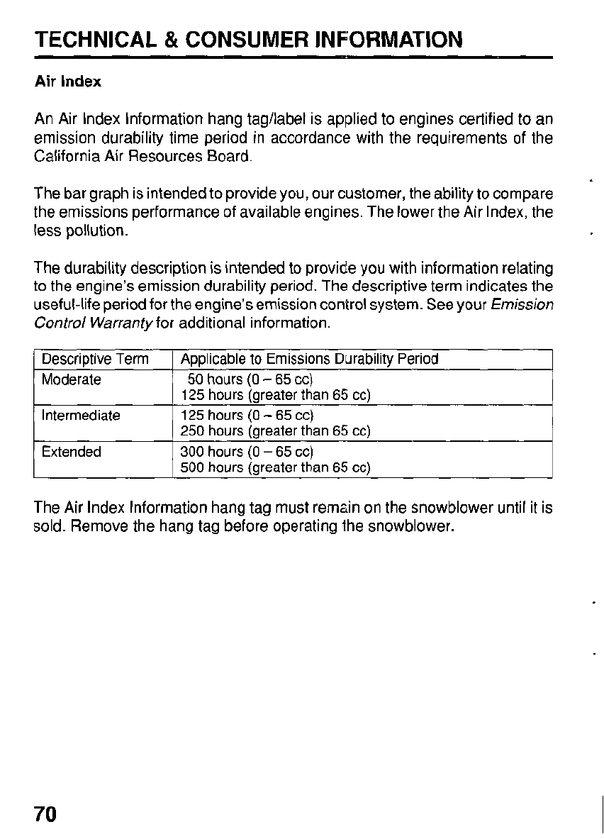
TECHNICAL &
CONSUMER
INFORMATION
Air
Index
An Air Index Information hang tag/label is applied to engines certified to an
emission durability time period in accordance with the requirements of the
California Air Resources Board.
The bar graph is intended to provide you, our customer, the ability to compare
the emissions performance of available engines. The lower the Air Index, the
less pollution.
The durability description is intended
to
provide you with information relating
to the engine’s emission durability period. The descriptive term indicates the
useful-life period for the engine’s emission control system. See your
Emission
Control Warranty
for additional information.
I
Descriptive Term
I
Applicable to Emissions Durability Period
Moderate
300
hours
(0
-
65
CC)
Extended
125
hours
(0
-
65
cc)
Intermediate
50
hours
(0
-
65
cc)
125
hours (greater
than
65
cc)
250
hours (greater than
65
cc)
500
hours (greater than
65
cc)
The Air Index Information hang tag must remain
on
the snowblower until it is
sold. Remove the hang tag before operating the snowblower.
70
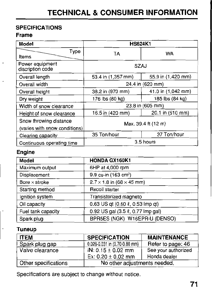
TECHNICAL
&
CONSUMER INFORMATION
SPECIFICATIONS
Frame
Model
HS624K1
TA WA
Power equipment SZAJ
discription code
Overall length 53.4 in (1,357
mm)
I
55.9 in (1,420 mm)
Overall width
Snow throwing distance
20.1 in (510
mm)
16.5 in (420
mm)
Height of snow clearance
23.8 in (605 mm)
Width of snow clearance
185
Ibs
(84 kg)
176
Ibs
(80 kg)
Dry weight
41
.O
in (1,042
mm)
38.2 in (970
mm)
Overall height
24.4 in (620
mm)
Max. 39.4 ft (12
rn)
(varies with snow conditions)
Clearing capacitv 37 Ton/hour
35 Ton/hour
I
Continuous operating time
I
3.5 hours
Engine
Model
9.9 cu-in (163 cm3)
Displacement
6HP at 4,000 rpm Maximum output
HONDA GX160K1
Bore
x
stroke 2.7
x
1.8 in (68
x
45
mm)
Starting method Recoil starter
Ignition system Transistorized magneto
Oil capacity
Fuel tank capacity
0.63 US qt
(0.60
k?,
0.53
Imp qt)
BPR5ES (NGK) W16EPR-U (DENSO)
Spark plug
0.92
US
gal (3.5
k?,
0.77 Imp gal)
Tuneur,
IM
I
SPECIFICATION
I
R
.
-
-.--
-.
,
RAINTENANCE
t
Ex:
0.20
f
0.02
mm
I
Honda dealer
Other specifications
No
other adjustments
needed.
Specifications are subject to change without notice.
71
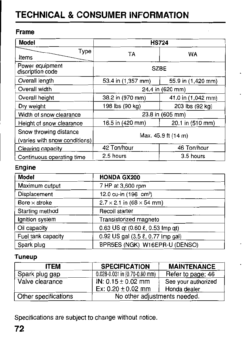
TECHNICAL
&
CONSUMER INFORMATION
Frame
Model
HS724
Items
-1
TA
I
WA
.
I
Power equipment
discription code
SZBE
Overall length 53.4 in (1,357
mm)
1
55.9 in (1,420
mm)
Overall width 24.4 in (620
mm)
Overall height
Dry weight
41
.O
in (1,042
mm)
38.2 in (970
mm)
20.1 in (510
mm)
16.5 in (420
mm)
Height
of
snow clearance
23.8 in (605
mm)
Width
of
snow clearance
203
Ibs
(92 kg) 198
Ibs
(90 kg)
Snow throwing distance
(varies with snow conditions)
Clearinq capacity
Continuous operating time
46 Ton/hour 42 Ton/hour
3.5 hours
2.5 hours
Max. 45.9
ft
(14
m)
Engine
Model
BPR5ES (NGK)
W16EPR-U
(DENSO) Spark plug
0.92
US
gal (3.5
e,
0.77 Imp gal)
Fuel tank capacity
0.63
US
qt (0.60
e,
0.53 Imp qt)
Oil capacity
Transistorized magneto
Ignition system
Recoil starter Starting method
2.7
x
2.1 in (68
x
54
mm)
Bore
x
stroke
12.0 cu-in (196 cm3)
Displacement
7
HP
at 3,600 rpm
Maximum output
HONDA
GX200
Tuneup
ITEM
No
other adiustments needed.
Other specifications
Honda dealer
Ex:
0.20
f
0.02
mm
See your authorized
IN:
0.1
5
*
0.02
mm Valve clearance Refer to page:
46
0.028-0.031
in
(0.70-0.80
mrn)
Spark plug gap
MAINTENANCE SPECIFICATION
Specifications are subject to change without notice.
72
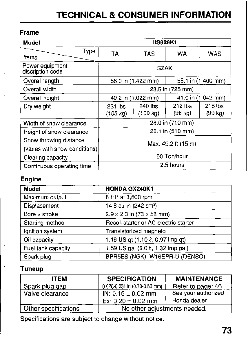
TECHNICAL
&
CONSUMER INFORMATION
Frame
Model HS828K1
TAS WAS
WA
Power equipment
discription code
I
SZAK
Overall length
40.2 in (1,022 mrn)
I
41
.O
in (1,042 mrn)
Overall height
28.5 in (725 mrn)
Overall width
56.0 in (1,422 rnm)
I
55.1 in (1,400 mrn)
Dry weight
I
Width
of
snow clearance
I
28.0 in (710 mrn)
Height
of
snow clearance
Snow throwing distance
20.1 in
(510
rnm)
Max. 49.2 ft
(15
m)
(varies with snow conditions)
Clearing capacity
50
Ton/hour
Continuous operating time 2.5 hours
Engine
I
Model
I
HONDA GX240K1
1
Maximum output
1
8
HP
at 3,600 rpm
I
Displacement 2.9
x
2.3
in (73
x
58 rnrn)
Bore
x
stroke
14.8 cu-in (242 cm3)
Starting method
Transistorized rnaaneto
lanition svstem
Recoil starter or AC electric starter
Oil capacity
BPR5ES
(NGK)
W16EPR-U (DENSO)
Spark plug
1.59
US
gal (6.0
4,
1.32 Imp gal)
Fuel tank capacity
1.16
US
qt (1.10
4,
0.97 Imp qt)
Tuneup
ITEM
See your authorized
IN:
0.1
5
k
0.02
mm
Valve clearance Refer to paae:
46
0.028-0.031
in
(0.70-0.80
mm)
Spark plua aap
MAINTENANCE SPECIFICATION
Ex:
0.20
k
0.02
mm
1
Honda dealer
Other specifications
No
other adjustments needed.
Specifications are subject to change without notice.
73
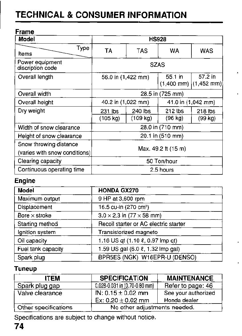
TECHNICAL & CONSUMER INFORMATION
Frame
Model
HS928
TAS WAS
WA
Power equipment
discription code
Overall length 57.2 in
55.1 in
56.0 in (1,422
mm)
SZAS
(1,400 mm) (1,452
mm)
Overall width
21 8
Ibs
21
2
Ibs
240
Ibs
231
Ibs
Dry weight
41
.O
in (1,042 mm)
40.2 in (1,022
mm)
Overall height
28.5 in (725
mm)
(105 kg) (109 kg) (96 kg) (99 kg)
Width
of
snow clearance 28.0 in (710
mm)
I
Height
of
snow clearance
I
20.1 in (510
mrn)
Snow throwing distance
(varies with snow conditions) Max. 49.2 ft
(1
5
m)
Clearing capacity
2.5 hours
Continuous operating time
50
Ton/hour
Engine
Model
9
HP at 3,600 rpm Maximum output
HONDA
GX270
Displacement 3.0
x
2.3 in (77
x
58
mm)
Bore
x
stroke
16.5 cu-in (270 cm3)
Starting method
BPR5ES
(NGK)
W16EPR-U (DENSO)
Spark plug
1.59 US gal (6.0
f,
1.32
Imp
gal)
Fuel tank capacity
1.16USqt(l.lOi?,0.97Impqt)
Oil capacity
Transistorized magneto
Ignition system
Recoil starter or AC electric starter
Tuneup
ITEM
No
other adiustments needed.
Other
mecifications
See your authorized
IN: 0.15
k
0.02
mm
Valve
clearance
Refer
to
page:
46
0.028-0.031
in
(0.70-0.80
mm)
Spark
plug
gap
MAINTENANCE
SPECIFICATION
Ex:
0.20
f
0.02
mm
Honda dealer
Specifications are subject to change without notice.
74
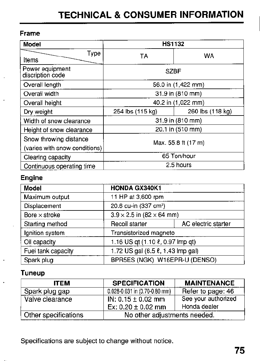
TECHNICAL
&
CONSUMER INFORMATION
Frame
Model
HS1132
TA WA
Power equipment
discription code
Overall length 56.0 in (1,422
mm)
Overall width
40.2 in (1,022
mm)
Overall heiaht
31.9 in (81
0
mm)
SZBF
Dry weight
2.5 hours
Continuous operating time
65 Ton/hour
Clearing capacity
(varies with snow conditions)
Snow throwing distance
20.1 in (510
mm)
Height
of
snow clearance
31.9 in (81
0
mm)
Width
of
snow clearance
260
Ibs
(1 18 kg)
254
Ibs
(1 15 kg)
Max. 55.8
ft
(1 7
m)
Engine
Model
Maximum outwt
HONDA GX340K1
11 HP at 3,600
rwn
I
Displacement
I
20.6 cu-in (337 cm3)
I
Bore
x
stroke
Starting method
3.9
x
2.5 in (82
x
64
mm)
Recoil starter
I
AC
electric starter
Ignition system
1.72
US
gal (6.5
t,
1.43 Imp gal)
Fuel tank capacity
1.16 US qt (1.10
t,
0.97 Imp qt) Oil capacity
Transistorized magneto
I
Spark plug
I
BPR5ES
(NGK)
W16EPR-U (DENSO)
Tuneup
ITEM
I
SPECIFICATION
I
MAINTENANCE
I
Spark plug gap
See your authorized
IN:
0.15
f
0.02
mm Valve clearance Refer to page:
46
0.028-0.031
in
(0.70-0.80
mrn)
I
I
Ex:
0.20
f
0.02
mm
1
Honda dealer
I
I
Other specifications
No
other adjustments needed.
Specifications are subject to change without notice.
75
TECHNICAL
&
CONSUMER INFORMATION
CONSUMER INFORMATION
Honda
Publications
These publications will give you additional information for maintaining and
repairing your snowblower.
You
may order them from your Hondasnowblower
I
dealer.
Shop
Manual
This manual covers complete maintenance and overhaul procedures. It is
intended to be used by a skilled technician.
Parts Catalog
This manual provides complete, illustrated parts lists.
76
TECHNICAL
&
CONSUMER INFORMATION
Warranty Service Information
Honda Power Equipment dealership personnel are trained professionals.
They should be able to answer any question you may have.
If
you encounter
a problem that your dealer does not solve to your satisfaction, please discuss
.
it with the dealership’s management. The Service Manager or General
Manager can help. Almost all problems are solved in this way.
.
If
you are dissatisfied with the decision made by dealership’s management,
contact the Honda Power Equipment Customer Relations Office. You can
write:
American Honda Motor
Co.,
Inc.
Power Equipment Division
Customer Relations Office
4900 Marconi Drive
Alpharetta, Gergia
30005
-
8847
Or telephone: (770) 497
-
6400
When you write or call, please give us this information:
0
Model and serial numbers (see page 65)
0
Name
of
the dealer who sold the lawn tractor to you
0
Name and address of the dealer who services your lawn tractor
Date of purchase
0
Your name, address, and telephone number
0
A detailed description of the problem
77
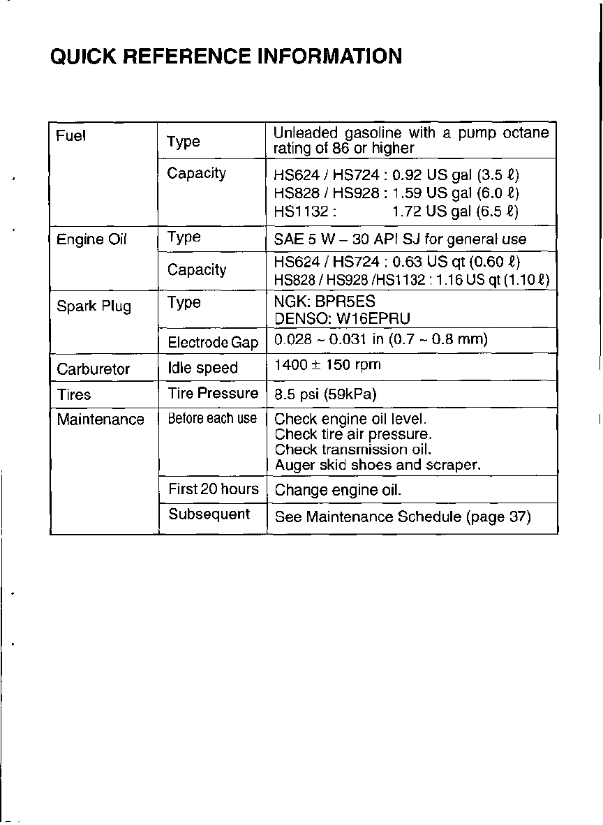
QUICK REFERENCE INFORMATION
Fuel
Engine
Oil
Spark Plug
Carburetor
Tires
Maintenance
Capacity
Capacity
Electrode Gap
Idle speed
Tire Pressure
Before
each
use
First 20 hours
Subsequent
Unleaded gasoline with a pump octane
rating
of
86 or higher
HS624
/
HS724
:
0.92
US
gal (3.5
f)
HS828
/
HS928
:
1.59 US gal
(6.0
f)
HS1132
:
1.72 US gal (6.5
1)
SAE
5
W
-
30
API
SJ
for general use
HS624
/
HS724
:
0.63 US qt (0.60
f)
HS828/HS928/HS1132: 1.16USqt(1.10!)
NGK:
BPR5ES
DENSO:
W16EPRU
0.028
-
0.031 in (0.7
-
0.8 mm)
1400
f
150 rpm
8.5 psi (59kPa)
Check engine
oil
level.
Check tire air pressure.
Check transmission oil.
Auger skid shoes and scraper.
Change engine oil.
See Maintenance Schedule (page 37)